JP4146532B2 - Air conditioner - Google Patents
Air conditionerDownload PDFInfo
- Publication number
- JP4146532B2 JP4146532B2JP21037297AJP21037297AJP4146532B2JP 4146532 B2JP4146532 B2JP 4146532B2JP 21037297 AJP21037297 AJP 21037297AJP 21037297 AJP21037297 AJP 21037297AJP 4146532 B2JP4146532 B2JP 4146532B2
- Authority
- JP
- Japan
- Prior art keywords
- air
- air conditioner
- indoor
- blowing
- remote controller
- Prior art date
- Legal status (The legal status is an assumption and is not a legal conclusion. Google has not performed a legal analysis and makes no representation as to the accuracy of the status listed.)
- Expired - Fee Related
Links
Images


Landscapes
- Air Filters, Heat-Exchange Apparatuses, And Housings Of Air-Conditioning Units (AREA)
- Air Conditioning Control Device (AREA)
Description
Translated fromJapanese【0001】
【発明の属する技術分野】
本発明は空気調和機にかかり、特に空気清浄機能を有する空気調和機に関する。
【0002】
【従来の技術】
図8に従来室内機8の基本構成を示す。1は上部吸込口、2は前面吸込口、3aは上下風向板、3bは左右風向板、4はプレフィルター、5は空気清浄フィルター、6は室内送風機、7は気流の流れを示す流線、9は熱交換器、10は吐出口、11は上部吸込み口グリル、12は前面吸込み口グリル、13は通風路壁を示す。室内機の通風路は、流線7に添って、空気吸い込み口1及び2、空気清浄フィルター5、プレフィルター4、熱交換器9、室内送風機6、空気吐出口10の順に構成されている。このため、冷房・暖房・除湿運転時には自動的に塵埃等の除去が行われる。なお、空気調和機の室外機は省略する。
【0003】
図9はプレフィルター4と空気清浄フィルター5の詳細を示す図で、プレフィルター4は上部吸込み口1から前面吸込み口2に渡る通風路全面を覆い、粗大ほこり類の除去を行う。このため比較的粗いメッシュ構造のフィルターである。空気清浄フィルター5は微細ほこり類の除去を目的とし、素材に静電加工を施したフィルターである。固定枠14で通風路の一部に取り付けられている。かかる2種類のフィルターを通風路に配置し、空気調和機の冷房・除湿・暖房運転時に空気清浄を行う構成である。残念ながら、かかるフィルターには満足できる抗菌や脱臭機能はない。また、空気清浄のみの独立した運転機能はなく、空気清浄機能を希望する場合には、選択操作が面倒であるが送風運転で代用するしか方法はない。
【0004】
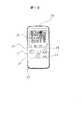
図10は従来リモートコントローラ27の開閉蓋を閉めた状態を示す。20は空調機本体の運転開始と終了を指令する運転/停止釦、21は運転終了時間を設定するおやすみタイマー釦、22は室温設定値を変更する室温設定釦、23は運転能力を増大させるパワフル釦、24は除湿運転を設定する除湿釦、25は運転指令を無線で送信する送信部、26は液晶表示画面である。使用者が該当する運転内容の操作釦を押せば、運転指令が送信部25送信され希望の運転となる。以上説明した、よく使われる機能の操作釦は開閉蓋の外に配置してあり、簡単に操作できる構造となっている。空気清浄のみの機能は搭載されていないため、当然ながら、それに該当する釦はない。
【0005】
開閉蓋を開けた状態は省略する。
【0006】
図11は制御回路部40の運転指令部の模式を示す。41はリモートコントローラ信号を受信する受信部、42は信号内容の判断及び指令部、43は室内機8及び室外機を制御するための運転情報を記録してある記憶部、44は各要素に直接運転指令を出す運転指令部である。
【0007】
以上説明した如く、従来空気調和機は室内機通風路7にプレフィルター4と空気清浄フィルター5を設置し、冷房・暖房・除湿運転時に塵埃等の除去を行う構成である。空気清浄フィルタ−を設置した例としては、例えば特公平7−30926号が挙げられる。
【0008】
【発明が解決しようとする課題】
上記従来技術は、下記のような問題があることを見出した。。
【0009】
(1)住宅構造がアルミサッシュ等の普及により高気密化し、自然換気量が減少したため、生活に伴う湿気や室内空気の汚れが排出されにくくなった。このため、黴の繁殖、臭いこもり、室内壁の汚れ等による被害が顕著になってきた。更に近年、清潔志向から、室内の浮遊細菌類の除去ニーズも高まっている。
【0010】
かかる背景から、空気清浄機能の内容が従来の塵埃類の除去機能に加え、細菌・黴・生活臭などの除去機能が求められる。
【0011】
(2)上述の如く、空気清浄機能に対するニーズは高く、空気清浄運転のみの独立した運転モードが求められている。更に、空気調和機の普及に伴い、運転操作者はお年寄りから子供まで幅広くなっている。このため、かかる機器についての知識の有無に係わらず、誰もが容易に操作できる簡単な操作系とする必要がある。
【0012】
(3)空気調和機の内部が細菌・黴・生活臭などで汚れていたのでは、機器運転時に送風と共にかかる汚れ成分が室内空間に放出されることになり、好ましくない。かかる被害を防ぐには、空気調和機本体内部は常に清潔にしておく必要があり、そのための工夫が求められる。
【0013】
本発明は、上記課題を解消し、塵埃類の除去機能に加え、細菌・黴・生活臭などの除去機能を得ることを目的とする。
【0014】
【課題を解決するための手段】
塵埃等の粒子は従来どおり、プレフィルター4と空気清浄フィルター5で除去する構成とし、新しいニーズである防黴、抗菌、脱臭機能については、下記手段で対応する。
先ず、防黴機能については、黴は胞子状態で室内を浮遊しており、温度、湿度、エサの3条件が揃えば室内壁面、押入の中など、どこにでも繁殖する。しかも人間の活動領域ではこの条件は容易に満足される。唯一湿度については、制御可能であると共に、図12に示す如く、相対湿度65%以下では、好乾性の黴でも生育が押さえられることが分かっており、相対湿度をかかる湿度以下まで下げて対応することとした。
【0015】
更に、他の方法として、防黴剤を使う方法がある。防黴剤には、一般に農薬等の有機系が用いられているが、無機系についても、効果のあるものがいくつか実用化されている。セラミックス微粒子を用いた防黴剤もあり、かかる防黴剤の効果を図13に示す。本データは該セラミックス微粒子を練り込んだプラスチック板表面に、住宅内で最もよく見られるクロ黴の胞子培養液を滴下し、抑制効果を調べたものである。セラミックス微粒子を練り込んだプラスチック板は、その練り込み量と種類により効果に差はあるが、練り込んでいないブランクに比べ、時間経過と共に黴の菌数は大きく減少しており、防黴効果があるのがわかる。かかる防黴機能を通風路の一部に持たせることとした。
【0016】
次に、抗菌機能については、今日では、有機系や無機系さらには光触媒作用を利用したものなど様々な種類の抗菌剤があり、自由に選ぶことが出来る。一例として、上述の防黴効果を有するセラミックス微粒子の抗菌特性を図13と図14に示す。図14は黄色ブドウ球菌を、図15は大腸菌を用いた場合の抗菌特性を示す。試験方法は同じく、セラミックス微粒子を練り込んだプラスチック板に上記2種類の細菌培養液をそれぞれ滴下し、細菌の生存数を調べたものである。
【0017】
セラミックス微粒子を練り込んだプラスチック板はその練り込み量と種類により効果に差はあるが、練り込んでいないブランクに比べ、細菌数は時間経過と共に大きく減少し、抗菌効果を有することがわかる。従って、該セラミックス微粒子を練り込めば、抗菌効果が期待できることがわかる。そこで、かかる抗菌機能を通風路の一部に持たせることとした。
【0018】
最後に、脱臭機能については、住宅内にはタバコ、建材、食品など様々な臭い源があり、臭い源を断つと同時に、発生した臭い分子を吸着若しくは分解する機能が求められている。一般に、吸着剤としては活性炭が用いられるが、光脱臭作用を利用したものなど、多数ある。上記防黴と抗菌に使用したセラミックス微粒子にも臭い分子の分解機能がある。
【0019】
脱臭効果の一例を図16と図17に示す。図16はアンモニアを、図17はホルムアルデヒドを用いた場合の脱臭特性を示す。試験方法は、1m立方の箱の中に通風路にセラミックス微粒子練り込んだプラスチック板を取り付けた空気調和機を入れ、上記2種類の臭い分子をそれぞれ規定濃度まで満たした状態で、送風させ、臭い分子の減衰を調べたものである。セラミックス微粒子を練り込んだプラスチック板はその練り込み量と種類により効果に差はあるが、練り込んでいないブランクに比べ、臭い分子の残存率が時間経過と共に大きく減少し、脱臭効果のあるのがわかる。かかる脱臭機能を通風路の一部に持たせることとした。
【0020】
以上述べたごとく、防黴、抗菌、脱臭機能を通風路の一部に持たせることにより、課題を解決した。本発明ではセラミックス微粒子を中心に説明したが、かかる機能を有する方法なら、他の手段を用いてもよい。操作性等の他の課題の解決手段については、次の発明の実施形態の項で説明する。
【0021】
【発明の実施の形態】
図1に本発明の一実施例を示す室内機の側面断面構造を示したものある。図8と同一符号は同一部材である。本実施例は、通風路を構成する部材の吸込み口グリル11若しくは12、通風路壁13、送風機6、吐出口風向板3C若しくは3Bのいずれかに防黴、抗菌、脱臭機能を持たせた。この結果、浮遊細菌を捕集、分解し、クリーンな環境を保つことができた。図1では吐出口の上下風向板3Cに上述のセラミック微粒子を練り込んだ構成を示す。他の手段で防黴、抗菌、脱臭機能を持たせてもよい。
【0022】
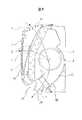
図2は本発明の他の実施例を示す。吸い込み口を前面2と上部1の2ヶ所とし、空気清浄フィルター5の位置を上部吸込み口1側へ移し、前面吸込み口開口部2に、セラミック微粒子を練り込んだ多孔通風板15を設けた構成である。なお、該多孔通風板の上流側には上下方向に移動可能な遮蔽板16を追加して設けてある。かかる構成とすることにより、通風路7に設けた該多孔通風板の防黴、抗菌、脱臭機能で浮遊細菌等を捕集・分解し、クリーンな環境を保つものである。
【0023】
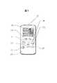
図3は本発明の他の実施例で、リモートコントローラ27に空気清浄運転の専用釦19を設け、該釦を押すことにより、ワンタッチで空気清浄運転が得られる構成とした。図4にこの釦を押したときの空気清浄運転の運転内容を示す。風向は風が直接人体に当たらないよう、上向きとし、風速は気流感を低減させるため最も低い微風とし、前面吸込み口の遮蔽板16を閉じて、上部吸込み口1に設けた空気清浄フィルター5に効果的に風を流し、清浄効果の向上を図った。
【0024】
かかる運転内容が選択される結果、防黴、抗菌、脱臭機能に加え、空気清浄性能の改善が図れる。更に運転騒音の低減や運転時の消費電力量の低減も図ることができる。また、リモートコントローラからワンタッチでかかる運転が選択でき、高齢者から子供まで容易に利用できるものである。
【0025】
図5は冷房や除湿運転時に除湿水で濡れた熱交換器を乾かすための送風運転パターンを示す。熱交換器が除湿水で濡れている場合には、そのまま放置すると空気調和機内部が湿度の高い状態で長時間保たれることになり、黴や細菌の繁殖が促進される。更にこれらの死骸等による臭い発生源ともなる。そこで、冷房や除湿運転終了後に、強制的に一定時間、送風運転を行い、本体を乾燥させ、空気調和機内部細菌や黴の繁殖を押さえる構造とした。即ち、本体の除湿若しくは冷房運転終了後、リモートコントローラからの指示に従い、一定時間送風運転を行う。既述の如く、相対湿度が65%以下では黴や細菌類の活動は押さえられるので、少なくとも、かかる湿度までは低下させる制御とした。
【0026】
なお、室温が上昇し、環境は悪くなるが、図6に示す如く、早く乾かすために、ヒートポンプの特性を利用し、暖房運転で乾燥させてもよい。
【0027】
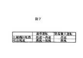
図7に本発明の他の実施例を示す。空気調和機を運転中には、空気中の汚れ分子が熱交換器を通過し、その時一部は熱交換器表面に付着する。冷房や除湿運転時には熱交換器表面は除湿水で濡れているため、かかる付着した汚れはこの除湿水で洗い流され、ドレン水と一緒に室外へ排出される。この洗浄力は当然ながら圧縮機の回転数を高くし、熱交換器の温度を下げて除湿水量を増やせば大きくなる。従って、図7に示す如く、通常運転時に比べ除湿水量を増大させる運転モードを作り、定期若しくは不定期に該モードを呼び出すことにより、除湿水量に変化を持たせ、付着汚れをきれいに落とす構成とした。
【0028】
【発明の効果】
以上説明した如く、本発明を採用することにより、次のような効果が生じ、清浄環境を提供できる。
先ず、通風路に練り込んだセラミックス微粒子の働きで、塵埃類の除去に加え、空中浮遊している細菌や真菌類に対し、防黴、抗菌、脱臭機能が追加された。このため、室内空気の清浄力の向上が図れる。また、専用釦で容易に空気清浄機能を利用できる。
【0029】
次いで、本体の乾燥モードにより、除湿水による熱交換器の洗浄により本体の清浄が図れる。この結果、本体内での黴の繁殖が押さえられ、臭い防止にも有効である。
【図面の簡単な説明】
【図1】本発明空気調和機の室内機を示す側面断面図
【図2】本発明空気調和機の室内機の構成を示す側面断面図
【図3】本発明の機能を搭載したリモートコントローラ外観図
【図4】本発明の送風運転条件を示す図
【図5】本発明の送風運転条件を示す図
【図6】本発明の送風運転条件を示す図
【図7】本発明の除湿運転条件を示す図
【図8】従来空気調和機の室内機の構成を示す側面断面図
【図9】従来空気調和機のフィルター構造を示す図
【図10】従来リモートコントローラの外観図
【図11】制御回路の模式図
【図12】黴の生育湿度を示す図
【図13】防黴特性を示す図
【図14】抗菌特性を示す図(黄色ブドウ球菌)
【図15】抗菌特を示す性図(大腸菌)
【図16】脱臭特性を示す図(アンモニア)
【図17】脱臭特性を示す図(ホルムアルデヒド)
【符号の説明】
1:上部吸込み口 2:前面吸込み口
3a:上下風向板 3b:左右風向板
3c:上下風向板 4:プレフィルター
5:空気清浄フィルター 6:室内送風機
7:流線 8:室内機
9:熱交換器 10:吐出口
15:多孔通風板 16:遮蔽板
19:空気清浄釦 20:運転/停止釦
23:パワフル釦 24:除湿釦
39:開閉蓋[0001]
BACKGROUND OF THE INVENTION
The present invention relates to an air conditioner, and more particularly to an air conditioner having an air cleaning function.
[0002]
[Prior art]
FIG. 8 shows a basic configuration of the conventional
[0003]
FIG. 9 is a diagram showing details of the pre-filter 4 and the air purifying
[0004]
FIG. 10 shows a state in which the open / close lid of the conventional
[0005]
The state where the open / close lid is opened is omitted.
[0006]
FIG. 11 shows a model of the operation command unit of the
[0007]
As described above, the conventional air conditioner has a configuration in which the pre-filter 4 and the air purifying
[0008]
[Problems to be solved by the invention]
The above prior art has been found to have the following problems. .
[0009]
(1) The housing structure has become highly air-tight due to the spread of aluminum sash and the like, and natural ventilation has decreased, so it has become difficult to exhaust moisture and indoor air pollution associated with daily life. For this reason, damage caused by the propagation of cocoons, stinking, dirt on indoor walls, etc. has become prominent. Furthermore, in recent years, there is a growing need for the removal of airborne bacteria in the room from the viewpoint of cleanliness.
[0010]
Against this background, the air purifying function is required to have a function of removing bacteria, soot, living odors, etc. in addition to the conventional dust removing function.
[0011]
(2) As described above, there is a high need for the air cleaning function, and an independent operation mode only for the air cleaning operation is required. Furthermore, with the widespread use of air conditioners, the number of driving operators has increased from the elderly to children. For this reason, it is necessary to provide a simple operation system that anyone can easily operate regardless of whether or not there is knowledge of such devices.
[0012]
(3) If the inside of the air conditioner is contaminated with bacteria, sputum, living odors, etc., it is not preferable because the contaminated component is discharged into the indoor space along with the ventilation during the operation of the device. In order to prevent such damage, it is necessary to keep the inside of the air conditioner body always clean, and a device for that purpose is required.
[0013]
An object of the present invention is to solve the above problems and to obtain a function of removing bacteria, soot, living odors, etc. in addition to a function of removing dust.
[0014]
[Means for Solving the Problems]
As usual, particles such as dust are removed by the pre-filter 4 and the air purifying
First of all, as for the fungicide function, the salmon floats in the room in a spore state, and if it meets all three conditions of temperature, humidity and food, it propagates everywhere, such as in the wall of the room and in the indentation. Moreover, this condition is easily satisfied in human activity areas. The only humidity is controllable, and as shown in FIG. 12, it is known that growth is suppressed even in a dry cocoon at a relative humidity of 65% or less, and the relative humidity is lowered to such a humidity or less. It was decided.
[0015]
Further, as another method, there is a method using an antifungal agent. Generally, organic compounds such as agricultural chemicals are used as antifungal agents, but some effective inorganic compounds have been put to practical use. There is also an antifungal agent using ceramic fine particles, and the effect of such an antifungal agent is shown in FIG. This data is the result of investigating the inhibitory effect of dripping black spore culture broth, which is most commonly found in a house, on the surface of a plastic plate containing ceramic fine particles. The effect of the plastic plate with ceramic fine particles is different depending on the amount and type of kneading. I know that there is. It was decided to give such a fender function to a part of the air passage.
[0016]
Next, regarding antibacterial functions, there are various types of antibacterial agents such as organic, inorganic, and photocatalytic ones that can be freely selected. As an example, the antibacterial property of the ceramic fine particles having the above-mentioned antifungal effect is shown in FIGS. FIG. 14 shows antibacterial properties when S. aureus is used, and FIG. 15 shows E. coli. Similarly, the test method is a method in which the above two kinds of bacterial cultures are dropped onto a plastic plate kneaded with ceramic fine particles, and the survival number of bacteria is examined.
[0017]
It can be seen that the plastic plate kneaded with ceramic fine particles has a difference in effect depending on the amount and type of kneading, but the number of bacteria is greatly reduced with time and has an antibacterial effect compared to the blank not kneaded. Therefore, it can be seen that the antibacterial effect can be expected by kneading the ceramic fine particles. Therefore, we decided to give this antibacterial function a part of the air passage.
[0018]
Finally, with regard to the deodorizing function, there are various odor sources such as cigarettes, building materials and foods in the house, and the function of adsorbing or decomposing the generated odor molecules at the same time as cutting off the odor source is required. In general, activated carbon is used as the adsorbent, but there are many such as those utilizing photodeodorization. The ceramic fine particles used for the antifungal and antibacterial functions also have a function of decomposing odorous molecules.
[0019]
An example of the deodorizing effect is shown in FIGS. FIG. 16 shows ammonia and FIG. 17 shows deodorization characteristics when formaldehyde is used. The test method is to place an air conditioner with a plastic plate kneaded with ceramic fine particles in a ventilation path in a 1 m cubic box, blow the air in a state where each of the above two types of odor molecules is filled to the specified concentration, and smell This is a study of the decay of molecules. The effect of plastic plates with fine ceramic particles is different depending on the amount and type of the ceramic plate, but the residual ratio of odorous molecules is greatly reduced over time compared to the blanks that are not kneaded. Recognize. Such a deodorizing function was given to a part of the air passage.
[0020]
As described above, the problem was solved by providing a part of the air passage with anti-fungal, antibacterial and deodorizing functions. In the present invention, ceramic fine particles have been mainly described. However, any other means may be used as long as it has such a function. Means for solving other problems such as operability will be described in the section of the embodiment of the following invention.
[0021]
DETAILED DESCRIPTION OF THE INVENTION
FIG. 1 shows a side sectional structure of an indoor unit showing an embodiment of the present invention. The same reference numerals as those in FIG. 8 denote the same members. In this embodiment, any one of the
[0022]
FIG. 2 shows another embodiment of the present invention. A structure in which the suction port is made into two places, the
[0023]
FIG. 3 shows another embodiment of the present invention. The
[0024]
As a result of the selection of such operation details, air purification performance can be improved in addition to anti-fungal, antibacterial and deodorizing functions. Further, it is possible to reduce driving noise and power consumption during driving. In addition, it is possible to select such operation with a single touch from a remote controller, and it can be easily used by elderly people and children.
[0025]
FIG. 5 shows a blowing operation pattern for drying a heat exchanger wetted with dehumidified water during cooling or dehumidifying operation. When the heat exchanger is wet with dehumidified water, if it is left as it is, the inside of the air conditioner is kept in a high humidity state for a long time, and the propagation of straw and bacteria is promoted. Furthermore, it becomes a source of odor due to these dead bodies. Therefore, after the cooling or dehumidifying operation is completed, the air blowing operation is forcibly performed for a certain period of time to dry the main body, thereby suppressing the propagation of bacteria and soot inside the air conditioner. That is, after the dehumidification or cooling operation of the main body is completed, the air blowing operation is performed for a certain time in accordance with an instruction from the remote controller. As described above, when the relative humidity is 65% or less, the activity of moths and bacteria can be suppressed, so at least the humidity is controlled to be reduced.
[0026]
In addition, although room temperature rises and an environment worsens, as shown in FIG. 6, in order to dry quickly, you may dry by heating operation using the characteristic of a heat pump.
[0027]
FIG. 7 shows another embodiment of the present invention. During operation of the air conditioner, dirt molecules in the air pass through the heat exchanger, and a part of them adheres to the surface of the heat exchanger. Since the surface of the heat exchanger is wet with dehumidified water during cooling or dehumidifying operation, the attached dirt is washed away with this dehumidified water and discharged to the outside together with drain water. Naturally, this cleaning power is increased by increasing the rotational speed of the compressor and lowering the temperature of the heat exchanger to increase the amount of dehumidified water. Therefore, as shown in FIG. 7, an operation mode that increases the amount of dehumidified water compared to that during normal operation is created, and the mode is called periodically or irregularly so that the amount of dehumidified water is changed and the attached dirt is removed cleanly. .
[0028]
【The invention's effect】
As described above, by adopting the present invention, the following effects are produced and a clean environment can be provided.
First, the function of ceramic fine particles kneaded in the ventilation path has added antifungal, antibacterial, and deodorizing functions against airborne bacteria and fungi in addition to dust removal. For this reason, the cleaning power of room air can be improved. Moreover, an air purifying function can be easily utilized with a dedicated button.
[0029]
Next, the main body can be cleaned by washing the heat exchanger with dehumidified water in the main body drying mode. As a result, the propagation of moths in the main body is suppressed, which is also effective in preventing odors.
[Brief description of the drawings]
FIG. 1 is a side sectional view showing an indoor unit of an air conditioner of the present invention. FIG. 2 is a side sectional view showing a configuration of the indoor unit of the air conditioner of the present invention. FIG. 4 is a diagram showing the blowing operation conditions of the present invention. FIG. 5 is a diagram showing the blowing operation conditions of the present invention. FIG. 6 is a diagram showing the blowing operation conditions of the present invention. FIG. 8 is a side sectional view showing the configuration of an indoor unit of a conventional air conditioner. FIG. 9 is a diagram showing a filter structure of the conventional air conditioner. FIG. 10 is an external view of a conventional remote controller. Schematic diagram of the circuit [Fig. 12] Diagram showing the growth humidity of the pods [Fig. 13] Diagram showing the antifungal properties [Fig. 14] Diagram showing the antimicrobial properties (Staphylococcus aureus)
FIG. 15 Sex diagram showing antibacterial properties (E. coli)
FIG. 16 is a diagram showing deodorization characteristics (ammonia)
FIG. 17 is a diagram showing deodorization characteristics (formaldehyde)
[Explanation of symbols]
1: Upper suction port 2: Front suction port 3a: Up and down
Claims (5)
Translated fromJapanese空気吸込み口を室内機前面と室内機上面に開口し、
室内機の通風路を構成する送風機に抗菌、防黴及び脱臭機能を持たせたことを特徴とする空気調和機。A remote controller that transmits an operation command by pressing an operation button corresponding to the operation content, an indoor unit having a heat exchanger anda blowerdisposed downstream of the heat exchanger, a heat exchanger, a blower, and a compressor In an air conditioner comprising a control unit configured to control the operation of the air conditioner main body based on an operation command from the remote controller,
Open the air inlet to the front of the indoor unit and the top of the indoor unit,
Antimicrobialthefeed airblowerthat make up the air passage of the indoor unit, air conditioner, characterized in that which gave antifungal and deodorizing functions.
Priority Applications (1)
| Application Number | Priority Date | Filing Date | Title |
|---|---|---|---|
| JP21037297AJP4146532B2 (en) | 1997-08-05 | 1997-08-05 | Air conditioner |
Applications Claiming Priority (1)
| Application Number | Priority Date | Filing Date | Title |
|---|---|---|---|
| JP21037297AJP4146532B2 (en) | 1997-08-05 | 1997-08-05 | Air conditioner |
Publications (2)
| Publication Number | Publication Date |
|---|---|
| JPH1151450A JPH1151450A (en) | 1999-02-26 |
| JP4146532B2true JP4146532B2 (en) | 2008-09-10 |
Family
ID=16588269
Family Applications (1)
| Application Number | Title | Priority Date | Filing Date |
|---|---|---|---|
| JP21037297AExpired - Fee RelatedJP4146532B2 (en) | 1997-08-05 | 1997-08-05 | Air conditioner |
Country Status (1)
| Country | Link |
|---|---|
| JP (1) | JP4146532B2 (en) |
Families Citing this family (14)
| Publication number | Priority date | Publication date | Assignee | Title |
|---|---|---|---|---|
| JP2001248852A (en)* | 2000-03-06 | 2001-09-14 | Matsushita Electric Ind Co Ltd | Air conditioning system |
| JP4636990B2 (en)* | 2005-10-14 | 2011-02-23 | 日立アプライアンス株式会社 | Pre-filter for air conditioner and air conditioner using the same |
| JP4931566B2 (en)* | 2006-11-30 | 2012-05-16 | 東芝キヤリア株式会社 | Air conditioner |
| JP5034707B2 (en)* | 2007-06-20 | 2012-09-26 | ダイキン工業株式会社 | Air conditioner |
| JP5104494B2 (en)* | 2008-04-07 | 2012-12-19 | ダイキン工業株式会社 | Air conditioner |
| JP5800737B2 (en)* | 2012-03-19 | 2015-10-28 | 三菱電機株式会社 | Air conditioner indoor unit and air conditioner |
| JP6121868B2 (en)* | 2013-10-18 | 2017-04-26 | 日立アプライアンス株式会社 | Air cleaner |
| CN106196432A (en)* | 2016-07-04 | 2016-12-07 | 珠海格力电器股份有限公司 | Control method, device and system for drying function of air conditioner |
| CN107355853A (en)* | 2017-06-30 | 2017-11-17 | 苏州瓷气时代净化设备有限公司 | A kind of method of work of intelligent health type air-conditioning |
| CN108397818B (en)* | 2018-01-09 | 2019-11-05 | 青岛海尔空调器有限总公司 | Wall-hanging air conditioner and its automatically cleaning control method |
| CN108386907B (en)* | 2018-01-09 | 2019-11-05 | 青岛海尔空调器有限总公司 | Wall-hanging air conditioner and its automatically cleaning control method |
| JP6922954B2 (en)* | 2019-09-02 | 2021-08-18 | ダイキン工業株式会社 | Air conditioning system |
| CN112539536B (en)* | 2020-12-03 | 2022-09-06 | 青岛海尔空调器有限总公司 | Intelligent air conditioner for bathroom, control system and control method thereof |
| CN112902377B (en)* | 2021-02-10 | 2022-02-18 | 珠海格力电器股份有限公司 | Control system of air conditioner |
- 1997
- 1997-08-05JPJP21037297Apatent/JP4146532B2/ennot_activeExpired - Fee Related
Also Published As
| Publication number | Publication date |
|---|---|
| JPH1151450A (en) | 1999-02-26 |
Similar Documents
| Publication | Publication Date | Title |
|---|---|---|
| JP4146532B2 (en) | Air conditioner | |
| KR100637422B1 (en) | Air cleaning operation control device and method of air conditioner | |
| JP5800652B2 (en) | Air cleaner | |
| KR100781848B1 (en) | Air conditioner | |
| KR101897571B1 (en) | Ventilator with air cleaner | |
| JPH02293015A (en) | Indoor air purifier | |
| JPH0889566A (en) | Air cleaner with air ventilating function | |
| CN105737359A (en) | Household automatic air purification system | |
| KR200308486Y1 (en) | Bed having air-cleaner | |
| CN1782567A (en) | Air purifier with sterilizing function and its control method | |
| CN208417006U (en) | A kind of novel intelligent blower | |
| KR100239212B1 (en) | Barn air cleaning device | |
| CN2645597Y (en) | Sole cleaning device | |
| CN205593085U (en) | Ecological clarifier of new trend intelligence | |
| CN100549597C (en) | Kimchi Refrigerator Air Purifier | |
| CN220088217U (en) | Cowshed deodorization ventilation unit | |
| KR101926375B1 (en) | Dehumidification type air cleaner having sterilizing function | |
| JP2010101513A (en) | Air conditioner | |
| CN217685663U (en) | Indoor air purification smart machine | |
| KR20050093684A (en) | Indoor air and outdoor air introducing air clean ventilation system with high filtering efficiency for saving energy | |
| KR200375836Y1 (en) | Air cleaning and ventilating unit for high filtering efficiency to polluted air | |
| KR100687360B1 (en) | Air cleaning system | |
| JP4485883B2 (en) | Ventilation equipment | |
| KR200172483Y1 (en) | Indoor air purifier | |
| CN215175760U (en) | Intelligent wall-mounted air purifier |
Legal Events
| Date | Code | Title | Description |
|---|---|---|---|
| A621 | Written request for application examination | Free format text:JAPANESE INTERMEDIATE CODE: A621 Effective date:20040723 | |
| RD01 | Notification of change of attorney | Free format text:JAPANESE INTERMEDIATE CODE: A7421 Effective date:20040723 | |
| RD01 | Notification of change of attorney | Free format text:JAPANESE INTERMEDIATE CODE: A7421 Effective date:20060417 | |
| A711 | Notification of change in applicant | Free format text:JAPANESE INTERMEDIATE CODE: A712 Effective date:20070205 | |
| A521 | Request for written amendment filed | Free format text:JAPANESE INTERMEDIATE CODE: A523 Effective date:20070223 | |
| RD02 | Notification of acceptance of power of attorney | Free format text:JAPANESE INTERMEDIATE CODE: A7422 Effective date:20070426 | |
| A131 | Notification of reasons for refusal | Free format text:JAPANESE INTERMEDIATE CODE: A131 Effective date:20070911 | |
| A521 | Request for written amendment filed | Free format text:JAPANESE INTERMEDIATE CODE: A523 Effective date:20071112 | |
| TRDD | Decision of grant or rejection written | ||
| A01 | Written decision to grant a patent or to grant a registration (utility model) | Free format text:JAPANESE INTERMEDIATE CODE: A01 Effective date:20080610 | |
| A01 | Written decision to grant a patent or to grant a registration (utility model) | Free format text:JAPANESE INTERMEDIATE CODE: A01 | |
| A61 | First payment of annual fees (during grant procedure) | Free format text:JAPANESE INTERMEDIATE CODE: A61 Effective date:20080620 | |
| R150 | Certificate of patent or registration of utility model | Free format text:JAPANESE INTERMEDIATE CODE: R150 | |
| FPAY | Renewal fee payment (event date is renewal date of database) | Free format text:PAYMENT UNTIL: 20110627 Year of fee payment:3 | |
| FPAY | Renewal fee payment (event date is renewal date of database) | Free format text:PAYMENT UNTIL: 20110627 Year of fee payment:3 | |
| FPAY | Renewal fee payment (event date is renewal date of database) | Free format text:PAYMENT UNTIL: 20120627 Year of fee payment:4 | |
| FPAY | Renewal fee payment (event date is renewal date of database) | Free format text:PAYMENT UNTIL: 20120627 Year of fee payment:4 | |
| FPAY | Renewal fee payment (event date is renewal date of database) | Free format text:PAYMENT UNTIL: 20130627 Year of fee payment:5 | |
| R250 | Receipt of annual fees | Free format text:JAPANESE INTERMEDIATE CODE: R250 | |
| S111 | Request for change of ownership or part of ownership | Free format text:JAPANESE INTERMEDIATE CODE: R313113 | |
| S531 | Written request for registration of change of domicile | Free format text:JAPANESE INTERMEDIATE CODE: R313531 | |
| R350 | Written notification of registration of transfer | Free format text:JAPANESE INTERMEDIATE CODE: R350 | |
| LAPS | Cancellation because of no payment of annual fees |