JP4145839B2 - Bicycle shifting system and bicycle - Google Patents
Bicycle shifting system and bicycleDownload PDFInfo
- Publication number
- JP4145839B2 JP4145839B2JP2004191685AJP2004191685AJP4145839B2JP 4145839 B2JP4145839 B2JP 4145839B2JP 2004191685 AJP2004191685 AJP 2004191685AJP 2004191685 AJP2004191685 AJP 2004191685AJP 4145839 B2JP4145839 B2JP 4145839B2
- Authority
- JP
- Japan
- Prior art keywords
- bicycle
- hub
- power
- electric
- unit
- Prior art date
- Legal status (The legal status is an assumption and is not a legal conclusion. Google has not performed a legal analysis and makes no representation as to the accuracy of the status listed.)
- Expired - Fee Related
Links
Images


Classifications
- H—ELECTRICITY
- H02—GENERATION; CONVERSION OR DISTRIBUTION OF ELECTRIC POWER
- H02K—DYNAMO-ELECTRIC MACHINES
- H02K1/00—Details of the magnetic circuit
- H02K1/06—Details of the magnetic circuit characterised by the shape, form or construction
- H02K1/12—Stationary parts of the magnetic circuit
- H02K1/14—Stator cores with salient poles
- H02K1/145—Stator cores with salient poles having an annular coil, e.g. of the claw-pole type
- B—PERFORMING OPERATIONS; TRANSPORTING
- B62—LAND VEHICLES FOR TRAVELLING OTHERWISE THAN ON RAILS
- B62M—RIDER PROPULSION OF WHEELED VEHICLES OR SLEDGES; POWERED PROPULSION OF SLEDGES OR SINGLE-TRACK CYCLES; TRANSMISSIONS SPECIALLY ADAPTED FOR SUCH VEHICLES
- B62M25/00—Actuators for gearing speed-change mechanisms specially adapted for cycles
- B62M25/08—Actuators for gearing speed-change mechanisms specially adapted for cycles with electrical or fluid transmitting systems
- H—ELECTRICITY
- H02—GENERATION; CONVERSION OR DISTRIBUTION OF ELECTRIC POWER
- H02K—DYNAMO-ELECTRIC MACHINES
- H02K7/00—Arrangements for handling mechanical energy structurally associated with dynamo-electric machines, e.g. structural association with mechanical driving motors or auxiliary dynamo-electric machines
- H02K7/18—Structural association of electric generators with mechanical driving motors, e.g. with turbines
- H02K7/1807—Rotary generators
- H02K7/1846—Rotary generators structurally associated with wheels or associated parts
Landscapes
- Engineering & Computer Science (AREA)
- Power Engineering (AREA)
- Chemical & Material Sciences (AREA)
- Combustion & Propulsion (AREA)
- Transportation (AREA)
- Mechanical Engineering (AREA)
- Electric Propulsion And Braking For Vehicles (AREA)
- Permanent Magnet Type Synchronous Machine (AREA)
- Connection Of Motors, Electrical Generators, Mechanical Devices, And The Like (AREA)
- Arrangement Or Mounting Of Propulsion Units For Vehicles (AREA)
Description
Translated fromJapanese本発明は、自転車用フレームの後部に装着される自転車用変速システム、及び自転車に関する。 The present invention relates to a bicycle transmission system mounted on a rear portion of a bicycle frame, and a bicycle.
自転車には、ディレーラや内装変速ハブなどの変速装置が装着されているものがある。このような変速装置において電動駆動されるものが従来知られている。従来の電動駆動される変速装置を含む変速システムでは、例えば車速に応じて電動駆動される変速装置の自動変速制御が行われたり、変速操作部の操作により変速制御が行われたりする(たとえば、特許文献1参照)。 Some bicycles are equipped with a transmission such as a derailleur or an internal transmission hub. Conventionally known ones of such transmissions are electrically driven. In a transmission system including a conventional electrically driven transmission, for example, automatic transmission control of an electrically driven transmission is performed according to the vehicle speed, or transmission control is performed by operating a transmission operation unit (for example, Patent Document 1).
具体的には、自転車のハンドルに変速操作部を装着し、フレームに変速制御部を装着しさらに発電ハブを電源として使用している。前記従来の技術には、変速装置を電動駆動するモータユニットを設け、モータユニットと変速装置とを変速ケーブルで接続している変速システムと、電動変速装置と制御装置とを電気配線で接続している変速システムとが開示されている。 Specifically, a shift operation unit is mounted on a bicycle handle, a shift control unit is mounted on a frame, and a power generation hub is used as a power source. In the prior art, a motor unit that electrically drives the transmission is provided, a transmission system in which the motor unit and the transmission are connected by a transmission cable, and the electric transmission and the control device are connected by electric wiring. A transmission system is disclosed.
従来の変速システムでは、変速操作部と変速制御部とを配線で接続するとともに、変速制御部と電動変速装置又はモータユニットとを配線で接続している。また、車速に応じて自動変速する場合には、前記従来の変速システムでは、ハブ内に設けられたダイナモからの信号により車速信号を得ている。しかし、通常の電池などを電源とする場合、さらに速度センサと変速制御装置とを配線で接続する必要がある。
前記従来の変速システムでは、変速操作部と変速制御装置と変速装置とをそれぞれ自転車のフレームに取り付けた後、さらにそれらへの電気配線作業や変速ケーブルの配線作業を行わなければならない。このため、通常の自転車の組立作業に加えて変速システムの装置の装着作業や配線作業を行わなければならず、自転車の製造工程が大幅に増加し、製造コストの大幅な増加を招来する。また、変速システムの装着により外観が大きく変化して自転車の見栄えが悪くなる。 In the conventional transmission system, after the transmission operation unit, the transmission control device, and the transmission device are respectively attached to the bicycle frame, electrical wiring work and transmission cable wiring work to them must be performed. For this reason, in addition to the normal assembly work of the bicycle, the installation work and wiring work of the device of the transmission system must be performed, which greatly increases the manufacturing process of the bicycle and causes a significant increase in manufacturing cost. Further, the appearance of the bicycle is deteriorated due to the change of the appearance due to the installation of the transmission system.
一方、前記従来の変速システムでは、ハブ内に設けられたダイナモを電源として利用している。しかし、ダイナモの電力は車輪が回転しないと発生しないため、そのままでは電力供給が安定せず、変速制御装置などの自転車用電装品の電源として利用できない。 On the other hand, in the conventional transmission system, a dynamo provided in the hub is used as a power source. However, dynamo power is not generated unless the wheels rotate, and as such, power supply is not stable and cannot be used as a power source for bicycle electrical components such as a shift control device.
本発明の課題は、自転車の製造コストを低く抑えることができ、かつ自転車の外観を損ねにくい自転車、自転車用変速システムを提供することにある。 SUMMARY OF THE INVENTION An object of the present invention is to provide a bicycle and a bicycle transmission system that can keep the manufacturing cost of the bicycle low and hardly damage the appearance of the bicycle.
発明1に係る自転車用変速システムは、自転車用フレームの後部に装着されるシステムであって、電動変速装置と、リアハブと、充電部と、変速制御部とを備えている。電動変速装置は、フレームの後部に装着される電気駆動されるものである。リアハブは、車輪の回転により発電する発電機構と、フレームの後部に装着されるハブ軸と、を有するハブである。充電部は、リアハブ及び電動変速装置のいずれかに設けられ、発電機構で発生した電力を蓄えるものである。変速制御部は、リアハブ及び電動変速装置のいずれかに設けられ、充電部に蓄えられた電力により電動変速装置を変速制御するものである。充電部は、ハブ軸に装着されハブ軸が貫通可能な座金形状の回路基板を有し、回路基板は、発電機構とともにナットによりハブ軸に固定されている。A bicycle transmission system according to a first aspect of the present invention is a system mounted on the rear part of a bicycle frame, and includes an electric transmission, a rear hub, a charging unit, and a transmission control unit. The electric transmission is electrically driven and attached to the rear part of the frame. Rear hub is a hubhavinga power generation mechanism that generates electricity by the rotation of thewheel,a hub shaft mounted to the rear of theframe, a. The charging unit is provided in either the rear hub or the electric transmission, and stores electric power generated by the power generation mechanism. The shift control unit is provided in either the rear hub or the electric transmission, and controls the shift of the electric transmission with the electric power stored in the charging unit.The charging unit has a washer-shaped circuit board that is mounted on the hub shaft and through which the hub shaft can pass.
この変速システムでは、自転車が走行するとフレーム後部に装着されるリアハブ内の発電機構で発電された電力が充電部に蓄えられ、その電力によりフレーム後部に装着される電動変速装置が変速制御部により変速制御される。ここでは、リアハブに発電機構を設けるとともに、リアハブ及び電動変速装置のいずれかに充電部及び変速制御部を設けたので、リアハブと電動変速装置とを自転車に装着し、それらを配線で接続するだけで変速システムを動作させることができる。したがって、リアハブと電動変速装置以外の余分なものを自転車に装着することなく電源の交換を行う必要がない変速システムが動作するので、自転車の組立工数や配線工数を削減できるとともに、外観の変化も少なくなる。このため、この変速システムを自転車に装着しても、自転車の製造コストを低く抑えることができるとともに、自転車の外観を損ねにくい。また、ハブ内の円形の空間を利用して回路基板を配置できるので、充電部をコンパクトにハブ内に配置できる。In this speed change system, when the bicycle travels, the electric power generated by the power generation mechanism in the rear hub attached to the rear part of the frame is stored in the charging part, and the electric speed change device attached to the rear part of the frame is shifted by the speed change control part. Be controlled. Here, the power generation mechanism is provided in the rear hub, and since the charging unit and the transmission control unit are provided in either the rear hub or the electric transmission, only the rear hub and the electric transmission are attached to the bicycle and connected by wiring. Can operate the transmission system. Therefore, since a gear shifting system that does not require replacement of the power supply without attaching extra parts to the bicycle other than the rear hub and the electric transmission device operates, the number of man-hours for assembling and wiring of the bicycle can be reduced, and the appearance can be changed. Less. For this reason, even if this transmission system is mounted on a bicycle, the manufacturing cost of the bicycle can be kept low and the appearance of the bicycle is not easily damaged.In addition, since the circuit board can be arranged using the circular space in the hub, the charging unit can be arranged in the hub in a compact manner.
発明2に係る自転車用変速システムは、発明1に記載のシステムにおいて、リアハブ及び電動変速装置のいずれかに設けられ、発電機構で発電された電力から速度検出用の信号を生成する速度信号生成部をさらに備える。この場合には、速度に応じて周波数が変化する電力から速度検出用の信号を生成することにより、別に速度検出用のセンサを用いることなく、自転車の走行速度を検出できる。このため、速度センサを設けることなく、電動変速装置の自動変速制御を行える。 A bicycle transmission system according to a second aspect of the present invention is the speed change signal generation unit for generating a speed detection signal from the electric power generated by the power generation mechanism, provided in either the rear hub or the electric transmission device in the system according to the first aspect. Is further provided. In this case, by generating a speed detection signal from electric power whose frequency changes according to the speed, the traveling speed of the bicycle can be detected without using a separate speed detection sensor. For this reason, automatic transmission control of the electric transmission can be performed without providing a speed sensor.
発明3に係る自転車用変速システムは、発明2に記載のシステムにおいて、速度信号生成部は、リアハブに設けられている。この場合には、速度信号がリアハブ内で生成されるので、速度信号により自動変速する自転車用変速システムを実現しやすくなる。 A bicycle transmission system according to a third aspect is the system according to the second aspect, wherein the speed signal generator is provided in the rear hub. In this case, since the speed signal is generated in the rear hub, it is easy to realize a bicycle transmission system that automatically shifts according to the speed signal.
発明4に係る自転車用変速システムは、発明2又は3に記載の装置において、変速制御部は、速度信号生成部で生成された速度検出用の信号により電動変速装置を自動変速制御する。この場合には、電源を交換することなく速度に応じてシフトアップやシフトダウンを行う自動変速制御を低コストで実現できる。According to afourth aspect of the present invention, in the bicycle transmission system according to the secondor third aspect , the shift control unit performs automatic shift control of the electric transmission based on the speed detection signal generated by the speed signal generation unit. In this case, automatic shift control that performs upshifting or downshifting according to speed can be realized at low cost without replacing the power source.
発明5に係る自転車用変速システムは、発明1から4のいずれかに記載の装置において、電動変速装置は、フレームに装着されるベース部材と、ベース部材に対して移動する可動部材と、ベース部材と可動部材とを移動可能に連結するリンク機構と、可動部材に揺動自在に装着されるチェーンガイドと、リンク機構を駆動する駆動ユニットとを有する電動リアディレーラである。この場合には、リアディレーラは、内装変速ハブに比べてリアハブ内の空間に余裕があるので、リアハブ内に充電部等のシステム構成の一部を設けやすくなる。The bicycle transmission system according to afifth aspect of the present invention is the apparatus according to any one of the first tofourth aspects, wherein the electric transmission includes a base member attached to the frame, a movable member that moves relative to the base member, and a base member. An electric rear derailleur having a link mechanism that movably connects the movable member, a chain guide that is swingably attached to the movable member, and adrive unit that drives the link mechanism. In this case, since the rear derailleur has more space in the rear hub than the internal transmission hub, it is easy to provide a part of the system configuration such as a charging unit in the rear hub.
発明6に係る自転車用変速システムは、発明5に記載のシステムにおいて、チェーンガイドは、可動部材に揺動自在に装着されたプレート部材と、プレート部材の基端に回転自在に装着されたガイドプーリと、プレート部材の先端に回転自在に装着されたテンションプーリとを有し、ディレーラは、ガイドプーリ及びテンションプーリのいずれかの回転を検出するプーリセンサをさらに備える。この場合には、2つのプーリは自転車のクランクの回転に連動して回転するので、回転センサによりクランクの回転を検出できる。このため、クランクの回転を検出したときに変速制御を行うことにより、クランクを回してチェーンを移動させないと変速できないディレーラの変速制御を確実に行える。A bicycle transmission system according to asixth aspect is the system according to thefifth aspect , wherein the chain guide includes a plate member that is swingably mounted on the movable member, and a guide pulley that is rotatably mounted on the base end of the plate member. When, and a rotatably mounted tension pulleys to the distal end of the plate member, the derailleur further comprises apulley sensor for detecting the rotation of one of the guide pulley and the tension pulley. In this case, since the two pulleys rotate in conjunction with the rotation of the crank of the bicycle, the rotation of the crank can be detected by the rotation sensor. Therefore, by performing the shift control when the rotation of the crank is detected, it is possible to reliably perform the shift control of the derailleur that cannot be shifted unless the crank is moved to move the chain.
発明7に係る自転車用変速システムは、発明1から6のいずれかに記載のシステムにおいて、変速制御部は、電動変速装置に設けられている。この場合には、制御対象の装置に変速制御部を設けたので、配線を削減することができ、さらに製造コストを削減できる。特に電動変速装置がリアディレーラの場合、電動駆動部に加えて変速制御部が設けられているので、別に変速制御部や電動駆動部を設け必要がなくなり、電源や速度信号の信号線を接続するだけでリアディレーラを制御することができる。このため、自転車の外観が通常のリアディレーラを装着したものと変わりがないものになる。また、変速制御部や変速駆動部を装着する作業及びその配線作業が不要になり、自転車の製造工程を簡素化できる。このため、自転車の製造コストを低く抑えることができる。したがって、リアディレーラを自転車に装着しても、自転車の製造コストを低く抑えることができるとともに、自転車の外観を損ねにくい。A bicycle transmission system according to aseventh aspect is the system according to any one of the first tosixth aspects, wherein the shift control unit is provided in the electric transmission. In this case, since the shift control unit is provided in the device to be controlled, the wiring can be reduced and the manufacturing cost can be further reduced. In particular, when the electric transmission is a rear derailleur, a shift control unit is provided in addition to the electric drive unit, so there is no need to provide a separate shift control unit or electric drive unit, just connecting the signal line for the power supply and speed signal The rear derailleur can be controlled with. For this reason, the appearance of the bicycle is the same as that with a normal rear derailleur. Further, the work for mounting the speed change control part and the speed change drive part and the wiring work thereof are unnecessary, and the manufacturing process of the bicycle can be simplified. For this reason, the manufacturing cost of the bicycle can be kept low. Therefore, even if the rear derailleur is attached to the bicycle, the manufacturing cost of the bicycle can be kept low and the appearance of the bicycle is not easily damaged.
発明8に係る自転車用変速システムは、発明2から7のいずれかに記載のシステムにおいて、リアハブは、フレームに固定されるハブ軸と、ハブ軸の外周に配置されるハブ体と、軸受と、発電機構と、充電部と、電力出力部と、フリーホイールとを備えている。軸受は、ハブ体をハブ軸に対して回転自在に支持するためのものである。電力出力部は、充電部に蓄えられた電力を外部に出力可能なものである。フリーホイールは、ハブ体に対して自転車の進行方向の回転のみ伝達可能なものである。 A bicycle transmission system according to an eighth aspect of the present invention is the system according to any one of the second to seventh aspects, wherein the rear hub includes a hub shaft fixed to the frame, a hub body disposed on an outer periphery of the hub shaft, a bearing, A power generation mechanism, a charging unit, a power output unit, and a freewheel are provided. The bearing is for rotatably supporting the hub body with respect to the hub shaft. The power output unit can output the power stored in the charging unit to the outside. The freewheel can transmit only rotation in the traveling direction of the bicycle to the hub body.
この変速システムでは、車輪が回転すると発電機構が電力を発生し、その発生した電力が充電部に蓄えられ、蓄えられた電力が外部に出力される。ここでは、ハブに充電部を設け、充電部に蓄えられた電力を出力するようにしたので、自転車が停止しても電力を電装品に出力することができる。このため、発生した電力を走行状態に係わらず安定して利用できる。また、スプロケットを装着可能なフリーホイールが装着されているので、発電機能付きのリアハブを実現できる。このため、ランプ以外の後輪からの距離の方が前輪からよりも短い場所に配置されることが多い変速装置やその制御装置などの電装品に対して電力の供給を短い距離で行え、電力を効率良く供給できる。また、リアハブからはケーブルの配索本数が少ないので、配線をリアハブから電装品に行うことにより電装品の配線を行いやすくなる。 In this transmission system, when the wheel rotates, the power generation mechanism generates electric power, the generated electric power is stored in the charging unit, and the stored electric power is output to the outside. Here, since the charging unit is provided in the hub and the electric power stored in the charging unit is output, the electric power can be output to the electrical component even when the bicycle is stopped. For this reason, the generated electric power can be stably used regardless of the traveling state. In addition, since a free wheel that can be equipped with a sprocket is installed, a rear hub with a power generation function can be realized. For this reason, power can be supplied at short distances to electrical components such as transmissions and their control units, which are often placed in places where the distance from the rear wheels other than the ramp is shorter than the front wheels. Can be supplied efficiently. In addition, since the number of cables routed from the rear hub is small, it is easier to wire the electrical components by performing the wiring from the rear hub to the electrical components.
発明9に係る自転車用変速システムは、発明8に記載のシステムにおいて、発電機構は車輪の回転により交流電力を発電し、充電部は、発電機構で発電された交流を直流に変換する整流回路と、整流された直流電力を蓄える蓄電素子とを有する。この場合には、交流電力が直流に変換されて蓄電素子に蓄えられるので、直流電力が電力出力部から外部に出力される。このため、変速制御装置などの、通常は直流で動作する電気装置の電源としてリアハブをそのまま利用できるようになる。 A bicycle transmission system according to a ninth aspect of the invention is the system according to the eighth aspect, wherein the power generation mechanism generates alternating current power by rotating the wheel, and the charging unit includes a rectifier circuit that converts the alternating current generated by the power generation mechanism into direct current. And a storage element for storing rectified DC power. In this case, since AC power is converted into DC and stored in the storage element, DC power is output to the outside from the power output unit. For this reason, the rear hub can be used as it is as a power source for an electric device that normally operates with direct current, such as a shift control device.
発明10に係る自転車用変速システムは、発明9に記載のシステムにおいて、整流回路及び蓄電素子は、回路基板に搭載されている。Bicycle gearshift system according to the
発明11に係る自転車用変速システムは、発明9又は10に記載のシステムにおいて、蓄電素子は、電気二重層コンデンサである。この場合には、比較的容量が大きく耐久性が高い電気二重層コンデンサを蓄電素子として使用することにより、使用電力量が大きいモータなどの駆動体を駆動できるようになるとともに、充放電を繰り返しても蓄電素子が劣化しにくい。Bicycle gearshift system according to
発明12に係る自転車用変速システムは、発明9から11のいずれかに記載のシステムにおいて、蓄電素子に蓄えられた電力と速度信号生成部で生成された速度検出用の信号とを重畳する速度重畳回路をさらに備え、電力出力部は、速度検出用の信号が重畳された電力を出力する。この場合には、1つの出力線で速度検出用の信号と電力とを出力できるので、配線本数を削減できるとともに配線時間も削減できる。 A bicycle transmission system according to a twelfth aspect of the present invention is the system according to any one of the ninth to eleventh aspects, wherein the electric power stored in the power storage element and the speed detection signal generated by the speed signal generation unit are superimposed. A circuit is further provided, and the power output unit outputs power on which a signal for speed detection is superimposed. In this case, since the speed detection signal and power can be output by one output line, the number of wirings can be reduced and the wiring time can be reduced.
発明13に係る自転車用変速システムは、発明8から12のいずれかに記載のシステムにおいて、発電機構は、ハブ体の内周面に設けられた永久磁石と、永久磁石の内周側に配置され、ハブ軸に固定された内側固定ユニットとを有する。この場合には、発電機構のハブ内に収納できるので、発電機構のハブ体の外に配置する構成に比べてリアハブがコンパクトになる。The bicycle transmission system according to a thirteenth aspect of the present invention is the system according to any one of the eighth totwelfth aspects, wherein the power generation mechanism is disposed on the inner peripheral side of the permanent magnet and the permanent magnet provided on the inner peripheral surface of the hub body. And an inner fixing unit fixed to the hub shaft. In this case, since it can be accommodated in the hub of the power generation mechanism, the rear hub is more compact than the configuration arranged outside the hub body of the power generation mechanism.
発明14に係る自転車用変速システムは、発明13に記載のシステムにおいて、内側固定ユニットは、永久磁石の内周側に配置されたリング状のコイルと、コイルの軸方向一方側に設けられたそれぞれが複数の板状積層片からなる複数組の第1積層ヨークと、コイルの軸方向他方側に設けられたそれぞれが複数の板状積層片からなる複数組の第2積層ヨークとを有し、コイルの周囲を囲むように配置されたヨークとを備え、複数の板状積層片のそれぞれは、連結部と、連結部の外周側の端部から前記ハブ軸の軸方向に沿って延び永久磁石とコイルとの間に配置されたヨーク外周部と、連結部の内周側の端部からハブ軸の軸方向に沿って延びるヨーク内周部とを有し、複数組の第1及び第2積層ヨークは、それぞれのヨーク内周部が軸方向に対向し、かつヨーク外周部は円周方向に交互に位置するように設けられている。A bicycle transmission system according to a fourteenth aspect of the present invention is the system according to the thirteenth aspect, wherein the inner fixing unit is provided with a ring-shaped coil disposed on the inner peripheral side of the permanent magnet and one side in the axial direction of the coil. Has a plurality of first laminated yokes composed of a plurality of plate-shaped laminated pieces, and a plurality of sets of second laminated yokes each provided on the other side in the axial direction of the coil. And a yoke disposed so as to surround the periphery of the coil. Each of the plurality of plate-like laminated pieces includes aconnecting portion and a permanent magnetextending from the outer peripheral end of the connecting portion along the axial direction of the hub shaft. A plurality of sets of first and second sets, each having a yoke outer peripheral portion disposed between the coil and the coil, and a yoke inner peripheral portionextending alongan axial directionof thehub shaft from an inner peripheral end of thecoupling portion . In the laminated yoke, the inner periphery of each yoke is paired in the axial direction. And, and the yoke outer circumferential portion is provided so as to be positioned alternately in the circumferential direction.
この場合には、永久磁石とヨーク外周部とが対向しており、これらが相対回転をすることによって、ヨーク内周部に交番磁束が発生する。これによりコイルに電流が流れて発電される。具体的には、第1積層ヨークのヨーク外周部がN極となり第2積層ヨークのヨーク外周部がS極となる状態と、第1積層ヨークのヨーク外周部がS極となり第2積層ヨークのヨーク外周部がN極となる状態とを交互に入れ換えて交番磁束を発生させている。この発電時に交番磁束に加えて渦電流を発生する。 In this case, the permanent magnet and the outer peripheral portion of the yoke are opposed to each other, and an alternating magnetic flux is generated in the inner peripheral portion of the yoke by rotating relative to each other. As a result, a current flows through the coil to generate power. Specifically, the yoke outer periphery of the first laminated yoke becomes N pole and the yoke outer periphery of the second laminated yoke becomes S pole, and the yoke outer periphery of the first laminated yoke becomes S pole. Alternating magnetic flux is generated by alternately switching the outer peripheral portion of the yoke to the N pole. In this power generation, an eddy current is generated in addition to the alternating magnetic flux.
この渦電流は発電効率を低下させるものであるが、発電機構においては、ヨークを複数の板状積層片から構成しているので渦電流の発生を抑えることができる。すなわちこのような発電機構においては、渦電流の発生をヨークの厚み(板厚)の二乗に反比例して減少することが知られているが、ヨークを板状積層片で構成することによって厚みが薄くなり、渦電流の発生を抑えることができる。また、ここでは、ヨークの円周部を軸方向に対向して配置されているので第1積層ヨークと第2積層ヨークとが、それぞれのヨーク内周部によって磁気的に直接接続されることとなり、両積層ヨークを接続する為の他の磁性体が不要になる。しかも、両積層ヨーク間を磁束が通過する磁路断面積を十分に加工して磁気飽和を避けることができる。したがって、磁気抵抗等のロスを大幅に低減でき、出力と効率が向上し、無負荷回転トルクを低減できる。Although this eddy current reduces the power generation efficiency, in the power generation mechanism, since the yoke is composed of a plurality of plate-like laminated pieces, the generation of eddy current can be suppressed. That is, in such a power generation mechanism, it is known that the generation of eddy current is reduced in inverse proportion to the square of the thickness (plate thickness) of the yoke, but the thickness is reduced by configuring the yoke with a plate-like laminated piece. It becomes thinner and can suppress the generation of eddy currents. Here, since the circumferential portions of the yokes are arranged so as to face each other in the axial direction, the first laminated yoke and the second laminated yoke are directly magnetically connected by the respective inner circumferential portions of the yokes. This eliminates the need for another magnetic material for connecting the laminated yokes. Moreover, magnetic saturation can be avoided by sufficiently processing the cross-sectional area of the magnetic path through which the magnetic flux passes between both laminated yokes. Therefore, loss such as magnetic resistance can be greatly reduced, output and efficiency can be improved, and no-load rotational torque can be reduced.
本発明に係る自転車用変速システムによれば、リアハブと電動変速装置以外の余分なものを自転車に装着することなく電源の交換を行う必要がない変速システムが動作するので、自転車の組立工数や配線工数を削減できるとともに、外観の変化も少なくなる。このため、この変速システムを自転車に装着しても、自転車の製造コストを低く抑えることができるとともに、自転車の外観を損ねにくい。 According to the bicycle transmission system of the present invention, the transmission system operates without the need to replace the power supply without attaching any extra parts other than the rear hub and the electric transmission device to the bicycle. The number of man-hours can be reduced and the change in appearance is reduced. For this reason, even if this transmission system is mounted on a bicycle, the manufacturing cost of the bicycle can be kept low and the appearance of the bicycle is not easily damaged.
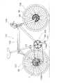
図1において、本発明の一実施形態を採用した自転車101は、サスペンションフォーク98を有するダイヤモンド形のフレーム102と、サスペンションフォーク98に固定されたハンドル104と、チェーン95やペダルPDが装着されたギアクランク96や電動リアディレーラ(電動変速装置の一例)97等からなる駆動部105と、サスペンションフォーク98及びフレーム後部に装着され、スポーク99を有する前輪及び後輪106,107とを備えている。後輪107にはハブダイナモ(発電ハブの一例)1が設けられている。 In FIG. 1, a
〔ハブダイナモの構成〕
図2において、本発明の一実施形態によるリアハブ1は、自転車の後輪107に設けられるリアハブであり、自転車の後輪107とともにフレーム102のチェーンステイ102aの後端に装着されるものである。このリアハブ1は、チェーンステイ102aの後端部に両端が固定されたハブ軸5と、ハブ軸5の外周側に配置されたハブ体6と、ハブ体6をハブ軸5に対して回転自在に支持するための1対の軸受7a,7bと、ハブ体6とハブ軸5との間に配置され両者の相対回転により発電する発電機構8と、発電機構8により発電された電力を蓄える充電部9と、ハブ体6の図2右側面設けられたフリーホイール10と、充電部9に蓄えられた電力を外部に出力可能な電力出力端子(電力出力部の一例)11とを備えている。[Configuration of Hub Dynamo]
In FIG. 2, the
ハブ軸5は、たとえばクロムモリブデン鋼製の筒状部材であり、その両端がクイックレリーズ機構50によってフレーム102後端部に容易にできるように着脱できるように固定されている。クイックレリーズ機構50は、カムレバー51と、ナット52と、両端にレバー及びナット51,52が螺合する連結軸53とを有する公知のものである。ハブ軸5には、内部をクイックレリーズ機構50の連結軸53が貫通しており、外周面の3箇所に左端から順に雄ねじ部5a〜5cが形成されている。雄ねじ部5aは軸受7aの玉押し(後述)を装着すると共に発電機構8の内側固定ユニット(後述)を固定するためのものである。雄ねじ部5bは、内側固定ユニットを固定するためのものである。雄ねじ部5cは、軸受7bの玉押し(後述)を装着するためのものである。ハブ軸5の右端部には、電力出力端子11が回転不能に装着されている。また、ハブ軸5の外周面には電力出力用の接続コード35a,35bを通すためのコード通過溝5dが発電機構8装着部分から図2右端にかけて形成されている。コード通過溝5dを挟んでハブ軸5の雄ねじ部5aが形成された外周面には、互いに平行な面取り部5e(図9)が形成されている。ここで、接続コード35aは、発電機構8と充電部9とを接続するための配線であり、接続コード35bは、充電部9と電力出力端子11とを接続するための配線である。 The
ハブ体6は、たとえば軽量なアルミニウム合金製の部材であり、開口12dを図2右側面側に有する筒状ケース本体12と、ケース本体12の開口12dを覆うようにケース本体12に着脱自在に装着された蓋部材13とを有している。ケース本体12の外周面には軸方向に間隔を隔てて配置された1対のハブフランジ12a,12bが形成されている。このハブフランジ12a,12bにスポーク99が連結されている。ケース本体12の開口12dは、発電機構8を組み付け可能な大きさを有しており、そこには、蓋部材13を装着するための雌ねじ部12eが形成されている。ケース本体12の左端部には、ディスクブレーキ55のディスクロータ55aを装着可能なブレーキ装着部12cが設けられている。 The
蓋部材13は、ケース本体12の雌ねじ部12eに螺合する雄ねじ部13dを外周に有する外筒部13aと、外筒部13aの内周側に間隔を隔てて配置された内筒部13bと、両筒部13a,13bを連結する連結部13cとが一体形成された部材である。内筒部13bの内周面には、フリーホイール10を連結するための連結ボルト44が螺合している。 The
軸受7aは、ケース本体12とハブ軸5との間に装着されている。軸受7aは、ケース本体12の左端内周面に設けられた玉受け14aと、ハブ軸5の雄ねじ部5aに螺合する玉押し14bと、玉押し14bと玉受け14aとの間に両者にそれぞれ接触して転動するボール14cとを有している。軸受7bは、フリーホイール10とハブ軸5との間に配置されている。軸受7bは、フリーホイール10に設けられた玉受け15aと、ハブ軸5の雄ねじ部5cに螺合する玉押し15bと、玉押し15bと玉受け15aとの間に両者にそれぞれ接触して転動するボール15cとを有している。ボール14c,15cの周囲にはグリースが充填されている。 The bearing 7 a is mounted between the
発電機構8は、ケース本体12に固定された永久磁石16と、ハブ軸5に固定された内側固定ユニット17とを有している。 The
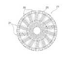
永久磁石16は、図2に示すように、ケース本体12の内面に固定されており、円周方向に等間隔に分割された4個の磁石体から構成されている。この永久磁石16には、等間隔で交互にN極とS極とが着磁されており、それぞれが後述するヨーク外周部と対抗している。 As shown in FIG. 2, the
内側固定ユニット17は、リング状のコイル20と、コイル20の周囲を囲むように設けられたヨーク21とを有している。そして、これらのコイル20及びヨーク21は、ハブ軸5の外周に形成された雄ねじ部5a,5bに螺合する1対のナット22a,22bにより挟まれるようにしてハブ軸5に固定され、かつ軸方向において永久磁石16に対向するような位置関係に位置決めされている。 The inner fixing unit 17 includes a ring-shaped
コイル20は、図3に示すようなボビン25に巻かれている。ボビン25は、図3及び図3の拡大部分図である図4に示すように(図3、図4ともに、ヨークは取り外して示している)、外周にコイル20が巻かれた筒状の胴部26と、胴部26の軸方向両端部に形成された第1フランジ27及び第2フランジ28とを有している。第1及び第2フランジ27,28において、軸方向外側の側面には、ほぼ放射状に延びる複数の溝27a,28aが形成されている。これらの溝27a,28aは、外周側では、軸方向視で互いにずれるように、すなわち、第1フランジ27の隣接する2つの溝27aの間に第2フランジ28の溝28aが位置するように、また半径方向のほぼ中間部においては両溝27a,28aが軸方向視で部分的に重なるように、さらに、内周側では、両溝27a,28aの軸方向視でほぼ全部が重なるように形成されている。そして、各溝27a,28aの外周側一部は、切り欠かれて切欠部27b,28bとなっている。また、各フランジ27,28の外周面において、溝27a,28aが形成されていない部分には、図4及び図4の斜視部分図である図5に示すように、軸方向の内側から外側に所定長さの複数の凹部27c,28cが形成されている。なお、図5では、説明の便宜のために、一部のヨークを取り外して示している。 The
図6にボビン25に装着されたヨーク21を示し、図7及び図8にヨーク21のみを取り出して示す。このヨーク21は、図5及び図6に示すように、ボビン25の第1フランジ27の溝27aに嵌め込むようにして装着された複数組の第1積層ヨーク30と、同様にボビン25の第2フランジ28の溝28aに嵌め込むようにして装着された複数組の第2積層ヨーク31とを有している。 6 shows the
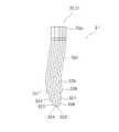
各積層ヨーク30,31は、図7及び図8に示すような複数の板状積層片32を積層することにより構成されている。各積層片32は、表面に酸化被膜が形成されている珪素鋼板(より詳しくは無方向性珪素鋼板)で形成されている。各積層片32の基本的な形状は同じであり、ヨーク外周部32aと、ヨーク内周部32bと、連結部32cとを有している。ヨーク外周部32aは、連結部32cの一方の端部からハブ軸5の軸方向(図7におけるO−O方向)に沿って延びるように設けられ、先端側にいくにしたがって細くなるような形状である。また、ヨーク内周部32bは、連結部32cの他方の端部から同様に軸方向に沿って延びて設けられている。そして、これらの積層片32は、図8に示すように、軸方向視で、ヨーク外周部32aとヨーク内周部32bとが異なる放射線上に位置するように形成されている。Each of the
また、各積層片32の厚みは0.25〜1mmのものが使用され、0.5mmのものがコスト的にも性能的にも利用価値が高い。各積層片32は長さが異なっている。すなわち、各積層ヨーク30,31は、8枚の積層片32を積層することによって構成されているが、各積層ヨーク30,31において、図8に示すように、最も外側の1対の積層片321,328は内周側の長さが最も短く、その内側の1対の積層片322,327はその次に短く、さらにその内側の1対の積層片323,326はその次に短く、最も内側の1対の積層片324,325は最も長く形成されている。このような長さに設定することによって、円周方向において隣接する積層ヨークの内周部が互いに接触しないように、かつ磁路の断面積が最も広くとれるような効率の良い構成とすることができる。 Further, the thickness of each
さらに、図5から明らかなように、各積層ヨーク30,31を構成する積層片32のうち、円周方向の両外側に位置する積層片321,328は、ヨーク外周部32aの長さが他の積層片と比較してほぼ1/2程度に短く形成されている。これは、円周方向において隣接する積層片321,328同士が近接するのを防止し、両者の間で磁束が漏れるのを抑えるためである。また、各積層ヨーク30,31は、両フランジ27,28よりハブ軸方向外方に突出している。Further, as is apparent from FIG. 5, among the
さらにまた、図7から明らかなように、各積層片32は、ヨーク外周部32aと連結部32cとを接続する部分の外側(図7におけるP部分)が、円弧形状ではなく、鋭角状に形成されている。したがって、この部分においても永久磁石16との距離が近くなり、従来の板金プレスによって形成されたヨークに比較して磁束量が増えることになる。Furthermore, as is apparent from FIG. 7, each
なお、以上のような各積層片32は、第1積層ヨーク30及び第2積層ヨーク31に共通で用いることができる。 Each
このような積層片32は積層されて、ボビン25の各フランジ27,28に形成された溝27a,28aに嵌め込まれている。また、各積層片32のヨーク外周部32aの先端部は、ボビン25の対向する側のフランジ27,28に形成された凹部27c,28cに嵌め込まれて保持されている。 Such
このようなヨーク21によって、図2に示すように、コイル20の内周側に第1及び第2積層ヨーク30,31のヨーク内周部32bが位置し、コイル20と永久磁石16との間にヨーク外周部32aが位置することになる。また、図5及び図2から明らかなように、第1積層ヨーク30と第2積層ヨーク31のヨーク内周部32bは、互いに直接的に接続されることになる。したがって、第1積層ヨーク30と第2積層ヨーク31とを接続するための他の磁性材料からなる部材が不要となり、抵抗を非常に小さく抑えることができる。 With such a
なお、図2に示すように、コイル20及びヨーク21を固定するためのナット22a,22bのヨーク21側には、ワッシャ23a,23bが装着されている。このうち、ワッシャ23bは、図9に示すように、ハブ軸5の面取り部5eに係合する互いに平行な面を有する略長円形の係止孔23cを有しており、ハブ軸5に回転不能に係止される。また、ワッシャ23bには、第1積層ヨーク30の突出部分に係止される突起部23dが第1フランジ27に向けてプレス加工により突出して形成されている。さらに、ワッシャ23bには、コイル20から導出される接続コード35aを通すためのスリット23eが、係止孔23cのコード通過溝5dに対向する位置から径方向外方に切り欠いて形成されている。 As shown in FIG. 2,
これによりワッシャ23bは、内側固定ユニット17をハブ軸5に対して回り止めできるので、コイル20から取り出された接続コード35aをコード通過溝5dに確実に案内できる。この接続コード35aは、充電部9に接続されている。 Accordingly, the
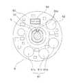
充電部9は、図2に示すように、発電機構8とともにハブ軸5に固定されている。具体的には、充電部9は、図2及び図10に示すように、ワッシャ状の回路基板60を有しており、回路基板60がワッシャ23bとナット22bとの間に絶縁ワッシャ56を介してハブ軸5に回転不能に装着されている。 As shown in FIG. 2, the charging unit 9 is fixed to the
回路基板60には、図10及び図11に示すように、たとえば3つの電気二重層コンデンサ61aからなる蓄電素子61と、たとえば半波整流回路を含む充電制御回路62とが搭載されている。また、回路基板60には、たとえば、ツェナーダイオードを用いた波形成形回路(速度信号生成部の一例)63と、蓄電素子61及び波形成形回路63に接続された速度重畳回路64とが搭載されている。 As shown in FIGS. 10 and 11, the
充電制御回路62は、発電機構8で発電された交流電力を整流して直流に変換し、蓄電素子61に充電するための回路である。波形成形回路63は、発電機構8で発電された電力から発電周波数に応じたパルス信号を生成するものである。このパルス信号のパルス幅は、マイクロコンピュータをリセットしない程度の短いものである。このパルス信号の周期と車輪径とにより速度や走行距離を検出できる。速度重畳回路64は、波形成形回路63から出力されたパルス信号で蓄電素子61からの出力をオンオフし、直流の電力に速度信号を重畳するものである。これにより、電力を外部に出力する接続コード35bを介して速度信号を外部に出力できる。回路基板60には、発電機構8に接続された接続コード35a及び電力出力端子11に接続される接続コード35bを接続するための雄コネクタ66が装着されている。各接続コード35a,35bには、雄コネクタ66に電気的に着脱自在に接続される雌コネクタ67が設けられている。 The
フリーホイール10は、図2に示すように、ハブ体6の蓋部材13の内周側側面に回転不能に連結されたベース部41と、ベース部41に回転自在に装着されたギア取付部42と、ベース部41とギア取付部42との間に配置されたワンウェイクラッチ43とを有している。 As shown in FIG. 2, the
前述したようにベース部41は、内筒部13bの内周面にねじ込まれた筒状の連結ボルト44により内筒部13bと連結されている。連結ボルト44は頭部でベース部41を係止している。また、内筒部13bとベース部41とは連結ボルト44の外周側で両者の間に配置された連結部材45により回転不能に連結されている。連結部材45の外周面にはセレーションが形成されており、連結部材45は内筒部13bに形成されたセレーションに圧入されている。この圧入された連結部材45のセレーションがベース部41の一端内周面に形成されたセレーションに噛み合っている。これにより、内筒部13bとベース部41とが回転不能に強固に連結されている。 As described above, the
ベース部41は筒状の部材であり、そこには、軸受7bの玉受け15aがねじ込まれている。玉受け15aはギア取付部42を支持するための軸受の玉押しと兼用されている。 The
また、ベース部41には、ワンウェイクラッチ43を構成する爪部材43aが起伏自在に装着されている。ワンウェイクラッチ43はギア取付部42に装着された多段ギア54(すなわちペダル)の進行方向の回転のみベース部41に伝達するとともに、後輪107の進行方向の回転を多段ギア54に伝達しないようにするためのクラッチである。爪部材43aはバネ部材43bにより起きる方向に付勢されている。爪部材43aは、ギア取付部42が進行方向に回転すると、ギア取付部42の内周面に形成されたラチェット歯43cに噛み合ってギア取付部42からベース部41に回転を伝達する。ギア取付部42は筒状の部材であり、外周に多段ギア54が着脱自在かつ回転不能に装着される。 Further, a
電力出力端子11は、ハブ軸5に回転不能に装着されている。この実施形態では、コード配線溝5dを通って配線された接続コード35bをリアディレーラ97に電気的に使用するために使用される。電力出力端子11からは、速度信号が重畳された直流電力が出力される。 The
次に、リアハブ1の動作について説明する。 Next, the operation of the
自転車のペダルPDをこぐとギアクランク96の回転がチェーン95を介して多段ギア54に伝達され、ギア取付部42が回転する。この回転がワンウェイクラッチ43を介してベース部41に伝達されハブ体6が回転し、後輪107が進行方向に回転する。走行中にペダルをこぐのを止めるとワンウェイクラッチ43がオフして後輪107が回転してもその回転がギア取付部42に伝達されず、ギアクランク96は回転しない。しかし、ハブ軸5とハブ体6とが相対回転する。 When the pedal PD of the bicycle is stepped on, the rotation of the gear crank 96 is transmitted to the
ハブ軸5に対して後輪107すなわちハブ体6が回転すると、ハブ軸5に固定されている内側固定ユニット17に対して永久磁石16が回転する。これにより、コイル20及びヨーク21のヨーク外周部32aの外周側を永久磁石16が回転することになる。 When the
ここで、第1積層ヨーク30のヨーク外周部32aと、第2積層ヨーク31の外周部32aとは、一方が永久磁石16からN極の磁束供給を受けるときには他方がS極の磁束供給を受け、一方が永久磁石16からS極の磁束供給を受けるときには他方がN極の磁束供給を受ける。すなわち、第1及び第2積層ヨーク30,31のヨーク外周部32aの外周側を永久磁石16が回転することにより、第1積層ヨーク30がN極で第2積層ヨーク31がS極である第1状態、及び第1積層ヨーク30がS極で第2積層ヨーク31がN極である第2状態が繰り返されて、両者30,31を磁気的に連結している両積層ヨーク30,31のヨーク内周部32bに交番磁束が発生する。このコイル20の内側に発生する交番磁束によって、コイル20に電流が発生し、発電がされる。 Here, when one of the outer
この実施形態によるリアハブ1では、ヨーク21を板状の積層片32を積層して構成しているので、従来の板金プレス成形によって構成した場合に比較して、渦電流の発生を抑えることができる。 In the
また、本実施形態のように、クローポール構造では、ヨーク部分を単純に積層構造に置き換えただけでは、対向するヨーク同士を接続するために他の磁性材料を必要とし、そのために磁気抵抗が増加して効率が低下する。しかし、本実施形態では、ヨークの形状を工夫し、対向する第1及び第2積層ヨークの内周側部分を互いに直接的に接続可能としたので、第1及び第2積層ヨークを接続するための他の部材が不要となり、しかも磁束が通過するのに必要充分な断面積を確保することができる。したがって、磁気抵抗を非常に小さくでき、効率を向上することができる。 In addition, as in this embodiment, in the claw pole structure, simply replacing the yoke part with a laminated structure requires another magnetic material to connect the opposing yokes, which increases the magnetic resistance. Efficiency is reduced. However, in the present embodiment, the shape of the yoke is devised so that the inner peripheral side portions of the opposed first and second laminated yokes can be directly connected to each other, so that the first and second laminated yokes are connected. Other members are not required, and a sufficient cross-sectional area for allowing the magnetic flux to pass can be ensured. Therefore, the magnetic resistance can be made very small and the efficiency can be improved.
発電された電力は、充電部9に出力され、充電部9の充電制御回路62で整流されて直流電力に変換され蓄電素子61に蓄えられる。また、波形成形回路63で自転車の速度に応じた周期のパルス信号が生成され、そのパルス信号により蓄電素子61からの直流電力がオンオフされ、速度信号が重畳した直流電力が接続コード35aを経由して電力出力端子11から出力される。ここでは、リアハブ1は後輪107に設けられているので、ランプ以外の後輪からの距離が短い電装品に対して電力の供給を短い距離で行え、電力を効率良く供給できる。また、後輪107のリアハブ1からはケーブルの配索本数が少ないので、配線を後輪107のリアハブ1から電装品に行うことにより電装品の配線を行いやすくなる。また、リアハブ1に充電部9を設けてそこに蓄えられた電力を出力するようにしたので、自転車101が停止しても電力を電動リアディレーラ97などの電装品に出力することができる。このため、発生した電力を走行状態に係わらず安定して利用できる。 The generated power is output to the charging unit 9, rectified by the charging
〔電動ディレーラの構成〕
電動リアディレーラ97は、リアハブ1に装着された複数のスプロケットを有する多段ギア54のいずれかのスプロケットにチェーンを案内して変速するものである。電動リアディレーラ97は、図12及び図13に示すように、チェーンステイ102aの後端に設けられたディレーラ取付部102b(図1)に装着されるベース部材70と、ベース部材70に対して移動する可動部材71と、ベース部材70と可動部材71とを移動可能に連結するリンク機構72と、可動部材71に揺動自在に装着されるチェーンガイド73と、リンク機構72を制御する駆動ユニット74とを備えている。[Configuration of electric derailleur]
The electric
ベース部材70は、六角穴付きボルト80によりディレーラ取付部102bに固定される。ベース部材70は、ディレーラ取付部102bに装着されるボス部81a及びアーム部81bを有する主フレーム81と、主フレーム81にボルトにより装着される副フレーム82とを有している。この主フレーム81と副フレーム82とに挟まれて駆動ユニット74が配置されている。主フレーム81には、リアハブ1の電力出力端子11とを配線により接続するための配線接続部85が設けられている。この配線接続部85と電力出力端子11とを配線により接続することにより電動リアディレーラ97に電力及び速度信号が与えられ、電動リアディレーラ97が動作する。 The
可動部材71は、リンク機構72に連結されており、駆動ユニット74によりリンク機構72が駆動されると、チェーンステイ102aと接離する方向に移動する。可動部材71には、チェーンガイド73が揺動自在かつチェーン95に張力を付与する方向(図12時計回りに)に付勢された状態で装着されている。 The
リンク機構72は、一端が駆動ユニット74に連結され、他端が可動部材71に連結された1対のリンク83,84を有している。リンク83,84は互いに平行に配置されており、駆動ユニット74に連結された一端が回動すると、他端に設けられた可動部材71がチェーンステイ102aと接離する方向に平行移動する。 The
チェーンガイド73は、可動部材71に揺動自在に装着された第1プレート部材90と、第1プレート部材90の外側に間隔を隔てて配置された第2プレート部材91と、第1及び第2プレート部材90,91の基端に回転自在に装着されたガイドプーリ92と、第1及び第2プレート部材90,91の他端に回転自在に装着されたテンションプーリ93とを有している。両プレート部材90,91は、各プーリ92,93を取り付けるボルトにより固定されている。第1プレート部材90のガイドプーリ92と対向する位置には、たとえば、リードスイッチからなるプーリセンサ94が装着されている。また、ガイドプーリ92のプーリセンサ94に対向する位置には、検出子としての磁石94aが埋め込まれている。これにより、ガイドプーリ92が回転しているか否かを検出している。このガイドプーリ92の回転は、チェーン95の移動に連動するため、ギアクランク96の回転を検出できる。ディレーラ97は、ギアクランク96が回転していないときに変速すると不具合が生じるため、このプーリセンサ94の出力により変速制御を行える状態か否かの判断をする。 The
駆動ユニット74は、主フレーム81及び副フレーム82により挟持され以下の各部を収納するケース部材75と、リンク機構72をモータ76により駆動するモータユニット77と、モータ76を駆動するモータ駆動回路78と、モータユニット77により駆動されるチェーンガイド73の変速位置を検出するための変速位置センサ79と、位置補正メモリ86とを有している。また、駆動ユニット74は、プーリセンサ94、リアハブ1から得られる速度信号、及び変速位置センサ79の出力によりモータ駆動回路78を介してモータ76を制御する変速制御部87を有している。 The
モータユニット77は、リンク機構72のリンク83に連結されており、モータ76の回転を減速してリンク83を揺動させる。変速位置センサ79は減速されたモータユニットの回転位置を検出する。このため、変速位置センサ79の検出された回転位置とチェーンガイド73の変速位置とは比例した関係にならない。このため、位置補正メモリ86が必要になる。位置補正メモリ86には、チェーンガイド73の変速位置と、変速位置センサ79が検出した回転位置との関係がたとえばテーブル形式で記憶されている。 The
変速制御部87は、たとえば、CPU,I/Oインターフェイス、RAM,ROMとを含むマイクロコンピュータで構成され、前述したように、主に速度信号により電動リアディレーラ97を自動変速制御する。この、電動リアディレーラ97と、リアハブ1と、充電部9と、変速制御部87とで変速システム88が構成される。 The
このような変速システム88では、リアハブ1に発電機構8及び充電部9を設けるとともに、電動リアディレーラ97に変速制御部87を設けたので、リアハブ1と電動リアディレーラ97とを自転車101に装着し、それらを配線で接続するだけで変速システム88を動作させることができる。ここでは、リアハブ1と電動リアディレーラ97以外の余分なものを自転車10に装着することなく電源の交換を行う必要がない変速システム88が動作するので、自転車の組立工数や配線工数を削減できるとともに、外観の変化も少なくなる。このため、この変速システム88を自転車101に装着しても、自転車101の製造コストを低く抑えることができるとともに、自転車101の外観を損ねにくい。 In such a transmission system 88, the
次に、変速制御部87の変速制御動作について、図14及び図15に示す制御フローチャートに基づいて説明する。 Next, the shift control operation of the
ライダーが自転車101を走行させ、発電機構8から発電された電力により蓄電素子61が電力を十分に蓄えると、自転車1の変速制御が可能となる。これにより、まず、図14のステップS1にて変速制御部87の初期設定を行う。この初期設定では、変数OPを「1」に初期化する。OPは、変速段の値であり、図示しないメモリには、変速段OPごとのシフトアップしきい値U(OP)及びシフトダウンしきい値D(OP)が車速の値で記憶されている。 When the rider runs the
ステップS2では、リアハブ1からの速度信号をもとに算出した車速Vを取り込む。ステップS3では、設定された変速段OPを取り込む。これは、変速位置センサ79の出力を元に位置補正メモリ86からのデータを読み出して取り込む。ステップS4では、取り込んだ車速Vが変速段毎のシフトアップしきい値U(OP)を上回っているか否かを判断する。ステップS5では、取り込んだ車速Vが変速段毎のシフトダウンしきい値D(OP)を下回っているか否かを判断する。取り込んだ車速Vが変速段毎のシフトアップしきい値U(OP)を上回っていると判断すると、ステップS4からステップS6に移行し、プーリセンサ94からの出力によりギアクランク96が回転している、つまりライダーがペダルPDを踏んでいるか否かを判断する。ギアクランク96が回転していると判断すると、ステップS7に移行する。ステップS7では、図15に示すシフトアップ処理を実行する。ギアクランク96が回転していないと判断すると、シフトアップ処理を行わずにステップS5に移行する。 In step S2, the vehicle speed V calculated based on the speed signal from the
取り込んだ車速Vが変速段毎のシフトダウンしきい値D(OP)を下回っていると判断すると、ステップS5からステップS8に移行し、ステップS6と同様に、プーリセンサ94の出力により、ギアクランク96が回転しているか否かを判断する。ギアクランク96が回転していると判断すると、ステップS9に移行する。ステップS9では、図16に示すシフトダウン処理を実行する。ギアクランク96が回転していないと判断すると、シフトアップ処理を行わずにステップS2に戻る。 If it is determined that the captured vehicle speed V is below the shift-down threshold value D (OP) for each gear position, the process proceeds from step S5 to step S8, and the gear crank 96 is output by the output of the
ステップS7のシフトアップ処理では、図15のステップS11で現在の変速段OPを1段分インクリメントして目標変速段を設定する。ステップS12では、モータ76が正転動作中であるか否かを判断する。これにより、電動リアディレーラ97がシフトアップ方向に変速動作中であるか否かを判断する。モータ76が正転動作していない場合、つまりシフトアップ変速動作中でない場合にはステップS13に移行し、モータ76を正転動作させるとともに変速位置センサ79の位置データSHの取込を開始する。モータ97がすでに正転動作している場合にはこの処理をスキップする。 In the upshift process of step S7, the current gear stage OP is incremented by one stage in step S11 of FIG. 15, and the target gear stage is set. In step S12, it is determined whether or not the
ステップS14では、位置データSHが設定された目標変速段に達したか否か、つまり変速動作を終了してもよいか否かを判断する。変速動作を終了してもよいと判断するとステップS15に移行し、変速モータをオフするとともに変速位置センサの位置データの取込を終了する。 In step S14, it is determined whether or not the position data SH has reached the set target shift speed, that is, whether or not the shift operation can be terminated. If it is determined that the speed change operation may be terminated, the process proceeds to step S15, where the speed change motor is turned off and the position data of the speed change position sensor is terminated.
ここでは、変速動作中であっても最初にステップS11で目標変速段を新たに設定して以前に設定された目標変速段を更新している。 Here, even during the shift operation, first, the target shift speed is newly set in step S11 and the previously set target shift speed is updated.
ステップS9のシフトダウン処理では、図16のステップS21で現在の変速段OPを1段分デクリメントして目標変速段を設定する。ステップS22では、モータ76が逆転動作中であるか否かを判断する。これにより、電動リアディレーラ97がシフトダウン方向に変速動作中であるか否かを判断する。モータ76が逆転動作していない場合、つまりシフトダウン変速動作中でない場合にはステップS23に移行し、モータ76を逆転動作させるとともに変速位置センサ79の位置データSHの取込を開始する。モータ76がすでに逆転動作している場合にはこの処理をスキップする。 In the downshift process in step S9, the current gear stage OP is decremented by one stage in step S21 in FIG. 16, and the target gear stage is set. In step S22, it is determined whether or not the
ステップS24では、位置データSHが設定された目標変速段に達したか否か、つまり変速動作を終了してもよいか否かを判断する。変速動作を終了してもよいと判断するとステップS25に移行し、モータ76をオフするとともに変速位置センサ79の位置データSHの取込を終了する。 In step S24, it is determined whether or not the position data SH has reached the set target shift speed, that is, whether or not the shift operation can be terminated. If it is determined that the shift operation may be terminated, the process proceeds to step S25, where the
ここでもシフトアップ処理と同様に、変速動作中であっても最初にステップS21で目標変速段を新たに設定して以前に設定された目標変速段を更新している。 Here, similarly to the shift-up process, even during the shift operation, first, the target shift speed is newly set in step S21 and the previously set target shift speed is updated.
このような自動変速制御を行う場合、従来は、リアハブから出力された電力を自転車に装着された充電回路により整流して直流に変換し、車速センサから取り込んだ車速に応じて同じく自転車に装着された変速制御部によりディレーラ等の変速装置を制御している。 When performing such automatic shift control, conventionally, the electric power output from the rear hub is rectified by a charging circuit mounted on the bicycle and converted to direct current, and the same is mounted on the bicycle according to the vehicle speed taken from the vehicle speed sensor. A transmission device such as a derailleur is controlled by the transmission control unit.
しかし、本実施形態では、リアハブ1内に充電部9を設けリアハブ1内で交流を直流に変換して出力しているので、充電回路が不要になる。また、変速制御部87がリアディレーラ97に装着されているので、変速制御部を別に設ける必要がない。このため、配線としては、リアハブ1の電力出力端子11と電動リアディレーラ97の配線接続部85とを用意すればよい。しかも、リアハブ1内で速度信号を電力に重畳して出力するので、配線として2芯の線を用意するだけでよい。このため、自転車組み立て時の配線作業が飛躍的に簡素化される。また、自転車101にリアハブ1と電動リアディレーラ97とを装着するだけでよいので、部品の装着作業も簡素化され、自転車の組み立てコストが飛躍的に低減する。 However, in this embodiment, since the charging unit 9 is provided in the
〔他の実施形態〕
(a)前記実施形態では、電動変速装置として電動リアディレーラを例示したが、充電機能を有する電動内装変速ハブを用いてもよい。すなわち、内装変速ハブの内部に前記実施形態と同様な発電機構を装着するとともに、ハブ軸にモータユニットとモータ駆動回路と変速制御部とをたとえばケース等に収納して装着すればよい。このような内装変速ハブの場合、ハブを自転車に装着するだけで自動変速制御を行うことができる。[Other Embodiments]
(A) In the above embodiment, the electric rear derailleur has been exemplified as the electric transmission, but an electric internal transmission hub having a charging function may be used. That is, a power generation mechanism similar to that of the above-described embodiment may be mounted inside the internal transmission hub, and the motor unit, the motor drive circuit, and the shift control unit may be housed and mounted on the hub shaft, for example in a case. In the case of such an internal transmission hub, automatic transmission control can be performed simply by mounting the hub on a bicycle.
(b)前記実施形態では、充電部9をリアハブ1内に設け、変速制御部87を電動リアディレーラ97に設けたが、両方ともリアハブ1に設けてもよく、また電動リアディレーラに設けてもよい。ただし、その他の電装品の電源として発電機構8の出力を利用したり、速度信号を利用したりする場合、前記実施形態のように配置するのが好ましい。 (B) In the above embodiment, the charging unit 9 is provided in the
(c)前記実施形態では、発電機構8をリアハブ1内に配置したが、リアハブの外部に配置してもよい。この場合、充電部等もハブの外部に配置してもよい。 (C) Although the
(d)前記実施形態では、自動変速処理だけを行うようにしたが、ハンドル部に変速操作部を設け、変速操作部と電動リアディレーラ97とを電気的に接続して手動変速を行えるようにしてもよい。この場合でも、変速操作部の装着と、変速操作部と電動リアディレーラとの間の配線だけを行えばよいので、従来に比べて装置の装着作業や配線作業が簡素化する。 (D) In the above-described embodiment, only the automatic shift process is performed. However, a shift operation unit is provided in the handle unit, and the shift operation unit and the electric
1 リアハブ
5 ハブ軸
6 ハブ体
7 軸受
8 発電機構
9 充電部
10 フリーホイール
11 電力出力端子
16 永久磁石
17 内側固定ユニット
20 コイル
21 ヨーク
25 ボビン
27,28 フランジ
30,31 第1及び第2積層ヨーク
32 積層片
32a ヨーク外周部
32b ヨーク内周部
60 回路基板
61 蓄電素子
61a 電気二重層コンデンサ
62 充電制御回路(整流回路の一例)
63 波形成形回路(速度信号生成部の一例)
64 速度重畳部(信号重畳部の一例)
70 ベース部材
71 可動部材
72 リンク機構
73 チェーンガイド
74 駆動ユニット
78 モータ駆動回路
87 変速制御部
90,91 第1及び第2プレート部材
92 ガイドプーリ
93 テンションプーリ
94 プーリセンサ
97 電動リアディレーラ(電動変速装置の一例)
98 サスペンションフォーク
101 自転車
102 フレーム
106 前輪
107 後輪DESCRIPTION OF
63 Waveform shaping circuit (an example of a speed signal generator)
64 Speed superimposing unit (an example of a signal superimposing unit)
98
Claims (14)
Translated fromJapanese前記フレームの後部に装着される電気駆動される電動変速装置と、
車輪の回転により発電する発電機構と、前記フレームの後部に装着されるハブ軸と、を有するリアハブと、
前記リアハブ及び前記電動変速装置のいずれかに設けられ、前記発電機構で発生した電力を蓄える充電部と、
前記リアハブ及び前記電動変速装置のいずれかに設けられ、前記充電部に蓄えられた電力により前記電動変速装置を変速制御する変速制御部と、を備え、
前記充電部は、前記ハブ軸に装着され前記ハブ軸が貫通可能な座金形状の回路基板を有し、
前記回路基板は、前記発電機構とともにナットにより前記ハブ軸に固定されている、自転車用変速システム。A bicycle transmission system mounted on the rear part of a bicycle frame,
An electrically driven electric transmission mounted on the rear of the frame;
A rearhub having a power generation mechanism that generates electric power by rotation of a wheel, and ahub shaft that is attached to a rear portion of the frame;
A charging unit that is provided in any of the rear hub and the electric transmission, and stores electric power generated by the power generation mechanism;
A shift control unit that is provided in any of the rear hub and the electric transmission, and that controls the shift of the electric transmission with the electric power stored in the charging unit;
The charging unit has a washer-shaped circuit board that is attached to the hub shaft and through which the hub shaft can pass.
The bicycle transmission system, wherein the circuit board is fixed to the hub axle by a nut together with the power generation mechanism .
前記フレームに装着されるベース部材と、
前記ベース部材に対して移動する可動部材と、
前記ベース部材と前記可動部材とを移動可能に連結するリンク機構と、
前記可動部材に揺動自在に装着され、基端に装着されたガイドプーリと、先端に装着されたテンションプーリとを有するチェーンガイドと、
前記リンク機構を駆動する駆動ユニットとを有する電動リアディレーラである、請求項1から4のいずれか1項に記載の自転車用変速システム。The electric transmission is
A base member attached to the frame;
A movable member that moves relative to the base member;
A link mechanism for movably connecting the base member and the movable member;
A chain guide that is swingably attached to the movable member and has a guide pulley attached to the base end and a tension pulley attached to the tip;
The bicycle transmission system according to any one of claims 1 to4 , wherein the bicycle transmission system is an electric rear derailleur having adrive unit that drives the link mechanism.
前記フレームの後部に装着される前記ハブ軸と、
前記ハブ軸の外周に配置されるハブ体と、
前記ハブ体を前記ハブ軸に対して回転自在に支持するための軸受と、
前記発電機構と、
前記充電部と、
前記充電部に蓄えられた電力を外部に出力可能な電力出力部と、
前記ハブ体に対して自転車の進行方向の回転のみ伝達可能なフリーホイールと、
を備えた、請求項2から7のいずれか1項に記載の自転車用変速システム。The rear hub is
Said hub axle that is mounted to the rearof said frame,
A hub body arranged on an outer periphery of the hub shaft;
A bearing for rotatably supporting the hub body with respect to the hub shaft;
The power generation mechanism;
The charging unit;
A power output unit capable of outputting the power stored in the charging unit to the outside;
A freewheel capable of transmitting only rotation in the traveling direction of the bicycle to the hub body;
The bicycle transmission system according to any one of claims 2 to 7, further comprising:
前記充電部は、
前記発電機構で発電された交流を直流に変換する整流回路と、
前記整流された直流電力を蓄える蓄電素子とを有する、請求項8に記載の自転車用変速システム。The power generation mechanism generates AC power by rotating the wheel,
The charging unit is
A rectifier circuit that converts alternating current generated by the power generation mechanism into direct current;
The bicycle transmission system according to claim 8, further comprising a storage element that stores the rectified DC power.
前記電力出力部は、前記速度検出用の信号が重畳された電力を出力する、請求項9から11のいずれか1項に記載の自転車用変速システム。A speed superposition circuit that superimposes the electric power stored in the power storage element and the speed detection signal generated by the speed signal generation unit;
The bicycle transmission system according to any one of claims 9 to 11, wherein the power output unit outputs electric power on which the speed detection signal is superimposed.
前記ハブ体の内周面に設けられた永久磁石と、
前記永久磁石の内周側に配置され、前記ハブ軸に固定された内側固定ユニットとを有する、請求項8から12のいずれかに記載の自転車用変速システム。The power generation mechanism is
A permanent magnet provided on the inner peripheral surface of the hub body;
The bicycle transmission system according to any one of claims 8 to 12, further comprising an inner fixing unit that is disposed on an inner peripheral side of the permanent magnet and is fixed to the hub shaft.
前記永久磁石の内周側に配置されたリング状のコイルと、
前記コイルの軸方向一方側に設けられたそれぞれが複数の板状積層片からなる複数組の第1積層ヨークと、前記コイルの軸方向他方側に設けられたそれぞれが複数の板状積層片からなる複数組の第2積層ヨークとを有し、前記コイルの周囲を囲むように配置されたヨークとを備え、
前記複数の板状積層片のそれぞれは、連結部と、連結部の外周側の端部から前記ハブ軸の軸方向に沿って延び前記永久磁石とコイルとの間に配置されたヨーク外周部と、前記連結部の内周側の端部から前記ハブ軸の軸方向に沿って延びるヨーク内周部とを有し、
複数組の前記第1及び第2積層ヨークは、それぞれの前記ヨーク内周部が軸方向に対向し、かつ前記ヨーク外周部は円周方向に交互に位置するように設けられている、請求項12に記載の自転車用変速システム。The inner fixing unit is
A ring-shaped coil disposed on the inner peripheral side of the permanent magnet;
A plurality of sets of first laminated yokes each provided on one side in the axial direction of the coil and a plurality of first laminated yokes each formed on the other side in the axial direction of the coil A plurality of sets of second laminated yokes, and a yoke arranged to surround the coil,
Each of the plurality of plate-like laminated pieces includes aconnecting portion, and a yoke outer peripheral portionextending betweenan end portion on the outer peripheral side of the connecting portion along the axial direction of the hub shaft and disposed between the permanent magnet and the coil. A yoke inner peripheral portionextending alongan axial directionof thehub axle from an inner peripheral end portion of the connecting portion ,
The plurality of sets of the first and second laminated yokes are provided such that the inner peripheral portions of the yokes face each other in the axial direction and the outer peripheral portions of the yoke are alternately positioned in the circumferential direction. bicycle gearshift system according to 12.
Priority Applications (6)
| Application Number | Priority Date | Filing Date | Title |
|---|---|---|---|
| JP2004191685AJP4145839B2 (en) | 2004-06-29 | 2004-06-29 | Bicycle shifting system and bicycle |
| TW094109578ATWI314381B (en) | 2004-06-29 | 2005-03-28 | Bicycle electrical generator hub, bicycle gearshift system, bicycle derailer, and bicycle |
| US11/114,065US7042123B2 (en) | 2004-06-29 | 2005-04-26 | Bicycle electrical generator hub |
| EP05012540AEP1612130B1 (en) | 2004-06-29 | 2005-06-10 | Bicycle electrical generator hub |
| DE602005017095TDE602005017095D1 (en) | 2004-06-29 | 2005-06-10 | Bicycle hub generator |
| CNB2005100810635ACN100467337C (en) | 2004-06-29 | 2005-06-29 | Power generator hub for bicycle, transmission system for bicycle, derailleur for bicycle and bicycle |
Applications Claiming Priority (1)
| Application Number | Priority Date | Filing Date | Title |
|---|---|---|---|
| JP2004191685AJP4145839B2 (en) | 2004-06-29 | 2004-06-29 | Bicycle shifting system and bicycle |
Publications (2)
| Publication Number | Publication Date |
|---|---|
| JP2006008062A JP2006008062A (en) | 2006-01-12 |
| JP4145839B2true JP4145839B2 (en) | 2008-09-03 |
Family
ID=34937371
Family Applications (1)
| Application Number | Title | Priority Date | Filing Date |
|---|---|---|---|
| JP2004191685AExpired - Fee RelatedJP4145839B2 (en) | 2004-06-29 | 2004-06-29 | Bicycle shifting system and bicycle |
Country Status (6)
| Country | Link |
|---|---|
| US (1) | US7042123B2 (en) |
| EP (1) | EP1612130B1 (en) |
| JP (1) | JP4145839B2 (en) |
| CN (1) | CN100467337C (en) |
| DE (1) | DE602005017095D1 (en) |
| TW (1) | TWI314381B (en) |
Cited By (2)
| Publication number | Priority date | Publication date | Assignee | Title |
|---|---|---|---|---|
| US10167056B2 (en) | 2015-06-25 | 2019-01-01 | Shimano Inc. | Bicycle transmission control apparatus |
| US10279866B2 (en) | 2015-06-25 | 2019-05-07 | Shimano Inc. | Bicycle transmission device |
Families Citing this family (77)
| Publication number | Priority date | Publication date | Assignee | Title |
|---|---|---|---|---|
| JP4073893B2 (en)* | 2004-05-13 | 2008-04-09 | 株式会社シマノ | Internal gear shifting hub for bicycles |
| WO2006124805A2 (en)* | 2005-05-16 | 2006-11-23 | Keith Rutledge | Energy conversion system for hydrogen generation and uses thereof |
| US20080048531A1 (en)* | 2006-08-24 | 2008-02-28 | Pantene Industrial Co., Ltd. | Generator for a bicycle |
| JP2008141893A (en)* | 2006-12-04 | 2008-06-19 | Shimano Inc | Coil assembly of power generation mechanism for human power driving vehicle and power generation hub for human power driving vehicle |
| US20090054182A1 (en)* | 2007-08-21 | 2009-02-26 | Shimano Inc. | Bicycle component with position sensing |
| US8067848B1 (en) | 2008-01-14 | 2011-11-29 | Lixon Vilsaint | Bicycle adapter mobile telephone charger |
| US20100282534A1 (en)* | 2009-05-07 | 2010-11-11 | Wei-Ting Lin | Motorized Bicycle with Electric Generating Function |
| JP5474409B2 (en)* | 2009-06-01 | 2014-04-16 | 株式会社シマノ | Power generation hub |
| TWM378564U (en)* | 2009-08-03 | 2010-04-11 | Hero Bear Animation Co Ltd | Non- shielded electric vehicle charging structure improvement |
| TWI435979B (en)* | 2009-09-30 | 2014-05-01 | Ind Tech Res Inst | Swing device and its rotation state detecting device and message display device |
| JP5054754B2 (en)* | 2009-12-25 | 2012-10-24 | 株式会社シマノ | Power generation hub |
| DE202010016831U1 (en)* | 2010-05-12 | 2011-03-10 | Blickle Räder + Rollen GmbH & Co. KG | Transport device and system for locating one or more transport devices |
| JP2012182961A (en)* | 2011-03-03 | 2012-09-20 | Sanyo Electric Co Ltd | Hub dynamo for bicycle |
| CN103732487A (en)* | 2011-05-23 | 2014-04-16 | 托马斯·博伊勒 | Pedal assist sensor |
| US8650972B2 (en)* | 2011-06-02 | 2014-02-18 | Shimano, Inc. | Sensor apparatus for a bicycle hub |
| US8721495B2 (en)* | 2011-06-17 | 2014-05-13 | Shimano Inc. | Rear derailleur and gear shift system |
| US10220913B2 (en)* | 2011-06-17 | 2019-03-05 | Shimano Inc. | Bicycle chain tensioner device |
| CN202179824U (en)* | 2011-07-22 | 2012-04-04 | 北京美亚视景创恒科技有限公司 | Digital body-building equipment cluster system |
| JP5211212B2 (en) | 2011-07-27 | 2013-06-12 | 株式会社シマノ | Bicycle motor control device and bicycle |
| EP2562072B1 (en)* | 2011-08-25 | 2015-03-04 | Maxon Motor AG | Electric wheel hub drive for a vehicle, in particular for a bicycle |
| JP2013047079A (en)* | 2011-08-29 | 2013-03-07 | Shimano Inc | Bicycle rear hub |
| JP2013064721A (en)* | 2011-08-29 | 2013-04-11 | Shimano Inc | Rear hub for bicycle |
| JP2013047078A (en) | 2011-08-29 | 2013-03-07 | Shimano Inc | Rear hub for bicycle |
| JP2013047657A (en)* | 2011-08-29 | 2013-03-07 | Shimano Inc | Control apparatus for sensor for bicycle and control method of sensor for bicycle |
| JP5237421B2 (en) | 2011-08-29 | 2013-07-17 | 株式会社シマノ | Bicycle control device |
| US9221517B2 (en) | 2011-08-29 | 2015-12-29 | Shimano Inc. | Bicycle rear hub |
| JP2013047081A (en)* | 2011-08-29 | 2013-03-07 | Shimano Inc | Bicycle rear hub |
| JP2013047080A (en) | 2011-08-29 | 2013-03-07 | Shimano Inc | Bicycle rear hub |
| US9651138B2 (en) | 2011-09-30 | 2017-05-16 | Mtd Products Inc. | Speed control assembly for a self-propelled walk-behind lawn mower |
| US9428246B2 (en)* | 2011-12-09 | 2016-08-30 | Shimano Inc. | Bicycle generator and/or shifting device |
| CN104272559A (en)* | 2012-03-12 | 2015-01-07 | 霍加纳斯股份有限公司 | Stator and rotor for an electric machine |
| US9018940B2 (en)* | 2012-06-28 | 2015-04-28 | Shimano Inc. | Bicycle rotation detecting device |
| US9394030B2 (en)* | 2012-09-27 | 2016-07-19 | Sram, Llc | Rear derailleur |
| JP5686876B1 (en)* | 2013-09-25 | 2015-03-18 | 株式会社シマノ | Shift control system |
| WO2015125430A1 (en)* | 2014-02-18 | 2015-08-27 | パナソニックIpマネジメント株式会社 | Electricity storage device control method, electricity storage device, and program |
| NL2012611B1 (en)* | 2014-02-28 | 2016-05-09 | Dti Advanced Tech B V | Bicycle with only one front sprocket. |
| WO2015130174A1 (en)* | 2014-02-28 | 2015-09-03 | Dti Advanced Technologies B.V. | Bicycle |
| AU2015308156B2 (en) | 2014-08-26 | 2020-03-05 | 4Iiii Innovations Inc. | Adhesively coupled power-meter for measurement of force, torque, and power and associated methods |
| TWI607900B (en)* | 2014-10-20 | 2017-12-11 | Chung Ming Chou | System mounted on a vehicle and generating electricity using tires |
| JP6421559B2 (en)* | 2014-11-21 | 2018-11-14 | 株式会社デンソー | transceiver |
| JP2016097825A (en)* | 2014-11-21 | 2016-05-30 | 株式会社デンソー | Radio equipment and hub dynamo |
| JP6391446B2 (en)* | 2014-11-28 | 2018-09-19 | ローム株式会社 | Information collection system |
| JP6567983B2 (en)* | 2016-01-29 | 2019-08-28 | 株式会社シマノ | Bicycle control device and bicycle transmission system |
| JP2019516077A (en)* | 2016-03-21 | 2019-06-13 | フォーアイ イノベーションズ インコーポレイティド | System and method for bicycle power measurement and energy supply |
| TWI641529B (en)* | 2016-05-30 | 2018-11-21 | 巨大機械工業股份有限公司 | Charge system and charge method |
| KR101798470B1 (en)* | 2016-10-17 | 2017-12-12 | 박민철 | Electronic Control type Transmission for Bicycle |
| US10473680B2 (en)* | 2016-10-24 | 2019-11-12 | Noa Technologies, Inc. | Wheel unit with a location sensor |
| JP6928443B2 (en)* | 2016-12-16 | 2021-09-01 | 株式会社シマノ | Bicycle hub |
| IT201600131281A1 (en)* | 2016-12-27 | 2018-06-27 | Campagnolo Srl | Bicycle detector |
| EP3615405B1 (en) | 2017-04-27 | 2024-12-25 | Advancing Technologies B.V. | Bicycle transmission wireless actuation system |
| JP6846298B2 (en)* | 2017-06-20 | 2021-03-24 | 株式会社シマノ | Bicycle hub unit |
| TWI644831B (en)* | 2017-07-26 | 2018-12-21 | 鄭仲瑞 | Bicycle self-powered automatic transmission |
| EP3673559A1 (en)* | 2017-08-24 | 2020-07-01 | Smidsy Ltd. | Power-generating system |
| US10730586B2 (en) | 2017-09-15 | 2020-08-04 | Orbis Wheels, Inc. | Energy recovery system and method of power transmission |
| CN108599349A (en)* | 2018-06-08 | 2018-09-28 | 山东职业学院 | A kind of contactless smart electronics chargers on bicycle |
| JP7036691B2 (en)* | 2018-08-23 | 2022-03-15 | 株式会社シマノ | Shift control system for human-powered vehicles |
| EP3696072B1 (en)* | 2018-10-16 | 2025-08-27 | Advancing Technologies B.V. | Bicycle transmission actuation system |
| WO2020124280A1 (en)* | 2018-12-20 | 2020-06-25 | 郑仲瑞 | Integrated automatic rear derailleur of bicycle |
| JP7199219B2 (en)* | 2018-12-27 | 2023-01-05 | 株式会社シマノ | hub |
| US11661138B2 (en)* | 2019-01-07 | 2023-05-30 | Shimano Inc. | Drive train and sprocket arrangement for human-powered vehicle |
| US11535339B2 (en)* | 2019-08-30 | 2022-12-27 | Shimano Inc. | Bicycle derailleur |
| CN111761589A (en)* | 2019-11-14 | 2020-10-13 | 北京京东乾石科技有限公司 | Warehousing robot |
| US12103641B2 (en)* | 2020-02-07 | 2024-10-01 | Perrin Stacy Rodriguez | Bicycle belt or chain tensioner and internally geared hub conversion kit |
| JP7525270B2 (en)* | 2020-02-28 | 2024-07-30 | 株式会社シマノ | Transmission system for human-powered vehicles |
| JP7744125B2 (en)* | 2020-11-24 | 2025-09-25 | 株式会社シマノ | Control device for human-powered vehicles |
| US12145402B2 (en)* | 2021-04-02 | 2024-11-19 | Shimano Inc. | Hub for human-powered vehicle |
| US11643159B2 (en) | 2021-06-28 | 2023-05-09 | Shimano Inc. | Electric power generator for human-powered vehicle |
| US12138959B2 (en) | 2021-08-03 | 2024-11-12 | Shimano Inc. | Component assembly for human-powered vehicle |
| CN112937748B (en)* | 2021-03-23 | 2025-08-12 | 温州艾锐德科技有限公司 | Intelligent body-building bicycle |
| US12384491B2 (en)* | 2021-05-07 | 2025-08-12 | Sram, Llc | Bicycle derailleur |
| CN117836202A (en)* | 2021-05-28 | 2024-04-05 | 克拉瑟法特赛科凌有限公司 | Transmission system for a vehicle, particularly a human powered vehicle such as a bicycle |
| US11858292B2 (en)* | 2021-08-27 | 2024-01-02 | Shimano Inc. | Hub assembly for human-powered vehicle |
| DE102021123854A1 (en) | 2021-09-15 | 2023-03-16 | Shimano Inc. | COMPONENT ARRANGEMENT FOR HUMAN-POWERED VEHICLE |
| US12221189B2 (en)* | 2021-10-13 | 2025-02-11 | Shimano Inc. | Control device for human-powered vehicle |
| US12122186B2 (en) | 2021-11-17 | 2024-10-22 | Shimano Inc. | Hub assembly for human-powered vehicle |
| US11958566B1 (en)* | 2022-10-18 | 2024-04-16 | New Kailung Gear Co., Ltd. | Control device of internal speed change device of wheel hub for clutching operation |
| US11981397B2 (en)* | 2022-10-18 | 2024-05-14 | New Kailung Gear Co., Ltd. | Control device of internal speed change device of wheel hub for clutching operation |
Family Cites Families (26)
| Publication number | Priority date | Publication date | Assignee | Title |
|---|---|---|---|---|
| BE755273A (en)* | 1969-08-26 | 1971-02-01 | Bosch Gmbh Robert | ALTERNATOR |
| US3924147A (en)* | 1974-01-02 | 1975-12-02 | Barber Colman Co | Brushholders and ancillary components mounted on a printed circuit board |
| US4761577A (en)* | 1987-07-02 | 1988-08-02 | Thomas Stephen E | Wheel-mounted electrical power generator |
| JPH07229909A (en) | 1994-02-17 | 1995-08-29 | Sanyo Electric Co Ltd | Bicycle speedometer |
| JPH08175460A (en)* | 1994-12-28 | 1996-07-09 | Akebono Brake Ind Co Ltd | Transmission for bicycle |
| US5599244A (en)* | 1995-08-14 | 1997-02-04 | Ethington; Russell A. | Automatic transmission shifter for velocipedes |
| US5770902A (en)* | 1995-11-02 | 1998-06-23 | Globe Motors | Motor termination board |
| DE19632391C1 (en) | 1996-08-01 | 1998-02-05 | Wolfgang Hill | Energy converter system in a wheel hub |
| KR100215399B1 (en) | 1996-06-12 | 1999-08-16 | 김윤국 | Bicycle generator |
| JP3284060B2 (en)* | 1996-09-20 | 2002-05-20 | 株式会社シマノ | Bicycle shift control method and shift control device thereof |
| US6047230A (en)* | 1997-02-27 | 2000-04-04 | Spencer; Marc D. | Automatic bicycle transmission |
| JP3231006B2 (en)* | 1997-08-28 | 2001-11-19 | 株式会社シマノ | Gear change control device for bicycle |
| JP3052642U (en)* | 1998-03-26 | 1998-09-29 | 勝▲チョー▼工業股▲分▼有限公司 | Bicycle dynamo |
| JP2000062523A (en) | 1998-08-19 | 2000-02-29 | Miyata Ind Co Ltd | Illumination lighting control device for bicycle |
| US6676549B1 (en)* | 1998-12-18 | 2004-01-13 | Shimano, Inc. | Motion sensor for use with a bicycle sprocket assembly |
| JP2001088759A (en) | 1999-09-24 | 2001-04-03 | Sanyo Electric Co Ltd | Hub dynamo for bicycle |
| US6453262B1 (en)* | 1999-12-24 | 2002-09-17 | Shimano, Inc. | Method and apparatus for selecting a processing mode for a bicycle computer |
| JP2002187584A (en)* | 2000-12-22 | 2002-07-02 | Shimano Inc | Drive control circuit for electric unit for bicycle |
| DE10064673B4 (en) | 2000-12-22 | 2005-02-24 | Renk Ag | Fault tolerant electromechanical actuator |
| JP3573723B2 (en)* | 2001-06-29 | 2004-10-06 | 株式会社シマノ | Gear change control device for bicycle |
| JP3860737B2 (en) | 2001-10-22 | 2006-12-20 | 株式会社シマノ | Bicycle rear derailleur |
| JP3644636B2 (en)* | 2002-05-09 | 2005-05-11 | 株式会社シマノ | Claw pole type generator and bicycle hub dynamo |
| JP3740097B2 (en) | 2002-07-10 | 2006-01-25 | 株式会社シマノ | Bicycle display system |
| JP3727292B2 (en) | 2002-08-20 | 2005-12-14 | 株式会社シマノ | Bicycle electrical equipment drive device |
| JP3696189B2 (en)* | 2002-08-26 | 2005-09-14 | 株式会社シマノ | Bicycle hub dynamo |
| DE60302782T2 (en)* | 2003-07-24 | 2006-07-13 | Campagnolo S.R.L. | Method for shifting a bicycle transmission with electric auxiliary drive and switching device |
- 2004
- 2004-06-29JPJP2004191685Apatent/JP4145839B2/ennot_activeExpired - Fee Related
- 2005
- 2005-03-28TWTW094109578Apatent/TWI314381B/ennot_activeIP Right Cessation
- 2005-04-26USUS11/114,065patent/US7042123B2/ennot_activeExpired - Lifetime
- 2005-06-10EPEP05012540Apatent/EP1612130B1/ennot_activeExpired - Lifetime
- 2005-06-10DEDE602005017095Tpatent/DE602005017095D1/ennot_activeExpired - Lifetime
- 2005-06-29CNCNB2005100810635Apatent/CN100467337C/ennot_activeExpired - Lifetime
Cited By (2)
| Publication number | Priority date | Publication date | Assignee | Title |
|---|---|---|---|---|
| US10167056B2 (en) | 2015-06-25 | 2019-01-01 | Shimano Inc. | Bicycle transmission control apparatus |
| US10279866B2 (en) | 2015-06-25 | 2019-05-07 | Shimano Inc. | Bicycle transmission device |
Also Published As
| Publication number | Publication date |
|---|---|
| CN1715125A (en) | 2006-01-04 |
| DE602005017095D1 (en) | 2009-11-26 |
| TW200603517A (en) | 2006-01-16 |
| EP1612130B1 (en) | 2009-10-14 |
| TWI314381B (en) | 2009-09-01 |
| EP1612130A1 (en) | 2006-01-04 |
| US7042123B2 (en) | 2006-05-09 |
| CN100467337C (en) | 2009-03-11 |
| US20050285461A1 (en) | 2005-12-29 |
| JP2006008062A (en) | 2006-01-12 |
Similar Documents
| Publication | Publication Date | Title |
|---|---|---|
| JP4145839B2 (en) | Bicycle shifting system and bicycle | |
| EP1736399B1 (en) | Dynamo for a bicycle being responsive to the driving speed | |
| JP3696189B2 (en) | Bicycle hub dynamo | |
| CN110605938B (en) | Bicycle transmission system | |
| US9428246B2 (en) | Bicycle generator and/or shifting device | |
| CN100372729C (en) | Bicycle drive unit and bicycle chain stay | |
| CN100484826C (en) | Bicycle built-in gear shifting hub | |
| JP4906982B1 (en) | Electric bicycle | |
| CN101855123A (en) | External-rotor electric motor with or without a planetary gear mechanism, motor vehicle with an external-rotor electric motor and a method for operating such a vehicle | |
| EP1930916A2 (en) | Electric generating coil assembly and electric generator hub | |
| US10822052B2 (en) | Bicycle shifting device and bicycle internal transmission hub | |
| WO2017010077A1 (en) | Electric-assist bicycle | |
| US11643159B2 (en) | Electric power generator for human-powered vehicle | |
| CN106488871A (en) | Driver element and electric assisted bicycle | |
| JP3206460U (en) | Bicycle transmission unit | |
| US12138959B2 (en) | Component assembly for human-powered vehicle |
Legal Events
| Date | Code | Title | Description |
|---|---|---|---|
| A977 | Report on retrieval | Free format text:JAPANESE INTERMEDIATE CODE: A971007 Effective date:20060727 | |
| A131 | Notification of reasons for refusal | Free format text:JAPANESE INTERMEDIATE CODE: A131 Effective date:20060919 | |
| A521 | Request for written amendment filed | Free format text:JAPANESE INTERMEDIATE CODE: A523 Effective date:20061102 | |
| A131 | Notification of reasons for refusal | Free format text:JAPANESE INTERMEDIATE CODE: A131 Effective date:20080115 | |
| A521 | Request for written amendment filed | Free format text:JAPANESE INTERMEDIATE CODE: A523 Effective date:20080305 | |
| RD02 | Notification of acceptance of power of attorney | Free format text:JAPANESE INTERMEDIATE CODE: A7422 Effective date:20080407 | |
| TRDD | Decision of grant or rejection written | ||
| A01 | Written decision to grant a patent or to grant a registration (utility model) | Free format text:JAPANESE INTERMEDIATE CODE: A01 Effective date:20080603 | |
| A01 | Written decision to grant a patent or to grant a registration (utility model) | Free format text:JAPANESE INTERMEDIATE CODE: A01 | |
| A61 | First payment of annual fees (during grant procedure) | Free format text:JAPANESE INTERMEDIATE CODE: A61 Effective date:20080618 | |
| R150 | Certificate of patent or registration of utility model | Ref document number:4145839 Country of ref document:JP Free format text:JAPANESE INTERMEDIATE CODE: R150 | |
| FPAY | Renewal fee payment (event date is renewal date of database) | Free format text:PAYMENT UNTIL: 20110627 Year of fee payment:3 | |
| FPAY | Renewal fee payment (event date is renewal date of database) | Free format text:PAYMENT UNTIL: 20110627 Year of fee payment:3 | |
| FPAY | Renewal fee payment (event date is renewal date of database) | Free format text:PAYMENT UNTIL: 20120627 Year of fee payment:4 | |
| R250 | Receipt of annual fees | Free format text:JAPANESE INTERMEDIATE CODE: R250 | |
| FPAY | Renewal fee payment (event date is renewal date of database) | Free format text:PAYMENT UNTIL: 20120627 Year of fee payment:4 | |
| FPAY | Renewal fee payment (event date is renewal date of database) | Free format text:PAYMENT UNTIL: 20130627 Year of fee payment:5 | |
| R250 | Receipt of annual fees | Free format text:JAPANESE INTERMEDIATE CODE: R250 | |
| R250 | Receipt of annual fees | Free format text:JAPANESE INTERMEDIATE CODE: R250 | |
| R250 | Receipt of annual fees | Free format text:JAPANESE INTERMEDIATE CODE: R250 | |
| R250 | Receipt of annual fees | Free format text:JAPANESE INTERMEDIATE CODE: R250 | |
| R250 | Receipt of annual fees | Free format text:JAPANESE INTERMEDIATE CODE: R250 | |
| R250 | Receipt of annual fees | Free format text:JAPANESE INTERMEDIATE CODE: R250 | |
| R250 | Receipt of annual fees | Free format text:JAPANESE INTERMEDIATE CODE: R250 | |
| R250 | Receipt of annual fees | Free format text:JAPANESE INTERMEDIATE CODE: R250 | |
| R250 | Receipt of annual fees | Free format text:JAPANESE INTERMEDIATE CODE: R250 | |
| R250 | Receipt of annual fees | Free format text:JAPANESE INTERMEDIATE CODE: R250 | |
| R250 | Receipt of annual fees | Free format text:JAPANESE INTERMEDIATE CODE: R250 | |
| R250 | Receipt of annual fees | Free format text:JAPANESE INTERMEDIATE CODE: R250 | |
| LAPS | Cancellation because of no payment of annual fees |