JP4144947B2 - mouse - Google Patents
mouseDownload PDFInfo
- Publication number
- JP4144947B2 JP4144947B2JP31081598AJP31081598AJP4144947B2JP 4144947 B2JP4144947 B2JP 4144947B2JP 31081598 AJP31081598 AJP 31081598AJP 31081598 AJP31081598 AJP 31081598AJP 4144947 B2JP4144947 B2JP 4144947B2
- Authority
- JP
- Japan
- Prior art keywords
- mouse
- contact state
- finger
- finger contact
- movement amount
- Prior art date
- Legal status (The legal status is an assumption and is not a legal conclusion. Google has not performed a legal analysis and makes no representation as to the accuracy of the status listed.)
- Expired - Fee Related
Links
Images


Classifications
- G—PHYSICS
- G06—COMPUTING OR CALCULATING; COUNTING
- G06F—ELECTRIC DIGITAL DATA PROCESSING
- G06F3/00—Input arrangements for transferring data to be processed into a form capable of being handled by the computer; Output arrangements for transferring data from processing unit to output unit, e.g. interface arrangements
- G06F3/01—Input arrangements or combined input and output arrangements for interaction between user and computer
- G06F3/03—Arrangements for converting the position or the displacement of a member into a coded form
- G06F3/041—Digitisers, e.g. for touch screens or touch pads, characterised by the transducing means
- G06F3/0416—Control or interface arrangements specially adapted for digitisers
- G06F3/0418—Control or interface arrangements specially adapted for digitisers for error correction or compensation, e.g. based on parallax, calibration or alignment
- G—PHYSICS
- G06—COMPUTING OR CALCULATING; COUNTING
- G06F—ELECTRIC DIGITAL DATA PROCESSING
- G06F3/00—Input arrangements for transferring data to be processed into a form capable of being handled by the computer; Output arrangements for transferring data from processing unit to output unit, e.g. interface arrangements
- G06F3/01—Input arrangements or combined input and output arrangements for interaction between user and computer
- G06F3/03—Arrangements for converting the position or the displacement of a member into a coded form
- G06F3/033—Pointing devices displaced or positioned by the user, e.g. mice, trackballs, pens or joysticks; Accessories therefor
- G06F3/0354—Pointing devices displaced or positioned by the user, e.g. mice, trackballs, pens or joysticks; Accessories therefor with detection of 2D relative movements between the device, or an operating part thereof, and a plane or surface, e.g. 2D mice, trackballs, pens or pucks
- G06F3/03543—Mice or pucks
- G—PHYSICS
- G06—COMPUTING OR CALCULATING; COUNTING
- G06F—ELECTRIC DIGITAL DATA PROCESSING
- G06F3/00—Input arrangements for transferring data to be processed into a form capable of being handled by the computer; Output arrangements for transferring data from processing unit to output unit, e.g. interface arrangements
- G06F3/01—Input arrangements or combined input and output arrangements for interaction between user and computer
- G06F3/03—Arrangements for converting the position or the displacement of a member into a coded form
- G06F3/033—Pointing devices displaced or positioned by the user, e.g. mice, trackballs, pens or joysticks; Accessories therefor
- G06F3/0354—Pointing devices displaced or positioned by the user, e.g. mice, trackballs, pens or joysticks; Accessories therefor with detection of 2D relative movements between the device, or an operating part thereof, and a plane or surface, e.g. 2D mice, trackballs, pens or pucks
- G06F3/03547—Touch pads, in which fingers can move on a surface
- G—PHYSICS
- G06—COMPUTING OR CALCULATING; COUNTING
- G06F—ELECTRIC DIGITAL DATA PROCESSING
- G06F3/00—Input arrangements for transferring data to be processed into a form capable of being handled by the computer; Output arrangements for transferring data from processing unit to output unit, e.g. interface arrangements
- G06F3/01—Input arrangements or combined input and output arrangements for interaction between user and computer
- G06F3/03—Arrangements for converting the position or the displacement of a member into a coded form
- G06F3/033—Pointing devices displaced or positioned by the user, e.g. mice, trackballs, pens or joysticks; Accessories therefor
- G06F3/038—Control and interface arrangements therefor, e.g. drivers or device-embedded control circuitry
- G—PHYSICS
- G06—COMPUTING OR CALCULATING; COUNTING
- G06F—ELECTRIC DIGITAL DATA PROCESSING
- G06F3/00—Input arrangements for transferring data to be processed into a form capable of being handled by the computer; Output arrangements for transferring data from processing unit to output unit, e.g. interface arrangements
- G06F3/01—Input arrangements or combined input and output arrangements for interaction between user and computer
- G06F3/048—Interaction techniques based on graphical user interfaces [GUI]
- G06F3/0487—Interaction techniques based on graphical user interfaces [GUI] using specific features provided by the input device, e.g. functions controlled by the rotation of a mouse with dual sensing arrangements, or of the nature of the input device, e.g. tap gestures based on pressure sensed by a digitiser
- G06F3/0488—Interaction techniques based on graphical user interfaces [GUI] using specific features provided by the input device, e.g. functions controlled by the rotation of a mouse with dual sensing arrangements, or of the nature of the input device, e.g. tap gestures based on pressure sensed by a digitiser using a touch-screen or digitiser, e.g. input of commands through traced gestures
- G06F3/04886—Interaction techniques based on graphical user interfaces [GUI] using specific features provided by the input device, e.g. functions controlled by the rotation of a mouse with dual sensing arrangements, or of the nature of the input device, e.g. tap gestures based on pressure sensed by a digitiser using a touch-screen or digitiser, e.g. input of commands through traced gestures by partitioning the display area of the touch-screen or the surface of the digitising tablet into independently controllable areas, e.g. virtual keyboards or menus
- G—PHYSICS
- G06—COMPUTING OR CALCULATING; COUNTING
- G06F—ELECTRIC DIGITAL DATA PROCESSING
- G06F2203/00—Indexing scheme relating to G06F3/00 - G06F3/048
- G06F2203/033—Indexing scheme relating to G06F3/033
- G06F2203/0339—Touch strips, e.g. orthogonal touch strips to control cursor movement or scrolling; single touch strip to adjust parameter or to implement a row of soft keys
Landscapes
- Engineering & Computer Science (AREA)
- General Engineering & Computer Science (AREA)
- Theoretical Computer Science (AREA)
- Human Computer Interaction (AREA)
- Physics & Mathematics (AREA)
- General Physics & Mathematics (AREA)
- Position Input By Displaying (AREA)
Description
Translated fromJapanese【0001】
【発明の属する技術分野】
本発明はパーソナルコンピュータ(PC)用のポイティングデバイスとして使用されるマウスに係わり、特に機能を向上させたマウスに関する。
【0002】
【従来の技術】
近年PCの操作性を向上するためにGUI(Graphical User Interface)が採用されているが、ディスプレイ画面上のアイコン等を指示するためのポインティングデバイスとしてマウスが多用されている。
現在一般的に使用されているマウスは、ユーザによるX軸およびY軸方向の操作量および2つのクリックスイッチの操作を出力する形式のものが大部分である。
【0003】
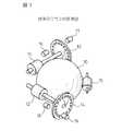
図1は従来のマウスの原理図であって、ユーザによるマウスの操作によってボール10が回転する。このボール10に対して相互に直交するX軸およびY軸に沿って、X軸ローラ11およびY軸ローラ12がボール10に接触するように配置されている。
X軸ローラ11およびY軸ローラ12の先端には一定角度ごとにスリットの設けられたX軸スリット円盤13およびY軸スリット円盤14が取り付けられており、ボール10の回転に応じて、これらスリット円盤13および14も回転する。
【0004】
なお、ボール10とX軸ローラ11およびY軸ローラ12との接触を維持するために、X軸およびY軸に対して45度の方向に押さえローラ15が設置されている。
そして、X軸スリット円盤13の両側にX軸発光素子16とX軸受光素子17が、Y軸スリット円盤14の両側にY軸発光素子18とY軸受光素子19が、設置されている。
【0005】
図2は従来のマウスの4面図であって、ロアケース21とアッパーケース22とを嵌合させた後、アッパーケース22の前方にクリックスイッチが組み込まれたキートップ23を差し込みアッパーケース22に嵌合させる構造となっている。
図3は従来のマウスの構成図であって、X軸受光素子17およびY軸受光素子19、ならびにキートップ23に設置されている右クリックスイッチ231および左クリックスイッチ232は、それぞれマウスに内蔵される制御部31に接続されている。マイクロプロセッサで構成される制御部31はX軸受光素子17およびY軸受光素子19から出力されるパルスの計数値ならびに右クリックスイッチ231および左クリックスイッチ232の操作を所定のフォーマットのデータとしてPCに伝送する。
【0006】
即ち、マウスに移動量をX軸およびY軸方向に分解して検出し、この検出結果に応じてディスプレイ上に表示されているカーソルを移動させ、カーソルがアイコン上に重なったときにクリックスイッチを操作して、アイコンに対応する動作を行わせる。
【0007】
【発明が解決しようとする課題】
しかしながら、ディスプレイ画面に表示されている画像を上下あるいは左右に移動させるいわゆるスクロール操作を行う場合には改めてカーソルをスクロールバーに移動させた後クリックスイッチを操作すること、あるいはマウスを繰り返し上下に移動させることが必要となり、上記の操作が煩雑となること避けることができない。
【0008】
本発明は上記課題に鑑みなされたものであって、クリックスイッチの間に、あるいはクリックスイッチに代えて小型のタッチパネルを設置してマウスの機能を向上させることにより、操作を簡略化することの可能なマウスを提供することを目的とする。
【0009】
【課題を解決するための手段】
第1の発明に係るマウスは、マウスの移動量を検出する移動量検出手段と、クリックスイッチの操作状態を検出するクリックスイッチ操作状態検出手段と、マウスを把持する手の指の接触面への接触状態を検出する指接触状態検出手段と、移動量検出手段で検出されたマウスの移動量、クリックスイッチ操作状態検出手段で検出されたクリックスイッチの操作状態および指接触状態検出手段で検出された指の移動量をコンピュータに対する1組の操作指令として送信する送信手段と、を具備する。
【0010】
第1の発明に係るマウスにあっては、マウスを移動させる、もしくはクリックスイッチを操作する以外に指を移動させることによってコンピュータに対する操作指令が出力される。
第2の発明に係るマウスは、指接触状態検出手段が、指の接触時間を測定する接触時間測定手段と、接触時間測定手段で計測された指の接触時間に応じてコンピュータに2以上の異なる操作指令を発生する操作指令発生手段と、を具備する。
【0011】
第2の発明に係るマウスにあっては、指移動量検出手段への指の接触時間に応じてコンピュータに異なる操作指令が出力される。
第3の発明に係るマウスは、操作指令発生手段が、接触時間測定手段で計測された指の接触時間が予め定められた閾値以下であるときはタッピング操作が行われたものと認識する。
【0012】
第3の発明に係るマウスにあっては、指移動量検出手段への指の接触時間が閾値より短時間であるときはタッピング操作が行われたものとしてタッピング操作に対応する操作指令が出力される。
第4の発明に係るマウスは、操作指令発生手段が、接触時間測定手段で計測された指の接触時間が予め定められた閾値以上であるときは指の移動量に応じてコンピュータに2以上の異なる操作指令が出力される。
【0013】
第4の発明に係るマウスにあっては、指移動量検出手段への指の接触時間が閾値より長時間であるときは指の移動量に応じてコンピュータに2以上の異なる指令信号が出力される。
第5の発明に係るマウスは、マウスの移動量を検出する移動量検出手段と、マウスを把持する手の指の操作面への接触状態を検出する指接触状態検出手段と、移動量検出手段で検出されたマウスの移動量および指接触状態検出手段で検出された指の接触状態をコンピュータに対する1組の操作指令として送信する送信手段と、を具備する。
【0014】
第5の発明に係るマウスにあっては、マウスを移動させる以外に指を移動させることによってコンピュータに対する操作指令が出力される。
第6の発明に係るマウスは、マウスの移動量を検出する移動量検出手段と、マウスを把持する手の指の操作面に対する接触状態を操作面を分割した複数の領域毎に検出する領域毎指接触状態検出手段と、移動量検出手段で検出されたマウスの移動量および領域毎指接触状態検出手段で検出された領域毎の指の接触状態をコンピュータに対する1組の操作指令として送信する第2の送信手段と、を具備する。
【0015】
第6の発明に係るマウスにあっては、マウスを移動させる以外に複数の領域で指を移動させることによってコンピュータに対する操作指令が出力される。
第7の発明に係るマウスは、操作面を複数の領域へ分割する分割手段と、分割手段により分割された領域に関する情報を記憶する領域情報記憶手段と、をさらに具備する。
【0016】
第7の発明に係るマウスにあっては、操作面を適宜に複数の複数の領域に分割し、領域毎に異なる操作指令が出力される。
第8の発明に係るマウスは、領域情報記憶手段が、領域に関する情報としてその領域がスイッチとして機能するスイッチ領域であるか指の移動量を検出するために機能する移動量検出領域であるかを示す領域機能情報を記憶する。
【0017】
第8の発明に係るマウスにあっては、領域はスイッチとして、または指の移動量の検出のために使用される。
第9の発明に係るマウスは、指接触状態検出手段が、マウスの後方上部を覆うアッパーケースと一体に形成された支持部上に搭載され、その周囲がマウスの前方上部を覆うキートップに設けられた窓の窓枠によってマウス本体に固定される構造である。
【0018】
第9の発明に係るマウスにあっては、指移動量検出手段はアッパーケースと一体に形成さられた支持部とキートップに設けられた窓の窓枠とによって固定される。
第10の発明に係るマウスは、支持部前方のアッパーケースおよび前記キートップに相互に嵌合する凸部・凹部を設け、組立後に凸部と凹部が嵌合して指接触状態検出手段を前記支持部上に固定する構造を有する。
【0019】
第10の発明に係るマウスにあっては、キートップとアッパーケースを組み合せると指接触状態検出手段が支持部上に固定される。
第11の発明に係るマウスは、指接触状態検出手段が、受け板上に搭載され、その周囲がマウスの後方上部を覆うアッパーケース内に挿入される板バネの前端部に設けられた窓枠によって固定される構造を有する。
【0020】
第11の発明に係るマウスにあっては、指接触状態検出手段が独立の部品として構成される。
第12の発明に係るマウスは、受け板の前端部および窓枠の前端部に相互に嵌合する凸部・凹部を設け、組立後に凸部と凹部が嵌合して指接触状態検出手段を受け板上に固定する構造を有する。
【0021】
第12の発明に係るマウスにあっては、受け板と枠とを組み合せると指接触状態検出手段が受け板上に固定される。
第13の発明に係るマウスは、支持部上面または受け板上面に所定間隔毎に溝が形成される。
第13の発明に係るマウスにあっては、支持部または受け板に埃の付着を防止する溝が形成される。
【0022】
第14の発明に係るマウスは、窓枠の少なくとも1辺に所定間隔ごとに突起を設ける。
第14の発明に係るマウスにあっては、指で突起に接触することによりブラインドで指の移動量が検知される。
第15の発明に係るマウスは、窓枠の対向する2辺のそれぞれに異なる間隔ごとに突起を設ける。
【0023】
第15の発明に係るマウスにあっては、ブラインドで2種類の移動量が検知される。
第16の発明に係るマウスは、指接触状態検出手段の接触面上面に所定間隔ごとに突起を形成する。
第16の発明に係るマウスにあっては、指で突起に接触することによりブラインドで指の移動量が検知される。
【0024】
第17の発明に係るマウスは、指接触状態検出手段の予め定められた点を押下したときに出力される情報に基づいてその後の押下位置座標を補正する補正係数を算出する補正係数算出部をさらに具備する。
第17の発明に係るマウスにあっては、補正係数を使用することにより指接触状態検出手段の設置に起因する押下位置検出誤差が補正される。
【0025】
【発明の実施の形態】
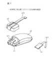
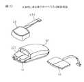
図4は本発明に係る第1のマウス40の斜視図、図5は第1のマウスの4面図であって、ロアケース41の後方部分はアッパーケース42によっておおわれている。またロアケース41の前方部分は、左右にクリックスイッチ操作部が形成されたキートップ43によっておおわれている。
【0026】
キートップ43の中央部分には窓が形成されており、内側にはタッチパネル44が嵌め込まれている。なお、マウス40の操作信号はケーブル45を介してPCに伝送される。
図6は第1のマウス40の側断面図、図7は第1のマウス40の分解斜視図であって、ロアケース41には図1に示したボール10、Y軸ローラ12、Y軸スリット円盤14および回路基板60が搭載されている。なお、X軸ローラ11ならびにX軸スリット円盤13もロアケース41に搭載されるが、図6には示されていない。
【0027】
なお、ロアケース41に嵌合されるアッパーケース42の前方中央部にはタッチパネル44を支持するための支持部421が形成されている。なお、タッチパネル44には先端にインサートが設けられたフラットケーブル440が接続されており、タッチパネル44を支持部421上に搭載した後に、フラットケーブル440のインサートを回路基板60に設けられたレセプタクル(図示せず)に差し込むことによってタッチパネル44と回路基板60とが電気的に接続される。
【0028】
キートップ43には板バネ431が設けられており、タッチパネル44を支持部411上に搭載した後に、板バネ431をアッパーケース42に差し込みながらキートップ43をアッパーケース42と嵌合させると、タッチパネル44はキートップ43中央部に形成された窓の窓枠によってマウス40に固定される。
図6にはアッパーケース42とキートップ43の嵌合状態を示す拡大図も示しているが、アッパーケース42の嵌合部には楔状の凸部、キートップ43にはこの凸部と嵌合する凹部を設ける。
【0029】
そして、キートップ43をアッパーケース42の上方から滑り込ませると、キートップ43の嵌合部はキートップ自体の弾性により変形してアッパーケース42の凸部を乗り越え、キートップ43の凹部とアッパーケース42の凸部が嵌合すると変形は解除され、嵌合は強固となる。
図8はタッチパネル44の他の実装方法の説明図、図9はこの方法を採用したときのタッチパネルアセンブリの組立工程の説明図である。
【0030】
即ち、板バネ431の先端には受け板432が取り付けられており、タッチパネル44を受け板432上に搭載し、その上から枠433で覆う。
図9は枠433の取り付け工程を示しており、まずタッチパネル44が搭載された受け板432の後端を枠433の後端に嵌合し、次に受け板432の先端を枠433の前端に嵌合する。
【0031】
図9の拡大図に示すように枠433の前端下面には楔状の瓜が形成されており、枠433と受け板432はタッチパネル44をはさんで強固に一体化される。図10は受け板の斜視図であって、受け板432の上面には適当なピッチで溝が形成されている。
この溝を形成することにより、タッチパネル44に埃が付着することを防止することが可能となる。
【0032】
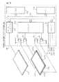
図11は本発明に係るマウス40に搭載されるタッチパネル44の断面図であって、柔軟性を有する膜441とその下面一面に塗布された抵抗膜442で構成される上側膜443と、基板444とその上面一面に塗布された抵抗膜445で構成される下側膜446とを有する。
上側膜443と下側膜446とは操作領域においては空隙を隔てて対向配置され、周辺部においては絶縁材447によって支持されている。なお、絶縁材447の上部には上側膜443下面の抵抗膜442と電気的に接触する上側電極448aおよび448bが、下部には下側膜446上面の抵抗膜445と電気的に接触する下側電極449aおよび449bが設置されている。
【0033】
図12はタッチパネル44の押下位置検出原理図であって、上側膜443上の1点Pが押下された場合を示す。即ち上側膜443上の1点Pが押下されると、上側膜443下面に塗布された抵抗膜442は、点P’において下側膜446上面の抵抗膜445と接触する。
一方の下側電極449aは直流電源VCCに接続され、他方の下側電極449bは接地されている。そして一方の上側電極448aおよびbは、A/Dコンバータ90に接続されている。
【0034】
ここで2つの下側電極449aおよび449bの間の距離をX、接地された下側電極449bと点P’との間の距離をxとすると、A/Dコンバータ90で測定される電圧VXは次式に示すように押下位置と接地された下側電極449bとの間の距離に比例した電圧となる。
VX=(x/X)・Vcc
同様にY方向の押下位置における電圧VYも次式により検出できる。
【0035】
VY=(y/Y)・Vcc
ただしyは押下位置と接地側電極との距離、Yは2つの電極間の距離である。
従って、押下位置の座標(x,y)を次式により算出することができる。
x=(VX/Vcc)・X
y=(VY/Vcc)・Y
図13は第1のマウスの構成図であって、マイクロコンピュータシステムである制御部100はバス101に、CPU102、メモリ103、入力インターフェイス104、出力インターフェイス105およびA/Dコンバータ90が接続されて構成される。
【0036】
入力インターフェイス104には従来のマウスと同じくX軸受光素子17、Y軸受光素子19、右クリック231および左クリック232が接続される。また、A/Dコンバータ90には上側膜443が上側電極448a、448bを介して接続されている。
出力インターフェイス105には4つのスイッチング素子Q1〜Q4のベースが接続されている。第1のトランジスタQ1および第2のトランジスタQ2のコレクタは直流電源VCCに接続されており、第1のトランジスタQ1のエミッタは下側電極449aに、第2のトランジスタQ2のエミッタは下側電極449cに接続されている。
【0037】
第3のトランジスタQ3および第4のトランジスタQ4のエミッタは接地されており、第3のトランジスタQ3のコレクタは下側電極449bに、第4のトランジスタQ4のコレクタは下側電極449cに接続されている。
図14は制御部10で実行される検出ルーチンのフローチャートであって、一定時間ごとに割り込み処理として実行される。
【0038】
ステップ140において左右クリックスイッチのオン・オフ状態CSLおよびCSRを読み込む。即ち左クリックスイッチがオンであればCSLは “1" に、オフであればCSLは “0" に設定される。また右クリックスイッチがオンであればCSRは “1" に、オフであればCSRは “0" に設定される。
次にステップ141で入力インターフェイス104に内蔵されているカウンタからボール10の回転量、即ちマウスの移動量CX、CYを読み取る。
【0039】
ステップ142において第1のトランジスタQ1および第3のトランジスタQ3をオン、第2のトランジスタQ2および第4のトランジスタQ4をオフとし、ステップ143でA/Dコンバータ90を介してタッチパネル44のX方向の電圧VXを読み取る。
ステップ144において第2のトランジスタQ2および第4のトランジスタQ4をオン、第1のトランジスタQ1および第3のトランジスタQ3をオフとし、ステップ145でA/Dコンバータ90を介してタッチパネル44のY方向の電圧VYを読み取る。
【0040】
ステップ146でタッチパネル44の押下位置の座標X、Yを演算し、ステップ147で左右クリックスイッチのオン・オフ状態CSLおよびCSR、マウスの移動量CX、CYならびにタッチパネル44の押下位置の座標X、YをPCに転送してこのルーチンを終了する。
図15はPCに転送されるフォーマットの1例であって、8ビットで構成されるワードを5ワード使用する。
【0041】
即ち第1ワードは4ビットづつ2つに区分され、先頭の4ビットに左クリックスイッチの状態CSLが、後方の4ビットに右クリックスイッチの状態CSRが格納される。
第2ワードにはX方向のマウスの移動量CXが、第3ワードにはY方向のマウスの移動量CYが格納される。そして第4ワードには押下位置の座標Xが、第5ワードには押下位置の座標Yが格納される。これら5ワードは一定時間ごとにシリアルデータとして順次PCに転送される。
【0042】
図16は制御部100で実行されるタッチパネル処理ルーチンのフローチャートであって、ステップ160においてタッチパネル44の状態、即ちタッチパネル44が指によって押下されているかを読み込み、ステップ161で指による押下が有るかを判定する。
ステップ161で肯定判定されたとき、即ちタッチパネル44が指によって押下されているときはステップ162でタイマを起動してステップ160に戻る。
【0043】
ステップ161で否定判定されたとき、即ちタッチパネル44が指によって押下されていないときはステップ163でタイマをオフとする。
ステップ164でタイマの計数値が第1の閾値T1以下であるかを判定するが、肯定判定されたとき、即ちタイマの計数値が第1の閾値T1以下であるときは直接ステップ165においてタイマをリセットしてステップ160に戻る。
【0044】
ステップ164で否定判定されたとき、即ちタイマの計数値が第1の閾値T1以上であるときはステップ166においてタイマの計数値が第2の閾値T2以下であるかを判定する。
ステップ166において肯定判定されたとき、即ちタイマの計数値が第2の閾値T2以下であるときは、ステップ137で例えば左クリックスイッチが操作されたものとしてCSLを “1" に設定してステップ165に進む。
【0045】
ステップ166において否定判定されたとき、即ちタイマの計数値が第2の閾値T2以上であるときはステップ168で指移動処理を行った後ステップ165に進む。
図17はタッチパネルのタイミング図であって、(イ)のようにタッチパネルへの接触時間が第1の閾値T1以下であるときは誤って操作されたものとしてこの操作を無視する。(ロ)のようにタッチパネルへの接触時間が第1の閾値T1以上第2の閾値T2以下であるときはタッピング操作として、例えば左クリックスイッチが操作されたものとみなす。さらに、(ハ)のように操作パネルへの接触時間が第2の閾値T2以上であるときには指によって、例えばスクロール指令が出力されたものとみなす。
【0046】
図18はスクロール指令出力の説明図であって、X方向の操作のみを説明する。点X0は前回PCに転送された押下位置の座標がXであり、今回の押下位置の座標がX1またはX2である場合について考える。
L1=X1−X0<LX
L2=X2−X0>LX
とすると、PC内に組み込まれているソフトウエアにおいて、今回の押下位置の座標が少ない場合はタッチパネルから操作指令は出力されていなものと判断し、覆い場合はタッチパネルから操作指令が出力されているものとして、所定の動作、例えばスクロールを実行する。
【0047】
図19はタッチパネル処理ルーチンのステップ168で実行される指移動処理ルーチンのフローチャートであって、ステップ1680で今回の押下位置の座標Xを読み込み、ステップ1681で前回転送された押下位置の座標X0との差Lを算出する。
ステップ1682で差Lが予め定められた閾値LXより大であるかを判定し、肯定判定されたときはステップ1683でスクロール動作を行った後に、否定判定されたときは直ちにステップ1684に進む。
【0048】
そして、ステップ1684で今回の押下位置の座標Xを前回の押下位置の座標X0としてこのルーチンを終了する。
上記第1のマウスにおいては2つのクリックスイッチの間にタッチパネルを設置しているが、第2のマウスはクリックスイッチを省略しキートップ全面にタッチパネルを設置し、タッチパネルを複数の領域に分割して使用する。
【0049】
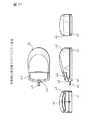
図20は本発明に係る第2のマウスの斜視図、図21は第2のマウスの4面図であって、キートップ43の上面全体に窓が形成されており、内側にタッチパネル44が嵌め込まれる。なお、マウス40の操作信号はケーブル45を介してPCに伝送される。
図22は本発明に係る第2のマウスの分解斜視図であって、第1のマウスと同様にアッパーケース42の前面中央部全体に設けられた支持部421にタッチパネル44が搭載され、その上からキートップ43で覆うことによりタッチパネル44がマウスに固定される。
【0050】
図23は本発明に係る第2のマウスの構成図であって、入力インターフェイス104にはX軸受光素子17およびY軸受光素子19だけが接続される点、および例えばフラッシュメモリであるタッチパネル設定メモリ106が設置される点が第1のマウスの構成と相違する。
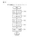
図24はPCで実行されるタッチパネル設定ルーチンのフローチャートであって、ステップ240で領域番号を表すインデックス “i" を “1" に設定する。
【0051】
ステップ241で領域 “i" の左上の座標{Xu(i),Yu(i)}を、ステップ242で領域 “i" の右下の座標{XL(i),YL(i)}を読み込み、続いてステップ243で必要に応じてマウスに設置されたタッチパネル上の操作とPC上の操作とを関連付ける補正係数C(i)を設定する。
そしてステップ244で領域 “i" についての設定データを所定のフォーマット化した後、ステップ245で設定終了かを判定する。
【0052】
ステップ245で否定判定されたとき、即ちタッチパネルの設定が終了でないときはステップ246でインデックスiをインクリメントしてステップ241に戻る。
ステップ245で肯定判定されたとき、即ちタッチパネルの設定が終了したときはステップ247でフォーマットの最後にターミネータを書き込んでこのルーチンを終了する。
【0053】
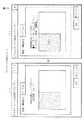
図25は本ルーチンで使用されるGUIの1例であって、(イ)は領域設定方法を、(ロ)は機能設定方法を示す。まず、(イ)に示すように領域を定義するためにディスプレイ上に表示されるカーソルを左上から右下にドラッグし、所定位置で確定することにより領域が決定される。次に、(ロ)に示すように領域の性質(スイッチとして使用するか、連続操作用にしようするかの区別、および、連続操作用に使用する場合は分解能の設定)を行う。
【0054】
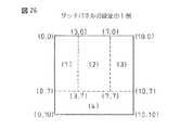
図26はタッチパネルの設定の1例であって、タッチパネルを4領域に分割し、領域(1)を左クリックスイッチとして、領域(2)を上下方向のスクロール制御領域として、領域(3)を右クリックスイッチとして、そして領域(4)を左右方向スクロール制御領域として使用する場合を示す。
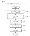
図27は図26に示すようにタッチパネルを分割した場合のタッチパネル設定データのフォーマットであって、最初に1ワードのスタータが、次に領域1から4の設定データが、最後に1ワードのターミネータが配置される。各領域の設定データはそれぞれが1ワードである左上X座標、左上Y座標、右下X座標、右下Y座標、領域番号、および補正係数C(i)の合計6ワードから構成される。なお、補正係数C(i)は “0" が設定されたときはその領域がオンオフスイッチとして使用されることを、正数が設定されたときはゲインを表すものとする。
【0055】
図27中に記載されているデータはタッチパネルが縦横それぞれ10要素で構成されているとした場合を示す。このデータはPCから第2のマウスの制御部100に含まれるタッチパネル設定メモリ106に転送される。
なお、工場出荷時にいわゆるデフォルトを設定する場合には、直接タッチパネル設定メモリ106にデータを書き込んでもよい。
図28は本発明に係る第2のマウスの使用中に制御部100で実行されるマウス処理ルーチンのフローチャートであって、ステップ280で入力インターフェイス104に内蔵されるカウンタのカウント値CXおよびCYを読み込む。
【0056】
次にステップ281でタッチパネルの押下位置を検出し、ステップ282で操作処理を実行するが、それぞれの詳細は後述する。
ステップ283でマウスの操作データをフォーマット化し、ステップ284でフォーマット化されたデータをPCに送出してこのルーチンを終了する。
図29はマウス処理ルーチンのステップ281で実行される押下位置検出ルーチンのフローチャートであって、ステップ290において第1のトランジスタQ1および第3のトランジスタQ3をオン、第2のトランジスタQ2および第4のトランジスタQ4をオフとし、ステップ291でA/Dコンバータ90を介してタッチパネル44のX方向の電圧VXを読み取る。
【0057】
ステップ292において第2のトランジスタQ2および第4のトランジスタQ4をオン、第1のトランジスタQ1および第3のトランジスタQ3をオフとし、ステップ293でA/Dコンバータ90を介してタッチパネル44のY方向の電圧VYを読み取る。最後に、ステップ294でタッチパネル44の押下位置の座標X、Yを演算してこのルーチンを終了する。
【0058】
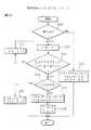
図30はマウス処理ルーチンのステップ282で実行される操作処理ルーチンのフローチャートであって、ステップ300で押下位置検出ルーチンで押下が検出されたかを判定する。
ステップ300で否定判定されたとき、即ち押下が検出されなかったときは、ステップ301で次式の基づき領域1からimax(本実施例においては4)について、本ルーチンの出力ΔX(i)およびΔY(i)をリセットして、このルーチンを終了する。
【0059】
ΔX(i)← 0.0
ΔY(i)← 0.0
ステップ300で肯定判定されたとき、即ち押下が検出されたときには、ステップ302で領域番号を表すインデックスiを “1" に設定する。
ステップ303で押下位置が領域iにあるかを次式により判定する。
【0060】
XU(i)≦X≦XL(i) かつ YU(i)≦Y≦YL(i)
ステップ303で否定判定されたとき、即ち、押下位置が領域iにないときはステップ304でインデックスiをインクリメントしてステップ302に戻る。
ステップ303で肯定判定されたとき、即ち、押下位置が領域iにあるときはステップ305で補正係数C(i)が “0.0" であるかを判定する。
【0061】
ステップ305で肯定判定されたとき、即ち、補正係数C(i)が “0.0" であるときは、領域iがスイッチとして使用されているものとして、ステップ306でスイッチがオンとなっていることを表すために本ルーチンの出力ΔX(i)およびΔY(i)を “1.0" にセットして、このルーチンを終了する。
ステップ305で否定判定されたとき、即ち、補正係数C(i)が “1.0" であるときは、領域iがカーソル操作のために使用されているものとして、ステップ307で次式により本ルーチンの出力ΔX(i)およびΔY(i)を算出する。
【0062】
ΔX(i)← C(i)・(X−X’)
ΔY(i)← C(i)・(Y−Y’)
ただし(X’,Y’)は前回検出された押下位置の座標である。
そして、ステップ308で前回の押下位置を次式に更新してこのルーチンを終了する。
【0063】
X’← X
Y’← Y
図31はマウス操作データのフォーマットであって、スタータの次にボールの回転量(CX,CY)が、続いて4つの領域の出力ΔX(i)とΔY(i)、ならびに領域番号iが収納され、マウスからPCに送出される。
【0064】
なお、第1および第2のマウスにおいては、直接目視することなく、ブラインドで操作する場合が多いためタッチパネル上での指の移動量を指先で感知できるとが望ましい。
図32はタッチパネルの上面図(その1)であって、タッチパネル44を固定するキートップ43の窓枠に複数の突起431を設け、指先に接触する突起431の数によってブラインドで指の移動量を知ることが可能となる。
【0065】
図33はタッチパネルの上面図(その2)であって、窓枠の相対する2辺にピッチの異なる突起431および432を設け、2段階の移動量をブラインドで知ることが可能となる。
図34はタッチパネルの上面図(その3)であって、柔軟性を有する膜441の上面に複数の凹部あるいは凸部を形成してもよい。
【0066】
上記本発明に係るマウスに示すようにタッチパネルを搭載した場合には、押下位置を正確に検出することが必要となる。
しかし、タッチパネルにおいては、電極パターンに印刷誤差、電極パターンの抵抗のバラツキ、電気的接触部の接触抵抗のバラツキ、さらにはタッチパネル抵抗膜の不均一性に起因して押下位置の検出精度が悪化して、スクロール速度が変動するおそれがある。
【0067】
この変動を抑制するためには、タッチパネルに印加される電圧VCCを制御部100で監視し、ソフトウエア的に電圧変動を補正することも可能である。
しかし、上記方法を実現するためには接続回路、A/Dコンバータ等を追加する必要があり、マウスに搭載される制御部100で実現することは困難である。そこで、マウス内に取り付け誤差補正部を組み込むことが望ましい。
【0068】
図35はマウス工場出荷時に実行される補正係数算出ルーチンのフローチャートであって、本発明に係るマウスと補正係数決定装置として機能するPCとを接続した状態でPCにおいて実行される。
ステップ350でタッチパネルの上端を押下したときに検出される上端押下点検出値JX0を検出する。
【0069】
ついで、ステップ351でタッチパネルの下端を押下したときに検出される下端押下点検出値JX1を検出する。
ステップ352でタッチパネルの上端を押下したときの理論値である上端押下点理論値HX0およびタッチパネルの下端を押下したときの理論値である下端押下点理論値HX1を読み出す。
【0070】
理論値と検出値の間には1次関数の関係が成立するので次式が成立する。
a・JX0+b=HX0
a・JX1+b=HX1
従って、補正係数a、bはステップ353において次式により算出することができる。
【0071】
a ← (HX0−HX1)/(JX0−JX1)
b ← HX0−JX0・(HX0−HX1)/(JX0−JX1)
ステップ354で補正係数a、bをタッチパネル設定メモリ106に書き出してこのルーチンを終了する。
図36は押下点説明図であって、上端押下点および下端押下点はタッチパネルの窓枠の上端および下端とすることが一般的である。
【0072】
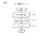
図37は、補正係数a、bをマウス内の制御部100で実行される押下位置補正ルーチンのフローチャートであって、ステップ370でタッチパネルの押下点の座標Xを検出する。
次に、ステップ371でタッチパネル設定メモリ106から補正係数a、bを読み出し、補正座標Xoutを次式により算出する。
【0073】
Xout← a・X+b
ステップ372で補正座標XoutをPCに出力してこのルーチンを終了する。なお、補正係数算出ルーチンで算出された補正係数をPC内の不揮発メモリ(例えばハードディスク)に書き出し、押下位置補正ルーチンをPCで実行することによりマウスから伝送される押下位置を補正するようにしてもよい。
【0074】
また、上記実施例ではタッチパネルの押下位置を1次元的に検出しているが、押下位置を2次元的に検出する場合にも取り付け誤差補正部を組み込むことも可能であることは明らかである。
さらに、タッチパネルを複数の領域に分割し、各領域毎に異なる補正係数を使用することも可能である。例えば、タッチパネルを左右に2分割し、上端から下端までを左側領域で200分解能に、右側領域で400分解能に設定することもできる。この場合は、同じ長さの押下位置の移動に対して右側領域を操作したときのスクロール速度は左側領域を操作したときにスクロール速度の倍となる。
【0075】
以上実施例においては、ボールの回転量によってマウスの移動量を検出するマウスについて説明したが、マウスを移動させる基板上に所定ピッチで格子を描いて横断した格子の数をカウントする光学式マウスに対しても本発明を適用することは明らかである。
【0076】
【発明の効果】
第1の発明に係るマウスによれば、マウスを移動させる、もしくはクリックスイッチを操作する以外に指を移動することによってコンピュータに対する操作指令を出力することが可能となる。
第2の発明に係るマウスによれば、指接触状態検出手段への指の接触時間に応じてコンピュータに異なる操作指令を出力することが可能となる。
【0077】
第3の発明に係るマウスによれば、指接触状態検出手段への指の接触時間が閾値より短時間であるときはタッピング操作が行われたものとしてタッピング操作に対応する操作指令を出力することが可能である。
第4の発明に係るマウスによれば、指接触状態検出手段への指の接触時間が閾値より長時間であるときに指の移動量に応じてコンピュータに2以上の異なる指令信号を出力することが可能となる。
【0078】
第5および第6の発明に係るマウスによれば、クリックスイッチを省略して指接触状態検出手段だけを搭載することにマウスの構成を簡略化することができる。
第7の発明に係るマウスによれば、指接触状態検出手段を複数の領域に分割することにより複数の操作指令を出力することが可能となる。
【0079】
第8の発明に係るマウスによれば、領域をスイッチとして、あるいは領域を指の移動量の検出の検出のために使用することが可能となる。
第9の発明に係るマウスによれば、指接触状態検出手段をアッパーケースと一体に形成さられた支持部とキートップに設けられた窓の窓枠とで固定することにより組み立て工程を簡易化することが可能となる。
【0080】
第10の発明に係るマウスによれば、キートップとアッパーケースを組み合せると指接触状態検出手段が支持部上に固定されるので組立工程を簡略化することが可能となる。
第11の発明に係るマウスによれば、指接触状態検出手段が独立したアセンブリに取り付けられるので、アッパーケースの形状を自由に設計することが可能となる。
【0081】
第12の発明に係るマウスによれば、受け板を枠に嵌合させると指接触状態検出手段が固定されるので、組立工程を簡略化することが可能となる。
第13の発明に係るマウスによれば、指接触状態検出手段の表面に付着する埃を低減することが可能となる。
第14の発明に係るマウスによれば、指で突起に接触することによりブラインドで指の移動量を検知することが可能となる。
【0082】
第15の発明に係るマウスによれば、ブラインドで2種類の移動量を検知することが可能となる。
第16の発明に係るマウスにあっては、指で突起に接触することによりブラインドで指の移動量を検知することが可能となる。
第17の発明に係るマウスによれば、押下位置を補正係数により補正することにより指接触状態検出手段の取り付けに起因する誤差を補正することが可能となる。
【図面の簡単な説明】
【図1】従来のマウスの原理図である。
【図2】従来のマウスの4面図である。
【図3】従来のマウスの構成図である。
【図4】本発明に係る第1のマウスの斜視図である。
【図5】本発明に係る第1のマウスの4面図である。
【図6】本発明に係る第1のマウスの側断面図である。
【図7】本発明に係る第1のマウスの分解斜視図である。
【図8】タッチパネルの他の実装方法の説明図である。
【図9】タッチパネルアセンブリの組立工程の説明図である。
【図10】溝を形成した受け板の斜視図である。
【図11】タッチパネルの断面図である。
【図12】タッチパネルの押下位置検出原理図である。
【図13】本発明に係る第1のマウスの構成図である。
【図14】検出ルーチンのフローチャートである。
【図15】転送フォーマットである。
【図16】タッチパネル処理ルーチンのフローチャートである。
【図17】タッチパネルのタイミング図である。
【図18】スクロール指令出力の説明図である。
【図19】指移動処理ルーチンのフローチャートである。
【図20】本発明に係る第2のマウスの斜視図である。
【図21】本発明に係る第2のマウスの4面図である。
【図22】本発明に係る第2のマウスの分解斜視図である。
【図23】本発明に係る第2のマウスの構成図である。
【図24】タッチパネル設定ルーチンのフローチャートである。
【図25】タッチパネル設定GUIである。
【図26】タッチパネルの設定の1例である。
【図27】タッチパネル設定データのフォーマットである。
【図28】マウス処理ルーチンのフローチャートである。
【図29】押下位置検出ルーチンのフローチャートである。
【図30】操作処理ルーチンのフローチャートである。
【図31】マウス操作データのフォーマットである。
【図32】タッチパネルの上面図(その1)である。
【図33】タッチパネルの上面図(その2)である。
【図34】タッチパネルの上面図(その3)である。
【図35】補正係数算出ルーチンのフローチャートである。
【図36】押下位置説明図である。
【図37】押下位置補正ルーチンのフローチャートである。
【符号の説明】
40…マウス
41…ロアーケース
42…アッパーケース
43…キートップ
44…タッチパネル[0001]
BACKGROUND OF THE INVENTION
The present invention relates to a mouse used as a pointing device for a personal computer (PC), and more particularly to a mouse with improved functions.
[0002]
[Prior art]
In recent years, a GUI (Graphical User Interface) has been adopted to improve the operability of the PC, but a mouse is often used as a pointing device for instructing an icon or the like on a display screen.
Most of the mice that are generally used at present are of the type that outputs the amount of operation in the X-axis and Y-axis directions by the user and the operation of the two click switches.
[0003]
FIG. 1 is a principle diagram of a conventional mouse, and a
An
[0004]
In order to maintain contact between the
An X-axis
[0005]
FIG. 2 is a four-sided view of a conventional mouse. After the
FIG. 3 is a configuration diagram of a conventional mouse. The X-bearing
[0006]
That is, the mouse detects the amount of movement in the X-axis and Y-axis directions, moves the cursor displayed on the display in accordance with the detection result, and sets the click switch when the cursor is over the icon. Operate and perform the action corresponding to the icon.
[0007]
[Problems to be solved by the invention]
However, when performing a so-called scroll operation for moving the image displayed on the display screen up and down or left and right, the cursor is moved to the scroll bar and then the click switch is operated, or the mouse is repeatedly moved up and down. Therefore, the above operation is complicated and cannot be avoided.
[0008]
The present invention has been made in view of the above problems, and it is possible to simplify the operation by improving the function of the mouse by installing a small touch panel between the click switches or instead of the click switches. The purpose is to provide a simple mouse.
[0009]
[Means for Solving the Problems]
A mouse according to a first aspect of the present invention is a movement amount detection means for detecting a movement amount of a mouse, a click switch operation state detection means for detecting an operation state of the click switch, and a contact surface of a finger of a hand holding the mouse. Finger contact state detection means for detecting the contact state, mouse movement amount detected by the movement amount detection means, click switch operation state detected by the click switch operation state detection means, and finger contact state detection means Transmitting means for transmitting a finger movement amount as a set of operation commands to the computer.
[0010]
In the mouse according to the first aspect of the invention, an operation command for the computer is output by moving the mouse or moving a finger in addition to operating the click switch.
In the mouse according to the second aspect of the invention, the finger contact state detecting means has two or more different computer in accordance with the contact time measuring means for measuring the finger contact time and the finger contact time measured by the contact time measuring means. Operation command generating means for generating an operation command.
[0011]
In the mouse according to the second invention, different operation commands are output to the computer in accordance with the finger contact time with the finger movement amount detection means.
The mouse according to the third aspect of the invention recognizes that the tapping operation has been performed when the operation command generation means is less than or equal to a predetermined threshold value as measured by the contact time measurement means.
[0012]
In the mouse according to the third invention, when the finger contact time with the finger movement amount detection means is shorter than the threshold, the operation command corresponding to the tapping operation is output as the tapping operation is performed. The
According to a fourth aspect of the present invention, when the operation command generating means has a finger contact time measured by the contact time measuring means equal to or greater than a predetermined threshold value, the mouse is instructed to send two or more to the computer according to the amount of finger movement. Different operation commands are output.
[0013]
In the mouse according to the fourth aspect of the invention, when the contact time of the finger with the finger movement amount detection means is longer than the threshold, two or more different command signals are output to the computer according to the finger movement amount. The
According to a fifth aspect of the present invention, there is provided a movement amount detection means for detecting a movement amount of a mouse, a finger contact state detection means for detecting a contact state of a finger of a hand holding the mouse, and a movement amount detection means. Transmitting means for transmitting the movement amount of the mouse detected in
[0014]
In the mouse according to the fifth aspect of the invention, an operation command for the computer is output by moving a finger in addition to moving the mouse.
According to a sixth aspect of the present invention, there is provided a movement amount detecting means for detecting a movement amount of the mouse, and a region for detecting a contact state of a finger of a hand holding the mouse with respect to the operation surface for each of a plurality of regions obtained by dividing the operation surface. A finger contact state detection means, a movement amount of the mouse detected by the movement amount detection means, and a finger contact state for each area detected by the finger contact state detection means for each area are transmitted as a set of operation commands to the computer. 2 transmission means.
[0015]
In the mouse according to the sixth aspect of the invention, an operation command for the computer is output by moving a finger in a plurality of areas in addition to moving the mouse.
The mouse according to a seventh aspect of the present invention further includes a dividing unit that divides the operation surface into a plurality of regions, and a region information storage unit that stores information related to the region divided by the dividing unit.
[0016]
In the mouse according to the seventh aspect, the operation surface is appropriately divided into a plurality of regions, and different operation commands are output for each region.
In the mouse according to the eighth invention, the area information storage means determines whether the area is a switch area that functions as a switch or a movement amount detection area that functions to detect the movement amount of a finger as information related to the area. The area function information shown is stored.
[0017]
In the mouse according to the eighth aspect, the region is used as a switch or for detecting the amount of movement of the finger.
In the mouse according to the ninth aspect, the finger contact state detecting means is mounted on a support portion formed integrally with an upper case that covers the rear upper part of the mouse, and the periphery thereof is provided on a key top that covers the upper upper part of the mouse. The structure is fixed to the mouse body by the window frame of the formed window.
[0018]
In the mouse according to the ninth aspect, the finger movement amount detecting means is fixed by the support portion formed integrally with the upper case and the window frame of the window provided in the key top.
According to a tenth aspect of the present invention, there is provided a convex portion / concave portion to be fitted to the upper case in front of the support portion and the key top, and the convex portion and the concave portion are fitted to each other after the assembly to provide the finger contact state detecting means. It has a structure fixed on a support part.
[0019]
In the mouse according to the tenth aspect, when the key top and the upper case are combined, the finger contact state detecting means is fixed on the support portion.
A mouse according to an eleventh invention is a window frame provided at a front end portion of a leaf spring in which finger contact state detecting means is mounted on a receiving plate and the periphery thereof is inserted into an upper case covering the upper rear part of the mouse. It has the structure fixed by.
[0020]
In the mouse according to the eleventh aspect, the finger contact state detection means is configured as an independent component.
According to a twelfth aspect of the present invention, there is provided a convex portion / concave portion to be fitted to each other at the front end portion of the backing plate and the front end portion of the window frame. It has a structure to be fixed on the backing plate.
[0021]
In the mouse according to the twelfth invention, the finger contact state detecting means is fixed on the receiving plate when the receiving plate and the frame are combined.
In the mouse according to the thirteenth invention, grooves are formed at predetermined intervals on the upper surface of the support portion or the upper surface of the backing plate.
In the mouse according to the thirteenth invention, a groove for preventing the adhesion of dust is formed in the support portion or the receiving plate.
[0022]
The mouse according to the fourteenth aspect is provided with protrusions at predetermined intervals on at least one side of the window frame.
In the mouse according to the fourteenth aspect, the amount of movement of the finger is detected blindly by touching the protrusion with the finger.
The mouse according to the fifteenth aspect is provided with protrusions at different intervals on each of two opposing sides of the window frame.
[0023]
In the mouse according to the fifteenth aspect, two types of movement amounts are detected by the blind.
The mouse according to the sixteenth invention forms protrusions at predetermined intervals on the upper surface of the contact surface of the finger contact state detection means.
In the mouse according to the sixteenth aspect, the amount of movement of the finger is detected blindly by touching the protrusion with the finger.
[0024]
According to a seventeenth aspect of the present invention, there is provided a correction coefficient calculation unit that calculates a correction coefficient for correcting a subsequent pressed position coordinate based on information output when a predetermined point of the finger contact state detecting means is pressed. In addition.
In the mouse according to the seventeenth aspect, the pressing position detection error due to the installation of the finger contact state detecting means is corrected by using the correction coefficient.
[0025]
DETAILED DESCRIPTION OF THE INVENTION
FIG. 4 is a perspective view of the
[0026]
A window is formed in the central portion of the key top 43, and a
6 is a side sectional view of the
[0027]
A
[0028]
A
FIG. 6 also shows an enlarged view showing the fitting state of the
[0029]
Then, when the key top 43 is slid from above the
FIG. 8 is an explanatory view of another mounting method of the
[0030]
That is, a receiving
FIG. 9 shows a process of attaching the
[0031]
As shown in the enlarged view of FIG. 9, a wedge-shaped ridge is formed on the lower surface of the front end of the
By forming this groove, it is possible to prevent dust from adhering to the
[0032]
FIG. 11 is a cross-sectional view of the
The
[0033]
FIG. 12 is a view showing the principle of detecting the pressed position of the
One
[0034]
Here, when the distance between the two
VX= (X / X) · Vcc
Similarly, the voltage V at the pressed position in the Y directionYCan also be detected by the following equation.
[0035]
VY= (Y / Y) · Vcc
Where y is the distance between the pressed position and the ground side electrode, and Y is the distance between the two electrodes.
Accordingly, the coordinates (x, y) of the pressed position can be calculated by the following equation.
x = (VX/ Vcc) ・ X
y = (VY/ Vcc) ・ Y
FIG. 13 is a configuration diagram of the first mouse. The
[0036]
The
The
[0037]
Third transistor QThreeAnd the fourth transistor QFourOf the third transistor Q is grounded.ThreeOf the fourth transistor Q is connected to the lower electrode 449b.FourAre connected to the
FIG. 14 is a flowchart of a detection routine executed by the
[0038]
In
Next, in
[0039]
In
In step 144, the second transistor Q2And the fourth transistor QFourON, the first transistor Q1And the third transistor QThreeAnd the voltage V in the Y direction of the
[0040]
In
FIG. 15 shows an example of a format transferred to the PC, and uses 5 words composed of 8 bits.
[0041]
That is, the first word is divided into two 4 bit units, the left click switch state CSR is stored in the first 4 bits, and the right click switch state CSR is stored in the rear 4 bits.
The second word contains the amount of mouse movement C in the X direction.XHowever, in the third word, the amount of mouse movement C in the Y directionYIs stored. The coordinate X of the pressed position is stored in the fourth word, and the coordinate Y of the pressed position is stored in the fifth word. These 5 words are sequentially transferred to the PC as serial data at regular intervals.
[0042]
FIG. 16 is a flowchart of a touch panel processing routine executed by the
When an affirmative determination is made in
[0043]
When a negative determination is made in
In
[0044]
When a negative determination is made in
When an affirmative determination is made in
[0045]
When a negative determination is made in
FIG. 17 is a timing diagram of the touch panel. As shown in FIG.1Ignore this operation as if it was operated incorrectly if As shown in (b), the touch time on the touch panel is the first threshold T1The second threshold value T2When it is below, it is considered that, for example, the left click switch is operated as the tapping operation. Further, as shown in (c), the contact time with the operation panel is the second threshold value T.2When it is above, it is considered that a scroll command is output by a finger, for example.
[0046]
FIG. 18 is an explanatory diagram of the scroll command output, and only the operation in the X direction will be described. Point X0Is the coordinate of the pressed position previously transferred to the PC is X, and the coordinate of the pressed position this time is X1Or X2Think about the case.
L1= X1-X0<LX
L2= X2-X0> LX
Then, in the software installed in the PC, if the coordinates of the current pressed position are small, it is determined that the operation command is not output from the touch panel, and if it is covered, the operation command is output from the touch panel. As a thing, predetermined operation | movement, for example, a scroll, is performed.
[0047]
FIG. 19 is a flowchart of the finger movement processing routine executed in
In
[0048]
In
In the first mouse, a touch panel is installed between two click switches. However, in the second mouse, the click switch is omitted, the touch panel is installed on the entire key top, and the touch panel is divided into a plurality of areas. use.
[0049]
20 is a perspective view of a second mouse according to the present invention, and FIG. 21 is a four-side view of the second mouse. A window is formed on the entire top surface of the key top 43, and the
FIG. 22 is an exploded perspective view of the second mouse according to the present invention. Like the first mouse, the
[0050]
FIG. 23 is a configuration diagram of a second mouse according to the present invention, in which only the X bearing
FIG. 24 is a flowchart of a touch panel setting routine executed by the PC. In
[0051]
In
In
[0052]
If a negative determination is made in
When an affirmative determination is made at
[0053]
FIG. 25 shows an example of a GUI used in this routine. (A) shows an area setting method and (B) shows a function setting method. First, as shown in (a), in order to define a region, the cursor displayed on the display is dragged from the upper left to the lower right, and the region is determined by confirming at a predetermined position. Next, as shown in (b), the characteristics of the region (distinguishing whether to use as a switch or for continuous operation, and setting the resolution when using for continuous operation) are performed.
[0054]
FIG. 26 shows an example of touch panel settings. The touch panel is divided into four areas, area (1) is the left click switch, area (2) is the vertical scroll control area, and area (3) is the right. The case where the area (4) is used as a left / right direction scroll control area is shown as a click switch.
FIG. 27 shows the format of touch panel setting data when the touch panel is divided as shown in FIG. 26. First, the starter of one word, the setting data of
[0055]
The data described in FIG. 27 shows a case where the touch panel is composed of 10 elements vertically and horizontally. This data is transferred from the PC to the touch
Note that when setting a so-called default at the time of factory shipment, data may be directly written in the touch
FIG. 28 is a flowchart of a mouse processing routine executed by the
[0056]
Next, in
In
FIG. 29 is a flowchart of the pressed position detection routine executed in
[0057]
In
[0058]
FIG. 30 is a flowchart of the operation processing routine executed in
When a negative determination is made at
[0059]
ΔX (i) ← 0.0
ΔY (i) ← 0.0
When an affirmative determination is made in
In
[0060]
XU(I) ≦ X ≦ XL(I) and YU(I) ≦ Y ≦ YL(I)
When a negative determination is made in
When an affirmative determination is made in
[0061]
When an affirmative determination is made in
When a negative determination is made in
[0062]
ΔX (i) ← C (i) · (X−X ′)
ΔY (i) ← C (i) · (Y−Y ′)
However, (X ′, Y ′) are the coordinates of the pressed position detected last time.
In
[0063]
X ’← X
Y ’← Y
FIG. 31 shows the format of mouse operation data. The rotation amount of the ball (CX, CY), The outputs ΔX (i) and ΔY (i) of the four areas and the area number i are stored and sent from the mouse to the PC.
[0064]
In the first and second mice, it is desirable that the amount of movement of the finger on the touch panel can be detected with the fingertip because it is often operated with the blind without directly observing.
FIG. 32 is a top view (part 1) of the touch panel, in which a plurality of
[0065]
FIG. 33 is a top view (part 2) of the touch panel, in which
FIG. 34 is a top view (No. 3) of the touch panel, and a plurality of concave portions or convex portions may be formed on the top surface of the
[0066]
When the touch panel is mounted as shown in the mouse according to the present invention, it is necessary to accurately detect the pressed position.
However, in the touch panel, the detection accuracy of the pressed position deteriorates due to the printing error in the electrode pattern, the variation in the resistance of the electrode pattern, the variation in the contact resistance of the electrical contact portion, and the non-uniformity of the touch panel resistance film. The scrolling speed may fluctuate.
[0067]
In order to suppress this variation, the voltage V applied to the touch panelCCCan be monitored by the
However, in order to realize the above method, it is necessary to add a connection circuit, an A / D converter, and the like, and it is difficult to realize with the
[0068]
FIG. 35 is a flowchart of a correction coefficient calculation routine executed at the time of shipment from the mouse factory. The correction coefficient calculation routine is executed in the PC in a state where the mouse according to the present invention and the PC functioning as the correction coefficient determination device are connected.
Upper end pressing point detection value JX detected when the upper end of the touch panel is pressed in
[0069]
Next, the lower end pressing point detection value JX detected when the lower end of the touch panel is pressed in step 351.1Is detected.
The upper limit pressing point theoretical value HX, which is the theoretical value when the upper end of the touch panel is pressed in
[0070]
Since a linear function relationship is established between the theoretical value and the detected value, the following equation is established.
a ・ JX0+ B = HX0
a ・ JX1+ B = HX1
Therefore, the correction coefficients a and b can be calculated by the following equation in
[0071]
a ← (HX0-HX1) / (JX0-JX1)
b ← HX0-JX0・ (HX0-HX1) / (JX0-JX1)
In
FIG. 36 is an explanatory diagram of pressing points, and the upper pressing point and the lower pressing point are generally the upper and lower edges of the window frame of the touch panel.
[0072]
FIG. 37 is a flowchart of the pressing position correction routine executed by the
Next, in
[0073]
Xout← a ・ X + b
In
[0074]
In the above-described embodiment, the pressed position of the touch panel is detected one-dimensionally. However, it is obvious that an attachment error correction unit can be incorporated even when the pressed position is detected two-dimensionally.
Furthermore, it is also possible to divide the touch panel into a plurality of areas and use different correction coefficients for each area. For example, the touch panel can be divided into left and right, and the resolution from the upper end to the lower end can be set to 200 resolution in the left area and 400 resolution in the right area. In this case, the scroll speed when the right area is operated with respect to the movement of the pressed position of the same length is twice the scroll speed when the left area is operated.
[0075]
In the embodiments described above, the mouse that detects the amount of movement of the mouse based on the amount of rotation of the ball has been described. However, an optical mouse that counts the number of grids crossed by drawing a grid at a predetermined pitch on the substrate on which the mouse is moved is described. It is clear that the present invention applies to this case.
[0076]
【The invention's effect】
According to the mouse according to the first aspect of the present invention, it is possible to output an operation command to the computer by moving the mouse or moving a finger in addition to operating the click switch.
According to the mouse according to the second aspect of the invention, it is possible to output different operation commands to the computer according to the contact time of the finger with the finger contact state detection means.
[0077]
According to the mouse of the third invention, when the finger contact time to the finger contact state detection means is shorter than the threshold, the operation command corresponding to the tapping operation is output as the tapping operation is performed. Is possible.
According to the mouse of the fourth invention, when the finger contact time to the finger contact state detection means is longer than the threshold, two or more different command signals are output to the computer according to the amount of finger movement. Is possible.
[0078]
With the mouse according to the fifth and sixth inventions, the configuration of the mouse can be simplified by omitting the click switch and mounting only the finger contact state detecting means.
According to the mouse of the seventh invention, it is possible to output a plurality of operation commands by dividing the finger contact state detection means into a plurality of regions.
[0079]
According to the mouse according to the eighth aspect of the present invention, the area can be used as a switch or the area can be used for detection of finger movement detection.
According to the mouse according to the ninth aspect of the invention, the finger contact state detection means is fixed by the support portion formed integrally with the upper case and the window frame of the window provided on the key top, thereby simplifying the assembly process. It becomes possible to do.
[0080]
According to the mouse of the tenth invention, when the key top and the upper case are combined, the finger contact state detection means is fixed on the support portion, so that the assembly process can be simplified.
According to the mouse of the eleventh aspect, since the finger contact state detection means is attached to the independent assembly, the shape of the upper case can be freely designed.
[0081]
According to the mouse of the twelfth invention, the finger contact state detecting means is fixed when the receiving plate is fitted to the frame, so that the assembly process can be simplified.
According to the mouse according to the thirteenth aspect, dust attached to the surface of the finger contact state detecting means can be reduced.
According to the mouse of the fourteenth aspect, it is possible to detect the movement amount of the finger with the blind by touching the protrusion with the finger.
[0082]
With the mouse according to the fifteenth aspect, it is possible to detect two types of movement amounts with the blind.
In the mouse according to the sixteenth aspect, the amount of movement of the finger can be detected blindly by contacting the protrusion with the finger.
According to the mouse according to the seventeenth aspect, it is possible to correct an error caused by the attachment of the finger contact state detecting means by correcting the pressed position with the correction coefficient.
[Brief description of the drawings]
FIG. 1 is a principle diagram of a conventional mouse.
FIG. 2 is a four-side view of a conventional mouse.
FIG. 3 is a configuration diagram of a conventional mouse.
FIG. 4 is a perspective view of a first mouse according to the present invention.
FIG. 5 is a four-side view of the first mouse according to the present invention.
FIG. 6 is a side sectional view of a first mouse according to the present invention.
FIG. 7 is an exploded perspective view of a first mouse according to the present invention.
FIG. 8 is an explanatory diagram of another mounting method of the touch panel.
FIG. 9 is an explanatory diagram of an assembly process of the touch panel assembly.
FIG. 10 is a perspective view of a receiving plate in which a groove is formed.
FIG. 11 is a cross-sectional view of a touch panel.
FIG. 12 is a diagram illustrating a principle of detecting a pressed position of a touch panel.
FIG. 13 is a block diagram of a first mouse according to the present invention.
FIG. 14 is a flowchart of a detection routine.
FIG. 15 shows a transfer format.
FIG. 16 is a flowchart of a touch panel processing routine.
FIG. 17 is a timing diagram of the touch panel.
FIG. 18 is an explanatory diagram of a scroll command output.
FIG. 19 is a flowchart of a finger movement processing routine.
FIG. 20 is a perspective view of a second mouse according to the present invention.
FIG. 21 is a four-side view of a second mouse according to the present invention.
FIG. 22 is an exploded perspective view of a second mouse according to the present invention.
FIG. 23 is a block diagram of a second mouse according to the present invention.
FIG. 24 is a flowchart of a touch panel setting routine.
FIG. 25 is a touch panel setting GUI.
FIG. 26 is an example of touch panel settings.
FIG. 27 is a format of touch panel setting data.
FIG. 28 is a flowchart of a mouse processing routine.
FIG. 29 is a flowchart of a pressed position detection routine.
FIG. 30 is a flowchart of an operation processing routine.
FIG. 31 is a format of mouse operation data.
FIG. 32 is a top view (part 1) of the touch panel;
FIG. 33 is a top view (No. 2) of the touch panel.
FIG. 34 is a top view (No. 3) of the touch panel.
FIG. 35 is a flowchart of a correction coefficient calculation routine.
FIG. 36 is an explanatory diagram of a pressed position.
FIG. 37 is a flowchart of a pressed position correction routine.
[Explanation of symbols]
40 ... Mouse
41 ... Lower case
42 ... Upper case
43 ... Key Top
44 ... Touch panel
Claims (15)
Translated fromJapaneseクリックスイッチの操作状態を検出するクリックスイッチ操作状態検出手段と、
マウスを把持する手の指の操作面への接触状態を検出する指接触状態検出手段と、
前記移動量検出手段で検出されたマウスの移動量、前記クリックスイッチ操作状態検出手段で検出されたクリックスイッチの操作状態および前記指接触状態検出手段で検出された接触状態をコンピュータに対する1組の操作指令として送信する送信手段と、を具備し、
前記指接触状態検出手段が、マウスの後方上部を覆うアッパーケースと一体に形成された支持部上に搭載され、その周囲がマウスの前方上部を覆うキートップに設けられた窓の窓枠によってマウス本体に固定される構造であり、
前記窓枠の少なくとも1辺に所定間隔ごとに突起が設けられることを特徴とするマウス。A movement amount detecting means for detecting a movement amount of the mouse;
Click switch operation state detection means for detecting the operation state of the click switch,
Finger contact state detection means for detecting the contact state of the finger of the hand holding the mouse with the operation surface;
A set of operations on the computer based on the movement amount of the mouse detected by the movement amount detection means, the operation state of the click switch detected by the click switch operation state detection means, and the contact state detected by the finger contact state detection means Transmitting means for transmitting as a command,
The finger contact state detection means is mounted on a support unit formed integrally with an upper case that covers the upper rear part of the mouse, and the mouse is surrounded by a window frame provided on a key top that covers the front upper part of the mouse. It is a structure that is fixed to the body,
A mouse, wherein a projection is provided at predetermined intervals on at least one side of the window frame .
指の接触時間を測定する接触時間測定手段と、
前記接触時間測定手段で計測された指の接触時間に応じてコンピュータに2以上の異なる操作指令を発生する操作指令発生手段と、を具備する請求項1に記載のマウス。The finger contact state detection means,
A contact time measuring means for measuring a finger contact time;
The mouse according to claim 1, further comprising operation command generation means for generating two or more different operation commands to the computer in accordance with a finger contact time measured by the contact time measurement means.
前記接触時間測定手段で計測された指の接触時間が予め定められた閾値以下であるときはタッピング操作が行われたものと認識するものである請求項2に記載のマウス。The operation command generating means is
The mouse according to claim 2, wherein when the contact time of the finger measured by the contact time measuring means is less than or equal to a predetermined threshold, it is recognized that a tapping operation has been performed.
前記接触時間測定手段で計測された指の接触時間が予め定められた閾値以上であるときは指の接触状態に応じてコンピュータに2以上の異なる操作指令を発生するものである請求項2に記載のマウス。The operation command generating means is
3. The computer according to claim 2, wherein when the finger contact time measured by the contact time measuring means is greater than or equal to a predetermined threshold value, two or more different operation commands are generated in the computer according to the finger contact state. mouse of.
マウスを把持する手の指の操作面への接触状態を検出する指接触状態検出手段と、
前記移動量検出手段で検出されたマウスの移動量および前記指接触状態検出手段で検出された指の接触状態をコンピュータに対する1組の操作指令として送信する送信手段と、を具備し、
前記指接触状態検出手段が、マウスの後方上部を覆うアッパーケースと一体に形成された支持部上に搭載され、その周囲がマウスの前方上部を覆うキートップに設けられた窓の窓枠によってマウス本体に固定される構造であり、
前記窓枠の少なくとも1辺に所定間隔ごとに突起が設けられることを特徴とするマウス。A movement amount detecting means for detecting a movement amount of the mouse;
Finger contact state detection means for detecting the contact state of the finger of the hand holding the mouse with the operation surface;
Transmitting means for transmitting the movement amount of the mouse detected by the movement amount detection means and the finger contact state detected by the finger contact state detection means as a set of operation commands for the computer,
The finger contact state detection means is mounted on a support unit formed integrally with an upper case that covers the upper rear part of the mouse, and the mouse is surrounded by a window frame provided on a key top that covers the front upper part of the mouse. It is a structure that is fixed to the body,
A mouse, wherein a projection is provided at predetermined intervals on at least one side of the window frame .
マウスを把持する手の指の操作面に対する接触状態を、操作面を分割した複数の領域毎に検出する領域毎指接触状態検出手段と、
前記移動量検出手段で検出されたマウスの移動量および前記領域毎指接触状態検出手段で検出された領域毎の指の接触状態をコンピュータに対する1組の操作指令として送信する第2の送信手段と、を具備し、
前記指接触状態検出手段が、マウスの後方上部を覆うアッパーケースと一体に形成された支持部上に搭載され、その周囲がマウスの前方上部を覆うキートップに設けられた窓の窓枠によってマウス本体に固定される構造であり、
前記窓枠の少なくとも1辺に所定間隔ごとに突起が設けられることを特徴とするマウス。A movement amount detecting means for detecting a movement amount of the mouse;
A finger contact state detection unit for each region that detects a contact state of the finger of the hand holding the mouse with respect to the plurality of regions obtained by dividing the operation surface;
Second transmission means for transmitting the movement amount of the mouse detected by the movement amount detection means and the finger contact state for each area detected by the finger contact state detection means for each area as a set of operation commands to the computer; ,comprising a,
The finger contact state detection means is mounted on a support unit formed integrally with an upper case that covers the upper rear part of the mouse, and the mouse is surrounded by a window frame provided on a key top that covers the front upper part of the mouse. It is a structure that is fixed to the body,
A mouse, wherein a projection is provided at predetermined intervals on at least one side of the window frame .
前記分割手段により分割された領域に関する情報を記憶する領域情報記憶手段と、をさらに具備する請求項6に記載のマウス。A dividing means for dividing the operation surface into a plurality of regions;
The mouse according to claim 6, further comprising area information storage means for storing information related to the area divided by the dividing means.
領域に関する情報として、その領域がスイッチとして機能するスイッチ領域であるか指の移動量を検出するために機能する移動量検出領域であるかを示す領域機能情報を記憶するものである請求項7に記載のマウス。The area information storage means is
The area function information indicating whether the area is a switch area that functions as a switch or a movement amount detection area that functions to detect a movement amount of a finger is stored as information about the area. The mouse described.
Priority Applications (2)
| Application Number | Priority Date | Filing Date | Title |
|---|---|---|---|
| JP31081598AJP4144947B2 (en) | 1998-04-01 | 1998-10-30 | mouse |
| US09/273,455US6677930B2 (en) | 1998-04-01 | 1999-03-22 | Mouse |
Applications Claiming Priority (3)
| Application Number | Priority Date | Filing Date | Title |
|---|---|---|---|
| JP10-88894 | 1998-04-01 | ||
| JP8889498 | 1998-04-01 | ||
| JP31081598AJP4144947B2 (en) | 1998-04-01 | 1998-10-30 | mouse |
Publications (2)
| Publication Number | Publication Date |
|---|---|
| JPH11345082A JPH11345082A (en) | 1999-12-14 |
| JP4144947B2true JP4144947B2 (en) | 2008-09-03 |
Family
ID=26430237
Family Applications (1)
| Application Number | Title | Priority Date | Filing Date |
|---|---|---|---|
| JP31081598AExpired - Fee RelatedJP4144947B2 (en) | 1998-04-01 | 1998-10-30 | mouse |
Country Status (2)
| Country | Link |
|---|---|
| US (1) | US6677930B2 (en) |
| JP (1) | JP4144947B2 (en) |
Cited By (1)
| Publication number | Priority date | Publication date | Assignee | Title |
|---|---|---|---|---|
| CN105867659A (en)* | 2016-04-08 | 2016-08-17 | 吉首大学 | Novel mouse structure |
Families Citing this family (23)
| Publication number | Priority date | Publication date | Assignee | Title |
|---|---|---|---|---|
| US6897853B2 (en)* | 2000-11-10 | 2005-05-24 | Microsoft Corp. | Highlevel active pen matrix |
| US20020161662A1 (en)* | 2001-04-30 | 2002-10-31 | International Business Machines Corporation | Method of displaying a shopping summary to a shopper who accesses an electronic commerce web site |
| CN1320424C (en) | 2001-05-21 | 2007-06-06 | 索尼公司 | User input apparatus, computer connected to user input apparatus, method of controlling computer connected to user input apparatus, and storage medium |
| KR20030006667A (en)* | 2001-07-11 | 2003-01-23 | 정찬희 | Multi-layer, multi-touch and pattern recognition touch pad and multi-wheel mouse |
| DE10144634A1 (en)* | 2001-09-11 | 2003-04-10 | Trw Automotive Electron & Comp | operating system |
| US7030857B2 (en)* | 2001-10-15 | 2006-04-18 | Logitech Europe S.A. | Mouse with integrated keyplate and housing |
| JP4459725B2 (en)* | 2003-07-08 | 2010-04-28 | 株式会社エヌ・ティ・ティ・ドコモ | Input key and input device |
| GB2411452C (en)* | 2004-08-06 | 2008-03-17 | Simon Richard Daniel | Flat and collapsible mouse |
| WO2006049275A1 (en)* | 2004-11-05 | 2006-05-11 | Ippey Hirano | Coordinate pointing system and method |
| US20060227108A1 (en)* | 2005-03-31 | 2006-10-12 | Ikey, Ltd. | Computer mouse for harsh environments and method of fabrication |
| US7710397B2 (en)* | 2005-06-03 | 2010-05-04 | Apple Inc. | Mouse with improved input mechanisms using touch sensors |
| CN2909372Y (en)* | 2006-03-08 | 2007-06-06 | 鸿富锦精密工业(深圳)有限公司 | input device |
| CN2886673Y (en)* | 2006-03-25 | 2007-04-04 | 鸿富锦精密工业(深圳)有限公司 | Inputting device |
| KR101299682B1 (en) | 2006-10-16 | 2013-08-22 | 삼성전자주식회사 | Universal input device |
| JP2009026001A (en)* | 2007-07-18 | 2009-02-05 | Sharp Corp | Operating device and electrical equipment |
| US20090174679A1 (en)* | 2008-01-04 | 2009-07-09 | Wayne Carl Westerman | Selective Rejection of Touch Contacts in an Edge Region of a Touch Surface |
| US8502785B2 (en)* | 2008-11-12 | 2013-08-06 | Apple Inc. | Generating gestures tailored to a hand resting on a surface |
| KR101019163B1 (en)* | 2009-02-24 | 2011-03-04 | 삼성전기주식회사 | mouse |
| US9870141B2 (en)* | 2010-11-19 | 2018-01-16 | Microsoft Technology Licensing, Llc | Gesture recognition |
| US9182833B2 (en)* | 2011-11-14 | 2015-11-10 | Logitech Europe S.A. | Control system for multi-zone input device |
| JPWO2014076803A1 (en)* | 2012-11-15 | 2016-09-08 | パイオニア株式会社 | Information processing apparatus, control method, program, and storage medium |
| JP6364790B2 (en)* | 2014-01-30 | 2018-08-01 | 株式会社リコー | pointing device |
| JP2017091445A (en)* | 2015-11-17 | 2017-05-25 | 京セラ株式会社 | Portable electronic apparatus, control method, and control program |
Family Cites Families (15)
| Publication number | Priority date | Publication date | Assignee | Title |
|---|---|---|---|---|
| US5095303A (en) | 1990-03-27 | 1992-03-10 | Apple Computer, Inc. | Six degree of freedom graphic object controller |
| US5446481A (en) | 1991-10-11 | 1995-08-29 | Mouse Systems Corporation | Multidimensional hybrid mouse for computers |
| US5508719A (en)* | 1992-05-01 | 1996-04-16 | Ast Research, Inc. | Pressure-actuated pointing device |
| US5861583A (en)* | 1992-06-08 | 1999-01-19 | Synaptics, Incorporated | Object position detector |
| JP2613840B2 (en)* | 1993-06-08 | 1997-05-28 | 株式会社データストリーム | Wireless computer input device |
| US5473344A (en) | 1994-01-06 | 1995-12-05 | Microsoft Corporation | 3-D cursor positioning device |
| CA2140164A1 (en) | 1994-01-27 | 1995-07-28 | Kenneth R. Robertson | System and method for computer cursor control |
| US5982302A (en)* | 1994-03-07 | 1999-11-09 | Ure; Michael J. | Touch-sensitive keyboard/mouse |
| US5530455A (en) | 1994-08-10 | 1996-06-25 | Mouse Systems Corporation | Roller mouse for implementing scrolling in windows applications |
| US5805144A (en)* | 1994-12-14 | 1998-09-08 | Dell Usa, L.P. | Mouse pointing device having integrated touchpad |
| US5764218A (en)* | 1995-01-31 | 1998-06-09 | Apple Computer, Inc. | Method and apparatus for contacting a touch-sensitive cursor-controlling input device to generate button values |
| US5611040A (en) | 1995-04-05 | 1997-03-11 | Microsoft Corporation | Method and system for activating double click applications with a single click |
| US6025832A (en)* | 1995-09-29 | 2000-02-15 | Kabushiki Kaisha Toshiba | Signal generating apparatus, signal inputting apparatus and force-electricity transducing apparatus |
| KR100243031B1 (en)* | 1996-11-27 | 2000-02-01 | 구자홍 | Computer cursor controls |
| US6313825B1 (en)* | 1998-12-28 | 2001-11-06 | Gateway, Inc. | Virtual input device |
- 1998
- 1998-10-30JPJP31081598Apatent/JP4144947B2/ennot_activeExpired - Fee Related
- 1999
- 1999-03-22USUS09/273,455patent/US6677930B2/ennot_activeExpired - Fee Related
Cited By (1)
| Publication number | Priority date | Publication date | Assignee | Title |
|---|---|---|---|---|
| CN105867659A (en)* | 2016-04-08 | 2016-08-17 | 吉首大学 | Novel mouse structure |
Also Published As
| Publication number | Publication date |
|---|---|
| US6677930B2 (en) | 2004-01-13 |
| JPH11345082A (en) | 1999-12-14 |
| US20020044133A1 (en) | 2002-04-18 |
Similar Documents
| Publication | Publication Date | Title |
|---|---|---|
| JP4144947B2 (en) | mouse | |
| US7800591B2 (en) | Three-dimensional contact-sensitive feature for electronic devices | |
| US8077057B2 (en) | Input device with palm detecting unit | |
| US8970518B2 (en) | Click position control apparatus, click position control method, and touch sensor system | |
| US8736577B2 (en) | Storing baseline information in EEPROM | |
| CN102792250B (en) | Mobile terminal | |
| US20080100586A1 (en) | Method and system for calibrating a touch screen | |
| US6738048B1 (en) | Touch screen controller | |
| US11079873B2 (en) | Touch panel device | |
| US20080158182A1 (en) | Periodic sensor panel baseline adjustment | |
| JP2005512197A (en) | Touch screen calibration system and method | |
| TWI534660B (en) | Mouse with adjustable resolution function | |
| JP2006127488A (en) | INPUT DEVICE, COMPUTER DEVICE, INFORMATION PROCESSING METHOD, AND INFORMATION PROCESSING PROGRAM | |
| US6096984A (en) | Adjustable touchpad | |
| US6590567B1 (en) | Coordinate input device | |
| JP2014199526A (en) | Input device and electronic equipment including the same | |
| US5883617A (en) | Pointing device with improved cursor control data | |
| CN113741721B (en) | Touch control processing device and method thereof, touch pen and processing method thereof, and touch control system | |
| KR20090022037A (en) | Mobile communication terminal with touch screen and touch screen protection method | |
| CN115398584A (en) | Input device and input system | |
| JP2006092410A (en) | Electronic pen and touch panel apparatus | |
| US5712662A (en) | Pressure sensitive resistor cell and method for detecting threshold value of stylus used therewith | |
| US7106308B2 (en) | Input device and electronic device | |
| CN103105981B (en) | Touch screen device with correction function and correction method thereof | |
| JPH09147671A (en) | Touch panel switch |
Legal Events
| Date | Code | Title | Description |
|---|---|---|---|
| A711 | Notification of change in applicant | Free format text:JAPANESE INTERMEDIATE CODE: A712 Effective date:20031125 | |
| A621 | Written request for application examination | Free format text:JAPANESE INTERMEDIATE CODE: A621 Effective date:20050921 | |
| A977 | Report on retrieval | Free format text:JAPANESE INTERMEDIATE CODE: A971007 Effective date:20080125 | |
| A131 | Notification of reasons for refusal | Free format text:JAPANESE INTERMEDIATE CODE: A131 Effective date:20080219 | |
| A521 | Request for written amendment filed | Free format text:JAPANESE INTERMEDIATE CODE: A523 Effective date:20080417 | |
| TRDD | Decision of grant or rejection written | ||
| A01 | Written decision to grant a patent or to grant a registration (utility model) | Free format text:JAPANESE INTERMEDIATE CODE: A01 Effective date:20080520 | |
| A01 | Written decision to grant a patent or to grant a registration (utility model) | Free format text:JAPANESE INTERMEDIATE CODE: A01 | |
| A61 | First payment of annual fees (during grant procedure) | Free format text:JAPANESE INTERMEDIATE CODE: A61 Effective date:20080617 | |
| R150 | Certificate of patent or registration of utility model | Free format text:JAPANESE INTERMEDIATE CODE: R150 | |
| FPAY | Renewal fee payment (event date is renewal date of database) | Free format text:PAYMENT UNTIL: 20110627 Year of fee payment:3 | |
| FPAY | Renewal fee payment (event date is renewal date of database) | Free format text:PAYMENT UNTIL: 20110627 Year of fee payment:3 | |
| FPAY | Renewal fee payment (event date is renewal date of database) | Free format text:PAYMENT UNTIL: 20120627 Year of fee payment:4 | |
| FPAY | Renewal fee payment (event date is renewal date of database) | Free format text:PAYMENT UNTIL: 20120627 Year of fee payment:4 | |
| FPAY | Renewal fee payment (event date is renewal date of database) | Free format text:PAYMENT UNTIL: 20130627 Year of fee payment:5 | |
| LAPS | Cancellation because of no payment of annual fees |