JP4144126B2 - Seat belt device for wheelchair in passenger car - Google Patents
Seat belt device for wheelchair in passenger carDownload PDFInfo
- Publication number
- JP4144126B2 JP4144126B2JP22008799AJP22008799AJP4144126B2JP 4144126 B2JP4144126 B2JP 4144126B2JP 22008799 AJP22008799 AJP 22008799AJP 22008799 AJP22008799 AJP 22008799AJP 4144126 B2JP4144126 B2JP 4144126B2
- Authority
- JP
- Japan
- Prior art keywords
- wheelchair
- seat belt
- belt
- passenger compartment
- anchor
- Prior art date
- Legal status (The legal status is an assumption and is not a legal conclusion. Google has not performed a legal analysis and makes no representation as to the accuracy of the status listed.)
- Expired - Lifetime
Links
- 210000001624hipAnatomy0.000description4
- 238000005452bendingMethods0.000description1
- 230000008878couplingEffects0.000description1
- 238000010168coupling processMethods0.000description1
- 238000005859coupling reactionMethods0.000description1
- 230000000694effectsEffects0.000description1
- 238000009434installationMethods0.000description1
Images


Landscapes
- Automotive Seat Belt Assembly (AREA)
Description
Translated fromJapanese【0001】
【発明の属する技術分野】
本発明は、乗合自動車に搭載して車室フロアに固定した車椅子の着座者を保持するためのシートベルト装置に関する。
【0002】
【従来の技術】
バス、バン等の多くの人が乗車する乗合自動車においては、身障者が車椅子に着座した状態で車椅子ごと乗車できる車が開発されており、これにともない、搭載されて車室フロアに固定した状態の車椅子の着座者を保持するための車椅子用シートベルト装置も開発されている。一般に、車両用のシートベルト装置においては、シートベルトが2点式のシートベルト装置および3点式のシートベルト装置があり、機能的には3点式のシートベルト装置が優れている。
【0003】
【発明が解決しようとする課題】
ところで、今まで提案されている乗合自動車における車椅子用シートベルト装置は、乗合自動車の車室内の特殊な構造上の制約からシートベルトが2点式のシートベルト装置であり、機能上からより優れた3点式のシートベルト装置が望まれる。従って、本発明の目的は、乗合自動車に搭載された車椅子の着座者が使用できるシートベルトが3点式の車椅子用シートベルト装置を提供することにある。
【0004】
【課題を解決するための手段】
本発明は、乗合自動車に搭載して車室フロアに固定した車椅子の着座者を保持するためのシートベルト装置に関するものである。
【0005】
しかして、本発明に係るシートベルト装置は、前記乗合自動車の車室側壁の下方の部位に配設したリトラクタと、同リトラクタから引出し可能なシートベルトと、前記車室フロアに設けた第1のベルトアンカと、前記車室側壁の下方の部位に設けた第2のベルトアンカと、前記車室側壁の上方の部位に設けた手すり部に設けられて前記リトラクタから引出されるシートベルトを挿通させて方向変換させるガイド部材と、前記シートベルトに挿通されて前記第1のベルトアンカに設けたバックルに離脱可能に嵌着される第1のタングと、前記シートベルトの先端部に取付けられ前記第2のベルトアンカに設けたバックルに離脱可能に嵌着される第2のタングを備えていることを特徴とするものである。
【0006】
本発明に係る車椅子用シートベルト装置においては、前記第1のベルトアンカを前記車室フロアに対して取外し可能に設けるようにすることが好ましい。
【0007】
【発明の作用・効果】
本発明に係るシートベルト装置においては、リトラクタから上方へ引出したシートベルトをガイド部材にて方向変換して、車椅子の前方へ導くことができる。このため、シートベルトに挿通されている第1のタングを、車椅子の左右の一方側の肘掛けまたは車輪のスポーク間を通して車室フロアの第1のベルトアンカ側に導いて、同ベルトアンカのバックルに嵌着して固定し、かつ、シートベルトの先端部に設けた第2のタングを、車椅子の左右の他方側の肘掛けまたは車輪のスポーク間を通して車室側壁の下方の部位の第2のベルトアンカ側に導いて、同ベルトアンカのバックルに嵌着して固定する。
【0008】
これにより、本発明に係るシートベルト装置においては、ガイド部材から車椅子の着座者の肩部、胴部および腰部を経て第1のベルトアンカに至る第1のベルト部と、第1のベルトアンカから車椅子の着座者の腰部の一方および他方を経て第2のベルトアンカに至る第2のベルト部を有し、ガイド部材がショルダアンカとして機能する3点式のシートベルトが構成される。
【0009】
また、本発明に係る車椅子用シートベルト装置において、第1のベルトアンカを車室フロアに対して取外し可能に設けるようにすれば、車椅子を搭載していいなくてシートベルト装置を使用しない場合には、第1のベルトアンカを車室フロアから取外して、第1のベルトアンカの存在による乗員の移動時の不自由さを解消することができる。
【0010】
【発明の実施の形態】
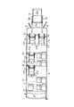
以下、本発明を図面に基づいて説明する。図1は、本発明に係るシートベルト装置を装備した乗合自動車の一例であるマイクロバスを示しており、図2および図3は当該シートベルト装置を車椅子に装着した状態を示している。
【0011】
マイクロバス10は、車椅子用固定装置および車椅子用リフタを装備しているもので、車室11内における車椅子20の各配置部位11a,11b,11c,11dに車椅子固定装置20aおよびシートベルト装置30が配設され、かつ、車体12の後側の乗降口12aにリフタ13が配設されている。車椅子20の各配置部位11a,11b,11c,11dのうち、配置部位11a,11bは車椅子専用の配置スペースであり、配置部位11c,11dは車両用シート14と車椅子20との兼用の配置スペースである。配置部位11c,11dには、車両用シート14が取外し可能に取付けられていて、必要により車両用シート14を取外すことによって車椅子20の配置部位を増加させるようになっている。
【0012】
リフタ13は、昇降可能なプラットホーム13aを備えていて、プラットホーム13aは非使用時には起立状態に格納されていて、後部ドア15にて覆蓋されており、使用時には後部ドア15を開放して、プラットホーム13aを水平状態に開いて水平状態を保持して下降および上昇させる。プラットホーム13aのこれらの動作は、プラットホーム13aの開閉スイッチおよび昇降スイッチの操作により行われる。介護者は、人が着座する車椅子20を下降しているプラットホーム13aに載せ、この状態で、プラットホーム13aを車室フロアと同一の高さに上昇させて、車椅子20を車室11内に乗込ませる。この間、車椅子の着座者は、リフタ13の左右の手すり13bを把持することができる。乗込ませた車椅子20は、各配置部位11a,11b,11c,11dのいずれかに移動して停止され、車椅子用固定装置20aにより、配置部位11a,11b,11c,11dのいずれかの車室フロアに固定される。本発明に係る車椅子用シートベルト装置30は、車椅子20の各配置部位11a,11b,11c,11dに装備されている。
【0013】
シートベルト装置30は、図2および図3に示すように、リトラクタ31、シートベルト32、第1のベルトアンカ33、第2のベルトアンカ34、ガイド部材35、第1のタング36および第2のタング37を備えている。
【0014】
リトラクタ31は公知のもので、車室11の側壁の下方の部位に取付けられている。シートベルト32は、リトラクタ31から任意の長さ引出し可能なもので、第1のタング36が挿通され、かつ、その先端部には第2のタング37が取付けられている。第1のベルトアンカ33は、取付金具30aを介して車室11のフロア上に離脱可能に取付けられている。第1のベルトアンカ33においては、そのベルト部33bの先端部にバックル33aが設けられている。バックル33aには、シートベルト32に挿通した第1のタング36が離脱可能に嵌着される。第2のベルトアンカ34は、車室11の側壁の下方の部位でリトラクタ31の近傍に取付けられており、その先端部にバックル34aが設けられている。バックル34aには、シートベルト32の先端部に設けた第2のタング37が離脱可能に嵌着される。
【0015】
ガイド部材35は、車室11内の側壁の上方の部位に設けられて窓部16の上方の部位に沿って前後に延びる手すりパイプ17のガイドパイプ17aに取付けられているもので、シートベルト32が挿通するスリット状孔部35aを備えている。ガイド部材35は、リトラクタ31の上方に位置していて、リトラクタ31から引出されて延びるシートベルト32をスリット状孔部35aに挿通させていて、方向変換を図るべく機能する。従って、ガイド部材35は、シートベルト32のショルダアンカとして機能する。
【0016】
第1のベルトアンカ33を車室11のフロアに取付ける取付金具30aは、図4に示すように、フロア側に取付けられている固定具38と、第1のベルトアンカ33側に固定されている連結具39とにより構成されている。固定具38は、円盤状座部38aの前端部から上方かつ後方へ屈曲して延びるアーム部38bと、円盤状座部38aの後端部から上方かつ前方へ屈曲して延びるアーム部38cを備えていて、両アーム部38b,38cの上端部間は瓢箪形の開口部38dになっており、また、両アーム部38b,38cの頂部38eは円形状の平坦部になっている。
【0017】
連結具39は、連結具本体39aと、連結具本体39aの中央部を上下に摺動可能に貫通するロッド部39bと、ロッド部39bの下端部に一体の円盤状の掛止部39cを備え、連結具本体39aとロッド部39b間には図示しないバネが介装されている。ロッド部39bは、バネの作用にて上方へ移動して掛止部39cを、連結具本体39aが有する両突片39d内に位置させている。連結具39は、そのロッド部39bの上端にて第1のベルトアンカ33を構成するベルト部33bの下端に連結されている。
【0018】
取付金具30aにおいては、図4(a)に示すように、取外された状態の連結具39のロッド部39bをバネに抗して押動した状態で、車室11のフロアに固定されている固定具38の開口部38dの一側から両アーム部38b,38cの上端縁の隙間にはめ込んで、両アーム部38b,38cの頂部38eに位置させる。これにより、連結具本体39aの本体底部39eと掛止部39cが両アーム部38b,38cの頂部38eを上下両側から挟持するとともに、連結具本体39aの両突片39dが開口部38dの左右の両大径部に嵌合する。これにより、連結具39は、同図(b)に示すように固定具38に連結される。
【0019】
この連結状態では、連結具39は固定具38に対して上下動および左右動を規制されて固定状態にあり、第1のベルトアンカ33を車室11のフロアに取付けている。この取付け状態において、第1のベルトアンカ33を車室11のフロアから取外すには、連結具39のロッド部39bをバネに抗して押し下げ、この状態を維持して、連結具本体39aを引き上げつつ側方へ引き抜く。連結具本体39aの引き上げにより、両突片39dが開口部38dの左右の両大径部から抜け出て連結具39の左右動が可能となり、連結具39を開口部38dの一側へ移動さて固定具38から離脱させる。これにより、第1のベルトアンカ33はフロアから取外される。
【0020】
このように構成したシートベルト装置30においては、リトラクタ31から上方へ引出したシートベルト32をガイド部材35にて方向変換して、車椅子20の前方へ導くことができる。このため、図2に示すように、シートベルト32に挿通されている第1のタング36を、車椅子20の左右の内側の肘掛け21の下方および車輪22のスポーク間を通して車室11のフロア側の第1のベルトアンカ33に導いて、同ベルトアンカ33のバックル33aに嵌着して固定し、かつ、シートベルト32の先端部に設けた第2のタング37を、車椅子20の左右の外側の肘掛け23の下方および車輪24のスポーク間を通して車室11の側壁側の下方の部位の第2のベルトアンカ34に導いて、同ベルトアンカ34のバックル34aに嵌着して固定する。
【0021】
これにより、シートベルト32においては、ガイド部材35から車椅子20の着座者の肩部、胴部および腰部を経て第1のベルトアンカ33に至る第1のベルト部と、第1のベルトアンカ33から車椅子20の着座者の腰部の一方から他方を経て第2のベルトアンカ34に至る第2のベルト部を有する3点式のシートベルトに構成される。
【0022】
このように、当該シートベルト装置30によれば、2点式のシートベルトに比較して機能的に優れた3点式のシートベルトを簡単な操作で構成することができるが、当該シートベルト装置30によれば、ショルダアンカとして機能するガイド部材35を、車室11内の側壁の上方の部位に取付けられて窓部16の上方の部位に沿って前後に延びる手すりパイプ17に設けるようにしているため、車椅子20の配置部位を車室11の側壁に沿って多くの部位に設定しても、当該設定部位に対応してシートベルト装置30を容易に配設することができる。
【0023】
また、当該シートベルト装置30においては、第1のベルトアンカ33を車室11のフロアに取付金具30aを介して取外し可能に取付けているため、車椅子20を搭載していない場合には、第1のベルトアンカ33をフロアから容易に取外して、乗員の移動に対する不自由さを解消することができる。このため、シートベルト装置30の設置の規制を大幅に緩和することができる。
【図面の簡単な説明】
【図1】本発明のシートベルト装置を装備した自動車の屋根を省略した状態の、車両用シート、車椅子、車椅子固定装置、およびシートベルト装置の配設レイアウトを概略的に示す平面図である。
【図2】同シートベルト装置を車椅子の正面側から見た状態の斜視図である。
【図3】同シートベルト装置を車椅子の左後方側から見た状態の斜視図である。
【図4】同シートベルト装置を構成する第1のベルトアンカをフロアに取付けるための取付金具で、同取付金具を構成する連結具を固定具から取外した状態の斜視図(a)、および連結具を固定具に連結した状態の斜視図(b)である。
【符号の説明】
10…マイクロバス、11…車室、11a,11b,11c,11d…車椅子の配置部位、12…車体、12a…乗降口、13…リフタ、13a…プラットホーム、13b…手すり、14…車両用シート、15…後部ドア、16…窓部、17…手すりパイプ、17a…ガイドパイプ、20…車椅子、2oa…車椅子用固定装置、21,23…肘掛け、22,24…車輪、30…シートベルト装置、30a…取付金具、31…リトラクタ、32…シートベルト、33…第1のベルトアンカ、33a…バックル、33b…ベルト部、34…第2のベルトアンカ、34a…バックル、35…ガイド部材、35a…スリット状孔部、36…第1のタング、37…第2のタング、38…固定具、38a…円盤状座部、38b…アーム部、38c…アーム部、38d…開口部、38e…頂部、39…連結具、39a…連結具本体、39b…ロッド部、39c…掛止部、39d…突片、39e…本体底部。[0001]
BACKGROUND OF THE INVENTION
The present invention relates to a seatbelt device for holding a wheelchair seated person mounted on a passenger car and fixed to a passenger compartment floor.
[0002]
[Prior art]
In shared cars, such as buses and vans, where a disabled person is seated in a wheelchair, a vehicle that can be used with the wheelchair has been developed. Wheelchair seat belt devices have also been developed to hold wheelchair occupants. Generally, in a seat belt device for a vehicle, there are a two-point seat belt device and a three-point seat belt device, and the functional three-point seat belt device is excellent.
[0003]
[Problems to be solved by the invention]
By the way, the seat belt device for wheelchairs in a shared vehicle proposed so far is a two-point seat belt device due to special structural restrictions in the passenger compartment of the shared vehicle, which is more functionally superior. A three-point seat belt device is desired. Accordingly, an object of the present invention is to provide a seat belt device for a wheelchair having a three-point seat belt that can be used by a wheelchair seated in a shared vehicle.
[0004]
[Means for Solving the Problems]
The present invention relates to a seat belt device for holding a wheelchair seated person mounted on a passenger car and fixed to a passenger compartment floor.
[0005]
Thus, the seat belt device according to the present invention includes a retractor disposed in a lower portion of a side wall of the passenger car, a seat belt that can be pulled out from the retractor, and a first floor belt provided on the passenger compartment floor. A belt anchor, a second belt anchor provided at a portion below the side wall of the passenger compartment, and a seat belt provided at a handrail portion provided at a portion above the side wall of the passenger compartment and pulled out from the retractor are inserted. A guide member that changes direction, a first tongue that is inserted into the seat belt and is detachably fitted to a buckle provided in the first belt anchor, and a first tongue that is attached to a front end portion of the seat belt. And a second tongue that is detachably fitted to a buckle provided on the belt anchor of No. 2.
[0006]
In the wheelchair seat belt device according to the present invention, it is preferable that the first belt anchor is detachably provided on the vehicle compartment floor.
[0007]
[Operation and effect of the invention]
In the seat belt device according to the present invention, the direction of the seat belt drawn upward from the retractor can be changed by the guide member and guided to the front of the wheelchair. For this reason, the first tongue inserted through the seat belt is guided to the first belt anchor side of the passenger compartment floor through the armrests on the left and right sides of the wheelchair or between the spokes of the wheel, and is attached to the buckle of the belt anchor. The second belt anchor at the lower part of the compartment side wall is inserted and fixed and the second tongue provided at the front end of the seat belt is passed through between the armrests on the other side of the wheelchair and the spokes of the wheel. Lead to the side and fit and fix to the buckle of the same belt anchor.
[0008]
Thus, in the seat belt device according to the present invention, the first belt portion from the guide member to the first belt anchor through the shoulder, torso and waist of the wheelchair seated person, and the first belt anchor. A three-point seat belt is provided that has a second belt portion that reaches the second belt anchor through one and the other of the waists of a wheelchair seated person, and in which the guide member functions as a shoulder anchor.
[0009]
In addition, in the seat belt device for wheelchairs according to the present invention, if the first belt anchor is provided so as to be removable from the passenger compartment floor, when the wheelchair is not used and the seat belt device is not used. Can remove the first belt anchor from the passenger compartment floor to eliminate the inconvenience when the occupant moves due to the presence of the first belt anchor.
[0010]
DETAILED DESCRIPTION OF THE INVENTION
Hereinafter, the present invention will be described with reference to the drawings. FIG. 1 shows a microbus which is an example of a passenger car equipped with a seat belt device according to the present invention, and FIGS. 2 and 3 show a state in which the seat belt device is mounted on a wheelchair.
[0011]
The microbus 10 is equipped with a wheelchair fixing device and a wheelchair lifter, and the
[0012]
The
[0013]
2 and 3, the
[0014]
The
[0015]
The
[0016]
As shown in FIG. 4, the mounting
[0017]
The
[0018]
As shown in FIG. 4A, the mounting
[0019]
In this connected state, the connecting
[0020]
In the
[0021]
As a result, in the
[0022]
As described above, according to the
[0023]
Moreover, in the said
[Brief description of the drawings]
FIG. 1 is a plan view schematically showing an arrangement layout of a vehicle seat, a wheelchair, a wheelchair fixing device, and a seatbelt device in a state where a roof of an automobile equipped with a seatbelt device of the present invention is omitted.
FIG. 2 is a perspective view of the seat belt device as viewed from the front side of the wheelchair.
FIG. 3 is a perspective view of the seat belt device viewed from the left rear side of the wheelchair.
FIG. 4 is a mounting bracket for mounting the first belt anchor constituting the seat belt device to the floor, and a perspective view (a) in a state in which the coupler constituting the fitting is removed from the fixture, and the coupling It is a perspective view (b) of the state which connected the tool to the fixing tool.
[Explanation of symbols]
DESCRIPTION OF SYMBOLS 10 ... Microbus, 11 ... Car compartment, 11a, 11b, 11c, 11d ... Wheelchair arrangement part, 12 ... Vehicle body, 12a ... Entrance / exit, 13 ... Lifter, 13a ... Platform, 13b ... Handrail, 14 ... Vehicle seat, 15 ... rear door, 16 ... window, 17 ... handrail pipe, 17a ... guide pipe, 20 ... wheelchair, 2oa ... wheelchair fixing device, 21, 23 ... armrest, 22, 24 ... wheel, 30 ... seat belt device, 30a ... Mounting bracket, 31 ... retractor, 32 ... seat belt, 33 ... first belt anchor, 33a ... buckle, 33b ... belt portion, 34 ... second belt anchor, 34a ... buckle, 35 ... guide member, 35a ... slit
Claims (2)
Translated fromJapanesePriority Applications (1)
| Application Number | Priority Date | Filing Date | Title |
|---|---|---|---|
| JP22008799AJP4144126B2 (en) | 1999-08-03 | 1999-08-03 | Seat belt device for wheelchair in passenger car |
Applications Claiming Priority (1)
| Application Number | Priority Date | Filing Date | Title |
|---|---|---|---|
| JP22008799AJP4144126B2 (en) | 1999-08-03 | 1999-08-03 | Seat belt device for wheelchair in passenger car |
Publications (2)
| Publication Number | Publication Date |
|---|---|
| JP2001047969A JP2001047969A (en) | 2001-02-20 |
| JP4144126B2true JP4144126B2 (en) | 2008-09-03 |
Family
ID=16745732
Family Applications (1)
| Application Number | Title | Priority Date | Filing Date |
|---|---|---|---|
| JP22008799AExpired - LifetimeJP4144126B2 (en) | 1999-08-03 | 1999-08-03 | Seat belt device for wheelchair in passenger car |
Country Status (1)
| Country | Link |
|---|---|
| JP (1) | JP4144126B2 (en) |
Families Citing this family (14)
| Publication number | Priority date | Publication date | Assignee | Title |
|---|---|---|---|---|
| WO2006067889A1 (en)* | 2004-12-24 | 2006-06-29 | Matunaga Manufactory Co., Ltd. | On-vehicle stretcher and lifter |
| JP5260389B2 (en)* | 2009-03-31 | 2013-08-14 | 株式会社オーテックジャパン | Seat belt holder |
| KR101139764B1 (en) | 2009-07-10 | 2012-06-12 | (주)유프랜드 | Safety belt for wheelchair |
| WO2011021471A1 (en)* | 2009-08-18 | 2011-02-24 | トヨタ車体株式会社 | Seatbelt device for wheelchair |
| JP6221643B2 (en)* | 2013-11-01 | 2017-11-01 | ダイムラー・アクチェンゲゼルシャフトDaimler AG | Vehicle wheelchair fixing device |
| JP7200854B2 (en)* | 2019-06-28 | 2023-01-10 | トヨタ自動車株式会社 | Wheelchair boarding information system |
| JP7147698B2 (en) | 2019-07-04 | 2022-10-05 | トヨタ自動車株式会社 | Wheelchair occupant restraint system |
| JP7156188B2 (en) | 2019-07-04 | 2022-10-19 | トヨタ自動車株式会社 | Wheelchair occupant restraint system |
| JP2021023665A (en)* | 2019-08-07 | 2021-02-22 | トヨタ自動車株式会社 | vehicle |
| JP7183992B2 (en) | 2019-08-08 | 2022-12-06 | トヨタ自動車株式会社 | shared car |
| JP7298389B2 (en) | 2019-08-23 | 2023-06-27 | トヨタ自動車株式会社 | Wheelchair lashing structure |
| JP7192713B2 (en) | 2019-08-23 | 2022-12-20 | トヨタ自動車株式会社 | vehicle interlock system |
| JP7167895B2 (en)* | 2019-10-15 | 2022-11-09 | トヨタ自動車株式会社 | shared car |
| JP7188364B2 (en) | 2019-11-25 | 2022-12-13 | トヨタ自動車株式会社 | wheelchair passenger restraint structure |
- 1999
- 1999-08-03JPJP22008799Apatent/JP4144126B2/ennot_activeExpired - Lifetime
Also Published As
| Publication number | Publication date |
|---|---|
| JP2001047969A (en) | 2001-02-20 |
Similar Documents
| Publication | Publication Date | Title |
|---|---|---|
| JP4144126B2 (en) | Seat belt device for wheelchair in passenger car | |
| CN110949209B (en) | Vehicle seat and vehicle seat arrangement structure | |
| US4103934A (en) | Folding seat and wheelchair restraint | |
| US5022677A (en) | Motor vehicle seat featuring two seat belts | |
| US8042866B2 (en) | Vehicle occupant restraint belt system | |
| US6095604A (en) | Child seat mounting system | |
| US3829123A (en) | Seat belt positioner | |
| US5538283A (en) | Automobile armrest apparatus for presenting restaint system | |
| JP3869857B2 (en) | Safety belt structure | |
| JPH0367752A (en) | Device for receiving height-adjustably upper belt hinge point and belt turn point | |
| US4373747A (en) | Passive safety belt device | |
| JP2009220672A (en) | Seat belt device | |
| JPH02147454A (en) | Passive seat belt | |
| JP4345431B2 (en) | Seat with armrest | |
| JPS61278451A (en) | Seat belt putting on and putting off device | |
| KR101039674B1 (en) | Wheelchair combined driver seat structure of car | |
| JP2010105438A (en) | Vehicular seat | |
| KR20040042946A (en) | Structure for mounting center seat of vehicle | |
| JPS6119961Y2 (en) | ||
| KR20240055913A (en) | Mobility driven by a person who sits in a wheelchair on drivers seat | |
| JP2981936B2 (en) | Seat lifting device | |
| JPS598913Y2 (en) | Inner side belt lifting device in passive belt device | |
| EP0374973A2 (en) | Motor vehicle seat fitted with a seat belt | |
| JP4101594B2 (en) | Seat belt structure | |
| JPH0438242A (en) | Seat belt for vehicle |
Legal Events
| Date | Code | Title | Description |
|---|---|---|---|
| A711 | Notification of change in applicant | Free format text:JAPANESE INTERMEDIATE CODE: A712 Effective date:20041126 | |
| A521 | Written amendment | Free format text:JAPANESE INTERMEDIATE CODE: A523 Effective date:20050131 | |
| RD02 | Notification of acceptance of power of attorney | Free format text:JAPANESE INTERMEDIATE CODE: A7422 Effective date:20050407 | |
| A621 | Written request for application examination | Free format text:JAPANESE INTERMEDIATE CODE: A621 Effective date:20060117 | |
| TRDD | Decision of grant or rejection written | ||
| A01 | Written decision to grant a patent or to grant a registration (utility model) | Free format text:JAPANESE INTERMEDIATE CODE: A01 Effective date:20080527 | |
| A01 | Written decision to grant a patent or to grant a registration (utility model) | Free format text:JAPANESE INTERMEDIATE CODE: A01 | |
| A977 | Report on retrieval | Free format text:JAPANESE INTERMEDIATE CODE: A971007 Effective date:20080529 | |
| A61 | First payment of annual fees (during grant procedure) | Free format text:JAPANESE INTERMEDIATE CODE: A61 Effective date:20080609 | |
| R150 | Certificate of patent or registration of utility model | Free format text:JAPANESE INTERMEDIATE CODE: R150 Ref document number:4144126 Country of ref document:JP Free format text:JAPANESE INTERMEDIATE CODE: R150 | |
| FPAY | Renewal fee payment (event date is renewal date of database) | Free format text:PAYMENT UNTIL: 20110627 Year of fee payment:3 | |
| FPAY | Renewal fee payment (event date is renewal date of database) | Free format text:PAYMENT UNTIL: 20120627 Year of fee payment:4 | |
| FPAY | Renewal fee payment (event date is renewal date of database) | Free format text:PAYMENT UNTIL: 20120627 Year of fee payment:4 | |
| FPAY | Renewal fee payment (event date is renewal date of database) | Free format text:PAYMENT UNTIL: 20130627 Year of fee payment:5 | |
| FPAY | Renewal fee payment (event date is renewal date of database) | Free format text:PAYMENT UNTIL: 20130627 Year of fee payment:5 | |
| FPAY | Renewal fee payment (event date is renewal date of database) | Free format text:PAYMENT UNTIL: 20140627 Year of fee payment:6 | |
| R250 | Receipt of annual fees | Free format text:JAPANESE INTERMEDIATE CODE: R250 | |
| R250 | Receipt of annual fees | Free format text:JAPANESE INTERMEDIATE CODE: R250 | |
| R250 | Receipt of annual fees | Free format text:JAPANESE INTERMEDIATE CODE: R250 | |
| R250 | Receipt of annual fees | Free format text:JAPANESE INTERMEDIATE CODE: R250 | |
| R250 | Receipt of annual fees | Free format text:JAPANESE INTERMEDIATE CODE: R250 | |
| R250 | Receipt of annual fees | Free format text:JAPANESE INTERMEDIATE CODE: R250 | |
| R250 | Receipt of annual fees | Free format text:JAPANESE INTERMEDIATE CODE: R250 | |
| EXPY | Cancellation because of completion of term |