JP4140751B2 - Vehicle lighting device - Google Patents
Vehicle lighting deviceDownload PDFInfo
- Publication number
- JP4140751B2 JP4140751B2JP2001135901AJP2001135901AJP4140751B2JP 4140751 B2JP4140751 B2JP 4140751B2JP 2001135901 AJP2001135901 AJP 2001135901AJP 2001135901 AJP2001135901 AJP 2001135901AJP 4140751 B2JP4140751 B2JP 4140751B2
- Authority
- JP
- Japan
- Prior art keywords
- deflection angle
- vehicle
- lamp
- speed
- maximum deflection
- Prior art date
- Legal status (The legal status is an assumption and is not a legal conclusion. Google has not performed a legal analysis and makes no representation as to the accuracy of the status listed.)
- Expired - Fee Related
Links
Images


Classifications
- B—PERFORMING OPERATIONS; TRANSPORTING
- B60—VEHICLES IN GENERAL
- B60Q—ARRANGEMENT OF SIGNALLING OR LIGHTING DEVICES, THE MOUNTING OR SUPPORTING THEREOF OR CIRCUITS THEREFOR, FOR VEHICLES IN GENERAL
- B60Q1/00—Arrangement of optical signalling or lighting devices, the mounting or supporting thereof or circuits therefor
- B60Q1/02—Arrangement of optical signalling or lighting devices, the mounting or supporting thereof or circuits therefor the devices being primarily intended to illuminate the way ahead or to illuminate other areas of way or environments
- B60Q1/04—Arrangement of optical signalling or lighting devices, the mounting or supporting thereof or circuits therefor the devices being primarily intended to illuminate the way ahead or to illuminate other areas of way or environments the devices being headlights
- B60Q1/06—Arrangement of optical signalling or lighting devices, the mounting or supporting thereof or circuits therefor the devices being primarily intended to illuminate the way ahead or to illuminate other areas of way or environments the devices being headlights adjustable, e.g. remotely-controlled from inside vehicle
- B60Q1/08—Arrangement of optical signalling or lighting devices, the mounting or supporting thereof or circuits therefor the devices being primarily intended to illuminate the way ahead or to illuminate other areas of way or environments the devices being headlights adjustable, e.g. remotely-controlled from inside vehicle automatically
- B60Q1/12—Arrangement of optical signalling or lighting devices, the mounting or supporting thereof or circuits therefor the devices being primarily intended to illuminate the way ahead or to illuminate other areas of way or environments the devices being headlights adjustable, e.g. remotely-controlled from inside vehicle automatically due to steering position
- B—PERFORMING OPERATIONS; TRANSPORTING
- B60—VEHICLES IN GENERAL
- B60Q—ARRANGEMENT OF SIGNALLING OR LIGHTING DEVICES, THE MOUNTING OR SUPPORTING THEREOF OR CIRCUITS THEREFOR, FOR VEHICLES IN GENERAL
- B60Q1/00—Arrangement of optical signalling or lighting devices, the mounting or supporting thereof or circuits therefor
- B60Q1/02—Arrangement of optical signalling or lighting devices, the mounting or supporting thereof or circuits therefor the devices being primarily intended to illuminate the way ahead or to illuminate other areas of way or environments
- B60Q1/04—Arrangement of optical signalling or lighting devices, the mounting or supporting thereof or circuits therefor the devices being primarily intended to illuminate the way ahead or to illuminate other areas of way or environments the devices being headlights
- B60Q1/18—Arrangement of optical signalling or lighting devices, the mounting or supporting thereof or circuits therefor the devices being primarily intended to illuminate the way ahead or to illuminate other areas of way or environments the devices being headlights being additional front lights
- B—PERFORMING OPERATIONS; TRANSPORTING
- B60—VEHICLES IN GENERAL
- B60Q—ARRANGEMENT OF SIGNALLING OR LIGHTING DEVICES, THE MOUNTING OR SUPPORTING THEREOF OR CIRCUITS THEREFOR, FOR VEHICLES IN GENERAL
- B60Q11/00—Arrangement of monitoring devices for devices provided for in groups B60Q1/00 - B60Q9/00
- B—PERFORMING OPERATIONS; TRANSPORTING
- B60—VEHICLES IN GENERAL
- B60Q—ARRANGEMENT OF SIGNALLING OR LIGHTING DEVICES, THE MOUNTING OR SUPPORTING THEREOF OR CIRCUITS THEREFOR, FOR VEHICLES IN GENERAL
- B60Q2200/00—Special features or arrangements of vehicle headlamps
- B60Q2200/30—Special arrangements for adjusting headlamps, e.g. means for transmitting the movements for adjusting the lamps
- B60Q2200/38—Automatic calibration of motor-driven means for adjusting headlamps, i.e. when switching on the headlamps, not during mounting at factories
- B—PERFORMING OPERATIONS; TRANSPORTING
- B60—VEHICLES IN GENERAL
- B60Q—ARRANGEMENT OF SIGNALLING OR LIGHTING DEVICES, THE MOUNTING OR SUPPORTING THEREOF OR CIRCUITS THEREFOR, FOR VEHICLES IN GENERAL
- B60Q2300/00—Indexing codes for automatically adjustable headlamps or automatically dimmable headlamps
- B60Q2300/10—Indexing codes relating to particular vehicle conditions
- B60Q2300/11—Linear movements of the vehicle
- B60Q2300/112—Vehicle speed
- B—PERFORMING OPERATIONS; TRANSPORTING
- B60—VEHICLES IN GENERAL
- B60Q—ARRANGEMENT OF SIGNALLING OR LIGHTING DEVICES, THE MOUNTING OR SUPPORTING THEREOF OR CIRCUITS THEREFOR, FOR VEHICLES IN GENERAL
- B60Q2300/00—Indexing codes for automatically adjustable headlamps or automatically dimmable headlamps
- B60Q2300/10—Indexing codes relating to particular vehicle conditions
- B60Q2300/11—Linear movements of the vehicle
- B60Q2300/114—Vehicle acceleration or deceleration
- B—PERFORMING OPERATIONS; TRANSPORTING
- B60—VEHICLES IN GENERAL
- B60Q—ARRANGEMENT OF SIGNALLING OR LIGHTING DEVICES, THE MOUNTING OR SUPPORTING THEREOF OR CIRCUITS THEREFOR, FOR VEHICLES IN GENERAL
- B60Q2300/00—Indexing codes for automatically adjustable headlamps or automatically dimmable headlamps
- B60Q2300/10—Indexing codes relating to particular vehicle conditions
- B60Q2300/11—Linear movements of the vehicle
- B60Q2300/116—Vehicle at a stop
- B—PERFORMING OPERATIONS; TRANSPORTING
- B60—VEHICLES IN GENERAL
- B60Q—ARRANGEMENT OF SIGNALLING OR LIGHTING DEVICES, THE MOUNTING OR SUPPORTING THEREOF OR CIRCUITS THEREFOR, FOR VEHICLES IN GENERAL
- B60Q2300/00—Indexing codes for automatically adjustable headlamps or automatically dimmable headlamps
- B60Q2300/10—Indexing codes relating to particular vehicle conditions
- B60Q2300/12—Steering parameters
- B60Q2300/122—Steering angle
Landscapes
- Engineering & Computer Science (AREA)
- Mechanical Engineering (AREA)
- Lighting Device Outwards From Vehicle And Optical Signal (AREA)
- Non-Portable Lighting Devices Or Systems Thereof (AREA)
Description
Translated fromJapanese【0001】
【発明の属する技術分野】
本発明は自動車等の車両の照明装置に関し、特に走行状況に対応してランプ光の照射方向を追従変化させるランプ偏向角度制御手段、例えば適応型照明システム(以下、AFS(Adaptive Front-lighting System))を備える車両用照明装置において、車速変化に対応した適正な照射方向の設定を可能にした車両用照明装置に関するものである。
【0002】
【従来の技術】
自動車の走行安全性を高めるために提案されているAFSは、図1に概念図を示すように、自動車のステアリングホイールSWの操舵角、自動車の速度、その他自動車の走行状況を示す情報をセンサ1により検出してその検出出力を電子制御ユニット(以下、ECU(Electronic Controll Unit)2に入力し、ECU2は入力されたセンサ出力に基づいて自動車の前部の左右にそれぞれ装備されたスイブル式灯具3R,3L、すなわち照射方向を左右方向に偏向制御可能な前照灯3を制御するようにしたものである。このような前照灯としては、例えば前照灯内に設けられているリフレクタを水平方向に回動可能な構成としてリフレクタをモータ等の駆動力源によって回転駆動する構成のものがあり、この回転駆動するための機構をここではアクチュエータと称している。この種のAFSによれば、自動車がカーブした道路を走行する際には、当該自動車の走行速度に対応してカーブ先の道路を照明することが可能になり、走行安全性を高める上で有効である。
【0003】
【発明が解決しようとする課題】
通常この種のAFSでは、低速走行時には自車の前方近傍領域である直前領域を運転者が視認できるように照明することが好ましく、また高速走行時には自車の前方の相当距離離れた領域である前遠方領域を運転者が視認できるように照明することが好ましいが、従来のAFSでは照射方向が最大に偏向可能な角度である最大偏向角度については特に考慮されておらず、例えば低速走行時と高速走行時のいずれにおいても前照灯の最大偏向角度は一義的に定められている。そのため、低速走行時のカーブ走行時に自車の進行方向の直前領域を適正に照明するために照射方向を大きく変化させることができるように最大偏向角度を大きく設定すると、高速走行時に照射方向が大きく変化され過ぎて自車の進行方向の前遠方領域から左右に大きくずれた領域を照明する状況が生じてしまうこともあり(同じ偏向角度でも遠方ほど照明領域の左右方向の変化量が大きくなるため)、AFSによる適正な照明ができなくなる。特に、高速走行時に緩やかなカーブを走行するような場合に照射方向が大きく変化されると自車の進行方向の前遠方領域の照明が不十分になり交通安全性の点で問題となる。逆に、高速走行時に適正な照明が行われるように照射方向の変化を抑制すべく最大偏向角度を小さく設定すると、低速走行時はカーブ道路、特に交差点のように大きく進路変更する道路において照射方向の変化が不十分になり自車の進行方向の直前領域を適正に照明することができなくなる。
【0004】
また、自車が徐行ないし停車する程度の低速時、特に自車を駐車場に駐車したり車庫入れするような状態のときに、ステアリングホイールを切返し操作したときにAFSが動作すると、前照灯の照射方向が左右に大きく偏向されるため、自車の直進方向の直前領域を照明することができなくなり、安全確認の上で好ましくない状況が生じる。また、このように停車に近い状態のときに前照灯の照射方向が大きく偏向されることは乗員にとって煩わしく感じるものとなり、場合によっては近くを通る自動車や歩行者を眩惑して交通安全の面でも好ましくないものになる。
【0005】
本発明の目的は、車両速度に追従して適正な照明を行うようにした車両用照明装置を提供するものである。
【0006】
【課題を解決するための手段】
本発明は、車両の操舵方向を検出する操舵角センサを有し、操舵角センサの出力に基づいてランプの照射方向の偏向角度を変化制御するランプ偏向角度制御手段を備える車両用照明装置において、車両の走行速度を検出する車速センサを備えるとともに、ランプ偏向角度制御手段は当該車速センサで検出される車速に基づいてランプの偏向角度の最大偏向角度を制御するように構成し、ランプ偏向角度制御手段は、車両が停車に近い状態のときに前記最大偏向角度を0°にし、それよりも速度が増大された第1の所定速度のときに最大偏向角度を最大角にし、第1の所定速度以上の巡行走行状態のときにはさらに高速の第2の所定速度において所定の最大偏向角度に達するまで車速の増加に伴って最大偏向角度を徐々に低減するように構成する。あるいは、ランプ偏向角度制御手段は、車両が停車に近い状態のときに前記最大偏向角度を0°にし、それよりも速度が増大されて車両が第1の所定速度に達するまでの過渡走行状態のときに最大偏向角度を車速の増大に伴って増加し、第1の所定速度以上の巡行走行状態のときにはさらに高速の第2の所定速度において所定の最大偏向角度に達するまで車速の増加に伴って前記最大偏向角度を徐々に低減するように構成する。
【0007】
本発明によれば、車両が停車に近い走行状態のときには、ランプの最大偏向角度を0°にすることで、車両の徐行時、あるいは停車・駐車時、さらには車庫入れ等の状態のときにランプの照射方向は車両の直進方向に向けて固定されることになり、自動車の近傍領域を安定な状態で照明して近くを通る自動車や歩行者を眩惑することはなく、また前照灯の照射方向が大きく偏向されて煩わしく感じるようなことはない。また、車両が高速に近い巡行走行状態のときには、車速が高速になるのに従い最大偏向角度が抑制されるため、ランプの偏向角度は車両の直進方向に近い角度範囲内で制御され、車両の操舵状況にかかわらず進行方向前方の相当距離離れた直進近傍領域を照明することができ、ランプの偏向角度が左右に振れることが抑制される。また、速度が徐々に低下したときには、最大偏向角度の制限が緩和されるため、カーブ道路での進行方向の直前領域を適正に照明することは可能になる。さらに、停車状態から巡行走行状態の間の過渡走行状態のときには車速が低速になるのに従い最大偏向角度信号が制限されるので、停車状態と巡行走行状態との間における最大偏向角度の変化の連続性を保ち、停車・発進時等におけるランプの照射方向が急激に変化することが回避でき、乗員に不安感を生じさせるようなことはない。
【0008】
【発明の実施の形態】
次に、本発明の実施形態を図面を参照して説明する。図2は図1に示した本発明のランプ偏向角度制御手段としてのAFSの構成要素のうち、照射方向を左右に偏向可能なスイブル式灯具で構成した前照灯の左側灯具3Lの縦断面図、図3はその内部構造の部分分解斜視図である。灯具ボディ11の前部開口にはレンズ12が、後部開口にはカバー13がそれぞれ取着されて灯室14を形成しており、当該灯室14内には上板151、下板152を有する棚状をした固定ブラケット15が内装されており、この固定ブラケット15の上部に固定リフレタク21が取着され、下部にスイブルリフレクタ31が支持されている。前記固定リフレクタ21は前記固定ブラケット15の上板151上にネジ22により固定されており、当該固定リフレクタ21内にはシェード24とともに放電バルブ(ディスチャージバルブ)23が取着され、自動車の正面方向に向けて所定の配光特性となる固定ランプ20として構成されている。前記スイブルリフレクタ31は前記固定ブラケット15の上板151と下板152との間に内挿され、当該スイブルリフレクタ31の上面から突出された支軸32を中心として水平方向に回動可能に嵌合支持されており、かつその内部にはシェード34とともにハロゲンバルブ33が取着されている。また、前記灯室14内の固定ブラケット15の下板152の下側には、図1に示したECU2によって駆動されるアクチュエータ4が固定支持されており、前記固定ブラケット15に設けられているステム153がネジ16によって前記アクチュエータ4の一部に固定されている。前記アクチュエータ4の回転出力軸44は前記支軸32と同軸位置において前記スイブルリフレクタ31の下面に設けた軸受部35に連結され、当該回転出力軸44の回転駆動力によって前記スイブルリフレクタ31が回転駆動され、その照明方向が左右に偏向可能なスイブルランプ30として構成されている。
【0009】
図4は前記アクチュエータ4の要部の分解斜視図、図5はその組み立て状態の縦断面図である。ケース41は下ハーフ41Dと上ハーフ41Uとで構成され、下ハーフ41Dの突起410と上ハーフ41Uの嵌合片411とが互いに嵌合される。また、前記上ハーフ41Uと下ハーフ41Dには前記固定ブラケット15を支持するための支持片412,413がそれぞれ両側に向けて突出形成されている。前記ケース41内にはプリント基板42が内装されており、後述する制御回路としての電子部品43と、前記スイブルリフレクタ31を直接的に回転駆動するための前記回転出力軸44と、前記回転出力軸44を回転駆動するための駆動源としてのブラシレスモータ45と、前記ブラシレスモータ45の回転力を前記回転出力軸44に伝達するための減速歯車機構46とが搭載されている。前記回転出力軸44には同軸にランプ偏向角度検出手段としてのポテンショメータ48が配設されている。また、前記プリント基板42には、前記ブラシレスモータ45及び前記スイブルランプ30のハロゲンランプ33にそれぞれ電力を供給するための図外の車載電源コードが接続されるコネクタ47が配設されている。また、前記上ハーフ41Uの上面には、前記アクチュエータ4と前記ハロゲンランプ33のコード36とを電気接続するための可動接点機構49が配設されている。
【0010】
前記ブラシレスモータ45は、図6に一部を破断した斜視図に示すように、前記下ハーフ41Dのボス穴414にスラスト軸受451及び軸受スリーブ452によって軸転可能に支持された回転軸453と、前記回転軸453の周囲において前記プリント基板42に固定支持されたステータコイル454と、前記回転軸453に固定されて前記ステータコイル454を覆うように被せられた円筒容器状のロータ455とを備えている。前記ロータ455はロータボス456により前記回転軸453に固定され、かつ内面には円筒状のロータマグネット457を一体に有している。前記ステータコイル454は円周方向に等配された3対のコイルで構成され、各対のコイルは前記プリント基板42の図外のプリント配線を介して給電され、当該給電により円周方向に交互にS極とN極とに磁化される構成である。前記ロータマグネット457は前記ステータコイル454に対応して円周方向に交互にS極とN極とに着磁されている。このブラシレスモータ45では、前記ステータコイル454の3つのコイルに対して位相の異なる交流、すなわち三相交流を供給することによって前記ロータマグネット457、すなわち前記ロータ455及び回転軸453を回転駆動させるものである。さらに、図6に示されるように、前記プリント基板42には前記ロータ455の円周方向に沿って所要の間隔で並んだ複数個、ここでは3個のホール素子H1,H2,H3が配列支持されており、前記ロータ455と共にロータマグネット457が回転されたときに各ホール素子H1,H2,H3における磁界が変化され、各ホール素子H1,H2,H3のON,OFF状態が変化されてロータ455の回転周期に対応したパルス信号を出力するように構成されている。
【0011】
前記ポテンショメータ48は前記プリント基板42を貫通して前記下ハーフ41Dのボス穴415に立設された固定軸481に固定され、その表面に図外の抵抗パターンが形成された固定基板482と、前記固定基板482と軸方向に対向されて前記固定軸481に回転可能に支持され前記抵抗パターンの表面で摺動される図外の摺動接点を有する回転円板483とを備えている。前記固定基板482は円周一部に設けた係合突片485が下ハーフ41Dの内壁の一部に係合することで下ハーフ41Dに対して回り止めが行われる。また、前記回転円板483の円周一部には調整片486が突出形成されている。このポテンショメータ48では、前記回転円板483の回転動作により抵抗パターンの表面上での摺動接点の摺動位置が変化されることで、前記固定基板482に設けた抵抗パターンの抵抗値が変化され、固定基板482の電極端子484から当該抵抗値が回転出力軸の回転位置、すなわちスイブルリフレクタ31の偏向角度検出信号として出力される構成となっている。
【0012】
前記回転出力軸44は前記ポテンショメータ48の前記回転円板483にクラッチ結合した構成とされており、前記ポテンショメータ48の前記固定軸481に被せられて軸転可能な中空軸部441と、前記中空軸部441の下端部に一体に設けられた短円筒状のクラッチ筒442と、前記クラッチ筒442の外周一部にわたって一体に形成されたセクタギヤ443とを有している。前記クラッチ筒442は前記回転円板483を覆うように配設されるとともに、円周一部に切欠き444が設けられ、バネ線材をほぼ円形に曲げ形成して前記回転円板の円周面に弾着されたクラッチバネ445の両端部が当該切欠き444に係合され、当該クラッチバネ445を介して前記回転円板483に回転方向に摩擦的に結合されている。したがって、前記回転円板483の円周一部に突出された調整片486を治具等により押さえて当該回転円板483の回転を係止した状態で前記回転出力軸44、すなわちクラッチ筒442を手操作により回転操作すれば、クラッチバネ445における摩擦結合により回転出力軸44を回転円板483に対して滑り回動させ、ポテンショメータ48と回転出力軸44との回転方向の相対位置調整が可能になる。この相対位置調整はポテンショメータ48の出力の零調整に利用される。
【0013】
前記減速歯車機構46は前記ブラシレスモータ45と前記ポテンショメータ48のセクタギヤ443との間の領域に配設されている。前記減速歯車機構46は前記ブラシレスモータ45の回転軸453に取着された駆動歯車461と、前記プリント基板42を貫通して前記下ハーフ41Dのボス穴416,417に所要の間隔で立設された2本の固定軸462,463にそれぞれ回転可能に軸支された第1歯車464と第2歯車465とを備えている。前記第1歯車464と第2歯車465はそれぞれ大径歯車464L,465Lと小径歯車464S,465Sが一体化され、前記駆動歯車461と第1歯車464の大径歯車464Lが噛合され、第1歯車464の小径歯車464Sと第2歯車465の大径歯車465Lが噛合され、第2歯車465の小径歯車465Sと前記セクタギヤ443が噛合されている。これにより、前記ブラシレスモータ45の回動力は減速歯車機構46により減速して前記セクタギヤ443に伝達され、前記回転出力軸44を減速回転動作させることになる。前記回転出力軸44の上端部はスプライン軸446として形成されており、前記上ハーフ41Uに開口された出力軸穴418を貫通して前記ケース41の上面側に突出されており、前記スイブルリフレクタ31の下面に設けられた軸受部35のスプライン溝に嵌合され、当該回転出力軸44の回転力によってスイブルリフレクタ31が一体的に回動されるようになっている。
【0014】
前記上ハーフ41Uの上面に配設された前記可動接点機構49は、前記ケース41内に内装されて一部が前記上ハーフ41Uの上面に開口された円周上の一対の矩形穴419を通して露出されスプリング492によって突出方向に付勢された一対の接点ブラシ491と、前記回転出力軸44のスプライン軸446が嵌合されるスプライン軸穴494を有して回転出力軸44と回転方向に一体化されて前記接点ブラシ491の上側領域において回動される接点板493とを備えている。前記接点板493は下面に前記接点ブラシ491に摺接される一対の接点片(図示せず)が延設されており、前記接点ブラシ491との電気接触を保った状態で回転出力軸44と共に回動することが可能とされている。また、前記接点板493には前記接点片につながる電極端子495が設けられており、当該電極端子495には図2に示した前記スイブルランプ30のハロゲンランプ33に接続されたコード36の図外のコネクタが着脱可能とされている。また、前記一対の接点ブラシ491はそれぞれ前記ケース41内に延設された細幅の一対の導電板496の一端に導電ワイヤ497で接続されており、当該導電板496の他端に接続される図外のコネクタにより図外の車載電源に電気接続されている。これにより、前記可動接点機構49は前記ハロゲンランプ33を車載電源に電気接続するとともにスイブルランプ30のスイブルリフレクタ31が可動した際に、スイブルランプ30とアクチュエータ4とを接続するコード36に捩じれ等が生じることを防止し、スイブルリフレクタ31の円滑な回動動作を確保する。
【0015】
図7は前記ECU2及びアクチュエータ4の電気回路構成を示すブロック回路図である。なお、アクチュエータ4はそれぞれ自動車の左右のスイブル式灯具3L,3Rに装備されたものであり、ECU2との間で双方向通信が可能とされている。前記ECU2内には前記センサ1として、ステアリングホイールSWの操舵角度を検出する操舵角センサ11と、車両の速度を検出する車速センサ12の各センサ出力が入力され、このセンサ出力の情報により所定のアルゴリズムでの処理を行なって所要の制御信号C0を出力するメインCPU201と、当該メインCPU201と前記アクチュエータ4との間で前記制御信号C0を入出力するためのインターフェース(以下、I/Fと称する)回路202と、メインCPU201を含むECU2における各種信号を監視し、異常を検出したときに異常信号を出力する異常検出回路203とを備えている。
【0016】
また、自動車の左右の各スイブル式灯具3L,3Rの各スイブルランプ30にそれぞれ設けられた前記アクチュエータ4内に内装されている電子部品で構成される制御回路43は、前記ECU2との間の信号を入出力するためのI/F回路432と、前記I/F回路432から入力される信号及び前記ホール素子H1,H2,H3から出力されるパルス信号P並びに前記ポテンショメータ48から入力される偏向角度検出信号DXに基づいて所定のアルゴリズムでの処理を行うサブCPU431と、前記I/F回路432を通して入力される信号を監視し、当該信号が異常であると判定したときに前記サブCPU431に異常信号を出力する異常検出回路433と、前記ブラシレスモータ45を回転駆動するためのモータドライブ回路434とを備えている。ここで、前記ECU2からは前記制御信号C0の一部としてスイブルランプ30の偏向角度信号DSが出力され前記アクチュエータ4に入力される。
【0017】
また、図8は前記アクチュエータ4の前記モータドライブ回路434及びブラシレスモータを模式的に示す回路図である。前記アクチュエータ4のサブCPU431から制御信号として速度制御信号V、スタート・ストップ信号S、正転・逆転信号Rがそれぞれ入力され、かつ前記3つのホール素子H1,H2,H3からのパルス信号が入力されるスイッチングマトリクス回路435と、このスイッチングマトリクス回路435の出力を受けて前記ブラシレスモータ45のステータコイル454の3対のコイルに供給する三相の電力(U相、V相、W相)の位相を調整する出力回路436とを備えている。このモータドライブ回路434では、ステータコイル454に対しU相、V相、W相の各電力を供給することによりマグネットロータ457が回転し、これと一体のロータ455及び回転軸453が回転する。マグネットロータ457が回転すると磁界の変化を各ホール素子H1,H2,H3が検出しパルス信号Pを出力し、このパルス信号Pはスイッチングマトリクス回路435に入力され、スイッチングマトリクス回路435においてパルス信号のタイミングにあわせて出力回路436でのスイッチング動作を行うことによりマグネットロータ457の回転が継続されることになる。また、前記スイッチングマトリクス回路435はサブCPU431からの速度制御信号V、スタート・ストップ信号S、正転・逆転信号Rに基づいて所要の制御信号C1を出力回路436に出力し、出力回路436はこの制御信号C1を受けてステータコイル454に供給する三相の電力の位相を調整し、ブラシレスモータ45の回転動作の開始と停止、回転方向、回転速度を制御する。また、前記アクチュエータ4に設けられているポテンショメータ48の出力はサブCPU431に入力される。このサブCPU431には前記各ホール素子H1,H2,H3から出力されるパルス信号Pの各一部がそれぞれ入力され、ブラシレスモータ45の回転状態を認識する。
【0018】
以上の構成によれば、図1に示したように自動車に配設された操舵角センサ11から当該自動車のステアリングホイールSWの操舵角の検出情報が出力され、車速センサ12から自動車の速度の情報が出力されてECU2に入力されると、ECU2は入力された情報に基づいてメインCPU201で所定のアルゴリズムでの演算を行い、自動車のスイブル式灯具3L,3Rにおけるスイブルランプ30の偏向角度信号DSを算出し両スイブル式灯具3L,3Rの各アクチュエータ4に入力する。アクチュエータ4では入力された偏向角度信号DSによりサブCPU431が演算を行い、当該偏向角度信号DSに対応した信号を算出してモータドライブ回路434に出力し、ブラシレスモータ45を回転駆動する。ブラシレイスモータ45の回転駆動力は減速歯車機構46により減速して回転出力軸44に伝達されるため、回転出力軸44に連結されているスイブルリフレクタ31が水平方向に回動し、スイブルランプ30の光軸方向が変化される。このスイブルリフレクタ31の回動動作に際しては、回転出力軸44の回転に伴いポテンショメータ48の回転円板483が回転されるため、この回転円板483の回転動作により摺動接点が固定基板482の抵抗パターンの表面上で摺動される際の抵抗値の変化に基づいて回転出力軸44の回転角度、すなわちスイブルリフレクタ31の偏向角度を検出し、当該偏向角度検出信号DXがサブCPU431に入力される。サブCPU431はこの偏向角度検出信号DXとECU2から入力される偏向角度信号DSとを比較し、両者が一致するようにブラシレスモータ45の回転角度をフィードバック制御してスイブルリフレクタ31の光軸方向、すなわちスイブルランプ30の光軸方向を当該偏向角度信号DSにより設定される角度位置に高精度に制御することが可能になる。
【0019】
このようなスイブルリフレクタ31の偏向動作により、両スイブル式灯具3L,3Rでは固定ランプ20から出射される自動車の直進方向に向けた光と、スイブルランプ30から出射される偏向された光が一体となり、自動車の直進方向から偏向された左右方向に向いた領域を照明し、自動車の走行中において自動車の直進方向のみならず操舵された方向の前方を照明することが可能になり、安全運転性を高めることが可能になる。
【0020】
また、前記異常検出回路203,433はそれぞれAFSにおける異常を検出して異常検出信号を出力し、メインCPU201及びサブCPU431はこの異常検出信号を受けてスイブルランプ30の前記した偏向状態を解消してスイブルランプ30の光軸を強制的に所定の基準偏向位置に設定することで、AFSの異常によってスイブルランプ30が偏向状態のまま光軸が調整できなくなることによる交通安全上の問題を解消することが可能とされているが、ここではその説明は省略する。
【0021】
前記ECU2のメインCPU201では、車速センサ12からの車速情報に基づいて前記偏向角度信号DSに含まれる最大偏向角度DMを制御する。図9は横軸を操舵角センサ11の出力とし縦軸をスイブルランプ30の偏向角度とした相関を示す特性図であり、ここでは便宜的に同図に破線で示すように偏向角度は操舵角度に対して所定の線形特性で変化される。そして、車速センサ12から出力される車速に応じて同図A,B,Cの各実線で示すように、最大偏向角度DMが制御されることになる。
【0022】
図10は第1の実施形態のメインCPU201における当該最大偏向角度DMの設定及びアクチュエータ4のサブCPU431における偏向角度制御のアルゴリズムを説明するためのフローチャート、図11は横軸を車速、縦軸を最大偏向角度とした相関を示す特性図である。この実施形態では、自動車の車速が5Km/h未満のときを停車状態、車速が5Km/h以上のときを巡行走行状態と定義する。その上で、メインCPU201は車速センサ12からの車速Vxを入力し(S101)、この車速Vxに基づいて自動車が停車状態か巡行走行状態かを判断する(S103)。車速Vxが5Km/h未満で停車状態にあると判断したときには、最大偏向角度DMとして0°を出力する(S105)。
【0023】
一方、ステップS103において自動車が5Km/h以上で巡行走行状態にあると判断したときには最大偏向角度が車速に反比例して線形、あるいは二次関数的に減少するような最大偏向角度DMを出力し、ここでは操舵角度信号DSの角度を変数とする関数f(DS)とする(S107)。この実施形態での関数f(DS)は、車速が増加するのに伴って最大偏向角度を図9のAの特性からBの特性の範囲で一次関数的に減少する特性の最大偏向角度DMの信号を出力し、ある程度の高速になると最大偏向角度をBの特性に固定する。
【0024】
以上のように車速に基づいて最大偏向角度DMを設定した上で、この最大偏向角度DMを情報として含む偏向角度信号DSがECU2からアクチュエータ4に出力されると(S109)、アクチュエータ4のサブCPU431では操舵角度信号DSに基づいて最大偏向角度DMの範囲内で、操舵角に応じてスイブルランプ30の偏向角度を制御する(S111)。実際には偏向角度信号DSの信号レベルの最大絶対値を最大偏向角度DMに応じて制限するように構成し、アクチュエータでは偏向角度信号DSの信号レベルの最大絶対値に基づいてブラシレスモータの最大回転量を制御することで、スイブルランプの偏向角度の最大値を制御するように構成する。
【0025】
この構成においては、自動車が停車状態(車速0〜5Km/h)のときには、最大偏向角度が0°であるため、スイブルランプ30の偏向角度は0°であり、自動車の徐行時、あるいは停車・駐車時、さらには車庫入れ等の状態のときにスイブルランプの照射方向は自動車の直進方向に向けて固定されることになり、自動車の近傍領域を安定な状態で照明して近くを通る自動車や歩行者を眩惑することはなく、また前照灯の照射方向が大きく偏向されて煩わしく感じるようなこともなくなる。
【0026】
一方、自動車が巡行走行状態(5Km/h〜)のときには、車速が高速になるのに従い最大偏向角度DMの値は徐々に低減する。そのため、ステアリングホイールSWを所定の角度だけ回転操作したときには、速度が大きくなるほどスイブルランプ30の最大偏向角度が抑制され、ECU2からの偏向角度信号DSに基づくスイブルランプ30の偏向角度は自車の直進方向に近い角度範囲内で制御されることになる。したがって、巡行走行状態においてはステアリングホイールSWの操舵状況にかかわらず自車の進行方向前方の相当距離離れた前遠方領域を照明することができ、特にステアリングホイールSWを小刻みに回動操作するような場合においてスイブルランプ30の照射方向が左右に大きく振れるようなことが回避でき、AFSによる適正な照明が確保される。なお、巡行走行状態においても速度が徐々に低下したときには、最大偏向角度DMの制限が緩和されるため、カーブ道路での進行方向の直前領域を適正に照明することは可能であり、この面での交通安全性が確保される。
【0027】
図12は第2の実施形態のメインCPU201における当該最大偏向角度DMとアクチュエータ4のサブCPU431における偏向角度制御のアルゴリズムを説明するためのフローチャートであり、図13は車速と最大偏向角度とした両者の相関を示す特性図である。第1の実施形態では車速の5Km/hを境にして最大偏向角度が大きく変化されるため、この車速近傍で偏向角度が不安定な状態が発生するおそれがある。そこで、第2の実施形態では、自動車の車速が5Km/h未満のときを停車状態、車速が5Km/h以上30Km/h未満のときを過渡走行状態、車速が30Km/h以上のときを巡行走行状態と定義する。
【0028】
第2の実施形態では、停車状態と巡行走行状態の最大偏向角度DMの制御はステップS101〜S107に示す通り第1の実施形態と同じである。すなわち、停車状態(車速0〜5Km/h)のときには、最大偏向角度が0°であるため、スイブルランプ30の偏向角度は0°であり、自動車の徐行時、あるいは停車・駐車時、さらには車庫入れ等の状態のときにスイブルランプ30の照射方向は自動車の直進方向に向けて固定されることになり、自動車の直前領域を安定な状態で照明して近くを通る自動車や歩行者を眩惑することはなく、また前照灯の照射方向が大きく偏向されて煩わしく感じるようなこともなくなる。一方、自動車が巡行走行状態(30Km/h〜)のときには、車速が高速になるのに従い最大偏向角度DMの値は徐々に低減し、速度が大きくなるほどスイブルランプ30の最大偏向角度が抑制され、ECU2からの偏向角度信号DSに基づくスイブルランプ30の偏向角度は自車の直進方向に近い角度範囲内で制御されることになる。したがって、巡行走行状態においてはステアリングホイールSWの操舵状況にかかわらず自車の進行方向前方の相当距離離れた前遠方領域を照明することができ、ステアリングホイールSWを小刻みに回動操作するような場合においてスイブルランプの照射方向が左右に大きく振れるようなことが回避でき、AFSによる適正な照明が確保される。なお、巡行走行状態においても速度が徐々に低下したときには、最大偏向角度の制限が緩和されるため、カーブ道路での進行方向の直前領域を適正に照明することは可能であり、この面での交通安全性が確保される。
【0029】
さらに、第2の実施形態では、ステップS113において車速Vxに基づいて過渡走行状態(5〜30Km/h)のときには、偏向角度信号DSに基づく第2関数f2(DS)により最大偏向角度DMを設定する(S115)。ここでは、巡行走行状態の場合とは逆に車速が低速になるのに従い最大偏向角度DMの値を徐々に低減する。これは前述の停車状態と巡行走行状態との間における最大偏向角度DMの連続性を保つためのものであり、第1の実施形態のように車速5Km/hを境にしてスイブルランプ30の最大偏向角度が最大値と最小値との間で急峻に切り替わることを回避するためのものである。そのため、30Km/hよりも低速になるのに従ってステアリングホイールSWを回動操作してもスイブルランプ30の最大偏向角度は徐々に制限されることになり、この制限は5Km/hまで速度が低下して最大偏向角度が0°になるまで滑らかに連続的に変化されることになる。したがって、巡行走行状態から短時間で停車状態に速度変化する停車時や、逆に停車状態から短時間で巡行走行状態に速度変化する発進時等において、ステアリングホイールSWの回転操作に伴ってスイブルランプ30の照射方向が急激に左右方向、あるいは直進方向に変化するようなことが回避でき、乗員に不安感等生じさせるようなことはない。
【0030】
ここで前記第2の実施形態では、過渡走行状態のときには最大偏向角度を二次関数的に変化させているが線形に変化させるようにしてもよい。また、前記各実施形態では巡行走行状態のときには最大偏向角度を線形に変化させているが二次関数的に変化させるようにしてもよい。あるいは、いずれの場合でも微小幅単位でステップ的に変化させるようにしてもよい。
【0031】
また、前記実施形態ではスイブル式灯具として固定ランプとスイブルランプとを一体的に構成した前照灯を用いるAFSの例を示したが、スイブルランプを単独の独立した灯具として構成し、これを補助ランプとして固定ランプで構成される前照灯に組み合わせてスイブル式灯具を構成することも可能である。
【0032】
【発明の効果】
以上説明したように本発明は、車両が停車に近い走行状態のときには、ランプの最大偏向角度を0にすることで、車両の徐行時、あるいは停車・駐車時、さらには車庫入れ等の車両の停車状態のときにランプの照射方向は車両の直進方向に向けて固定されることになり、自動車の直前領域を安定な状態で照明して近くを通る自動車や歩行者を眩惑することはなく、また前照灯の照射方向が大きく偏向されて煩わしく感じるようなことはない。一方、車両が第1の所定速度以上で第2の所定速度に達するまでの巡行走行状態のときには、AFSによる照明の偏向制御機能を保持しながらも、車速が高速になるのに従い所定の最大偏向角度に達するまで最大偏向角度が低減され、それよりも高速では所定の最大偏向角度に固定されるため、ランプの偏向角度は車両の直進方向に近い角度範囲内で制御され、車両の操舵状況にかかわらず進行方向前方の相当距離離れた前遠方領域を照明することができ、ランプの偏向角度が大きく左右に振れることが抑制される。また、速度が徐々に低下したときには、最大偏向角度の制限が緩和されるため、カーブ道路での進行方向の直前領域を適正に照明することは可能になる。さらに、過渡走行状態のときには車速が低速になるのに従い最大偏向角度が制限されるので、停車状態と巡行走行状態との間における最大偏向角度の変化の連続性を保ち、停車・発進時等におけるランプの照射方向が急激に変化することが回避でき、乗員に不安感を生じさせるようなことはない。
【図面の簡単な説明】
【図1】AFSの概念構成を示す図である。
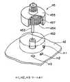
【図2】スイブルランプの縦断面図である。
【図3】スイブルランプの内部構造の分解斜視図である。
【図4】アクチュエータの部分分解斜視図である。
【図5】アクチュエータの縦断面図である。
【図6】ブラシレスモータの一部の拡大斜視図である。
【図7】AFSの回路構成を示すブロック回路図である。
【図8】アクチュエータの回路構成を示す回路図である。
【図9】操舵角度と偏向角度及び最大偏向角度の相関を示す特性図である。
【図10】第1の実施形態の動作のフローチャートである。
【図11】第2の実施形態における車速と最大偏向角度の相関を示す特性図である。
【図12】第2の実施形態の動作のフローチャートである。
【図13】第2の実施形態における車速と最大偏向角度の相関を示す特性図である。
【符号の説明】
1 センサ
2 ECU
3 前照灯
3L,3R スイブル式灯具
4 アクチュエータ
5 点灯回路
11 操舵角センサ
12 車速センサ
41 ケース
42 プリント基板
43 制御回路(電子部品)
44 回転出力軸
45 ブラシレスモータ
46 減速歯車機構
47 コネクタ
48 ポテンショメータ
49 可動接点機構
201 メインCPU
431 サブCPU
434 モータドライブ回路
434 スイッチングマトリクス回路
434 出力回路
H1,H2,H3 ホール素子[0001]
BACKGROUND OF THE INVENTION
The present invention relates to a lighting device for a vehicle such as an automobile, and more particularly to a lamp deflection angle control means for changing the irradiation direction of lamp light in accordance with a traveling situation, such as an adaptive lighting system (hereinafter referred to as AFS (Adaptive Front-lighting System)). The vehicle illumination device is provided with a vehicle illumination device that can set an appropriate irradiation direction corresponding to a change in vehicle speed.
[0002]
[Prior art]
As shown in the conceptual diagram of FIG. 1, the AFS proposed for improving the driving safety of a vehicle uses information indicating the steering angle of the steering wheel SW of the vehicle, the speed of the vehicle, and other driving conditions of the
[0003]
[Problems to be solved by the invention]
Through In this type of AFS, when driving at low speedArea near the front of the vehicle IsSo that the driver can see the previous area It is preferable to illuminate, and when driving at high speedSo that the driver can see the front-and-rear area, which is a considerable distance away in front of the vehicle Illumination is preferred, but with conventional AFS, the direction of illuminationIs the maximum deflectable angle No particular consideration is given to the maximum deflection angle. For example, the maximum deflection angle of the headlamp during both low-speed driving and high-speed drivingHaichi It is defined justice. for that reason,The area just before the direction of travel of the vehicle when driving at a low speed Properly lightingTherefore, the maximum deflection angle is increased so that the irradiation direction can be changed greatly. When set, when driving at high speedThe irradiation direction has changed too much In the direction of travelThere may be a situation that illuminates a region that is greatly deviated left and right from the far-field region (because the amount of change in the left-right direction of the illumination region increases with distance even at the same deflection angle) Proper illumination by AFS cannot be performed. Especially when driving at high speedsIf the direction of illumination changes significantly when driving on a gentle curve, the lighting in the far-end area in the traveling direction of the vehicle will be insufficient. This is a problem in terms of traffic safety. Conversely, to ensure proper lighting during high-speed drivingReduce maximum deflection angle to suppress changes in irradiation direction When set, curve roads when driving at low speeds, Especially on roads that change course significantly, such as intersections, the direction of irradiation will be insufficient, The previous area cannot be properly illuminated.
[0004]
Also, if the AFS operates when the steering wheel is turned over when the vehicle is slow enough to slow down or stop, especially when the vehicle is parked in the parking lot or in the garage, Is greatly deflected left and right, it becomes impossible to illuminate the area immediately in the straight direction of the own vehicle, and an unfavorable situation arises in terms of safety confirmation. In addition, when the lighting direction of the headlamp is greatly deflected when the vehicle is close to the vehicle in this way, it can be annoying for the passengers. But it is not preferable.
[0005]
An object of the present invention is to provide a vehicular illumination device that performs appropriate illumination following the vehicle speed.
[0006]
[Means for Solving the Problems]
The present invention provides a vehicle lighting device that includes a steering angle sensor that detects a steering direction of a vehicle, and includes a lamp deflection angle control unit that changes and controls a deflection angle of a lamp irradiation direction based on an output of the steering angle sensor. The vehicle includes a vehicle speed sensor for detecting the traveling speed of the vehicle, and the lamp deflection angle control means is configured to control the maximum deflection angle of the lamp deflection angle based on the vehicle speed detected by the vehicle speed sensor. When the vehicle is close to stopping, the maximum deflection angle is set to 0 °, and the speed is increased more than that.First The maximum deflection angle is set to the maximum angle at a predetermined speed.First When traveling at a speed above the specified speedUntil a predetermined maximum deflection angle is reached at a higher second predetermined speed The maximum deflection angle is gradually reduced as the vehicle speed increases. Alternatively, the ramp deflection angle control means sets the maximum deflection angle to 0 ° when the vehicle is close to a stop, increases the speed further, andFirst The maximum deflection angle is increased as the vehicle speed is increased during the transient running state until the predetermined speed is reached,First When traveling at a speed above the specified speedUntil a predetermined maximum deflection angle is reached at a higher second predetermined speed The maximum deflection angle is gradually reduced as the vehicle speed increases.
[0007]
According to the present invention, when the vehicle is in a traveling state close to a stop, the maximum deflection angle of the ramp is set to 0 °, so that the vehicle is slowly driven, stopped or parked, and further in a garage storage state. The illumination direction of the lamp will be fixed toward the vehicle's straight direction, and the area near the car will be illuminated in a stable state so that it will not dazzle cars or pedestrians that pass nearby. There is no feeling that the direction of irradiation is greatly deflected. In addition, when the vehicle is traveling at a speed close to high speed, the maximum deflection angle is suppressed as the vehicle speed increases, so that the ramp deflection angle is controlled within an angular range close to the straight direction of the vehicle. Regardless of the situation, it is possible to illuminate a straight-adjacent region that is a considerable distance ahead in the direction of travel, and the deflection angle of the lamp is prevented from swinging left and right. Further, when the speed is gradually reduced, the restriction on the maximum deflection angle is relaxed, so that it is possible to properly illuminate the area immediately before the traveling direction on the curved road. Furthermore, since the maximum deflection angle signal is limited as the vehicle speed decreases during the transitional traveling state between the stopped state and the traveling traveling state, the change in the maximum deflection angle between the stationary state and the traveling traveling state continues. Therefore, it is possible to avoid a sudden change in the direction of lamp irradiation when the vehicle is stopped or starting, and there is no concern about the occupant.
[0008]
DETAILED DESCRIPTION OF THE INVENTION
Next, embodiments of the present invention will be described with reference to the drawings. FIG. 2 is a longitudinal sectional view of the
[0009]
4 is an exploded perspective view of the main part of the actuator 4, and FIG. 5 is a longitudinal sectional view of the assembled state. The
[0010]
The
[0011]
The
[0012]
The
[0013]
The
[0014]
The
[0015]
FIG. 7 is a block circuit diagram showing an electric circuit configuration of the
[0016]
In addition, the
[0017]
FIG. 8 is a circuit diagram schematically showing the
[0018]
According to the above configuration, as shown in FIG. 1, the detection information of the steering angle of the steering wheel SW of the automobile is output from the steering angle sensor 11 disposed in the automobile, and the speed information of the automobile is outputted from the
[0019]
By such a deflection operation of the
[0020]
The
[0021]
The
[0022]
FIG. 10 is a flowchart for explaining an algorithm for setting the maximum deflection angle DM in the
[0023]
On the other hand, when it is determined in step S103 that the vehicle is in a traveling state at 5 Km / h or more, a maximum deflection angle DM is output such that the maximum deflection angle decreases linearly or quadratically in inverse proportion to the vehicle speed. Here, a function f (DS) having the angle of the steering angle signal DS as a variable is set (S107). The function f (DS) in this embodiment is a function of the maximum deflection angle DM having a characteristic in which the maximum deflection angle decreases linearly in the range from the characteristic A to the characteristic B in FIG. 9 as the vehicle speed increases. When a signal is output and the speed becomes high to some extent, the maximum deflection angle is fixed to the B characteristic.
[0024]
As described above, when the maximum deflection angle DM is set based on the vehicle speed and the deflection angle signal DS including the maximum deflection angle DM as information is output from the
[0025]
In this configuration, when the vehicle is stopped (
[0026]
On the other hand, when the vehicle is in a traveling state (from 5 km / h), the value of the maximum deflection angle DM gradually decreases as the vehicle speed increases. Therefore, when the steering wheel SW is rotated by a predetermined angle, the maximum deflection angle of the
[0027]
FIG. 12 is a flowchart for explaining an algorithm for controlling the maximum deflection angle DM in the
[0028]
In the second embodiment, the control of the maximum deflection angle DM in the stopped state and the traveling state is the same as that in the first embodiment as shown in steps S101 to S107. That is, when the vehicle is stopped (
[0029]
Further, in the second embodiment, in step S113, when the vehicle is in a transient running state (5 to 30 Km / h) based on the vehicle speed Vx, the maximum deflection angle DM is set by the second function f2 (DS) based on the deflection angle signal DS. (S115). Here, the value of the maximum deflection angle DM is gradually reduced as the vehicle speed decreases, contrary to the case of the traveling traveling state. This is for maintaining the continuity of the maximum deflection angle DM between the stop state and the traveling state described above, and the maximum of the
[0030]
Here, in the second embodiment, the maximum deflection angle is changed in a quadratic function in the transient running state, but it may be changed linearly. In each of the above embodiments, the maximum deflection angle is linearly changed in the traveling state, but may be changed in a quadratic function. Alternatively, in any case, it may be changed step by step in a minute width unit.
[0031]
In the above embodiment, an example of AFS using a headlamp in which a fixed lamp and a swivel lamp are integrally formed is shown as a swivel lamp. However, the swivel lamp is configured as a single independent lamp, and this is supported. It is also possible to configure a swivel-type lamp in combination with a headlamp composed of a fixed lamp as a lamp.
[0032]
【The invention's effect】
As described above, the present invention sets the maximum deflection angle of the ramp to 0 when the vehicle is in a driving state close to a stop, so that the vehicle is slowed down, stopped or parked, or even in a garage. When the vehicle is stopped, the direction of the lamp is fixed in the direction of the vehicle.Just before There is no dazzling of cars and pedestrians who illuminate the area in a stable state, and the headlight illumination direction is greatly deflected, so that it does not feel annoying. Vehicle on the other handUntil the second speed reaches the second predetermined speed at or above the first predetermined speed. When runningWhile maintaining the illumination deflection control function by AFS, As the vehicle speed increasesThe maximum deflection angle is reduced until a predetermined maximum deflection angle is reached, and at higher speeds it is fixed at the predetermined maximum deflection angle, The deflection angle of the ramp is controlled within an angle range close to the straight direction of the vehicle, and it is separated by a considerable distance ahead of the traveling direction regardless of the steering status of the vehicleForefield area The lamp deflection angle can bebig Swaying from side to side is suppressed. Further, when the speed is gradually reduced, the restriction on the maximum deflection angle is relaxed, so that it is possible to properly illuminate the area immediately before the traveling direction on the curved road. In addition, when the vehicle is in a transient state, the maximum deflection as the vehicle speed decreases.Angle is Because it is restricted, the continuity of the change in the maximum deflection angle between the stopping state and the traveling state can be maintained, and it is possible to avoid the rapid change in the lamp irradiation direction when stopping or starting, etc. There is no such thing.
[Brief description of the drawings]
FIG. 1 is a diagram illustrating a conceptual configuration of an AFS.
FIG. 2 is a longitudinal sectional view of a swivel lamp.
FIG. 3 is an exploded perspective view of the internal structure of the swivel lamp.
FIG. 4 is a partially exploded perspective view of an actuator.
FIG. 5 is a longitudinal sectional view of an actuator.
FIG. 6 is an enlarged perspective view of a part of the brushless motor.
FIG. 7 is a block circuit diagram showing a circuit configuration of an AFS.
FIG. 8 is a circuit diagram showing a circuit configuration of an actuator.
FIG. 9 is a characteristic diagram showing a correlation between a steering angle, a deflection angle, and a maximum deflection angle.
FIG. 10 is a flowchart of the operation of the first embodiment.
FIG. 11 is a characteristic diagram showing the correlation between the vehicle speed and the maximum deflection angle in the second embodiment.
FIG. 12 is a flowchart of the operation of the second embodiment.
FIG. 13 is a characteristic diagram showing the correlation between the vehicle speed and the maximum deflection angle in the second embodiment.
[Explanation of symbols]
1 Sensor
2 ECU
3 headlights
3L, 3R swivel lamp
4 Actuator
5 lighting circuit
11 Steering angle sensor
12 Vehicle speed sensor
41 cases
42 Printed circuit board
43 Control circuit (electronic parts)
44 Rotation output shaft
45 Brushless motor
46 Reduction gear mechanism
47 connector
48 Potentiometer
49 Movable contact mechanism
201 Main CPU
431 Sub CPU
434 Motor drive circuit
434 switching matrix circuit
434 output circuit
H1, H2, H3 Hall element
Claims (2)
Translated fromJapanesePriority Applications (3)
| Application Number | Priority Date | Filing Date | Title |
|---|---|---|---|
| JP2001135901AJP4140751B2 (en) | 2001-05-07 | 2001-05-07 | Vehicle lighting device |
| US10/138,285US6726349B2 (en) | 2001-05-07 | 2002-05-03 | Vehicle lighting apparatus |
| DE10220373.3ADE10220373B4 (en) | 2001-05-07 | 2002-05-07 | The vehicle lighting device |
Applications Claiming Priority (1)
| Application Number | Priority Date | Filing Date | Title |
|---|---|---|---|
| JP2001135901AJP4140751B2 (en) | 2001-05-07 | 2001-05-07 | Vehicle lighting device |
Publications (2)
| Publication Number | Publication Date |
|---|---|
| JP2002326538A JP2002326538A (en) | 2002-11-12 |
| JP4140751B2true JP4140751B2 (en) | 2008-08-27 |
Family
ID=18983286
Family Applications (1)
| Application Number | Title | Priority Date | Filing Date |
|---|---|---|---|
| JP2001135901AExpired - Fee RelatedJP4140751B2 (en) | 2001-05-07 | 2001-05-07 | Vehicle lighting device |
Country Status (3)
| Country | Link |
|---|---|
| US (1) | US6726349B2 (en) |
| JP (1) | JP4140751B2 (en) |
| DE (1) | DE10220373B4 (en) |
Families Citing this family (16)
| Publication number | Priority date | Publication date | Assignee | Title |
|---|---|---|---|---|
| JP2003112568A (en)* | 2001-10-04 | 2003-04-15 | Koito Mfg Co Ltd | Lighting device for vehicle |
| US20040263346A1 (en)* | 2003-06-27 | 2004-12-30 | Guide Corporation, A Delaware Corporation | Solid state adaptive forward lighting system |
| DE10329873A1 (en)* | 2003-07-02 | 2005-01-20 | Volkswagen Ag | Vehicle headlight, comprises at least two sensors which are formed for a swivel angular measurement at different measurement angles |
| JP4199063B2 (en)* | 2003-07-10 | 2008-12-17 | 株式会社小糸製作所 | Vehicle lighting device |
| JP4321450B2 (en)* | 2004-07-26 | 2009-08-26 | 株式会社デンソー | Visual recognition support device |
| JP4520282B2 (en)* | 2004-10-28 | 2010-08-04 | アスモ株式会社 | Rotating drive device and vehicle headlamp device |
| CN100425473C (en)* | 2004-11-01 | 2008-10-15 | 吴胜隆 | Automobile auxiliary lamp capable of free rotation |
| DE102005013600A1 (en) | 2005-03-24 | 2006-10-19 | Hella Kgaa Hueck & Co. | Device and method for controlling the swivel angle of a cornering headlight for a motor vehicle as a function of the curve radius and the speed |
| JP2007045256A (en)* | 2005-08-08 | 2007-02-22 | Ichikoh Ind Ltd | Vehicle headlamp device |
| JP4534901B2 (en)* | 2005-08-11 | 2010-09-01 | 日産自動車株式会社 | Headlamp optical axis control device and headlamp optical axis control method |
| EP1757486B1 (en)* | 2005-08-26 | 2014-04-30 | Nissan Motor Co., Ltd. | Device and method for controlling vehicle headlamps |
| US20080055918A1 (en)* | 2006-08-31 | 2008-03-06 | Anthony Peter Mascadri | Vehicular lamp assembly having multiple moveable reflectors |
| DE102007056118B4 (en)* | 2006-12-08 | 2018-01-18 | Johnson Electric Switzerland Ag | Device for pivoting a light beam emitted by a headlight |
| KR101438814B1 (en)* | 2007-03-16 | 2014-09-17 | 엘지이노텍 주식회사 | Headlamp control device and method |
| JP4683668B2 (en)* | 2009-02-06 | 2011-05-18 | 株式会社小糸製作所 | Actuator |
| CN102658791A (en)* | 2012-05-25 | 2012-09-12 | 北京经纬恒润科技有限公司 | Automatic dimming system for automotive headlamps |
Family Cites Families (12)
| Publication number | Priority date | Publication date | Assignee | Title |
|---|---|---|---|---|
| US4663696A (en)* | 1985-01-31 | 1987-05-05 | Koito Siesakusho Co., Ltd. | Dual purpose lamp assembly for use, for example, as a combined fog and cornering lamp on a motor vehicle |
| FR2587947B1 (en)* | 1985-09-30 | 1990-06-29 | Koito Mfg Co Ltd | CORNER LIGHTING SYSTEM FOR VEHICLE |
| JP3546600B2 (en)* | 1995-09-07 | 2004-07-28 | トヨタ自動車株式会社 | Light distribution control device for headlamp |
| JP3622808B2 (en)* | 1996-06-03 | 2005-02-23 | 本田技研工業株式会社 | Vehicle headlamp device |
| JPH10166934A (en)* | 1996-12-13 | 1998-06-23 | Koito Mfg Co Ltd | Lamp device for vehicle |
| JPH10175478A (en) | 1996-12-18 | 1998-06-30 | Koito Mfg Co Ltd | Lighting fixture device for vehicle |
| JPH10203232A (en)* | 1997-01-29 | 1998-08-04 | Honda Motor Co Ltd | Headlight device for vehicles |
| US5781105A (en) | 1997-04-09 | 1998-07-14 | Ford Motor Company | Light management system for a vehicle |
| JP3839609B2 (en) | 1999-02-22 | 2006-11-01 | 株式会社小糸製作所 | Vehicle lamp device |
| JP3760693B2 (en) | 1999-10-08 | 2006-03-29 | 日産自動車株式会社 | Vehicle lighting device |
| DE19950505A1 (en)* | 1999-10-20 | 2001-04-26 | Porsche Ag | Device for controlling the light distribution of a headlight arrangement of a vehicle |
| JP2001213227A (en)* | 2000-02-04 | 2001-08-07 | Koito Mfg Co Ltd | Lighting system for vehicle |
- 2001
- 2001-05-07JPJP2001135901Apatent/JP4140751B2/ennot_activeExpired - Fee Related
- 2002
- 2002-05-03USUS10/138,285patent/US6726349B2/ennot_activeExpired - Fee Related
- 2002-05-07DEDE10220373.3Apatent/DE10220373B4/ennot_activeExpired - Fee Related
Also Published As
| Publication number | Publication date |
|---|---|
| US20020163795A1 (en) | 2002-11-07 |
| DE10220373A1 (en) | 2002-11-21 |
| JP2002326538A (en) | 2002-11-12 |
| US6726349B2 (en) | 2004-04-27 |
| DE10220373B4 (en) | 2017-10-05 |
Similar Documents
| Publication | Publication Date | Title |
|---|---|---|
| JP3687741B2 (en) | Vehicle lighting device | |
| JP4140751B2 (en) | Vehicle lighting device | |
| JP4132880B2 (en) | Vehicle lighting device | |
| JP3643315B2 (en) | Vehicle lighting device | |
| US6634773B2 (en) | Vehicle lighting apparatus | |
| JP4130345B2 (en) | Vehicle headlamp device | |
| KR100512338B1 (en) | Vehicle headlamp apparatus and method of setting optical axis position thereof | |
| JP3996038B2 (en) | Vehicle headlamp device | |
| US7057504B2 (en) | Vehicle headlamp apparatus | |
| JP4094389B2 (en) | Vehicle headlamp device | |
| JP2002326534A (en) | Lighting system for vehicle | |
| JP2004222463A (en) | Brushless motor | |
| KR20090014547A (en) | Bending light system for a motor vehicle | |
| JP4130353B2 (en) | Vehicle headlamp device | |
| KR100301405B1 (en) | Beam width controller of a vehicle head lamp | |
| JP2005319884A (en) | Lighting device for vehicle | |
| KR19980042746U (en) | Headlight Projection Direction Adjuster | |
| KR19980085490A (en) | Irradiation angle adjusting device of headlight according to driving direction of vehicle | |
| JP2008105625A (en) | Vehicle lighting device | |
| KR20000006552U (en) | Automotive headlight structure with adjustable angle |
Legal Events
| Date | Code | Title | Description |
|---|---|---|---|
| A977 | Report on retrieval | Free format text:JAPANESE INTERMEDIATE CODE: A971007 Effective date:20041022 | |
| A131 | Notification of reasons for refusal | Free format text:JAPANESE INTERMEDIATE CODE: A131 Effective date:20041109 | |
| A521 | Written amendment | Free format text:JAPANESE INTERMEDIATE CODE: A523 Effective date:20041227 | |
| A02 | Decision of refusal | Free format text:JAPANESE INTERMEDIATE CODE: A02 Effective date:20050531 | |
| A521 | Written amendment | Free format text:JAPANESE INTERMEDIATE CODE: A523 Effective date:20050727 | |
| A521 | Written amendment | Free format text:JAPANESE INTERMEDIATE CODE: A523 Effective date:20080428 | |
| A01 | Written decision to grant a patent or to grant a registration (utility model) | Free format text:JAPANESE INTERMEDIATE CODE: A01 | |
| A61 | First payment of annual fees (during grant procedure) | Free format text:JAPANESE INTERMEDIATE CODE: A61 Effective date:20080604 | |
| FPAY | Renewal fee payment (event date is renewal date of database) | Free format text:PAYMENT UNTIL: 20110620 Year of fee payment:3 | |
| R150 | Certificate of patent or registration of utility model | Free format text:JAPANESE INTERMEDIATE CODE: R150 | |
| FPAY | Renewal fee payment (event date is renewal date of database) | Free format text:PAYMENT UNTIL: 20120620 Year of fee payment:4 | |
| FPAY | Renewal fee payment (event date is renewal date of database) | Free format text:PAYMENT UNTIL: 20120620 Year of fee payment:4 | |
| FPAY | Renewal fee payment (event date is renewal date of database) | Free format text:PAYMENT UNTIL: 20130620 Year of fee payment:5 | |
| LAPS | Cancellation because of no payment of annual fees |