JP4140691B2 - Operating method of redox flow battery - Google Patents
Operating method of redox flow batteryDownload PDFInfo
- Publication number
- JP4140691B2 JP4140691B2JP2002120165AJP2002120165AJP4140691B2JP 4140691 B2JP4140691 B2JP 4140691B2JP 2002120165 AJP2002120165 AJP 2002120165AJP 2002120165 AJP2002120165 AJP 2002120165AJP 4140691 B2JP4140691 B2JP 4140691B2
- Authority
- JP
- Japan
- Prior art keywords
- cell
- cells
- auxiliary
- charging
- redox flow
- Prior art date
- Legal status (The legal status is an assumption and is not a legal conclusion. Google has not performed a legal analysis and makes no representation as to the accuracy of the status listed.)
- Expired - Fee Related
Links
Images


Classifications
- H—ELECTRICITY
- H01—ELECTRIC ELEMENTS
- H01M—PROCESSES OR MEANS, e.g. BATTERIES, FOR THE DIRECT CONVERSION OF CHEMICAL ENERGY INTO ELECTRICAL ENERGY
- H01M8/00—Fuel cells; Manufacture thereof
- H01M8/24—Grouping of fuel cells, e.g. stacking of fuel cells
- H01M8/2455—Grouping of fuel cells, e.g. stacking of fuel cells with liquid, solid or electrolyte-charged reactants
- H—ELECTRICITY
- H01—ELECTRIC ELEMENTS
- H01M—PROCESSES OR MEANS, e.g. BATTERIES, FOR THE DIRECT CONVERSION OF CHEMICAL ENERGY INTO ELECTRICAL ENERGY
- H01M8/00—Fuel cells; Manufacture thereof
- H01M8/04—Auxiliary arrangements, e.g. for control of pressure or for circulation of fluids
- H01M8/04082—Arrangements for control of reactant parameters, e.g. pressure or concentration
- H01M8/04186—Arrangements for control of reactant parameters, e.g. pressure or concentration of liquid-charged or electrolyte-charged reactants
- H—ELECTRICITY
- H01—ELECTRIC ELEMENTS
- H01M—PROCESSES OR MEANS, e.g. BATTERIES, FOR THE DIRECT CONVERSION OF CHEMICAL ENERGY INTO ELECTRICAL ENERGY
- H01M8/00—Fuel cells; Manufacture thereof
- H01M8/18—Regenerative fuel cells, e.g. redox flow batteries or secondary fuel cells
- H01M8/184—Regeneration by electrochemical means
- H01M8/188—Regeneration by electrochemical means by recharging of redox couples containing fluids; Redox flow type batteries
- H—ELECTRICITY
- H01—ELECTRIC ELEMENTS
- H01M—PROCESSES OR MEANS, e.g. BATTERIES, FOR THE DIRECT CONVERSION OF CHEMICAL ENERGY INTO ELECTRICAL ENERGY
- H01M8/00—Fuel cells; Manufacture thereof
- H01M8/20—Indirect fuel cells, e.g. fuel cells with redox couple being irreversible
- H—ELECTRICITY
- H01—ELECTRIC ELEMENTS
- H01M—PROCESSES OR MEANS, e.g. BATTERIES, FOR THE DIRECT CONVERSION OF CHEMICAL ENERGY INTO ELECTRICAL ENERGY
- H01M2250/00—Fuel cells for particular applications; Specific features of fuel cell system
- H01M2250/40—Combination of fuel cells with other energy production systems
- H—ELECTRICITY
- H01—ELECTRIC ELEMENTS
- H01M—PROCESSES OR MEANS, e.g. BATTERIES, FOR THE DIRECT CONVERSION OF CHEMICAL ENERGY INTO ELECTRICAL ENERGY
- H01M8/00—Fuel cells; Manufacture thereof
- H01M8/24—Grouping of fuel cells, e.g. stacking of fuel cells
- H01M8/249—Grouping of fuel cells, e.g. stacking of fuel cells comprising two or more groupings of fuel cells, e.g. modular assemblies
- Y—GENERAL TAGGING OF NEW TECHNOLOGICAL DEVELOPMENTS; GENERAL TAGGING OF CROSS-SECTIONAL TECHNOLOGIES SPANNING OVER SEVERAL SECTIONS OF THE IPC; TECHNICAL SUBJECTS COVERED BY FORMER USPC CROSS-REFERENCE ART COLLECTIONS [XRACs] AND DIGESTS
- Y02—TECHNOLOGIES OR APPLICATIONS FOR MITIGATION OR ADAPTATION AGAINST CLIMATE CHANGE
- Y02E—REDUCTION OF GREENHOUSE GAS [GHG] EMISSIONS, RELATED TO ENERGY GENERATION, TRANSMISSION OR DISTRIBUTION
- Y02E60/00—Enabling technologies; Technologies with a potential or indirect contribution to GHG emissions mitigation
- Y02E60/30—Hydrogen technology
- Y02E60/50—Fuel cells
Landscapes
- Life Sciences & Earth Sciences (AREA)
- Engineering & Computer Science (AREA)
- Manufacturing & Machinery (AREA)
- Sustainable Development (AREA)
- Sustainable Energy (AREA)
- Chemical & Material Sciences (AREA)
- Chemical Kinetics & Catalysis (AREA)
- Electrochemistry (AREA)
- General Chemical & Material Sciences (AREA)
- Fuel Cell (AREA)
Description
Translated fromJapanese【0001】
【発明の属する技術分野】
本発明は、レドックスフロー電池の運転方法に関するものである。特に、常時、充電状態を把握することができ、出力容量を安定させるのに最適なレドックスフロー電池の運転方法に関するものである。
【0002】
【従来の技術】
レドックスフロー電池は、従来、負荷平準化や瞬停対策用として利用されている。図3はレドックスフロー電池の動作原理を示す説明図である。この電池は、イオン交換膜からなる隔膜103で正極セル100Aと負極セル100Bとに分離されたセル100を具える。正極セル100Aと負極セル100Bの各々には正極電極104と負極電極105とを内蔵している。正極セル100Aには正極電解液を供給・排出するための正極用タンク101が導管106、107を介して接続されている。負極セル100Bにも負極電解液を導入・排出する負極用タンク102が同様に導管109、110を介して接続されている。各電解液にはバナジウムイオンなど原子価が変化するイオンの水溶液を用い、ポンプ108、111で循環させ、正負極電極104、105におけるイオンの価数変化反応に伴って充放電を行う。例えば、バナジウムイオンを含む電解液を用いた場合、セル内で充放電時に生じる反応は次のとおりである。
正極:V4+→V5++e-(充電) V4+←V5++e-(放電)
負極:V3++e-→V2+(充電) V3++e-←V2+(放電)
【0003】
図4は、上記の電池に用いるセルスタックの概略構成図である。通常、上記の電池には、複数のセルが積層されたサブスタック201を更に複数積層させたセルスタック200と呼ばれる構成が利用される。各セルは、隔膜103の両側にカーボンフェルト製の正極電極104および負極電極105を具える。そして、正極電極104と負極電極105の各々の外側には、セルフレーム210が配置される。セルフレーム210は、プラスチックカーボン製の双極板211と、その外周に形成されるフレーム枠212とを具える。
【0004】
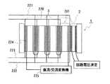
フレーム枠212には、マニホールドと呼ばれる複数の孔が形成されている。1枚のセルフレームには、例えば下辺に4つ、上辺に4つの合計8つのマニホールドが設けられ、下辺の2つが正極電解液供給用、残り2つが負極電解液供給用、上辺の2つが正極電解液排出用、残り2つが負極電解液排出用となっている。マニホールドは、多数のセルを積層することで電解液の流路を構成し、図3における導管106、107、109、110へとつながっている。そして、電解液は、サブスタック201ごとに供給排出される。図2に示すように、サブスタック201毎に正負極電解液の供給用パイプ220、221、排出用パイプ222、223が接続されている。
【0005】
上記サブスタック201間は銅板などの導電性板224で結線されており、電解液の供給用パイプ220、221、排出用パイプ222、223と異なる面に電気端子(図示せず)を具える。この電気端子を介してセルスタック200全体の結線は、通常、直流/交流変換機(インバータ)225に接続されている。
【0006】
このようなレドックスフロー電池において負荷平準化用途では、従来、予め定められた通電電圧の上限値及び下限値によって、充電の停止や放電の停止を行っており、いずれの停止も通電電圧(セルに通電している状態での電圧)によって決められている。また、従来、セル内の電解液の充電状態(充電率)は、回路電圧(セルに通電していない状態での電圧)によって把握することが行われている。
【0007】
【発明が解決しようとする課題】
しかし、従来のレドックスフロー電池には、以下の問題があった。
(1) 通電電圧により充電や放電の停止を決めると、充電率にばらつきが生じることがある。
運転条件は、電池の劣化程度によって電池抵抗が異なることや温度などの環境などで変動するものであり、例えば、一般に温度が高いほど充放電がよく行える。そのため、通電電圧により充電の停止や放電の停止を決めると、運転条件によって充電停止時の充電率や放電停止時の充電率がばらつく、即ち、出力容量(KWH)がばらつく恐れがある。
【0008】
(2) 従来のレドックスフロー電池では、充電率を常時把握することが困難である。
回路電圧を測定するためには、通電を停止する必要がある。従って、従来のように回路電圧により充電状態(充電率)を常時把握しようとすると、通電を停止し続けることになり、現実的でない。また、近年、出力容量を安定化させるために風力発電や太陽光発電などにレドックスフロー電池を組み合わせることが知られている。このとき、電解液の充電率を把握して充電率を適宜変更させないと、十分に充放電できない恐れがある。そのため、充電率を常時把握できることが望まれている。
【0009】
そこで、本発明の主目的は、充電状態をより確実に把握することができ、出力容量を安定させることが可能なレドックスフロー電池の運転方法を提供することにある。
【0010】
【課題を解決するための手段】
本発明は、セルスタック内に回路電圧を監視するためのモニタ用の補助セルを一体に具えることで上記の目的を達成する。
【0011】
即ち、本発明は、複数のセルからなるセルスタックを具えるレドックスフロー電池の運転方法である。正負極の電解液が供給・排出されるセルスタック内の少なくとも一部のセルで常時は直流/交流変換機に接続されないセルを電解液の充電率測定に用いる補助セルとする。セルスタック内のセルにおいて常時は直流/交流変換機に接続される他のセルを充放電に用いる主セルとする。この主セルの通電を停止させることなく、上記補助セルを用いて回路電圧を測定する。そして、この補助セルから得られる回路電圧に応じて主セルの充電の停止及び放電の停止の少なくとも一方を行う。
【0012】
本発明は、電解液を共通するように構成されているセルスタック内のうち、一部のセルを補助セルとして充電率測定に用いる。即ち、この補助セルは、セルスタック内に常時は電解液を流通させているだけで充放電を行わないセルとなる。その他のセルは、充放電に用いられるセル(主セル)となる。そして、主セルの充電や放電の停止は、補助セルから測定した回路電圧が一定の値に達したときに行うとよい。上記補助セルを具えることで、回路電圧を測定する際、従来のように通電を停止させることなく、ほぼ常時、回路電圧を測定することができる。また、回路電圧を充電の停止信号や放電の停止信号に用いると、ほぼ同じ充電状態の範囲で電池を使用することができるため、安定した出力容量を確保することができる。
【0013】
ここで、従来のレドックスフロー電池において、充放電を行うためのセルスタックと別にモニタ用のセルスタックを設置することが考えられる。しかし、モニタ用のセルスタックを別途設けた場合、設備が大きくなるだけでなく、コストアップにもつながる。これに対し、本発明では、充放電を行うためのセルスタックの一部を補助セルとした一体構造であるため、特別な設備などを必要とせず、生産性に優れるだけでなく、設備の縮小、コストの低減が可能である。
【0014】
また、本発明運転方法は、上記と同様にセルスタック内の少なくとも一部のセルで常時は直流/交流変換機に接続されないセルを補助セルとし、補助セルから得られる回路電圧に応じて補助セルを充電又は放電して電解液の充電率を変化させることを特徴とする。
【0015】
上述の発明は、補助セルから測定した回路電圧により主セルの充電の停止や放電の停止を制御するものであり、補助セルをほぼ常時回路電圧の測定に用いる。この発明は、回路電圧の測定に加え、補助セルから測定した回路電圧の値が一定の値である場合、モニタを停止し、補助セルを一時的に充放電に用いる。このような本発明運転方法は、風力発電や太陽光発電などとレドックスフロー電池を組み合わせる場合や、需給制御のような出力容量が不安定となるような電池運転を行う場合などに最適である。このとき、通常充放電を行う主セルの充電率を補助セルにより確実に把握できると共に、主セルの充電率が下がり過ぎたり上がり過ぎた場合であっても、補助セルで充電や放電させることで充放電用の主セルが放電や充電を続けることができ、出力容量を安定させることが可能である。
【0016】
なお、補助セルで充放電を行う場合は、別途電源を取り付けてから行うとよい。
【0017】
このような本発明運転方法には、以下のようなセルスタックを用いることが好適である。即ち、このセルスタックは、複数のセルを具えるレドックスフロー電池セルスタックであって、以下の主セルと補助セルとを一体に具える。
正負極の電解液を供給・排出させると共に直流/交流変換機に接続される主セル。
前記主セルと電解液を共通するように接続されたセルで常時は直流/交流変換機に接続されない電解液の充電率測定用の補助セル。
【0018】
補助セルは、主セルを構成するサブスタックと同様の構成とすればよく、複数のセルを積層して形成するとよい。このとき、補助セルは、サブスタックを構成するセルの数よりも少ない方が設備を縮小でき、またコストを低減できるため、好ましい。
【0019】
【発明の実施の形態】
以下、本発明の実施の形態を説明する。
(試験例1)
AC170KW×8時間のレドックスフロー電池を作製し、温度を変化させて電池容量の変化を調べてみた。試験では、図3、4に示すレドックスフロー電池を組み立た。試料No.1-1は、図1に示すようにセル(図示せず)を25枚積層させたサブスタック201を4組(主セル3)、同様のセル1枚からなる補助セル2を1組、計5組のセル群からなるセルスタック1を用いた電池とした。試料No.1-2は、図2に示すようにサブスタック201:4組からなり、補助セルを有しない(主セルのみからなる)セルスタック200を用いた電池とした。試験における運転条件を以下に示す。また、表1に試験結果を示す。
【0020】
試料No.1-1:補助セルにより回路電圧を常時測定し、回路電圧により主セルの充電の停止、放電の停止を制御する。回路電圧1.46V/セルまで充電、回路電圧1.33V/セルまで放電を行う。
試料No.1-2:通電電圧を常時測定し、通電電圧により主セルの充電の停止、放電の停止を制御する。充電電圧1.55V/セル、放電電圧1V/セルとして運転を行う。
【0021】
【表1】
表1に示すようにいずれの試料も、比較的高温である35℃では、放電出力容量は定格の8時間であった。しかし、比較的低温である25℃では、通電電圧により主セルの充電や放電の停止を行った試料No.1-2は定格を下回る容量しか得られなかった。これに対し、回路電圧により主セルの充電や放電の停止を行った試料No.1-1は、定格である8時間の放電出力容量が得られた。
【0023】
この試験の結果から、補助セルにより回路電圧を測定し、回路電圧により主セルの充電や放電の停止を制御する本発明は、温度などに影響されることなく出力容量を安定できることがわかる。また、補助セルをセルスタックに一体に具えて、この補助セルにより回路電圧を測定するため、測定の際に主セルの通電を停止する必要がない。
【0024】
(試験例2)
AC170KW×6時間のレドックスフロー電池を作製し、主セルの充電率が下がった際、補助セルを充電させてみた。電池の基本的構成は、試験例1で用いた試料No.1-1のレドックスフロー電池と同様とした。試験は、補助セルにより回路電圧を測定しておき、回路電圧が1.35V/セルになったら、補助セルに直流電源を別途取り付けて、通電開始した。
【0025】
試験の結果、定電流運転で補助セルによって約100KWh充電することで、低下していた主セルの充電率を上げることができ、補助セルで充電した分、放電を続けることができた。そして、出力容量は、ほぼ6.5時間であった。比較として、回路電圧が1.35V/セルになっても補助セルを充電させなかったものは、出力容量が6時間で放電が終了した。
【0026】
この試験から、補助セルは、回路電圧を常時測定できるだけでなく、必要に応じて主セルの充電に用いてもよいことがわかる。また、補助セルを充電に用いることで、出力容量を増加することができる。
【0027】
(試験例3)
試験例2で作製したレドックスフロー電池(AC170KW×6時間)を風力発電機に組み合わせて、主セルの充電率が下がった際、風力発電機と電池を合わせた総合出力を下げてみた。試験は、補助セルにより回路電圧を測定しておき、回路電圧が1.37V/セルになったら総合出力を下げ、回路電圧が1.35V/セルになるまで運転を行った。以下に、風力発電機の仕様を示す。
【0028】
(風力発電機の仕様)
型式:誘電発電機
定格出力:275kW
定格電圧:400V
定格回転数:1500rpm
【0029】
試験の結果、総合出力を下げたことで主セルの充電率を上げることができ、放電を続けることができた。そして、出力容量は、ほぼ1120kWhであった。比較として、回路電圧が1.37V/セルになっても総合出力を下げなかった場合は、出力容量は1020kWhであった。
【0030】
実施例2及び3では、主セルの充電率を上げる場合について調べたが、主セルの充電率が上がり過ぎて充電ができない場合は、逆に補助セルを放電させたり、総合出力を上げることで充電率を下げることができた。
【0031】
【発明の効果】
以上、説明したように補助セルをセルスタックに一体に具えることで、通電を停止することなく回路電圧をほぼ常時測定することができるという優れた効果を奏し得る。また、本発明運転方法は、測定で得られた回路電圧によって主セルの充電の停止や放電の停止を制御することで、出力容量をより安定させることができる。従って、本発明運転方法は、風力発電や需要制御のような不規則な運転であっても、出力容量の安定化を実現する。
【図面の簡単な説明】
【図1】本発明レドックスフロー電池の運転方法に用いるセルスタックの模式図である。
【図2】従来のセルスタックの模式図である。
【図3】レドックスフロー電池の動作原理を示す説明図である。
【図4】レドックスフロー電池に用いるセルスタックの概略構成図である。
【符号の説明】
1 セルスタック 2 補助セル 3 主セル
100 セル 100A 正極セル 100B 負極セル 101 正極用タンク
102 負極用タンク 103 隔膜 104 正極電極 104 正負極電極
105 負極電極 106 導管 108 ポンプ 109 導管
200 セルスタック 201 サブスタック
210 セルフレーム 211 双極板 212 フレーム枠
220、221 供給用パイプ 222、223 排出用パイプ 224 導電性板
225 直流/交流変換機[0001]
BACKGROUND OF THE INVENTION
The present invention relatesto the operationhow the redox flow battery. In particular, always able to grasp the state of charge, but aboutthe operationhow the optimum redox flow battery output capacitance to stabilize.
[0002]
[Prior art]
Redox flow batteries are conventionally used for load leveling and for instantaneous power failure countermeasures. FIG. 3 is an explanatory diagram showing the operating principle of the redox flow battery. This battery includes a
The positiveelectrode: V 4+ → V 5+ + e - (charging) V 4+ ← V 5+ + e - ( discharge)
The negativeelectrode: V 3+ + e - → V 2+ (charging) V 3+ + e - ← V 2+ ( discharge)
[0003]
FIG. 4 is a schematic configuration diagram of a cell stack used in the above battery. Usually, the above-described battery uses a configuration called a
[0004]
The
[0005]
The
[0006]
In load leveling applications in such redox flow batteries, conventionally, charging and discharging are stopped according to predetermined upper and lower limit values of energization voltage. It is determined by the voltage during energization. Conventionally, the state of charge (charge rate) of the electrolyte in the cell has been grasped by the circuit voltage (voltage when the cell is not energized).
[0007]
[Problems to be solved by the invention]
However, the conventional redox flow battery has the following problems.
(1) If charging or discharging is stopped by the energization voltage, the charging rate may vary.
The operating conditions vary depending on the battery resistance and the environment such as temperature depending on the degree of deterioration of the battery. For example, generally, the higher the temperature, the better the charge / discharge. Therefore, if charging stop or discharging stop is determined by the energized voltage, the charging rate at the time of charging stop or the charging rate at the time of discharging stop varies depending on the operating conditions, that is, the output capacity (KWH) may vary.
[0008]
(2) With conventional redox flow batteries, it is difficult to keep track of the charging rate.
In order to measure the circuit voltage, it is necessary to stop energization. Therefore, if it is attempted to constantly grasp the state of charge (charging rate) by means of the circuit voltage as in the prior art, the energization will continue to be stopped, which is not practical. In recent years, it has been known to combine a redox flow battery with wind power generation or solar power generation in order to stabilize the output capacity. At this time, unless the charging rate of the electrolytic solution is grasped and the charging rate is appropriately changed, there is a possibility that sufficient charging / discharging cannot be performed. Therefore, it is desired that the charging rate can be always grasped.
[0009]
Therefore, the main object of the present invention is to providea drivinghow more reliably can be grasped, a redox flow battery capable of stabilizing the output capacitance charging status.
[0010]
[Means for Solving the Problems]
The present invention achieves the above object by integrally providing a monitoring auxiliary cell for monitoring the circuit voltage in the cell stack.
[0011]
That is, the present invention is a method for operating a redox flow battery including a cell stack composed of a plurality of cells. At least some of the cells in the cell stack to which positive and negative electrolyte solutions are supplied / discharged are cells that are not always connected to the DC / AC converter as auxiliary cells used for measuring the charge rate of the electrolyte solution.In the cells in the cell stack,other cells connected to theDC/AC converterare always set asmain cells used for charging / discharging. The circuit voltage is measured using the auxiliary cell without stopping energization of the main cell. Then, at least one of stopping charging and stopping discharging of themain cell is performed according to the circuit voltage obtained from the auxiliary cell.
[0012]
In the present invention, some of the cells in the cell stack configured to share the electrolyte solution are used as auxiliary cells for charge rate measurement. In other words, the auxiliary cell is a cell in which the electrolytic solution is always circulated in the cell stack and charging / discharging is not performed. The other cells are cells (main cells) used for charging / discharging. Then, the charging or discharging of the main cell is preferably stopped when the circuit voltage measured from the auxiliary cell reaches a certain value. By providing the auxiliary cell, when measuring the circuit voltage, the circuit voltage can be measured almost always without stopping energization as in the prior art. In addition, when the circuit voltage is used as a charge stop signal or a discharge stop signal, the battery can be used in a range of substantially the same charge state, so that a stable output capacity can be ensured.
[0013]
Here, in a conventional redox flow battery, it is conceivable to install a monitoring cell stack separately from a cell stack for charging and discharging. However, when a monitor cell stack is provided separately, not only the equipment becomes large, but also the cost increases. On the other hand, in the present invention, since it is an integrated structure in which a part of the cell stack for performing charging / discharging is an auxiliary cell, it does not require special equipment and is not only excellent in productivity but also reduced in equipment. Cost reduction is possible.
[0014]
In addition, the operation method of the present invention uses, as described above, at least some of the cells in the cell stack that are not always connected to the DC / AC converter as auxiliary cells, and the auxiliary cells according to the circuit voltage obtained from the auxiliary cells. Is charged or discharged to change the charging rate of the electrolyte.
[0015]
The above-described invention controls the stop of the charge and discharge of the main cell by the circuit voltage measured from the auxiliary cell, and the auxiliary cell is almost always used for measuring the circuit voltage. In this invention, in addition to the measurement of the circuit voltage, when the value of the circuit voltage measured from the auxiliary cell is a constant value, the monitoring is stopped and the auxiliary cell is temporarily used for charging and discharging. Such an operation method of the present invention is optimal when combining wind power generation, solar power generation, and the like with a redox flow battery, or when performing battery operation such as supply and demand control where output capacity becomes unstable. At this time, the charging rate of the main cell that performs normal charging / discharging can be reliably grasped by the auxiliary cell, and even if the charging rate of the main cell is too low or too high, the auxiliary cell can be charged or discharged. The main cell for charging / discharging can continue discharging and charging, and the output capacity can be stabilized.
[0016]
In addition, when charging / discharging with an auxiliary cell, it is good to carry out after attaching a power supply separately.
[0017]
In such an operation method of the present invention, the following cell stack is preferably used. In other words,this cell stack is a redox flow battery cell stack including a plurality of cells, and includes the following main cells and auxiliary cells.
A main cell that supplies and discharges positive and negative electrolytes and is connected to a DC / AC converter.
An auxiliary cell for measuring a charging rate of an electrolytic solution that is connected to the main cell so as to share the electrolytic solution and is not always connected to a DC / AC converter.
[0018]
The auxiliary cell may have a configuration similar to that of the sub stack configuring the main cell, and may be formed by stacking a plurality of cells. At this time, it is preferable that the number of auxiliary cells is smaller than the number of cells constituting the sub-stack because facilities can be reduced and costs can be reduced.
[0019]
DETAILED DESCRIPTION OF THE INVENTION
Embodiments of the present invention will be described below.
(Test Example 1)
We made a redox flow battery of AC170KW x 8 hours and examined the change in battery capacity by changing the temperature. In the test, the redox flow battery shown in FIGS. 3 and 4 was assembled. Sample No. 1-1 has 4 sub-stacks 201 (main cell 3) in which 25 cells (not shown) are stacked as shown in FIG. 1, and 1
[0020]
Sample No. 1-1: The circuit voltage is constantly measured by the auxiliary cell, and the stop and stop of the charging of the main cell are controlled by the circuit voltage. Charge to circuit voltage 1.46V / cell and discharge to circuit voltage 1.33V / cell.
Sample No. 1-2: The energizing voltage is constantly measured, and the charging stop and discharging stop of the main cell are controlled by the energizing voltage. It operates with a charging voltage of 1.55V / cell and a discharging voltage of 1V / cell.
[0021]
[Table 1]
As shown in Table 1, the discharge output capacity of each sample was rated at 8 hours at a relatively high temperature of 35 ° C. However, at a relatively low temperature of 25 ° C., Sample No. 1-2 in which charging and discharging of the main cell were stopped by the energization voltage could only obtain a capacity below the rating. On the other hand, Sample No. 1-1, in which the main cell was charged and discharged by the circuit voltage, had a rated discharge output capacity of 8 hours.
[0023]
From the result of this test, it can be seen that the present invention in which the circuit voltage is measured by the auxiliary cell and the stop or stop of the charging or discharging of the main cell is controlled by the circuit voltage can stabilize the output capacity without being influenced by temperature or the like. Further, since the auxiliary cell is provided integrally with the cell stack and the circuit voltage is measured by the auxiliary cell, it is not necessary to stop energization of the main cell at the time of measurement.
[0024]
(Test Example 2)
A redox flow battery of AC170KW × 6 hours was fabricated, and when the charge rate of the main cell decreased, the auxiliary cell was charged. The basic configuration of the battery was the same as that of the redox flow battery of Sample No. 1-1 used in Test Example 1. In the test, the circuit voltage was measured with an auxiliary cell, and when the circuit voltage reached 1.35 V / cell, a DC power supply was separately attached to the auxiliary cell and the energization was started.
[0025]
As a result of the test, it was possible to increase the charging rate of the main cell, which had been reduced, by charging the auxiliary cell with constant current operation at a constant current operation, and to continue discharging for the amount charged by the auxiliary cell. The output capacity was approximately 6.5 hours. For comparison, when the auxiliary cell was not charged even when the circuit voltage reached 1.35 V / cell, the discharge was completed after 6 hours of output capacity.
[0026]
From this test, it can be seen that the auxiliary cell not only can always measure the circuit voltage, but may be used to charge the main cell as needed. Further, the output capacity can be increased by using the auxiliary cell for charging.
[0027]
(Test Example 3)
When the redox flow battery (AC170KW × 6 hours) produced in Test Example 2 was combined with a wind power generator, when the charging rate of the main cell decreased, the total output of the wind power generator and the battery was lowered. In the test, the circuit voltage was measured with an auxiliary cell, and when the circuit voltage reached 1.37 V / cell, the total output was lowered and the operation was continued until the circuit voltage reached 1.35 V / cell. The specifications of the wind power generator are shown below.
[0028]
(Specifications of wind power generator)
Model: Dielectric generator Rated output: 275kW
Rated voltage: 400V
Rated speed: 1500rpm
[0029]
As a result of the test, it was possible to increase the charging rate of the main cell by reducing the total output, and to continue discharging. Then, the output capacitywas approximately 1120kWh. For comparison, if the total output was not reduced even when the circuit voltage reached 1.37 V / cell, the output capacity was 1020 kWh.
[0030]
In Examples 2 and 3, the case of increasing the charging rate of the main cell was investigated, but if the charging rate of the main cell is too high to be charged, the auxiliary cell is discharged or the overall output is increased. The charging rate could be lowered.
[0031]
【The invention's effect】
Above, that it comprises integrated into the cell stackauxiliary cellas described, an excellent effect can be substantially constantly measure circuit voltage without stopping the energization. Further, according to the operation method of the present invention, the output capacity can be further stabilized by controlling the stop of the charge and the discharge of the main cell by the circuit voltage obtained by the measurement. Therefore, the operation method of the present invention realizes stabilization of output capacity even in irregular operation such as wind power generation or demand control.
[Brief description of the drawings]
FIG. 1 is a schematic view of a cell stackused in a method for operating a redox flow battery of the present invention.
FIG. 2 is a schematic diagram of a conventional cell stack.
FIG. 3 is an explanatory diagram showing the operating principle of a redox flow battery.
FIG. 4 is a schematic configuration diagram of a cell stack used in a redox flow battery.
[Explanation of symbols]
1
100
102 Tank for
105
200
210
220, 221
225 DC / AC converter
Claims (2)
Translated fromJapanese正負極の電解液が供給・排出されるセルスタック内の少なくとも一部のセルで常時は直流/交流変換機に接続されないセルを電解液の充電率測定に用いる補助セルとし、
セルスタック内のセルにおいて直流/交流変換機に接続される他のセルを充放電に用いる主セルとし、主セルの通電を停止させることなく、前記補助セルを用いて回路電圧を測定し、
前記補助セルから得られる回路電圧に基づいて主セルの充電の停止及び放電の停止の少なくとも一方を行うことを特徴とするレドックスフロー電池の運転方法。A method of operating a redox flow battery comprising a cell stack comprising a plurality of cells,
At least some of the cells in the cell stack to which positive and negative electrolytes are supplied / discharged are cells that are not always connected to the DC / AC converter as auxiliary cells used for measuring the charging rate of the electrolyte,
In the cells in the cell stack, other cells connected to the DC / AC converter are used as main cells for charging and discharging, and without stopping energization of the main cells, the circuit voltage is measured using the auxiliary cells,
A method for operating a redox flow battery, wherein at least one of stopping charging and stopping discharging of a main cell is performed based on a circuit voltage obtained from the auxiliary cell.
正負極の電解液が供給・排出されるセルスタック内の少なくとも一部のセルで常時は直流/交流変換機に接続されないセルを電解液の充電率測定に用いる補助セルとし、
前記補助セルから得られる回路電圧に基づいて補助セルを充電又は放電して電解液の充電率を変化させることを特徴とするレドックスフロー電池の運転方法。A method of operating a redox flow battery comprising a cell stack comprising a plurality of cells,
At least some of the cells in the cell stack to which positive and negative electrolytes are supplied / discharged are cells that are not always connected to the DC / AC converter as auxiliary cells used for measuring the charging rate of the electrolyte,
A method for operating a redox flow battery, wherein the charge rate of the electrolyte is changed by charging or discharging the auxiliary cell based on a circuit voltage obtained from the auxiliary cell.
Priority Applications (9)
| Application Number | Priority Date | Filing Date | Title |
|---|---|---|---|
| JP2002120165AJP4140691B2 (en) | 2002-04-23 | 2002-04-23 | Operating method of redox flow battery |
| US10/512,155US20050164075A1 (en) | 2002-04-23 | 2003-04-21 | Method for operating redox flow battery and redox flow battery cell stack |
| PCT/JP2003/005060WO2003092111A1 (en) | 2002-04-23 | 2003-04-21 | Method for operating redox flow battery and redox flow battery cell stack |
| DK03717670.8TDK1551074T3 (en) | 2002-04-23 | 2003-04-21 | Procedure for operating redox-flow battery and redox-flow battery cell stack |
| EP03717670.8AEP1551074B1 (en) | 2002-04-23 | 2003-04-21 | Method for operating redox flow battery and redox flow battery cell stack |
| CA002486364ACA2486364C (en) | 2002-04-23 | 2003-04-21 | Operating method of redox flow battery and cell stack of redox flow battery |
| ES03717670TES2424946T3 (en) | 2002-04-23 | 2003-04-21 | Operating procedure of a redox flow battery and redox flow battery cell stack |
| AU2003227443AAU2003227443B2 (en) | 2002-04-23 | 2003-04-21 | Method for operating redox flow battery and redox flow battery cell stack |
| US12/390,802US8221911B2 (en) | 2002-04-23 | 2009-02-23 | Method for operating redox flow battery and redox flow battery cell stack |
Applications Claiming Priority (1)
| Application Number | Priority Date | Filing Date | Title |
|---|---|---|---|
| JP2002120165AJP4140691B2 (en) | 2002-04-23 | 2002-04-23 | Operating method of redox flow battery |
Publications (2)
| Publication Number | Publication Date |
|---|---|
| JP2003317788A JP2003317788A (en) | 2003-11-07 |
| JP4140691B2true JP4140691B2 (en) | 2008-08-27 |
Family
ID=29267359
Family Applications (1)
| Application Number | Title | Priority Date | Filing Date |
|---|---|---|---|
| JP2002120165AExpired - Fee RelatedJP4140691B2 (en) | 2002-04-23 | 2002-04-23 | Operating method of redox flow battery |
Country Status (8)
| Country | Link |
|---|---|
| US (2) | US20050164075A1 (en) |
| EP (1) | EP1551074B1 (en) |
| JP (1) | JP4140691B2 (en) |
| AU (1) | AU2003227443B2 (en) |
| CA (1) | CA2486364C (en) |
| DK (1) | DK1551074T3 (en) |
| ES (1) | ES2424946T3 (en) |
| WO (1) | WO2003092111A1 (en) |
Families Citing this family (43)
| Publication number | Priority date | Publication date | Assignee | Title |
|---|---|---|---|---|
| US7855005B2 (en)* | 2007-02-12 | 2010-12-21 | Deeya Energy, Inc. | Apparatus and methods of determination of state of charge in a redox flow battery |
| DE102007034700A1 (en)* | 2007-07-16 | 2009-01-22 | Rennebeck, Klaus, Dr. | Redox battery |
| US8587150B2 (en)* | 2008-02-28 | 2013-11-19 | Deeya Energy, Inc. | Method and modular system for charging a battery |
| US7927731B2 (en)* | 2008-07-01 | 2011-04-19 | Deeya Energy, Inc. | Redox flow cell |
| US8785023B2 (en) | 2008-07-07 | 2014-07-22 | Enervault Corparation | Cascade redox flow battery systems |
| US7820321B2 (en) | 2008-07-07 | 2010-10-26 | Enervault Corporation | Redox flow battery system for distributed energy storage |
| WO2010042895A1 (en)* | 2008-10-10 | 2010-04-15 | Deeya Energy Technologies, Inc. | Thermal control of a flow cell battery |
| US8883297B2 (en)* | 2008-10-10 | 2014-11-11 | Imergy Power Systems, Inc. | Methods for bonding porous flexible membranes using solvent |
| WO2010042899A1 (en)* | 2008-10-10 | 2010-04-15 | Deeya Energy Technology, Inc. | Flexible multi-walled tubing assembly |
| US8236463B2 (en)* | 2008-10-10 | 2012-08-07 | Deeya Energy, Inc. | Magnetic current collector |
| EP2351184A4 (en)* | 2008-10-10 | 2014-07-09 | Deeya Energy Technologies Inc | Method and apparatus for determining state of charge of a battery |
| US20100092843A1 (en)* | 2008-10-10 | 2010-04-15 | Deeya Energy Technologies, Inc. | Venturi pumping system in a hydrogen gas circulation of a flow battery |
| US8230736B2 (en)* | 2008-10-10 | 2012-07-31 | Deeya Energy, Inc. | Level sensor for conductive liquids |
| WO2010138948A2 (en)* | 2009-05-28 | 2010-12-02 | Deeya Energy, Inc. | Buck-boost control circuit |
| WO2010138949A2 (en)* | 2009-05-28 | 2010-12-02 | Deeya Energy, Inc. | Optical leak detection sensor |
| US8587255B2 (en) | 2009-05-28 | 2013-11-19 | Deeya Energy, Inc. | Control system for a flow cell battery |
| EP2436080A2 (en)* | 2009-05-28 | 2012-04-04 | Deeya Energy, Inc. | Electrolyte compositions |
| WO2010138942A2 (en)* | 2009-05-28 | 2010-12-02 | Deeya Energy, Inc. | Redox flow cell rebalancing |
| CN102460812B (en)* | 2009-05-28 | 2014-12-31 | 艾默吉电力系统股份有限公司 | Preparation of flow battery electrolytes from raw materials |
| WO2010138947A2 (en)* | 2009-05-29 | 2010-12-02 | Deeya Energy, Inc. | Methods of producing hydrochloric acid from hydrogen gas and chlorine gas |
| US8951665B2 (en)* | 2010-03-10 | 2015-02-10 | Imergy Power Systems, Inc. | Methods for the preparation of electrolytes for chromium-iron redox flow batteries |
| WO2011137895A2 (en)* | 2010-05-04 | 2011-11-10 | Bani, Ibrahim | Redox battery system |
| US9281535B2 (en) | 2010-08-12 | 2016-03-08 | Imergy Power Systems, Inc. | System dongle |
| US9269982B2 (en) | 2011-01-13 | 2016-02-23 | Imergy Power Systems, Inc. | Flow cell stack |
| US8980484B2 (en) | 2011-03-29 | 2015-03-17 | Enervault Corporation | Monitoring electrolyte concentrations in redox flow battery systems |
| US8916281B2 (en) | 2011-03-29 | 2014-12-23 | Enervault Corporation | Rebalancing electrolytes in redox flow battery systems |
| CN102290593B (en)* | 2011-08-01 | 2014-04-09 | 中国东方电气集团有限公司 | Flow cell stack and flow cell system with same |
| JP5887841B2 (en)* | 2011-11-02 | 2016-03-16 | ソニー株式会社 | Control system |
| CN102495269B (en)* | 2011-12-22 | 2014-10-22 | 上海裕豪机电有限公司 | Electrolyte measurement sensor and electrolyte charge state measurement method for vanadium Redox battery |
| CN103151811B (en)* | 2013-01-28 | 2016-03-02 | 中国科学院金属研究所 | A kind of SOC detection method of vanadium battery management system |
| WO2014162326A1 (en)* | 2013-03-30 | 2014-10-09 | Leシステム株式会社 | Redox flow battery and method for operating same |
| CN104345278B (en)* | 2013-08-05 | 2018-01-09 | 国家电网公司 | A kind of all-vanadium flow battery SOC detection methods and system |
| WO2015054260A2 (en)* | 2013-10-07 | 2015-04-16 | Board Of Regents, The University Of Texas System | A redox flow battery that uses complexes of cobalt and iron with amino-alcohol ligands in alkaline electrolytes to store electrical energy |
| EP3058608B1 (en)* | 2013-10-16 | 2019-12-25 | Lockheed Martin Energy, LLC | Method and apparatus for measuring transient state-of-charge using inlet/outlet potentials |
| EP3594207B1 (en)* | 2014-05-27 | 2021-06-30 | Gentex Corporation | Electrochemical energy storage devices |
| CN103985891B (en)* | 2014-05-29 | 2016-03-30 | 大连融科储能技术发展有限公司 | A control system and method for a liquid flow battery system |
| KR101659067B1 (en)* | 2014-07-29 | 2016-09-22 | 롯데케미칼 주식회사 | Vibration welding device of zinc-bromine flow battery for improvement on alignment |
| CN105425164B (en)* | 2015-12-25 | 2018-05-04 | 华北电力科学研究院有限责任公司 | Charge state of all-vanadium redox flow battery on-line monitoring method and system |
| JP6654321B2 (en)* | 2016-04-26 | 2020-02-26 | 国立研究開発法人産業技術総合研究所 | Electrode material life test apparatus and electrode material life test method for redox flow battery |
| KR101803824B1 (en)* | 2017-03-31 | 2018-01-10 | 스탠다드에너지(주) | Redox flow battery |
| EP3804023A4 (en) | 2018-06-08 | 2022-05-04 | NEXTracker, Inc. | BATTERY MANAGEMENT ARCHITECTURES FOR FLOW BATTERIES |
| US11251449B2 (en) | 2018-07-30 | 2022-02-15 | Sumitomo Electric Industries, Ltd. | Redox flow battery system |
| US20230317967A1 (en)* | 2020-09-11 | 2023-10-05 | The Regents Of The University Of California | Organo-aluminum analytes for nonaqueous redox flow batteries |
Family Cites Families (7)
| Publication number | Priority date | Publication date | Assignee | Title |
|---|---|---|---|---|
| JPH0654675B2 (en)* | 1985-02-20 | 1994-07-20 | 三井造船株式会社 | Secondary battery device charging / discharging method |
| JPS6316574A (en)* | 1986-07-07 | 1988-01-23 | Sumitomo Electric Ind Ltd | Electrolyte flow type secondary battery |
| WO1990003666A1 (en)* | 1988-09-23 | 1990-04-05 | Unisearch Limited | State of charge of redox cell |
| JPH05326007A (en)* | 1992-05-18 | 1993-12-10 | Ebara Corp | Electrolyte flowing type battery apparatus |
| PT1051766E (en)* | 1998-01-28 | 2002-01-30 | Squirrel Holdings Ltd | REDOX FLOW BATTERY SYSTEM AND CELL STACK |
| JP3143613B2 (en) | 1999-03-05 | 2001-03-07 | 住友電気工業株式会社 | Cell for redox flow type secondary battery |
| EP1310008A1 (en)* | 2000-08-16 | 2003-05-14 | Squirrel Holdings Ltd. | Vanadium electrolyte preparation using asymmetric vanadium reduction cells and use of an asymmetric vanadium reduction cell for rebalancing the state of charge of the electrolytes of an operating vanadium redox battery |
- 2002
- 2002-04-23JPJP2002120165Apatent/JP4140691B2/ennot_activeExpired - Fee Related
- 2003
- 2003-04-21WOPCT/JP2003/005060patent/WO2003092111A1/enactiveApplication Filing
- 2003-04-21DKDK03717670.8Tpatent/DK1551074T3/enactive
- 2003-04-21EPEP03717670.8Apatent/EP1551074B1/ennot_activeExpired - Lifetime
- 2003-04-21ESES03717670Tpatent/ES2424946T3/ennot_activeExpired - Lifetime
- 2003-04-21CACA002486364Apatent/CA2486364C/ennot_activeExpired - Fee Related
- 2003-04-21USUS10/512,155patent/US20050164075A1/ennot_activeAbandoned
- 2003-04-21AUAU2003227443Apatent/AU2003227443B2/ennot_activeCeased
- 2009
- 2009-02-23USUS12/390,802patent/US8221911B2/ennot_activeExpired - Fee Related
Also Published As
| Publication number | Publication date |
|---|---|
| CA2486364C (en) | 2010-01-12 |
| US20090197151A1 (en) | 2009-08-06 |
| CA2486364A1 (en) | 2003-11-06 |
| JP2003317788A (en) | 2003-11-07 |
| EP1551074B1 (en) | 2013-07-31 |
| ES2424946T3 (en) | 2013-10-10 |
| US8221911B2 (en) | 2012-07-17 |
| DK1551074T3 (en) | 2013-08-19 |
| WO2003092111A1 (en) | 2003-11-06 |
| EP1551074A4 (en) | 2007-10-10 |
| AU2003227443B2 (en) | 2008-06-12 |
| EP1551074A1 (en) | 2005-07-06 |
| AU2003227443A1 (en) | 2003-11-10 |
| US20050164075A1 (en) | 2005-07-28 |
Similar Documents
| Publication | Publication Date | Title |
|---|---|---|
| JP4140691B2 (en) | Operating method of redox flow battery | |
| Hsieh et al. | Measurement of local current density of all-vanadium redox flow batteries | |
| CN101488580B (en) | System and method for short circuit of fuel cell stack | |
| JP2009528657A (en) | Humidification of fuel cells | |
| JP2006147374A (en) | Operation method of vanadium redox flow battery system | |
| WO2015025961A1 (en) | Vanadium electrolyte, method for producing same and vanadium redox battery | |
| KR102357651B1 (en) | Module system of redox flow battery | |
| US8604637B2 (en) | Method for high voltage bus control in fuel cell vehicles | |
| KR20130015228A (en) | Separator for redox flow battery and redox flow battery including the same | |
| CN109713339A (en) | A kind of flow battery system control method based on electric current optimisation strategy | |
| CN111354966A (en) | Energy storage unit of all-vanadium redox flow battery system and method for improving direct-current side voltage of energy storage unit | |
| CN113752864B (en) | Fuel cell system | |
| JP2004335158A (en) | Cell frame for redox flow battery | |
| JP3507818B2 (en) | Operating Redox Flow Battery | |
| CN113745602B (en) | Fuel cell system | |
| JP2006012425A (en) | Operating method of redox flow battery | |
| JP7286063B2 (en) | Redox flow battery cell, cell stack, and redox flow battery system | |
| JP2002117856A (en) | Negative electrode board for control valve type lead storage battery | |
| JP3574514B2 (en) | Redox flow type secondary battery system | |
| KR101969519B1 (en) | Battery system and passive balancing method | |
| KR102441603B1 (en) | Redox flow battery system and charge balancing method thereof | |
| CN108923088A (en) | Battery discharge capability lifting device and method | |
| TWI873153B (en) | Redox flow battery cell, cell stack and redox flow battery system | |
| JP2024028006A (en) | power supply system | |
| TW202123518A (en) | Flow battery system and control method of the same |
Legal Events
| Date | Code | Title | Description |
|---|---|---|---|
| A131 | Notification of reasons for refusal | Free format text:JAPANESE INTERMEDIATE CODE: A131 Effective date:20061226 | |
| A521 | Written amendment | Free format text:JAPANESE INTERMEDIATE CODE: A523 Effective date:20070222 | |
| A02 | Decision of refusal | Free format text:JAPANESE INTERMEDIATE CODE: A02 Effective date:20080212 | |
| A521 | Written amendment | Free format text:JAPANESE INTERMEDIATE CODE: A523 Effective date:20080228 | |
| A911 | Transfer to examiner for re-examination before appeal (zenchi) | Free format text:JAPANESE INTERMEDIATE CODE: A911 Effective date:20080424 | |
| TRDD | Decision of grant or rejection written | ||
| A01 | Written decision to grant a patent or to grant a registration (utility model) | Free format text:JAPANESE INTERMEDIATE CODE: A01 Effective date:20080515 | |
| A01 | Written decision to grant a patent or to grant a registration (utility model) | Free format text:JAPANESE INTERMEDIATE CODE: A01 | |
| A61 | First payment of annual fees (during grant procedure) | Free format text:JAPANESE INTERMEDIATE CODE: A61 Effective date:20080603 | |
| FPAY | Renewal fee payment (event date is renewal date of database) | Free format text:PAYMENT UNTIL: 20110620 Year of fee payment:3 | |
| R150 | Certificate of patent or registration of utility model | Ref document number:4140691 Country of ref document:JP Free format text:JAPANESE INTERMEDIATE CODE: R150 Free format text:JAPANESE INTERMEDIATE CODE: R150 | |
| FPAY | Renewal fee payment (event date is renewal date of database) | Free format text:PAYMENT UNTIL: 20110620 Year of fee payment:3 | |
| FPAY | Renewal fee payment (event date is renewal date of database) | Free format text:PAYMENT UNTIL: 20120620 Year of fee payment:4 | |
| FPAY | Renewal fee payment (event date is renewal date of database) | Free format text:PAYMENT UNTIL: 20130620 Year of fee payment:5 | |
| R250 | Receipt of annual fees | Free format text:JAPANESE INTERMEDIATE CODE: R250 | |
| R250 | Receipt of annual fees | Free format text:JAPANESE INTERMEDIATE CODE: R250 | |
| R250 | Receipt of annual fees | Free format text:JAPANESE INTERMEDIATE CODE: R250 | |
| R250 | Receipt of annual fees | Free format text:JAPANESE INTERMEDIATE CODE: R250 | |
| LAPS | Cancellation because of no payment of annual fees |