JP4139810B2 - Electrodeposition wire tool - Google Patents
Electrodeposition wire toolDownload PDFInfo
- Publication number
- JP4139810B2 JP4139810B2JP2004380182AJP2004380182AJP4139810B2JP 4139810 B2JP4139810 B2JP 4139810B2JP 2004380182 AJP2004380182 AJP 2004380182AJP 2004380182 AJP2004380182 AJP 2004380182AJP 4139810 B2JP4139810 B2JP 4139810B2
- Authority
- JP
- Japan
- Prior art keywords
- superabrasive grains
- coating layer
- electrodeposited
- wire tool
- wire
- Prior art date
- Legal status (The legal status is an assumption and is not a legal conclusion. Google has not performed a legal analysis and makes no representation as to the accuracy of the status listed.)
- Expired - Lifetime
Links
- 238000004070electrodepositionMethods0.000titleclaimsdescription18
- 239000011247coating layerSubstances0.000claimsdescription28
- 238000007747platingMethods0.000claimsdescription25
- 230000002093peripheral effectEffects0.000claimsdescription15
- 239000010410layerSubstances0.000claimsdescription7
- 239000002356single layerSubstances0.000claimsdescription6
- 239000002245particleSubstances0.000claimsdescription3
- 239000006061abrasive grainSubstances0.000description11
- 238000000034methodMethods0.000description9
- 101100493705Caenorhabditis elegans bath-36 geneProteins0.000description8
- 238000004519manufacturing processMethods0.000description4
- 238000010586diagramMethods0.000description3
- PXHVJJICTQNCMI-UHFFFAOYSA-NnickelSubstances[Ni]PXHVJJICTQNCMI-UHFFFAOYSA-N0.000description3
- 229920005989resinPolymers0.000description3
- 239000011347resinSubstances0.000description3
- 229910052802copperInorganic materials0.000description2
- 229910003460diamondInorganic materials0.000description2
- 239000010432diamondSubstances0.000description2
- 229910052759nickelInorganic materials0.000description2
- 229910052719titaniumInorganic materials0.000description2
- 229910052582BNInorganic materials0.000description1
- PZNSFCLAULLKQX-UHFFFAOYSA-NBoron nitrideChemical compoundN#BPZNSFCLAULLKQX-UHFFFAOYSA-N0.000description1
- 229910021586Nickel(II) chlorideInorganic materials0.000description1
- 229910034327TiCInorganic materials0.000description1
- KGBXLFKZBHKPEV-UHFFFAOYSA-Nboric acidChemical compoundOB(O)OKGBXLFKZBHKPEV-UHFFFAOYSA-N0.000description1
- 239000004327boric acidSubstances0.000description1
- 238000005229chemical vapour depositionMethods0.000description1
- 238000007598dipping methodMethods0.000description1
- 239000000463materialSubstances0.000description1
- 239000002184metalSubstances0.000description1
- 229910052751metalInorganic materials0.000description1
- 238000012986modificationMethods0.000description1
- 230000004048modificationEffects0.000description1
- 229910003465moissaniteInorganic materials0.000description1
- LNOPIUAQISRISI-UHFFFAOYSA-Nn'-hydroxy-2-propan-2-ylsulfonylethanimidamideChemical compoundCC(C)S(=O)(=O)CC(N)=NOLNOPIUAQISRISI-UHFFFAOYSA-N0.000description1
- QMMRZOWCJAIUJA-UHFFFAOYSA-Lnickel dichlorideChemical compoundCl[Ni]ClQMMRZOWCJAIUJA-UHFFFAOYSA-L0.000description1
- KERTUBUCQCSNJU-UHFFFAOYSA-Lnickel(2+);disulfamateChemical compound[Ni+2].NS([O-])(=O)=O.NS([O-])(=O)=OKERTUBUCQCSNJU-UHFFFAOYSA-L0.000description1
- 229910052594sapphireInorganic materials0.000description1
- 239000010980sapphireSubstances0.000description1
- 229910052710siliconInorganic materials0.000description1
- 239000010703siliconSubstances0.000description1
- 229910010271silicon carbideInorganic materials0.000description1
- 229920003002synthetic resinPolymers0.000description1
- 239000000057synthetic resinSubstances0.000description1
Images


Classifications
- B—PERFORMING OPERATIONS; TRANSPORTING
- B24—GRINDING; POLISHING
- B24D—TOOLS FOR GRINDING, BUFFING OR SHARPENING
- B24D11/00—Constructional features of flexible abrasive materials; Special features in the manufacture of such materials
- B—PERFORMING OPERATIONS; TRANSPORTING
- B24—GRINDING; POLISHING
- B24B—MACHINES, DEVICES, OR PROCESSES FOR GRINDING OR POLISHING; DRESSING OR CONDITIONING OF ABRADING SURFACES; FEEDING OF GRINDING, POLISHING, OR LAPPING AGENTS
- B24B27/00—Other grinding machines or devices
- B24B27/06—Grinders for cutting-off
- B24B27/0633—Grinders for cutting-off using a cutting wire
- B—PERFORMING OPERATIONS; TRANSPORTING
- B23—MACHINE TOOLS; METAL-WORKING NOT OTHERWISE PROVIDED FOR
- B23D—PLANING; SLOTTING; SHEARING; BROACHING; SAWING; FILING; SCRAPING; LIKE OPERATIONS FOR WORKING METAL BY REMOVING MATERIAL, NOT OTHERWISE PROVIDED FOR
- B23D61/00—Tools for sawing machines or sawing devices; Clamping devices for these tools
- B23D61/18—Sawing tools of special type, e.g. wire saw strands, saw blades or saw wire equipped with diamonds or other abrasive particles in selected individual positions
- B23D61/185—Saw wires; Saw cables; Twisted saw strips
- B—PERFORMING OPERATIONS; TRANSPORTING
- B24—GRINDING; POLISHING
- B24B—MACHINES, DEVICES, OR PROCESSES FOR GRINDING OR POLISHING; DRESSING OR CONDITIONING OF ABRADING SURFACES; FEEDING OF GRINDING, POLISHING, OR LAPPING AGENTS
- B24B27/00—Other grinding machines or devices
- B24B27/06—Grinders for cutting-off
- B—PERFORMING OPERATIONS; TRANSPORTING
- B24—GRINDING; POLISHING
- B24D—TOOLS FOR GRINDING, BUFFING OR SHARPENING
- B24D3/00—Physical features of abrasive bodies, or sheets, e.g. abrasive surfaces of special nature; Abrasive bodies or sheets characterised by their constituents
- B—PERFORMING OPERATIONS; TRANSPORTING
- B24—GRINDING; POLISHING
- B24D—TOOLS FOR GRINDING, BUFFING OR SHARPENING
- B24D3/00—Physical features of abrasive bodies, or sheets, e.g. abrasive surfaces of special nature; Abrasive bodies or sheets characterised by their constituents
- B24D3/02—Physical features of abrasive bodies, or sheets, e.g. abrasive surfaces of special nature; Abrasive bodies or sheets characterised by their constituents the constituent being used as bonding agent
- B24D3/04—Physical features of abrasive bodies, or sheets, e.g. abrasive surfaces of special nature; Abrasive bodies or sheets characterised by their constituents the constituent being used as bonding agent and being essentially inorganic
- B24D3/06—Physical features of abrasive bodies, or sheets, e.g. abrasive surfaces of special nature; Abrasive bodies or sheets characterised by their constituents the constituent being used as bonding agent and being essentially inorganic metallic or mixture of metals with ceramic materials, e.g. hard metals, "cermets", cements
Landscapes
- Engineering & Computer Science (AREA)
- Mechanical Engineering (AREA)
- Chemical & Material Sciences (AREA)
- Ceramic Engineering (AREA)
- Inorganic Chemistry (AREA)
- Polishing Bodies And Polishing Tools (AREA)
- Processing Of Stones Or Stones Resemblance Materials (AREA)
- Finish Polishing, Edge Sharpening, And Grinding By Specific Grinding Devices (AREA)
Description
Translated fromJapanese本発明は、電着ワイヤ工具に関する。 The present invention relates to an electrodeposition wire tool.
シリコンやサファイヤなどの硬脆材料の切断のために、芯線となる線状体の外周面に超砥粒(硬度が高いCBN(Cubic Boron Nitride)やダイヤモンドからなる砥粒)を固着した電着ワイヤ工具やレジンボンドワイヤ工具を用いることが知られている。芯線に合成樹脂により超砥粒を固定したレジンボンドワイヤ工具は、電着ワイヤ工具よりも磨耗が激しく超砥粒が剥離し易いという問題がある。これに対して、芯線に超砥粒を電着で固定した電着ワイヤ工具は、レジンボンドワイヤ工具より磨耗しにくいが、砥粒を電着する鍍金処理の工程に時間がかかるという問題がある。そのため、このような電着ワイヤ工具においては、近年、ワイヤ工具の製造時における電着速度を向上させるため、Ni、Ti、Cu等の金属からなる被覆層により表面が被覆された被覆砥粒を用いることが提案されている(特許文献1〜3参照)。
しかし、被覆砥粒を用いた電着ワイヤ工具の製造においては、超砥粒を含んだ鍍金浴中に芯線を浸漬することにより超砥粒を電着する際に、芯線に余分な量の砥粒が電着されてしまうという問題があった。余分に電着された砥粒は脱離しやすく、砥粒が無駄になったり、ワイヤ工具の寿命が短くなってしまうという問題がある。また、余分に電着された砥粒を芯線から除去する処理をしようとすると、時間やコストがかかることになり、ワイヤ工具の製造効率を低下させることになる。 However, in the manufacture of electrodeposited wire tools using coated abrasive grains, when superabrasive grains are electrodeposited by immersing the core wires in a plating bath containing superabrasive grains, an excessive amount of abrasive is applied to the core wires. There was a problem that the grains were electrodeposited. The excessively electrodeposited abrasive grains are easily detached, and there is a problem that the abrasive grains are wasted and the life of the wire tool is shortened. Moreover, if it is going to perform the process which removes the abrasive grain electrodeposited excessively from a core wire, it will take time and cost, and will reduce the manufacture efficiency of a wire tool.
本発明は、斯かる実情に鑑み、余分な量の砥粒が電着されていない電着ワイヤ工具を提供しようとするものである。 In view of such circumstances, the present invention intends to provide an electrodeposition wire tool in which an excessive amount of abrasive grains is not electrodeposited.
本発明は、線状体の外周面に電着による鍍金層のみで固定された複数の平均粒径1〜60μmの超砥粒を有する電着ワイヤ工具であって、全ての超砥粒の表面はTiC及びSiCから選択されるいずれかからなる被覆層で覆われ、被覆層の厚さは、0.1μm未満であり、超砥粒は、線状体の外周面に単層で固定されていることを特徴とする。The present invention is an electrodeposition wire tool having a plurality of superabrasive grains having anaverage grain size of 1 to 60 μm fixed to the outer peripheral surface of a linear bodyonly by a plating layer by electrodeposition, and the surface ofall superabrasive grains Is covered with a coating layer made ofany one selected from TiC and SiC , the thickness of the coating layer is less than 0.1 μm, and the superabrasive grains are fixed as a single layer on the outer peripheral surface of the linear body. It is characterized by being.
あるいは本発明は、線状体の外周面に電着による鍍金層のみで固定された複数の平均粒径1〜60μmの超砥粒を備えた電着ワイヤ工具であって、全ての超砥粒の表面はTiC及びSiCから選択されるいずれかからなる被覆層で覆われ、被覆層の質量は、超砥粒の質量の10%未満であり、超砥粒は、線状体の外周面に単層で固定されていることを特徴とする。
Alternatively, the present invention is an electrodeposited wire toolcomprising a plurality of superabrasive grains having anaverage grain size of 1 to 60 μm fixed to the outer peripheral surface of the linear bodyonly by a plating layer by electrodeposition, whereinall superabrasive grains The surface of is covered with a coating layer made ofany one selected from TiC and SiC , the mass of the coating layer is less than 10% of the mass of the superabrasive grains, and the superabrasive grains are formed on the outer peripheral surface of the linear body. It is fixed by a single layer.
この構成によれば、被覆層の厚さが0.1μm未満であるか、あるいは被覆層の質量が超砥粒の質量の10%未満となるように、被覆層の厚さが薄くされている。そのため、電着時には、必要な量の超砥粒を電着するための最小限の電流しか超砥粒に流れないため、余分な砥粒が電着されていないものとできる。 According to this configuration, the thickness of the coating layer is reduced so that the thickness of the coating layer is less than 0.1 μm or the mass of the coating layer is less than 10% of the mass of the superabrasive grains. . Therefore, at the time of electrodeposition, only a minimum current for electrodepositing a necessary amount of superabrasive grains flows through the superabrasive grains, so that excess abrasive grains can be assumed not to be electrodeposited.
本発明によれば、余分な量の砥粒が電着されていない電着ワイヤ工具が提供される。 According to the present invention, an electrodeposition wire tool is provided in which an excessive amount of abrasive grains is not electrodeposited.
以下、本発明の実施の形態について添付図面を参照して説明する。 Hereinafter, embodiments of the present invention will be described with reference to the accompanying drawings.
図1は、本実施形態に係るワイヤ工具の一部を示す斜視図である。図1に示すように、本実施形態に係るワイヤ工具10は、ピアノ線、撚り線等からなる線状体である芯線12の外周面14に、ダイヤモンド、CNB等からなる超砥粒16が電着されて構成されている。芯線の太さは例えば1mm未満とすることができる。 FIG. 1 is a perspective view showing a part of a wire tool according to the present embodiment. As shown in FIG. 1, in the
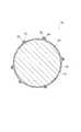
図2は、本実施形態に係るワイヤ工具の横断面図である。また、図3は、本実施形態に係るワイヤ工具の横断面の外周面付近を拡大した図である。図2および3に示すように、ワイヤ工具10の外周面14には、Ni等の鍍金層18が形成され、超砥粒16が鍍金層18に埋め込まれるように電着されている。超砥粒16の表面には、電着時の効率を向上させるため、Ti、Ni、Cu、TiC、SiCから選択されるいずれかからなる被覆層20が形成されている。より好適には、TiCからなる被覆層20とすることが、超砥粒16および被覆層20の抵抗率が大きくなるため好適である。超砥粒16の平均粒径は、1〜60μmとすることが好適である。 FIG. 2 is a cross-sectional view of the wire tool according to the present embodiment. Moreover, FIG. 3 is the figure which expanded the outer peripheral surface vicinity of the cross section of the wire tool which concerns on this embodiment. As shown in FIGS. 2 and 3, a plating
超砥粒16に形成された被覆層20の厚さは、0.1μm未満、より好ましくは0.05μm以下と薄くされている。または、被覆層20の質量は、超砥粒16の質量の10%未満、より好ましくは5%未満となるように薄くされている。 The thickness of the
従来の被覆砥粒の被覆層の厚さは0.1〜10μmの範囲内の厚さであり、例えば1μmと厚くされていた(例えば、前述の特許文献3の段落(0033)参照)。また、従来の被覆砥粒における被覆層の質量百分率は、例えば30〜55%と大きくされており、厚い被覆層が設けられていた(例えば、前述の特許文献1の段落(0037)参照)。これは、電着の効率を上げるためには、被覆層の厚さを厚くして導電性を高めることが重要であると考えられていたからである。 The thickness of the coating layer of the conventional coated abrasive grains is in the range of 0.1 to 10 μm, for example, 1 μm (for example, refer to paragraph (0033) of Patent Document 3 described above). Moreover, the mass percentage of the coating layer in the conventional coated abrasive is increased to, for example, 30 to 55%, and a thick coating layer is provided (for example, see paragraph (0037) of Patent Document 1 described above). This is because, in order to increase the efficiency of electrodeposition, it has been thought that it is important to increase the conductivity by increasing the thickness of the coating layer.
図5は、従来のワイヤ工具の芯線に鍍金浴中で超砥粒が電着される様子を示す図である。図5に示すように、鍍金浴36中で被覆層20が厚い超砥粒16を芯線12に電着すると、厚い被覆層20により被覆された超砥粒16の導電性が高いため、超砥粒16が凝集して電着されやすい。このため、余分な量の超砥粒16が電着されることになる。 FIG. 5 is a diagram showing a state in which superabrasive grains are electrodeposited on a core wire of a conventional wire tool in a plating bath. As shown in FIG. 5, when the
図6は、本実施形態に係るワイヤ工具の芯線に鍍金浴中で超砥粒が電着される様子を示す図である。図6に示すように、鍍金浴36中で本実施形態に係る被覆層20が薄い超砥粒16を芯線12に電着すると、超砥粒16の電着時に超砥粒16に過度の電流が流れないため、余分な量の超砥粒16が芯線12に電着されることがない。そのため、芯線12の外周面14には、適用な密度で超砥粒16が単層に電着される。これにより、超砥粒16は芯線12から脱離しにくいため、ワイヤ工具の寿命は長いものとできる。また、超砥粒を電着した後に、余分な超砥粒を除去する処理をする必要がないため、製造コストの手間やコストを削減することができる。 FIG. 6 is a diagram illustrating a state in which superabrasive grains are electrodeposited on the core wire of the wire tool according to the present embodiment in a plating bath. As shown in FIG. 6, when the
超砥粒の表面に薄い被覆層を形成する方法としては、CVD法、PVD法、めっき法、浸漬法等を用いて形成することができる。 As a method for forming a thin coating layer on the surface of the superabrasive grains, it can be formed using a CVD method, a PVD method, a plating method, a dipping method, or the like.
図4は、本実施形態に係るワイヤ工具の芯線に超砥粒を電着する工程を示す図である。図4に示すように、鍍金槽34は鍍金浴36によって満たされている。鍍金浴36は、例えば、スルファミン酸ニッケル、塩化ニッケル、ホウ酸からなるスルファミン酸浴とされている。鍍金浴36には、前述の薄い被覆層が表面に形成された超砥粒が混入されている。芯線12は、図中の矢印方向に鍍金浴36中に浸漬されつつ搬送されるようになっている。芯線12を保持するプーリの一部は、陰極38とされ、負電位を印加されるようになっている。また、鍍金浴36中に浸漬された芯線12を囲繞するように陽極40が設けられ、正電位を印加されるようになっている。 FIG. 4 is a diagram illustrating a process of electrodepositing superabrasive grains on the core wire of the wire tool according to the present embodiment. As shown in FIG. 4, the
電着時には、芯線12を矢印方向に搬送しつつ、陰極38および陽極40に電圧を印加する。芯線12の搬送速度は、1m/分以上が可能となる。鍍金浴36中の超砥粒の被覆層は薄いため、電着に必要な最小限度の電流しか流れない。そのため、前述した図6に示したように、超砥粒は芯線12に単層で電着される。このため、電着された超砥粒は脱離しにくく、ワイヤ工具の寿命を長いものとできる。また、その後に余分の超砥粒を除去する工程を省くことができる。 At the time of electrodeposition, a voltage is applied to the
尚、本発明のワイヤ工具は、上記した実施の形態に限定されるものではなく、本発明の要旨を逸脱しない範囲内において種々変更を加え得ることは勿論である。 Note that the wire tool of the present invention is not limited to the above-described embodiment, and it is needless to say that various modifications can be made without departing from the gist of the present invention.
10…ワイヤ工具、12…芯線、14…外周面、16…超砥粒、18…鍍金層、20…被覆層、34…鍍金槽、36…鍍金浴、38…陰極、40…陽極。DESCRIPTION OF
Claims (2)
Translated fromJapanese全ての前記超砥粒の表面はTiC及びSiCから選択されるいずれかからなる被覆層で覆われ、
前記被覆層の厚さは、0.1μm未満であり、
前記超砥粒は、前記線状体の外周面に単層で固定されている電着ワイヤ工具。An electrodeposited wire tool having a plurality of superabrasive grains having anaverage particle diameter of 1 to 60 μm fixed to the outer peripheral surface of the linear bodyonly by a plating layer by electrodeposition,
The surfaces ofall the superabrasive grains are covered with a coating layer made ofany one selected from TiC and SiC ,
The coating layer has a thickness of less than 0.1 μm;
The superabrasive grain is an electrodeposited wire tool in which a single layer is fixed to the outer peripheral surface of the linear body.
全ての前記超砥粒の表面はTiC及びSiCから選択されるいずれかからなる被覆層で覆われ、
前記被覆層の質量は、前記超砥粒の質量の10%未満であり、
前記超砥粒は、前記線状体の外周面に単層で固定されている電着ワイヤ工具。An electrodeposition wire toolcomprising a plurality of superabrasive grains having anaverage particle diameter of 1 to 60 μm fixedonly on a plating layer by electrodeposition on the outer peripheral surface of a linear body,
The surfaces ofall the superabrasive grains are covered with a coating layer made ofany one selected from TiC and SiC ,
The mass of the coating layer is less than 10% of the mass of the superabrasive grains,
The superabrasive grain is an electrodeposited wire tool in which a single layer is fixed to the outer peripheral surface of the linear body.
Priority Applications (5)
| Application Number | Priority Date | Filing Date | Title |
|---|---|---|---|
| JP2004380182AJP4139810B2 (en) | 2004-12-28 | 2004-12-28 | Electrodeposition wire tool |
| US11/666,098US7704127B2 (en) | 2004-12-28 | 2005-09-05 | Electrodeposited wire tool |
| KR1020067017485AKR101147519B1 (en) | 2004-12-28 | 2005-11-09 | Electrodeposition wire tool |
| PCT/JP2005/020537WO2006070534A1 (en) | 2004-12-28 | 2005-11-09 | Electrodeposition wire tool |
| CN2005800094309ACN1933942B (en) | 2004-12-28 | 2005-11-09 | Electrodeposited wire tools |
Applications Claiming Priority (1)
| Application Number | Priority Date | Filing Date | Title |
|---|---|---|---|
| JP2004380182AJP4139810B2 (en) | 2004-12-28 | 2004-12-28 | Electrodeposition wire tool |
Publications (2)
| Publication Number | Publication Date |
|---|---|
| JP2006181698A JP2006181698A (en) | 2006-07-13 |
| JP4139810B2true JP4139810B2 (en) | 2008-08-27 |
Family
ID=36614660
Family Applications (1)
| Application Number | Title | Priority Date | Filing Date |
|---|---|---|---|
| JP2004380182AExpired - LifetimeJP4139810B2 (en) | 2004-12-28 | 2004-12-28 | Electrodeposition wire tool |
Country Status (5)
| Country | Link |
|---|---|
| US (1) | US7704127B2 (en) |
| JP (1) | JP4139810B2 (en) |
| KR (1) | KR101147519B1 (en) |
| CN (1) | CN1933942B (en) |
| WO (1) | WO2006070534A1 (en) |
Cited By (1)
| Publication number | Priority date | Publication date | Assignee | Title |
|---|---|---|---|---|
| KR20180063168A (en) | 2015-09-30 | 2018-06-11 | 후루카와 덴키 고교 가부시키가이샤 | Diamond abrasive and wire tools for wire tools |
Families Citing this family (35)
| Publication number | Priority date | Publication date | Assignee | Title |
|---|---|---|---|---|
| US8291895B2 (en)* | 2007-09-05 | 2012-10-23 | University Of South Carolina | Methods, wires, and apparatus for slicing hard materials |
| JP2009066689A (en)* | 2007-09-12 | 2009-04-02 | Read Co Ltd | Fixed abrasive grain wire saw |
| WO2009125780A1 (en)* | 2008-04-11 | 2009-10-15 | 株式会社アライドマテリアル | Electrodeposited wire tool and method of producing same |
| US20090274099A1 (en)* | 2008-05-02 | 2009-11-05 | Qualcomm Incorporated | Methods and apparatus for communicating transmitter information in a communication network |
| US9095914B2 (en)* | 2008-09-16 | 2015-08-04 | Diamond Innnovations Inc | Precision wire saw including surface modified diamond |
| TW201111106A (en)* | 2009-03-02 | 2011-04-01 | Sumitomo Electric Industries | Diamond wire saw, process for manufacturing diamond wire saw |
| CN101531035B (en)* | 2009-04-21 | 2014-04-16 | 青岛科技大学 | A method for manufacturing electroplating diamond wire saw |
| WO2010125085A1 (en)* | 2009-04-29 | 2010-11-04 | Nv Bekaert Sa | A sawing wire with abrasive particles partly embedded in a metal wire and partly held by an organic binder |
| MX2012001810A (en) | 2009-08-14 | 2012-06-01 | Saint Gobain Abrasives Inc | ABRASIVE ITEMS THAT INCLUDE ABRASIVE PARTICLES UNITED TO A LONG BODY. |
| KR101433750B1 (en) | 2009-08-14 | 2014-08-27 | 생-고뱅 어브레이시브즈, 인코포레이티드 | Abrasive articles including abrasive particles bonded to an elongated body, and methods of forming thereof |
| KR20110018642A (en)* | 2009-08-18 | 2011-02-24 | 일진다이아몬드(주) | Wire saw |
| TWI461249B (en)* | 2010-04-27 | 2014-11-21 | Kinik Co | Wire saw and method for fabricating the same |
| WO2011138192A2 (en) | 2010-05-04 | 2011-11-10 | Nv Bekaert Sa | Fixed abrasive sawing wire with removable protective coating |
| KR101186633B1 (en)* | 2010-05-17 | 2012-09-27 | 일진다이아몬드(주) | Wire tool |
| CN102069533A (en)* | 2010-11-25 | 2011-05-25 | 宋建华 | Multi-stranded diamond wire and production process thereof |
| TWI466990B (en) | 2010-12-30 | 2015-01-01 | Saint Gobain Abrasives Inc | Abrasive article and forming method |
| JPWO2012124717A1 (en)* | 2011-03-15 | 2014-07-24 | 栃木住友電工株式会社 | Abrasive fixed metal wire and method for manufacturing the same |
| CN102729343A (en)* | 2011-03-29 | 2012-10-17 | 中国砂轮企业股份有限公司 | Scroll saw and manufacturing method thereof |
| CN102729344A (en)* | 2011-04-11 | 2012-10-17 | 筱崎智彦 | Fretsaw structure with fixed abrasive particles |
| GB201108991D0 (en) | 2011-05-27 | 2011-07-13 | Element Six Ltd | Tool elements and method for making same |
| CN102357930A (en)* | 2011-08-18 | 2012-02-22 | 江苏神龙光电科技有限公司 | Photovoltaic silicon material diamond band saw blade and processing method thereof |
| JP5802275B2 (en)* | 2011-09-14 | 2015-10-28 | 株式会社ファシリティ | Solid particulate adhering wire and method for producing the solid particulate adhering wire |
| CN107263340A (en) | 2011-09-16 | 2017-10-20 | 圣戈班磨料磨具有限公司 | abrasive article and forming method |
| US8567385B2 (en) | 2011-09-22 | 2013-10-29 | Chung-Shan Institute of Science and Technology, Armaments, Bureau, Ministry of National Defense | Fret saw including a cutting wire provided with fixed abrasive grains each including a core coated with a hard film |
| WO2013049204A2 (en) | 2011-09-29 | 2013-04-04 | Saint-Gobain Abrasives, Inc. | Abrasive articles including abrasive particles bonded to an elongated substrate body having a barrier layer, and methods of forming thereof |
| CN103192461A (en)* | 2012-01-04 | 2013-07-10 | 森茂科技股份有限公司 | Manufacturing method of high wear-resistant wire saw |
| TW201404527A (en) | 2012-06-29 | 2014-02-01 | Saint Gobain Abrasives Inc | Abrasive article and method of forming |
| TW201402274A (en) | 2012-06-29 | 2014-01-16 | Saint Gobain Abrasives Inc | Abrasive article and method of forming |
| TWI477343B (en) | 2012-06-29 | 2015-03-21 | Saint Gobain Abrasives Inc | Abrasive article and method of forming |
| CN102765142A (en)* | 2012-08-06 | 2012-11-07 | 无锡嘉瑞光伏有限公司 | Steel wire for cutting silicon wafers and use method thereof |
| TW201441355A (en) | 2013-04-19 | 2014-11-01 | Saint Gobain Abrasives Inc | Abrasive article and method of forming |
| TWI553153B (en)* | 2013-06-28 | 2016-10-11 | 聖高拜陶器塑膠公司 | Nickel coated diamond particles and method of making said particles |
| CN107427943B (en) | 2015-03-13 | 2019-07-05 | 江阴贝卡尔特合金材料有限公司 | Manufacturing method of consolidated abrasive saw wire with metal alloy fixing layer and manufactured saw wire |
| TWI621505B (en) | 2015-06-29 | 2018-04-21 | 聖高拜磨料有限公司 | Abrasive article and forming method |
| CN106926148B (en)* | 2017-02-08 | 2020-07-14 | 上海交通大学 | Method for preparing single-layer diamond abrasive tools by chemical vapor deposition |
Family Cites Families (13)
| Publication number | Priority date | Publication date | Assignee | Title |
|---|---|---|---|---|
| JPS4738690Y1 (en) | 1970-12-03 | 1972-11-22 | ||
| CA1194318A (en) | 1981-05-18 | 1985-10-01 | Edwin A. Pascoe | Dry grinding cemented carbide workpieces with silver- coated diamond grit |
| JPS58186569A (en) | 1982-04-23 | 1983-10-31 | Disco Abrasive Sys Ltd | Electrodeposited grindstone |
| JPH0224062A (en) | 1988-07-14 | 1990-01-26 | Toyoda Mach Works Ltd | Electrodeposited grindstone and manufacture thereof |
| JPH05245759A (en) | 1991-03-19 | 1993-09-24 | Noritake Dia Kk | Coated abrasive grain inclusion cutting-off wheel |
| JPH07292350A (en) | 1994-04-26 | 1995-11-07 | Idemitsu Kosan Co Ltd | Polyolefin resin coated abrasive for cutting or polishing, cutting / polishing method using the abrasive, and cutting / polishing liquid using the abrasive |
| JP3119098B2 (en) | 1994-10-17 | 2000-12-18 | 株式会社ティ・ケー・エックス | Diamond abrasive grains, grindstones and methods for producing them |
| JP2001025975A (en) | 1999-07-15 | 2001-01-30 | Ricoh Co Ltd | Wire tool and manufacturing method thereof |
| JP2001198834A (en) | 2000-01-13 | 2001-07-24 | Allied Material Corp | Diamond wheel using SiC coated abrasive |
| JP2002166370A (en) | 2000-12-04 | 2002-06-11 | Noritake Diamond Ind Co Ltd | Electrodeposited grinding wheel and method of manufacturing the same |
| JP4157724B2 (en) | 2002-05-20 | 2008-10-01 | 株式会社ノリタケカンパニーリミテド | Wire saw manufacturing method and manufacturing apparatus |
| JP2004027283A (en) | 2002-06-25 | 2004-01-29 | Yasuhiro Tani | Plating equipment and wire tools |
| JP2004050301A (en) | 2002-07-16 | 2004-02-19 | Noritake Co Ltd | Wire saw and its manufacturing method |
- 2004
- 2004-12-28JPJP2004380182Apatent/JP4139810B2/ennot_activeExpired - Lifetime
- 2005
- 2005-09-05USUS11/666,098patent/US7704127B2/enactiveActive
- 2005-11-09KRKR1020067017485Apatent/KR101147519B1/enactiveActive
- 2005-11-09CNCN2005800094309Apatent/CN1933942B/enactiveActive
- 2005-11-09WOPCT/JP2005/020537patent/WO2006070534A1/ennot_activeApplication Discontinuation
Cited By (1)
| Publication number | Priority date | Publication date | Assignee | Title |
|---|---|---|---|---|
| KR20180063168A (en) | 2015-09-30 | 2018-06-11 | 후루카와 덴키 고교 가부시키가이샤 | Diamond abrasive and wire tools for wire tools |
Also Published As
| Publication number | Publication date |
|---|---|
| JP2006181698A (en) | 2006-07-13 |
| KR101147519B1 (en) | 2012-05-21 |
| CN1933942A (en) | 2007-03-21 |
| KR20070090074A (en) | 2007-09-05 |
| US20090120422A1 (en) | 2009-05-14 |
| CN1933942B (en) | 2010-05-12 |
| WO2006070534A1 (en) | 2006-07-06 |
| US7704127B2 (en) | 2010-04-27 |
Similar Documents
| Publication | Publication Date | Title |
|---|---|---|
| JP4139810B2 (en) | Electrodeposition wire tool | |
| JP4703448B2 (en) | Resin bond wire saw | |
| JP2009066689A (en) | Fixed abrasive grain wire saw | |
| JP2006181701A (en) | Electrodeposition wire tool and manufacturing method thereof | |
| TW201136688A (en) | Wire saw and method for fabricating the same | |
| WO2013179434A1 (en) | Fixed-abrasive-grain wire-saw, method for manufacturing same, and method for cutting workpiece using same | |
| JPH06114739A (en) | Electrodeposition grinding wheel | |
| CN108136567B (en) | Diamond abrasive grain for wire tool and wire tool | |
| RU2653378C2 (en) | Abrasive sawing wire, manufacturing process and use | |
| JP5066508B2 (en) | Fixed abrasive wire saw | |
| JP2007152485A (en) | Manufacturing method of saw wire | |
| JP5390138B2 (en) | Abrasive grain, electrodeposition tool, method for producing abrasive grain, and method for producing electrodeposition tool | |
| KR20110048659A (en) | Wire saw and manufacturing method of wire saw | |
| JP5285381B2 (en) | Super abrasive tool | |
| JP2013136142A (en) | Manufacturing method of diamond abrasive grain, manufacturing method of wire tool and wire tool | |
| JP2014188655A (en) | Wire tool for polycrystalline silicon cutting and polycrystalline silicon cutting method | |
| JP2007307669A (en) | Wire electric discharge machine and wire electric discharge machining method | |
| JP2013500170A (en) | Wire saw | |
| JP6578525B2 (en) | Abrasive | |
| JP2009078321A (en) | Electroplated tool and method of manufacturing the same | |
| KR102137792B1 (en) | Method for manufacturing multi-layer electro deposition cutting tool and multi-layer electro deposition cutting tool manufactured thereby | |
| JP2003334763A (en) | Fixed abrasive grain wire saw | |
| KR101277468B1 (en) | Wire cutting tool and its manufacturing method | |
| JP2014172115A (en) | Fixed abrasive grain wire, and method for production thereof | |
| JP2002126990A (en) | Wire saw and manufacturing method therefor |
Legal Events
| Date | Code | Title | Description |
|---|---|---|---|
| A621 | Written request for application examination | Free format text:JAPANESE INTERMEDIATE CODE: A621 Effective date:20071114 | |
| A871 | Explanation of circumstances concerning accelerated examination | Free format text:JAPANESE INTERMEDIATE CODE: A871 Effective date:20071114 | |
| A975 | Report on accelerated examination | Free format text:JAPANESE INTERMEDIATE CODE: A971005 Effective date:20071207 | |
| A131 | Notification of reasons for refusal | Free format text:JAPANESE INTERMEDIATE CODE: A131 Effective date:20071218 | |
| A521 | Request for written amendment filed | Free format text:JAPANESE INTERMEDIATE CODE: A523 Effective date:20080218 | |
| A02 | Decision of refusal | Free format text:JAPANESE INTERMEDIATE CODE: A02 Effective date:20080311 | |
| A521 | Request for written amendment filed | Free format text:JAPANESE INTERMEDIATE CODE: A523 Effective date:20080425 | |
| A911 | Transfer to examiner for re-examination before appeal (zenchi) | Free format text:JAPANESE INTERMEDIATE CODE: A911 Effective date:20080515 | |
| TRDD | Decision of grant or rejection written | ||
| A01 | Written decision to grant a patent or to grant a registration (utility model) | Free format text:JAPANESE INTERMEDIATE CODE: A01 Effective date:20080603 | |
| A01 | Written decision to grant a patent or to grant a registration (utility model) | Free format text:JAPANESE INTERMEDIATE CODE: A01 | |
| A61 | First payment of annual fees (during grant procedure) | Free format text:JAPANESE INTERMEDIATE CODE: A61 Effective date:20080609 | |
| R150 | Certificate of patent or registration of utility model | Ref document number:4139810 Country of ref document:JP Free format text:JAPANESE INTERMEDIATE CODE: R150 Free format text:JAPANESE INTERMEDIATE CODE: R150 | |
| FPAY | Renewal fee payment (event date is renewal date of database) | Free format text:PAYMENT UNTIL: 20110613 Year of fee payment:3 | |
| FPAY | Renewal fee payment (event date is renewal date of database) | Free format text:PAYMENT UNTIL: 20140613 Year of fee payment:6 | |
| R250 | Receipt of annual fees | Free format text:JAPANESE INTERMEDIATE CODE: R250 | |
| R250 | Receipt of annual fees | Free format text:JAPANESE INTERMEDIATE CODE: R250 | |
| R250 | Receipt of annual fees | Free format text:JAPANESE INTERMEDIATE CODE: R250 | |
| R250 | Receipt of annual fees | Free format text:JAPANESE INTERMEDIATE CODE: R250 | |
| R250 | Receipt of annual fees | Free format text:JAPANESE INTERMEDIATE CODE: R250 | |
| EXPY | Cancellation because of completion of term |