JP4139603B2 - Timer with analog display of time-related information based on decimal system - Google Patents
Timer with analog display of time-related information based on decimal systemDownload PDFInfo
- Publication number
- JP4139603B2 JP4139603B2JP2002047478AJP2002047478AJP4139603B2JP 4139603 B2JP4139603 B2JP 4139603B2JP 2002047478 AJP2002047478 AJP 2002047478AJP 2002047478 AJP2002047478 AJP 2002047478AJP 4139603 B2JP4139603 B2JP 4139603B2
- Authority
- JP
- Japan
- Prior art keywords
- time
- decimal
- approximate
- timer
- display
- Prior art date
- Legal status (The legal status is an assumption and is not a legal conclusion. Google has not performed a legal analysis and makes no representation as to the accuracy of the status listed.)
- Expired - Fee Related
Links
Images


Classifications
- G—PHYSICS
- G04—HOROLOGY
- G04B—MECHANICALLY-DRIVEN CLOCKS OR WATCHES; MECHANICAL PARTS OF CLOCKS OR WATCHES IN GENERAL; TIME PIECES USING THE POSITION OF THE SUN, MOON OR STARS
- G04B19/00—Indicating the time by visual means
- G—PHYSICS
- G04—HOROLOGY
- G04C—ELECTROMECHANICAL CLOCKS OR WATCHES
- G04C17/00—Indicating the time optically by electric means
- G—PHYSICS
- G04—HOROLOGY
- G04B—MECHANICALLY-DRIVEN CLOCKS OR WATCHES; MECHANICAL PARTS OF CLOCKS OR WATCHES IN GENERAL; TIME PIECES USING THE POSITION OF THE SUN, MOON OR STARS
- G04B19/00—Indicating the time by visual means
- G04B19/06—Dials
- G04B19/08—Geometrical arrangement of the graduations
- G04B19/085—Geometrical arrangement of the graduations varying from the normal 12 hour arrangement
Landscapes
- Physics & Mathematics (AREA)
- General Physics & Mathematics (AREA)
- Geometry (AREA)
- Electromechanical Clocks (AREA)
Description
Translated fromJapanese【0001】
【産業上の利用分野】
本発明は、時間および分インジケータ部材を用いて従来の第1時間関連情報を読み取るとともに、少なくとも1日を千分の1に分割した時間で表されるような十進法に基づく第2時間関連情報を同時に読み取ることができるようにするアナログディスプレイ計時器に関する。
【0002】
【従来の技術】
近年、時間を計測する代替システムが提案されるようになった。このシステムにおいては、1日は、従来行われていたように時間、分、秒に分割されることはなく、通例「ビート」という名称で呼ばれる1日の千分の1の単位に分割される。その長さは86.4秒に相当する。したがって24時間は、値「000」から「999」の間に展開される時間である、1,000個の1日の千分の1または「ビート」に分割される。この時間計測用代替システムは、特にインターネットを行う人々が使用することや、空間帯および時間帯という概念を不要にすることを意図するものである。この時間測定システムはまた、従来の時間情報とは明瞭に区別されることも意図されている。
【0003】
本発明の概括的な目的は、従来の時間関連情報(たとえば現地時間など)をディスプレイする一対の時間および分インジケータ要素を従来の通りに含むとともに、さらに前述の十進法に基づく時間関連情報を同時に読み取ることができるようにするアナログディスプレイ計時器を提案することである。
【0004】
より詳細には、従来のアナログディスプレイ計時器に関して変更が少ししか必要ないような計時器を提案することが望ましい。
【0005】
従来の時間関連情報をディスプレイするための一対の時針と分針と、前述の十進法に基づく第2時間情報用のディスプレイ手段とを含むアナログディスプレイ計時器は、スイス特許第690 254号からすでに公知である。この文献によると、十進法による時間情報は、単一の追加針(好ましくは24時間に1回転する針)を用いて読み取られ、上記追加針は、たとえば計時器に取り付けられた外側ベゼル上に配置される1日の千分の1の目盛りと向かい合って回転する。上記外側ベゼルは、ユーザが位置する時間帯の関数として十進法による時間情報を調節できるように、回転可能な状態で取り付けられることが好ましい。
【0006】
外側ベゼルに付け加えられる1日の千分の1の目盛りを除けば、スイス特許第690 254号において開示される計時器は、スイス特許第451 827号に開示されるユニバーサル計時器などといった従来のユニバーサル計時器に関して、いかなる変更も特に必要としない。事実この文献は、時針と分針を含むとともに、24時間帯のマークを有する外側回転ベゼルに向かい合って回転する24時間針をさらに含むユニバーサル・アナログディスプレイ計時器を開示している。
【0007】
【発明が解決しようとする課題】
スイス特許第690 254号の計時器は、特に腕時計に適用した場合、ユーザが十進法に基づく時間を正確に読み取ることができないという主要な欠点を有する。実際のところ腕時計のサイズが小さい場合、ベゼル(または計時器のダイヤル)に読み取れるように数多くの目盛りを付け加えることは現実的に不可能である。スイス文献第690 254号の図2および3から分かるように、目盛り記号はせいぜい1日の千分の5ごと、すなわち432秒に相当する時間間隔をおいて付される、つまり7分より少し多い時間間隔をおいて付される。面積を考慮すると、これよりも多い数の目盛り記号(この場合200個よりも多い記号)を付けることは、現実的に考えられない。この解決策においては時間の読み取りはでたらめとなり、結果的に数十分という読み取りエラーが発生する可能性がある。
【0008】
したがって、たとえば会議または出来事の発生を確定するという目的のために参照時間として使用することができるように十進法による時間情報を十分正確に読み取れるようにするような、より適切な解決策を見つけなければならない。
【0009】
【課題を解決するための手段】
この目的に答えるため、本発明は、独立クレーム1に列挙される特徴を有するアナログディスプレイ計時器に関する。
本発明の有利な実施態様は従属クレームの主題を形成する。
【0010】
本発明によると十進法に基づく時間情報は、分インジケータ部材と、1日の千分の1で表される正規の時間(1時、2時、・・・23時、24時)の少なくとも近似十進法値を表示する、つまり少なくとも1日の千分の41または42(1時間はおよそ1日千分の41.7に相当する)ずつ表示する補足的アナログディスプレイ手段とを組み合わせて使用することによって得られる。本発明によると、分インジケータ部材は、一方で従来通りの分を表示する一方、補足的アナログディスプレイ手段によって表示される近似十進法値に加算される対応する十進法値を表示する。正規の時間に近い(概算の誤差は決して1日の千分の1を越えることはない)にもかかわらず、分インジケータ部材および追加ディスプレイ部材は、ユーザが特に会議を確定する目的のため上記十進法による時間情報をたよりとすることができるだけの十分に正確な時間情報をユーザに提供する。
【0011】
近似十進法値は、ユーザが位置する時間帯の関数として十進法による時間情報を訂正できるようにするため、時間および分インジケータ部材から独立して、回転で調節可能なディスプレイ部材によって保持されることが好ましい。
【0012】
本発明においては、概して2つの好ましい実施態様の原理を区別することができる。第1の実施態様原理によると、十進法による時間情報は、従来の時間情報を読み取るために用いられる分および時間インジケータ部材によって表示される。そして補足的アナログディスプレイ手段は、少なくとも正規時間の近似十進法値の表示が示される、回転で調節可能な追加ディスプレイ部材をたよりとする(図1から3および8を参照すること)。
【0013】
本発明による第2の実施態様原理によると、十進法による時間情報は、分インジケータ部材と、時間インジケータ部材とは異なる作動機構によって駆動される別の追加部材とによって表示される。この第2原理の2つの代替的実施態様について説明する。1つの実施態様は、上記作動機構によって駆動される追加インジケータ部材を使用することから構成され、このインジケータ部材は好ましくは回転で調節可能な、かつ少なくとも正規時間の近似十進法値が示されるようなディスプレイ部材と連結されている(図4から6を参照すること)。もう1つの代替的実施態様は、上記作動機構を介して、近似十進法値の表示が示されるディスプレイ部材を直接駆動することから構成され、このインジケータ部材は、この場合は計時器に付け加えられる固定された目盛りに置き換えられる(図7を参照すること)。
【0014】
前述した2つの実施態様原理においては、特に共通する特徴として、分インジケータ部材と補足的アナログディスプレイ手段とが、ともに前述の十進法に基づく時間情報を正確に読み取れるようにしている。
【0015】
本発明のその他の特徴および利点は、非限定的な例として与えられる付属の図面を参照しながら以下の詳細な説明を読み取ることによって、より明瞭になるであろう。
【0016】
【発明の好適な実施態様】
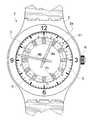
図1は、本発明による計時器の第1の実施形態を示す。この例において計時器は、総合的に参照番号1によって表されるアナログディスプレイ腕時計の形をとる。この腕時計1は、特に、および一般的に、(図示されない)作動機構を封入するケース中間部2と、ベゼル2aと、クリスタル3と、第1アナログディスプレイ手段と、時間設定竜頭6とを含む。第1アナログディスプレイ手段はダイヤル5と作動機構によって駆動される第1および第2時間および分インジケータ部材4a、4b(ここでは一対の時針と分針)とを含む。図示される計時器において使用される作動機構は従来の12時間作動機構である。すなわち時間インジケータ部材4aは12時間で1回転を完了する。ただし、本発明は上記インジケータ部材が24時間で1回転を完了するような24時間作動機構を含む計時器にも適用可能であるということは理解されるであろう。
【0017】
本発明によると、計時器はさらに、時間が少なくとも1日の千分の1に分割されるような十進法に基づく時間情報を同時に読み取ることができるようにする第2アナログディスプレイ手段を含む。先に述べたように、この十進法によると、時間は「000」から「999」の間で変化する3桁の数字で形成される。「000」は、グリニッジ平均時の略語GMTとの類推により以下BMT(Biel平均時)と称される、スイスの町Bienneを通過する経線上の冬時間における真夜中に相当する。
【0018】
本発明によると第2アナログディスプレイ手段は、特にダイヤル5と分インジケータ部材4bを第1アナログディスプレイ手段と共有する。この分インジケータ部材4bは、十進法による時間情報が形成されるようにする第2ディスプレイ手段の残りの部分を形成する補足的アナログディスプレイ手段とともに使用される。
【0019】
前述したように、特に上記第1実施形態によって説明される本発明による第1の実施形態の原理によると、補足的アナログディスプレイ手段は時間インジケータ部材4aと、参照番号7で示される回転で調整可能な追加ディスプレイ手段とを含む。上記追加ディスプレイ手段は、この例においてはインジケータ部材4a、4bと同心に取り付けられる日付ディスクに類似するインジケータディスクによって形成される。しかし日付ディスクとは異なり、このディスプレイ部材7は作動機構によって回転中に駆動されることはなく、異なる数の角度セクターに再分割されている。ディスプレイ部材7の角度位置は、時間設定竜頭6を用いて簡単に調整される。回転によるこの調節を可能にするために用いられる機構は、日付を訂正できるようにする従来の機構と同様のものであり、当該技術分野における技術者には公知のものであるため、ここでは説明しない。本実施形態においては、補足的アナログディスプレイはこのディスク7とインジケータ部材4bとによって構成されている。
【0020】
ダイヤル5は一般に、通常周縁部全体に配置されて時間および分の表示を行うような複数のマークを有する。これらの表示にさらに本ダイヤルは、60分の全期間にわたって対応する十進法値51も有する。1日の千分の1で表すと、60分はおよそ千分の41.7に相当する。したがってこの例においては、上記ダイヤルには、分目盛りに向き合う「0」から「41」まで1日の千分の1ごとの目盛りが付けられている。
【0021】
ディスプレイ部材7は通常、正規の時間に対応する第1および第2近似十進法値71を各々有する12の角度セクターに再分割される。したがってBMTの真夜中は十進法値「000」で表され、BMTの1時は近似十進法値「042」、2時は近似十進法値「083」など、BMTの23時である近似十進法値の「958」まで表されている。この例において時間インジケータ部材4aは十進法による時間情報を導き出すために使用されている。この時間インジケータ部材4aはこの例においては12時間ごとに1回転すると仮定すると、ディスプレイ部材7は各角度セクターにおいて、互いに12時間ずつ離れた、すなわち1日の千分の500離れた一対の十進法値を有する。
【0022】
図1で説明される例においては、ディスプレイ部材7はBiel経線を含む時間帯に対して調節される。すなわち十進法値対「000−500」は、正午に位置付けられる。ニューヨーク(Bielの町に関して−6時間)に位置するユーザは、十進法値対「000−500」が6時に位置を定めるようにディスプレイ部材7を配置しなければならない。モスクワ(Bielの町に関して+2時間)に位置するユーザは、十進法値対「000−500」が2時に位置を定めるようにディスプレイ部材7を配置しなければならない。
【0023】
この第1の実施形態の原理によると、前述の十進法に基づく時間情報は、分インジケータ部材4bと時間インジケータ部材4aとによってそれぞれ表示される十進法値を加算することによって形成される。この例では、表示されている時間は(午後)12時47分である。したがって分インジケータ部材4bによってダイヤル5上に表示される十進法値は、1日の千分の32よりも少し上の値であり、時間インジケータ部材4aによってディスプレイ部材7上に表示される近似十進法値は「500」である。足し算することによって得られる合計十進法値はおよそ1日の千分の532であり、これはBMT12時47分の1日の千分の1で表される均等値に相当する。
【0024】
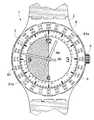
図2は、図1における第1実施形態の変形例を構成する本発明の第2の実施形態を示す。図2においては、ここでは参照番号7*で示されるディスプレイ部材上の近似十進法値71の表示の角度的配置が異なっている。図1において説明された例と比較すると、近似十進法値71は15°の角度で右側にオフセットされており、これにより時間インジケータ部材4aが常に決められたセクター、ここでは十進法値対「000−500」を含む角度セクターを指す。
【0025】
図1および2の実施形態において使用されるインジケータディスクは、図3に示されるように、たとえば回転外側ベゼルなどといった回転で調節可能なその他のあらゆるインジケータ部材と置き換えることができるということは、述べておかなければならない。
【0026】
また、図1および2の第1および第2実施形態において説明されるディスプレイ部材7、7*の再分割は、何にせよ限定されてはいないということも、述べておかなければならない。実際のところ上記ディスプレイ部材は、2×12個、3×12個、4×12個、またはそれ以上の角度セクターのうちいずれかの個数に再分割可能である。すなわち、上記ディスプレイ部材上に表示される種々の近似十進法値間において30、20、または15分という時間間隔で再分割が可能である。30分または15分ごとに再分割を行うと、都合よく、時差が1時間の整数倍ではないような時間帯が存在することを考慮に入れることができるようになるということを、特に述べておく。
【0027】
概してディスプレイ部材(それぞれ図1および2における7、7*)は、N×12の規則正しい角度セクターに再分割することが可能である。ここでNは整数であり、近似十進法値は、60/N分に相当する時間間隔を有する上記ディスプレイ部材の各角度セクターにおいて、上昇順に時計回りの方向に連続して表示される。ダイヤル5は、同様にN個の等しい角度セクターに再分割される。このセクターは、各角度セクターに対する60/N分という長さの分の数に対応する十進法値を各々表示する。
【0028】
計時器の代表的な寸法および制約を考慮すると、ダイヤル上およびディスプレイ部材上のマークの読みやすさという点から、再分割することのできる数は限られる。したがって48(N=4)または96(N=5)という数が、ディスプレイ部材上の再分割数として考えられ得る最大の数となる。
【0029】
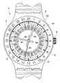
図3は、図1および2の実施形態に用いられた原理と同様の実施形態の原理に基づく本発明の第3の実施形態を示す。相違点の1つは、図1および2においてインジケータディスクの形をとる、回転で調節可能なディスプレイ部材が、この例においては総体的に参照番号8で示される回転外側ベゼルによって形成されるということである。別の相違点は、この回転ベゼル8が2×12=24の規則正しい角度セクター(N=2)に再分割されているということ、および参照番号81が付される近似十進法値が、およそ60/2=30分に相当する時間間隔を有する各角度セクター内に、つまり1日の千分の20または21ごとに、連続して表示されるということである。したがって表示される近似十進法値は、時計回りの方向に連続して「000」、「021」、「042」、「063」、・・・、「938」、「958」、「979」となる。このことからダイヤル5も、各々「0」から「20」までの目盛りを含む2つの角度セクターに再分割される。このうち参照番号51aが付された方は、時計回りの方向に12時から6時まで延びており、参照番号51bが付されたもう一方のセクターは、6時から12時まで延びている。
【0030】
図示された実施形態の場合、時間および分インジケータ部材4aおよび4bは、ほぼ十進法値「521」および「11」を、つまり足し算すると1日の千分の532をそれぞれ表示する。
【0031】
図1から3の実施形態の範囲内においては、ディスプレイ部材(図における7、7*または8)上にマークが付けられた2つの近似十進法値のうちどちらであるかを所定の時点において考慮するために識別するAM/PMインジケータ機構を追加することは、有用であると思われる。図1から3の実施形態においては、補足的ディスプレイ部材上にマークが付けられた第1および第2近似十進法値は、外側と内側という2つの別々の円上に配列されるということを述べておく。上記内側の円上にマークが付けられた近似十進法値は、Biel経線において午前(AM)に対応し、外側の円上にマークが付けられた十進法値は、Biel経線において午後(PM)に対応する。したがって、所定の時点において考慮しなければならない上記2つの十進法値のうちいずれをかを識別するため、Biel用に設定された、当該技術分野における技術者にとっては公知のAM/PMインジケータ機構を使用することができると思われる。このような機構はたとえば、AM/PMの再分割(またはこの代わりに0/+500)と向かい合って24時間につき1回転の割合で回転を行うインジケータ部材を含むことが可能である。
【0032】
すでに述べたように、以前に説明した原理を24時間作動機構に、すなわち時間インジケータ部材が24時間に1回転を完了するような作動機構にも当てはめることができるということは、理解されると思われる。この場合にはもはや、角度セクター内にマークが付けられた2つの十進法値のうち、いずれかを所定の時点において考慮に入れなければならないAM/PMインジケータ機構を追加して用いる必要はなく、回転可能な状態で調節できるディスプレイ部材の各角度セクターは、実際のところ、マークが付けられた十進法値を1つしか含まない。
【0033】
計時器には、回転可能な状態で調節できるディスプレイ部材上に表示される第1および第2近似十進法値が、12時間ごとに交互に遮蔽されるようにする機構を追加できれば都合がよい。図8は、図1において説明された第1実施形態に適用される、このような機構の説明図である。図1を参照してすでに呈示されている要素(図8において同じ参照番号によって表される)に加え、計時器は、正規時間の近似十進法値71の表示を有するディスプレイ部材7上に重ね合わされるディスク75を含む。ディスク75の一部は、ディスプレイ部材7が見えるようにするため、図示されていない。
【0034】
このディスク75には、(ここでは12個の)連続する第1開口76が設けられており、この第1開口を通して、ディスプレイ部材7の種々の角度セクター内に表示される、ディスク75の所定の角度位置に対する第1近似十進法値(ここでは「000」から「458」までの値)をみることができる。ディスク75には、上記第1連続開口76に関して(この例においては15°という)角度をもってオフセットされる(これもまた12個の)連続する第2開口77が設けられている。この第2開口を通して、ディスプレイ部材7の角度セクター内に表示される第2近似十進法値(ここでは「500」から「958」までの値)が、ディスク75の所定の角度位置で現れる。図8の例においては、第2連続開口77によって第2十進法値「500」から「958」までが見えるようになされるが、第1連続開口76は近似十進法値71の表示に関してオフセットされる。ディスク75はこのようにして第1近似十進法値「000」から「458」までを遮蔽する。
【0035】
ディスク75は、12時間ごとに1つの角度ステップ分の回転を行うように駆動される。この回転により、第1連続開口76および第2連続開口77は、それぞれ第1および第2近似十進法値71上に交互に導かれる。この例においては、ディスク75の回転は12日間で完了される、すなわちそれぞれ15°の24個の角度ステップをもって完了される。このように、ディスク75によって、回転可能な状態で調節できるディスプレイ部材7上に表示される第1または第2近似十進法値71が12時間ごとに交互に遮蔽されるようになる、ということが理解されると思われる。このことから12時間後、すなわち0時47分の時点においては、ディスク75は角度にして15°分オフセットされ、近似十進法値「000」から「458」までのみが現れるようになる。したがって足し算によって得られる十進法による時間情報は、千分の32日に等しい。
【0036】
本発明の第2の実施形態の原理について図4から7を参照しながら以下に説明するが、この第2実施形態によると、補足的アナログディスプレイ手段は、時間インジケータ部材4aではなく作動機構によって駆動される追加部材によって表示される。
【0037】
したがって図4は、上記第2の実施形態の原理に答える本発明の第4の実施形態を示す。図4において説明される計時器は、すでに先に述べたことに従って、ケース中間部2、クリスタル3、時間および分インジケータ部材4a、4b、ダイヤル5、および時間設定竜頭6を含む。この計時器はさらに、24時間に1回転する作動機構によって駆動される追加インジケータ部材4c(ここでは針の形をとる)と、ダイヤル5の下に時間および分インジケータ部材4aおよび4bと同心に取り付けられる追加ディスプレイ部材9とを含む。この追加ディスプレイ部材9は、参照番号91が付されたマークを有しており、このマークは、1日の千分の1で表される正規の時間の近似十進法値である。上記マーク91は、この例においては24個の、ダイヤル5内に配置される複数の孔5aを通して見ることができる。
【0038】
概してこの第2の実施形態の原理によると、十進法値表示を有するディスプレイ部材は、N×24の規則正しい角度セクターに再分割可能である。ここでNは以前と同様に整数であり、近似十進法値は、60/N分に相当する時間間隔を有するインジケータ部材の各角度セクターにおいて、上昇順に時計方向に連続して表示される。ダイヤル5は、同様にN個の等しい角度セクターに再分割され、このセクターは、各角度セクターに対する60/N分という長さの分の数に対応する十進法値を各々表示する。
【0039】
図4において説明される実施形態において、Nは1に相当し、したがって近似十進法値のマークを有するディスプレイ部材9は、24の等しい角度セクターに再分割される。ダイヤル5は、60分という総計時間全体について対応する十進法値51、つまり千分の「0」から「41」日までを有する1つのセクターのみを含む。
【0040】
先に述べた方法と同様に、十進法による時間情報は、一方で追加ディスプレイ部材9およびインジケータ部材4cによって表示され、他方で分インジケータ部材4bおよびダイヤル5によって表示される十進法値を加算することによって形成される。もう一度言うと、上記十進法値はこの例においては「500」および「32」、つまり足し算すると千分の532日である。
【0041】
近似十進法値91を有するディスプレイ部材9が回転で調節可能であると仮定すると、追加インジケータ部材4cは分および時間インジケータ部材から独立して調節可能である必要はないということが理解されよう。しかし回転で調節可能なディスプレイ手段を使用せず、近似十進法値のマークを直接ダイヤル上に(または計時器のベゼル上に)作るようにしてもまったく問題はない。この場合、追加インジケータ部材4cを、分および時間インジケータ部材から独立して調節可能にする必要がある。
【0042】
とはいえ、回転可能な状態で調節できるディスプレイ部材上に近似十進法値のマークを付けるということで構成される解決策には、一定の利点がある。実際のところ、図4において説明されるように、ディスプレイ部材9上にマークが付けられた近似十進法値91の種々の位置と向かい合うように参照番号21が付された24時間(1時、2時、・・・24時)のマークを付けることによって(この場合は計時器のベゼル2a)、ユーザは、従来の時間情報と十進法による時間情報との簡単かつ直接的な対応を手に入れることが可能である。特にユーザは、従来の十二進法と十進法との間でおおよその変換を行うことが可能である。事実ユーザが「300」の会議に合意する、または「300」に行事を予定すると仮定した場合、ユーザはこの「300」が、この例においては現地時間の午前7時頃に相当するということが容易にわかる。
【0043】
図5は、図4の第4実施形態の変形例を構成する、本発明の第5の実施形態を示す。ここでの1つの相違点は、ここでは参照番号9*で表されるディスプレイ部材上における近似十進法値91の表示の、角度を持たせた配列である。図4において説明された例と比較すると、十進法値は、追加インジケータ部材4cが常に一定のセクター、ここでは十進法値「500」を包含する角度セクター内を指すように、7.5°の角度で右の方へオフセットされる。
【0044】
図4の実施形態に関する別の相違点は、「1」から「24」までの24時間のマーク21がダイヤル5に付け加えられており、ベゼル2aには付されていないことである。
【0045】
図6は、図4および5の実施形態に対して用いられる原理と同様の実施形態の原理に基づく、本発明の第6の実施形態を示す。相違点は、特に、図4および5においてインジケータディスクの形をとる回転可能な状態で調節できるディスプレイ部材が、この例においては総体的に参照番号10で示される回転外側ベゼルで形成されるということである。別の相違点は、この回転ベゼル10が4×24=96の規則正しい角度セクター(N=4)に再分割されるということ、および101で表される近似十進法値が、おおよそ60/4=15分に相当する時間間隔有する各角度セクター内に、つまり1日の千分の10または11ごとに、連続して表示されるということである。したがって表示される近似十進法値は、時計回りの方向に連続して「000」、「010」、「021」、「031」、・・・、「969」、「979」、「990」となる。このことからダイヤル5もまた、各々「0」から「10」までの目盛りを包含する4つの角度セクターに再分割される。このセクターは、時計回りの方向にそれぞれ12時から3時、3時から6時、6時から9時、9時から12時まで延びており、上記目盛りは、図6において参照番号51aから51dでそれぞれ示される。ダイヤル5の周縁には、24時間のマーク21もまた付け加えられる。
【0046】
図示される実施形態の場合、追加インジケータ部材4cおよび分インジケータ部材4bは、それぞれ十進法値「531」および「1」を、つまり足し算すると1日の千分の532を表示する。
【0047】
再分割の数は異なっていてもよいということを、再度思い起こしたい。たとえば計時器の読み取りやすさを少し緩和するため、20分(N=3)ごとの分割を選択し、こうして回転ベゼル10およびダイヤル5をそれぞれ72個および3個の規則正しい角度セクターに再分割することが可能である。
【0048】
図7は、これもまた前述の第2実施形態の原理に答える、本発明の第7の実施形態を示す。図4から6の実施形態とは異なり、補足的アナログディスプレイ手段は、参照番号11で示される作動機構によって駆動される追加ディスプレイ部材と連結される固定目盛りであって、正規時間の近似十進法値11の表示を有する固定目盛り12を含む。追加ディスプレイ部材11は、図1、2、4または5の実施形態の(駆動されない)インジケータディスクと同様のディスク形状を有する。唯一の違いは、後者は(この例においては時計回りの方向に)24時間で1回転を完了するように作動機構によって駆動され、近似十進法値111のマークはディスプレイ部材11の回転方向のために反時計回りの方向に上昇順に配列される、ということである。ディスプレイ部材11の回転方向は逆転させることが可能である、すなわち上記部材は追加中間ラチェットを用いて反時計回りの方向に駆動可能であり、この場合近似十進法値111のマークは時計回りの方向に配列されなければならない、ということは理解されよう。
【0049】
固定目盛り12は、この例においてはダイヤル5の12時の場所に配置され、追加ディスプレイ部材11上に考慮しなければならない十進法値を表示する。勿論、この目盛り12は異なる位置に、またはベゼル2aなどといった計時器の別の部分に付されても良いということは、理解されるであろう。
【0050】
ディスプレイ部材11の角度位置は、時間設定竜頭6を用いて従来の方法で調整される。この例においては1時間というステップによって(または別の再分割が採用される場合には15、20または30分というステップによって)訂正を行うことができるように、当該技術分野における技術者にとって公知の訂正機構を使用することが好ましい。
【0051】
本明細書において説明される種々の実施形態に対し、付属のクレームによって規定される本発明の範囲から離れることなく、当該技術分野における技術者にとって自明であるような種々の変更および/または改良を行うことが可能であるということは、理解されるものと思われる。特に、時間および分インジケータ部材は、たとえば目盛りを有する回転ディスクなどといった針以外のインジケータ部材の形に作成することが可能であるということは、理解されるであろう。定義上マークおよび目盛りと関連する作動機構(一般的には種々の図において説明される針およびダイヤル)を介して時間表示を与えるような、あらゆるアナログディスプレイを用いて所望の結果を得ることができるということは、広く理解されることであると思われる。
【0052】
また本発明は、時間インジケータ部材が24時間で1回転を完了するような24時間作動機構にも適用可能であるということも、理解されるであろう。
【0053】
本発明は勿論、たとえば卓上時計や壁時計などといった腕時計以外の計時器にも適用可能である。
【図面の簡単な説明】
【図1】十進法による時間情報を得るためにすでに存在する分および時間インジケータ部材を特にたよりとする第1の実施形態の原理に答える、本発明の第1実施形態を示す。
【図2】十進法による時間情報を得るためにすでに存在する分および時間インジケータ部材を特にたよりとする第1の実施形態の原理に答える、本発明の第2実施形態を示す。
【図3】十進法による時間情報を得るためにすでに存在する分および時間インジケータ部材を特にたよりとする第1の実施形態の原理に答える、本発明の第3実施形態を示す。
【図4】十進法による時間情報を得るために、分インジケータ部材と、作動機構によって駆動される追加インジケータ部材とを特にたよりとする第2の実施形態の原理に答える、本発明の第4実施形態を示す。
【図5】十進法による時間情報を得るために、分インジケータ部材と、作動機構によって駆動される追加インジケータ部材とを特にたよりとする第2の実施形態の原理に答える、本発明の第5実施形態を示す。
【図6】十進法による時間情報を得るために、分インジケータ部材と、作動機構によって駆動される追加インジケータ部材とを特にたよりとする第2の実施形態の原理に答える、本発明の第6実施形態を示す。
【図7】十進法による時間情報を得るために、分インジケータ部材と、作動機構によって駆動される追加インジケータ部材とを特にたよりとする第2の実施形態の原理に答える、本発明の第7実施形態を示す。
【図8】追加ディスプレイ部材上に表示される近似十進法値が12時間ごとに交互に遮蔽されるようにする追加機構を含む、図1に説明される第1実施形態の有利な変形例を示す。
【符号の説明】
1 腕時計、2 中間部、3 クリスタル、4a 時針、4b 分針、5 ダイヤル、7 インジケータディスク、51 十進法値。[0001]
[Industrial application fields]
The present invention reads the conventional first time-related information using the hour and minute indicator member and obtains the second time-related information based on the decimal system as expressed by the time divided by one thousandth of at least one day. The present invention relates to an analog display timer that enables simultaneous reading.
[0002]
[Prior art]
In recent years, alternative systems for measuring time have been proposed. In this system, a day is not divided into hours, minutes, and seconds as is conventionally done, but is usually divided into units of a thousandth of a day called “beat”. . Its length corresponds to 86.4 seconds. Thus, 24 hours is divided into 1,000 thousandths of a day, or “beats,” which are the times that develop between the values “000” and “999”. This alternative system for measuring time is intended to be used by people on the Internet, and to eliminate the concept of space and time zones. This time measurement system is also intended to be clearly distinguished from conventional time information.
[0003]
A general object of the invention is to conventionally include a pair of hour and minute indicator elements that display conventional time related information (eg, local time, etc.) and further read time related information based on the aforementioned decimal system simultaneously. It is to propose an analog display timer that makes it possible.
[0004]
More particularly, it would be desirable to propose a timer that requires little modification with respect to conventional analog display timers.
[0005]
An analog display timer comprising a conventional pair of hour and minute hands for displaying time-related information and a display means for second time information based on the aforementioned decimal system is already known from Swiss Patent No. 690 254. . According to this document, decimal time information is read using a single additional hand (preferably a hand that rotates once in 24 hours), which is placed, for example, on an outer bezel attached to a timer. Rotate to face one thousandth of a day. The outer bezel is preferably mounted in a rotatable state so that decimal time information can be adjusted as a function of the time zone in which the user is located.
[0006]
With the exception of the thousandth of a day scale added to the outer bezel, the timepiece disclosed in Swiss Patent No. 690 254 is a conventional universal timepiece such as the universal timepiece disclosed in Swiss Patent No. 451 827. There is no particular need for any changes to the timer. In fact, this document discloses a universal analog display timer that includes an hour and minute hands and further includes a 24-hour hand that rotates against an outer rotating bezel having a 24-hour mark.
[0007]
[Problems to be solved by the invention]
The timepiece of Swiss Patent No. 690 254 has the major drawback that the user cannot accurately read the decimal time, especially when applied to a wristwatch. In fact, if the watch is small in size, it is practically impossible to add many scales so that it can be read on the bezel (or the dial of the timer). As can be seen from FIGS. 2 and 3 of Swiss document 690 254, the tick marks are assigned at intervals of at most 5 thousandths of a day, ie at intervals equivalent to 432 seconds, ie slightly more than 7 minutes. Attached at time intervals. In consideration of the area, it is not practically possible to attach a larger number of scale symbols (in this case, more than 200 symbols). In this solution, time readings are random and can result in reading errors of tens of minutes.
[0008]
Therefore, you have to find a more appropriate solution, for example, to be able to read decimal time information sufficiently accurately so that it can be used as a reference time for the purpose of determining the occurrence of a meeting or event. Don't be.
[0009]
[Means for Solving the Problems]
To answer this purpose, the present invention relates to an analog display timer having the features listed in
Advantageous embodiments of the invention form the subject of dependent claims.
[0010]
According to the present invention, the time information based on the decimal system includes at least an approximate decimal system of the minute indicator member and a regular time (1 o'clock, 2 o'clock, ... 23 o'clock, 24 o'clock) expressed in thousandths of a day. Obtained by using in combination with supplemental analog display means to display values, ie display at least 41/42 of a day or 42 (one hour is approximately equivalent to 41.7 per thousand). It is done. In accordance with the present invention, the minute indicator member on the one hand displays the conventional minute while displaying the corresponding decimal value added to the approximate decimal value displayed by the supplemental analog display means. Despite being close to regular time (the estimated error will never exceed a thousandth of a day), the minute indicator member and the additional display member may be in decimal notation for the purpose of the user confirming the meeting specifically. Provide the user with sufficiently accurate time information that can be relied on by the time information.
[0011]
The approximate decimal value is preferably held by a display member that is adjustable by rotation, independent of the hour and minute indicator member, so that the decimal time information can be corrected as a function of the time zone in which the user is located. .
[0012]
In the present invention, the principle of two preferred embodiments can generally be distinguished. According to the first embodiment principle, decimal time information is displayed by the minute and hour indicator members used to read conventional time information. The supplemental analog display means then relies on an additional display member that is adjustable by rotation, at least showing an indication of the approximate decimal value of the normal time (see FIGS. 1 to 3 and 8).
[0013]
According to the second embodiment principle according to the invention, the decimal time information is displayed by the minute indicator member and another additional member driven by a different actuation mechanism than the hour indicator member. Two alternative embodiments of this second principle will be described. One embodiment consists of the use of an additional indicator member driven by the actuating mechanism, which indicator member is preferably adjustable by rotation and at least an approximate decimal value of normal time is shown. It is connected to the member (see FIGS. 4 to 6). Another alternative embodiment consists of directly driving a display member through which the display of approximate decimal values is shown via the actuating mechanism, the indicator member being fixed in this case added to the timer. It is replaced with a new scale (see FIG. 7).
[0014]
In the two embodiment principles described above, a particularly common feature is that the minute indicator member and the supplemental analog display means both accurately read time information based on the decimal system described above.
[0015]
Other features and advantages of the present invention will become more apparent upon reading the following detailed description with reference to the accompanying drawings given as non-limiting examples.
[0016]
Preferred Embodiment of the Invention
FIG. 1 shows a first embodiment of a timer according to the invention. In this example, the timepiece takes the form of an analog display watch, represented generally by the
[0017]
According to the invention, the timer further comprises a second analog display means which allows simultaneous reading of decimal time information such that the time is divided into at least a thousandth of a day. As mentioned above, according to this decimal system, the time is formed by a three-digit number that varies between “000” and “999”. “000” corresponds to midnight in winter time on a meridian passing through the Swiss town of Bienne, referred to hereinafter as BMT (Biel average time) by analogy with the abbreviation GMT at Greenwich average time.
[0018]
According to the invention, the second analog display means in particular shares the
[0019]
As described above, in particular according to the principle of the first embodiment according to the present invention described by the first embodiment, the supplementary analog display means can be adjusted by the
[0020]
The
[0021]
The
[0022]
In the example illustrated in FIG. 1, the
[0023]
According to the principle of the first embodiment, the decimal time information is formed by adding the decimal values respectively displayed by the
[0024]
FIG. 2 shows a second embodiment of the present invention which constitutes a modification of the first embodiment in FIG. In FIG. 2,
[0025]
It should be noted that the indicator disk used in the embodiment of FIGS. 1 and 2 can be replaced with any other indicator member that is adjustable by rotation, such as a rotating outer bezel, as shown in FIG. I have to leave.
[0026]
Also, the
[0027]
Generally display members (7, 7 in FIGS. 1 and 2, respectively).* ) Can be subdivided into N × 12 regular angular sectors. Here, N is an integer, and the approximate decimal value is continuously displayed in the clockwise direction in ascending order in each angular sector of the display member having a time interval corresponding to 60 / N minutes. The
[0028]
Given the typical dimensions and constraints of the timer, the number that can be subdivided is limited in terms of readability of the marks on the dial and on the display member. Thus, the number 48 (N = 4) or 96 (N = 5) is the maximum number that can be considered as the number of subdivisions on the display member.
[0029]
FIG. 3 shows a third embodiment of the invention based on an embodiment principle similar to that used in the embodiment of FIGS. One difference is that a rotationally adjustable display member, which takes the form of an indicator disk in FIGS. 1 and 2, is formed in this example by a rotating outer bezel, indicated generally by the
[0030]
In the illustrated embodiment, the hour and
[0031]
Within the scope of the embodiment of FIGS. 1-3, display members (7, 7 in the figure)* Or 8) It may be useful to add an AM / PM indicator mechanism that identifies at a given point in time which of the two approximate decimal values marked above. In the embodiment of FIGS. 1-3, it is stated that the first and second approximate decimal values marked on the supplemental display member are arranged on two separate circles, outer and inner. deep. Approximate decimal values marked on the inner circle correspond to AM (AM) on the Biel meridian, and decimal values marked on the outer circle correspond to PM (PM) on the Biel meridian To do. Therefore, the AM / PM indicator mechanism known to those skilled in the art set for the Biel is used to identify which of the two decimal values that must be considered at a given point in time. Seems to be able to. Such a mechanism may include, for example, an indicator member that rotates at a rate of one revolution per 24 hours across the AM / PM subdivision (or alternatively 0 / + 500).
[0032]
As already mentioned, it will be understood that the previously described principle can be applied to a 24-hour actuation mechanism, i.e. an actuation mechanism in which the time indicator member completes one revolution in 24 hours. It is. In this case, it is no longer necessary to use an additional AM / PM indicator mechanism which must take into account at any given time one of the two decimal values marked in the angular sector. Each angular sector of the display member, which can be adjusted as possible, actually contains only one decimal value marked.
[0033]
It would be advantageous if the timer could be added with a mechanism that would alternately screen the first and second approximate decimal values displayed on the display member that can be adjusted in a rotatable state every 12 hours. FIG. 8 is an explanatory view of such a mechanism applied to the first embodiment described in FIG. In addition to the elements already presented with reference to FIG. 1 (represented by the same reference numbers in FIG. 8), the timer is superimposed on a
[0034]
The
[0035]
The
[0036]
The principle of the second embodiment of the present invention will be described below with reference to FIGS. 4 to 7, but according to this second embodiment, the supplemental analog display means is driven by an actuation mechanism rather than by a
[0037]
Therefore, FIG. 4 shows a fourth embodiment of the present invention that answers the principle of the second embodiment. The timepiece described in FIG. 4 includes a case
[0038]
In general, according to the principle of this second embodiment, a display member having a decimal value display can be subdivided into N × 24 regular angular sectors. Here, N is an integer as before, and the approximate decimal value is continuously displayed in the clockwise direction in ascending order in each angular sector of the indicator member having a time interval corresponding to 60 / N minutes. The
[0039]
In the embodiment described in FIG. 4, N corresponds to 1, so that the
[0040]
Similar to the previously described method, the decimal time information is formed by adding decimal values displayed on the one hand by the
[0041]
Assuming that the
[0042]
Nonetheless, there are certain advantages to a solution that consists of marking approximate decimal values on a display member that is adjustable in a rotatable state. In fact, as illustrated in FIG. 4, 24 hours (1 o'clock, 2 o'clock), which are labeled 21 so as to face various positions of the approximate
[0043]
FIG. 5 shows a fifth embodiment of the present invention, which constitutes a modification of the fourth embodiment of FIG. One difference here is that here the
[0044]
Another difference with respect to the embodiment of FIG. 4 is that a 24-
[0045]
FIG. 6 shows a sixth embodiment of the present invention based on an embodiment principle similar to that used for the embodiment of FIGS. The difference is that, in particular, a rotatable and adjustable display member in the form of an indicator disk in FIGS. 4 and 5 is formed in this example with a rotating outer bezel, generally designated by
[0046]
In the illustrated embodiment, the
[0047]
Recall that the number of subdivisions can be different. For example, to slightly ease the readability of the timer, select a split every 20 minutes (N = 3), thus subdividing the rotating
[0048]
FIG. 7 shows a seventh embodiment of the present invention, which also answers the principle of the second embodiment described above. Unlike the embodiment of FIGS. 4 to 6, the supplemental analog display means is a fixed scale linked to an additional display member driven by an actuating mechanism indicated by
[0049]
The fixed
[0050]
The angular position of the
[0051]
Various changes and / or improvements to the various embodiments described herein will be apparent to those skilled in the art without departing from the scope of the invention as defined by the appended claims. It is understood that it can be done. In particular, it will be appreciated that the hour and minute indicator members can be made in the form of an indicator member other than a needle, such as a rotating disk having a scale. Any analog display can be used to achieve the desired result through an actuation mechanism (generally the hands and dials described in the various figures) associated with marks and scales by definition. That seems to be widely understood.
[0052]
It will also be appreciated that the present invention is applicable to a 24-hour actuation mechanism in which the hour indicator member completes one revolution in 24 hours.
[0053]
Of course, the present invention can be applied to a timepiece other than a wristwatch such as a desk clock or a wall clock.
[Brief description of the drawings]
FIG. 1 shows a first embodiment of the invention, answering the principle of the first embodiment, which relies specifically on the minutes and hour indicator members already present to obtain decimal time information.
FIG. 2 shows a second embodiment of the invention, answering the principle of the first embodiment, which relies specifically on the minutes and time indicator members already present to obtain decimal time information.
FIG. 3 shows a third embodiment of the invention, answering the principle of the first embodiment, which relies specifically on the minutes and hour indicator members already present to obtain decimal time information.
FIG. 4 is a fourth embodiment of the present invention that answers the principle of the second embodiment, which relies specifically on a minute indicator member and an additional indicator member driven by an actuating mechanism to obtain decimal time information. Indicates.
FIG. 5 is a fifth embodiment of the present invention that answers the principle of the second embodiment, which particularly relies on a minute indicator member and an additional indicator member driven by an actuation mechanism to obtain decimal time information. Indicates.
FIG. 6 is a sixth embodiment of the present invention that answers the principle of the second embodiment, which particularly relies on a minute indicator member and an additional indicator member driven by an actuating mechanism to obtain decimal time information. Indicates.
FIG. 7 is a seventh embodiment of the present invention that answers the principle of the second embodiment, which particularly relies on a minute indicator member and an additional indicator member driven by an actuating mechanism to obtain decimal time information. Indicates.
FIG. 8 shows an advantageous variation of the first embodiment illustrated in FIG. 1 including an additional mechanism that causes the approximate decimal values displayed on the additional display member to be alternately shielded every 12 hours. .
[Explanation of symbols]
1 Watch, 2 Middle part, 3 Crystal, 4a Hour hand, 4b Minute hand, 5 Dial, 7 Indicator disk, 51 Decimal value.
Claims (10)
Translated fromJapanese前記第2アナログディスプレイ手段は、前記ダイヤル(5)と前記分インジケータ部材(4b)と、さらに、1日の千分の1で表される正規の時間の少なくとも近似十進法値(71;81;91;101;111)を示す補足的アナログディスプレイ手段(4a、7;4a、7*;4a、8;4c、9;4c、9*;4c、10;11、12)とを含み、
前記分インジケータ部材(4b)は前記ダイヤル(5)上で分表示に加えてさらに、1時間の時間全体にわたって対応させた十進法値(51;51a、51b;51aから51d)を表示し、
前記十進法に基づく第2時間情報は、前記分インジケータ部材(4b)によって前記ダイヤル(5)上で表示される十進法値(51;51a、51b;51aから51d)と、前記補足的アナログディスプレイ手段(4a、7;4a、7*;4a、8;4c、9;4c、9*;4c、10;11、12)によって表示される近似十進法値(71;81;91;101;111)とを足し算することによって形成されていることを特徴とする計時器。The first time information can be readusing a first analog display means including a dial (5) and hour (4a) and minute (4b) indicator members driven by the operating mechanism of the timer, and at least 1 In a timepiece comprisingsecond analog display meanscapable of simultaneously reading second time information based on a decimal system represented by a time divided by a thousandth of a day,
The second analog display means includes the dial (5), the minute indicator member (4b), and at least an approximate decimal value (71; 81; 91) of a regular time expressed in thousandths of a day. 101; 111) supplemental analog display means (4a, 7; 4a, 7* ; 4a, 8; 4c, 9; 4c, 9* ; 4c, 10; 11, 12);
The minute indicator member (4b) displays decimal values (51; 51a, 51b; 51a to 51d) corresponding to the whole hour in addition to the minute display on the dial (5),
The second time information based on the decimal system includes decimal values (51; 51a, 51b; 51a to 51d) displayed on the dial (5) by the minute indicator member (4b) and the supplemental analog display means ( 4a, 7; 4a, 7* ; 4a, 8; 4c, 9; 4c, 9* ; 4c, 10; 11, 12) and approximate decimal values (71; 81; 91; 101; 111) A timer characterizedby being formedby adding.
各角度セクターは、互いに12時間分ずつ離れた第1および第2近似十進法値(71;81)の表示を含み、上記第1および第2近似十進法値は、60/N分に相当する時間間隔を有する各角度セクターにおいて上昇順に時計回りの方向に連続して表示され、
前記ダイヤル(5)は、各角度セクターに対する60/N分という長さの分の数に対応する十進法値(51;51a;51b)を各々表示する、N個の等しい角度セクターに再分割されている請求項2に記載の計時器。The time indicator member (4a) completes one revolution in 12 hours, and the rotatable adjustable display member (7; 7* ; 8) is re-divided into 12 × N equal angular sectors, where N is an integer. It is characterizedby being divided,
Each angular sector includes an indication of first and second approximate decimal values (71; 81) separated from each other by 12 hours, the first and second approximate decimal values being a time interval corresponding to 60 / N minutes In each angle sector having a continuous display in a clockwise direction in ascending order,
The dial (5) is subdividedinto N equal angular sectors, each representing a decimal value (51; 51a; 51b) corresponding to a fraction of a length of 60 / N minutes for each angular sector. timepiece of claim2 are.
各角度セクターは、近似十進法値(91;101)の表示を含み、この近似十進法値は、60/N分に相当する時間間隔を有する各角度セクターにおいて上昇順に時計回りの方向に連続して表示され、
前記ダイヤル(5)は、各角度セクターに対する60/N分という長さの数に対応する十進法値(51;51aから51d)を各々表示する、N個の等しい角度セクターに再分割されている請求項6に記載の計時器。The rotatable adjustable display member (9; 9* ; 10) is subdivided into 24 × N equal angular sectors, where N is an integer;
Each angular sector includes an indication of an approximate decimal value (91; 101), which is continuously in the clockwise direction in ascending order in each angular sector having a time interval corresponding to 60 / N minutes. Displayed,
The dial (5) is subdividedinto N equal angular sectors, each displaying a decimal value (51; 51a to 51d) corresponding to a number of lengths of 60 / N minutes for each angular sector. Item 7. The timer according to item 6.
各角度セクターは、近似十進法値(111)の表示を含み、この近似十進法値は、60/N分に相当する時間間隔を有する各角度セクターにおいて上昇順に連続して表示され、
前記ダイヤル(5)は、各角度セクターに対する60/N分という長さの分の数に対応する十進法値(51)を各々表示する、N個の等しい角度セクターに再分割されている請求項9に記載の計時器。The driven display means (11) makes one revolution in 24 hours and is subdivided into 24 × N equal angular sectors, where N is an integer,
Each angular sector includes an indication of an approximate decimal value (111), which is displayed continuously in ascending order in each angular sector having a time interval corresponding to 60 / N minutes,
The dial (5) is subdividedinto N equal angular sectors, each representing a decimal value (51) corresponding to a fraction of a length of 60 / N minutes for each angular sector. The timer described in 1.
Applications Claiming Priority (2)
| Application Number | Priority Date | Filing Date | Title |
|---|---|---|---|
| CH0334/01 | 2001-02-23 | ||
| CH3342001 | 2001-02-23 |
Publications (2)
| Publication Number | Publication Date |
|---|---|
| JP2002323575A JP2002323575A (en) | 2002-11-08 |
| JP4139603B2true JP4139603B2 (en) | 2008-08-27 |
Family
ID=4503087
Family Applications (1)
| Application Number | Title | Priority Date | Filing Date |
|---|---|---|---|
| JP2002047478AExpired - Fee RelatedJP4139603B2 (en) | 2001-02-23 | 2002-02-25 | Timer with analog display of time-related information based on decimal system |
Country Status (7)
| Country | Link |
|---|---|
| US (1) | US6714485B2 (en) |
| JP (1) | JP4139603B2 (en) |
| KR (1) | KR100879655B1 (en) |
| CN (1) | CN100449424C (en) |
| HK (1) | HK1050059B (en) |
| SG (1) | SG108834A1 (en) |
| TW (1) | TW517180B (en) |
Families Citing this family (30)
| Publication number | Priority date | Publication date | Assignee | Title |
|---|---|---|---|---|
| ATE294968T1 (en)* | 1998-08-28 | 2005-05-15 | Swatch Ag | ELECTRONIC TIME MEASUREMENT DEVICE WITH TIME STATEMENT BASED ON A DECIMAL SYSTEM |
| KR20030070482A (en)* | 2002-02-25 | 2003-08-30 | 박소현 | 25-Hour Clock |
| CA105770S (en)* | 2003-10-08 | 2005-05-05 | Swatch Ag | WATCH BOX |
| EP1548525B2 (en)* | 2003-12-23 | 2017-08-16 | Rolex Sa | Ceramic element for watch case and method of manufacturing the same |
| DE102004012628A1 (en)* | 2004-03-16 | 2005-10-13 | Lange Uhren Gmbh | Clock |
| EP1708054B1 (en)* | 2005-03-30 | 2009-06-03 | Asulab S.A. | Analogue display timepiece capable of converting dates of a calendar into another calendar |
| CA113265S (en)* | 2005-07-01 | 2007-04-12 | Swatch Ag | WATCH BOX |
| CA113328S (en)* | 2005-07-01 | 2007-02-19 | Swatch Ag | WATCH BOX |
| US20070121426A1 (en)* | 2005-11-29 | 2007-05-31 | Simonian Rouben A | 24-hour watch or clock |
| CA127616S (en)* | 2008-04-16 | 2009-05-26 | Swatch Ag | WATCH BOX |
| USD619908S1 (en)* | 2010-02-12 | 2010-07-20 | Skagen Designs, Ltd. | Watch |
| CA136523S (en)* | 2010-03-05 | 2011-03-08 | Swatch Ag | Boîte de montre |
| USD631373S1 (en)* | 2010-06-29 | 2011-01-25 | Worldwide Watch Company Limited | Watch |
| USD649071S1 (en)* | 2010-12-29 | 2011-11-22 | Worldwide Watch Company Limited | Watch |
| USD668556S1 (en)* | 2011-05-23 | 2012-10-09 | Swatch Ag (Swatch Sa) (Swatch Ltd) | Wristwatch |
| USD672254S1 (en)* | 2011-06-27 | 2012-12-11 | Swatch Ag (Swatch Sa) (Swatch Ltd) | Wristwatch |
| USD700072S1 (en)* | 2011-10-05 | 2014-02-25 | Swatch Ltd. | Watch case |
| US20130128705A1 (en)* | 2011-11-18 | 2013-05-23 | John David Jones | Devices for quantifying the passage of time |
| US8842499B2 (en)* | 2011-11-18 | 2014-09-23 | DS Zodiac, Inc. | Devices for quantifying the passage of time |
| USD703569S1 (en) | 2012-10-23 | 2014-04-29 | DS Zodiac, Inc. | Clock face |
| USD703570S1 (en) | 2012-10-23 | 2014-04-29 | DS Zodiac, Inc. | Clock face |
| CA149673S (en)* | 2012-11-28 | 2013-11-28 | Swatch Ag | Wristwatch |
| US9594352B2 (en)* | 2013-07-16 | 2017-03-14 | Kevin McGrane | Minute countdown clock |
| AU352809S (en)* | 2013-07-19 | 2013-12-09 | Swatch Ag Swatch Sa Swatch Ltd | Watchcase |
| CA154730S (en)* | 2013-09-17 | 2014-10-14 | Swatch Ag | Watchcase |
| USD815971S1 (en)* | 2016-05-09 | 2018-04-24 | Avraham Goldstein | Watch face |
| CN105929673B (en)* | 2016-06-03 | 2019-06-11 | 苏秦 | A kind of function wrist-watch that can obtain integer number |
| USD913136S1 (en)* | 2018-08-15 | 2021-03-16 | Iris Gruber-Beerfeltz | Watch dial |
| CN111505930A (en)* | 2020-04-15 | 2020-08-07 | 江苏乐芯智能科技有限公司 | Watch with a memory |
| US20220229399A1 (en)* | 2021-01-19 | 2022-07-21 | David Cheung | Rotating GMT Watch Bezel With Minute Markers |
Family Cites Families (11)
| Publication number | Priority date | Publication date | Assignee | Title |
|---|---|---|---|---|
| US4175378A (en)* | 1974-02-19 | 1979-11-27 | Shelton Vernon E | Decimal timekeeping instrument |
| US4185452A (en)* | 1976-07-08 | 1980-01-29 | Arihiko Ikeda | Digital time display system |
| US5023850A (en)* | 1989-09-25 | 1991-06-11 | Metts Rodney H | Clock for keeping time at a rate other than human time |
| GB2274004A (en)* | 1992-12-30 | 1994-07-06 | Nigel Coole | A timepiece. |
| CH688497B5 (en)* | 1994-01-07 | 1998-04-30 | Ebauchesfabrik Eta Ag | Timepiece with analog display processing means of a decimal number. |
| US5444674A (en)* | 1994-06-08 | 1995-08-22 | Sellie; Clifford N. | Hand held decimal timer with improved frequency division |
| GB2333615A (en)* | 1998-01-24 | 1999-07-28 | Universal Time Limited | Metric timepiece |
| ATE294968T1 (en)* | 1998-08-28 | 2005-05-15 | Swatch Ag | ELECTRONIC TIME MEASUREMENT DEVICE WITH TIME STATEMENT BASED ON A DECIMAL SYSTEM |
| JP2000292557A (en)* | 1999-04-08 | 2000-10-20 | Citizen Watch Co Ltd | Electronic clock with calendar |
| KR19990068432A (en)* | 1999-05-19 | 1999-09-06 | 어윤형 | Universal Clock |
| US6579004B1 (en)* | 1999-10-12 | 2003-06-17 | Romanson Watch Co., Ltd. | Internet clock |
- 2002
- 2002-01-30TWTW091101559Apatent/TW517180B/ennot_activeIP Right Cessation
- 2002-02-14USUS10/075,749patent/US6714485B2/ennot_activeExpired - Lifetime
- 2002-02-19SGSG200200900Apatent/SG108834A1/enunknown
- 2002-02-21KRKR1020020009164Apatent/KR100879655B1/ennot_activeExpired - Fee Related
- 2002-02-22CNCNB021051216Apatent/CN100449424C/ennot_activeExpired - Fee Related
- 2002-02-25JPJP2002047478Apatent/JP4139603B2/ennot_activeExpired - Fee Related
- 2003
- 2003-03-20HKHK03102058.2Apatent/HK1050059B/ennot_activeIP Right Cessation
Also Published As
| Publication number | Publication date |
|---|---|
| US6714485B2 (en) | 2004-03-30 |
| KR20020069131A (en) | 2002-08-29 |
| JP2002323575A (en) | 2002-11-08 |
| US20020118606A1 (en) | 2002-08-29 |
| CN100449424C (en) | 2009-01-07 |
| TW517180B (en) | 2003-01-11 |
| CN1372172A (en) | 2002-10-02 |
| HK1050059B (en) | 2009-09-25 |
| HK1050059A1 (en) | 2003-06-06 |
| SG108834A1 (en) | 2005-02-28 |
| KR100879655B1 (en) | 2009-01-20 |
Similar Documents
| Publication | Publication Date | Title |
|---|---|---|
| JP4139603B2 (en) | Timer with analog display of time-related information based on decimal system | |
| KR100909938B1 (en) | Clock with date display with clockwise operation of clock device | |
| JP4290770B2 (en) | Electric analog clock | |
| JPS5999387A (en) | Watch device with moon-phase indicator | |
| RU2403605C2 (en) | Watch equipped with dial with indication of date | |
| RU2696672C1 (en) | Clock with age indication of universe | |
| RU2308748C1 (en) | Moslem calendar (variants) and method for determining moslem calendar dates | |
| RU2727026C1 (en) | Months and leap years indication mechanism for clocks | |
| US2677928A (en) | Tide-indicating mechanism | |
| JPH09211150A (en) | clock | |
| JP3390021B2 (en) | Large date character display for watches or small clock movements | |
| RU2572466C1 (en) | Clock with lunar calendar | |
| US5161129A (en) | Tide watch | |
| US5724318A (en) | Timepiece comprising rotary indicating means | |
| RU62256U1 (en) | MUSLAND CALENDAR (OPTIONS) | |
| RU2427927C1 (en) | Islamic calendar, watch having islamic calendar and method of reading days and months from islamic calendar | |
| JP3083241U (en) | World timer | |
| US20040184355A1 (en) | Timepiece | |
| JPS61153582A (en) | Clock with calendar | |
| CN101743520A (en) | display screen | |
| WO2017012949A1 (en) | Method for indicating a time and watch for conducting said method | |
| HK40034035A (en) | Month and leap year display mechanism for timepieces | |
| HK40034035B (en) | Month and leap year display mechanism for timepieces | |
| KR20210041486A (en) | Timepiece comprising am-pm indicating means | |
| KR100403918B1 (en) | Timepiece Having Lunar Calender |
Legal Events
| Date | Code | Title | Description |
|---|---|---|---|
| A621 | Written request for application examination | Free format text:JAPANESE INTERMEDIATE CODE: A621 Effective date:20050217 | |
| A977 | Report on retrieval | Free format text:JAPANESE INTERMEDIATE CODE: A971007 Effective date:20071228 | |
| A131 | Notification of reasons for refusal | Free format text:JAPANESE INTERMEDIATE CODE: A131 Effective date:20080115 | |
| A521 | Written amendment | Free format text:JAPANESE INTERMEDIATE CODE: A523 Effective date:20080129 | |
| TRDD | Decision of grant or rejection written | ||
| A01 | Written decision to grant a patent or to grant a registration (utility model) | Free format text:JAPANESE INTERMEDIATE CODE: A01 Effective date:20080527 | |
| A01 | Written decision to grant a patent or to grant a registration (utility model) | Free format text:JAPANESE INTERMEDIATE CODE: A01 | |
| A61 | First payment of annual fees (during grant procedure) | Free format text:JAPANESE INTERMEDIATE CODE: A61 Effective date:20080609 | |
| R150 | Certificate of patent or registration of utility model | Ref document number:4139603 Country of ref document:JP Free format text:JAPANESE INTERMEDIATE CODE: R150 Free format text:JAPANESE INTERMEDIATE CODE: R150 | |
| FPAY | Renewal fee payment (event date is renewal date of database) | Free format text:PAYMENT UNTIL: 20110613 Year of fee payment:3 | |
| FPAY | Renewal fee payment (event date is renewal date of database) | Free format text:PAYMENT UNTIL: 20110613 Year of fee payment:3 | |
| FPAY | Renewal fee payment (event date is renewal date of database) | Free format text:PAYMENT UNTIL: 20120613 Year of fee payment:4 | |
| R250 | Receipt of annual fees | Free format text:JAPANESE INTERMEDIATE CODE: R250 | |
| FPAY | Renewal fee payment (event date is renewal date of database) | Free format text:PAYMENT UNTIL: 20130613 Year of fee payment:5 | |
| R250 | Receipt of annual fees | Free format text:JAPANESE INTERMEDIATE CODE: R250 | |
| R250 | Receipt of annual fees | Free format text:JAPANESE INTERMEDIATE CODE: R250 | |
| R250 | Receipt of annual fees | Free format text:JAPANESE INTERMEDIATE CODE: R250 | |
| R250 | Receipt of annual fees | Free format text:JAPANESE INTERMEDIATE CODE: R250 | |
| R250 | Receipt of annual fees | Free format text:JAPANESE INTERMEDIATE CODE: R250 | |
| R250 | Receipt of annual fees | Free format text:JAPANESE INTERMEDIATE CODE: R250 | |
| R250 | Receipt of annual fees | Free format text:JAPANESE INTERMEDIATE CODE: R250 | |
| R250 | Receipt of annual fees | Free format text:JAPANESE INTERMEDIATE CODE: R250 | |
| R250 | Receipt of annual fees | Free format text:JAPANESE INTERMEDIATE CODE: R250 | |
| LAPS | Cancellation because of no payment of annual fees |