JP4139261B2 - Front electrical system, electronic control unit and electrical connector for front electrical system - Google Patents
Front electrical system, electronic control unit and electrical connector for front electrical systemDownload PDFInfo
- Publication number
- JP4139261B2 JP4139261B2JP2003105206AJP2003105206AJP4139261B2JP 4139261 B2JP4139261 B2JP 4139261B2JP 2003105206 AJP2003105206 AJP 2003105206AJP 2003105206 AJP2003105206 AJP 2003105206AJP 4139261 B2JP4139261 B2JP 4139261B2
- Authority
- JP
- Japan
- Prior art keywords
- sub
- bus line
- transmission
- line
- module
- Prior art date
- Legal status (The legal status is an assumption and is not a legal conclusion. Google has not performed a legal analysis and makes no representation as to the accuracy of the status listed.)
- Expired - Fee Related
Links
- 238000004891communicationMethods0.000claimsdescription131
- 230000005540biological transmissionEffects0.000claimsdescription116
- 238000006243chemical reactionMethods0.000claimsdescription4
- 239000004568cementSubstances0.000claims1
- 238000010586diagramMethods0.000description18
- 239000003550markerSubstances0.000description14
- 230000000694effectsEffects0.000description11
- 239000004065semiconductorSubstances0.000description11
- 230000005669field effectEffects0.000description8
- 101100478187Arabidopsis thaliana MOS4 geneProteins0.000description7
- 101150090280MOS1 geneProteins0.000description7
- 101100401568Saccharomyces cerevisiae (strain ATCC 204508 / S288c) MIC10 geneProteins0.000description7
- 238000000034methodMethods0.000description7
- 101100262446Arabidopsis thaliana UBA1 geneProteins0.000description6
- 241001289721LetheSpecies0.000description6
- 101100461812Arabidopsis thaliana NUP96 geneProteins0.000description5
- 102100030393G-patch domain and KOW motifs-containing proteinHuman genes0.000description5
- 229910052982molybdenum disulfideInorganic materials0.000description5
- 230000020169heat generationEffects0.000description4
- 230000010355oscillationEffects0.000description4
- 230000008878couplingEffects0.000description3
- 238000010168coupling processMethods0.000description3
- 238000005859coupling reactionMethods0.000description3
- 238000001514detection methodMethods0.000description3
- 238000012544monitoring processMethods0.000description3
- 238000012545processingMethods0.000description3
- 101100497221Bacillus thuringiensis subsp. alesti cry1Ae geneProteins0.000description2
- 239000003990capacitorSubstances0.000description2
- 230000008859changeEffects0.000description2
- 230000006866deteriorationEffects0.000description2
- 239000013585weight reducing agentSubstances0.000description2
- 230000002411adverseEffects0.000description1
- 238000011161developmentMethods0.000description1
- 238000005516engineering processMethods0.000description1
- 239000000446fuelSubstances0.000description1
- 238000012986modificationMethods0.000description1
- 230000004048modificationEffects0.000description1
- 230000004044responseEffects0.000description1
- HOWHQWFXSLOJEF-MGZLOUMQSA-NsysteminChemical compoundNCCCC[C@H](N)C(=O)N[C@@H](CCSC)C(=O)N[C@@H](CCC(N)=O)C(=O)N[C@@H]([C@@H](C)O)C(=O)N[C@@H](CC(O)=O)C(=O)OC(=O)[C@@H]1CCCN1C(=O)[C@H]1N(C(=O)[C@H](CC(O)=O)NC(=O)[C@H](CCCN=C(N)N)NC(=O)[C@H](CCCCN)NC(=O)[C@H](CO)NC(=O)[C@H]2N(CCC2)C(=O)[C@H]2N(CCC2)C(=O)[C@H](CCCCN)NC(=O)[C@H](CO)NC(=O)[C@H](CCC(N)=O)NC(=O)[C@@H](NC(=O)[C@H](C)N)C(C)C)CCC1HOWHQWFXSLOJEF-MGZLOUMQSA-N0.000description1
- 108010050014systeminProteins0.000description1
Images


Classifications
- H—ELECTRICITY
- H04—ELECTRIC COMMUNICATION TECHNIQUE
- H04L—TRANSMISSION OF DIGITAL INFORMATION, e.g. TELEGRAPHIC COMMUNICATION
- H04L12/00—Data switching networks
- H04L12/28—Data switching networks characterised by path configuration, e.g. LAN [Local Area Networks] or WAN [Wide Area Networks]
- H04L12/40—Bus networks
- H04L12/403—Bus networks with centralised control, e.g. polling
- H—ELECTRICITY
- H04—ELECTRIC COMMUNICATION TECHNIQUE
- H04L—TRANSMISSION OF DIGITAL INFORMATION, e.g. TELEGRAPHIC COMMUNICATION
- H04L12/00—Data switching networks
- H04L12/28—Data switching networks characterised by path configuration, e.g. LAN [Local Area Networks] or WAN [Wide Area Networks]
- H04L12/40—Bus networks
- H04L12/407—Bus networks with decentralised control
- H04L12/413—Bus networks with decentralised control with random access, e.g. carrier-sense multiple-access with collision detection [CSMA-CD]
- H04L12/4135—Bus networks with decentralised control with random access, e.g. carrier-sense multiple-access with collision detection [CSMA-CD] using bit-wise arbitration
- H—ELECTRICITY
- H04—ELECTRIC COMMUNICATION TECHNIQUE
- H04L—TRANSMISSION OF DIGITAL INFORMATION, e.g. TELEGRAPHIC COMMUNICATION
- H04L12/00—Data switching networks
- H04L12/28—Data switching networks characterised by path configuration, e.g. LAN [Local Area Networks] or WAN [Wide Area Networks]
- H04L12/40—Bus networks
- H04L2012/40208—Bus networks characterized by the use of a particular bus standard
- H04L2012/40215—Controller Area Network CAN
- H—ELECTRICITY
- H04—ELECTRIC COMMUNICATION TECHNIQUE
- H04L—TRANSMISSION OF DIGITAL INFORMATION, e.g. TELEGRAPHIC COMMUNICATION
- H04L12/00—Data switching networks
- H04L12/28—Data switching networks characterised by path configuration, e.g. LAN [Local Area Networks] or WAN [Wide Area Networks]
- H04L12/40—Bus networks
- H04L2012/40208—Bus networks characterized by the use of a particular bus standard
- H04L2012/40234—Local Interconnect Network LIN
- H—ELECTRICITY
- H04—ELECTRIC COMMUNICATION TECHNIQUE
- H04L—TRANSMISSION OF DIGITAL INFORMATION, e.g. TELEGRAPHIC COMMUNICATION
- H04L12/00—Data switching networks
- H04L12/28—Data switching networks characterised by path configuration, e.g. LAN [Local Area Networks] or WAN [Wide Area Networks]
- H04L12/40—Bus networks
- H04L2012/40267—Bus for use in transportation systems
- H04L2012/40273—Bus for use in transportation systems the transportation system being a vehicle
Landscapes
- Engineering & Computer Science (AREA)
- Computer Networks & Wireless Communication (AREA)
- Signal Processing (AREA)
- Lighting Device Outwards From Vehicle And Optical Signal (AREA)
Description
Translated fromJapanese【0001】
【発明の属する技術分野】
本発明は、ヘッドランプ、ホーン、フロントウォッシャ等のフロント補機を制御するフロント電装システム、フロント電装システム用電子制御ユニット及びに関する。
【0002】
【従来の技術】
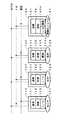
図11は、従来のフロント電装システムの一構成例を示す回路図である。フロントECU(Electronic Control Unit)100には、バッテリから電源を供給するための電源線、CAN(Controller Area Network)等のプロコトルで通信される車内LAN(Local Area Network)と接続するメイン多重線、各種のフロント補機、リア補機、センサ類、及びスイッチ類が接続される。
【0003】
フロントECU100には、フロント補機として、ヘッドランプ154RH、154LH、サイドマーカランプ184RH、184LH、クリアランスランプ174aRH、174aLH、フロントフォグランプ164RH、164LH、コーナリングランプ174bRH、174bLH、ホーン104aHI、104bLO、及びフロントウォッシャモータ194bがワイヤーハーネスにより接続される。また、リア補機としてリアウォッシャモータ254がワイヤーハーネスにより接続される。さらに、フロントECU100には、ホーンスイッチ104e、フードカーテシスイッチ104f、ウォッシャレベルセンサ194a、及びヘッドランプクリーナリレー104cがワイヤーハーネスにより接続される。
【0004】
フロントECU100は、内部に図示しないCPU、スイッチ及びセンサ類から入力される信号を当該CPUに取り込むための入力インタフェース、ヘッドランプクリーナリレー104cに信号を出力するための出力インタフェース、並びに各種の補機に搭載されているランプ、モータ及びホーンを駆動するためのデバイス(半導体スイッチやメカリレー)を搭載している。
【0005】
本発明に関連する従来技術として、本出願人は、特許文献1に車両の形態が違っていても基本となる主制御装置の共通化を図ることができると共にコストの削減が可能なオプション用LAN接続ワイヤーハーネスを開示している。特許文献1は、サブECUからゲートワイヤーハーネスを介して車両電装品を制御している。
【0006】
【特許文献1】
特開2001−287605号公報
【0007】
【発明が解決しようとする課題】
図11に示した従来のフロント電装システムでは、そのフロントECUから各補機への駆動信号を夫々ワイヤーハーネスにより当該補機に伝達し、各種センサ及びスイッチ類からの信号も夫々ワイヤハーネスにより入力されるため、フロントECUのコネクタ極数が多くなり、ワイヤハーネスの本数も多かった。
【0008】
したがって、フロント補機の仕様・機能が変更になると、フロントECUに接続しているワイヤーハーネスの変更が必要になり、ワイヤーハーネスの品種・品番も増加した。特に、フロント補機の機能が増加すると、回路数が増加し、ワイヤーハーネスも肥大化し、質量増を招いた。同時に、フロントECUも肥大化し、質量増(燃費・走行性能の悪化)、及び搭載性の悪化を招き、フロントECUに搭載されるソフトウェアも、肥大化した。これらにより、フロントECU品番が増加し、延いては開発工数の増加、仕様追加・変更工数増加につながった。
【0009】
また、フロントECUに多数の負荷駆動デバイス(半導体スイッチまたはメカリレー)が搭載されているため、その小型化が難しく、発熱の問題も発生した。
【0010】
さらに、補機内のランプやモータ等をPWM(Pulse Width Modulation)制御で駆動した場合、そのランプやモータへのワイヤハーネスからノイズが発生するという問題もあった。例えば、ラジオのアンテナケーブル等に悪影響を及ぼしていた。
【0011】
この点、特許文献1は、サブECUを設けることにより、これらの問題を改善している。本発明は、特許文献1をより発展させ、上記問題点を抜本的に解決する技術を開示する。
【0012】
即ち、本発明の目的は、フロントECUの機能を分散して個々の機能に標準化し、また、ワイヤーハーネスの簡素化・省線化・軽量化、フロントECUの簡素化・小型化・軽量化、及びフロントECUの低発熱化を大幅に実現することができるフロント電装システム、フロント電装システム用電子制御ユニット及び電装コネクタを提供することである。
【0013】
また本発明の目的は、フロント補機の機能変更(仕向・グレード等の仕様差)への対応が極めて容易に行うことができるフロント電装システム、フロント電装システム用電子制御ユニット及び電装コネクタを提供することである。
【0014】
さらに本発明の目的は、フロントECUからフロント補機へのワイヤーハーネスから発生するノイズを大幅に低減することができるフロント電装システム、フロント電装システム用電子制御ユニット及び電装コネクタを提供することである。
【0015】
【課題を解決するための手段】
かかる目的を達成するために、請求項1記載の発明にかかるフロント電装システムは、車両のフロントに設けられるランプ等の負荷系電子部品(例えば、図1の実施形態のヘッドランプ154RH、154LH、フロントフォグランプ164RH、164LH、サイドマーカランプ184RH、184LH、リアウォッシャ254に対応する。)と、該負荷系電子部品がコネクタ接続された負荷用電装コネクタ(例えば、図1の実施形態のヘッドランプ用電装コネクタ150RH、150LH、フロントフォグランプ用電装コネクタ160RH、160LH、サイドマーカランプ用電装コネクタ180RH、180LH、リアウォッシャ用電装コネクタ250に対応する。)と、前記車両のメインバスライン(例えば、図1、図2の実施形態のメイン多重線(符号なし)に対応する。)に接続され、前記メインバスラインの通信プロトコルにより前記メインバスラインに接続された他の電子制御ユニットとの間で送受信を行うメイン送受信手段(例えば、図2の実施形態のメイン多重線送受信回路106に対応する。)と、前記負荷用電装コネクタがワイヤハーネス(例えば、図9及び図10の実施形態のワイヤーハーネス(符号なし)に対応する。)を介してコネクタ接続されるサブバスライン(例えば、図2の実施形態のフロントECU内の電源ライン(符号なし)に対応する。)と、該サブバスラインにコネクタ接続された前記負荷用電装コネクタとの間で前記サブバスラインの通信プロトコルにより送受信を行うサブ送受信手段(例えば、図2の実施形態の制御IC107が備える電源重畳多重送信回路、及び電源重畳多重受信回路(符号なし)に対応する。)と、前記メイン送受信手段が前記メインバスラインから受信した前記負荷用電装コネクタにコネクタ接続されている前記負荷系電子部品の駆動/非駆動を指示する制御信号を、前記サブバスラインの通信プロトコルに変換した上で、前記サブ送受信手段から前記サブバスラインに送信させる制御手段(例えば、図2の実施形態のCPU108に対応する。)とを有するフロント電子制御ユニット(例えば、図1、図2の実施形態のフロントECU100に対応する。)とを備え、前記負荷用電装コネクタが、前記サブバスラインの通信プロトコルにより前記フロント電子制御ユニットとの間で送受信を行うコネクタ送受信手段(例えば、図6、図7の実施形態の送信回路131a、受信回路131bに対応する。)と、該コネクタ送受信手段により受信した前記制御信号を駆動信号に変換して該駆動信号に基づいて前記負荷系電子部品を駆動する駆動制御手段(例えば、図6、図7の実施形態のマイコン132aに対応する。)とを有することを特徴としている。
また、請求項10記載の発明にかかるフロント電装システム用電子制御ユニット(例えば、図1、図2の実施形態のフロントECU100に対応する。)は、車両のメインバスライン(例えば、図1、図2の実施形態のメイン多重線(符号なし)に対応する。)に接続され、前記メインバスラインの通信プロトコルにより前記メインバスラインに接続された他の電子制御ユニットとの間で送受信を行うメイン送受信手段(例えば、図2の実施形態のメイン多重線送受信回路106に対応する。)と、車両のフロントに設けられるランプ等の負荷系電子部品(例えば、図1の実施形態のヘッドランプ154RH、154LH、フロントフォグランプ164RH、164LH、サイドマーカランプ184RH、184LH、リアウォッシャ254に対応する。)がコネクタ接続された電装コネクタ(例えば、図1の実施形態のヘッドランプ用電装コネクタ150RH、150LH、フロントフォグランプ用電装コネクタ160RH、160LH、サイドマーカランプ用電装コネクタ180RH、180LH、リアウォッシャ用電装コネクタ250に対応する。)がワイヤハーネス(例えば、図9及び図10の実施形態のワイヤーハーネス(符号なし)に対応する。)を介してコネクタ接続されるサブバスライン(例えば、図2の実施形態のフロントECU内の電源ライン(符号なし)に対応する。)と、該サブバスラインにコネクタ接続された前記電装コネクタとの間で前記サブバスラインの通信プロトコルにより送受信を行うサブ送受信手段(例えば、図2の実施形態の制御IC107が備える電源重畳多重送信回路、及び電源重畳多重受信回路(符号なし)に対応する。)と、前記メイン送受信手段が前記メインバスラインから受信した前記負荷系電子部品の駆動/非駆動を指示する制御信号を、前記サブバスラインの通信プロトコルに変換した上で、前記サブ送受信手段から前記サブバスラインに送信させる制御手段(例えば、図2の実施形態のCPU108に対応する。)とを備え、前記サブ送受信手段から前記サブバスラインに送信した前記制御信号を前記電装コネクタで受信させ、前記受信した制御信号を駆動信号に変換して該駆動信号に基づいて前記負荷系電子部品を駆動させるようにしたことを特徴としている。
さらに、請求項12記載の発明にかかる電装コネクタ(例えば、図1の実施形態のヘッドランプ用電装コネクタ150RH、150LH、フロントフォグランプ用電装コネクタ160RH、160LH、サイドマーカランプ用電装コネクタ180RH、180LH、リアウォッシャ用電装コネクタ250に対応する。)は、車両のメインバスライン(例えば、図1、図2の実施形態のメイン多重線(符号なし)に対応する。)に接続され、前記メインバスラインの通信プロトコルにより前記メインバスラインに接続された他の電子制御ユニットとの間で送受信を行うメイン送受信手段(例えば、図2の実施形態のメイン多重線送受信回路106に対応する。)と、サブバスライン(例えば、図2の実施形態のフロントECU内の電源ライン(符号なし)に対応する。)と、該サブバスラインの通信プロトコルにより送受信を行うサブ送受信手段(例えば、図2の実施形態の制御IC107が備える電源重畳多重送信回路、及び電源重畳多重受信回路(符号なし)に対応する。)と、前記メイン送受信手段が前記メインバスラインから受信した車両のフロントに設けられるランプ等の負荷系電子部品(例えば、図1の実施形態のヘッドランプ154RH、154LH、フロントフォグランプ164RH、164LH、サイドマーカランプ184RH、184LH、リアウォッシャ254に対応する。)の駆動/非駆動を指示する制御信号を、前記サブバスラインの通信プロトコルに変換した上で、前記サブ送受信手段から前記サブバスラインに送信させる制御手段(例えば、図2の実施形態のCPU108に対応する。)とを備えるフロント電装システム用電子制御ユニット(例えば、図1、図2の実施形態のフロントECU100に対応する。)の前記サブバスラインにワイヤハーネス(例えば、図9及び図10の実施形態のワイヤーハーネス(符号なし)に対応する。)を介してコネクタ接続されるとともに前記負荷系電子部品がコネクタ接続され、前記サブバスラインの通信プロトコルにより前記フロント電子制御ユニットとの間で送受信を行うコネクタ送受信手段(例えば、図6、図7の実施形態の送信回路131a、受信回路131bに対応する。)と、該コネクタ送受信手段により受信した前記制御信号を駆動信号に変換して該駆動信号に基づいて前記負荷系電子部品を駆動する駆動制御手段(例えば、図6、図7の実施形態のマイコン132aに対応する。)とを有することを特徴としている。
【0016】
したがって、請求項1、10又は12記載の発明によれば、フロント電子制御ユニットからサブバスラインにワイヤハーネスを介してコネクタ接続された負荷用電装コネクタが受信した制御信号を基に、負荷用電装コネクタにコネクタ接続されている負荷系電子部品を負荷用電装コネクタが有する駆動制御手段で駆動することにより、従来の集中制御を行うフロントECU(電子制御ユニット)の機能を分散して個々の機能に標準化することができる。したがって、フロント関連の負荷電装品の増加・高機能化に対して、負荷用電装コネクタが有する駆動制御手段がそれらの変化を吸収することができ、他の負荷用電装コネクタが有する駆動制御手段、フロント電子制御ユニット及びワイヤーハーネスへの影響を最小限にすることができる。また、従来フロントECUに内蔵されていた駆動制御手段を、負荷用電装コネクタに移したことにより、フロントECUの簡素化・小型化・軽量化を実現し、発熱も抑えることができる。さらに、フロント電子制御ユニット100が、制御信号のプロトコル変換を行って負荷用電装コネクタに変換後の制御信号を送信することにより、メインバスラインとサブバスラインによる階層型ネットワークを構築することができる。例えば、メインバスラインにハイスペックな伝送媒体を用い、サブバスラインに低コストな伝送媒体を使用することにより、必要な通信速度を確保しながら低コスト化することができる。さらにまた、例えば、負荷系電子部品をPWM駆動する場合に、駆動制御手段から駆動することにより、ノイズの発生を最小限にすることができる。負荷用電装コネクタが有する駆動制御手段がコネクタ接続されている負荷系電子部品を直近から駆動することができることにより、上記効果を最大限に発揮させることができる。
【0017】
請求項2記載の発明にかかるフロント電装システムは、請求項1記載の発明において、車両のフロントに設けられるランプ等の複数の負荷系電子部品(例えば、図1の実施形態のクリアランスランプ174aRH、174aLH、コーナリングランプ174bRH、174bLHに対応する。)を種々組み合わせて構成された第1の補機モジュール(例えば、図1の実施形態の補機モジュール174RH、174LHに対応する。)がコネクタ接続された第1のモジュール用電装コネクタ(例えば、図1の実施形態の補機モジュール174RH、174LH用電装コネクタ170RH、170LHに対応する。)をさらに備え、前記第1のモジュール用電装コネクタが、前記サブバスラインの通信プロトコルにより前記フロント電子制御ユニットとの間で送受信を行うコネクタ送受信手段(例えば、図6、図7の実施形態の送信回路131a、受信回路131bに対応する。)と、該コネクタ送受信手段により受信した前記制御信号を駆動信号に変換して該駆動信号に基づいて前記複数の負荷系電子部品を駆動する駆動制御手段(例えば、図6、図7の実施形態のマイコン132aに対応する。)とを有し、前記フロント電子制御ユニットの前記サブ送受信手段が、前記サブバスラインにコネクタ接続された前記第1のモジュール用電装コネクタとの間で前記サブバスラインの通信プロトコルにより送受信を行い、前記フロント電子制御ユニットの前記制御手段が、前記メイン送受信手段が前記メインバスラインから受信した前記第1のモジュール用電装コネクタの前記負荷系電子部品の駆動/非駆動を指示する制御信号を、前記サブバスラインの通信プロトコルに変換した上で、前記サブ送受信手段から前記サブバスラインに送信させ、前記第1のモジュール用電装コネクタの前記駆動制御手段が、前記コネクタ送受信手段により受信した前記制御信号を駆動信号に変換して該駆動信号に基づいて前記第1の補機モジュールの前記複数の負荷系電子部品を駆動することを特徴としている。
【0018】
したがって、請求項2記載の発明によれば、モジュール化した複数の負荷系電子部品を、一つの電装コネクタに搭載された一つの駆動制御手段で駆動することにより、さらにワイヤーハーネスを簡素化・省線化・軽量化することができる。また、フロントECUのコネクタ端子数も削減することができる。
【0019】
請求項3記載の発明にかかるフロント電装システムは、請求項1または2記載の発明において、車両のフロントに設けられるランプ等の負荷系電子部品(例えば、図1の実施形態のフロントウォッシャモータ194bに対応する。)及びセンサ(例えば、図1の実施形態のウォッシャレベルセンサ194aに対応する。)で構成された第2の補機モジュール(例えば、図1の実施形態のフロントウォッシャモジュール194に対応する。)がコネクタ接続された第2のモジュール用電装コネクタ(例えば、図1の実施形態のフロントウォッシャモジュール194用電装コネクタ190に対応する。)をさらに備え、前記第2のモジュール用電装コネクタが、前記サブバスラインの通信プロトコルにより前記フロント電子制御ユニットとの間で送受信を行うコネクタ送受信手段(例えば、図6、図7の実施形態の送信回路131a、受信回路131bに対応する。)と、該コネクタ送受信手段により受信した前記制御信号を駆動信号に変換して該駆動信号に基づいて前記負荷系電子部品を駆動する駆動制御手段(例えば、図6、図7の実施形態のマイコン132aに対応する。)とを有し、前記フロント電子制御ユニットの前記サブ送受信手段が、前記サブバスラインに接続された前記第2のモジュール用電装コネクタとの間で前記サブバスラインの通信プロトコルにより送受信を行い、前記フロント電子制御ユニットの前記制御手段が、前記メイン送受信手段が前記メインバスラインから受信した前記第2のモジュール用電装コネクタに接続されている前記負荷系電子部品の駆動/非駆動を指示する制御信号を、前記サブバスラインの通信プロトコルに変換した上で、前記サブ送受信手段から前記サブバスラインに送信させ、前記第2のモジュール用電装コネクタの前記駆動制御手段が、前記コネクタ送受信手段により受信した前記制御信号を駆動信号に変換して該駆動信号に基づいて前記第2の補機モジュールの前記複数の負荷系電子部品を駆動し、前記第2のモジュール用電装コネクタは、前記センサからのセンサ信号を前記サブバスラインの通信プロトコルに変換した上で、前記コネクタ送受信手段から前記サブバスラインに送信し、前記フロント電子制御ユニットの前記制御手段が、前記サブ送受信手段により前記サブバスラインから受信した前記センサ信号を前記メインバスラインの通信プロトコルに変換した上で、前記メイン送受信手段から前記メインバスラインに送信させることを特徴としている。
また、請求項11記載の発明にかかるフロント電装システム用電子制御ユニットは、請求項10記載の発明において、前記サブバスラインには、負荷系電子部品(例えば、図1の実施形態のフロントウォッシャモータ194bに対応する。)及びセンサ(例えば、図1の実施形態のウォッシャレベルセンサ194aに対応する。)で構成された第2の補機モジュール(例えば、図1の実施形態のフロントウォッシャモジュール194に対応する。)がコネクタされた第2のモジュール用電装コネクタ(例えば、図1の実施形態のフロントウォッシャモジュール194用電装コネクタ190に対応する。)がコネクタ接続され、前記サブ送受信手段は、前記サブバスラインに接続された前記第2のモジュール用電装コネクタとの間で前記サブバスラインの通信プロトコルにより送受信を行い、前記制御手段は、前記メイン送受信手段が前記メインバスラインから受信した前記第2の補機モジュールの前記負荷系電子部品の駆動/非駆動を指示する制御信号を、前記サブバスラインの通信プロトコルに変換した上で、前記サブ送受信手段から前記サブバスラインに送信させ、前記サブ送受信手段から前記サブバスラインに送信した前記制御信号を前記第2のモジュール用電装コネクタで受信させ、前記受信した制御信号を駆動信号に変換して該駆動信号に基づいて前記第2の補機モジュールの前記負荷系電子部品を駆動させ、前記サブ送受信手段は、前記サブバスラインの通信プロトコルに変換した上で前記サブバスラインに送信される前記第2のモジュール用電装コネクタの前記センサからのセンサ信号を前記サブバスラインから受信し、前記制御手段は、前記受信した前記センサ信号を前記メインバスラインの通信プロトコルに変換した上で、前記メイン送受信手段から前記メインバスラインに送信させることを特徴としている。
【0020】
したがって、請求項3または11記載の発明によれば、負荷系電子部品及びセンサをモジュール化した第2の補機モジュールに結合した第2のモジュール用電装コネクタに搭載された一つの駆動制御手段で駆動及び監視することにより、ワイヤーハーネスを簡素化・省線化・軽量化することができる。また、フロントECUのコネクタ端子数も削減することができる。
【0021】
請求項4記載の発明にかかるフロント電装システムは、請求項2または3記載の発明において、車両のフロントに設けられるランプ等の複数の負荷系電子部品(例えば、図1の実施形態のクリアランスランプ174aRH、174aLH、コーナリングランプ174bRH、174bLHに対応する。)を種々組み合わせて構成された第1の補機モジュール(例えば、図1の実施形態の補機モジュール174RH、174LHに対応する。)をさらに備え、前記第1の補機モジュールが、前記サブバスラインの通信プロトコルにより前記フロント電子制御ユニットとの間で送受信を行うモジュール送受信手段(例えば、図6、図7の実施形態の送信回路131a、受信回路131bに対応する。)と、該モジュール送受信手段により受信した前記制御信号を駆動信号に変換して該駆動信号に基づいて前記負荷系電子部品を駆動する駆動制御手段(例えば、図6、図7の実施形態のマイコン132aに対応する。)とを有し、前記フロント電子制御ユニットの前記サブ送受信手段が、前記サブバスラインに接続された前記第1の補機モジュールとの間で前記サブバスラインの通信プロトコルにより送受信を行い、前記フロント電子制御ユニットの前記制御手段が、前記メイン送受信手段が前記メインバスラインから受信した前記第1の補機モジュールの前記負荷系電子部品の駆動/非駆動を指示する制御信号を、前記サブバスラインの通信プロトコルに変換した上で、前記サブ送受信手段から前記サブバスラインに送信させ、前記第1の補機モジュールの前記駆動制御手段が、前記モジュール送受信手段により受信した前記制御信号を駆動信号に変換して該駆動信号に基づいて前記第1の補機モジュールの前記負荷系電子部品を駆動することを特徴としている。
【0022】
したがって、請求項4記載の発明によれば、複数の負荷系電子部品をモジュール化した第1の補機モジュールに一つの駆動制御手段を搭載して、複数の負荷系電子部品を駆動することにより、さらにワイヤーハーネスを簡素化・省線化・軽量化することができる。また、フロントECUのコネクタ端子数も削減することができる。
【0023】
請求項5記載の発明にかかるフロント電装システムは、請求項1または2記載の発明において、車両のフロントに設けられるランプ等の負荷系電子部品(例えば、図1の実施形態のフロントウォッシャモータ194bに対応する。)及びセンサ(例えば、図1の実施形態のウォッシャレベルセンサ194aに対応する。)で構成された第2の補機モジュール(例えば、図1の実施形態のフロントウォッシャモジュール194に対応する。)をさらに備え、前記第2の補機モジュールが、前記サブバスラインの通信プロトコルにより前記フロント電子制御ユニットとの間で送受信を行うモジュール送受信手段(例えば、図6、図7の実施形態の送信回路131a、受信回路131bに対応する。)と、該モジュール送受信手段により受信した前記制御信号を駆動信号に変換して該駆動信号に基づいて前記負荷系電子部品を駆動する駆動制御手段(例えば、図6、図7の実施形態のマイコン132aに対応する。)とを有し、前記フロント電子制御ユニットの前記サブ送受信手段が、前記サブバスラインに接続された前記第2の補機モジュールとの間で前記サブバスラインの通信プロトコルにより送受信を行い、前記フロント電子制御ユニットの前記制御手段が、前記メイン送受信手段が前記メインバスラインから受信した前記第2の補機モジュールの前記負荷系電子部品の駆動/非駆動を指示する制御信号を、前記サブバスラインの通信プロトコルに変換した上で、前記サブ送受信手段から前記サブバスラインに送信させ、前記第2の補機モジュールの前記駆動制御手段が、前記ジュール送受信手段により受信した前記制御信号を駆動信号に変換して該駆動信号に基づいて前記第2の補機モジュールの前記負荷系電子部品を駆動し、前記第2の補機モジュールは、前記センサからのセンサ信号を前記サブバスラインの通信プロトコルに変換した上で、前記ジュール送受信手段から前記サブバスラインに送信し、前記フロント電子制御ユニットの前記制御手段が、前記サブ送受信手段により前記サブバスラインから受信した前記センサ信号を前記メインバスラインの通信プロトコルに変換した上で、前記メイン送受信手段から前記メインバスラインに送信させることを特徴としている。
【0024】
したがって、請求項5記載の発明によれば、負荷系電子部品及びセンサをモジュール化した第2の補機モジュールに一つの駆動制御手段を搭載して、負荷系電子部品及びセンサを駆動及び監視することにより、さらにワイヤーハーネスを簡素化・省線化・軽量化することができる。また、フロントECUのコネクタ端子数も削減することができる。
【0025】
請求項6記載の発明にかかるフロント電装システムは、請求項2または4記載の発明において、前記第1の補機モジュールの前記負荷系電子部品は、クリアランスランプ、及びコーナリングランプであることを特徴としている。
【0026】
したがって、請求項6記載の発明によれば、クリアランスランプ及びコーナリングランプをモジュール化することにより、ワイヤーハーネスを簡素化・省線化・軽量化することができる。また、フロントECUのコネクタ端子数も削減することができる。
【0027】
請求項7記載の発明にかかるフロント電装システムは、請求項3または5記載の発明において、前記第2の補機モジュールの前記負荷系電子部品は、フロントウォッシャモータであり、前記センサは、ウォッシャレベルセンサであることを特徴としている。
【0028】
したがって、請求項7記載の発明によれば、フロントウォッシャモータ及びウォッシャレベルセンサをモジュール化することにより、ワイヤーハーネスを簡素化・省線化・軽量化することができる。また、フロントECUのコネクタ端子数も削減することができる。
【0029】
請求項8記載の発明にかかるフロント電装システムは、請求項1〜3の何れかに記載の発明において、前記電装コネクタと前記フロント電子制御ユニットとは、一端が前記フロント電子制御ユニット内の前記サブバスライン、電源ライン及びアースライン(例えば図2の実施形態のフロントECU内の通信ライン(図示なし)、電源ライン及びアースライン(図示なし)に対応する。)にそれぞれコネクタ接続され、他端が前記電装コネクタ内の前記送受信手段に接続された通信ライン、電源ライン及びアースライン(例えば図8の実施形態の電装コネクタ内の通信ライン(図示なし)、電源ライン及びアースライン(図示なし)に対応する。)にそれぞれコネクタ接続される通信線、電源線及びGND線とからなるワイヤハーネス、又は、一端が前記フロント電子制御ユニット内の電源ラインで形成された前記サブバスライン及びアースライン(例えば図2の実施形態のフロントECU内の電源ライン及びアースライン(図示なし)に対応する。)にそれぞれコネクタ接続され、他端が前記電装コネクタ内の前記送受信手段に接続された通信ラインを兼ねた電源ライン及びアースライン(例えば図8の実施形態の電装コネクタ内の電源ライン及びアースライン(図示なし)に対応する。)にそれぞれコネクタ接続される通信線を兼ねた電源線とGND線とからなるワイヤハーネスを介して相互に接続されていることを特徴としている。
【0030】
したがって、請求項8記載の発明によれば、フロント電子制御ユニットと電装コネクタとが信号線、電源線及びGND線とからなるワイヤハーネス、又は、通信線を兼ねた電源線とGND線とからなるワイヤハーネスを介してコネクタ接続されており、ワイヤーハーネスを簡素化・省線化・軽量化することができる。また、フロントECUのコネクタ端子数も削減することができる。
【0031】
請求項9記載の発明にかかるフロント電装システムは、請求項4または5に記載の発明において、前記補機モジュールと前記フロント電子制御ユニットとは、一端が前記フロント電子制御ユニット内の前記サブバスライン、電源ライン及びアースライン(例えば図2の実施形態のフロントECU内の電源ライン及びアースライン(図示なし)に対応する。)にそれぞれコネクタ接続され、他端が前記補機モジュール内の前記送受信手段に接続された通信ライン、電源ライン及びアースライン(例えば図8の実施形態の電装コネクタ内の通信ライン(図示なし)、電源ライン及びアースライン(図示なし)に対応する。)にそれぞれコネクタ接続される通信線、電源線及びGND線とからなるワイヤハーネス、又は、一端が前記フロント電子制御ユニット内の電源ラインで形成された前記サブバスライン及びアースライン(例えば図2の実施形態のフロントECU内の電源ライン及びアースライン(図示なし)に対応する。)にそれぞれコネクタ接続され、他端が前記補機モジュール内の前記送受信手段に接続された通信ラインを兼ねた電源ライン及びアースライン(例えば図8の実施形態の電装コネクタ内の電源ライン及びアースライン(図示なし)に対応する。)にそれぞれコネクタ接続される通信線を兼ねた電源線とGND線とからなるワイヤハーネスを介して相互に接続されていることを特徴としている。
【0032】
したがって、請求項9記載の発明によれば、フロント電子制御ユニットと補機モジュールとが、通信線、電源線及びGND線とからなるワイヤハーネス、又は、通信線を兼ねた電源線とGND線とからなるワイヤハーネスを介してコネクタ接続されており、ワイヤーハーネスを簡素化・省線化・軽量化することができる。また、フロントECUのコネクタ端子数も削減することができる。
【0033】
【発明の実施の形態】
以下、本発明の実施形態を添付図面を参照しながら詳細に説明する。
図3は、本発明の実施形態における電装コネクタの基本概念を示す機能ブロック図である。センサ114のコネクタに直接接続する電装コネクタ110は、内蔵している電子基板上に通信部111、制御部112、及びI/O部113を備えている。スイッチSW124に直接接続する電装コネクタ120も、内蔵している電子基板上に通信部121、制御部122、及びI/O部123を備えている。負荷(ランプ、モータ等)134に直接接続する電装コネクタ130は、内蔵している電子基板上に通信部131、制御部132、及び駆動部133を備えている。補機モジュール144に直接接続する電装コネクタ140は、内蔵している電子基板上に通信部141、制御部142、I/O部143a、及び駆動部143bを備えている。
【0034】
補機モジュール144は、車両の基本機能以外の機能を実現する補機(例えば、フロントウォッシャ等)をモジュール化したものであり、複数の電子部品により構成される。例えば、フロントウォッシャを実現する補機モジュールは、少なくともモータ、センサを備える。また、補機モジュール144は、コーナリングランプとクリアランスランプといったように複数の補機をモジュール化したものでもよい。当該補機モジュールは、少なくとも二つのランプを備える。
【0035】
このように、補機モジュール144は、複数の電子部品(モータ、ランプ、ホーン、ヒータ、スイッチ、センサ等)を種々組み合わせて構成される。これらの電子部品の内、スイッチ及びセンサ類は、電装コネクタ140のI/O部143aと接続され、制御部142により監視される。また、上記電子部品の内、モータ、ランプ等の負荷は、電装コネクタ140の駆動部143bと接続され、駆動される。ここで、電装コネクタ140のI/O部143aは、補機モジュール144内にセンサやスイッチ類が存在しない場合は必要ない。
【0036】
各電装コネクタの通信部111〜141は、他の電装コネクタ、ECU、または他のシステムと通信するために、通信線または電源線を利用して制御信号のやり取りを行う。通信プロトコルは、LIN(Local Interconnect Network)等を使用するとよい。また、LINからゲートウェイ装置を介してCAN(Control Area Network)上の機器、及びその先のLIN上の機器と通信することも可能である。
【0037】
制御部112は、負荷134の状態を監視しているセンサや温度センサ等のセンサ114のセンサ信号をI/O部113を介して受信する。制御部112は、受信したセンサ信号に、送信すべき他の電装コネクタ、ECU、または他のシステムの機器のアドレスを付す等の加工を施し、制御信号として通信部111に出力する。
【0038】
制御部122は、ユーザによりスイッチSW124がON/OFFされると、そのON/OFF信号をI/O部123を介して受信する。制御部122は、受信したON/OFF信号に、送信すべき他の電装コネクタ、ECU、または他のシステムの機器のアドレスを付す等の加工を施し、制御信号として通信部121に出力する。
【0039】
制御部132は、通信部131を介して他の電装コネクタ、ECU、または他のシステムの機器から負荷134を駆動するための制御信号を受信する。制御部132は、受信した制御信号に基づき、負荷134を駆動するための駆動部133を制御する。駆動部133は、MOSFET等の半導体素子によりランプやモータやホーン等の負荷134を駆動する。また、モータの速度を調整するといった、負荷134のPWM制御も可能である。
【0040】
制御部142は、補機モジュール144内に、センサやスイッチが存在するときはI/O部143aを介してセンサ信号やON/OFF信号を受信する。制御部142は、受信したセンサ信号やON/OFF信号が同一補機モジュール144内の負荷用の信号であれば、駆動部143bに指示して当該負荷を駆動する。また、受信したセンサ信号やON/OFF信号が同一補機モジュール144内に存在しない負荷用の信号であれば、受信したセンサやON/OFF信号に、送信すべき他の電装コネクタ、ECU、または他のシステムの機器のアドレスを付す等の加工を施し、制御信号として通信部141に出力する。
【0041】
また、制御部142は、補機モジュール144内に負荷が存在するときは通信部141を介して他の電装コネクタ、ECU、または他のシステムの機器から負荷を駆動するための制御信号を受信する。制御部142は、受信した制御信号に基づき、当該負荷を駆動するための駆動部143bを制御する。
【0042】
夫々の電装コネクタ110〜140は、電源線(バッテリーライン+B)、GND線と接続している。電装コネクタ110〜140は、センサ114、スイッチSW124、負荷134、及び補機モジュール144と直接接続しているため、電源とアースのジョイントを電装コネクタ110〜140の内蔵している電子基板で吸収している。夫々の電装コネクタ110〜140の通信部111〜141は、通信線と接続している。ここで、通信に電源重畳多重方式を採用した場合は、通信線は必要ない。その場合、通信部111〜141は、電源線と接続する。
【0043】
ここで、電源重畳多重方式について説明すると、電源重畳多重方式とは、電源線に通信を重畳させることで専用通信線なしで信号を伝送する方式である。図4は、電源重畳多重方式を採用した場合の通信部111の内部構成を示すブロック図である。当該通信部111は、送信回路111a、受信回路111b、及び重畳回路111cを備える。送信回路111a、受信回路111bは、コネクタ送受信手段を構成している。
【0044】
送信回路111aは、制御部112から入力されたパルス状の送信データを、例えばASK(Amplitude Shift Keying)変調して、重畳回路111cに出力する。重畳回路111cは、送信回路111aから入力された変調後の信号を電源線に重畳する。また、重畳回路111cは、電源線に重畳された通信信号を分離して、受信回路111bに出力する。受信回路111bは、重畳回路111cから入力された信号を復調し、パルス状のディジタル信号を受信データとして制御部112に出力する。
【0045】
図5は、本発明の実施形態における補機モジュールの基本概念を示す機能ブロック図である。本実施形態における補機モジュール150は、内蔵している電子基板上に、通信部151、制御部152、I/O部153a、及び駆動部153bを備えている。補機モジュール150は、電源線(バッテリーライン+B)、GND線と接続している。補機モジュール150の通信部151は、通信線と接続している。ここで、通信に電源重畳多重方式を採用した場合は、この通信線は必要ない。
【0046】
なお、補機モジュール150に内蔵されている電子基板上の通信部151、制御部152、I/O部153a、及び駆動部153bの機能は、電装コネクタ140に内蔵されているそれらの機能と同様であるため、説明を省略する。
【0047】
図6は、本発明の実施形態における電装コネクタまたは補機モジュールに内蔵される電子基板上の回路構成(通信線方式)の一例を示す図である。負荷134がモータ134aである場合に、モータ134aに直接接続する電装コネクタの例を説明する。回路構成は、送信回路131a、受信回路131b、マイコン132a、制御IC132b、及びMOS型電界効果トランジスタ(MOS1〜4)から構成されるHブリッジ回路133を備える。なお、送信回路131a、受信回路131bは、回路構成が電装コネクタの場合、コネクタ送受信手段を、補機モジュールの場合、モジュール送受信手段をそれぞれ構成する。
【0048】
バッテリ電源を供給する電源線は、制御IC132b、Hブリッジ回路133にバッテリ電源を供給している。送信回路131aは、マイコン132aから入力されたパルス状のディジタル信号を変調して通信線に送出する。受信回路131bは、通信線から自己宛ての制御信号を受信し、復調してマイコン132aに出力する。
【0049】
制御IC132bは、MOS1とMOS3を駆動する図示しないハイサイドMOSドライバ、当該ハイサイドMOSドライバに供給する電圧を昇圧するための図示しないチャージポンプ、MOS2とMOS4を駆動する図示しないローサイドMOSドライバを備えており、モータ134aの正逆転制御を行う。ここで、図中の制御IC132bに送信回路131a、受信回路131bを組み込んでIC化してもよいし、さらに、マイコン132aを組み込んでIC化してもよい。
【0050】
マイコン132aは、受信回路131bから入力された制御信号を解読して、上記ハイサイドMOSドライバ、上記ローサイドMOSドライバに制御信号を出力する。また、マイコン132aは、他の電装コネクタやECUに制御信号を送信する必要がある場合は、当該制御信号を送信回路131aに出力する。
【0051】
Hブリッジ回路133を構成するMOS1及びMOS4がON、MOS2及びMOS3がOFFのとき、モータ134aが正転する。MOS2及びMOS3がON、MOS1及びMOS4がOFFのとき、モータ134aが逆転する。したがって、上記ハイサイドMOSドライバは、モータ134aを正転させる場合は、MOS1をONし、MOS3をOFFする。モータ134aを逆転させる場合は、MOS1をOFFし、MOS3をONする。上記ローサイドMOSドライバは、モータ134aを正転させる場合は、MOS2をOFFし、MOS4をONする。モータ134aを逆転させる場合は、MOS2をONし、MOS4をOFFする。
【0052】
モータ134aの速度制御が必要な場合は、制御IC132b内に図示しないPWM制御回路を設ける。当該PWM制御回路は、上記ハイサイドMOSドライバ及び上記ローサイドMOSドライバの前段に設けられ、任意のデューティ比のPWM波形を上記ハイサイドMOSドライバ及び上記ローサイドMOSドライバに出力する。
【0053】
図7は、本発明の実施形態における電装コネクタまたは補機モジュールに内蔵される電子基板上の回路構成(電源重畳多重方式)の一例を示す図である。図7に示す電装コネクタは、送信回路131a、受信回路131b、フィルタ131d、マイコン132a、制御IC132b、及びMOS型電界効果トランジスタ(MOS1〜4)から構成されるHブリッジ回路133を備える。
【0054】
フィルタ131dは、電源線に重畳されている制御信号を搬送している帯域をフィルタリングするバンドパスフィルタである。フィルタ131dは、フィルタリングした帯域の信号を受信回路131bに出力する。その他の要素は、通信線方式の場合と同様であるため、説明を省略する。
【0055】
図8は、本発明の実施形態における電装コネクタまたは補機モジュールに内蔵される電子基板上の回路構成(電源重畳多重方式)の一例を示す図である。負荷134がランプ134bである場合に、ランプ134bに直接接続する電装コネクタの例を説明する。図8に示す電装コネクタは、制御IC132c、フィルタ131e、MOS型電界効果トランジスタMOS5、及び断線検出回路132dを備える。
【0056】
フロントECU100から直接、または他の電装コネクタを介して配索される電源線は、制御IC132c、MOS型電界効果トランジスタMOS5の電源ラインにバッテリ電源を供給している。また、電源線は、図示しないカップリングコンデンサを介してフィルタ131eにも接続され、重畳されている制御信号を制御IC132cに伝達する。電源線は、さらに他の電装コネクタに電源供給、または制御信号伝達を行う必要がある場合は、当該電装コネクタにまで配索される。GND線は、ランプ134b及び制御IC132cのアースラインを、直接、または他の電装コネクタを経由してアースに接続する。
【0057】
制御IC132cは、図示しないレギュレータ(定電圧電源回路)、チャージポンプ、MOSFET駆動ドライバ、マイコン、PWM制御回路、電源重畳多重送信回路、電源重畳多重受信回路を備える。レギュレータは、電源線から供給されるバッテリ電源(例えば12V)を基にロジック電源(例えば5V)を生成し、チャージポンプは、電源線から供給されるバッテリ電源(例えば12V)を、例えば12V+10Vに昇圧する。MOSFET駆動ドライバは、チャージポンプにより昇圧された電圧で、MOS型電界効果トランジスタMOS5を駆動する。
【0058】
マイコンは、レギュレータにより生成されたロジック電源、及び図示しない発振回路の発振周波数により動作し、電源重畳多重受信回路が受信した制御信号を解読して、PWM制御回路に所定のデューティ比を指定する。PWM制御回路は、指定されたデューティ比のゲート駆動用信号を生成する。MOSFET駆動ドライバは、当該ゲート駆動用信号を基に、MOS型電界効果トランジスタMOS5のゲート電極のON/OFF制御を行う。なお、PWM制御回路は、ランプ134bの調光制御等を行わない場合は設けなくてもよい。
【0059】
電源重畳多重送信回路は、マイコンにより生成された制御信号を変調し、電源線に重畳して送信する。例えば、断線等が発生した場合には、ウォーニング信号をフロントECU100を介してメイン多重線に送信する。電源重畳多重受信回路は、電源線から自己宛ての制御信号を受信し、復調してマイコンに出力する。
【0060】
フィルタ131eは、電源線に重畳されている制御信号を搬送している帯域をフィルタリングするバンドパスフィルタである。フィルタ131eは、フィルタリングした帯域の信号を電源重畳受信回路に出力する。
【0061】
MOS型電界効果トランジスタMOS5は、制御IC132c内の図示しないMOSFET駆動ドライバによりゲート電極がON/OFF駆動される。ゲート電極がONで、電源線からのバッテリ電源がランプ134bに供給され、OFFで、ランプ134bへのバッテリ電源の供給が遮断される。なお、MOS型電界効果トランジスタMOS5には、保護回路を設けるとよい。
【0062】
断線検出回路132dは、ランプ134bへ給電する電線の電圧を監視し、所定の閾値電圧と比較し、当該電線に断線が発生したか否かを検知する。検知結果は、制御IC132c内の図示しないマイコンに出力される。
【0063】
なお、ランプ134bに直接接続する電装コネクタの例として、電源重畳多重方式について説明したが、通信線方式でもよいことは、モータ134aに直接接続する電装コネクタの例の説明と同様である。
【0064】
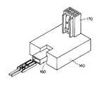
図9は、本発明の実施形態における電装コネクタの概観(通信線方式)を示す斜視図である。当該電装コネクタは、補機モジュール144に接続される電装コネクタ140の一例である。電装コネクタ140は、ソケット160を備え、このソケット160に電源線、GND線、通信線の三本からなり、図示しない一端がフロントECU100のコネクタ端子にコネクタ接続されているワイヤーハーネスの他端のコネクタ(符号なし)が挿入されることで、フロントECU100とワイヤーハーネスを介してコネクタ接続される。電装コネクタ140と補機モジュール144との接続は、電装コネクタ140のソケット170と補機モジュール144が有する図示しないコネクタのピンとの嵌合結合により行われる。図9に示した電装コネクタ140の形状は、一例であり補機モジュール144に合わせて種々の形状がある。電装コネクタ140の内部には、IC(ASIC等)や半導体スイッチング素子を実装した電子基板が内蔵される。
【0065】
図10は、本発明の実施形態における電装コネクタの概観(電源重畳多重方式)を示す斜視図である。電装コネクタ140は、ソケット160を備え、このソケット160に電源線、GND線の二本からなり、図示しない一端がフロントECU100のコネクタ端子にコネクタ接続されているワイヤーハーネスの他端のコネクタ(符号なし)が挿入されることで、フロントECU100とワイヤーハーネスを介してコネクタ接続される。その他の要素は、通信線方式の場合と同様であるため、説明を省略する。従来は補機モジュール144内の個々の電子部品にECUから配索したことから、十本程度の電線からなるワイヤーハーネスを必要としたところでも、本発明の電装コネクタを使用することにより、二本または三本に削減することができる。
【0066】
図1は、本発明の実施形態におけるフロント電装システムの一構成例(電源重畳多重方式)を示す回路図である。当該フロント電装システムは、フロントECU100を備える。フロントECU100には、バッテリから電源を供給するための電源線、CAN等のプロコトルで通信される車内LANを構築しているメイン多重線、各種の補機、及び各種の補機を制御するためのセンサ・スイッチ類が接続される。
【0067】
フロントECU100には、フロント補機としてヘッドランプ154RH、154LH、フロントフォグランプ164RH、164LH、クリアランスランプ174aRH、174aLH、コーナリングランプ174bRH、174bLH、サイドマーカランプ184RH、184LH、ホーン104aHI、104bLO、及びフロントウォッシャモジュール194が接続される。フロントウォッシャモジュール194は、ウォッシャレベルセンサ194a、フロントウォッシャモータ194bを備える。
【0068】
クリアランスランプ174aRHと、コーナリングランプ174bRHは、補機モジュール化されている。左側も同様である。また、フロントECU100には、リア補機としてリアウォッシャ254が接続される。さらに、フロントECU100には、ヘッドランプクリーナリレー104c、ホーンスイッチ104e、及びフードカーテシスイッチ104fが接続されている。ここで、フロントフォグランプ164RH、164LH、サイドマーカランプ184RH、184LH、及びリアウォッシャ254の一部または全部は、仕向けやグレードにより設けなくてもよい。
【0069】
図示しないバッテリまたはオルタネータからの電源を供給し、重畳された多重信号を伝達する電源線は、フロントECU100で分割される。分割された電源線の一つは、ヘッドランプ用電装コネクタ150RH、150LHを介してヘッドランプ154RH、154LHに接続される。さらに、フロントフォグランプ164RH、164LHを設ける場合は、ヘッドランプ用電装コネクタ150RH、150LH、及びフロントフォグランプ用電装コネクタ160RH、160LHを介してフロントフォグランプ164RH、164LHに接続される。
【0070】
フロントECU100で分割された電源線の一つは、補機モジュール174RH、174LH用電装コネクタ170RH、170LH、及び補機モジュール174RH、174LH内のクリアランスランプ174aRH、174aLHを介してコーナリングランプ174bRH、174bLHに接続される。さらに、サイドマーカランプ184RH、184LHを設ける場合は、補機モジュール174RH、174LH用電装コネクタ170RH、170LH、及びサイドマーカランプ用電装コネクタ180RH、180LHを介してサイドマーカランプ184RH、184LHに接続される。
【0071】
フロントECU100で分割された電源線の一つは、フロントウォッシャモジュール194用電装コネクタ190を介してフロントウォッシャモジュール194内のフロントウォッシャモータ194bに接続される。フロントウォッシャモジュール194用電装コネクタ190は、ウォッシャレベルセンサ信号を電源線を介してフロントECU100からメイン多重線へ送信する。さらに、リアウォッシャ254を設ける場合は、フロントウォッシャモジュール194用電装コネクタ190、及びリアウォッシャ用電装コネクタ250を介してリアウォッシャ254に接続される。
【0072】
図2は、本発明の実施形態におけるフロント電装システムのフロントECU100の内部構成(電源重畳多重方式)を示すブロック図である。フロントECU100は、電源重畳多重用フィルタ回路105、メイン送受信手段としてのメイン多重送受信回路(トランシーバ)106、制御IC107、CPU108、半導体リレー109、トランジスタTR、及び入力インタフェースIFを内部に備える。
【0073】
電源重畳多重用フィルタ回路105は、制御信号が重畳された電源線から、直流成分を遮断するカップリングコンデンサを介して、当該制御信号の搬送波周波数帯域をフィルタリングするバンドパスフィルタである。メイン多重送受信回路106は、メイン多重線から制御信号を受信し、CPU108に出力する。また、CPU108から出力された制御信号をメイン多重線に送出する。
【0074】
制御IC107は、図示しないレギュレータ(定電圧電源回路)、チャージポンプ、半導体リレー駆動ドライバ、ウォッチドッグタイマ回路、電源重畳多重送信回路、及び電源重畳多重受信回路を備える。制御IC107が備える電源重畳多重送信回路及び電源重畳多重受信回路はサブ送受信手段を構成している。
【0075】
レギュレータは、電源線から供給されるバッテリ電源(例えば12V)を基にロジック電源(例えば5V)を生成し、チャージポンプは、電源線から供給されるバッテリ電源(例えば12V)を、例えば12V+10Vに昇圧する。半導体リレー駆動ドライバは、チャージポンプにより昇圧された電圧で、半導体リレー109を駆動する。
【0076】
ウォッチドッグタイマ回路は、一定時間間隔ごとにCPU108から初期値CK(例えば30秒)をロードされ、カウントダウンを開始する。CPU108からの初期値CKのロードが停止し、0までカウントダウンすると、CPU108に割り込み信号またはリセット信号RSTを出力する。
【0077】
電源重畳多重送信回路は、CPU108から入力される制御信号(送信データTX−IN)を搬送波(TX−CK)に変調し、変調後の制御信号(送信データTX−OUT)を電源重畳多重用フィルタ回路105に出力する。電源重畳多重受信回路は、電源重畳多重用フィルタ回路105から入力される制御信号(受信データRX−IN)を復調して、復調後の制御信号(受信データRX−OUT)をCPU108に出力する。
【0078】
CPU108は、制御IC107内のレギュレータにより生成されたロジック電源、及び図示しない発振回路の発振周波数により動作する。CPU108は、メイン多重送受信回路106から入力される制御信号、制御IC107内の電源重畳多重受信回路から入力される制御信号、並びに入力インタフェースIFから入力されるホーンスイッチ信号及びフードカーテシスイッチ信号を解読する。そして、上記信号の宛先を特定する。
【0079】
CPU108は、特定した宛先がフロントECU100またはそれに付属する補機以外である場合は、制御信号をメイン多重送受信回路106に出力する。このとき、電源重畳多重受信回路から入力された制御信号をメイン多重送受信回路106に出力する場合は、通信プロトコルを低速プロトコル(例えばLIN)から高速プロトコル(例えばCAN)に変換する。
【0080】
CPU108は、特定した宛先が電装コネクタ150〜190、250である場合は、制御信号を制御IC107内の電源重畳多重送信回路に出力する。このとき、メイン多重送受信回路106から受信した制御信号を電源重畳多重送信回路で出力する場合は、通信プロトコルを高速通信用プロトコル(例えばCAN)から中低速通信用プロトコル(例えばLIN)に変換する。
【0081】
CPU108は、メイン多重送受信回路106からヘッドランプクリーナリレー104cのスイッチ信号(ON/OFF信号)を受信した場合は、トランジスタTRのベースに駆動信号(ハイレベル信号/ローレベル信号)を印加する。また、CPU108は、インタフェースIFからホーンスイッチ信号を受信した場合は、制御IC107内の半導体リレー駆動ドライバにホーンスイッチ信号を出力する。さらに、CPU108は、スタンバイモードに移行すべきと判断した場合は、制御IC107にスタンバイ信号を出力する。
【0082】
半導体リレー109は、ホーン104aHI、104bLOへの電源供給をスイッチングするMOSFET等のパワースイッチングデバイスである。制御IC107内の半導体リレー駆動ドライバにより、そのトリガ用電極がON/OFF制御される。トランジスタTRは、ヘッドランプクリーナリレー104cへの通電を制御するトランジスタであり、CPU108からゲートにハイレベル信号が印加されると、ヘッドランプクリーナリレー104cに通電することができる。入力インタフェースIFは、ホーンスイッチ104e、及びフードカーテシスイッチ104fからのホーススイッチ信号、及びフードカーテシスイッチ信号をCPU108に出力する。
【0083】
なお、上述した実施形態は、本発明の好適な実施形態の一例を示したものであり、本発明はそれに限定されることなく、その要旨を逸脱しない範囲内において種々変形実施が可能である。
【0084】
例えば、上述したフロント電装システムの説明は、電源重畳多重方式を採るものであった。この点、制御信号を電源線に重畳させず、専用通信線を用いて通信することも可能である。
【0085】
また、フロントウォッシャモジュール194にフロントウォッシャモジュール用電装コネクタ190を接続する替わりに、フロントウォッシャモジュール194に電装コネクタ190に内蔵されている電子基板を搭載してもよい。さらに、クリアランス・コーナリングランプモジュール174RH、174LHに、クリアランス・コーナリングランプモジュール用電装コネクタ170を接続する替わりに、クリアランス・コーナリングランプモジュール174RH、174LHに電装コネクタ170に内蔵されている電子基板を搭載してもよい。
【0086】
【発明の効果】
以上の説明から明らかなように、請求項1、10又は12記載の発明によれば、フロント電子制御ユニットからサブバスラインにワイヤハーネスを介してコネクタ接続された負荷用電装コネクタが受信した制御信号を基に、負荷用電装コネクタにコネクタ接続されている負荷系電子部品を負荷用電装コネクタが有する駆動制御手段で駆動することにより、従来の集中制御を行うフロントECU(電子制御ユニット)の機能を分散して個々の機能に標準化することができる。したがって、フロント関連の負荷電装品の増加・高機能化に対して、負荷用電装コネクタが有する駆動制御手段がそれらの変化を吸収することができ、他の負荷用電装コネクタが有する駆動制御手段、フロント電子制御ユニット及びワイヤーハーネスへの影響を最小限にすることができる。また、従来フロントECUに内蔵されていた駆動制御手段を、負荷用電装コネクタに移したことにより、フロントECUの簡素化・小型化・軽量化を実現し、発熱も抑えることができる。さらに、フロント電子制御ユニットが、制御信号のプロトコル変換を行って駆動制御手段に変換後の制御信号を送信することにより、メインバスラインとサブバスラインによる階層型ネットワークを構築することができる。例えば、メインバスラインにハイスペックな伝送媒体を用い、サブバスラインに低コストな伝送媒体を使用することにより、必要な通信速度を確保しながら低コスト化することができる。さらにまた、例えば、負荷系電子部品をPWM駆動する場合に、駆動制御手段から駆動することにより、ノイズの発生を最小限にすることができる。負荷用電装コネクタが有する駆動制御手段がコネクタ接続されている負荷系電子部品を直近から駆動することができることにより、上記効果を最大限に発揮させることができる。
【0087】
したがって、請求項2記載の発明によれば、請求項1記載の発明の効果に加えて、モジュール化した複数の負荷系電子部品を、一つの電装コネクタに搭載された一つの駆動制御手段で駆動することにより、さらにワイヤーハーネスを簡素化・省線化・軽量化することができる。また、フロントECUのコネクタ端子数も削減することができる。
【0088】
請求項3又は11記載の発明によれば、請求項1、2または10記載の発明の効果に加えて、負荷系電子部品、及びセンサをモジュール化した第2の補機モジュールに結合した第2のモジュール用電装コネクタに搭載された一つの駆動制御手段で駆動及び監視することにより、ワイヤーハーネスを簡素化・省線化・軽量化することができる。また、フロントECUのコネクタ端子数も削減することができる。
【0089】
請求項4記載の発明によれば、請求項2または3記載の発明の効果に加えて、複数の負荷系電子部品をモジュール化した第1の補機モジュールに一つの駆動制御手段を搭載して、複数の負荷系電子部品を駆動することにより、さらにワイヤーハーネスを簡素化・省線化・軽量化することができる。また、フロントECUのコネクタ端子数も削減することができる。
【0090】
請求項5記載の発明によれば、請求項1または2記載の発明の効果に加えて、負荷系電子部品、及びセンサをモジュール化した第2の補機モジュールに一つの駆動制御手段を搭載して、負荷系電子部品、及びセンサを駆動及び監視することにより、さらにワイヤーハーネスを簡素化・省線化・軽量化することができる。また、フロントECUのコネクタ端子数も削減することができる。
【0091】
請求項6記載の発明によれば、請求項2または5記載の発明の効果に加えて、クリアランスランプ、及びコーナリングランプをモジュール化することにより、ワイヤーハーネスを簡素化・省線化・軽量化することができる。また、フロントECUのコネクタ端子数も削減することができる。
【0092】
請求項7記載の発明によれば、請求項3または5記載の発明の効果に加えて、フロントウォッシャモータ、及びウォッシャレベルセンサをモジュール化することにより、ワイヤーハーネスを簡素化・省線化・軽量化することができる。また、フロントECUのコネクタ端子数も削減することができる。
【0093】
請求項8記載の発明によれば、請求項1〜3の何れかに記載の発明の効果に加えて、フロント電子制御ユニットと電装コネクタとが通信線、電源線及びGND線とからなるワイヤハーネス、又は、通信線を兼ねた電源線とGND線とからなるワイヤハーネスにより接続されており、ワイヤーハーネスを簡素化・省線化・軽量化することができる。また、フロントECUのコネクタ端子数も削減することができる。
【0094】
請求項9記載の発明によれば、請求項4または5に記載の発明の効果に加えて、フロント電子制御ユニットと補機モジュールとが、通信線、電源線及びGND線とからなるワイヤハーネス、又は、通信を兼ねた電源線とGND線とからなるワイヤハーネスにより接続されており、ワイヤーハーネスを簡素化・省線化・軽量化することができる。また、フロントECUのコネクタ端子数も削減することができる。
【図面の簡単な説明】
【図1】本発明の実施形態におけるフロント電装システムの一構成例(電源重畳多重方式)を示す回路図である。
【図2】本発明の実施形態におけるフロント電装システムのフロントECU100の内部構成(電源重畳多重方式)を示すブロック図である。
【図3】本発明の実施形態における電装コネクタの機能ブロック図である。
【図4】電源重畳多重方式を採用した場合の通信部の内部構成を示すブロック図である。
【図5】本発明の実施形態における補機モジュールの基本概念を示す機能ブロック図である。
【図6】本発明の実施形態における電装コネクタまたは補機モジュールに内蔵される電子基板上の回路構成(通信線方式)の一例を示す図である。
【図7】本発明の実施形態における電装コネクタまたは補機モジュールに内蔵される電子基板上の回路構成(電源重畳多重方式)の一例を示す図である。
【図8】本発明の実施形態における電装コネクタまたは補機モジュールに内蔵される電子基板上の回路構成(電源重畳多重方式)の一例を示す図である。
【図9】本発明の実施形態における電装コネクタ(通信線方式)の概観を示す斜視図である。
【図10】本発明の実施形態における電装コネクタ(電源重畳多重方式)の概観を示す斜視図である。
【図11】従来技術におけるフロント電装システムの一構成例を示す回路図である。
【符号の説明】
100 フロントECU
104aHI、104bLO ホーン
104c ヘッドランプクリーナリレー
104e ホーンスイッチ
104f フードカーテシスイッチ
150RH、150LH ヘッドランプ用電装コネクタ
154RH、154LH ヘッドランプ
160RH、160LH フロントフォグランプ用電装コネクタ
164RH、164LH フロントフォグランプ
170RH、170LH クリアランス・コーナリングスランプモジュール用電装コネクタ
174RH、174LH クリアランス・コーナリングスランプモジュール
174aRH、174aLH クリアランスランプ
174bRH、174bLH コーナリングランプ
180RH、180LH サイドマーカランプ用電装コネクタ
184RH、184LH サイドマーカランプ
190 フロントウォッシャモジュール用電装コネクタ
194 フロントウォッシャモジュール
194a ウォッシャレベルセンサ
194b フロントウォッシャモータ
250 リアウォッシャ用電装コネクタ
254 リアウォッシャ[0001]
BACKGROUND OF THE INVENTION
The present invention relates to a front electrical system that controls front auxiliary machines such as a headlamp, a horn, and a front washer.Electronic control unit for front electrical system andAbout.
[0002]
[Prior art]
FIG. 11 is a circuit diagram showing a configuration example of a conventional front electrical system. A front ECU (Electronic Control Unit) 100 includes a power line for supplying power from a battery, a main multiple line connected to an in-vehicle LAN (Local Area Network) communicated by a protocol such as CAN (Controller Area Network), and the like. The front auxiliary machine, rear auxiliary machine, sensors, and switches are connected.
[0003]
The
[0004]
The
[0005]
As a prior art related to the present invention, the present applicant can share the basic main control device in
[0006]
[Patent Document 1]
JP 2001-287605 A
[0007]
[Problems to be solved by the invention]
In the conventional front electrical system shown in FIG. 11, the drive signal from the front ECU to each accessory is transmitted to the accessory via a wire harness, and signals from various sensors and switches are also input via the wire harness. For this reason, the number of connector poles of the front ECU has increased, and the number of wire harnesses has also increased.
[0008]
Therefore, when the specifications and functions of the front accessory are changed, it is necessary to change the wire harness connected to the front ECU, and the types and part numbers of the wire harness are also increased. In particular, when the functions of the front auxiliary machine increased, the number of circuits increased, the wire harness also enlarged, and the mass increased. At the same time, the front ECU also enlarged, leading to an increase in mass (deterioration of fuel consumption and driving performance) and deterioration in mountability, and software installed in the front ECU was also enlarged. As a result, the front ECU part number increased, leading to an increase in development man-hours and an increase in specification addition / change man-hours.
[0009]
In addition, since a large number of load drive devices (semiconductor switches or mechanical relays) are mounted on the front ECU, it is difficult to reduce the size of the device and heat generation also occurs.
[0010]
Furthermore, when a lamp or motor in the auxiliary machine is driven by PWM (Pulse Width Modulation) control, there is a problem that noise is generated from the wire harness to the lamp or motor. For example, it adversely affects radio antenna cables.
[0011]
In this regard,
[0012]
That is, the object of the present invention is to disperse the functions of the front ECU and standardize them to individual functions. Also, the wire harness is simplified, wire-saving and light weight, the front ECU is simplified, miniaturized and light weight, And front electrical system that can greatly reduce the heat generation of the front ECU, Electronic control unit for front electrical system and electrical connectorIs to provide.
[0013]
Another object of the present invention is to provide a front electrical system that can very easily cope with function changes (specifications such as direction and grade) of the front auxiliary machine., Electronic control unit for front electrical system and electrical connectorIs to provide.
[0014]
Furthermore, an object of the present invention is to provide a front electrical system that can significantly reduce noise generated from a wire harness from a front ECU to a front accessory., Electronic control unit for front electrical system and electrical connectorIs to provide.
[0015]
[Means for Solving the Problems]
In order to achieve this object, the front electrical system according to the invention of claim 1The carLoad system electronic components such as lamps provided on both fronts(For example, the headlamp of the embodiment of FIG.154RH, 154LH,It corresponds to the front fog lamps 164RH, 164LH, the side marker lamps 184RH, 184LH, and the
An electronic control unit for a front electrical system according to the invention of claim 10(For example, the front ECU of the embodiment of FIGS. 1 and 2100Corresponding to )The main bus line of the vehicle(For example, this corresponds to the main multiplex line (no symbol) in the embodiment of FIGS. 1 and 2.)Connected to the main bus line according to the communication protocol of the main bus line.AndMain transmission / reception means for transmitting and receiving between(For example, this corresponds to the main
Further, according to the invention of claim 12,RudenConnector(For example, this corresponds to the headlamp electrical connectors 150RH and 150LH, the front fog lamp electrical connectors 160RH and 160LH, the side marker lamp electrical connectors 180RH and 180LH, and the rear washer electrical connector 250 of the embodiment of FIG. 1).The main bus line of the vehicle(For example, this corresponds to the main multiplex line (no symbol) in the embodiment of FIGS. 1 and 2.)Main transmission / reception means for transmitting / receiving to / from another electronic control unit connected to the main bus line by a communication protocol of the main bus line(For example, this corresponds to the main
[0016]
Therefore, according to the invention of
[0017]
According to a second aspect of the present invention, there is provided a front electrical system according to the first aspect of the present invention.(For example, the clearance lamp of the embodiment of FIG.174aRH, 174aLH, cornering lamp174bCorresponds to RH, 174bLH.The first auxiliary equipment module configured by various combinations of(For example, the accessory module of the embodiment of FIG.174Corresponds to RH, 174LH.) Is a connector connected to the first module.(For example, the electrical equipment connector 174RH, 174LH electrical connector 1 of the embodiment of FIG.70It corresponds to RH and 170LH.), And the electrical connector for the first moduleTThe front electronic control unit according to the communication protocol of the sub-bus line.AndConnector transmitting and receiving means for transmitting and receiving between(For example, this corresponds to the transmission circuit 131a and the reception circuit 131b in the embodiments of FIGS. 6 and 7).Drive control means for converting the control signal received by the connector transmitting / receiving means into a drive signal and driving the plurality of load system electronic components based on the drive signal(For example, this corresponds to the microcomputer 132a of the embodiment of FIGS. 6 and 7).The front electronic control unitToThe sub-transmission / reception means is connected to the sub-bus line by a connector.AndBetween the front electronic control unit and the front electronic control unit.ToThe control means has the first module electrical connector received by the main transmission / reception means from the main bus line.OfThe load system electronicsGoodsA control signal instructing driving / non-driving is converted into a communication protocol of the sub-bus line, and then transmitted from the sub-transmission / reception means to the sub-bus line, so that the first module electrical connectorOfThe drive control means converts the control signal received by the connector transmission / reception means into a drive signal, and based on the drive signal, the first accessory module.LeThe plurality of load system electronicsGoodsIt is characterized by driving.
[0018]
Therefore, according to the invention described in
[0019]
According to a third aspect of the present invention, there is provided the front electrical system according to the first or second aspect, wherein the load system electronic component such as a lamp is provided at the front of the vehicle.(For example, the front washer motor of the embodiment of FIG.194bCorresponding to) And sensors(For example, the washer level sensor of the embodiment of FIG.194aCorresponding to) Second auxiliary equipment module(For example, the front washer module of the embodiment of FIG.194Corresponding to) Is a connector connected to the second module.(For example, the electrical connector for the front washer module 194 of the embodiment of FIG.190Corresponding to), And the second module electrical connector transmits / receives data to / from the front electronic control unit according to the communication protocol of the sub-bus line.(For example, this corresponds to the transmission circuit 131a and the reception circuit 131b in the embodiments of FIGS. 6 and 7).And converting the control signal received by the connector transmitting / receiving means into a drive signal, and based on the drive signal, the load system electronic unitGoodsDrive control means for driving(For example, this corresponds to the microcomputer 132a of the embodiment of FIGS. 6 and 7).The front electronic control unitToThe sub-transmission / reception means has the second module electrical connector connected to the sub-bus line.AndThe second electronic module connector received from the main bus line by the control means of the front electronic control unit.ToConnected load electronicsGoodsA control signal for instructing driving / non-driving is converted into the communication protocol of the sub-bus line, and then transmitted from the sub-transmission / reception means to the sub-bus line, so that the second module electrical connectorOfThe drive control means converts the control signal received by the connector transmission / reception means into a drive signal, and based on the drive signal, the second accessory module.LeThe plurality of load system electronic components are driven, and the second module electrical connector is connected to the sensor.SakaThe sensor signal is converted into the communication protocol of the sub-bus line, and then transmitted from the connector transmission / reception means to the sub-bus line, and the front electronic control unit is transmitted.ToThe control unit converts the sensor signal received from the sub bus line by the sub transmission / reception unit into a communication protocol of the main bus line, and then transmits the sensor signal to the main bus line from the main transmission / reception unit. Yes.
According to an eleventh aspect of the present invention, the electronic control unit for a front electrical system according to the tenth aspect of the present invention is the load control electronic component in the subbus line.(For example, the front washer motor of the embodiment of FIG.194bCorresponding to) And sensors(For example, the washer level sensor of the embodiment of FIG.194aCorresponding to) Second auxiliary equipment module(For example, the front washer module of the embodiment of FIG.194Corresponding to) Is the connectorWasSecondNoJoule electrical connector(For example, the electrical connector for the
[0020]
Therefore, according to the invention described in
[0021]
According to a fourth aspect of the present invention, there is provided a front electrical system according to the second or third aspect of the invention, wherein a plurality of load system electronic components such as a lamp provided at the front of the vehicle are provided.(For example, the clearance lamp of the embodiment of FIG.174aRH, 174aLH, cornering lamp174bCorresponds to RH, 174bLH.The first auxiliary equipment module configured by various combinations of(For example, the accessory module of the embodiment of FIG.174Corresponds to RH, 174LH.) Further comprising the firstAuxiliary machineModLeThe front electronic control unit according to the communication protocol of the sub-bus line.AndModule transmitting and receiving means for transmitting and receiving between(For example, this corresponds to the transmission circuit 131a and the reception circuit 131b in the embodiments of FIGS. 6 and 7).And converting the control signal received by the module transmitting / receiving means into a drive signal, and based on the drive signal, the load system electronic unitGoodsDrive control means for driving(For example, this corresponds to the microcomputer 132a of the embodiment of FIGS. 6 and 7).The front electronic control unitToThe sub transmitting / receiving means is connected to the sub bus line.Auxiliary machineModAndBetween the front electronic control unit and the front electronic control unit.ToThe control means receives the first received by the main transmission / reception means from the main bus line.Auxiliary machineModLeThe load system electronicsGoodsA control signal instructing driving / non-driving is converted into the communication protocol of the sub-bus line, and then transmitted from the sub-transmission / reception means to the sub-bus line,Auxiliary machineModLeThe drive control means converts the control signal received by the module transmission / reception means into a drive signal, and based on the drive signal, the first accessory module.LeThe load system electronicsGoodsIt is characterized by driving.
[0022]
Therefore, according to the invention of
[0023]
According to a fifth aspect of the present invention, there is provided the front electrical system according to the first or second aspect, wherein the load system electronic component such as a lamp provided at the front of the vehicle is provided.(For example, the front washer motor of the embodiment of FIG.194bCorresponding to) And sensors(For example, the washer level sensor of the embodiment of FIG.194aCorresponding to) Second auxiliary equipment module(For example, it corresponds to the
[0024]
Therefore, according to the invention of
[0025]
Invention of Claim 6Front electrical systemClaims2 or 4In the described invention,The load system electronic components of the first accessory module are a clearance lamp and a cornering lamp.It is characterized by that.
[0026]
Therefore, according to the sixth aspect of the present invention, the clearance runPouCornering runTheBy modularizing, the wire harness can be simplified, saved in wire, and reduced in weight. Also, the number of connector terminals of the front ECU can be reduced.
[0027]
Invention of Claim 7Front electrical systemIn the invention according to
[0028]
Therefore, according to the seventh aspect of the invention, the front washer motorDataWasher ReversenSaBy modularizing, the wire harness can be simplified, saved in wire, and reduced in weight. Also, the number of connector terminals of the front ECU can be reduced.
[0029]
According to an eighth aspect of the present invention, there is provided a front electrical system according to any one of the first to third aspects.AndThe front electronic control unitAndOne end of the front electronic control unitInsideSaid sub-bus line, power line andEarth line (for example, corresponding to a communication line (not shown), a power line, and an earth line (not shown) in the front ECU of the embodiment of FIG. 2)And the other end is connected to the electrical connector.WithinSaid transmitting / receiving meansCommunication line connected to, Power line andAn earth line (for example, corresponding to a communication line (not shown), a power supply line, and an earth line (not shown) in the electrical connector of the embodiment of FIG. 8)Each connector is connected tocommunicationLine, power line andGNDA wire harness composed of wires, or one end of the front electronic control unit.InsideThe sub-bus line formed by the power line ofEarth line (for example, corresponding to a power line and an earth line (not shown) in the front ECU of the embodiment of FIG. 2)And the other end is connected to the electrical connector.WithinSaid transmitting / receiving meansPower line that also serves as a communication line connected toas well asGround line (corresponding to, for example, a power line and a ground line (not shown) in the electrical connector of the embodiment of FIG. 8)Each connector is connected tocommunicationPower line that doubles as a lineGNDIt is characterized by being connected to each other via a wire harness consisting of wires.
[0030]
Therefore, according to the invention described in claim 8, the front electronic control unit is provided.AndElectrical connectorAndAre signal lines, power lines andGNDWire harness consisting of wires, orcommunicationPower line that doubles as a lineGNDWire harness consisting of wiresThrough connectorConnected, the wire harness can be simplified, wire-saving, and light weight. Also, the number of connector terminals of the front ECU can be reduced.
[0031]
According to a ninth aspect of the present invention, there is provided a front electrical system according to the fourth or fifth aspect, wherein the auxiliary moduleAndThe front electronic control unitAndOne end of the front electronic control unitInsideSaid sub-bus line, power line andEarth line (for example, corresponding to a power line and an earth line (not shown) in the front ECU of the embodiment of FIG. 2)Each of which is connected to a connector, the other end of which is the transmission / reception means in the accessory module.Communication line connected to, Power line andAn earth line (for example, corresponding to a communication line (not shown), a power supply line, and an earth line (not shown) in the electrical connector of the embodiment of FIG. 8)Each connector is connected tocommunicationLine, power line andGNDA wire harness composed of a wire, or the sub-bus line formed at one end by a power line in the front electronic control unit, andEarth line (for example, corresponding to a power line and an earth line (not shown) in the front ECU of the embodiment of FIG. 2)Each of which is connected to a connector, the other end of which is the transmission / reception means in the accessory module.Power line that also serves as a communication line connected toas well asGround line (corresponding to, for example, a power line and a ground line (not shown) in the electrical connector of the embodiment of FIG. 8)Each connector is connected tocommunicationPower line that doubles as a lineGNDThey are connected to each other through a wire harness composed of wires.
[0032]
Therefore, according to the invention described in claim 9, the front electronic control unit is provided.AndAuxiliary moduleAndBut,communicationLine, power line andGNDWire harness consisting of wires, orcommunicationPower line that doubles as a lineGNDWire harness consisting of wiresThrough connectorConnected, the wire harness can be simplified, wire-saving, and light weight. Also, the number of connector terminals of the front ECU can be reduced.
[0033]
DETAILED DESCRIPTION OF THE INVENTION
Hereinafter, embodiments of the present invention will be described in detail with reference to the accompanying drawings.
FIG. 3 is a functional block diagram showing the basic concept of the electrical connector in the embodiment of the present invention. The
[0034]
The
[0035]
As described above, the
[0036]
The communication units 111 to 141 of each electrical connector exchange control signals using communication lines or power lines in order to communicate with other electrical connectors, ECUs, or other systems. The communication protocol may be LIN (Local Interconnect Network) or the like. It is also possible to communicate from a LIN to a device on a CAN (Control Area Network) and a device on the LIN beyond that via a gateway device.
[0037]
The control unit 112 receives a sensor signal of a
[0038]
When the switch SW 124 is turned ON / OFF by the user, the
[0039]
The
[0040]
The
[0041]
The
[0042]
Each of the
[0043]
Here, the power supply superposition multiplexing method will be described. The power supply superposition multiplexing method is a method of transmitting a signal without a dedicated communication line by superimposing communication on a power supply line. FIG. 4 is a block diagram showing an internal configuration of the communication unit 111 when the power superimposition multiplexing method is adopted. The communication unit 111 includes a transmission circuit 111a, a reception circuit 111b, and a superimposing circuit 111c.The transmission circuit 111a and the reception circuit 111b constitute a connector transmission / reception means.
[0044]
The transmission circuit 111a modulates, for example, ASK (Amplitude Shift Keying) the pulsed transmission data input from the control unit 112, and outputs the modulated data to the superimposing circuit 111c. The superimposing circuit 111c superimposes the modulated signal input from the transmitting circuit 111a on the power supply line. The superimposing circuit 111c separates the communication signal superimposed on the power supply line and outputs it to the receiving circuit 111b. The receiving circuit 111b demodulates the signal input from the superimposing circuit 111c and outputs a pulsed digital signal to the control unit 112 as received data.
[0045]
FIG. 5 is a functional block diagram showing the basic concept of the accessory module in the embodiment of the present invention. The
[0046]
The functions of the communication unit 151, the
[0047]
FIG. 6 is a diagram showing an example of a circuit configuration (communication line system) on an electronic board built in an electrical connector or an accessory module according to an embodiment of the present invention. An example of an electrical connector that is directly connected to the motor 134a when the
[0048]
A power supply line for supplying battery power supplies battery power to the
[0049]
The
[0050]
The microcomputer 132a decodes the control signal input from the receiving circuit 131b and outputs the control signal to the high side MOS driver and the low side MOS driver. When the microcomputer 132a needs to transmit a control signal to another electrical connector or ECU, the microcomputer 132a outputs the control signal to the transmission circuit 131a.
[0051]
When MOS1 and MOS4 constituting the H-
[0052]
When speed control of the motor 134a is necessary, a PWM control circuit (not shown) is provided in the
[0053]
FIG. 7 is a diagram illustrating an example of a circuit configuration (power superimposition multiplexing method) on an electronic board built in an electrical connector or an accessory module according to an embodiment of the present invention. The electrical connector shown in FIG. 7 includes an
[0054]
The filter 131d is a bandpass filter that filters a band carrying a control signal superimposed on the power supply line. The filter 131d outputs the filtered band signal to the reception circuit 131b. Since other elements are the same as those in the case of the communication line system, description thereof is omitted.
[0055]
FIG. 8 is a diagram illustrating an example of a circuit configuration (power supply superposition multiplex system) on an electronic board built in the electrical connector or the accessory module according to the embodiment of the present invention. An example of an electrical connector that is directly connected to the lamp 134b when the
[0056]
A power line wired directly from the
[0057]
The control IC 132c includes a regulator (constant voltage power supply circuit), a charge pump, a MOSFET drive driver, a microcomputer, a PWM control circuit, a power superimposition multiplex transmission circuit, and a power superimposition multiplex reception circuit (not shown). The regulator generates a logic power supply (for example, 5V) based on the battery power supply (for example, 12V) supplied from the power supply line, and the charge pump boosts the battery power supply (for example, 12V) supplied from the power supply line to, for example, 12V + 10V. To do. The MOSFET drive driver drives the MOS field effect transistor MOS5 with the voltage boosted by the charge pump.
[0058]
The microcomputer operates with a logic power source generated by a regulator and an oscillation frequency of an oscillation circuit (not shown), decodes a control signal received by the power supply superimposed multiple reception circuit, and designates a predetermined duty ratio to the PWM control circuit. The PWM control circuit generates a gate driving signal having a designated duty ratio. The MOSFET drive driver performs ON / OFF control of the gate electrode of the MOS field effect transistor MOS5 based on the gate drive signal. Note that the PWM control circuit may not be provided when the dimming control or the like of the lamp 134b is not performed.
[0059]
The power superimposition multiplex transmission circuit modulates the control signal generated by the microcomputer and transmits it by superimposing it on the power line. For example, when a disconnection or the like occurs, a warning signal is transmitted to the main multiple line via the
[0060]
The filter 131e is a band-pass filter that filters the band carrying the control signal superimposed on the power supply line. The filter 131e outputs the filtered band signal to the power supply superimposing reception circuit.
[0061]
The gate electrode of the MOS field effect transistor MOS5 is ON / OFF driven by a MOSFET drive driver (not shown) in the control IC 132c. When the gate electrode is ON, battery power from the power line is supplied to the lamp 134b, and when OFF, supply of the battery power to the lamp 134b is cut off. The MOS field effect transistor MOS5 may be provided with a protection circuit.
[0062]
The disconnection detection circuit 132d monitors the voltage of the electric wire supplied to the lamp 134b, compares it with a predetermined threshold voltage, and detects whether or not the electric wire is disconnected. The detection result is output to a microcomputer (not shown) in the control IC 132c.
[0063]
Although the power supply superposition multiplex system has been described as an example of the electrical connector directly connected to the lamp 134b, the communication line system may be used in the same manner as the description of the electrical connector directly connected to the motor 134a.
[0064]
FIG. 9 is a perspective view showing an overview (communication line system) of the electrical connector in the embodiment of the present invention. The electrical connector is an example of the
[0065]
FIG. 10 is a perspective view showing an overview (power supply superposition multiplexing system) of the electrical connector in the embodiment of the present invention. The
[0066]
FIG. 1 is a circuit diagram showing a configuration example (power superposition multiplexing system) of a front electrical system according to an embodiment of the present invention. The front electrical system includes a
[0067]
The
[0068]
The clearance lamp 174aRH and the cornering lamp 174bRH are made into auxiliary equipment modules. The same applies to the left side. Further, a
[0069]
A power supply line that supplies power from a battery or alternator (not shown) and transmits the superimposed multiplexed signal is divided by the
[0070]
One of the power lines divided by the
[0071]
One of the power lines divided by the
[0072]
FIG. 2 is a block diagram showing an internal configuration (power supply superposition multiplexing system) of the
[0073]
The power superimposing multiplexing
[0074]
The
[0075]
The regulator generates a logic power supply (for example, 5V) based on the battery power supply (for example, 12V) supplied from the power supply line, and the charge pump boosts the battery power supply (for example, 12V) supplied from the power supply line to, for example, 12V + 10V. To do. The semiconductor relay drive driver drives the
[0076]
The watchdog timer circuit is loaded with an initial value CK (for example, 30 seconds) from the
[0077]
The power superimposition multiplexing transmission circuit modulates the control signal (transmission data TX-IN) input from the
[0078]
The
[0079]
When the specified destination is other than the
[0080]
When the specified destination is the
[0081]
When the
[0082]
The
[0083]
The above-described embodiment shows an example of a preferred embodiment of the present invention, and the present invention is not limited thereto, and various modifications can be made without departing from the scope of the invention.
[0084]
For example, the description of the front electrical system described above employs a power supply superposition multiplex system. In this regard, it is possible to communicate using a dedicated communication line without superimposing the control signal on the power line.
[0085]
Instead of connecting the front washer module
[0086]
【The invention's effect】
As is clear from the above description, according to the invention of
[0087]
Therefore, according to the invention described in
[0088]
According to the invention described in
[0089]
According to the invention described in
[0090]
According to the invention of
[0091]
According to the invention described in claim 6,Item 2In addition to the effects of the invention described in 5,By modularizing clearance lamps and cornering lamps,The wire harness can be simplified, wire-saving and light. Also, the number of connector terminals of the front ECU can be reduced.
[0092]
According to the invention of claim 7, in addition to the effect of the invention of
[0093]
According to the invention described in claim 8, in addition to the effects of the invention described in any one of claims 1-3, the front electronic control unit and the electrical connector are provided.communicationLine, power line andGNDWire harness consisting of wires, orcommunicationPower line that doubles as a lineGNDIt is connected by the wire harness which consists of a wire, and a wire harness can be simplified, wire-saving, and weight reduction. Also, the number of connector terminals of the front ECU can be reduced.
[0094]
According to the invention described in claim 9, in addition to the effects of the invention described in
[Brief description of the drawings]
FIG. 1 is a circuit diagram showing a configuration example (power supply superposition multiplexing system) of a front electrical system according to an embodiment of the present invention.
FIG. 2 is a block diagram showing an internal configuration (power supply superposition multiplexing system) of a
FIG. 3 is a functional block diagram of the electrical connector in the embodiment of the present invention.
FIG. 4 is a block diagram illustrating an internal configuration of a communication unit when a power superimposition multiplexing method is employed.
FIG. 5 is a functional block diagram showing a basic concept of an accessory module in an embodiment of the present invention.
FIG. 6 is a diagram showing an example of a circuit configuration (communication line system) on an electronic board built in an electrical connector or an accessory module in an embodiment of the present invention.
FIG. 7 is a diagram showing an example of a circuit configuration (power supply superposition multiplex system) on an electronic board built in an electrical connector or an accessory module in an embodiment of the present invention.
FIG. 8 is a diagram illustrating an example of a circuit configuration (power supply superposition multiplex system) on an electronic board built in an electrical connector or an accessory module according to an embodiment of the present invention.
FIG. 9 is a perspective view showing an overview of an electrical connector (communication line system) in an embodiment of the present invention.
FIG. 10 is a perspective view showing an overview of an electrical connector (power supply superposition multiplex system) in an embodiment of the present invention.
FIG. 11 is a circuit diagram showing a configuration example of a front electrical system in the prior art.
[Explanation of symbols]
100 Front ECU
104aHI, 104bLO horn
104c Headlamp Cleaner Relay
104e Horn switch
104f Food courtesy switch
150RH, 150LH Electrical connector for headlamp
154RH, 154LH Headlamp
160RH, 160LH Front fog lamp electrical connector
164RH, 164LH Front fog lamp
170RH, 170LH Electrical connector for clearance cornering slump module
174RH, 174LH clearance cornering slump module
174aRH, 174aLH clearance lamp
174bRH, 174bLH Cornering lamp
180RH, 180LH Side marker lamp electrical connector
184RH, 184LH Side marker lamp
190 Electrical connector for front washer module
194 Front washer module
194a Washer level sensor
194b Front washer motor
250 Electrical connector for rear washer
254 Rear washer
Claims (12)
Translated fromJapanese該負荷系電子部品がコネクタ接続された負荷用電装コネクタと、
前記車両のメインバスラインに接続され、前記メインバスラインの通信プロトコルにより前記メインバスラインに接続された他の電子制御ユニットとの間で送受信を行うメイン送受信手段と、前記負荷用電装コネクタがワイヤハーネスを介してコネクタ接続されるサブバスラインと、該サブバスラインにコネクタ接続された前記負荷用電装コネクタとの間で前記サブバスラインの通信プロトコルにより送受信を行うサブ送受信手段と、前記メイン送受信手段が前記メインバスラインから受信した前記負荷用電装コネクタにコネクタ接続されている前記負荷系電子部品の駆動/非駆動を指示する制御信号を、前記サブバスラインの通信プロトコルに変換した上で、前記サブ送受信手段から前記サブバスラインに送信させる制御手段とを有するフロント電子制御ユニットとを備え、
前記負荷用電装コネクタが、前記サブバスラインの通信プロトコルにより前記フロント電子制御ユニットとの間で送受信を行うコネクタ送受信手段と、該コネクタ送受信手段により受信した前記制御信号を駆動信号に変換して該駆動信号に基づいて前記負荷系電子部品を駆動する駆動制御手段とを有する
ことを特徴とするフロント電装システム。Load electronic components such as lamps provided at the front of the vehicle;
A load electrical connector to which the load system electronic component is connected, and
Main transmission / reception means connected to the main bus line of the vehicle and transmitting / receiving to / from another electronic control unit connected to the main bus line by a communication protocol of the main bus line, and the load electrical connector is awire Sub-transmission / reception means for performing transmission / reception according to a communication protocol of the sub-bus line between a sub-bus line connectedvia a harness and the electrical connector for load connected to the sub-bus line, and the main transmission / reception After converting the control signal instructing driving / non-driving of the load system electronic component connected to the electrical connector for load received by the means from the main bus line into the communication protocol of the sub bus line, Control means for transmitting from the sub transmission / reception means to the sub bus line. And a cement electronic control unit,
The electrical connector for load transmits / receives to / from the front electronic control unit according to the communication protocol of the sub-bus line, and converts the control signal received by the connector transmitting / receiving means into a drive signal, And a driving control means for driving the load system electronic component based on a driving signal.
前記第1のモジュール用電装コネクタが、前記サブバスラインの通信プロトコルにより前記フロント電子制御ユニットとの間で送受信を行うコネクタ送受信手段と、該コネクタ送受信手段により受信した前記制御信号を駆動信号に変換して該駆動信号に基づいて前記複数の負荷系電子部品を駆動する駆動制御手段とを有し、
前記フロント電子制御ユニットの前記サブ送受信手段が、前記サブバスラインにコネクタ接続された前記第1のモジュール用電装コネクタとの間で前記サブバスラインの通信プロトコルにより送受信を行い、前記フロント電子制御ユニットの前記制御手段が、前記メイン送受信手段が前記メインバスラインから受信した前記第1のモジュール用電装コネクタの前記負荷系電子部品の駆動/非駆動を指示する制御信号を、前記サブバスラインの通信プロトコルに変換した上で、前記サブ送受信手段から前記サブバスラインに送信させ、
前記第1のモジュール用電装コネクタの前記駆動制御手段が、前記コネクタ送受信手段により受信した前記制御信号を駆動信号に変換して該駆動信号に基づいて前記第1の補機モジュールの前記複数の負荷系電子部品を駆動する
ことを特徴とする請求項1記載のフロント電装システム。A first module electrical connector to which a first auxiliary module configured by various combinations of a plurality of load system electronic components such as a lamp provided at the front of the vehicle is connected;
The first module electrical connector transmits / receives to / from the front electronic control unit according to the communication protocol of the sub-bus line, and converts the control signal received by the connector transmission / reception means into a drive signal. Drive control means for driving the plurality of load system electronic components based on the drive signal,
The sub-transmission / reception means of the front electronic control unit performs transmission / reception with the first module electrical connector connected to the sub-bus line by a communication protocol of the sub-bus line, and the front electronic control unit The control means transmits a control signal for instructing driving / non-driving of the load system electronic component of the first module electrical connector received by the main transmission / reception means from the main bus line. After converting into a protocol, the sub transmission / reception means transmits to the sub bus line,
The drive control means of the first module electrical connector converts the control signal received by the connector transmission / reception means into a drive signal, and the plurality of loads of the first auxiliary module based on the drive signal The front electronic system according to claim 1, wherein the electronic system component is driven.
前記第2のモジュール用電装コネクタが、前記サブバスラインの通信プロトコルにより前記フロント電子制御ユニットとの間で送受信を行うコネクタ送受信手段と、該コネクタ送受信手段により受信した前記制御信号を駆動信号に変換して該駆動信号に基づいて前記負荷系電子部品を駆動する駆動制御手段とを有し、
前記フロント電子制御ユニットの前記サブ送受信手段が、前記サブバスラインに接続された前記第2のモジュール用電装コネクタとの間で前記サブバスラインの通信プロトコルにより送受信を行い、前記フロント電子制御ユニットの前記制御手段が、前記メイン送受信手段が前記メインバスラインから受信した前記第2のモジュール用電装コネクタに接続されている前記負荷系電子部品の駆動/非駆動を指示する制御信号を、前記サブバスラインの通信プロトコルに変換した上で、前記サブ送受信手段から前記サブバスラインに送信させ、
前記第2のモジュール用電装コネクタの前記駆動制御手段が、前記コネクタ送受信手段により受信した前記制御信号を駆動信号に変換して該駆動信号に基づいて前記第2の補機モジュールの前記複数の負荷系電子部品を駆動し、
前記第2のモジュール用電装コネクタは、前記センサからのセンサ信号を前記サブバスラインの通信プロトコルに変換した上で、前記コネクタ送受信手段から前記サブバスラインに送信し、
前記フロント電子制御ユニットの前記制御手段が、前記サブ送受信手段により前記サブバスラインから受信した前記センサ信号を前記メインバスラインの通信プロトコルに変換した上で、前記メイン送受信手段から前記メインバスラインに送信させる
ことを特徴とする請求項1または2記載のフロント電装システム。A second module electrical connector to which a second auxiliary module composed of a load electronic component such as a lamp and a sensor provided at the front of the vehicle and a sensor is connected;
The second module electrical connector transmits / receives to / from the front electronic control unit by the sub-bus line communication protocol, and converts the control signal received by the connector transmission / reception means into a drive signal. Drive control means for driving the load system electronic component based on the drive signal,
The sub transmission / reception means of the front electronic control unit transmits / receives to / from the second module electrical connector connected to the sub bus line by the communication protocol of the sub bus line, The control means sends a control signal for instructing driving / non-driving of the load system electronic component connected to the second module electrical connector received from the main bus line by the main transmitting / receiving means to the sub-bus After converting to a line communication protocol, let the sub-transmission means transmit to the sub-bus line,
The drive control means of the second module electrical connector converts the control signal received by the connector transmitting / receiving means into a drive signal, and the plurality of loads of the second accessory module based on the drive signal Drive electronic components,
The second module electrical connector converts the sensor signal from the sensor into the communication protocol of the sub-bus line, and then transmits it from the connector transmission / reception means to the sub-bus line,
The control means of the front electronic control unit converts the sensor signal received from the sub bus line by the sub transmission / reception means into a communication protocol of the main bus line, and then transfers the main transmission / reception means to the main bus line. The front electrical system according to claim 1, wherein the front electrical system is transmitted.
前記第1の補機モジュールが、前記サブバスラインの通信プロトコルにより前記フロント電子制御ユニットとの間で送受信を行うモジュール送受信手段と、該モジュール送受信手段により受信した前記制御信号を駆動信号に変換して該駆動信号に基づいて前記負荷系電子部品を駆動する駆動制御手段とを有し、
前記フロント電子制御ユニットの前記サブ送受信手段が、前記サブバスラインに接続された前記第1の補機モジュールとの間で前記サブバスラインの通信プロトコルにより送受信を行い、前記フロント電子制御ユニットの前記制御手段が、前記メイン送受信手段が前記メインバスラインから受信した前記第1の補機モジュールの前記負荷系電子部品の駆動/非駆動を指示する制御信号を、前記サブバスラインの通信プロトコルに変換した上で、前記サブ送受信手段から前記サブバスラインに送信させ、
前記第1の補機モジュールの前記駆動制御手段が、前記コネクタ送受信手段により受信した前記制御信号を駆動信号に変換して該駆動信号に基づいて前記第1の補機モジュールの前記負荷系電子部品を駆動する
ことを特徴とする請求項1記載のフロント電装システム。A first accessory module configured by combining various load system electronic components such as a lamp provided at the front of the vehicle;
The firstaccessory module transmits / receives to / from the front electronic control unit according to the communication protocol of the sub-bus line, and converts the control signal received by the module transmitter / receiver into a drive signal. Drive control means for driving the load system electronic component based on the drive signal,
The sub transmission / reception means of the front electronic control unit performs transmission / reception with the firstauxiliary equipment module connected to the sub bus line by the communication protocol of the sub bus line, and the front electronic control unit of the front electronic control unit The control means converts a control signal instructing driving / non-driving of the load system electronic component of the firstauxiliary module received by the main transmitting / receiving means from the main bus line into a communication protocol of the sub bus line. Then, let the sub transmission / reception means transmit to the sub bus line,
The drive control means of the firstauxiliary module converts the control signal received by the connector transmission / reception means into a drive signal, and the load system electronic component of the first auxiliary module based on the drive signal The front electrical system according to claim 1, wherein the front electrical system is driven.
前記第2の補機モジュールが、前記サブバスラインの通信プロトコルにより前記フロント電子制御ユニットとの間で送受信を行うモジュール送受信手段と、該モジュール送受信手段により受信した前記制御信号を駆動信号に変換して該駆動信号に基づいて前記負荷系電子部品を駆動する駆動制御手段とを有し、
前記フロント電子制御ユニットの前記サブ送受信手段が、前記サブバスラインに接続された前記第2の補機モジュールとの間で前記サブバスラインの通信プロトコルにより送受信を行い、前記フロント電子制御ユニットの前記制御手段が、前記メイン送受信手段が前記メインバスラインから受信した前記第2の補機モジュールの前記負荷系電子部品の駆動/非駆動を指示する制御信号を、前記サブバスラインの通信プロトコルに変換した上で、前記サブ送受信手段から前記サブバスラインに送信させ、
前記第2の補機モジュールの前記駆動制御手段が、前記モジュール送受信手段により受信した前記制御信号を駆動信号に変換して該駆動信号に基づいて前記第2の補機モジュールの前記負荷系電子部品を駆動し、
前記第2の補機モジュールは、前記センサからのセンサ信号を前記サブバスラインの通信プロトコルに変換した上で、前記モジュール送受信手段から前記サブバスラインに送信し、
前記フロント電子制御ユニットの前記制御手段が、前記サブ送受信手段により前記サブバスラインから受信した前記センサ信号を前記メインバスラインの通信プロトコルに変換した上で、前記メイン送受信手段から前記メインバスラインに送信させる
ことを特徴とする請求項1または2記載のフロント電装システム。A second auxiliary device module comprising a load system electronic component such as a lamp provided at the front of the vehicle and a sensor;
The secondaccessory module performs module transmission / reception means for transmitting / receiving to / from the front electronic control unit according to the communication protocol of the sub-bus line, and converts the control signal received by the module transmission / reception means into a drive signal. Drive control means for driving the load system electronic component based on the drive signal,
The sub transmission / reception means of the front electronic control unit performs transmission / reception with the second auxiliary equipment module connected to the sub bus line by a communication protocol of the sub bus line, and the front electronic control unit of the front electronic control unit The control means converts a control signal instructing driving / non-driving of the load system electronic component of the second auxiliary module received by the main transmitting / receiving means from the main bus line into a communication protocol of the sub bus line. Then, let the sub transmission / reception means transmit to the sub bus line,
The drive control means of the secondaccessory module converts the control signal received by the module transmitting / receiving means into a drive signal, and the load system electronic component of the second accessory module based on the drive signal Drive the
The secondauxiliary module converts the sensor signal from the sensor into the communication protocol of the sub bus line, and then transmits the module transmission / reception means to the sub bus line,
The control means of the front electronic control unit converts the sensor signal received from the sub bus line by the sub transmission / reception means into a communication protocol of the main bus line, and then transfers the main transmission / reception means to the main bus line. The front electrical system according to claim 1, wherein the front electrical system is transmitted.
ことを特徴とする請求項2または4記載のフロント電装システム。The load system electronic components of the first accessory module are a clearance lamp and a cornering lamp.
The front electrical system according to claim 2 or 4, characterized by the above.
ことを特徴とする請求項3または5記載のフロント電装システム。The load system electronic component of the second accessory module is a front washer motor, and the sensor is a washer level sensor.
The front electrical system according to claim 3 or 5, characterized in that.
ことを特徴とする請求項1〜4の何れかに記載のフロント電装システム。The electrical connector and said front electronic control unit has one end the sub bus lines in the front electronic control unit, are respectively a connector connected to the power supply line and theearth line,connected to said transmitting and receiving means of the other end in the electrical connectorA wire harness comprising acommunication line, a power line, and aGND line connected toa communication line , a power line, and aground line , respectively, or the sub-bus formed at one end by a power line in the front electronic control unit are respectively a connector connected to the line and theground line, power line which also serves as acommunication line to which the other end is respectively a connector connected to thepower supply line and theearth linealso serving as a connected communication lines to the receiving means in the electrical connector andGND Connected to each other via a wire harness consisting of Front electrical system according to claim 1, characterized in that.
ことを特徴とする請求項4又は5記載のフロント電装システム。One end of the auxiliary module and the front electronic control unit are connected to the sub bus line, the power supply line, and theground line in the front electronic control unit, respectively, and the other end is the transmission / reception means in the auxiliary module.connected communication lines, power lines and respectively to theearth line connector connected theretoa communicationline, power supply line and the wire harness comprising aGND line, or, wherein the one end of which is formed by the power line in the front electronic control unit are respectively a connector connected to the sub bus line andthe earth line, power supply and the other end also serves as the auxiliary theconnectedcommunication lines which are respectively a connector connected to thepower supply line and theearth linealso serves as a communication line to the receiving means in the module It is connected to each other via a wire harness composed of lines and theGND line Front electrical system according to claim 4 or 5, wherein the are.
車両のフロントに設けられるランプ等の負荷系電子部品がコネクタ接続された電装コネクタがワイヤハーネスを介してコネクタ接続されるサブバスラインと、
該サブバスラインにコネクタ接続された前記電装コネクタとの間で前記サブバスラインの通信プロトコルにより送受信を行うサブ送受信手段と、
前記メイン送受信手段が前記メインバスラインから受信した前記負荷系電子部品の駆動/非駆動を指示する制御信号を、前記サブバスラインの通信プロトコルに変換した上で、前記サブ送受信手段から前記サブバスラインに送信させる制御手段とを備え、
前記サブ送受信手段から前記サブバスラインに送信した前記制御信号を前記電装コネクタ又は前記補機モジュールで受信させ、前記受信した制御信号を駆動信号に変換して該駆動信号に基づいて前記負荷系電子部品を駆動させるようにした
ことを特徴とするフロント電装システム用電子制御ユニット。Main transmission / reception means connected to the main bus line of the vehicle, for transmitting / receiving to / from another electronic control unit connected to the main bus line by the communication protocol of the main bus line;
A sub-bus line in which an electrical connector to which a load-type electronic component such as a lamp provided at the front of the vehicle is connected by a connector is connectedvia a wire harness ;
Sub-transmission / reception means for performing transmission / reception with the electrical bus connector connected to the sub-bus line by the communication protocol of the sub-bus line;
A control signal instructing driving / non-driving of the load system electronic component received from the main bus line by the main transmitting / receiving unit is converted into a communication protocol of the sub bus line, and then the sub transmitting / receiving unit transmits the control signal to the sub bus. Control means for transmitting to the line,
The control signal transmitted from the sub transmission / reception means to the sub bus line is received by the electrical connector or the accessory module, the received control signal is converted into a drive signal, and the load system electronics are converted based on the drive signal. An electronic control unit for a front electrical system characterized by driving parts.
前記サブ送受信手段は、前記サブバスラインに接続された前記第2のモジュール用電装コネクタとの間で前記サブバスラインの通信プロトコルにより送受信を行い、
前記制御手段は、前記メイン送受信手段が前記メインバスラインから受信した前記第2の補機モジュールの前記負荷系電子部品の駆動/非駆動を指示する制御信号を、前記サブバスラインの通信プロトコルに変換した上で、前記サブ送受信手段から前記サブバスラインに送信させ、前記サブ送受信手段から前記サブバスラインに送信した前記制御信号を前記第2のモジュール用電装コネクタで受信させ、前記受信した制御信号を駆動信号に変換して該駆動信号に基づいて前記第2の補機モジュールの前記負荷系電子部品を駆動させ、
前記サブ送受信手段は、前記サブバスラインの通信プロトコルに変換した上で前記サブバスラインに送信される前記第2のモジュール用電装コネクタの前記センサからのセンサ信号を前記サブバスラインから受信し、
前記制御手段は、前記受信した前記センサ信号を前記メインバスラインの通信プロトコルに変換した上で、前記メイン送受信手段から前記メインバスラインに送信させる
ことを特徴とする請求項10記載のフロント電装システム用電子制御ユニット。Wherein the sub-bus lines,the second motor electric connector module which second auxiliary module is a connector connections configured with load system electronic components and sensors are connected by connectors,
The sub transmission / reception means performs transmission / reception with a communication protocol of the sub bus line with the second module electrical connector connected to the sub bus line,
The control means uses a control signal for instructing driving / non-driving of the load system electronic component of the second accessory module received from the main bus line by the main transmission / reception means as a communication protocol for the sub bus line. After the conversion, the control signal transmitted from the sub transmission / reception means to the sub bus line, the control signal transmitted from the sub transmission / reception means to the sub bus line is received by the second module electrical connector, and the received control is transmitted. Converting the signal into a drive signal and driving the load system electronic component of the second accessory module based on the drive signal;
The sub transmission / reception means receives from the sub bus line a sensor signal from the sensor of the second module electrical connector that is transmitted to the sub bus line after being converted into the communication protocol of the sub bus line.
11. The front electrical system according to claim 10, wherein the control unit converts the received sensor signal into a communication protocol of the main bus line, and then transmits the sensor signal to the main bus line from the main transmission / reception unit. Electronic control unit.
ことを特徴とする電装コネクタ。Main transmission / reception means connected to the main bus line of the vehicle and transmitting / receiving to / from another electronic control unit connected to the main bus line by a communication protocol of the main bus line, a sub bus line, and the sub bus A sub-transmission / reception means for performing transmission / reception in accordance with a line communication protocol, and a control signal for instructing driving / non-driving of a load electronic component such as a lamp provided at the front of the vehicle received by the main transmission / reception means from the main bus line, A connector connectedto the sub-bus line of the electronic control unit for the front electrical system comprising a control means for transmitting the sub-bus line communication protocol to the sub-bus line from the sub-transmission / reception means. And the load electronic component is connected to the connector. Connector transmission / reception means for transmitting / receiving to / from the front electronic control unit according to a bus line communication protocol, and converting the control signal received by the connector transmission / reception means into a drive signal, and the load system electronics based on the drive signal An electrical connector comprising: drive control means for driving a component.
Priority Applications (3)
| Application Number | Priority Date | Filing Date | Title |
|---|---|---|---|
| JP2003105206AJP4139261B2 (en) | 2003-04-09 | 2003-04-09 | Front electrical system, electronic control unit and electrical connector for front electrical system |
| PCT/JP2004/004944WO2004089697A1 (en) | 2003-04-09 | 2004-04-06 | Front electronic equipment system with a lin-subbus |
| US10/552,453US8170744B2 (en) | 2003-04-09 | 2004-04-06 | Front electronic equipment system with a LIN-subbus |
Applications Claiming Priority (1)
| Application Number | Priority Date | Filing Date | Title |
|---|---|---|---|
| JP2003105206AJP4139261B2 (en) | 2003-04-09 | 2003-04-09 | Front electrical system, electronic control unit and electrical connector for front electrical system |
Publications (2)
| Publication Number | Publication Date |
|---|---|
| JP2004306848A JP2004306848A (en) | 2004-11-04 |
| JP4139261B2true JP4139261B2 (en) | 2008-08-27 |
Family
ID=33156875
Family Applications (1)
| Application Number | Title | Priority Date | Filing Date |
|---|---|---|---|
| JP2003105206AExpired - Fee RelatedJP4139261B2 (en) | 2003-04-09 | 2003-04-09 | Front electrical system, electronic control unit and electrical connector for front electrical system |
Country Status (3)
| Country | Link |
|---|---|
| US (1) | US8170744B2 (en) |
| JP (1) | JP4139261B2 (en) |
| WO (1) | WO2004089697A1 (en) |
Families Citing this family (29)
| Publication number | Priority date | Publication date | Assignee | Title |
|---|---|---|---|---|
| JP4575069B2 (en)* | 2004-07-30 | 2010-11-04 | 矢崎総業株式会社 | Vehicle power superimposed telecommunications system |
| JP4614085B2 (en) | 2005-08-30 | 2011-01-19 | 株式会社デンソー | In-vehicle electronic device connection system |
| JP4596259B2 (en) | 2005-08-30 | 2010-12-08 | 株式会社デンソー | In-vehicle electronic equipment wiring reconfiguration system |
| FR2898205A1 (en)* | 2006-03-01 | 2007-09-07 | Bosch Rexroth D S I Soc Par Ac | Remote control for e.g. agricultural machine, has interface modules connected to communication line permitting communication of information, and power supply wire and neutral conductor wire ensuring power supply of control devices |
| DE102006034021A1 (en) | 2006-07-22 | 2008-04-03 | Daimler Ag | motor vehicle |
| US7826388B2 (en) | 2006-09-11 | 2010-11-02 | Arvinmeritor Technology, Llc | Sensor interface for selectively providing analog and digital output |
| JP4661750B2 (en)* | 2006-09-28 | 2011-03-30 | トヨタ自動車株式会社 | ECU function inspection device |
| DE602006015544D1 (en)* | 2006-11-21 | 2010-08-26 | Renault Trucks | TRUCK AND BODY MODULE FOR THIS TRUCK, METHOD, STORAGE AND SOFTWARE FOR CONFIGURATION OF THE BODY MODULE |
| KR100900882B1 (en)* | 2007-06-11 | 2009-06-04 | 성균관대학교산학협력단 | Gateway devices, network systems, and data conversion methods applied to vehicles using a plurality of different network protocols. |
| KR101206632B1 (en) | 2010-03-31 | 2012-11-29 | 금오공과대학교 산학협력단 | Load sensing system of wiring harness using control module for dispersion control |
| KR101249326B1 (en)* | 2010-06-29 | 2013-04-01 | 주식회사 유라코퍼레이션 | System for controlling lamp of vehicle |
| US20130282946A1 (en)* | 2012-04-23 | 2013-10-24 | Flextronics Ap, Llc | Controller area network bus |
| US9434258B2 (en)* | 2011-11-18 | 2016-09-06 | GM Global Technology Operations LLC | Power converter with diagnostic unit power supply output |
| DE102012207014B4 (en) | 2012-04-27 | 2018-03-15 | S-Y Systems Technologies Europe Gmbh | INTERFACE FOR A CABLE TREE |
| JP6080469B2 (en)* | 2012-10-04 | 2017-02-15 | 矢崎総業株式会社 | Lighting module |
| JP6080470B2 (en)* | 2012-10-04 | 2017-02-15 | 矢崎総業株式会社 | Load control unit |
| CN104703841A (en) | 2012-10-04 | 2015-06-10 | 矢崎总业株式会社 | Load control unit |
| CN103809467B (en)* | 2012-11-05 | 2016-09-28 | 泰科电子(上海)有限公司 | Intelligent connector |
| DE102013002915A1 (en)* | 2013-02-21 | 2014-08-21 | GM Global Technology Operations LLC (n. d. Gesetzen des Staates Delaware) | Arrangement of a seat control module for a motor vehicle seat and a harness for components of the seat |
| US20160001753A1 (en)* | 2014-07-07 | 2016-01-07 | Goodrich Corporation | Apparatus and system for power distribution to brake systems |
| CN110290038B (en)* | 2014-09-12 | 2021-11-09 | 松下电器(美国)知识产权公司 | Electronic control unit, in-vehicle network system, and communication method for vehicle |
| US10367270B2 (en) | 2015-05-27 | 2019-07-30 | Intelligent Technologies International, Inc. | Vehicle wire harness |
| JP6374897B2 (en)* | 2016-02-25 | 2018-08-15 | 矢崎総業株式会社 | Wire harness structure for vehicles |
| GB2549962A (en)* | 2016-05-04 | 2017-11-08 | Ford Global Tech Llc | A relay control box assembly |
| DE102016115823B4 (en)* | 2016-08-25 | 2023-01-05 | Auto-Kabel Management Gmbh | Motor vehicle electrical system and motor vehicle with a motor vehicle electrical system |
| CN109041280A (en)* | 2017-06-09 | 2018-12-18 | 捷温股份有限公司 | Heating cushion with the electric control unit for being integrated with connector |
| JP7261130B6 (en)* | 2019-09-04 | 2023-05-10 | 矢崎総業株式会社 | Wire harness connection modules and electrical systems |
| CN112498227B (en)* | 2020-12-18 | 2022-04-08 | 马瑞利汽车零部件(芜湖)有限公司 | Automobile dynamic lamp control system and automobile |
| WO2025094580A1 (en)* | 2023-11-02 | 2025-05-08 | 株式会社小糸製作所 | Control device, vehicle lamp, and program |
Family Cites Families (48)
| Publication number | Priority date | Publication date | Assignee | Title |
|---|---|---|---|---|
| IT1061720B (en)* | 1976-06-04 | 1983-04-30 | Fiat Spa | ELECTRIC SYSTEM FOR THE DISTRIBUTION OF ENERGY PARTICULARLY FOR VEHICLES |
| JP2771556B2 (en)* | 1988-10-31 | 1998-07-02 | 古河電気工業株式会社 | Multiplex transmission equipment for vehicles |
| IT1232090B (en)* | 1989-05-04 | 1992-01-23 | Sgs Thomson Microelectronics | CONNECTION SYSTEM BETWEEN A MAIN PROCESSING UNIT AND THE PERIPHERAL UNITS |
| KR0124373B1 (en)* | 1991-08-30 | 1997-12-01 | 와다 요시히로 | Vehicle Multi Transmission Device |
| GB9207909D0 (en)* | 1992-04-10 | 1992-05-27 | Rolls Royce Motor Cars | Vehicle electronic control apparatus |
| WO1993025412A1 (en)* | 1992-06-10 | 1993-12-23 | Ford Motor Company Limited | A communication system for motor vehicles |
| US5544222A (en)* | 1993-11-12 | 1996-08-06 | Pacific Communication Sciences, Inc. | Cellular digtial packet data mobile data base station |
| JP3486990B2 (en)* | 1994-12-12 | 2004-01-13 | 株式会社デンソー | Serial communication device |
| JP3189937B2 (en)* | 1995-06-29 | 2001-07-16 | 矢崎総業株式会社 | Control specification design management system used for load control equipment |
| US5978352A (en)* | 1995-06-29 | 1999-11-02 | Yazaki Corporation | Multiplex transmission system |
| US5859845A (en)* | 1995-07-19 | 1999-01-12 | Yazaki Corporation | Vehicle load control system |
| US6064299A (en)* | 1995-11-09 | 2000-05-16 | Vehicle Enhancement Systems, Inc. | Apparatus and method for data communication between heavy duty vehicle and remote data communication terminal |
| US6111524A (en)* | 1995-11-09 | 2000-08-29 | Vehicle Enhancement Systems, Inc. | Systems and methods for identifying tractor/trailers and components thereof |
| JP3438473B2 (en)* | 1996-06-20 | 2003-08-18 | 矢崎総業株式会社 | Multiplex transmission system, abnormality processing control method used therefor, and abnormality processing apparatus |
| JPH1032883A (en)* | 1996-07-16 | 1998-02-03 | Alps Electric Co Ltd | Multiplex communication device for vehicle |
| JPH118644A (en)* | 1996-11-21 | 1999-01-12 | Yazaki Corp | Transmission device, reception device, communication device, communication method, and communication system |
| US6301508B1 (en)* | 1997-01-22 | 2001-10-09 | Ando Electric Co., Ltd. | Automatic instrumentation system |
| DE19703236A1 (en)* | 1997-01-29 | 1998-07-30 | Siemens Ag | Switch arrangement for electrical control devices |
| JPH10294751A (en)* | 1997-02-21 | 1998-11-04 | Yazaki Corp | Communication method, communication system, and gateway used in this communication system |
| JP3504818B2 (en)* | 1997-02-28 | 2004-03-08 | 矢崎総業株式会社 | Data communication method and data communication system using this method |
| JPH10274602A (en)* | 1997-03-31 | 1998-10-13 | Toyota Motor Corp | Vehicle communication control device |
| JP3338328B2 (en)* | 1997-04-21 | 2002-10-28 | 株式会社日立製作所 | Vehicle power supply |
| US6777891B2 (en)* | 1997-08-26 | 2004-08-17 | Color Kinetics, Incorporated | Methods and apparatus for controlling devices in a networked lighting system |
| DE19739410C1 (en) | 1997-08-28 | 1998-12-17 | Volkswagen Bordnetze Gmbh | Electrical circuit for the network on board a motor vehicle |
| US5990573A (en)* | 1998-02-04 | 1999-11-23 | The Whitaker Corporation | Power and signal distribution for automotive electronics using area and feature modules |
| US6420797B1 (en)* | 1998-02-19 | 2002-07-16 | Robert Edward Steele | Electrical/electronic system architecture |
| US6338010B1 (en)* | 1998-09-03 | 2002-01-08 | Delco Electronics Corporation | Multi-sensor module for communicating sensor information over a vehicle data bus |
| JP4406950B2 (en)* | 1999-02-23 | 2010-02-03 | パナソニック電工株式会社 | Connector receptacle |
| US7024296B2 (en)* | 1999-07-30 | 2006-04-04 | Oshkosh Truck Corporation | Control system and method for an equipment service vehicle |
| US8140658B1 (en)* | 1999-10-06 | 2012-03-20 | Borgia/Cummins, Llc | Apparatus for internetworked wireless integrated network sensors (WINS) |
| US6273771B1 (en)* | 2000-03-17 | 2001-08-14 | Brunswick Corporation | Control system for a marine vessel |
| JP2001287605A (en) | 2000-04-10 | 2001-10-16 | Yazaki Corp | Optional LAN connection wire harness |
| JP2002026924A (en)* | 2000-07-06 | 2002-01-25 | Denso Corp | Data repeater and multiplex communication system |
| US6359554B1 (en)* | 2000-09-08 | 2002-03-19 | Eaton Corporation | Motor vehicle dashboard indicators with an intelligent computer network interface |
| US7598684B2 (en)* | 2001-05-30 | 2009-10-06 | Philips Solid-State Lighting Solutions, Inc. | Methods and apparatus for controlling devices in a networked lighting system |
| US6485155B1 (en)* | 2001-07-06 | 2002-11-26 | Bernard Duroux | Multiplexing mirror |
| US7697027B2 (en)* | 2001-07-31 | 2010-04-13 | Donnelly Corporation | Vehicular video system |
| DE10142410A1 (en)* | 2001-08-31 | 2003-04-03 | Bosch Gmbh Robert | Supply line structure for the energy supply of electrical components of a motor vehicle |
| JP3797166B2 (en)* | 2001-09-18 | 2006-07-12 | 株式会社デンソー | Network system |
| JP2003204340A (en)* | 2001-10-31 | 2003-07-18 | Yazaki Corp | In-vehicle multiplex communication device |
| DE10153987B4 (en)* | 2001-11-06 | 2018-05-30 | Daimler Ag | Information system in a vehicle |
| US6684157B2 (en)* | 2001-12-06 | 2004-01-27 | Yazaki North America, Inc. | Method and system for interfacing a global positioning system, other navigational equipment and wireless networks with a digital data network |
| US6700795B1 (en)* | 2002-01-23 | 2004-03-02 | Yazaki North America | Scalable, modular architecture for automotive power distribution and body control functions |
| JP3997787B2 (en)* | 2002-01-30 | 2007-10-24 | 株式会社デンソー | Integrated vehicle control system |
| US7102496B1 (en)* | 2002-07-30 | 2006-09-05 | Yazaki North America, Inc. | Multi-sensor integration for a vehicle |
| US7275027B2 (en)* | 2003-03-04 | 2007-09-25 | Microsoft Corporation | Facilitating communication with automotive vehicle buses |
| JP4596259B2 (en)* | 2005-08-30 | 2010-12-08 | 株式会社デンソー | In-vehicle electronic equipment wiring reconfiguration system |
| JP4614085B2 (en)* | 2005-08-30 | 2011-01-19 | 株式会社デンソー | In-vehicle electronic device connection system |
- 2003
- 2003-04-09JPJP2003105206Apatent/JP4139261B2/ennot_activeExpired - Fee Related
- 2004
- 2004-04-06USUS10/552,453patent/US8170744B2/ennot_activeExpired - Fee Related
- 2004-04-06WOPCT/JP2004/004944patent/WO2004089697A1/enactiveApplication Filing
Also Published As
| Publication number | Publication date |
|---|---|
| WO2004089697A1 (en) | 2004-10-21 |
| JP2004306848A (en) | 2004-11-04 |
| US8170744B2 (en) | 2012-05-01 |
| US20060274467A1 (en) | 2006-12-07 |
Similar Documents
| Publication | Publication Date | Title |
|---|---|---|
| JP4139261B2 (en) | Front electrical system, electronic control unit and electrical connector for front electrical system | |
| US7356714B2 (en) | Method of communicating a signal from a sensor, connected to a connector, to an auxiliary module | |
| US20180334117A1 (en) | Vehicular wire harness structure | |
| US6404607B1 (en) | Power distribution module | |
| EP1458075B1 (en) | Integrated vehicle power distribution and gateway | |
| US20100207744A1 (en) | System And Method For Power And Data Delivery On A Machine | |
| JP2004306697A (en) | Door electric system and vehicle harness system using the same | |
| US8823438B2 (en) | Signal transmission circuit, integrated circuit and electric device including thereof for transmitting a plurality of signals each having different transmission speed | |
| JP2002067833A (en) | Vehicle control system and automobile using the system | |
| WO2020122106A1 (en) | Joint connector | |
| US7983050B2 (en) | Pluggable system for reading inputs, controlling outputs and communicating with another module for power distribution unit | |
| JP2000006738A (en) | In-vehicle data transmission system | |
| CN110247349A (en) | circuit body for car | |
| JP2006062594A (en) | Car interior lamp control system | |
| JP3517969B2 (en) | Vehicle electronic control unit | |
| JP2003212065A (en) | Power supply device and joint connector | |
| JP2000229545A (en) | Vehicle wiring device | |
| CN210258309U (en) | Vehicle body controller | |
| JP2011041368A (en) | Electric motor unit | |
| JPH09118182A (en) | Electrical component control device for automobile | |
| JP2006062591A (en) | Car exterior lamp control system | |
| CN217932473U (en) | Intelligent gateway controller | |
| JP2001204127A (en) | Electrical connection box for multiplex communication, method of constructing multiplex communication system for vehicle using the same, and multiplex communication system for vehicle | |
| CN213384141U (en) | Module behind heavy truck intelligence chassis | |
| JPH054378Y2 (en) |
Legal Events
| Date | Code | Title | Description |
|---|---|---|---|
| A621 | Written request for application examination | Free format text:JAPANESE INTERMEDIATE CODE: A621 Effective date:20050621 | |
| A131 | Notification of reasons for refusal | Free format text:JAPANESE INTERMEDIATE CODE: A131 Effective date:20071127 | |
| A521 | Request for written amendment filed | Free format text:JAPANESE INTERMEDIATE CODE: A523 Effective date:20080128 | |
| A131 | Notification of reasons for refusal | Free format text:JAPANESE INTERMEDIATE CODE: A131 Effective date:20080226 | |
| A521 | Request for written amendment filed | Free format text:JAPANESE INTERMEDIATE CODE: A523 Effective date:20080425 | |
| TRDD | Decision of grant or rejection written | ||
| A01 | Written decision to grant a patent or to grant a registration (utility model) | Free format text:JAPANESE INTERMEDIATE CODE: A01 Effective date:20080527 | |
| A01 | Written decision to grant a patent or to grant a registration (utility model) | Free format text:JAPANESE INTERMEDIATE CODE: A01 | |
| A61 | First payment of annual fees (during grant procedure) | Free format text:JAPANESE INTERMEDIATE CODE: A61 Effective date:20080606 | |
| R150 | Certificate of patent or registration of utility model | Ref document number:4139261 Country of ref document:JP Free format text:JAPANESE INTERMEDIATE CODE: R150 Free format text:JAPANESE INTERMEDIATE CODE: R150 | |
| FPAY | Renewal fee payment (event date is renewal date of database) | Free format text:PAYMENT UNTIL: 20110613 Year of fee payment:3 | |
| FPAY | Renewal fee payment (event date is renewal date of database) | Free format text:PAYMENT UNTIL: 20120613 Year of fee payment:4 | |
| FPAY | Renewal fee payment (event date is renewal date of database) | Free format text:PAYMENT UNTIL: 20130613 Year of fee payment:5 | |
| R250 | Receipt of annual fees | Free format text:JAPANESE INTERMEDIATE CODE: R250 | |
| R250 | Receipt of annual fees | Free format text:JAPANESE INTERMEDIATE CODE: R250 | |
| R250 | Receipt of annual fees | Free format text:JAPANESE INTERMEDIATE CODE: R250 | |
| LAPS | Cancellation because of no payment of annual fees |