JP4138132B2 - Governor device for fuel injection pump - Google Patents
Governor device for fuel injection pumpDownload PDFInfo
- Publication number
- JP4138132B2 JP4138132B2JP03229099AJP3229099AJP4138132B2JP 4138132 B2JP4138132 B2JP 4138132B2JP 03229099 AJP03229099 AJP 03229099AJP 3229099 AJP3229099 AJP 3229099AJP 4138132 B2JP4138132 B2JP 4138132B2
- Authority
- JP
- Japan
- Prior art keywords
- governor
- governor lever
- lever
- set spring
- fuel injection
- Prior art date
- Legal status (The legal status is an assumption and is not a legal conclusion. Google has not performed a legal analysis and makes no representation as to the accuracy of the status listed.)
- Expired - Fee Related
Links
- 239000000446fuelSubstances0.000titleclaimsdescription59
- 238000002347injectionMethods0.000titleclaimsdescription46
- 239000007924injectionSubstances0.000titleclaimsdescription46
- 238000010586diagramMethods0.000description8
- 239000000470constituentSubstances0.000description4
- 230000000694effectsEffects0.000description3
- 230000002542deteriorative effectEffects0.000description2
- 230000002093peripheral effectEffects0.000description2
- 239000007787solidSubstances0.000description2
- 230000002411adverseEffects0.000description1
- 230000015572biosynthetic processEffects0.000description1
- 239000002828fuel tankSubstances0.000description1
- 238000009434installationMethods0.000description1
- 230000002452interceptive effectEffects0.000description1
- 238000005086pumpingMethods0.000description1
- 230000002441reversible effectEffects0.000description1
- 230000001360synchronised effectEffects0.000description1
- 238000004804windingMethods0.000description1
Images


Landscapes
- High-Pressure Fuel Injection Pump Control (AREA)
Description
Translated fromJapanese【0001】
【発明の属する技術分野】
本発明は、ガバナウェイトからのウェイトフォースを受けて、燃料噴射ポンプの燃料噴射量を調量する調量機構を操作する燃料噴射ポンプのガバナ装置の構成に関する。
【0002】
【従来の技術】
従来から、燃料噴射ポンプのガバナ装置においては、ガバナウェイトからのウェイトフォースを受けるとともに、燃料噴射ポンプの調量機構に連結されて、該ウェイトフォースの大きさに応じて調量機構を操作するガバナレバーを、該ウェイトフォースを受ける第一ガバナレバーと、該調量機構に連結される第二ガバナレバーとに分割して構成し、所謂3レバー式のガバナ機構としたものがあった。該第一ガバナレバーと第二ガバナレバーとはセットスプリングにより一体的に連結されており、該セットスプリングは引っ張りばねにより構成されていた。また、前記ウェイトフォースは、該ウェイトフォースにより第一ガバナレバーを押圧するガバナスリーブ、及び、第一ガバナレバーに装着され該ガバナスリーブに当接するシフターを介して第一ガバナレバーに伝達されていた。該シフターのガバナスリーブとの当接部は略円弧状に形成され、該シフターの当接部の位置は固定されていた。
【0003】
【発明が解決しようとする課題】
しかし、前記第一ガバナレバーと第二ガバナレバーとの相対位置は調節不能に構成されていたため、燃料噴射ポンプの調量機構側に噴射量の調整機構が無い場合、噴射量の増減に係わる部材の寸法ばらつき等によってガバナの使用域が変化してしまい、エンジン出力のばらつきが生じる原因となっていた。また、前記セットスプリングは、その取付荷重を第一・第二ガバナレバーが運転中に離れない程度に大きくするとともに、停止時にはできるだけ小さな力で第一・第二ガバナレバーを互いに引き離すことができるようにばね定数を小さく設定することが必要であるが、該セットスプリングは引っ張りばねにより構成されているので、このような条件を満たすように取付荷重及びばね定数を設定しようとすると、セットスプリングの寸法が大きくなってしまい、ガバナ装置のハウジングが大型化してしまっていた。さらに、セットスプリングによる第一ガバナレバーと第二ガバナレバーとの連結は、ハウジング内でおこなわなければならず、連結作業が行いにくかった。
【0004】
【課題を解決するための手段】
本発明の解決しようとする課題は以上の如くであり、次に該課題を解決するための手段を説明する。
【0005】
請求項1においては、ガバナレバー(29)が、ガバナウェイト(31)からのウェイトフォースを受ける第一ガバナレバー(29a)と、燃料噴射ポンプ(1)の調量機構に連結される第二ガバナレバー(29b)とに分割して構成された燃料噴射ポンプ(1)のガバナ装置において、該第一ガバナレバー(29a)と第二ガバナレバー(29b)との相対位置を調節可能に構成し、該相対位置調節機構は、前記第一ガバナレバー(29a)をガバナシャフト(95)に枢支し、前記第二ガバナレバー(29b)を該ガバナシャフト(95)にガバナブッシュ(97)を介して枢支されるボス部(98)に枢支し、該ガバナブッシュ(97)のブッシュ部分(97a)がガバナシャフト(95)に嵌挿される軸孔の中心は、ブッシュ部分(97a)の中心とは偏心位置に構成し、前記ボス部(98)の軸心(29c’)は、第一ガバナレバー(29a)の回動中心(29c)であるガバナシャフト(95)の軸心とは偏心し、該ガバナブッシュ(97)を回動操作することにより、第一ガバナレバー(29a)の位置を一定に保持したまま、該第二ガバナレバー(29b)の回動中心(29c’)の位置を変化させて、燃料噴射量の増減調節を可能としたものである。
【0006】
請求項2においては、前記ガバナ装置において、第一ガバナレバー(29a)と第二ガバナレバー(29b)とを一体的に連結するセットスプリング(501)を捩じりばねにより構成し、前記第二ガバナレバー(29b)のボス部(98)の外周部に装着したものである。
【0007】
請求項3においては、前記ガバナ装置において、第二ガバナレバー(29b)にセットスプリング(501)を装着し、該第二ガバナレバー(29b)に、自由時よりも荷重をかけた状態のセットスプリング(501)を係止するためのプリセット座(99)を形成したものである。
【0008】
請求項4においては、前記ガバナ装置において、セットスプリング(501)が装着される第二ガバナレバー(29b)のボス部(98)に、該セットスプリング(501)が取り得る最大内径よりも小径、且つ、該セットスプリング(501)の装着時の内径よりも大径であるツバ部(98a)を形成したものである。
【0009】
【発明の実施の形態】
次に、本発明の実施の形態を説明する。図1は燃料噴射ポンプを装着したエンジンの側面図、図2は同じく後面図、図3は燃料噴射ポンプの側面図、図4は同じく正面図、図5はガバナ機構部を示す正面図、図6は第一ガバナレバーと第二ガバナレバーとの相対位置を調節する機構を示す参考側面図、図7は同じく正面図、図8は第一ガバナレバーと第二ガバナレバーとの相対位置を調節する機構の別実施例を示す側面図、図9は同じく正面図である。
【0010】
図10は図8、図9の相対位置調節機構により第一ガバナレバーと第二ガバナレバーとの相対位置を調節した状態を示す側面図、図11は図10における第一ガバナレバーの回動中心と第二ガバナレバーの回動中心との位置関係を示す図、図12はセットスプリングを捩じりばねで構成した場合のガバナレバー部を示す側面図、図13は同じく正面図、図14は第二ガバナレバーにプリセット座を形成し捩じりばねにより構成したセットスプリングを荷重をかけた状態にて第二ガバナレバー単体で係止した状態を示す図である。
【0011】
図15はボス部にツバ部を形成した第二ガバナレバーに捩じりばねにより構成したセットスプリングを装着した状態を示す図、図16は捩じりばねにより構成したセットスプリングの自由時内径を示す図、図17は捩じりばねにより構成したセットスプリングの最大内径を示す図、図18は第一ガバナレバーのブラケット部に当接する捩じりばねにより構成したセットスプリングと第二ガバナレバーとの左右位置を一致させたガバナレバーを示す図、図19は図18の別実施例を示す図、図20はシフターをシフターピンとシフターローラとにより構成した例を示す側面図、図21は同じく正面図、図22はガバナスリーブの回転に伴ってシフターローラが回転する構成とした例を示す正面図、図23は図22の別参考例を示す図、図24はシフターローラの円弧中心の配置位置を示す側面図、図25は定格出力時及びハイアイドル時におけるシフターローラの円弧中心の配置位置を示す図である。
【0012】
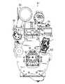
図1、図2において本発明のガバナ装置を具備する燃料噴射ポンプを装着するエンジンの構成について説明する。エンジン61は、クランクケース62、シリンダー部63およびシリンダヘッド部64により構成されており、該エンジン61のシリンダヘッド部64の側方には排気装置65が配設されている。エンジン61の側部には燃料噴射ポンプ1が配設されており、図示しない燃料タンクより供給される燃料を各シリンダ内に高圧で供給可能に構成されている。該エンジン61には燃料噴射ポンプ1より燃料が供給され、該燃料は空気とともにシリンダー部63内に導入される。シリンダー部63内には図示しない複数もしくは単数のシリンダおよびピストンが配設されており、前記導入された燃料と空気はシリンダにおいて図示しないピストンにより圧縮され、爆発した後に排気ガスとしてシリンダ部63より排出される。該シリンダ部63より排出される排気ガスはシリンダヘッド部64より排出される。
【0013】
該シリンダヘッド部64には、図示しないバルブ機構が配設されており、該シリンダ部64内において生成した排気ガスが、バルブ機構を介してシリンダヘッド部64に配設された排気マニホールド66内に排出される。各シリンダより排出された排気ガスは排気マニホールド66に集合し、該排気マニホールド66には前記排気装置65が接続されている。該構成において排気マニホールド66に集合させられた排気ガスが該排気装置65内に導入される構成になっている。該燃料噴射ポンプ1にはエンジン61よりの駆動力が伝達されており、該エンジン61の各シリンダに対する燃料の噴射タイミングは燃料噴射ポンプ1において調節される。該燃料噴射ポンプ1に伝達される動力はエンジン61のクランクケース62内に内包されるクランク軸に同期しており、燃料噴射ポンプ1において燃料噴射時期を調節することにより、シリンダー部63に内装されるピストンの摺動に対応した燃料の噴射をおこなうことできる。燃料噴射ポンプ1より噴射された燃料はシリンダ部63に内装される各シリンダ内に図示しない噴油弁を介して噴射される。
【0014】
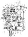
次に、本発明の実施形態にかかる燃料噴射ポンプのガバナ装置の全体構成について説明する。図3、図4において、燃料噴射ポンプ1の下部にはカム5を備えたカム軸4が横設され、図3における右側に配置される該カム軸4の駆動側4aは、カム軸受12を介して本体ハウジング28に回転自在に軸支されている。また、カム軸4の駆動側4a端部には、カム5の位置決めを行う位置決めキー13が装着されている。前記カム5の上方においては、プランジャバレル8に上下摺動自在に嵌挿されたプランジャ7が配設され、該プランジャ7の下端にはタペット11が付設されている。プランジャ7及びタペット11はスプリング22等の付勢手段により下方へ付勢され、該タペット11がカム5に当接している。該スプリング22は、上部受部材23と下部受部材24との間に介装されている。そして、カム5の回転によりプランジャ7が上下動するように構成している。
【0015】
また、前記プランジャ7の側方には、分配軸9が該プランジャ7と軸心を平行に配設されており、該分配軸9は分配軸スリーブ10に回転自在に嵌挿されるとともに、該分配軸9の下端部に連結した分配駆動軸19により回転駆動される。該分配駆動軸19及び分配軸9はカム軸4と直交する方向に配置されている。また、図4の如く、カム軸4の側方にフィードポンプ6を取り付けて、該カム軸4の回転により駆動し、フィルタを内蔵する管継手6aよりヘッドハウジング28a内の燃料ギャラリ43に燃料を供給するようにしている。
【0016】
このように構成した燃料噴射ポンプ1において、プランジャ7が上下動範囲の下端部に位置すると、前記フィードポンプ6により燃料ギャラリ43へ圧送される燃料が、吸込ポート14を通じてプランジャバレル8内へ圧送される。プランジャ7がカム5により押し上げられて上昇すると、プランジャバレル8内の燃料は、分配軸スリーブ10及び分配軸9を介してデリベリバルブ18へ圧送され、該デリベリバルブ18に連結された燃料噴射弁から噴射される。この場合、カム軸4と連動して回転する分配軸9により、燃料は複数のデリベリバルブ18へ分配されて圧送される。
【0017】
そして、プランジャ7は、該プランジャ7外周部の制御スリーブ17と、軸心を中心にして一体的に回動可能であり、後述するガバナ機構により制御スリーブ17を回動させることで、プランジャ7に形成されたプランジャリード16の位置を変化させて、燃料噴射弁から噴射する燃料量を調節することができる。前記プランジャ7、分配軸9、及びデリベリバルブ18等はヘッドハウジング28aに装着されて、ヘッド仕組部Bを構成しており、本体ハウジング28に内装されるカム軸4、カム5、及びタペット11等にて、ロア仕組部Aを構成している。
【0018】
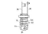
図3、図5に示すように、ガバナハウジング36内においては、カム軸4の回転にて作動するガバナ機構が組み込まれて、ガバナ装置であるガバナ機構部Cを構成している。即ち、該カム軸4の先端が、本体ハウジング28よりガバナハウジング36内に突入しており、ガバナウェイト支持部材32の中心に固設され、ガバナスリーブ30内に挿入されている。該ガバナウェイト支持部材32にはガバナウェイト31・31・・・が枢支されていて、カム軸4と一体の該ガバナウェイト支持部材32が回転すると、その回転に伴って発生する遠心力にて、ガバナウェイト31・31・・・が開き、該ガバナスリーブ30を、図中左側に押し出す。該ガバナスリーブ30は、第一ガバナレバー29aに装着されるシフター85に当接している。
【0019】
ガバナレバー29は、例えば、第一ガバナレバー29aと第二ガバナレバー29bとで構成され、該第一ガバナレバー29aと第二ガバナレバー29bとは、例えば引っ張りばねで構成されるセットスプリング89により、運転中は回動中心29cを中心に一体的に回動するように連結されている。該第一ガバナレバー29aとテンションレバー86とは、ばね等により一体的に回動可能に連結されている。また、テンションレバー86とコントロールレバー87との間にはガバナスプリング88が介装されており、該ガバナスプリング88の付勢力により、第一ガバナレバー29aのシフター85装着部分がガバナスリーブ30方向に付勢されている。
【0020】
カム軸4の回転が速いほど、前記ガバナウェイト31の開度が大きくなり、ガバナスリーブ30の押し出し量、即ち摺動量は大きくなる。該ガバナスリーブ30が摺動することにより、シフター85が押圧されて第一ガバナレバー29aが回動し、該シフター85が押圧されることによる第一ガバナレバー29aの回転トルクの大きさと、該回転トルクと反対方向に働くガバナスプリング88の付勢力による第一ガバナレバー29aの回転トルクの大きさとが釣り合う位置で、該第一ガバナレバー29aが停止する。そして、第一ガバナレバー29aと一体的に回動動作する第二ガバナレバー29bの動きにより、該第二ガバナレバー29bに接続されるリンク27を介して、コントロールラック21が摺動される。該コントロールラック21は制御スリーブ17に連結されていて、その摺動により制御スリーブ17を回動させ、これと一体にプランジャ7を回動させて、そのプランジャリード16が吸込ポート14に連通する位置を上下調節して、プランジャ7の有効ストローク即ち燃料圧送量を調節して、調速作用を行うようにしている。
【0021】
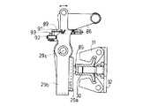
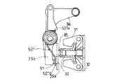
次に、第一ガバナレバー29aと第二ガバナレバー29bとの相対位置を調節する参考例の機構について図6、図7により説明する。前述の如く、第一ガバナレバー29aと第二ガバナレバー29bとはセットスプリング89により一体的に連結されており、該セットスプリング89の第一ガバナレバー29a側端部は、該第一ガバナレバー29aのブラケット部91に係止されている。該ブラケット部91には螺子部材92を回転可能に螺挿し、該螺子部材91の第二ガバナレバー29b側端部は、該第二ガバナレバー29bに当接している。また、螺子部材92には、該螺子部材92の回転を規制可能とする固定ナット93が螺嵌されている。
【0022】
そして、第一ガバナレバー29aのブラケット部91に螺挿した螺子部材92を、第二ガバナレバー29b側へ移動する方向に回転させると、該螺子部材92が第二ガバナレバー29bを押圧し、該第二ガバナレバー29bがセットスプリング89の付勢力に抗して、ブラケット部91から離れる方向に回動し、第一ガバナレバー29aと第二ガバナレバー29bとの相対位置が変化する。一方、螺子部材92を、反第二ガバナレバー29b側へ移動する方向に回転させると、セットスプリング89の付勢力により、第二ガバナレバー29bがブラケット部91へ近づく方向に回動し、第一ガバナレバー29aと第二ガバナレバー29bとの相対位置が変化する。即ち、螺子部材92を回転操作することにより、第一ガバナレバー29aと第二ガバナレバー29bとの相対位置を調節するように構成している。尚、螺子部材92を回転操作して、第一ガバナレバー29aと第二ガバナレバー29bとの相対位置を調節した後は、固定ナット93を締めることにより、該螺子部材92が回転することを規制して、第一ガバナレバー29aと第二ガバナレバー29bとの相対位置を固定することができる。
【0023】
このように、第一ガバナレバー29aと第二ガバナレバー29bとの相対位置を調節する螺子部材92を設けることにより、第一ガバナレバー29aの位置を固定してガバナ機構の使用域を一定に保持したまま、第二ガバナレバー29bの位置のみを変化させて燃料噴射量を調整することができる。これにより、構成部材のバラツキ等による固体差を吸収することができ、構成部材のバラツキ等にかかわらず、ガバナ機構の使用域を一定としてエンジン出力のばらつきを低減することが可能となる。
【0024】
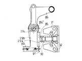
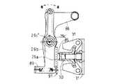
また、第一ガバナレバー29aと第二ガバナレバー29bとの相対位置を調節する機構は、図8、図9に示すように構成することもできる。第一ガバナレバー29aと第二ガバナレバー29bを一体的に連結するセットスプリング89は、本例においては第一・第二ガバナレバー29a・29b下端部に配置されている。第一ガバナレバー29aは、ガバナシャフト95に回動自在に枢支され、前記第二ガバナレバー29bは、ガバナシャフト95に枢支されるガバナブッシュ97に回動自在に枢支されたボス部98の外周に枢支されている。該ガバナブッシュ97において、第二ガバナレバー29bの回動中心であるボス部98内にガバナブッシュ97のブッシュ部分97aを配設し、該ブッシュ部分97aに穿設するガバナシャフト95嵌挿用の軸孔の軸心位置は、該ブッシュ部分97aの軸心位置とは偏心位置である回動中心29cに構成し、従って、ブッシュ部分97aの軸心、即ちボス部98の軸心29c’は、第一ガバナレバー29aの回動中心29cであるガバナシャフト95の軸心とは偏心している。
【0025】
このような第二ガバナレバー29bの中心支持構造により、図10、図11に示すように、ガバナブッシュ97が回動すると、第一ガバナレバー29aの回動中心29cに対して、第二ガバナレバー29bの回動中心29c’の位置が変化するため、該ガバナブッシュ97を回動操作することにより、ガバナスリーブ30及び第一ガバナレバー29aの位置を一定に保持したまま、第二ガバナレバー29bの回動中心29c’の位置を変化させて、燃料噴射量の増減調節を行うことができる(図10、図11においては、例えば、燃料噴射量が増加する方向にガバナブッシュ97を回動操作した状態を示している。)。尚、ガバナブッシュ97を回動操作は、ガバナハウジング36の外部から行うことができるように構成している。
【0026】
このように、第一ガバナレバーの回動中心と第二ガバナレバーの回動中心とを偏心させるガバナブッシュ97によって、該第一ガバナレバーと第二ガバナレバーとの相対位置を調節する機構を構成することにより、該ガバナブッシュ97を回動操作するだけの簡単な作業で、該第一ガバナレバーと第二ガバナレバーとの相対位置を、容易且つ精度良く調節することができ、エンジン出力のばらつきを低減することが可能となる。
【0027】
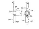
次に、第一ガバナレバー29aと第二ガバナレバー29bとを一体的に連結するセットスプリングを捩じりばねにより構成した例について説明する。図12、図13に示すように、前記ガバナブッシュ97に嵌装される第二ガバナレバー29bのボス部98の外周部には、捩じりばねにより構成されるセットスプリング501が装着されている。該セットスプリング501の一端部501aは、第二ガバナレバー29bの、例えば回動中心29c’よりも上方部分に係止し、他端部は501bは、第一ガバナレバー29aの回動中心29cよりも下部に配置されるブラケット部91に係止されている。そして、セットスプリング501は、第一ガバナレバー29aのブラケット部91と、第二ガバナレバー29bの下端部が圧接する方向に、両者を付勢しており、該 セットスプリング501により第一ガバナレバー29aと第二ガバナレバー29bとが一体的に連結されているのである。
【0028】
このように、第一ガバナレバー29aと第二ガバナレバー29bとを一体的に連結するセットスプリング501を、捩じりばねにより構成することにより、該セットスプリング501の取付荷重を大きくするとともに、ばね定数を小さく設定して構成した場合でも、小さなスペースでセットスプリング501を装着することができ、ガバナ装置の小型化を図ることが可能である。また、第一ガバナレバー29a及び第二ガバナレバー29bをガバナハウジング36にセットする場合には、第二ガバナレバー29bに装着したセットスプリング501の他端部501bを第一ガバナレバー29aのブラケット部91に係止するだけで、該セットスプリング501をセットすることができるので、ガバナ機構部Cの仕組性を向上することができる。
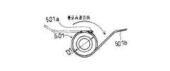
【0029】
また、捩じりばねにより構成したセットスプリング501を装着する第二ガバナレバー29bには、図14に示すように、セットスプリング501の他端部501b側を係止するプリセット座99を形成することもできる。即ち、セットスプリング501の一端部501aを第二ガバナレバー29bの、例えば回動中心29c’よりも上方部分に係止させるとともに、他端部501b側を、荷重をかけないセットスプリング501の自由時の状態501’から、巻き込んで荷重をかけた状態でプリセット座99に係止するのである。そして、セットスプリング501を第二ガバナレバー29bに装着した状態で、予め該第二ガバナレバー29bと第一ガバナレバー29aとを仕組み、仕組んだ状態の第一・第二ガバナレバー29a・29bをガバナハウジング36にセットし、その後、プリセット座99に係止しているセットスプリング501の他端部501bを、図14に示すセットスプリング501の取付時の状態501”の如く、第一ガバナレバー29aのブラケット部91に係止させるのである。
【0030】
このように、予め第二ガバナレバー29b単体で、装着されたセットスプリング501を、取付時の状態501”又はそれ以上の荷重がかかった状態で保持し、この状態で該第二ガバナレバー29bと第一ガバナレバー29aとを仕組んだ後に、ガバナハウジング36にセットすることができるため、ガバナ機構部Cの仕組性をさらに向上することができる。尚、プリセット座99は、セットスプリング501の荷重が、取付時の状態501”における荷重よりも小さくなるような位置に、該セットスプリング501の他端部501bを係止するように形成することも可能である。
【0031】
また、セットスプリング501を装着する第二ガバナレバー29bのボス部98の端部には、図17に示すように、半径方向外側に突出するツバ部98aを形成することができる。該ツバ部98aの外径dは、図17に示す巻き込み逆方向の最大荷重時におけるセットスプリング501の最大内径D1よりも小径で、且つ、図15に示すようにセットスプリング501を第一・第二ガバナレバー29a・29bに装着した取付時の状態における、該セットスプリング501の内径D2よりは大径に、該ツバ部98aの外径dは形成されている。尚、図16にはセットスプリング501の自由時内径D0を示している。
【0032】
このようにツバ部98aを形成することで、第二ガバナレバー29bのボス部98に装着されたセットスプリング501が、該ツバ部98aに係止して、該ボス部98から外側にはみ出すことを防止することができる。これにより、ツバ部98aをボス部98に形成しなかった場合のように、セットスプリング501がボス部98の外側にはみ出してガバナハウジング36と干渉し、ガバナ特性を悪化させることを防止することができる。また、ツバ部98aの外径dは、セットスプリング501の最大内径D1よりも小さく形成しているので、ボス部98のツバ部98a形成側からセットスプリング501を着脱することが可能であり、第二ガバナレバー29bとボス部98とを結合する作業と同時に、反ツバ部98a側からセットスプリング501を装着するといった煩わしい作業を行う必要がなくなるので、セットスプリング501の交換等の着脱作業を容易にすることができる。
【0033】
ここで、図13に示すセットスプリング501の他端部501bは、第一ガバナレバー29aのブラケット部91の、第二ガバナレバー29bが当接する部分よりも外側に当接しているが、該セットスプリング501の他端部501bが当接する部分と第二ガバナレバー29bが当接する部分が左右方向にずれているために、セットスプリング501の付勢力によって、第一ガバナレバー29aに捩じり方向の力が作用することとなる。この捩じり方向の力は、第一ガバナレバー29aの回動動作に対して抵抗となるため、ガバナ特性の悪化を招いてしまう。
【0034】
従って、この捩じり方向の力の発生を防ぐために、ブラケット部91に当接する第二ガバナレバー29bとセットスプリング501の他端部501bとの位置関係を次のように構成することができる。即ち、図18に示す如く、セットスプリング501の他端部501bを屈曲させて、ブラケット部91に当接する該他端部501bと第二ガバナレバー29bとの左右位置を一致させたり、図19に示す如く、第二ガバナレバー29bの下端部に左右方向に突出する突起部100を形成して、該突起部100をブラケット部91に当接させ、ブラケット部91に当接する該他端部501bと第二ガバナレバー29bとの左右位置を一致させたりするのである。
【0035】
このように、ブラケット部91に当接する該他端部501bと第二ガバナレバー29bとの左右位置を一致させることにより、第一ガバナレバー29aに捩じり方向の力が作用することを防止して、ガバナ特性に悪影響を及ぼすことを防ぐことができる。
【0036】
次に、ガバナレバー29に設けられ、ガバナスリーブ30に当接する前記シフタ85をローラ部材等により構成した例について説明する。図20、図21に示すように、上下方向においてガバナスリーブ30が位置する部分のガバナレバー29には、該ガバナスリーブ30の摺動方向と直交する方向に、シフターピン505が横設されて支持されている。該シフターピン505の外周部にはシフターローラ506が、シフターピン505の軸心を中心として回転自在に嵌装され、該シフターローラ506はガバナスリーブ30に当接している。本例においては、シフターローラ506は、ガバナスリーブ30の図21における左右方向の全範囲にわたって当接している。
【0037】
このように、シフタ85をガバナレバー29に支持されるシフターピン505と、該シフターピン505に回転自在に嵌装されるシフターローラ506とで構成することで、ガバナスリーブ30がシフタ85を介してガバナレバー29を押圧し、該ガバナレバー29が回動された際には、該ガバナレバー29の回動に伴ってシフターローラ506が回転することとなり、該シフターローラ506のガバナスリーブ30との接触面がガバナレバー29の回動に伴って移動するため、該シフターローラ506外周のガバナスリーブ30との接触面が局所的に磨耗することを防ぐことができるとともに、シフターローラ506とガバナスリーブ30との接触面の抵抗を低減することができ、エンジン特性が劣化することを防止できる。
【0038】
しかし、運転時には、ガバナスリーブ30はカム軸4と一体的に回転しながらシフターローラ506に当接しているが、図21における該シフターローラ506は、ガバナスリーブ30の左右方向の全範囲にわたって当接しているために、ガバナスリーブ30の回転によりシフターローラ506が回転することはなく、シフターローラ506はガバナレバー29の回動に伴ってのみ回転する。従って、ガバナレバー29が回動しなければ、シフターローラ506の同一面がガバナスリーブ30と当接して摩擦されることとなる。
【0039】
そこで、この摩擦を低減するために、ガバナスリーブ30の回転に伴ってシフターローラ506が回転するように構成した例について説明する。例えば、図22に示すように、シフターローラ506を、ガバナスリーブ30左右全範囲にわたって当接するようには設けず、該シフターローラ506がガバナスリーブ30の左右片側に偏って当接するように設けている。このように、シフターローラ506をガバナスリーブ30の左右片側に偏って当接させることにより、ガバナスリーブ30の回転に伴ってシフターローラ506が回転することとなる。また、図23に示すように、2分割したシフターローラ506が、それぞれガバナスリーブ30の略左半分又は略右半分の範囲に当接するように、該シフターローラ506を設けることもできる。このように、シフターローラ506を2分割して、それぞれをガバナスリーブ30の略左半分又は略右半分の範囲に当接させることにより、ガバナスリーブ30の回転に伴って、左右のシフターローラ506がそれぞれ逆方向に回転することとなる。
【0040】
以上の如く、ガバナスリーブ30の回転に伴って、シフターローラ506が回転するように構成することにより、シフターローラ506のガバナスリーブ30への当接面が摩擦されることを防止して、該シフターローラ506の磨耗を低減することができるとともに、ガバナレバー29が回動しなくてもシフターローラ506のガバナスリーブ30への当接面が積極的に変化されて、該シフターローラ506の偏磨耗を防止することができる。
【0041】
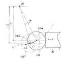
次に、ガバナスリーブ30に当接するシフタ85の配置位置について、図24及び図25より説明する。図24には、シフタ85をシフターピン505及びシフターローラ506にて構成した例を示しているが、シフターローラ506は、定格出力時における該シフターローラ506の円弧中心であるシフターピン505の軸心505aが、ガバナレバー29の回動中心29cよりも下方、且つ、ガバナスリーブ30側寄りに位置するように配置されている。
【0042】
図25には、定格出力時におけるシフターローラ506の円弧中心である軸心505aの配置位置、及び、定格出力時よりも燃料噴射量が少ないハイアイドル時におけるシフターローラ506’の円中心である軸心505a’の配置位置を示しているが、該軸心は、ガバナスリーブ30により水平方向の押圧力(この押圧方向をFとする。)が該シフターローラー506に加わるにつれ、ガバナレバー29の回動中心29cとの間に一定の寸法Wを保ちながら移動するため、ハイアイドル時における軸心505a’は、定格出力時における軸心505aよりも下方に位置している。即ち、定格出力時におけるシフターローラー506の軸心506aとガバナレバー29の回動中心29cとの間の鉛直方向距離(押圧方向Fに対して垂直方向)Y1よりも、ハイアイドル時におけるシフターローラー506’の軸心506a’と該回動中心29cとの間の鉛直方向距離(押圧方向Fに対して垂直方向)Y2が大きくなる。
【0043】
ここで、ガバナスリーブ30に押圧されてガバナレバー29が回動されると、それに伴ってシフターローラ506の円弧中心である軸心505aは、回動中心29cを中心とする円弧である回動軌跡U上を回動する。また、定格出力時には、ガバナスリーブ30に押圧されたシフターローラ506は、回動軌跡Uの軸心505aにおける接線方向C1に回動し、ハイアイドル時には、ガバナスリーブ30に押圧されたシフターローラ506’は、回動軌跡Uの軸心505a’における接線方向C2に回動する。そして、ガバナスリーブ30の押圧方向Fとハイアイドル時のシフターローラ506’の回動方向である接線方向C2とがなす角度は、該押圧方向Fと定格出力時のシフターローラ506の回動方向である接線方向C1とがなす角度よりも小さいため、ガバナスリーブ30より伝達されるシフターローラ506・506’の回動力は、ハイアイドル時におけるシフターローラ506’の回動力の方が大きくなる。即ち、ガバナスリーブ30がシフターローラ506を押圧して回動させる場合、ガバナスリーブ30からのウェイトフォースが仮に同一であっても、回動量が大きくなるほどシフターローラ506を回動する回動力は大きくなり、且つ、鉛直方向距離Y1よりも鉛直方向距離Y2の方が長いため、ガバナレバー29を回動させるトルクも定格出力時よりもハイアイドル時において大きくなるのである。
【0044】
以上の如く、ガバナスリーブ30による押圧方向Fの押圧力にて、該シフターローラー506が、その軸心とガバナレバー29の回動中心29cとの間に一定の寸法Wを保ちながら回動する構造において、定格出力時におけるシフターローラー506の軸心506aとガバナレバー29の回動中心29cとの間の鉛直方向距離(押圧方向Fに対して垂直方向)Y1よりも、ハイアイドル時におけるシフターローラー506’の軸心506a’と該回動中心29cとの間の鉛直方向距離(押圧方向Fに対して垂直方向)Y2が大きくなるようにシフターローラー506即ちシフター85の位置を設定したので、ガバナスリーブ30により回動されるシフターローラ506の回動量が大きくなるほど、シフターローラー506(シフター85)の移動方向とガバナスリーブ30の作動方向とのなす角度が小さくなり、即ち、該シフターローラー506の移動方向が該ガバナスリーブ30の作動方向に近くなり、ガバナスリーブ30からのウェイトフォースを有効にシフターローラ506の回動力、即ちガバナレバー29の回動力に変換することができ、ひいてはガバナレバー29の回転トルクに有効に変換することができて、同じ重さのガバナウェイト31を用いた場合、制御力を大きくすることができる。また、これにより、ガバナ機構部Cをコンパクトに構成することもできる。
【0045】
即ち、ガバナスリーブに当接するシフターを、該ガバナレバーに支持されたシフターピンと該シフターピンに回転自在に嵌装されたシフターローラとで構成したので、ガバナスリーブがシフタを介してガバナレバーを押圧して該ガバナレバーが回動された際には、該ガバナレバーの回動に伴ってシフターローラが回転することとなり、該シフターローラのガバナスリーブとの接触面がガバナレバーの回動に伴って移動するため、該シフターローラ外周のガバナスリーブとの接触面が局所的に磨耗することを防ぐことができるとともに、シフターローラとガバナスリーブとの接触面の抵抗を低減することができ、エンジン特性が劣化することを防止できる。
【0046】
また、ガバナレバーの回動中心からガバナスリーブに当接するシフターのガバナスリーブへの当接部までの鉛直方向距離が、定格出力時よりもハイアイドル時において大きくなるように、ガバナスリーブに対するシフターの相対位置を設定したので、ガバナスリーブにより回動されるシフターローラの回動量が大きくなるほど、ガバナスリーブからのウェイトフォースを有効にシフターローラの回動トルク、即ちガバナレバーの回動トルクに変換することができ、同じ重さのガバナウェイトを用いた場合、制御力を大きくすることができる。また、これにより、ガバナ機構部をコンパクトに構成することもできる。
【0047】
【発明の効果】
本発明は以上の如く構成したので、次のような効果を奏するのである。
請求項1記載の如く、ガバナレバー(29)が、ガバナウェイト(31)からのウェイトフォースを受ける第一ガバナレバー(29a)と、燃料噴射ポンプ(1)の調量機構に連結される第二ガバナレバー(29b)とに分割して構成された燃料噴射ポンプ(1)のガバナ装置において、該第一ガバナレバー(29a)と第二ガバナレバー(29b)との相対位置を調節可能に構成したので、第一ガバナレバーの位置を固定してガバナ機構の使用域を一定に保持したまま、第二ガバナレバーの位置のみを変化させて燃料噴射量を調整することができる。
これにより、構成部材のバラツキ等による固体差を吸収することができ、構成部材のバラツキ等にかかわらず、ガバナ機構の使用域を一定としてエンジン出力のばらつきを低減することが可能となる。
【0046】
また、相対位置調節機構は、前記第一ガバナレバー(29a)をガバナシャフト(95)に枢支し、前記第二ガバナレバー(29b)を該ガバナシャフト(95)にガバナブッシュ(97)を介して枢支されるボス部(98)に枢支し、該ガバナブッシュ(97)のブッシュ部分(97a)がガバナシャフト(95)に嵌挿される軸孔の中心は、ブッシュ部分(97a)の中心とは偏心位置に構成し、前記ボス部(98)の軸心(29c’)は、第一ガバナレバー29aの回動中心(29c)であるガバナシャフト(95)の軸心とは偏心し、該ガバナブッシュ(97)を回動操作することにより、第一ガバナレバー(29a)の位置を一定に保持したまま、該第二ガバナレバー(29b)の回動中心(29c’)の位置を変化させて、燃料噴射量の増減調節を可能としたので、該偏心軸を回動操作するだけの簡単な作業で、該第一ガバナレバーと第二ガバナレバーとの相対位置を、容易且つ精度良く調節することができ、エンジン出力のばらつきを低減することが可能となる。
【0047】
請求項2に記載のごとく、前記ガバナ装置において、第一ガバナレバー(29a)と第二ガバナレバー(29b)とを一体的に連結するセットスプリング(501)を捩じりばねにより構成し、前記第二ガバナレバー(29b)のボス部(98)の外周部に装着したので、該セットスプリングを、取付荷重を大きくするとともに、ばね定数を小さく設定して構成した場合でも、小さなスペースで該セットスプリングを装着することができ、ガバナ装置の小型化を図ることが可能である。
また、セットスプリングを装着性が良好になるので、ガバナ機構部の仕組性を向上することができる。
【0048】
請求項3に記載のごとく、第二ガバナレバーにセットスプリングを装着し、該第二ガバナレバーに、自由時よりも荷重をかけた状態のセットスプリングを係止するためのプリセット座を形成したので、予め第二ガバナレバー単体で、装着されたセットスプリングを、自由時よりも荷重がかかった状態で保持し、この状態で該第二ガバナレバーと第一ガバナレバーとを仕組みんだ後に、ガバナハウジングにセットすることができるため、ガバナ機構部の仕組性をさらに向上することができる。
【0049】
請求項4に記載のごとく、セットスプリングが装着される第二ガバナレバーのボス部に、該セットスプリングが取り得る最大内径よりも小径、且つ、該セットスプリングの装着時の内径よりも大径であるツバ部を形成したので、第二ガバナレバーのボス部に装着されたセットスプリングが、該ボス部から外側にはみ出すことを防止することができる。
これにより、ツバ部をボス部に形成しなかった場合のように、セットスプリングがボス部の外側にはみ出してガバナハウジングと干渉し、ガバナ特性を悪化させることを防止することができる。
また、ボス部のツバ部形成側からセットスプリングを着脱することが可能であり、第二ガバナレバーとボス部とを結合する際に、反ツバ部側からセットスプリングを装着するといった煩わしい作業を行う必要がなくなるので、セットスプリングの交換等の着脱作業を容易にすることができる。
【図面の簡単な説明】
【図1】 燃料噴射ポンプを装着したエンジンの側面図である。
【図2】 同じく後面図である。
【図3】 燃料噴射ポンプの側面図である。
【図4】 同じく正面図である。
【図5】 ガバナ機構部を示す正面図である。
【図6】 第一ガバナレバーと第二ガバナレバーとの相対位置を調節する機構を示す参考例の側面図である。
【図7】 同じく正面図である。
【図8】 第一ガバナレバーと第二ガバナレバーとの相対位置を調節する機構の別実施例を示す側面図である。
【図9】 同じく正面図である。
【図10】 図8、図9の相対位置調節機構により第一ガバナレバーと第二ガバナレバーとの相対位置を調節した状態を示す側面図である。
【図11】 図10における第一ガバナレバーの回動中心と第二ガバナレバーの回動中心との位置関係を示す図である。
【図12】 セットスプリングを捩じりばねで構成した場合のガバナレバー部を示す側面図である。
【図13】 同じく正面図である。
【図14】 第二ガバナレバーにプリセット座を形成し捩じりばねにより構成したセットスプリングを荷重をかけた状態にて第二ガバナレバー単体で係止した状態を示す図である。
【図15】 ボス部にツバ部を形成した第二ガバナレバーに捩じりばねにより構成したセットスプリングを装着した状態を示す図である。
【図16】 捩じりばねにより構成したセットスプリングの自由時内径を示す図である。
【図17】 捩じりばねにより構成したセットスプリングの最大内径を示す図である。
【図18】 第一ガバナレバーのブラケット部に当接する捩じりばねにより構成したセットスプリングと第二ガバナレバーとの左右位置を一致させたガバナレバーを示す図である。
【図19】 図18の別実施例を示す図である。
【図20】 シフターをシフターピンとシフターローラとにより構成した例を示す側面図である。
【図21】 同じく正面図である。
【図22】 ガバナスリーブの回転に伴ってシフターローラが回転する構成とした例を示す正面図である。
【図23】 図22の別参考例を示す図である。
【図24】 はシフターローラの円弧中心の配置位置を示す側面図である。
【図25】 定格出力時及びハイアイドル時におけるシフターローラの円弧中心の配置位置を示す図である。
【符号の説明】
C ガバナ機構部
1 燃料噴射ポンプ
4 カム軸
29 ガバナレバー
29a 第一ガバナレバー
29b 第二ガバナレバー
29c 回動中心
30 ガバナスリーブ
36 ガバナハウジング
85 シフター
89 セットスプリング
91 ブラケット部
92 螺子部材
97 ガバナブッシュ(偏心軸)
98 (第二ガバナレバーの)ボス部
501 (捩じりばねにより構成した)セットスプリング
505 シフターピン
506 シフターローラ[0001]
BACKGROUND OF THE INVENTION
The present invention relates to a configuration of a governor device of a fuel injection pump that receives a weight force from a governor weight and operates a metering mechanism for metering a fuel injection amount of the fuel injection pump.
[0002]
[Prior art]
Conventionally, in a governor device of a fuel injection pump, a governor lever that receives a weight force from a governor weight and is connected to a metering mechanism of the fuel injection pump and operates the metering mechanism according to the magnitude of the weight force. Is divided into a first governor lever that receives the weight force and a second governor lever that is connected to the metering mechanism, thereby forming a so-called three-lever type governor mechanism. The first governor lever and the second governor lever are integrally connected by a set spring, and the set spring is constituted by a tension spring. The weight force is transmitted to the first governor lever via a governor sleeve that presses the first governor lever by the weight force, and a shifter that is attached to the first governor lever and contacts the governor sleeve. The contact portion of the shifter with the governor sleeve was formed in a substantially arc shape, and the position of the contact portion of the shifter was fixed.
[0003]
[Problems to be solved by the invention]
However, since the relative position of the first governor lever and the second governor lever is configured to be unadjustable, the dimension of the member related to increase / decrease of the injection amount when there is no injection amount adjustment mechanism on the metering mechanism side of the fuel injection pump. The range of use of the governor has changed due to variations and the like, causing variations in engine output. Further, the set spring increases the mounting load so that the first and second governor levers are not separated during operation, and the first and second governor levers can be pulled apart from each other with as little force as possible when stopped. Although it is necessary to set a small constant, the set spring is constituted by a tension spring. Therefore, if the mounting load and the spring constant are set so as to satisfy these conditions, the set spring has a large size. As a result, the housing of the governor device was enlarged. Furthermore, the connection between the first governor lever and the second governor lever by the set spring must be performed in the housing,It was difficult to perform the connecting work.
[0004]
[Means for Solving the Problems]
The problems to be solved by the present invention are as described above. Next, means for solving the problems will be described.
[0005]
In
[0006]
In claim 2, in the governor device, the set spring (501) integrally connecting the first governor lever (29a) and the second governor lever (29b) is constituted by a torsion spring,Mounted on the outer periphery of the boss (98) of the second governor lever (29b)Is.
[0007]
According to
[0008]
In claim 4, in the governor device, the boss portion (98) of the second governor lever (29b) to which the set spring (501) is attached has a smaller diameter than the maximum inner diameter that the set spring (501) can take, and The flange portion (98a) having a larger diameter than the inner diameter when the set spring (501) is mounted is formed.
[0009]
DETAILED DESCRIPTION OF THE INVENTION
Next, an embodiment of the present invention will be described. 1 is a side view of an engine equipped with a fuel injection pump, FIG. 2 is also a rear view, FIG. 3 is a side view of the fuel injection pump, FIG. 4 is a front view, and FIG. 5 is a front view showing a governor mechanism. 6 shows a mechanism for adjusting the relative position of the first governor lever and the second governor lever.reference7 is a front view, FIG. 8 is a side view showing another embodiment of a mechanism for adjusting the relative position of the first governor lever and the second governor lever, and FIG. 9 is a front view.
[0010]
10 is a side view showing a state in which the relative position between the first governor lever and the second governor lever is adjusted by the relative position adjusting mechanism shown in FIGS. 8 and 9, and FIG. 11 is a diagram illustrating the rotation center and second position of the first governor lever in FIG. FIG. 12 is a side view showing the governor lever portion when the set spring is constituted by a torsion spring, FIG. 13 is a front view of the same, and FIG. 14 is preset to the second governor lever. It is a figure which shows the state which locked the set spring which formed the seat and comprised with the torsion spring with the 2nd governor lever single-piece | unit in the state which applied the load.
[0011]
FIG. 15 is a view showing a state in which a set spring constituted by a torsion spring is mounted on a second governor lever having a flange portion formed on a boss portion, and FIG. 16 shows an inner diameter of the set spring constituted by a torsion spring when it is free. FIG. 17 is a diagram showing the maximum inner diameter of a set spring constituted by a torsion spring, and FIG. 18 is a left-right position of the set spring constituted by a torsion spring abutting on the bracket portion of the first governor lever and the second governor lever. FIG. 19 is a view showing another embodiment of FIG. 18, FIG. 20 is a side view showing an example in which a shifter is constituted by a shifter pin and a shifter roller, FIG. 21 is a front view, and FIG. FIG. 23 is a front view showing an example in which the shifter roller rotates with the rotation of the governor sleeve, and FIG.referenceFIG. 24 is a side view showing the arrangement position of the arc center of the shifter roller, and FIG. 25 is a diagram showing the arrangement position of the arc center of the shifter roller at the rated output and during high idle.
[0012]
The configuration of an engine equipped with a fuel injection pump having the governor device of the present invention will be described with reference to FIGS. The
[0013]
The
[0014]
Next, the overall configuration of the governor device of the fuel injection pump according to the embodiment of the present invention will be described. 3 and 4, a cam shaft 4 having a cam 5 is provided in the lower part of the
[0015]
A
[0016]
In the
[0017]
The
[0018]
As shown in FIGS. 3 and 5, a governor mechanism that is operated by the rotation of the cam shaft 4 is incorporated in the
[0019]
The
[0020]
The faster the camshaft 4 rotates, the larger the opening of the
[0021]
Next, the relative position between the
[0022]
Then, when the
[0023]
In this way, by providing the
[0024]
Further, the mechanism for adjusting the relative position between the
[0025]
With the center support structure of the
[0026]
Thus, by configuring a mechanism for adjusting the relative position between the first governor lever and the second governor lever by the
[0027]
Next, an example in which a set spring that integrally connects the
[0028]
In this way, by configuring the
[0029]
Further, as shown in FIG. 14, a
[0030]
In this way, the
[0031]
Further, as shown in FIG. 17, a
[0032]
By forming the
[0033]
Here, the
[0034]
Therefore, in order to prevent the generation of the force in the twisting direction, the positional relationship between the
[0035]
Thus, by making the left and right positions of the
[0036]
Next, an example will be described in which the
[0037]
As described above, the
[0038]
However, during operation, the
[0039]
Therefore, an example in which the
[0040]
As described above, the
[0041]
Next, the arrangement position of the
[0042]
FIG. 25 shows an arrangement position of the
[0043]
Here, when the
[0044]
As described above, in the structure in which the
[0045]
That isThe shifter that abuts the governor sleeve is composed of a shifter pin supported by the governor lever and a shifter roller that is rotatably fitted to the shifter pin. When the governor lever is rotated, the shifter roller rotates with the rotation of the governor lever, and the contact surface of the shifter roller with the governor sleeve moves with the rotation of the governor lever. The contact surface with the outer governor sleeve can be prevented from being locally worn, and the resistance of the contact surface between the shifter roller and the governor sleeve can be reduced, and the engine characteristics can be prevented from deteriorating.
[0046]
AlsoThe relative position of the shifter with respect to the governor sleeve is set so that the vertical distance from the center of rotation of the governor lever to the contact portion of the shifter contacting the governor sleeve with the governor sleeve is greater at the time of high idle than at the rated output. As the amount of rotation of the shifter roller rotated by the governor sleeve increases, the weight force from the governor sleeve can be effectively converted into the rotation torque of the shifter roller, that is, the rotation torque of the governor lever. When the weight governor weight is used, the control force can be increased. Thereby, the governor mechanism part can also be constituted compactly.
[0047]
【The invention's effect】
Since the present invention is configured as described above, the following effects can be obtained.
The governor lever (29) includes a first governor lever (29a) for receiving a weight force from the governor weight (31) and a second governor lever (29) connected to a metering mechanism of the fuel injection pump (1). 29b) in the governor device of the fuel injection pump (1) configured so that the relative position between the first governor lever (29a) and the second governor lever (29b) can be adjusted. The fuel injection amount can be adjusted by changing only the position of the second governor lever while fixing the position of the governor mechanism and keeping the operating range of the governor mechanism constant.
Thereby, it is possible to absorb the solid difference due to the variation of the constituent members and the like, and it is possible to reduce the variation in the engine output while keeping the use range of the governor mechanism constant regardless of the variation of the constituent members.
[0046]
Also,In the relative position adjusting mechanism, the first governor lever (29a) is pivotally supported on the governor shaft (95), and the second governor lever (29b) is pivotally supported on the governor shaft (95) via the governor bush (97). The center of the shaft hole in which the bush portion (97a) of the governor bush (97) is inserted into the governor shaft (95) is eccentric from the center of the bush portion (97a). The axis (29c ′) of the boss portion (98) is eccentric from the axis of the governor shaft (95), which is the rotation center (29c) of the
[0047]
As described in claim 2In the governor device, the set spring (501) integrally connecting the first governor lever (29a) and the second governor lever (29b) is constituted by a torsion spring,Mounted on the outer periphery of the boss (98) of the second governor lever (29b)Therefore, even when the set spring is configured with a large mounting load and a small spring constant, the set spring can be mounted in a small space, and the governor device can be downsized. is there.
In addition, since the set spring can be easily mounted, the structure of the governor mechanism can be improved.
[0048]
As described in claim 3The second governor lever is fitted with a set spring, and the second governor lever is formed with a preset seat to lock the set spring in a state where a load is applied more than when free. Since the set spring is held in a state where a load is applied more than when it is free and the second governor lever and the first governor lever are structured in this state, the set spring can be set in the governor housing. Can be further improved.
[0049]
As described in claim 4The flange portion of the second governor lever to which the set spring is mounted is formed with a flange portion having a diameter smaller than the maximum inner diameter that the set spring can take and larger than the inner diameter when the set spring is mounted. It is possible to prevent the set spring mounted on the boss portion of the second governor lever from protruding outward from the boss portion.
As a result, as in the case where the brim portion is not formed on the boss portion, it is possible to prevent the set spring from protruding outside the boss portion and interfere with the governor housing to deteriorate the governor characteristics.
Moreover, it is possible to attach and detach the set spring from the brim part forming side of the boss part, and when connecting the second governor lever and the boss part, it is necessary to perform troublesome work such as mounting the set spring from the opposite brim part side. Therefore, attachment / detachment work such as replacement of the set spring can be facilitated.
[Brief description of the drawings]
FIG. 1 is a side view of an engine equipped with a fuel injection pump.
FIG. 2 is also a rear view.
FIG. 3 is a side view of the fuel injection pump.
FIG. 4 is a front view of the same.
FIG. 5 is a front view showing a governor mechanism.
FIG. 6 shows a mechanism for adjusting the relative position between the first governor lever and the second governor lever.Reference exampleIt is a side view.
FIG. 7 is a front view of the same.
FIG. 8 is a side view showing another embodiment of the mechanism for adjusting the relative position between the first governor lever and the second governor lever.
FIG. 9 is a front view of the same.
10 is a side view showing a state in which the relative positions of the first governor lever and the second governor lever are adjusted by the relative position adjusting mechanism shown in FIGS. 8 and 9. FIG.
11 is a diagram showing a positional relationship between the rotation center of the first governor lever and the rotation center of the second governor lever in FIG. 10;
FIG. 12 is a side view showing a governor lever portion when the set spring is constituted by a torsion spring.
FIG. 13 is a front view of the same.
FIG. 14 is a view showing a state in which a preset spring is formed on a second governor lever and a set spring constituted by a torsion spring is locked by a second governor lever alone in a state where a load is applied.
FIG. 15 is a view showing a state in which a set spring constituted by a torsion spring is attached to a second governor lever in which a flange portion is formed on a boss portion.
FIG. 16 is a diagram showing a free inner diameter of a set spring constituted by a torsion spring.
FIG. 17 is a diagram showing a maximum inner diameter of a set spring constituted by a torsion spring.
FIG. 18 is a view showing a governor lever in which left and right positions of a set spring constituted by a torsion spring abutting on a bracket portion of the first governor lever and a second governor lever are matched.
FIG. 19 is a diagram showing another embodiment of FIG.
FIG. 20 is a side view showing an example in which a shifter is constituted by a shifter pin and a shifter roller.
FIG. 21 is a front view of the same.
FIG. 22 is a front view showing an example in which a shifter roller rotates with the rotation of the governor sleeve.
FIG. 23 is different from FIG.referenceIt is a figure which shows an example.
FIG. 24 is a side view showing the arrangement position of the arc center of the shifter roller.
FIG. 25 is a diagram showing the arrangement position of the arc center of the shifter roller at the rated output and at the high idle time.
[Explanation of symbols]
C Governor mechanism
1 Fuel injection pump
4 Cam shaft
29 Governor lever
29a First governor lever
29b Second governor lever
29c Center of rotation
30 Governor sleeve
36 Governor housing
85 Shifter
89 Set spring
91 Bracket part
92 Screw member
97 Governor bush (Eccentric shaft)
98 Boss part (of the second governor lever)
501 Set spring (consisting of a torsion spring)
505 Shifter pin
506 Shifter roller
Claims (4)
Translated fromJapanesePriority Applications (1)
| Application Number | Priority Date | Filing Date | Title |
|---|---|---|---|
| JP03229099AJP4138132B2 (en) | 1999-02-10 | 1999-02-10 | Governor device for fuel injection pump |
Applications Claiming Priority (1)
| Application Number | Priority Date | Filing Date | Title |
|---|---|---|---|
| JP03229099AJP4138132B2 (en) | 1999-02-10 | 1999-02-10 | Governor device for fuel injection pump |
Publications (2)
| Publication Number | Publication Date |
|---|---|
| JP2000230433A JP2000230433A (en) | 2000-08-22 |
| JP4138132B2true JP4138132B2 (en) | 2008-08-20 |
Family
ID=12354841
Family Applications (1)
| Application Number | Title | Priority Date | Filing Date |
|---|---|---|---|
| JP03229099AExpired - Fee RelatedJP4138132B2 (en) | 1999-02-10 | 1999-02-10 | Governor device for fuel injection pump |
Country Status (1)
| Country | Link |
|---|---|
| JP (1) | JP4138132B2 (en) |
Cited By (1)
| Publication number | Priority date | Publication date | Assignee | Title |
|---|---|---|---|---|
| US7796002B2 (en) | 2004-09-30 | 2010-09-14 | Hitachi Metals, Ltd. | Magnetic field generator for MRI |
- 1999
- 1999-02-10JPJP03229099Apatent/JP4138132B2/ennot_activeExpired - Fee Related
Cited By (1)
| Publication number | Priority date | Publication date | Assignee | Title |
|---|---|---|---|---|
| US7796002B2 (en) | 2004-09-30 | 2010-09-14 | Hitachi Metals, Ltd. | Magnetic field generator for MRI |
Also Published As
| Publication number | Publication date |
|---|---|
| JP2000230433A (en) | 2000-08-22 |
Similar Documents
| Publication | Publication Date | Title |
|---|---|---|
| JP4224667B2 (en) | Fuel injection pump | |
| US20030075125A1 (en) | An oil pan for engines or transmissions | |
| WO2001057388A1 (en) | Fuel injection pump | |
| US7305946B2 (en) | Variable valve operating apparatus for internal combustion engine | |
| JP5145133B2 (en) | General-purpose engine exhaust gas recirculation structure | |
| JP4138132B2 (en) | Governor device for fuel injection pump | |
| US5803714A (en) | Swash plate type axial piston pump and method of assembling the same | |
| CN107575274B (en) | Variable valve mechanism, engine, and motorcycle | |
| JP4205595B2 (en) | Variable valve mechanism | |
| JP2003222063A (en) | Fuel high pressure pump equipped with integrated shutoff vane type pre-feed pump | |
| JP4178589B2 (en) | Auxiliary drive system for direct injection diesel engine | |
| US20050031478A1 (en) | Pump, especially for a fuel injection device for an internal combustion engine | |
| JP4220911B2 (en) | Variable valve mechanism | |
| JPS5865939A (en) | Regulator for number of revolution of fuel injection pump | |
| JPH0730717B2 (en) | Governor for fuel injection pump | |
| JP2592992Y2 (en) | Fuel control mechanism with boost compensator for fuel injection pump | |
| JPH08210447A (en) | Auto tensioner | |
| US6694939B2 (en) | Decompression unit for internal combustion engine | |
| JPS6017935B2 (en) | diesel engine fuel injection pump | |
| JP2019035404A (en) | Variable vale lift device of engine | |
| JP2013011207A (en) | Multiple linkage type piston to crank mechanism of internal combustion engine | |
| US5857444A (en) | Inner cam system distributor type fuel injector | |
| WO2015045858A1 (en) | Fuel injection pump | |
| US6488014B2 (en) | Fuel injection pump | |
| JP4138532B2 (en) | Distributed fuel injection pump |
Legal Events
| Date | Code | Title | Description |
|---|---|---|---|
| A621 | Written request for application examination | Free format text:JAPANESE INTERMEDIATE CODE: A621 Effective date:20050222 | |
| A131 | Notification of reasons for refusal | Free format text:JAPANESE INTERMEDIATE CODE: A131 Effective date:20080205 | |
| A521 | Written amendment | Free format text:JAPANESE INTERMEDIATE CODE: A523 Effective date:20080325 | |
| TRDD | Decision of grant or rejection written | ||
| A01 | Written decision to grant a patent or to grant a registration (utility model) | Free format text:JAPANESE INTERMEDIATE CODE: A01 Effective date:20080527 | |
| A01 | Written decision to grant a patent or to grant a registration (utility model) | Free format text:JAPANESE INTERMEDIATE CODE: A01 | |
| A61 | First payment of annual fees (during grant procedure) | Free format text:JAPANESE INTERMEDIATE CODE: A61 Effective date:20080605 | |
| R150 | Certificate of patent or registration of utility model | Free format text:JAPANESE INTERMEDIATE CODE: R150 | |
| FPAY | Renewal fee payment (event date is renewal date of database) | Free format text:PAYMENT UNTIL: 20110613 Year of fee payment:3 | |
| FPAY | Renewal fee payment (event date is renewal date of database) | Free format text:PAYMENT UNTIL: 20110613 Year of fee payment:3 | |
| FPAY | Renewal fee payment (event date is renewal date of database) | Free format text:PAYMENT UNTIL: 20120613 Year of fee payment:4 | |
| LAPS | Cancellation because of no payment of annual fees |