JP4137593B2 - Core for precision investment casting - Google Patents
Core for precision investment castingDownload PDFInfo
- Publication number
- JP4137593B2 JP4137593B2JP2002309155AJP2002309155AJP4137593B2JP 4137593 B2JP4137593 B2JP 4137593B2JP 2002309155 AJP2002309155 AJP 2002309155AJP 2002309155 AJP2002309155 AJP 2002309155AJP 4137593 B2JP4137593 B2JP 4137593B2
- Authority
- JP
- Japan
- Prior art keywords
- core
- refractory metal
- ceramic
- composite core
- metal element
- Prior art date
- Legal status (The legal status is an assumption and is not a legal conclusion. Google has not performed a legal analysis and makes no representation as to the accuracy of the status listed.)
- Expired - Fee Related
Links
- 238000005495investment castingMethods0.000titleclaimsabstractdescription15
- 239000000919ceramicSubstances0.000claimsabstractdescription65
- 239000003870refractory metalSubstances0.000claimsabstractdescription47
- 229910052751metalInorganic materials0.000claimsabstractdescription25
- 239000002131composite materialSubstances0.000claimsabstractdescription21
- 229910000601superalloyInorganic materials0.000claimsabstractdescription15
- 238000004519manufacturing processMethods0.000claimsabstractdescription6
- 239000002184metalSubstances0.000claimsdescription22
- 238000000034methodMethods0.000claimsdescription9
- 230000003647oxidationEffects0.000claimsdescription6
- 238000007254oxidation reactionMethods0.000claimsdescription6
- 239000000126substanceSubstances0.000claimsdescription2
- 239000011247coating layerSubstances0.000claims1
- 239000011224oxide ceramicSubstances0.000claims1
- 229910052574oxide ceramicInorganic materials0.000claims1
- 238000005266castingMethods0.000description18
- 238000001816coolingMethods0.000description17
- 239000000306componentSubstances0.000description12
- VYPSYNLAJGMNEJ-UHFFFAOYSA-NSilicium dioxideChemical compoundO=[Si]=OVYPSYNLAJGMNEJ-UHFFFAOYSA-N0.000description11
- 239000000463materialSubstances0.000description7
- 229910045601alloyInorganic materials0.000description6
- 239000000956alloySubstances0.000description6
- PNEYBMLMFCGWSK-UHFFFAOYSA-Naluminium oxideInorganic materials[O-2].[O-2].[O-2].[Al+3].[Al+3]PNEYBMLMFCGWSK-UHFFFAOYSA-N0.000description5
- 239000000377silicon dioxideSubstances0.000description5
- MCMNRKCIXSYSNV-UHFFFAOYSA-NZirconium dioxideChemical compoundO=[Zr]=OMCMNRKCIXSYSNV-UHFFFAOYSA-N0.000description4
- 150000002739metalsChemical class0.000description4
- 239000000243solutionSubstances0.000description4
- 229910001182Mo alloyInorganic materials0.000description3
- 238000009792diffusion processMethods0.000description3
- 229910000765intermetallicInorganic materials0.000description3
- 229910052750molybdenumInorganic materials0.000description3
- 229910052758niobiumInorganic materials0.000description3
- 239000010955niobiumSubstances0.000description3
- 239000002245particleSubstances0.000description3
- 239000002002slurrySubstances0.000description3
- 229910052715tantalumInorganic materials0.000description3
- 229910052721tungstenInorganic materials0.000description3
- PXHVJJICTQNCMI-UHFFFAOYSA-NNickelChemical compound[Ni]PXHVJJICTQNCMI-UHFFFAOYSA-N0.000description2
- 239000011230binding agentSubstances0.000description2
- 229910010293ceramic materialInorganic materials0.000description2
- 239000011248coating agentSubstances0.000description2
- 238000000576coating methodMethods0.000description2
- 238000004891communicationMethods0.000description2
- 230000007797corrosionEffects0.000description2
- 238000005260corrosionMethods0.000description2
- KZHJGOXRZJKJNY-UHFFFAOYSA-Ndioxosilane;oxo(oxoalumanyloxy)alumaneChemical compoundO=[Si]=O.O=[Si]=O.O=[Al]O[Al]=O.O=[Al]O[Al]=O.O=[Al]O[Al]=OKZHJGOXRZJKJNY-UHFFFAOYSA-N0.000description2
- 229910052863mulliteInorganic materials0.000description2
- 230000001681protective effectEffects0.000description2
- 238000003466weldingMethods0.000description2
- 241000588731HafniaSpecies0.000description1
- 229910020968MoSi2Inorganic materials0.000description1
- ZOKXTWBITQBERF-UHFFFAOYSA-NMolybdenumChemical compound[Mo]ZOKXTWBITQBERF-UHFFFAOYSA-N0.000description1
- BPQQTUXANYXVAA-UHFFFAOYSA-NOrthosilicateChemical compound[O-][Si]([O-])([O-])[O-]BPQQTUXANYXVAA-UHFFFAOYSA-N0.000description1
- WGLPBDUCMAPZCE-UHFFFAOYSA-NTrioxochromiumChemical compoundO=[Cr](=O)=OWGLPBDUCMAPZCE-UHFFFAOYSA-N0.000description1
- XSQUKJJJFZCRTK-UHFFFAOYSA-NUreaChemical compoundNC(N)=OXSQUKJJJFZCRTK-UHFFFAOYSA-N0.000description1
- 238000010306acid treatmentMethods0.000description1
- 230000001464adherent effectEffects0.000description1
- 229910052782aluminiumInorganic materials0.000description1
- 238000005452bendingMethods0.000description1
- 238000005219brazingMethods0.000description1
- 239000004202carbamideSubstances0.000description1
- 238000005524ceramic coatingMethods0.000description1
- 229910052804chromiumInorganic materials0.000description1
- 239000011651chromiumSubstances0.000description1
- 229910000423chromium oxideInorganic materials0.000description1
- 229910052681coesiteInorganic materials0.000description1
- 239000008119colloidal silicaSubstances0.000description1
- 238000002485combustion reactionMethods0.000description1
- 239000008358core componentSubstances0.000description1
- 229910052906cristobaliteInorganic materials0.000description1
- 238000000151depositionMethods0.000description1
- 238000005553drillingMethods0.000description1
- 238000001962electrophoresisMethods0.000description1
- 238000005516engineering processMethods0.000description1
- 239000000446fuelSubstances0.000description1
- CJNBYAVZURUTKZ-UHFFFAOYSA-Nhafnium(IV) oxideInorganic materialsO=[Hf]=OCJNBYAVZURUTKZ-UHFFFAOYSA-N0.000description1
- 238000007654immersionMethods0.000description1
- 238000001746injection mouldingMethods0.000description1
- 238000003698laser cuttingMethods0.000description1
- 238000002844meltingMethods0.000description1
- 230000008018meltingEffects0.000description1
- 229910001092metal group alloyInorganic materials0.000description1
- 239000011733molybdenumSubstances0.000description1
- 238000000465mouldingMethods0.000description1
- 229910052759nickelInorganic materials0.000description1
- GUCVJGMIXFAOAE-UHFFFAOYSA-Nniobium atomChemical compound[Nb]GUCVJGMIXFAOAE-UHFFFAOYSA-N0.000description1
- 229910000510noble metalInorganic materials0.000description1
- 150000002894organic compoundsChemical class0.000description1
- 238000001259photo etchingMethods0.000description1
- 238000005240physical vapour depositionMethods0.000description1
- 239000004033plasticSubstances0.000description1
- 229920003023plasticPolymers0.000description1
- -1plasticsChemical class0.000description1
- 238000010248power generationMethods0.000description1
- 238000001556precipitationMethods0.000description1
- 239000011253protective coatingSubstances0.000description1
- 238000010008shearingMethods0.000description1
- 230000035939shockEffects0.000description1
- 235000012239silicon dioxideNutrition0.000description1
- 238000003980solgel methodMethods0.000description1
- 239000006104solid solutionSubstances0.000description1
- 229910052682stishoviteInorganic materials0.000description1
- GUVRBAGPIYLISA-UHFFFAOYSA-Ntantalum atomChemical compound[Ta]GUVRBAGPIYLISA-UHFFFAOYSA-N0.000description1
- 230000003685thermal hair damageEffects0.000description1
- 238000001721transfer mouldingMethods0.000description1
- 229910052905tridymiteInorganic materials0.000description1
- WFKWXMTUELFFGS-UHFFFAOYSA-NtungstenChemical compound[W]WFKWXMTUELFFGS-UHFFFAOYSA-N0.000description1
- 239000010937tungstenSubstances0.000description1
- XLYOFNOQVPJJNP-UHFFFAOYSA-NwaterSubstancesOXLYOFNOQVPJJNP-UHFFFAOYSA-N0.000description1
- 229910052726zirconiumInorganic materials0.000description1
Images


Classifications
- B—PERFORMING OPERATIONS; TRANSPORTING
- B22—CASTING; POWDER METALLURGY
- B22D—CASTING OF METALS; CASTING OF OTHER SUBSTANCES BY THE SAME PROCESSES OR DEVICES
- B22D29/00—Removing castings from moulds, not restricted to casting processes covered by a single main group; Removing cores; Handling ingots
- B22D29/001—Removing cores
- B22D29/002—Removing cores by leaching, washing or dissolving
- B—PERFORMING OPERATIONS; TRANSPORTING
- B22—CASTING; POWDER METALLURGY
- B22C—FOUNDRY MOULDING
- B22C9/00—Moulds or cores; Moulding processes
- B22C9/10—Cores; Manufacture or installation of cores
- B—PERFORMING OPERATIONS; TRANSPORTING
- B22—CASTING; POWDER METALLURGY
- B22C—FOUNDRY MOULDING
- B22C21/00—Flasks; Accessories therefor
- B22C21/12—Accessories
- B22C21/14—Accessories for reinforcing or securing moulding materials or cores, e.g. gaggers, chaplets, pins, bars
- B—PERFORMING OPERATIONS; TRANSPORTING
- B22—CASTING; POWDER METALLURGY
- B22C—FOUNDRY MOULDING
- B22C9/00—Moulds or cores; Moulding processes
- B22C9/02—Sand moulds or like moulds for shaped castings
- B22C9/04—Use of lost patterns
- B—PERFORMING OPERATIONS; TRANSPORTING
- B22—CASTING; POWDER METALLURGY
- B22C—FOUNDRY MOULDING
- B22C9/00—Moulds or cores; Moulding processes
- B22C9/10—Cores; Manufacture or installation of cores
- B22C9/103—Multipart cores
- F—MECHANICAL ENGINEERING; LIGHTING; HEATING; WEAPONS; BLASTING
- F01—MACHINES OR ENGINES IN GENERAL; ENGINE PLANTS IN GENERAL; STEAM ENGINES
- F01D—NON-POSITIVE DISPLACEMENT MACHINES OR ENGINES, e.g. STEAM TURBINES
- F01D5/00—Blades; Blade-carrying members; Heating, heat-insulating, cooling or antivibration means on the blades or the members
- F01D5/12—Blades
- F01D5/14—Form or construction
- F01D5/18—Hollow blades, i.e. blades with cooling or heating channels or cavities; Heating, heat-insulating or cooling means on blades
- F01D5/187—Convection cooling
- F—MECHANICAL ENGINEERING; LIGHTING; HEATING; WEAPONS; BLASTING
- F05—INDEXING SCHEMES RELATING TO ENGINES OR PUMPS IN VARIOUS SUBCLASSES OF CLASSES F01-F04
- F05D—INDEXING SCHEME FOR ASPECTS RELATING TO NON-POSITIVE-DISPLACEMENT MACHINES OR ENGINES, GAS-TURBINES OR JET-PROPULSION PLANTS
- F05D2230/00—Manufacture
- F05D2230/20—Manufacture essentially without removing material
- F05D2230/21—Manufacture essentially without removing material by casting
- F05D2230/211—Manufacture essentially without removing material by casting by precision casting, e.g. microfusing or investment casting
- Y—GENERAL TAGGING OF NEW TECHNOLOGICAL DEVELOPMENTS; GENERAL TAGGING OF CROSS-SECTIONAL TECHNOLOGIES SPANNING OVER SEVERAL SECTIONS OF THE IPC; TECHNICAL SUBJECTS COVERED BY FORMER USPC CROSS-REFERENCE ART COLLECTIONS [XRACs] AND DIGESTS
- Y02—TECHNOLOGIES OR APPLICATIONS FOR MITIGATION OR ADAPTATION AGAINST CLIMATE CHANGE
- Y02T—CLIMATE CHANGE MITIGATION TECHNOLOGIES RELATED TO TRANSPORTATION
- Y02T50/00—Aeronautics or air transport
- Y02T50/60—Efficient propulsion technologies, e.g. for aircraft
Landscapes
- Engineering & Computer Science (AREA)
- Mechanical Engineering (AREA)
- General Engineering & Computer Science (AREA)
- Molds, Cores, And Manufacturing Methods Thereof (AREA)
- Turbine Rotor Nozzle Sealing (AREA)
Abstract
Description
Translated fromJapanese【0001】
【発明の属する技術分野】
本発明は、インベストメント鋳造用コアに関し、より詳細には、少なくとも部分的に耐熱金属から形成されるインベストメント鋳造用コアに関する。
【0002】
【従来の技術】
インベストメント鋳造は、複雑な形状を有する金属構成要素、特に中空構成要素を形成するのに一般に使用される技術であり、超合金ガスタービンエンジン構成要素を製造するのに使用されている。本発明は、超合金鋳造物の製造に関して説明するが、本発明がそれに限定されないことは、理解されるであろう。
【0003】
ガスタービンエンジンは、航空機の推進、発電、船舶の推進に広く使用されている。全てのガスタービンエンジン用途において、効率が最重要の目的である。
【0004】
ガスタービンエンジン効率の改善は、より高温での作動により達成できるが、現在の作動温度は、タービンセクションにおいて、使用される超合金材料が不十分な機械的特性を有するような水準にある。その結果、ガスタービンエンジンの最も高温部分、通常はタービンセクション、の構成要素を空冷するのが一般的な方法になっている。冷却は、エンジンの圧縮機セクションから相対的に低温の空気を、冷却されるタービン構成要素内の通路を通して流すことによって行われる。冷却には、付随してエンジン効率に犠牲が伴うこと、従って、向上した特定の冷却を行って所定量の冷却空気から得られる冷却の利益量を最大にするのが非常に望まれていること、が理解されるであろう。
【0005】
図1を参照すると、ガスタービンエンジン10は、圧縮機12、燃焼器14、タービン16を含む。空気18が、エンジン10のセクション12、14、16を通って軸方向に流れる。当業技術内でよく知られるように、空気18は、圧縮機12内で圧縮され、燃料と混合され、この燃料は、燃焼器14内で燃焼され、タービン16内で膨張し、それによって、タービン16を回転させ、圧縮機12を駆動する。
【0006】
圧縮機12とタービン16の両方は、回転および固定エーロフォイル20、22それぞれから構成される。エーロフォイル、特にタービン16内に配置されるエーロフォイルは、広範囲の温度および圧力下で、繰り返される熱サイクルを受ける。エーロフォイルへの熱損傷を防止するために、各エーロフォイル20は、内部冷却を含む。
【0007】
図2を参照すると、エーロフォイル20は、その根本30から先端32に延びる前縁26および後縁28、さらにプラットホーム34を含む。前縁冷却通路40が、エーロフォイル20の前縁26内に形成され、径方向に延びる接続チャネル42〜44と、プラットホーム34内に形成されチャネル42と連通する前縁入口46と、を有する。複数の前縁交差孔48が、前縁排気通路52からチャネル44を分離する前縁通路壁50内に形成され、チャネル44からの冷却空気を前縁排気通路52内へ流入させる。後縁冷却通路56が、エーロフォイル20の後縁28内に形成され、径方向に延びる接続チャネル58〜60と、プラットホーム34内に形成されチャネル58と連通する後縁入口62と、を有する。第1の複数の後縁交差孔66が、第1の後縁壁68内に形成され、第2の複数の後縁交差孔72が、第2の後縁壁74内に形成されて、チャネル58からの冷却空気を、中間通路78を通って複数の後縁スロット80へと流す。
【0008】
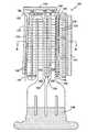
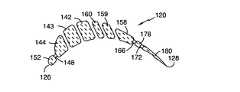
図3、図4に示すように、セラミックコア120が、エーロフォイル20の製造方法で使用され、その内部には中空のキャビティが形成されている。セラミックコア前縁126、セラミックコア後縁128は、エーロフォイル20の前縁26、後縁28にそれぞれ対応する。セラミックコア根本130、先端132は、エーロフォイル根本30、先端32にそれぞれ対応する。チャネル142〜144、158〜160、入口146、162をそれぞれ有するセラミックコア通路140、156は、エーロフォイルのチャネル42〜44、58〜60、入口46、62をそれぞれ有する通路40、56に対応する。エーロフォイルの通路52、78は、セラミックコア内のチャネル152、178に対応する。コア120内の複数のフィンガー148、166、172が、エーロフォイル20内の複数の交差孔48、66、72にそれぞれ対応する。コア先端190が、フィンガー182〜185によってコア通路140、156に取り付けられて、先端132においてコア120を安定させている。外部セラミックハンドル194が、取り扱い用にコア後縁128に取り付けられる。コア延長部196が、根本においてエーロフォイル20への冷却通路を形成する。中心線197〜199が、フィンガー148、166、172の各列を通ってそれぞれ径方向に延びる。
【0009】
タービンブレードおよびベーンが、冷却される最も重要な構成要素の一部ではあるが、燃焼室、ブレード外部空気シールなどの他の構成要素も冷却が必要であり、本発明は、全ての冷却されるタービンハードウェアに対して、さらに実際には、全ての複雑な鋳造物品に対して、適用される。
【0010】
現在、図3、図4に示されるものなどのコアは、セラミック材料から製造されるが、そのようなセラミックコアは、脆弱であり、特に、先進のハードウェア内に複雑で小さな冷却通路を製造するのに使用される先進のコアは、脆弱である。現在のセラミックコアは、製造時、鋳造時に変形、破損しやすい。いくつかの先進の実験的なブレード設計においては、主としてコアの破損のために、得られる鋳造歩留まりは、10%未満となる。
【0011】
従来のセラミックコアは、セラミックスラリーと成形加工されたダイとを用いて成形方法によって製造されており、射出成形およびトランスファー成形技術の両方を用いることができる。パターン材料は、最も一般にはワックスであるが、プラスチック、低融点金属、尿素などの有機化合物も使用されている。シェルモールドは、コロイド状シリカバインダー(結合剤)を用いてセラミック粒子を互いに結合して形成され、このセラミック粒子は、アルミナ、シリカ、ジルコニア、ケイ酸アルミナなどとすることができる。
【0012】
セラミックコアを用いてタービンブレードを製造するインベストメント鋳造方法を、ここで簡潔に説明する。内部冷却通路に望まれる形状を有するセラミックコアを、金属ダイの壁が取り囲むがコアから通常間隔を置くように、金属ダイの中に配置する。ワックスなどの使い捨てパターン材料でダイを満たす。ダイを取り外し、セラミックコアをワックスパターン内に埋め込んだままにする。次に、ワックスパターンをセラミックスラリー中に浸し、その後、スラリーに、より大きな乾燥セラミック粒子を付着させることによって、ワックスパターンの周りに外部シェルモールドを形成する。この工程は、スタッコ塗りと呼ばれる。コアごとスタッコ塗りしたワックスパターンを次に乾燥し、さらに、このスタッコ塗りを繰り返して所望する壁厚のシェルモールドを得る。この時点で、モールドを完全に乾燥し、高温で加熱してワックス材料を取り除くとともにセラミックス材料を強化する。
【0013】
結果として得られるのは、セラミックコアを含むセラミックモールドであり、これらは組み合わさってモールドキャビティを形成する。コアの外部が、鋳造物内に形成される通路を形成し、シェルモールドの内部が、作成される超合金鋳造物の外部寸法を規定することは、理解されるであろう。コアおよびシェルは、鋳造工程には必要だが最終の鋳造構成要素の一部にはならないゲート、押し湯などの鋳造部分も形成できる。
【0014】
ワックスを取り除いた後、シェルモールドおよびコアのアッセンブリによって形成されたキャビティ内へ溶融した超合金材料を注ぎ込み、凝固させる。次に、モールドおよびコアは、機械的および化学的手段の組み合わせによって、超合金鋳造物から取り除く。
【0015】
【発明が解決しようとする課題】
先に言及したように、脆弱性によって、さらに、約0.012−0.015インチ未満の寸法のコアが、許容される鋳造歩留まりで現在は製造できないことによって、現在使用されているセラミックコアでは、鋳造物の設計が制限される。
【0016】
【課題を解決するための手段】
従って、本発明の目的は、向上した機械的特性を有するインベストメント鋳造用のコアを提供することである。
【0017】
本発明のさらなる目的は、現在のセラミックコアより薄い厚みで製造できるコアを提供することである。
【0018】
本発明のさらなる目的は、鋳造工程中の熱衝撃に耐性のあるコアを提供することである。
【0019】
本発明のさらなる目的は、セラミックコア内では得ることができない形状および形態を有するコアを提供することである。
【0020】
本発明のさらなる目的は、費用のかかる道具、方法を用いる必要なしに複雑な設計変更を迅速に実施できるコアを提供することである。
【0021】
本発明に従って、上述した目的を実現するために、さらに、他の利益を得るために、耐熱金属要素を含むコアが説明される。
【0022】
耐熱金属としては、モリブデン、タンタル、ニオブ、タングステンなど、およびこれらの合金などを使用することができる。本発明の目的のために、「耐熱金属」という用語は、上述した耐熱金属に基づく金属間化合物を含むとしても理解されるものである。本発明の一実施態様によれば、これらの耐熱金属のワイヤーを、セラミックコア内に埋め込んで、改善された機械的特性が得られる。
【0023】
本発明の別の実施態様によれば、前もって切断し成形加工して必要なコア形状の少なくとも一部に適合させた耐熱金属のシートの周りに、セラミックコアを形成することができる。
【0024】
本発明の別の実施態様によれば、耐熱ワイヤーまたはシート金属要素を、コアの一部として形成することができ、さらに、鋳造工程中に溶融した金属に曝すことができる。
【0025】
本発明の実施態様によれば、耐熱金属コア構成要素は、耐熱成分が鋳造中に溶融した金属と相互作用するのを防止するように、1層または複数層の保護材料で被覆することができる。
【0026】
本発明の別の実施態様によれば、インベストメント鋳造コアは、複合セラミックおよび耐熱金属構成要素から製造することができる。
【0027】
本発明は、以下の詳細な説明とともに添付の図面を参照することによって理解することができる。
【0028】
【発明の実施の形態】
先に言及したように、従来のセラミックコアは、鋳造物設計に寸法上の制限を課しているので、現在、先進の複雑な超合金物品の設計において制約要因となっている。図5は、本発明のさまざまな実施態様を例示する。図5は、さまざまな例示的耐熱金属要素とともに、図4に示されるような断面図を示す。
【0029】
本発明の実施態様を例示する図5をここで参照すると、破損および変形に対する耐性および強度を与えるように、参考例として1本または複数本の耐熱金属ワイヤー200をセラミックコア内に埋め込むことができる。断面が円形に示されているが、他のワイヤー断面を使用することもできる。
【0030】
コア120の表面セラミックに隣接してワイヤー202を配置することもでき、ワイヤー202によってコア表面輪郭を与えることができる。
【0031】
耐熱金属シート要素を使用することもできる。耐熱金属シート要素204をコア要素の表面に配置することができ、あるいは、成形加工された耐熱シート要素206を、コア要素の半径および角を形成するように成形加工することができ、同様に、耐熱金属要素208が、セラミックコア要素の3つの側面および2つの角を形成できる。耐熱シート金属要素210を、一方の表面から他方の表面に延びるように主としてコア要素内に配置することができ、あるいは、参考例として耐熱コア要素212を、完全にコア要素内に配置することができる。
【0032】
耐熱金属シートを用いなければセラミックから製造できたであろうより薄くて利用できる特性を備えたコア要素を与えるように、後縁128すなわちコア120のいずれか1つまたは複数のコア要素を完全に耐熱金属シート214から形成することができる。
【0033】
抵抗溶接、TIG溶接、ろう付け、拡散接合を含むさまざまな方法を用いて結合させた耐熱金属の複合成形加工されたシート216から、コア要素またはコア全体を製造することもできる。
【0034】
上述した実施態様は例示的なものである。コア設計者は、特定のコア設計を考慮してこれらの実施態様を適切に用いて、いずれか1つまたは複数のこれらの実施態様をコア設計に用いることができる。
【0035】
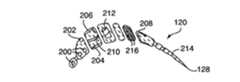
図6は、インベストメント鋳造コア全体の一部を形成するために、薄い耐熱シート金属製の後縁コア要素をどのように使用することができるかを示す。突出する領域224または凹部ポケット226を耐熱金属構成要素に設け、この突出要素の周りまたはポケットの中の少なくとも一方へセラミックを挿入して、セラミック要素と耐熱金属要素との間に機械的ロック(機械的固定)を行うことにより、薄い耐熱金属要素220をセラミック部分222に取り付けることができる。
【0036】
図7は、エーロフォイルの壁内に小さな直径の冷却孔を形成するために、耐熱金属コア要素230をどのように使用することができるかを例示する。図7において、耐熱要素230は、コア232とシェル234との間に延びる。耐熱要素230は、タービン構成要素の壁内に回旋状の冷却通路を形成するものであり、この冷却通路は、従来のコア技術を用いた鋳造によっては形成することができないであろう。
【0037】
Mo、Nb、Ta、Wの耐熱合金は、ワイヤー、シートなどの標準形状で市販されており、これらは、レーザー切断、剪断、穿孔、ホトエッチングなどの方法を用いて、コアを形成するために必要に応じて切断することができる。切断された形状は、曲げ加工およびねじり加工によって変形することができる。標準形状には、空気の乱流を誘発する通路を形成するように波形またはくぼみ(dimple)を付けることができる。通路内に回転ベーンまたはポストを製造するように、シートに孔を打ち抜くことができる。
【0038】
耐熱金属は、一般に高温で酸化されやすく、さらに、溶融した超合金にいくぶん溶けもする。従って、耐熱金属コアは、溶融した金属による腐食および酸化を防止するように、保護被覆を必要とする。耐熱金属コア要素は、保護のために1層または複数層の薄い連続した付着性のセラミック層で被覆することができる。適切なセラミックとしては、シリカ、アルミナ、ジルコニア、酸化クロム(chromia)、ムライト、酸化ハフニウム(hafnia)などがある。耐熱金属とセラミックの熱膨張係数(C.T.E.)は、類似しているのが好ましい。セラミック層は、CVD、PVD、電気泳動法、ゾルゲル法などによって、付着させることができる。
【0039】
多層の異なるセラミックを使用することができる。個々の層は、一般に0.1〜1ミルの厚みとなる。
【0040】
溶融した金属の腐食から保護するためのセラミック被覆と組み合わせて、酸化保護のためにPt、他の貴金属、Cr、Alなどの金属層を、耐熱金属要素に付着させることができる。
【0041】
保護SiO2層を形成するMoSi2およびMo合金などの金属間化合物および耐熱金属合金なども、好ましくなり得る。このような材料は、アルミナなどの非反応性酸化物の良好な付着性を与えると予想される。シリカは酸化物であるが、ニッケル基合金が存在すると非常に反応性となり、他の非反応性酸化物の薄い層で被覆する必要があることは、理解される。しかしながら、同じ特徴によって、シリカは、ムライトを形成するアルミナなどの他の酸化物と容易に拡散接合する。
【0042】
本発明の目的のために、固溶体強化物、析出強化物、拡散強化物などを含む金属は、合金として分類される。
【0043】
Moの合金は、TZM(0.5%Ti、0.08%Zr、0.04%C、残部Mo)を含み、ランタンと化合された(lanthanated)、Wのモリブデン合金は、W−38%Reを含む。
【0044】
上述した合金は、例示であって、限定となることを意図するものではない。
【0045】
鋳造工程が完了した後、シェルとコアは、取り除かれる。シェルは、外部にあり、鋳造物からセラミックを取り壊し機械的手段によって、その後必要応じて、腐食性溶液中に浸漬することを通常含む化学的手段によって、取り除くことができる。
【0046】
従来技術においては、セラミックコアは、腐食性溶液を用いて、通常、オートクレーブ中で高温高圧の条件下で、一般に取り除かれる。
【0047】
本発明のコアが部分的にセラミックである限り、同じ腐食性溶液を用いたコア除去方法を利用することができる。
【0048】
本発明のコアの耐熱金属部分は、酸処理により超合金鋳造物から取り除くことができる。例えば、Moコアをニッケル超合金から取り除くには、本発明者らは、60〜100℃の温度において、40部のHNO3、30部のH2SO4、残部が水からなる溶液、を用いている。
【0049】
相対的に大きな断面積の耐熱金属コアでは、揮発性酸化物を形成するMoを除去するのに熱酸化を用いることができる。小さな断面のMoコアにおいては、熱酸化は効果的でないことが見出された。
【0050】
上述したように、金属Mo、Nb、W、Ta、これらの合金、これらの金属に基づく金属間化合物、に基づくコアが、好ましい。
【図面の簡単な説明】
【図1】ガスタービンエンジンの簡略切欠立面図である。
【図2】図1のガスタービンエンジンのエーロフォイルの拡大断面立面図である。
【図3】本発明による図2のエーロフォイルを製造するための、冷却通路を形成するセラミックコアの立面図である。
【図4】図3の4−4の方向にとったセラミックコアの断面立面図である。
【図5】本発明の実施態様を例示する4−4の方向にとったセラミックコアの断面立面図を示す。
【図6】機械的取り付け機構を示す。
【図7】回旋状の冷却通路を形成するための耐熱金属コアの詳細を示す。
【符号の説明】
10…ガスタービンエンジン
20…エーロフォイル
120…セラミックコア
126…セラミックコア前縁
128…セラミックコア後縁
200…耐熱金属ワイヤー
202…ワイヤー
204…耐熱金属シート要素
206…耐熱シート要素
208…耐熱金属要素
210…耐熱金属シート要素
212…耐熱コア要素
214…耐熱金属シート
216…シート
230…耐熱金属コア要素
232…コア
234…シェル[0001]
BACKGROUND OF THE INVENTION
The present invention relates to an investment casting core, and more particularly to an investment casting core formed at least partially from a refractory metal.
[0002]
[Prior art]
Investment casting is a technique commonly used to form metal components, particularly hollow components, having complex shapes, and is used to produce superalloy gas turbine engine components. While the present invention will be described with respect to the production of superalloy castings, it will be understood that the present invention is not so limited.
[0003]
Gas turbine engines are widely used for aircraft propulsion, power generation, and ship propulsion. Efficiency is the most important objective in all gas turbine engine applications.
[0004]
Improvements in gas turbine engine efficiency can be achieved by operating at higher temperatures, but current operating temperatures are at levels in the turbine section where the superalloy material used has insufficient mechanical properties. As a result, it has become common practice to air cool the components of the hottest part of a gas turbine engine, usually the turbine section. Cooling is accomplished by flowing relatively cool air from the compressor section of the engine through passages in the turbine component to be cooled. Cooling entails a sacrificial cost to engine efficiency, and therefore it is highly desirable to provide enhanced specific cooling to maximize the benefit of cooling from a given amount of cooling air. Will be understood.
[0005]
Referring to FIG. 1, the
[0006]
Both the
[0007]
Referring to FIG. 2, the
[0008]
As shown in FIGS. 3 and 4, the
[0009]
Although turbine blades and vanes are some of the most important components to be cooled, other components such as combustion chambers, blade external air seals also need to be cooled, and the present invention is all cooled It applies to turbine hardware, and indeed to all complex cast articles.
[0010]
Currently, cores such as those shown in FIGS. 3 and 4 are made from ceramic materials, but such ceramic cores are fragile, especially producing complex and small cooling passages in advanced hardware. The advanced core used to do is vulnerable. Current ceramic cores are prone to deformation and breakage during manufacturing and casting. In some advanced experimental blade designs, the resulting casting yield is less than 10%, mainly due to core failure.
[0011]
Conventional ceramic cores are manufactured by a molding method using a ceramic slurry and a molded die, and both injection molding and transfer molding techniques can be used. The pattern material is most commonly a wax, but organic compounds such as plastics, low melting point metals and urea are also used. The shell mold is formed by bonding ceramic particles to each other using a colloidal silica binder (binder), and the ceramic particles may be alumina, silica, zirconia, alumina silicate, or the like.
[0012]
An investment casting method for producing turbine blades using a ceramic core will now be briefly described. A ceramic core having the desired shape for the internal cooling passages is placed in the metal die so that the wall of the metal die surrounds but is normally spaced from the core. Fill the die with disposable pattern material such as wax. Remove the die and leave the ceramic core embedded in the wax pattern. Next, an outer shell mold is formed around the wax pattern by immersing the wax pattern in a ceramic slurry and then depositing larger dry ceramic particles in the slurry. This process is called stucco coating. Next, the stucco-coated wax pattern with the core is dried, and this stucco-coating is repeated to obtain a shell mold having a desired wall thickness. At this point, the mold is completely dried and heated at a high temperature to remove the wax material and strengthen the ceramic material.
[0013]
The result is a ceramic mold that includes a ceramic core, which combine to form a mold cavity. It will be appreciated that the exterior of the core forms a passage formed in the casting and the interior of the shell mold defines the external dimensions of the superalloy casting to be created. The core and shell can also form cast parts such as gates, feeders, etc. that are necessary for the casting process but are not part of the final casting component.
[0014]
After removing the wax, the molten superalloy material is poured into a cavity formed by the shell mold and core assembly and allowed to solidify. The mold and core are then removed from the superalloy casting by a combination of mechanical and chemical means.
[0015]
[Problems to be solved by the invention]
As previously mentioned, due to brittleness, cores with dimensions of less than about 0.012-0.015 inches cannot currently be produced with acceptable casting yields, so currently used ceramic cores The casting design is limited.
[0016]
[Means for Solving the Problems]
Accordingly, it is an object of the present invention to provide an investment casting core having improved mechanical properties.
[0017]
It is a further object of the present invention to provide a core that can be manufactured with a thickness less than current ceramic cores.
[0018]
It is a further object of the present invention to provide a core that is resistant to thermal shock during the casting process.
[0019]
It is a further object of the present invention to provide a core having a shape and form that cannot be obtained within a ceramic core.
[0020]
It is a further object of the present invention to provide a core that can quickly implement complex design changes without the need for costly tools and methods.
[0021]
In accordance with the present invention, a core comprising a refractory metal element is described to achieve the above-described objectives and to obtain other benefits.
[0022]
As the refractory metal, molybdenum, tantalum, niobium, tungsten, or an alloy thereof can be used. For the purposes of the present invention, the term “refractory metal” is also understood to include intermetallic compounds based on the aforementioned refractory metals. According to one embodiment of the present invention, these refractory metal wires are embedded in a ceramic core to provide improved mechanical properties.
[0023]
According to another embodiment of the present invention, a ceramic core can be formed around a sheet of refractory metal that has been previously cut and molded to match at least a portion of the required core shape.
[0024]
According to another embodiment of the present invention, the refractory wire or sheet metal element can be formed as part of the core and further exposed to molten metal during the casting process.
[0025]
According to an embodiment of the present invention, the refractory metal core component can be coated with one or more layers of protective material to prevent the refractory component from interacting with the molten metal during casting. .
[0026]
According to another embodiment of the present invention, the investment casting core can be manufactured from a composite ceramic and a refractory metal component.
[0027]
The invention may be understood by reference to the accompanying drawings in conjunction with the following detailed description.
[0028]
DETAILED DESCRIPTION OF THE INVENTION
As previously mentioned, conventional ceramic cores are currently a limiting factor in the design of advanced complex superalloy articles because they place dimensional constraints on the casting design. FIG. 5 illustrates various embodiments of the present invention. FIG. 5 shows a cross-sectional view as shown in FIG. 4 along with various exemplary refractory metal elements.
[0029]
Referring now to FIG. 5 illustrating an embodiment of the present invention, one or more
[0030]
A
[0031]
Refractory metal sheet elements can also be used. The refractory
[0032]
The trailing
[0033]
The core element or the entire core can also be manufactured from a composite molded
[0034]
The above-described embodiments are exemplary. The core designer can use any one or more of these implementations in the core design, appropriately using these implementations in view of the particular core design.
[0035]
FIG. 6 illustrates how a trailing edge core element made of a thin refractory sheet metal can be used to form part of the entire investment casting core. A
[0036]
FIG. 7 illustrates how the refractory
[0037]
The heat-resistant alloys of Mo, Nb, Ta, and W are commercially available in standard shapes such as wires and sheets, and these are used to form the core using methods such as laser cutting, shearing, drilling, and photoetching. Can be cut if necessary. The cut shape can be deformed by bending and twisting. The standard shape can be corrugated or dimpled to form a passage that induces air turbulence. Holes can be punched into the sheet to produce rotating vanes or posts in the passage.
[0038]
Refractory metals are generally susceptible to oxidation at high temperatures, and are somewhat soluble in molten superalloys. Thus, the refractory metal core requires a protective coating to prevent corrosion and oxidation by the molten metal. The refractory metal core element can be coated with one or more thin continuous adherent ceramic layers for protection. Suitable ceramics include silica, alumina, zirconia, chromium oxide, mullite, hafnia oxide and the like. The refractory metal and the ceramic preferably have similar thermal expansion coefficients (C.T.E.). The ceramic layer can be deposited by CVD, PVD, electrophoresis, sol-gel method or the like.
[0039]
Multiple layers of different ceramics can be used. Individual layers are generally 0.1 to 1 mil thick.
[0040]
In combination with a ceramic coating to protect against corrosion of the molten metal, metal layers such as Pt, other noble metals, Cr, Al, etc. can be attached to the refractory metal element for oxidation protection.
[0041]
Intermetallic compounds such as MoSi2 and Mo alloys that form the protective SiO2 layer and refractory metal alloys may also be preferred. Such materials are expected to give good adhesion of non-reactive oxides such as alumina. Although silica is an oxide, it is understood that it is highly reactive in the presence of nickel-base alloys and needs to be coated with a thin layer of other non-reactive oxides. However, due to the same characteristics, silica is easily diffusion bonded with other oxides such as alumina that form mullite.
[0042]
For purposes of the present invention, metals including solid solution strengtheners, precipitation strengtheners, diffusion strengtheners and the like are classified as alloys.
[0043]
The Mo alloy contains TZM (0.5% Ti, 0.08% Zr, 0.04% C, balance Mo) and is lanthanated with W molybdenum alloy, W-38% Includes Re.
[0044]
The alloys described above are exemplary and are not intended to be limiting.
[0045]
After the casting process is complete, the shell and core are removed. The shell is external and can be removed by mechanical means, usually by demolition of the ceramic from the casting, and then, if necessary, by immersion in a corrosive solution.
[0046]
In the prior art, the ceramic core is generally removed with a corrosive solution, usually under conditions of high temperature and pressure in an autoclave.
[0047]
As long as the core of the present invention is partially ceramic, a core removal method using the same corrosive solution can be utilized.
[0048]
The refractory metal portion of the core of the present invention can be removed from the superalloy casting by acid treatment. For example, to remove a Mo core from a nickel superalloy, we use a solution consisting of 40 parts HNO3 , 30 parts H2 SO4 , and the balance water, at a temperature of 60-100 ° C. ing.
[0049]
For refractory metal cores with a relatively large cross-sectional area, thermal oxidation can be used to remove Mo that forms volatile oxides. Thermal oxidation has been found to be ineffective in small cross-section Mo cores.
[0050]
As mentioned above, cores based on the metals Mo, Nb, W, Ta, alloys thereof and intermetallic compounds based on these metals are preferred.
[Brief description of the drawings]
FIG. 1 is a simplified cutaway elevation view of a gas turbine engine.
FIG. 2 is an enlarged cross-sectional elevation view of the airfoil of the gas turbine engine of FIG.
3 is an elevational view of a ceramic core forming a cooling passage for producing the airfoil of FIG. 2 according to the present invention. FIG.
4 is a sectional elevation view of the ceramic core taken in the direction 4-4 of FIG. 3;
FIG. 5 shows a cross-sectional elevational view of a ceramic core taken in the 4-4 direction illustrating an embodiment of the present invention.
FIG. 6 shows a mechanical attachment mechanism.
FIG. 7 shows details of a refractory metal core for forming a convoluted cooling passage.
[Explanation of symbols]
DESCRIPTION OF
Claims (15)
Translated fromJapanesea)セラミック要素(120)と、
b)このセラミック要素に取り付けられた耐熱金属要素と、
を含み、
耐熱金属要素は、セラミック要素内に完全に埋め込まれるものではないことを特徴とする複合コア。A composite core used in an investment casting process to form an internal passage in an investment casting,
a) a ceramic element (120);
b) a refractory metal element attached to the ceramic element;
Including
A composite core characterized in that the refractory metal element is not completely embedded in the ceramic element.
1)複合コアアッセンブリと、
2)前記コアを取り囲み、前記コアから間隔を置いてキャビティを形成するセラミックシェルモールドと、
3)前記シェルモールド内にあり、前記キャビティに溶融した金属を満たす手段と、
を含み、前記複合コアアッセンブリは、
a)セラミック要素(120)と、
b)このセラミック要素に取り付けられた耐熱金属要素と、
を含み、組み合わされた前記セラミック要素と前記耐熱金属要素との外部輪郭は、ゲート要素および供給要素とともに所望する所定の内部通路の輪郭に実質的に一致し、耐熱金属要素は、セラミック要素内に完全に埋め込まれるものではないことを特徴とするモールド−コアアッセンブリ。A mold-core assembly used in the manufacture of investment castings,
1) a composite core assembly;
2) a ceramic shell mold surrounding the core and forming a cavity spaced from the core;
3) means in the shell mold to fill the cavity with molten metal;
The composite core assembly includes:
a) a ceramic element (120);
b) a refractory metal element attached to the ceramic element;
And the outer contour of the combined ceramic element and refractory metal element substantially matches the desired inner passage contour with the gate element and the supply element, the refractory metal element being within the ceramic element. Mold-core assembly, characterized in that it is not completely embedded.
a)セラミック要素と、
b)このセラミック要素に取り付けられた耐熱金属要素と、
を含み、組み合わされた前記セラミック要素の外部輪郭は、ゲート要素および供給要素とともに所望する所定の内部通路の輪郭に実質的に一致し、耐熱金属要素は、セラミック要素内に完全に埋め込まれるものではないことを特徴とする鋳造物品。A cast article comprising a cast superalloy body including a composite core incorporated therein, the composite core comprising:
a) a ceramic element;
b) a refractory metal element attached to the ceramic element;
The outer contour of the ceramic elements combined with the gate element and the supply element substantially matches the desired inner passage contour, and the refractory metal element is not fully embedded within the ceramic element. Cast articles characterized by not having.
Applications Claiming Priority (2)
| Application Number | Priority Date | Filing Date | Title |
|---|---|---|---|
| US10/001,780US6637500B2 (en) | 2001-10-24 | 2001-10-24 | Cores for use in precision investment casting |
| US10/001780 | 2001-10-24 |
Related Child Applications (1)
| Application Number | Title | Priority Date | Filing Date |
|---|---|---|---|
| JP2006157607ADivisionJP2006247750A (en) | 2001-10-24 | 2006-06-06 | Cores for use in precision investment casting |
Publications (2)
| Publication Number | Publication Date |
|---|---|
| JP2003181599A JP2003181599A (en) | 2003-07-02 |
| JP4137593B2true JP4137593B2 (en) | 2008-08-20 |
Family
ID=21697804
Family Applications (2)
| Application Number | Title | Priority Date | Filing Date |
|---|---|---|---|
| JP2002309155AExpired - Fee RelatedJP4137593B2 (en) | 2001-10-24 | 2002-10-24 | Core for precision investment casting |
| JP2006157607APendingJP2006247750A (en) | 2001-10-24 | 2006-06-06 | Cores for use in precision investment casting |
Family Applications After (1)
| Application Number | Title | Priority Date | Filing Date |
|---|---|---|---|
| JP2006157607APendingJP2006247750A (en) | 2001-10-24 | 2006-06-06 | Cores for use in precision investment casting |
Country Status (11)
| Country | Link |
|---|---|
| US (2) | US6637500B2 (en) |
| EP (2) | EP1306147B1 (en) |
| JP (2) | JP4137593B2 (en) |
| KR (1) | KR100558799B1 (en) |
| CN (1) | CN1200785C (en) |
| AT (1) | ATE383918T1 (en) |
| CA (1) | CA2408815C (en) |
| DE (2) | DE60224631T2 (en) |
| MX (1) | MXPA02010501A (en) |
| RU (1) | RU2240203C2 (en) |
| SG (1) | SG111971A1 (en) |
Families Citing this family (151)
| Publication number | Priority date | Publication date | Assignee | Title |
|---|---|---|---|---|
| US20040115059A1 (en)* | 2002-12-12 | 2004-06-17 | Kehl Richard Eugene | Cored steam turbine bucket |
| US7014424B2 (en)* | 2003-04-08 | 2006-03-21 | United Technologies Corporation | Turbine element |
| US6893210B2 (en)* | 2003-10-15 | 2005-05-17 | General Electric Company | Internal core profile for the airfoil of a turbine bucket |
| US6913064B2 (en)* | 2003-10-15 | 2005-07-05 | United Technologies Corporation | Refractory metal core |
| US7575039B2 (en)* | 2003-10-15 | 2009-08-18 | United Technologies Corporation | Refractory metal core coatings |
| US20050087319A1 (en)* | 2003-10-16 | 2005-04-28 | Beals James T. | Refractory metal core wall thickness control |
| US6929054B2 (en) | 2003-12-19 | 2005-08-16 | United Technologies Corporation | Investment casting cores |
| US6966756B2 (en)* | 2004-01-09 | 2005-11-22 | General Electric Company | Turbine bucket cooling passages and internal core for producing the passages |
| US7216694B2 (en) | 2004-01-23 | 2007-05-15 | United Technologies Corporation | Apparatus and method for reducing operating stress in a turbine blade and the like |
| US6951239B1 (en) | 2004-04-15 | 2005-10-04 | United Technologies Corporation | Methods for manufacturing investment casting shells |
| US7302990B2 (en)* | 2004-05-06 | 2007-12-04 | General Electric Company | Method of forming concavities in the surface of a metal component, and related processes and articles |
| US7216689B2 (en)* | 2004-06-14 | 2007-05-15 | United Technologies Corporation | Investment casting |
| US7172012B1 (en)* | 2004-07-14 | 2007-02-06 | United Technologies Corporation | Investment casting |
| US7144220B2 (en)* | 2004-07-30 | 2006-12-05 | United Technologies Corporation | Investment casting |
| US7278826B2 (en)* | 2004-08-18 | 2007-10-09 | Pratt & Whitney Canada Corp. | Airfoil cooling passage trailing edge flow restriction |
| US7108045B2 (en) | 2004-09-09 | 2006-09-19 | United Technologies Corporation | Composite core for use in precision investment casting |
| US7207374B2 (en)* | 2004-10-26 | 2007-04-24 | United Technologies Corporation | Non-oxidizable coating |
| US7207373B2 (en)* | 2004-10-26 | 2007-04-24 | United Technologies Corporation | Non-oxidizable coating |
| US7134475B2 (en)* | 2004-10-29 | 2006-11-14 | United Technologies Corporation | Investment casting cores and methods |
| EP1920858B1 (en)* | 2004-12-27 | 2009-07-08 | Siemens Aktiengesellschaft | Method for manufacturing a casting mould |
| US8137611B2 (en)* | 2005-03-17 | 2012-03-20 | Siemens Energy, Inc. | Processing method for solid core ceramic matrix composite airfoil |
| US7438527B2 (en) | 2005-04-22 | 2008-10-21 | United Technologies Corporation | Airfoil trailing edge cooling |
| US7393183B2 (en)* | 2005-06-17 | 2008-07-01 | Siemens Power Generation, Inc. | Trailing edge attachment for composite airfoil |
| FR2889088B1 (en) | 2005-07-29 | 2008-08-22 | Snecma | CORE FOR BLADE OF TURBOMACHINE |
| US7185695B1 (en)* | 2005-09-01 | 2007-03-06 | United Technologies Corporation | Investment casting pattern manufacture |
| US7306026B2 (en) | 2005-09-01 | 2007-12-11 | United Technologies Corporation | Cooled turbine airfoils and methods of manufacture |
| US7240718B2 (en)* | 2005-09-13 | 2007-07-10 | United Technologies Corporation | Method for casting core removal |
| US7334625B2 (en)* | 2005-09-19 | 2008-02-26 | United Technologies Corporation | Manufacture of casting cores |
| US20070068649A1 (en)* | 2005-09-28 | 2007-03-29 | Verner Carl R | Methods and materials for attaching ceramic and refractory metal casting cores |
| US7243700B2 (en)* | 2005-10-27 | 2007-07-17 | United Technologies Corporation | Method for casting core removal |
| US7744347B2 (en)* | 2005-11-08 | 2010-06-29 | United Technologies Corporation | Peripheral microcircuit serpentine cooling for turbine airfoils |
| US20070116972A1 (en)* | 2005-11-21 | 2007-05-24 | United Technologies Corporation | Barrier coating system for refractory metal core |
| US7413403B2 (en)* | 2005-12-22 | 2008-08-19 | United Technologies Corporation | Turbine blade tip cooling |
| US8177506B2 (en)* | 2006-01-25 | 2012-05-15 | United Technologies Corporation | Microcircuit cooling with an aspect ratio of unity |
| US7802613B2 (en)* | 2006-01-30 | 2010-09-28 | United Technologies Corporation | Metallic coated cores to facilitate thin wall casting |
| US7413406B2 (en) | 2006-02-15 | 2008-08-19 | United Technologies Corporation | Turbine blade with radial cooling channels |
| US20070221359A1 (en)* | 2006-03-21 | 2007-09-27 | United Technologies Corporation | Methods and materials for attaching casting cores |
| US7861766B2 (en) | 2006-04-10 | 2011-01-04 | United Technologies Corporation | Method for firing a ceramic and refractory metal casting core |
| FR2900850B1 (en)* | 2006-05-10 | 2009-02-06 | Snecma Sa | PROCESS FOR MANUFACTURING CERAMIC FOUNDRY CORES FOR TURBOMACHINE BLADES |
| US7757745B2 (en) | 2006-05-12 | 2010-07-20 | United Technologies Corporation | Contoured metallic casting core |
| US7686065B2 (en)* | 2006-05-15 | 2010-03-30 | United Technologies Corporation | Investment casting core assembly |
| US20080031739A1 (en)* | 2006-08-01 | 2008-02-07 | United Technologies Corporation | Airfoil with customized convective cooling |
| US7690894B1 (en) | 2006-09-25 | 2010-04-06 | Florida Turbine Technologies, Inc. | Ceramic core assembly for serpentine flow circuit in a turbine blade |
| US7753104B2 (en) | 2006-10-18 | 2010-07-13 | United Technologies Corporation | Investment casting cores and methods |
| US20080110024A1 (en)* | 2006-11-14 | 2008-05-15 | Reilly P Brennan | Airfoil casting methods |
| US7938168B2 (en)* | 2006-12-06 | 2011-05-10 | General Electric Company | Ceramic cores, methods of manufacture thereof and articles manufactured from the same |
| US7610946B2 (en)* | 2007-01-05 | 2009-11-03 | Honeywell International Inc. | Cooled turbine blade cast tip recess |
| US7780414B1 (en) | 2007-01-17 | 2010-08-24 | Florida Turbine Technologies, Inc. | Turbine blade with multiple metering trailing edge cooling holes |
| US7866370B2 (en)* | 2007-01-30 | 2011-01-11 | United Technologies Corporation | Blades, casting cores, and methods |
| US7980819B2 (en)* | 2007-03-14 | 2011-07-19 | United Technologies Corporation | Cast features for a turbine engine airfoil |
| US7779892B2 (en)* | 2007-05-09 | 2010-08-24 | United Technologies Corporation | Investment casting cores and methods |
| US8066052B2 (en)* | 2007-06-07 | 2011-11-29 | United Technologies Corporation | Cooled wall thickness control |
| US20090000754A1 (en)* | 2007-06-27 | 2009-01-01 | United Technologies Corporation | Investment casting cores and methods |
| US7845907B2 (en)* | 2007-07-23 | 2010-12-07 | United Technologies Corporation | Blade cooling passage for a turbine engine |
| US7905273B2 (en)* | 2007-09-05 | 2011-03-15 | Pcc Airfoils, Inc. | Method of forming a cast metal article |
| US8083511B2 (en)* | 2007-12-05 | 2011-12-27 | United Technologies Corp. | Systems and methods involving pattern molds |
| US20090197075A1 (en)* | 2008-02-01 | 2009-08-06 | United Technologies Corporation | Coatings and coating processes for molybdenum substrates |
| US7882885B2 (en)* | 2008-02-18 | 2011-02-08 | United Technologies Corporation | Systems and methods for reducing the potential for riser backfilling during investment casting |
| US7942188B2 (en)* | 2008-03-12 | 2011-05-17 | Vent-Tek Designs, Llc | Refractory metal core |
| JP5254675B2 (en)* | 2008-06-16 | 2013-08-07 | 三菱重工業株式会社 | Turbine blade manufacturing core and turbine blade manufacturing method |
| US9174271B2 (en)* | 2008-07-02 | 2015-11-03 | United Technologies Corporation | Casting system for investment casting process |
| US8317461B2 (en)* | 2008-08-27 | 2012-11-27 | United Technologies Corporation | Gas turbine engine component having dual flow passage cooling chamber formed by single core |
| US8100165B2 (en)* | 2008-11-17 | 2012-01-24 | United Technologies Corporation | Investment casting cores and methods |
| US8171978B2 (en) | 2008-11-21 | 2012-05-08 | United Technologies Corporation | Castings, casting cores, and methods |
| US8137068B2 (en) | 2008-11-21 | 2012-03-20 | United Technologies Corporation | Castings, casting cores, and methods |
| US8113780B2 (en) | 2008-11-21 | 2012-02-14 | United Technologies Corporation | Castings, casting cores, and methods |
| US8313301B2 (en)* | 2009-01-30 | 2012-11-20 | United Technologies Corporation | Cooled turbine blade shroud |
| EP2216112A1 (en)* | 2009-02-10 | 2010-08-11 | Siemens Aktiengesellschaft | Nickel based moulded component with a compensation body and method for producing same |
| US8240999B2 (en)* | 2009-03-31 | 2012-08-14 | United Technologies Corporation | Internally supported airfoil and method for internally supporting a hollow airfoil during manufacturing |
| US20110135446A1 (en) | 2009-12-04 | 2011-06-09 | United Technologies Corporation | Castings, Casting Cores, and Methods |
| US20110132562A1 (en)* | 2009-12-08 | 2011-06-09 | Merrill Gary B | Waxless precision casting process |
| GB0921818D0 (en)* | 2009-12-15 | 2010-01-27 | Rolls Royce Plc | Casting of internal features within a product ( |
| US20110182726A1 (en)* | 2010-01-25 | 2011-07-28 | United Technologies Corporation | As-cast shroud slots with pre-swirled leakage |
| US20110204205A1 (en)* | 2010-02-25 | 2011-08-25 | Ahmed Kamel | Casting core for turbine engine components and method of making the same |
| US20110315336A1 (en) | 2010-06-25 | 2011-12-29 | United Technologies Corporation | Contoured Metallic Casting Core |
| US8807198B2 (en) | 2010-11-05 | 2014-08-19 | United Technologies Corporation | Die casting system and method utilizing sacrificial core |
| EP2463044A1 (en)* | 2010-12-09 | 2012-06-13 | Siemens Aktiengesellschaft | Modular ceramic casting core and casting method |
| KR101251475B1 (en) | 2010-12-16 | 2013-04-05 | 한국생산기술연구원 | Shell Core For Casting Using Insert Made From Ceramics And Manufacturing Method Thereof |
| US8251123B2 (en) | 2010-12-30 | 2012-08-28 | United Technologies Corporation | Casting core assembly methods |
| US8302668B1 (en) | 2011-06-08 | 2012-11-06 | United Technologies Corporation | Hybrid core assembly for a casting process |
| CN102489668A (en)* | 2011-12-06 | 2012-06-13 | 辽宁速航特铸材料有限公司 | Method for solving cracking of ceramic core by pre-burying fire-resistant rope |
| FR2984880B1 (en)* | 2011-12-23 | 2014-11-21 | Snecma | METHOD FOR MANUFACTURING A CERAMIC CORE FOR MOBILE DREAM, CERAMIC CORE, MOBILE AUB |
| US9079803B2 (en) | 2012-04-05 | 2015-07-14 | United Technologies Corporation | Additive manufacturing hybrid core |
| FR2990367B1 (en)* | 2012-05-11 | 2014-05-16 | Snecma | TOOLING FOR MANUFACTURING A FOUNDRY CORE FOR A TURBOMACHINE BLADE |
| US20130340966A1 (en) | 2012-06-21 | 2013-12-26 | United Technologies Corporation | Blade outer air seal hybrid casting core |
| US9957817B2 (en) | 2012-07-03 | 2018-05-01 | United Technologies Corporation | Tip leakage flow directionality control |
| US9777582B2 (en) | 2012-07-03 | 2017-10-03 | United Technologies Corporation | Tip leakage flow directionality control |
| US9314838B2 (en)* | 2012-09-28 | 2016-04-19 | Solar Turbines Incorporated | Method of manufacturing a cooled turbine blade with dense cooling fin array |
| US20140102656A1 (en) | 2012-10-12 | 2014-04-17 | United Technologies Corporation | Casting Cores and Manufacture Methods |
| US20140166229A1 (en)* | 2012-12-19 | 2014-06-19 | United Technologies Corporation | Minimization of Re-Crystallization in Single Crystal Castings |
| US20140182809A1 (en)* | 2012-12-28 | 2014-07-03 | United Technologies Corporation | Mullite-containing investment casting core |
| CN103056313A (en)* | 2013-01-05 | 2013-04-24 | 沈阳黎明航空发动机(集团)有限责任公司 | Method for enhancing strength of single crystal blade core by metal core support |
| US9551228B2 (en) | 2013-01-09 | 2017-01-24 | United Technologies Corporation | Airfoil and method of making |
| US9835035B2 (en)* | 2013-03-12 | 2017-12-05 | Howmet Corporation | Cast-in cooling features especially for turbine airfoils |
| CN103240391B (en)* | 2013-04-25 | 2015-05-27 | 西安西工大超晶科技发展有限责任公司 | Method for preparing metal core for investment casting and precision investment casting method for aluminum alloy casting based on metal core |
| WO2015026535A1 (en)* | 2013-08-23 | 2015-02-26 | Siemens Energy, Inc. | Turbine component casting core with high resolution region |
| US9987679B2 (en) | 2013-10-07 | 2018-06-05 | United Technologies Corporation | Rapid tooling insert manufacture |
| US10166599B2 (en) | 2013-11-18 | 2019-01-01 | United Technologies Corporation | Coated casting cores and manufacture methods |
| CN104647586B (en)* | 2013-11-19 | 2017-09-22 | 中国科学院金属研究所 | A kind of preparation method of labyrinth single crystal hollow blade composite ceramic core |
| US10465530B2 (en)* | 2013-12-20 | 2019-11-05 | United Technologies Corporation | Gas turbine engine component cooling cavity with vortex promoting features |
| US10329916B2 (en) | 2014-05-01 | 2019-06-25 | United Technologies Corporation | Splayed tip features for gas turbine engine airfoil |
| CN104014737B (en)* | 2014-05-19 | 2016-11-02 | 沈阳工业大学 | Preparation process of a complex embedded cavity structure ceramic core |
| GB201411332D0 (en) | 2014-06-26 | 2014-08-13 | Rolls Royce Plc | Core positioning |
| FR3030333B1 (en)* | 2014-12-17 | 2017-01-20 | Snecma | PROCESS FOR MANUFACTURING A TURBOMACHINE BLADE COMPRISING A TOP COMPRISING A COMPLEX TYPE BATHTUB |
| CN104475684A (en)* | 2015-01-08 | 2015-04-01 | 广西玉柴机器股份有限公司 | Casting technology of complex shell part |
| FR3034128B1 (en)* | 2015-03-23 | 2017-04-14 | Snecma | CERAMIC CORE FOR MULTI-CAVITY TURBINE BLADE |
| CN105127373B (en)* | 2015-09-10 | 2017-06-23 | 上海大学 | A kind of double wall hollow blade preparation method of hollow ceramic core |
| US9845728B2 (en) | 2015-10-15 | 2017-12-19 | Rohr, Inc. | Forming a nacelle inlet for a turbine engine propulsion system |
| US9968991B2 (en) | 2015-12-17 | 2018-05-15 | General Electric Company | Method and assembly for forming components having internal passages using a lattice structure |
| US10099276B2 (en) | 2015-12-17 | 2018-10-16 | General Electric Company | Method and assembly for forming components having an internal passage defined therein |
| US9987677B2 (en) | 2015-12-17 | 2018-06-05 | General Electric Company | Method and assembly for forming components having internal passages using a jacketed core |
| US10099284B2 (en) | 2015-12-17 | 2018-10-16 | General Electric Company | Method and assembly for forming components having a catalyzed internal passage defined therein |
| US10150158B2 (en) | 2015-12-17 | 2018-12-11 | General Electric Company | Method and assembly for forming components having internal passages using a jacketed core |
| US10099283B2 (en) | 2015-12-17 | 2018-10-16 | General Electric Company | Method and assembly for forming components having an internal passage defined therein |
| US10137499B2 (en) | 2015-12-17 | 2018-11-27 | General Electric Company | Method and assembly for forming components having an internal passage defined therein |
| US10118217B2 (en) | 2015-12-17 | 2018-11-06 | General Electric Company | Method and assembly for forming components having internal passages using a jacketed core |
| US10046389B2 (en) | 2015-12-17 | 2018-08-14 | General Electric Company | Method and assembly for forming components having internal passages using a jacketed core |
| US9579714B1 (en) | 2015-12-17 | 2017-02-28 | General Electric Company | Method and assembly for forming components having internal passages using a lattice structure |
| FR3047767B1 (en)* | 2016-02-12 | 2019-05-31 | Safran | METHOD FOR FORMING DEDUSTING HOLES FOR TURBINE BLADE AND CERAMIC CORE THEREFOR |
| US20170246677A1 (en)* | 2016-02-29 | 2017-08-31 | General Electric Company | Casting with metal components and metal skin layers |
| US20170246679A1 (en)* | 2016-02-29 | 2017-08-31 | General Electric Company | Casting with graded core components |
| US20170246678A1 (en)* | 2016-02-29 | 2017-08-31 | General Electric Company | Casting with first metal components and second metal components |
| US10335853B2 (en) | 2016-04-27 | 2019-07-02 | General Electric Company | Method and assembly for forming components using a jacketed core |
| US10286450B2 (en) | 2016-04-27 | 2019-05-14 | General Electric Company | Method and assembly for forming components using a jacketed core |
| US10458259B2 (en) | 2016-05-12 | 2019-10-29 | General Electric Company | Engine component wall with a cooling circuit |
| KR102209771B1 (en)* | 2016-05-20 | 2021-01-29 | 한화에어로스페이스 주식회사 | Core for casting turbine blade, manufacturing method thereof, and turbine blade using the same |
| US10612389B2 (en) | 2016-08-16 | 2020-04-07 | General Electric Company | Engine component with porous section |
| US10508551B2 (en) | 2016-08-16 | 2019-12-17 | General Electric Company | Engine component with porous trench |
| US10767489B2 (en) | 2016-08-16 | 2020-09-08 | General Electric Company | Component for a turbine engine with a hole |
| US10766065B2 (en) | 2016-08-18 | 2020-09-08 | General Electric Company | Method and assembly for a multiple component core assembly |
| US20180161852A1 (en)* | 2016-12-13 | 2018-06-14 | General Electric Company | Integrated casting core-shell structure with printed tubes for making cast component |
| GB201701365D0 (en)* | 2017-01-27 | 2017-03-15 | Rolls Royce Plc | A ceramic core for an investment casting process |
| US10596621B1 (en) | 2017-03-29 | 2020-03-24 | United Technologies Corporation | Method of making complex internal passages in turbine airfoils |
| US10556269B1 (en) | 2017-03-29 | 2020-02-11 | United Technologies Corporation | Apparatus for and method of making multi-walled passages in components |
| US10695826B2 (en)* | 2017-07-17 | 2020-06-30 | Raytheon Technologies Corporation | Apparatus and method for investment casting core manufacture |
| FR3072415B1 (en)* | 2017-10-17 | 2020-11-06 | Safran Aircraft Engines | HOLLOW TURBINE BLADE WITH REDUCED COOLING AIR INTAKE |
| FR3080051B1 (en)* | 2018-04-13 | 2022-04-08 | Safran | CORE FOR THE FOUNDRY OF AN AERONAUTICAL PART |
| WO2019245563A1 (en)* | 2018-06-21 | 2019-12-26 | Florida Turbine Technologies, Inc. | Process for refining features in an additive manufactured part and manufactured part with refined features |
| US11433990B2 (en) | 2018-07-09 | 2022-09-06 | Rohr, Inc. | Active laminar flow control system with composite panel |
| US11015457B2 (en) | 2018-10-01 | 2021-05-25 | Raytheon Technologies Corporation | Multi-walled airfoil core |
| NL2022372B1 (en) | 2018-12-17 | 2020-07-03 | What The Future Venture Capital Wtfvc B V | Process for producing a cured 3d product |
| FR3113254B1 (en)* | 2020-08-06 | 2022-11-25 | Safran | Protection against oxidation or corrosion of a hollow superalloy part |
| US11813665B2 (en)* | 2020-09-14 | 2023-11-14 | General Electric Company | Methods for casting a component having a readily removable casting core |
| US11220914B1 (en)* | 2020-09-23 | 2022-01-11 | General Electric Company | Cast component including passage having surface anti-freckling element in turn portion thereof, and related removable core and method |
| CN112676534A (en)* | 2020-12-09 | 2021-04-20 | 航天海鹰(哈尔滨)钛业有限公司 | Process method for producing small-size titanium alloy casting with complex inner cavity by using metal core |
| CN112916811B (en)* | 2021-01-22 | 2023-05-16 | 成都航宇超合金技术有限公司 | Casting method of hollow turbine blade with air film hole |
| US11440146B1 (en)* | 2021-04-22 | 2022-09-13 | Raytheon Technologies Corporation | Mini-core surface bonding |
| US12203386B2 (en) | 2022-02-18 | 2025-01-21 | Rtx Corporation | Compressor-turbine rotating assembly with integral cooling circuit(s) |
| CN115108818B (en)* | 2022-07-21 | 2024-03-19 | 中国联合重型燃气轮机技术有限公司 | A raw material for a low shrinkage and low deflection silicon-based ceramic core and its preparation method |
| CN116809853B (en)* | 2023-06-03 | 2025-09-26 | 中国兵器装备集团第五九研究所有限公司 | A method for preparing wax pattern of special-shaped castings |
| CN118957457B (en)* | 2024-10-16 | 2025-01-10 | 河北北方铸业有限公司 | A kind of heating riser material for water glass investment mold and preparation method thereof |
Family Cites Families (16)
| Publication number | Priority date | Publication date | Assignee | Title |
|---|---|---|---|---|
| US3957104A (en)* | 1974-02-27 | 1976-05-18 | The United States Of America As Represented By The Administrator Of The United States National Aeronautics And Space Administration | Method of making an apertured casting |
| IT1096996B (en)* | 1977-07-22 | 1985-08-26 | Rolls Royce | METHOD FOR THE MANUFACTURE OF A BLADE OR BLADE FOR GAS TURBINE ENGINES |
| CH640441A5 (en)* | 1979-09-10 | 1984-01-13 | Hans Schneider | METHOD FOR PRODUCING CASTING PIECES BY PRECISION CASTING. |
| US4487246A (en)* | 1982-04-12 | 1984-12-11 | Howmet Turbine Components Corporation | System for locating cores in casting molds |
| US4596281A (en)* | 1982-09-02 | 1986-06-24 | Trw Inc. | Mold core and method of forming internal passages in an airfoil |
| JPS62173053A (en)* | 1986-01-27 | 1987-07-29 | M C L:Kk | Production of hollow casting |
| JPH0698459B2 (en) | 1986-08-06 | 1994-12-07 | マツダ株式会社 | Core for pressure casting and manufacturing method thereof |
| GB2205261B (en)* | 1987-06-03 | 1990-11-14 | Rolls Royce Plc | Method of manufacture and article manufactured thereby |
| GB9120161D0 (en) | 1991-09-20 | 1991-11-06 | Johnson Matthey Plc | New pinning wire products |
| US5394932A (en) | 1992-01-17 | 1995-03-07 | Howmet Corporation | Multiple part cores for investment casting |
| US5295530A (en)* | 1992-02-18 | 1994-03-22 | General Motors Corporation | Single-cast, high-temperature, thin wall structures and methods of making the same |
| US5599166A (en) | 1994-11-01 | 1997-02-04 | United Technologies Corporation | Core for fabrication of gas turbine engine airfoils |
| RU2094163C1 (en)* | 1995-12-28 | 1997-10-27 | Всероссийский научно-исследовательский институт авиационных материалов | Composite ceramic core |
| US5947181A (en)* | 1996-07-10 | 1999-09-07 | General Electric Co. | Composite, internal reinforced ceramic cores and related methods |
| JPH1052736A (en)* | 1996-08-09 | 1998-02-24 | Honda Motor Co Ltd | Method for producing hollow casting by lost wax method |
| DE19821770C1 (en)* | 1998-05-14 | 1999-04-15 | Siemens Ag | Mold for producing a hollow metal component |
- 2001
- 2001-10-24USUS10/001,780patent/US6637500B2/ennot_activeExpired - Lifetime
- 2002
- 2002-10-18CACA002408815Apatent/CA2408815C/ennot_activeExpired - Fee Related
- 2002-10-21KRKR1020020064107Apatent/KR100558799B1/ennot_activeExpired - Fee Related
- 2002-10-21SGSG200206371Apatent/SG111971A1/enunknown
- 2002-10-23DEDE60224631Tpatent/DE60224631T2/ennot_activeExpired - Lifetime
- 2002-10-23DEDE60239112Tpatent/DE60239112D1/ennot_activeExpired - Lifetime
- 2002-10-23ATAT02257358Tpatent/ATE383918T1/ennot_activeIP Right Cessation
- 2002-10-23EPEP02257358Apatent/EP1306147B1/ennot_activeExpired - Lifetime
- 2002-10-23EPEP07004509Apatent/EP1834717B1/ennot_activeExpired - Lifetime
- 2002-10-23RURU2002128179/02Apatent/RU2240203C2/ennot_activeIP Right Cessation
- 2002-10-24JPJP2002309155Apatent/JP4137593B2/ennot_activeExpired - Fee Related
- 2002-10-24CNCNB021463492Apatent/CN1200785C/ennot_activeExpired - Fee Related
- 2002-10-24MXMXPA02010501Apatent/MXPA02010501A/enactiveIP Right Grant
- 2003
- 2003-07-31USUS10/631,605patent/US20040020629A1/ennot_activeAbandoned
- 2006
- 2006-06-06JPJP2006157607Apatent/JP2006247750A/enactivePending
Also Published As
| Publication number | Publication date |
|---|---|
| EP1834717B1 (en) | 2011-02-02 |
| ATE383918T1 (en) | 2008-02-15 |
| CN1200785C (en) | 2005-05-11 |
| DE60224631D1 (en) | 2008-03-06 |
| US20040020629A1 (en) | 2004-02-05 |
| MXPA02010501A (en) | 2004-07-30 |
| EP1306147B1 (en) | 2008-01-16 |
| RU2240203C2 (en) | 2004-11-20 |
| EP1834717A3 (en) | 2008-10-01 |
| JP2006247750A (en) | 2006-09-21 |
| CA2408815C (en) | 2008-02-12 |
| EP1834717A2 (en) | 2007-09-19 |
| DE60224631T2 (en) | 2008-12-24 |
| SG111971A1 (en) | 2005-06-29 |
| US6637500B2 (en) | 2003-10-28 |
| US20030075300A1 (en) | 2003-04-24 |
| KR20030033942A (en) | 2003-05-01 |
| CA2408815A1 (en) | 2003-04-24 |
| CN1419979A (en) | 2003-05-28 |
| JP2003181599A (en) | 2003-07-02 |
| EP1306147A1 (en) | 2003-05-02 |
| KR100558799B1 (en) | 2006-03-14 |
| DE60239112D1 (en) | 2011-03-17 |
Similar Documents
| Publication | Publication Date | Title |
|---|---|---|
| JP4137593B2 (en) | Core for precision investment casting | |
| US7270170B2 (en) | Investment casting core methods | |
| US10781716B2 (en) | Blade outer air seal cooling scheme | |
| EP1634665B1 (en) | Composite core for use in precision investment casting | |
| US8113780B2 (en) | Castings, casting cores, and methods | |
| EP3381585B1 (en) | Apparatus for and method of making multi-walled passages in components | |
| JP2007307618A (en) | Method for manufacturing combination investment casting core, and investment casting core | |
| JPH07286503A (en) | High efficiency gas turbine | |
| US11014152B1 (en) | Method of making complex internal passages in turbine airfoils |
Legal Events
| Date | Code | Title | Description |
|---|---|---|---|
| A131 | Notification of reasons for refusal | Free format text:JAPANESE INTERMEDIATE CODE: A131 Effective date:20051206 | |
| A601 | Written request for extension of time | Free format text:JAPANESE INTERMEDIATE CODE: A601 Effective date:20060303 | |
| A602 | Written permission of extension of time | Free format text:JAPANESE INTERMEDIATE CODE: A602 Effective date:20060308 | |
| A521 | Request for written amendment filed | Free format text:JAPANESE INTERMEDIATE CODE: A523 Effective date:20060525 | |
| A02 | Decision of refusal | Free format text:JAPANESE INTERMEDIATE CODE: A02 Effective date:20070807 | |
| A521 | Request for written amendment filed | Free format text:JAPANESE INTERMEDIATE CODE: A523 Effective date:20071205 | |
| A911 | Transfer to examiner for re-examination before appeal (zenchi) | Free format text:JAPANESE INTERMEDIATE CODE: A911 Effective date:20071211 | |
| A131 | Notification of reasons for refusal | Free format text:JAPANESE INTERMEDIATE CODE: A131 Effective date:20080108 | |
| A521 | Request for written amendment filed | Free format text:JAPANESE INTERMEDIATE CODE: A523 Effective date:20080403 | |
| TRDD | Decision of grant or rejection written | ||
| A01 | Written decision to grant a patent or to grant a registration (utility model) | Free format text:JAPANESE INTERMEDIATE CODE: A01 Effective date:20080527 | |
| A01 | Written decision to grant a patent or to grant a registration (utility model) | Free format text:JAPANESE INTERMEDIATE CODE: A01 | |
| A61 | First payment of annual fees (during grant procedure) | Free format text:JAPANESE INTERMEDIATE CODE: A61 Effective date:20080604 | |
| R150 | Certificate of patent or registration of utility model | Free format text:JAPANESE INTERMEDIATE CODE: R150 | |
| FPAY | Renewal fee payment (event date is renewal date of database) | Free format text:PAYMENT UNTIL: 20110613 Year of fee payment:3 | |
| LAPS | Cancellation because of no payment of annual fees |