JP4137249B2 - Surgical instrument for forming a knot - Google Patents
Surgical instrument for forming a knotDownload PDFInfo
- Publication number
- JP4137249B2 JP4137249B2JP30330698AJP30330698AJP4137249B2JP 4137249 B2JP4137249 B2JP 4137249B2JP 30330698 AJP30330698 AJP 30330698AJP 30330698 AJP30330698 AJP 30330698AJP 4137249 B2JP4137249 B2JP 4137249B2
- Authority
- JP
- Japan
- Prior art keywords
- suture
- cartridge
- knot
- trigger
- surgical instrument
- Prior art date
- Legal status (The legal status is an assumption and is not a legal conclusion. Google has not performed a legal analysis and makes no representation as to the accuracy of the status listed.)
- Expired - Lifetime
Links
- 238000001356surgical procedureMethods0.000claimsdescription15
- 230000004044responseEffects0.000claimsdescription3
- 210000001519tissueAnatomy0.000description65
- 238000003860storageMethods0.000description17
- 238000000034methodMethods0.000description16
- 230000015572biosynthetic processEffects0.000description10
- 230000008569processEffects0.000description7
- 238000006243chemical reactionMethods0.000description5
- 238000002674endoscopic surgeryMethods0.000description5
- 239000002184metalSubstances0.000description5
- 210000003811fingerAnatomy0.000description4
- 210000003813thumbAnatomy0.000description4
- 238000003780insertionMethods0.000description3
- 230000037431insertionEffects0.000description3
- 230000033001locomotionEffects0.000description3
- 239000004033plasticSubstances0.000description3
- 229920003023plasticPolymers0.000description3
- 230000003187abdominal effectEffects0.000description2
- 230000008901benefitEffects0.000description2
- 230000000694effectsEffects0.000description2
- 238000005516engineering processMethods0.000description2
- 238000002347injectionMethods0.000description2
- 239000007924injectionSubstances0.000description2
- 238000001746injection mouldingMethods0.000description2
- 230000009545invasionEffects0.000description2
- 238000004519manufacturing processMethods0.000description2
- 239000000463materialSubstances0.000description2
- 230000007246mechanismEffects0.000description2
- 238000002324minimally invasive surgeryMethods0.000description2
- 229910001220stainless steelInorganic materials0.000description2
- 239000010935stainless steelSubstances0.000description2
- 241000272201ColumbiformesSpecies0.000description1
- IAYPIBMASNFSPL-UHFFFAOYSA-NEthylene oxideChemical compoundC1CO1IAYPIBMASNFSPL-UHFFFAOYSA-N0.000description1
- 230000009471actionEffects0.000description1
- 210000003484anatomyAnatomy0.000description1
- 230000005540biological transmissionEffects0.000description1
- 239000008280bloodSubstances0.000description1
- 210000004369bloodAnatomy0.000description1
- 210000000988bone and boneAnatomy0.000description1
- 238000010276constructionMethods0.000description1
- 238000007796conventional methodMethods0.000description1
- 238000003795desorptionMethods0.000description1
- 238000000605extractionMethods0.000description1
- 230000006872improvementEffects0.000description1
- 230000003993interactionEffects0.000description1
- 230000014759maintenance of locationEffects0.000description1
- 230000013011matingEffects0.000description1
- 238000012978minimally invasive surgical procedureMethods0.000description1
- 239000002991molded plasticSubstances0.000description1
- 230000000399orthopedic effectEffects0.000description1
- 239000005022packaging materialSubstances0.000description1
- 238000004806packaging method and processMethods0.000description1
- 230000000149penetrating effectEffects0.000description1
- 239000004417polycarbonateSubstances0.000description1
- 229920000515polycarbonatePolymers0.000description1
- 238000002360preparation methodMethods0.000description1
- 238000003825pressingMethods0.000description1
- 230000000717retained effectEffects0.000description1
- 238000005070samplingMethods0.000description1
- 238000000926separation methodMethods0.000description1
- 238000009958sewingMethods0.000description1
- 239000003356suture materialSubstances0.000description1
- 230000009466transformationEffects0.000description1
- 230000001960triggered effectEffects0.000description1
Images


Landscapes
- Endoscopes (AREA)
- Surgical Instruments (AREA)
Description
Translated fromJapanese【0001】
【発明の属する技術分野】
この発明は、縫合糸からなる外科結び目の配置を容易にするためのアセンブリに関する。さらに詳細には、この発明は、対象部位への接近が限定されるような最小限度の体内侵入による外科手術中の結び目の形成配置に特に適したようなアセンブリに関する。
【0002】
【従来の技術】
外科手術の主要な技術として、従来から及び今後も、手術中に、縫合糸からなる外科結び目を形成し、その結び目を体内に配置して、組織を縫合する技術が挙げられる。数多くの外科結び目が長期間に亘って開発されてきた。結び目を形成して組織を縫い付ける技術は、外科医が安全にかつ効率的に手術を行うために取得しなければならない重要な技術である。従って、このような技術が広範に開発されている。例えば、「Tissue Approximation in Endoscopic Surgery(内視鏡による外科手術における切開組織の縫合)」、Alfred Cuschieri及びZoltan Szabo著、Times Mirror International Publishers(1995年発行)は、外科手術中に行われる切開組織の縫合を簡素化させるための縫合糸からなる数多くの外科結び目を記載している。
【0003】
外科結び目の技術は、特許文献においても多く開示されている。米国特許第2,012,776号は縫合糸からなる種々の形態のすべり性結び目の配置を簡素化させるための手術用器具を開示している。この米国特許第2,012,776号の発明者であるH.A.Roederは、現在も外科手術において頻繁に用いられている「ローダ結び目(Roeder Knot)」と呼ばれる外科結び目を開発している。さらに最近、米国特許第5,573,286号は、整形外科の分野で特に有用な縫合用撚り糸からなる外科結び目を開示している。この米国特許第5,573,286号に記載されている好適な実施形態においては、結び目が骨に対して適用されている。
【0004】
従来、遠隔操作によって接近可能な外科手術の対象部位内に、外科結び目を形成かつ配置するのは難しく、また、煩瑣であり、さらに信頼性に欠ける場合が多いと見なされていた。そのために、遠隔操作による結び目の配置を簡素化させるための器具が開発されてきた。好ましい方法として、緊密に締め込まれる結び目を形成するのに必要な工程数を減らすために、縫合糸からなる予め形成された結び目ループを用いる方法がしばしば行われている。例えば、米国特許第2,566,625号及び同第3,090,386号は、特に接近が困難な組織の手術において、その組織を縫合、または縛るための縫合糸からなる予め形成された結び目ループを支持するのに適した手術用装置を記載している。
【0005】
さらに最近、特に最小限度の体内侵入による外科手術中の結び目の配置を簡素化させる器具が開発されている。具体的には、米国特許第5,320,629号に、内視鏡による外科手術において切開組織を縫合する際に、縫合糸からなる結び目ループを予め形成し、その結び目ループを手術用装置に配置することによって、結び目ループの締め込みを簡素化する方法が開示されている。独国特許第912619号も米国特許第5,320,629号に開示された装置と同様の装置を開示している。
【0006】
【発明が解決しようとする課題】
このように、外科結び目の技術は十分に開発され、また、遠隔操作によって行われる部位の手術に対して、縫合糸からなる予め形成された結び目ループから緊密な結び目を容易に形成するための手術用装置も開発されているが、まだ検討されるべき問題点がある。それは、具体的に述べると、対象部位への接近が限定されているような外科手術において、例えば、内視鏡による外科手術のような最小限度の体内侵入による手術中において、形成配置される結び目は決まって安全性の乏しいすべり性結び目となる。結び目の安全性が乏しい場合には、縫合された組織は傷を癒すのに十分な期間保持されないことがある。加えて、最小限度の体内侵入による外科手術中において、従来技術の装置に関して述べた縫合糸からなる予め形成された結び目ループは、最終的な結び目の形成のために効率よく締め込むのが困難である。
【0007】
従って、対象部位への接近が限定されているような最小限度の体内侵入による外科手術において、必要とされるのは、外科結び目の形成を容易にするためのアセンブリである。このアセンブリは構成が比較的単純であるべきであり、また部分的に結ばれた状態(不完全な状態)の外科結び目に適合したものであるべきである。このアセンブリはまた、結び目が配置される度毎に一貫して強固な結び目の安全性を得ることができ、未熟な外科医であっても確実にかつ効率的に縫合糸から安全な縫合糸結び目を配置できるように、部分的に結ばれた状態(不完全な状態)の結び目から完全な状態の結び目への変換を容易にする必要がある。加えて、外科結び目を配置するためのこのアセンブリの使用を容易にするために、このアセンブリが種々の手術器具に対して、特に内視鏡器具に対して容易に適合(レトロフィット)可能であれば、望ましいであろう。さらに加えて、このアセンブリを使用して複数の結び目を配置できるように、第1の結び目を形成配置した後に、第2の部分的に結ばれた状態の結び目をアセンブリに再び装填することができれば有用であろう。
【0008】
さらに、必要とされるものは、縫合糸カートリッジアセンブリを手術用器具に容易に装填できるようにする装置である。具体的には、外科分野の現状を発展させるものは、縫合糸カートリッジアセンブリに収容された縫合糸から手術用結び目を形成配置する(すなわち配備する)ための手術用器具に、外科医が縫合糸カートリッジアセンブリを装填するのを補助し、また、使い果たした第1の縫合糸カートリッジアセンブリがこの手術用器具から取り出された後に第2の縫合糸カートリッジアセンブリを容易に再装填するのを補助するような装置であろう。そのような装置が、針の縫合糸への取付け時に使用者が針を取り扱う必要を無くすように設計され、また、他の包装材料と共に使用される時にその縫合糸カートリッジの出荷と保管のために好適な容器であるように設計されれば、有利であろう。
【0009】
さらに、(特に体腔内への接近が極めて制限される内視鏡外科手術時に)遠隔操作により完全な状態の結び目を容易に形成することができる手術用器具が提供されるとすれば、非常に望ましいであろう。特に、体内の組織、縫合糸または針(所望されるものは何であれ)を遠隔操作し、部分的に結ばれた状態の結び目(すなわち不完全な状態の結び目)から完全に結ばれた状態の結び目の形成を容易にするための作動手段(アクチュエータ)と共に、ハンドルアセンブリを有する手術用器具が提供されるとすれば望ましいであろう。さらに具体的には、必要とされるものは、完全な状態の結び目の形成のために、体内の組織、縫合糸または針の遠隔操作を制御するための第1の作動手段と、縫合糸の遠隔操作を制御制御するための第2の作動手段を有するハンドルアセンブリである。
【0010】
【課題を解決するための手段】
この発明は、完全に結ばれた状態の結び目を手術時に形成して体の組織を縫合するための手術用器具に係るものである。この手術用器具は縫合糸カートリッジと、カートリッジキャリアと、把持用ジョーと、ハンドルアセンブリと、クロージャー管とを備える。
【0011】
この手術用器具の縫合糸カートリッジは、その手術用器具の遠位端に位置する。この縫合糸カートリッジは、部分的に結ばれた状態の結び目が遠位端に形成された縫合糸を収容する。
【0012】
この手術用器具のカートリッジキャリアもまた、その手術用器具の遠位端に位置する。このカートリッジキャリアは上記縫合糸カートリッジを受ける。
【0013】
この手術用器具の把持用ジョーは、上記カートリッジキャリア内の上記縫合糸カートリッジに対向する。この把持用ジョーは、上記縫合糸カートリッジから離れた開放位置から上記縫合糸カートリッジに隣接する閉鎖位置まで移動可能である。
【0014】
この手術用器具のハンドルアセンブリは上記縫合糸カートリッジから離されている。このハンドルアセンブリはこの手術用器具の近位端に位置する。このハンドルアセンブリはこの手術用器具を操作するためのグリップを有する。このハンドルアセンブリはまた、上記把持用ジョーの上記開放位置から上記閉鎖位置までの移動を行わせるための第1作動手段も有する。さらに、このハンドルアセンブリは、縫合糸の近位端に機能的に接続された第2作動手段も有する。この第2作動手段が作動すると、上記縫合糸の近位端が近位方向に引かれ、上記部分的に結ばれた状態の結び目から完全に結ばれた状態の結び目が形成されて体の組織が縫合される。
【0015】
この手術用器具のクロージャー管は、上記カートリッジキャリアを上記ハンドルアセンブリに連結する。このクロージャー管は、上記第1作動手段の作動に応答して、近位位置から遠位位置まで移動可能である。クロージャー管がその近位位置にある時は、この手術用器具の上記把持用ジョーがその開放位置に位置する。逆に、クロージャー管がその遠位位置にある時は、上記把持用ジョーがその閉鎖位置にある。
【0016】
重要な点は、この手術用器具のハンドルアセンブリの第1作動手段と、第2作動手段がそれぞれ、使用者をして、体組織または縫合糸を把持するための把持用ジョーを開いたり閉じたりすることと、完全に結ばれた状態の結び目を形成するために縫合糸を機能的に引くことを可能とすることである。この発明の手術用器具はこれら2つの非常に望ましい機能を行うことができ、これにより対象の体構造への直接の接近が非常に制約されている場合も、内視鏡により、部分的に結ばれた状態の結び目から完全に結ばれた状態の結び目を形成し配置することをさらに容易に行えるようにする。この第1作動手段は、この結び目の適正な配置のため、体組織または縫合糸を適切に操作できるように把持用ジョーを移動させるものである。この初期操作が完了したら、続いて、第2作動手段が作動して、対象の体組織の縫合のため、部分的に結ばれた状態の結び目を所望の完全に結ばれた状態の結び目に変換することができる。
【0017】
この発明の手術用器具は、完全に結ばれた状態の結び目を形成して体組織を縫合することが必要であるか、あるいは望ましい、どのような手術においても使用することができる。広い意味で、この発明の手術用器具は内視鏡手術だけでなく開放手術にも使用できる。しかしながら、この発明の手術用器具は、対象組織への直接の接近が非常に制限された内視鏡用途に特に適している。
【0018】
【発明の実施の形態】
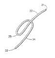
図1乃至図6は、一定長さの縫合糸から、いかにして部分的に結ばれた状態の外科結び目が形成され得るかを例示している図である。このようにして形成された不完全な状態の外科結び目は、後述するこの発明の種々の実施形態を実施するのに用いることができる。言うまでもなく、他の不完全な状態の外科結び目も用いることができる。
【0019】
図1に示される縫合糸30は、現在用いられている、或いは今後開発され得る如何なる縫合材料から構成されてもよい。縫合糸としては、単一縫合糸、または3本以上の糸で編まれた多重縫合糸が挙げられる。縫合糸は、その縫合糸が用いられる具体的な組織の縫合例によるが、その縫合糸の構成に関わらず、吸収性さらに詳細には生物学的な吸収性を有しない材料からなるとよい。
【0020】
一定長さの縫合糸30は、近位端31と遠位端32を有している。さらに、近位端31に隣接して、近位部33を有している。同様に、遠位端32に隣接して、遠位部34を有している。
【0021】
図2に示されるように、縫合糸30の遠位部34を操ることによって、第1ループ35が形成される。図3を参照して、縫合糸30の近位部33を固定したままで、遠位部34を操ることによって、第1ループ35の周囲に、ほぼその第1ループ35を横切るように巻きつく第2ループ36が形成される。同様に、図4に示されるように、第3ループ37及び第4ループ38が第1ループ35の周囲に形成される。第2,第3及び第4ループ36,37,38は互いにほぼ平行であり、第1ループ35をほぼ横切るように配向している。この部分的に結ばれた状態の外科結び目の記述を簡素化するため、これらの第2,第3及び第4ループ36,37,38は集合的に「結び目ループ」と称することもある。結び目ループの数は、結び目が用いられる具体的な用途によって変更されてもよい。例示された実施形態においては、第2,第3及び第4ループ36,37,38は第1ループ35を保持する共通ループコア39を形成する。
【0022】
図5を参照して、緩やかに形成された結び目は縫合糸30の遠位部34に張力を付加させることによって緊密に締め込まれる。その場合、第2,第3及び第4ループ36乃至38は第1ループ35に接して締め込まれ、その結果、第1ループ35は共通ループコア39内に安全に保持される。
【0023】
図6に示されるように、縫合糸30の遠位端32と遠位部34を第1ループ35内に通すことによって、組織縫合ループ40が形成される。
【0024】
外科結び目を形成するに、図6の不完全な状態に結ばれる結び目を形成してから、縫合糸30の近位部33に張力を図7において矢印によって示される近位方向に沿って付加させる。この外科結び目の形成を容易にするために、好ましくは、外科医が指先で結び目ループの近位側を抑えながら張力を縫合糸30の近位部33に付加させるとよい。或いは、下記の実施形態において説明するように、結び目ループを適切な位置に保持するための器具を用いることもできる。張力が付加されると、第1ループ35は結び目の共通ループコア39内に引き込まれはじめる。そして、この第1ループ35のループの大きさが図6に示される状態から十分に縮小され、その縮小されたループによって縫合糸30の遠位部34が捕獲される。縫合糸30の近位部33に近位方向の張力がさらに継続的に付加されると、縫合糸30の第1ループ35とその第1ループ35によって捕獲された遠位部34が共通ループコア39内に引き込まれる。縫合糸30のこの第1ループ35と遠位部が第4ループ38から外方に現れると、プツッというユーザの耳に聞こえる程度の音が生じ、その音によって、ユーザは完全な状態の外科結び目が形成されたことを知ることができる。
【0025】
「血液」結び目と呼ばれることもある、図6に例示される不完全な状態に結ばれている結び目は、この発明の実施に用いる完全な状態に結ばれる非すべり性外科結び目への変換に好適であるが、前述の文献に記載された他のすべり性結び目を用いることもできる。他の不完全な状態に結ばれている結び目にこの発明を適用させるための鍵となる特性は、縫合糸を通過させる共通ループコア(図6の例では共通ループコア39)の形成である。他の不完全な状態に結ばれている結び目として、例えば、「The Encyclopedia of Knots and Fancy Ropewark, R.Graumont & J.Hensel 著Fourth Edition, Cornell Maritime Press」を参照する。この本の第71頁,第83頁,第87頁及び第102頁に作品第102号,第185号,第227号及び第349号として部分的に結ばれた状態の結び目の適切な例が示されている。
【0026】
図8に示されるように、完全な状態の外科結び目は非すべり性結び目41である。第1ループ35は消滅し、第4ループ38に隣接して縫合糸の遠位部34の一部である遠位ループ42が形成される。結果的に、組織の縫合に用いられる組織縫合ループ40は強固にかつ安全に固定される。なお、縫合された組織は拡張すなわち互いに離れるように引っ張られるので、その張力がループ40に付加されて非すべり性結び目41がさらに締め込まれるという有利な結果が得られる。
【0027】
図9及び図10において、図1乃至図6に示された部分的に結ばれた状態の結び目をコア管43の周囲に形成する例が示されている。このコア管43を用いることによって、部分的に結ばれた状態の結び目を図8に示された完全な状態の非すべり性結び目に容易に変換させることができるのみならず、その部分的に結ばれた状態の結び目を容易に被縫合組織に隣接して配置させることができる。コア管43は近位端44と遠位端45を有している。手術用針46が縫合糸30の遠位端32に取り付けられている。縫合糸30の近位部33はコア管43内を貫通している。縫合糸30の長さはコア管43の長さよりも長く、縫合糸30の近位部33がコア管43の近位端44から外方に延出している。また、縫合糸30の十分に長い部分(遠位部34)がコア管43の遠位端45から外方に延びているので、コア管43の遠位端45の周囲に部分的に結ばれた状態の結び目を形成することができる。具体的には、第1ループ35とそれに続く結び目ループ(第2,第3及び第4ループ36,37,38)がコア管43の遠位端45の周囲に形成されている。いったん結び目ループが形成されると、その結び目ループをコア管43の遠位端45の周囲を締め込むために、縫合糸30の遠位部34に張力が付加される。
【0028】
コア管43の周囲に不完全な状態で部分的に締め込まれた結び目を、図11に例示される縫合糸カートリッジ47内に装填させることができる。縫合糸カートリッジ47は細長の本体48を有している。縫合糸カートリッジ47はまた、上面78と底面79も有している。コア管43を受容するための管スロット49が、上面78と底面79間でカートリッジ47の本体48内に設けられている。また、この本体は一対の脱離ショルダー51を有する結び目凹部50を備えている。管スロット49の近位端52から近位方向に延びているのは縫合糸スロット53である。同様に、管スロット49の遠位端54からカートリッジ本体48の遠位端に向かって延びているのはループスロット55である。図11においてL1 で示されるコア管43の長さは、図11においてL2 で示される管スロット49の長さよりも短い。
【0029】
部分的に結ばれた状態の結び目がコア管43の周囲に形成されると、結び目ループがコア管43の遠位端45の周囲に巻き付けられ、縫合糸の自由な近位部33はコア管43の近位端44から外方に延出し、部分的に結ばれた状態の結び目の第1ループ35はコア管43の遠位端45から外方に延出する。このようなコア管43が上面78と底面79間でカートリッジ本体の管スロット49内に装填されると、結び目ループは結び目凹部50内に置かれてその結び目凹部50の脱離ショルダー51に当接する。縫合糸30の近位部33の一部はカートリッジ本体48内に設けられた縫合糸スロット53内に置かれ、縫合糸30の近位部33の残りの部分はカートリッジ本体48の近位端52から外方に延出する。同様に、部分的に結ばれた状態の結び目の第1ループ35と縫合糸30の遠位端32がループスロット55内に受容される。第1ループ35の大部分と縫合糸30の遠位部34は、カートリッジ本体48の底面79から下がっている。図13に最もよく例示されている基本位置において、コア管43の遠位端45は管スロット49の遠位端54に隣接している。管スロット49はコア管43よりも長いので、コア管43は管スロット49の近位端52に向かって近位方向に滑動することができる。この基本位置において、結び目は凹部50内に閉じ込められている。こうして、外科医は、結び目を早い段階で偶発的に締め込んでしまうおそれもなく、針46と縫合糸30の遠位部34を容易に操ることができる。
【0030】
コア管43がカートリッジ本体48内の管スロット49に装填されると、図12に示されるように、カートリッジ天板56がカートリッジ本体48の上面78上に取り付けられる。カートリッジ天板56が取り付けられると、コア管43はカートリッジ47内に十分に密封される。
【0031】
コア管43が縫合糸カートリッジ47内に十分に密封されると、コア管43の周囲に巻き付けられた部分的に結ばれた状態の結び目は、図14及び図15に例示されるように、所定の体組織を縫合するのに用いられる。第1段階として、縫合糸カートリッジ47が縫合される体組織57に隣接して配置される。続いて、手術用針46が組織内を貫通し、第1ループ35内を通過し、組織縫合ループ40が形成される。組織縫合ループ40の大きさは、縫合される体組織57の互いに対向する部分に適当な張力が付加されるように調整される。いったん結び目が完全に締め込まれて非すべり性結び目が形成されると、組織縫合ループ40は強固に固定され、それ以上の調整はできなくなる。組織縫合ループ40が適当な大きさに形成された後、縫合糸30の近位部33に近位方向の張力が図15の矢印によって示される方向に付加される。近位部33に十分な張力が付加されることによって、以下に述べるように、完全な状態の結び目が形成される。
【0032】
すなわち、好都合なことに、縫合糸30の近位部33に張力が付加されると、第1ループ35が引っ張られ、その結果、近位方向の力がコア管43の遠位端45に対して付加され、コア管43が図15に示されるように近位方向に滑る。結び目ループは結び目凹部50内の脱離ショルダー51に当接しているので、コア管43が近位方向に滑っても固定されたままである。コア管43が管スロット49の近位端52に隣接する位置にまで滑動すると、結び目ループはコア管43の遠位端45から脱離される。これによって、結び目は完全な状態に形成され、ユーザはカートリッジ天板56を取り外して、縫合糸30の残りの近位部33と遠位部34を切除して、コア管43を取り外す。或いは、近位部33に付加される張力を解放してカートリッジ47を近位方向に引っ張って、コア管43内に含まれている縫合糸30の近位部33と遠位部34の一部を凹部50から遠位方向に延出させることによって、カートリッジ天板56を取り外すことなく縫合糸30の近位部33と遠位部34をカートリッジ47から露出させることができる。
【0033】
縫合糸カートリッジ47は、従来の切開手術器具及び内視鏡的検査器具に容易に適用でき、外科結び目の形成を容易に行えるという利点がある。この縫合糸カートリッジ47は使い捨てでもよいし、または何人かの患者に対して用いてもよい。何人かの患者に用いるときには、部分的に結ばれた状態の結び目を周囲に巻き付けた複数の使い捨てコア管が縫合糸カートリッジに順次装填することによって、組織を縫合するための数多くの外科結び目を単一の縫合糸カートリッジを用いて提供することができる。
【0034】
このコア管の概念を利用した別の例では、部分的に結ばれた状態の結び目がコア管の周囲に巻き付けられ、組織を縫合するための完全な状態の非すべり性結び目への変換を容易にする。この類似の実施形態を図21乃至図23に示す。この実施形態が図9乃至図15に例示された実施形態と異なる一つの特徴は、コア管が傾斜された遠位端を有する点にある。説明を簡単にするために、図21〜図23において、図9乃至図15に示す部品と類似の部品は同じ参照符号で示す。
【0035】
部分的に結ばれた状態の結び目の別の例を図16と図17に示す。結び目は近位端59と遠位端60を有する縫合糸58からなる。手術用針61が遠位端60に取り付けられている。縫合糸の近位端59を固定したままの状態で縫合糸の遠位端60を操ることによって、その結び目が形成される。コアループ62,近位ループ63及び第1ループ64が最初に形成される。近位ループ63は結び目の第1端部70にあり、第1ループ64は結び目の反対側端部71にある。コアループ62はそれらの第1端部と反対側端部間に位置している。この好適な実施形態においては第2,第3及び第4ループ65,66,67からなる結び目ループが近位ループ63及び第1ループ64の周囲に形成されている。これらの結び目ループが共通ループコア68を形成する。コアループ62は共通ループコア68内に位置している。結び目ループの近位端を保持したままの状態で縫合糸の遠位端60に張力が付加されると、結び目ループが締め付けられる。さらに具体的に述べると、結び目ループが第1ループ64、近位ループ63及びコアループ62の周囲に締め付けられる。そして、結び目ループが締め付けられると、図17に示されるように、第1ループ64、コアループ62及び近位ループ63は結び目ループ内に安全に保持され、部分的に結ばれた状態の結び目が形成される。
【0036】
図17に特に示されているように、コアループ62は共通ループコア68から結び目の第1端部70に向かって延出する自由な近位端59を有している。コアループ62はまた、共通ループコア68から結び目の反対側端部71に向かって反対方向に延出するループ端72を有している。コアループ62のループ端72は第1ループ64内に配置されている。
【0037】
図17に示されている部分的に結ばれた状態の結び目は、結び目ループの近位端59を保持しながら近位ループ63に軸方向張力を近位方向に付加することによって、完全な状態の非すべり性結び目に変換させることができる。図1乃至図8において好ましく例示された方法と同様の方法で、第1ループを共通ループコア68内に引き込んで遠位ループを形成することによって、結び目を変換させることができる。好都合なことに、近位ループ63に張力が付加されると、第1ループ64が共通ループコア68内に引き込まれるだけではなく、コアループ62もまた共通ループコア68内に引き込まれる。これは、コアループ62が十分な空間を共通ループコア68内に形成して、第1ループ64が共通ループコア68内を貫通して完全な状態の結び目を形成するのを容易にさせるという利点がある。このように第1ループ64が共通ループコア68内を容易に貫通するので、完全な状態の結び目を形成するために近位ループ63に付加される張力の大きさを減少させることができ、従って、結び目を形成する際のユーザの制御性を向上させることができる。
【0038】
図18乃至図20は、脱離管(コア管)73を用いて、図17に示される部分的に結ばれた状態の結び目から組織を縫合するための完全な状態の結び目に変換させる例を示している図である。図17に示す部分的に結ばれた状態の結び目が形成されると、近位ループ63が脱離管73内を通される。近位ループ63の一部は脱離管73の近位端から外方に延出している。結び目ループが脱離管73の遠位端74に当接するまで、近位ループ63は脱離管73内を通される。ここで重要な点は、脱離管73が傾斜された(すなわちテーパ付きの)遠位端74を有していることである。コアループ62と第1ループ64が管73の傾斜された遠位端74から外方に延出している。脱離管73の遠位端74の開口は結び目ループの径よりも小さい。その結果、近位ループ63に張力が近位方向に付加されても、結び目ループは脱離管73内を通らない。
【0039】
部分的に結ばれた状態の結び目から完全な状態の結び目への変換は、図6に示した結び目の変換に関連して前に述べた方法と実質的に同様の方法で行われる。
【0040】
図19及び図20に示されるように、脱離管73は縫合される体組織75に隣接して配置される。手術用針61が組織75内に通される。手術用針61と縫合糸30の遠位端60が第1ループ64内に導かれることによって、組織縫合ループ76が形成される。ここでも、結び目が完全に形成される前に縫合組織に適当な張力が付加されるように組織縫合ループ76の大きさを調整することが重要である。所定の組織縫合ループ76が形成されると、近位ループ63に張力が図19の矢印によって示される近位方向に付加され、コアループ62と第1ループ64が共通ループコア内に引き込まれる。そして、第1ループ64が第4結び目ループ67から現れて遠位ループ77が形成され、完全な状態の非すべり性結び目が形成される。
【0041】
この発明の実施に用いることのできる縫合糸カートリッジアセンブリの好ましい実施形態を図24乃至図39に示す。この好ましい実施形態は図11乃至図15に示したアセンブリをさらに改良したものであり、コア管に巻き付け、続いて縫合糸カートリッジに装填した部分的に結ばれた状態の結び目を備える。
【0042】
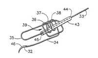
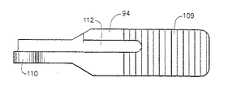
図24,図25を先ず参照すると、好適な縫合糸カートリッジ80は、近位端82と遠位端83を有し、コア管85に巻き付いて部分的に結ばれた状態の結び目84に形成された縫合糸81を備える。この縫合糸81の近位端82はコア管85の近位端から延出しており、縫合糸の第1ループ86はコア管85の遠位端から延出し、手術用針87が縫合糸81の遠位端83に取付けられている。
【0043】
縫合糸カートリッジ80は上面88、下面89、及びコア管85を収容するためのスロット90を有し、コア管85に巻き付けた部分的に結ばれた状態の結び目84をもった縫合糸81を、このカートリッジの上面88と下面89間に備えている。スロット90は縫合糸の部分的に結ばれた状態の結び目84を収容するための結び目凹部91を備え、部分的に結ばれた状態の結び目84は結び目凹部91内の1対の脱離ショルダー92に当接する。コア管85をスロット90内に装填すると、手術用針87と第1ループ86を有する縫合糸81の遠位端83の一部分がカートリッジの下面89から下がる。カートリッジ天板93は縫合糸カートリッジの上面88を覆い、それによりコア管85と縫合糸81の一部分を閉じ込める。
【0044】
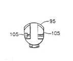
把持用ジョー94がピボットピン(または旋回軸ピン)95で縫合糸カートリッジ80に旋回可能に取付けられていることは重要である。この把持用ジョー94はカートリッジ天板93に対向しており、カートリッジ天板93から離れた開放位置からカートリッジ天板93に隣接する閉鎖位置まで移動可能である。この把持用ジョー94は開放位置に付勢(biased)されている。縫合糸トラック96を有するカートリッジハウジング95も縫合糸カートリッジ80の近位端に取付けられている。
【0045】
ここで図28乃至図32を参照すると、縫合糸カートリッジ80とこの縫合糸カートリッジに一体に取付けられたカートリッジハウジング95の詳細を見ることができる。縫合糸カートリッジ80の遠位端は、カートリッジ天板93を縫合糸カートリッジの上面88に永久的に取り付けるための保持ピン97を備えている。この保持ピン97は「熱頭造(heat-staked)」されてカートリッジ天板93を縫合糸カートリッジ80に取り付ける。縫合糸カートリッジ80の遠位端にはまた、定位ボス98も設けられている。把持用ジョー94を縫合糸カートリッジ80に旋回取付けするピボットピン95を収容するため、ピンオリフィス99がある。ピンオリフィス99を通して収容されたピボットピン95は、カートリッジハウジング95を縫合糸カートリッジ80に固定する役割も果たす。中央口(aperture)100がカートリッジハウジング95の遠位端に設けられ、把持用ジョー94の近位端を収容するための開口となる。またカートリッジハウジング95内には、把持用ジョー94をその開放位置に付勢する捩りばね102(図24及び図33を参照)を収容するための捩りばねスロット101も設けられている。この捩りばね102は上アーム113、捩りループ114、ジョーアーム115を有する。
【0046】
カートリッジハウジング95の縫合糸トラック96は腹部チャンネル103を有し、腹部チャンネル103は、カートリッジハウジング95の近位端まで近位方向に延びる左側縫合糸溝104に合流する。カートリッジハウジング95の近位端には1対の横側縫合糸スロット105がある。横側縫合糸スロット105から続いて、右側縫合糸溝106がカートリッジハウジング95内に埋設されている。このカートリッジハウジング95は1対の離れたフック歯108で囲まれたフックスロット107も備えている。
【0047】
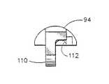
ここで図34乃至図36を参照すると、把持用ジョー94の詳細を示している。この把持用ジョー94は組織、縫合糸あるいは手術用針を把持し易くするため鋸歯状内面109を有する。この把持用ジョー94はジョーラグ(突出部)110を備え、ジョーラグ110は、縫合糸カートリッジ80に対する把持用ジョー94の旋回取付けのためのピボットピン95を収容するジョーオリフィス111を備えている。把持用ジョー94はまた、捩りばね102を収容するためのばねアームスロット112も有する。カートリッジ天板93の近位端は、ばねタブ116を備えている。ばねタブ116は、組立時と結び目形成時に、コア管85を付勢し保持する。
【0048】
好ましい実施形態では、縫合糸カートリッジアセンブリは一人の患者が使用した後は廃棄される使い捨てアセンブリである。縫合糸カートリッジ80とカートリッジハウジング95は好適には生体適合性の射出成形プラスチックから成り、把持用ジョー94は好適には医療等級のステンレス鋼から作られる。あるいはまた、縫合糸カートリッジアセンブリは金属射出成形(MIM)プロセスにより適切な金属から製造することもできるだろう。この金属射出成形(MIM)プロセスは、手術用ステープラーやカッター用の従来のステープルカートリッジを製造するのに適合した従来の製造技術である。
【0049】
図26及び図27は、どのようにしてコア管85を縫合糸カートリッジ80に取り付けるか、どのようにして縫合糸の近位端82を縫合糸トラック96内でカートリッジハウジング95の周囲に巻き付けるかを示す図である。コア管85を縫合糸カートリッジ80のスロット90内に装填すると、手術用針87と縫合糸の遠位端83の一部分をスロット90に通し、部分的に結ばれた状態の結び目84を結び目凹部91に配置する。この結び目凹部91では、部分的に結ばれた状態の結び目84が脱離ショルダー92に当接し、第1ループ86がカートリッジの下面89から下がる。縫合糸の近位端82をカートリッジハウジング95の腹部チャンネル103に通し、カートリッジハウジング95内のアンカー凹部117に出るまで縫合糸トラック96の左側縫合糸溝104、横側縫合糸スロット105及び右側縫合糸溝106に巻き付ける。アンカー凹部117内で縫合糸81の近位端82を結んで結び目アンカー118を形成し、その縫合糸81をカートリッジハウジング95内の固定位置に配置する。図26及び図27を見る際に注目に値するのは、カートリッジ天板93を縫合糸カートリッジの上面88に取付ける場合、そのカートリッジ天板93をさらに保持するため、カートリッジハウジング95と縫合糸カートリッジの上面88との間の合流点にある1対の保持スロット119である。
【0050】
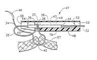
特に好ましい実施形態では、この発明の実施に使用することのできる装填後の縫合糸カートリッジアセンブリが、手術器具121のカートリッジキャリア120内に収容され、結び目の形成配置と、組織、手術用針あるいは縫合糸の把持をさらに容易にする。特に図33を参照すると、カートリッジハウジング95を有する縫合糸カートリッジ80がカートリッジキャリア120内に装填され収容される。このカートリッジキャリア120は該カートリッジアセンブリを収容するためのチャンネル123を形成する1対の収容壁122を有する。収容壁122の各々は上エッジ面124と、その遠位端に鋸歯状エッジ面125を有する。縫合糸カートリッジ80を収容するためのカートリッジキャリア120を有する手術用器具は、クロージャー管126が前に動く時は把持用ジョー94をその閉鎖位置まで付勢し、そしてそのクロージャーが後に動く場合には把持用ジョー94をその開放位置まで付勢するための、往復運動するクロージャー管126を備えることが有利である。そのような手術器具は好適には、カートリッジハウジング95の1対のフック歯108間のフックスロット107に収容されるフック127を備える。フック127が後退する時に、そのフック127は縫合糸カートリッジハウジングの縫合糸トラック96内にある縫合糸の近位端を引き、図11〜図15に示した方法と同様の方法で結び目を形成配置する。
【0051】
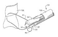
ここで図37乃至図39を参照する。図から分かるように、カートリッジアセンブリがキャリア120内に装填されるとカートリッジキャリアの収容壁122の鋸歯状エッジ面125が縫合糸カートリッジのカートリッジ天板93から突き出し、そして把持用ジョー94がその閉鎖位置にある時にそのジョーの鋸歯状内面109と噛み合う。その際に、これら噛み合う面125,109が組織128(図37)、縫合糸81(図38)、及び手術用針87(図39)の把持を容易にする。従って、この発明の縫合糸カートリッジアセンブリは、部分的に結ばれた状態の結び目から完全な状態の結び目の形成配置を容易にするばかりでなく、組織あるいは、結び目を容易に配置するため手術時に非常に重要となる手術用針を付けた縫合糸の操作をも容易にする。
【0052】
図40乃至図49には、この発明の好適な手術用器具と協働して用いることのできる装填補助装置、ならびにその装填補助装置内に収容された縫合糸カートリッジがその手術用器具のカートリッジキャリアにどのようにして装填されるかを示す。
【0053】
まず図40乃至図42を参照すると、装填補助装置130の詳細が分かる。装填補助装置130は剛性で透明のカートリッジケース131を備え、このカートリッジケース131は、手術用器具のカートリッジキャリアに縫合糸カートリッジが装填され、手術器具のカートリッジアセンブリがその透明なケースから取り出される時の取扱いを容易にしケース内の内容物を容易に観察されるようにするものである。ケース131は基部(base)132と、その基部に対向する上蓋133とから成る。上蓋(top cover)133は取り外し自在に基部132に取り付けられている。上蓋133は遠位ピン134と近位ピン135を備え、これら遠位ピン134と近位ピン135を、ケース131の基部132のそれぞれ対応する遠位ボス136と近位ボス137が受ける。上蓋133を基部132にさらに固定するため、基部132の下位ボス138が上蓋133から延出した対応する低位ピン(図示せず)を受け、ケース支持リブ139もまた上蓋133から延出して基部132と摩擦係合する。
【0054】
カートリッジケース131の基部132と上蓋133間の空洞がカートリッジ保管スペース140を形成する。このカートリッジ保管スペース140は近位リテーナ141と、この近位リテーナから離れた遠位リテーナ142と、これら近位リテーナと遠位リテーナの間のジョー保持レッジ(押縁)143とを備える。カートリッジ保管スペース140は装填補助装置のカートリッジケース131内で縫合糸カートリッジを受けて固定する。
【0055】
カートリッジケース131の基部132と上蓋133はまた、手術手順時に縫合糸カートリッジに収容された縫合糸から縫合糸を形成配置するため手術用器具のカートリッジキャリアの挿入と引出しを可能とするためのキャリア口144も形成する。内部キャリアチャンネル145はキャリア口144とカートリッジ保管スペース140間の通路となり、手術用器具のカートリッジアセンブリはキャリア口144を通して挿入されると、キャリアへカートリッジの装填のためのカートリッジ保管スペース140に入るまで、その内部キャリアチャンネル145を通ることができる。キャリアチャンネル145は、基部(base)132から延出したベース支持レッジ146と、このベース支持レッジと相互に対峙した関係で上蓋(top cover)133から延出したカバー支持リブ147とにより境界がつけられている。手術用器具のカートリッジキャリアの挿入と引出しをさらに容易にするため、入口傾斜路148も設けられている。この入口傾斜路148はキャリア口144からキャリアチャンネル145まで延びている。
【0056】
カートリッジケース131の基部132はパッド149を備え、そのパッド149の上に縫合糸カートリッジの縫合糸が配置される。上蓋133は、その上蓋133が基部132に固定された時に、縫合糸カートリッジの縫合糸をパッド149上の一定位置に保持するための縫合糸リテーナ150を有する。同様に、上蓋133は、その上蓋133がカートリッジケースの基部132に配置された時に、縫合糸カートリッジの縫合糸に取り付けられた手術用針をパッド149上に保持するための針リテーナ151も有する。
【0057】
装填補助装置130のカートリッジケース131内のカートリッジ保管スペース140は縫合糸カートリッジ152を受ける。この縫合糸カートリッジ152は、第1ループ154を持った部分的に結ばれた状態の結び目に形成した縫合糸153と、この縫合糸の遠位端に取り付けられた手術用針155を収容する。縫合糸カートリッジ152は、カートリッジ天板156と、このカートリッジ天板に対向した把持用ジョー157を有する。把持用ジョー157は、ピボットピン158にて、カートリッジ天板156から離れた開放位置からカートリッジ天板156に隣接する閉鎖位置まで旋回移動可能である。この把持用ジョー94は通常はその開放位置に付勢(biased)されている。
【0058】
第1ループ154と縫合糸153は、図42に示すように基部132の外面リ内に保持されている。このように制約されているので、第1ループ154と縫合糸153は、カートリッジキャリアへの縫合糸カートリッジ152の装填時にもつれたり、はさまれたりしない。
【0059】
この発明の実施に好適な縫合糸カートリッジは、図24乃至図39に示したようなアセンブリである。縫合糸カートリッジ152は、その縫合糸カートリッジの近位端が近位リテーナ141に着座するように位置する。その縫合糸カートリッジの遠位端が遠位リテーナ142に着座し、把持用ジョー157がジョー保持レッジ143に対して保持される。縫合糸カートリッジ152をカートリッジ保管スペース140に確実に固定するために、遠位リテーナ142とジョー保持レッジ143間の間隔は、把持用ジョー157がその開放位置と閉鎖位置との間の位置に向くような間隔である。このようにして、ジョー保持レッジ143に対する把持用ジョー157の付勢作用が、縫合糸カートリッジ152をカートリッジ保管スペース140内にしっかりと配置するのを助ける。カートリッジ保管スペース140内の縫合糸カートリッジ152はカートリッジ近位端からカートリッジ遠位端まで下向きに傾いていることも注目に値する。図42に示すような縫合糸カートリッジアセンブリは包装し、ガンマ線照射やエチレンオキサイド曝露のような従来技術を用いて滅菌してもよい。
【0060】
この発明の手術用器具159は、カートリッジケース131から縫合糸カートリッジ152をその器具159に装填し続いてその縫合糸カートリッジ152内に収容された縫合糸から結び目を形成配置する(すなわち配備する)ために、装填補助装置130と協働して使用することができるものである。この手術用器具159は、従来の開放手術用器具に、あるいは最小限侵入手術に適した内視鏡手術用器具に使用することができるが、内視鏡手術用器具であることが好ましい。手術用器具159は、カートリッジケース131のキャリア口144内に挿入しキャリア口144から引き出すことができるとともに、キャリアチャンネル145を通じてカートリッジ保管スペース140まで通すことができるように構成されたカートリッジキャリア160を有することが有利である。カートリッジキャリア160はまた、カートリッジ保管スペース140から縫合糸カートリッジ152を受けることができるように構成されなければならないことは勿論である。手術用器具159は、縫合糸カートリッジのカートリッジ天板156に対して把持用ジョー157を開いたり閉じたりするため、後退位置から伸張位置(すなわち前進位置)まで移動可能なクロージャー管161を有することが好ましい。
【0061】
ここで図43乃至図49を参照すると、装填補助装置のカートリッジケース131のカートリッジ保管スペース140に入れられた縫合糸カートリッジ152を手術用器具159のカートリッジキャリア160に装填する工程のシーケンスが示されている。図43では、カートリッジキャリア160は、キャリア口144に挿入されキャリアチャンネル145を通ることができるように配向される。図44では、カートリッジキャリア160は既にキャリア口144に挿入されており、カートリッジケースのカートリッジ保管スペース140内で縫合糸カートリッジと接触するまで、矢印で図示した装填方向にキャリアチャンネル145を通される。縫合糸カートリッジ152が傾いた向きにある結果、カートリッジキャリア160は、縫合糸カートリッジ152の近位端と遠位端との間の中間地点で縫合糸カートリッジ152と接触する。ここで図45を参照すると、カートリッジキャリア160が遠位方向に移動し、カートリッジ保管スペース140内の遠位リテーナ142と近位リテーナ141から縫合糸カートリッジ152を追い出す。このカートリッジ保管スペース140内でのカートリッジキャリア160の遠位方向の移動と共に、遠位リテーナ142と近位リテーナ141から縫合糸カートリッジ152が追い出されることにより、手術用器具159のカートリッジキャリア160が縫合糸カートリッジ152を受ける。カートリッジキャリア160が遠位方向に移動する時に縫合糸カートリッジ152がそのカートリッジキャリア160内に装填される際に、手術用器具159のクロージャー管161はその後退位置に維持される。上蓋133の縫合糸リテーナ150と針リテーナ151から、パッド149上に着座する縫合糸153と手術用針155に及ぼされる圧力は僅かであるので、装填動作時に縫合糸と針の移動を妨げるものはないことも注目に値する。図46では、いったん手術用器具159のカートリッジキャリア160に縫合糸カートリッジ152が装填されると、手術用器具159のクロージャー管161がその後退位置から前進位置まで移動し、こうして縫合糸カートリッジ152を手術用器具159のカートリッジキャリア160に固定する。
【0062】
図47乃至図49を特に参照すると、手術用器具159の装填後のカートリッジキャリア160が装填補助装置のカートリッジケース131から取り出される。それはカートリッジキャリア160を、カートリッジケース131のカートリッジ保管スペース140、キャリアチャンネル145及びキャリア口144から、図47に矢印で図示した抜取方向に単に引き出すことにより、取り出される。
【0063】
縫合糸153と手術用針155がカートリッジケース131から外へ自由に通ることができるように、カートリッジケース131内のキャリアチャンネル145を境界付けるベース支持レッジ146とカバー支持リブ147間に、小さなギャップ(間隙)があることが有利である(ギャップを見るには図41を参照)。同様に、縫合糸153と手術用針155がカートリッジケース131から外へ容易に通ることができるように、カートリッジケースの基部132内でパッド149上に着座する縫合糸153と手術用針155に及ぼされる圧力は最小限であることが有利である。
【0064】
手術用器具159のカートリッジキャリア160に装填された縫合糸カートリッジ152に収容された縫合糸から結び目を形成配置するために、いったん手術用器具159を使用したら、外科医または手術室の助手は使用済みのカートリッジを抜き取り、それを捨てることができる。追加の手術用結び目を形成配置する必要がある場合は、外科医または手術室の助手は、手術用器具159のカートリッジキャリア160へ第2の縫合糸カートリッジを容易に装填できるように、この発明の装填補助装置をもう一つ調達するだけでよい。
【0065】
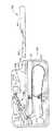
図50乃至図60は、この発明の好適な実施形態である手術用器具121を示す。図51をまず参照すると、手術用器具121のハンドルアセンブリ300は、近位端193と遠位端194を有するグリップ192と、第1作動手段としてのトリガー180と、第2作動手段としてのレバー220と、グリップ192の各側に左解放ボタン240、右解放ボタン238(図50参照)と、トリガーラッチ281とを備える。クロージャー管126がグリップ192の近位端193に取り付けられており、クロージャー管126は第1作動手段としてのトリガー180の作動により制御され、グリップ192内を長手方向に摺動するのが制約されている。このクロージャー管126の機能により、図43〜図49に示したような工程による縫合糸カートリッジアセンブリ80(図24参照)の装填と抜取り、並びに図37乃至図39に示したような把持用ジョー94の開放と閉鎖が可能である。第2作動手段としてのレバー220が作動すると、図15,図19,図23に示したような縫合糸の近位部33を軸方向に引くことにより部分的に結ばれた状態の結び目が形成配置され、その結果、図8に示すような完全に結ばれた状態の結び目が生じる。左解放ボタン240と右解放ボタン238は、同時作動により、縫合糸カートリッジアセンブリ80の装填と抜取りのためのトリガー180の開放が可能である。トリガーラッチ281は、トリガー180が完全に作動した後にグリップ192に対してトリガー180を保持し、次にトリガー180が完全に作動した後にグリップ192からトリガー180を解放する。
【0066】
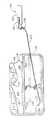
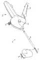
図51乃至図56は手術用器具121の所期の動作のシーケンスを示しており、これを次に説明する。再び図51を参照すると、手術用器具121は、初期使用に先立って縫合糸カートリッジアセンブリを収容し得るような配置にある。図51に関連する図52から分かるように、カートリッジキャリア120は空であり、クロージャー管126の遠位端はカートリッジキャリア120の最遠位置と最近位置の間の中間付近(以下「中間位置」と称する)に位置している。図53は装填配置/抜取配置にある手術用器具121を示す図である。左解放ボタン240と右解放ボタン238が同時に押されてトリガー180が図示の開放位置にはね返り、次に、クロージャー管126が近位方向に後退する。縫合糸カートリッジアセンブリ80はカートリッジキャリア120内に配置するが容易であり、装填補助装置130を用いて図43乃至図45に示したシーケンスが次に行われることになる。図54では、トリガー180が図示のような中間位置まで作動してクロージャー管126が図53に示すような中間位置まで遠位方向に移動している。この時、縫合糸カートリッジアセンブリ80がカートリッジキャリア120内に捕捉され、そのカートリッジを収容した手術用器具121が装填補助装置130から引き出される。手術用器具121の使用における次の工程は図55に示すような体腔内にその手術用器具の遠位端を導入することであり、把持用ジョー94が内視鏡カニューレ298を通して挿入されるには把持用ジョーがその閉鎖位置にある必要があるので、外科医の助手は、装填補助装置130からその器具121を取り出してこれを外科医に手渡す前に、トリガー180を、トリガー180がグリップ192に対してラッチされトリガーラッチ281によりそこに保持されるまで、完全に閉じる。この装填シーケンスは図46乃至図49に示されている。いったん外科医が手術用器具121の遠位部分を、内視鏡カニューレ298を通して体腔内に導入したら、トリガー180の完全な作動により、グリップ192からトリガーが解放され、次にクロージャー管126が近位方向に後退すると共に把持用ジョー94が開く。手術用器具121はこの時、組織128(図37参照)、縫合糸81(図38参照)あるいは手術用針87(図39参照)の把持と操作のために使用することができるようになる。図56は、組織128を縫合するため結び目を形成配置する際の手術用器具121を示す図である。レバー220は、内部止めに到達していて結び目を形成配置するまで、外科医の母指もしくは指により下向きの弧(arc)に作動される。このレバー220の作動は、この弧(arc)に沿っていずれの地点でも止められ、レバー220はその位置を維持する。この構成により、外科医は、適正に縫合糸を引っ張って結び目を配置するために、縫合糸とその縫合糸が固定される組織を操作したり点検したりすることができる。いったんレバー220が完全に作動され、外科医の母指もしくは別の指がそのレバーから持ち上げられると、レバー220はばね力によりそのスタート位置に戻る。手術用器具121は次に、トリガー180が閉鎖位置にあっても閉鎖位置になくても体腔内から引き出され、新たな第2の縫合糸カートリッジアセンブリの装填のために備える。
【0067】
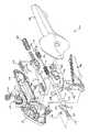
図50は、クロージャー管126と共にハンドルアセンブリ300の構成要素の分解斜視図である。グリップ192の外殻は左グリップカバー190と右グリップカバー200から成り、両方ともポリカーボネートのような剛性の医療等級プラスチックから製造するのが好ましい。これらのカバーは、その内部に構成要素を支持し整合させるため、複数のボスとリブを有する。トリガー180とレバー220は、左グリップカバー190と右グリップカバー200間で支持され、上述したように動く。ピニオン210とラック270とクロージャー管260は金属から製造してもよいが、各種の射出成形した剛性の医療等級プラスチックから製造するのが好ましい。以下のハンドルアセンブリ300の構成要素、すなわち、ベースアンカー280、トリガーラッチばね282、板ばねつめ284、レバーばね290、管ばね230、管ラッチ234、カップラーばね242、ラックばね250、ワッシャー252、保持リング254、及び縫合糸引きロッド246は、プラスチックから製造してもよいが、ステンレス鋼のような金属から製造するのが好ましい。
【0068】
図50をさらに参照するとともにここで図57も参照すると、ハンドルアセンブリ300の構成要素は目で見ることができ、図51及び図54に対応する作動配置にある。トリガー180はその中間位置にあり、右グリップカバー200から突き出たピボットボス184で支持されている。トリガーフォーク182は、カップラー凹部264(図50参照)に挿入されたフランジ171(図50参照)によりクロージャー管126に取り付けられたクロージャーカップラー(クロージャー連結手段)260の左押しアーム262と右押しアーム263をそれぞれ支承する。カップラーばね242は、そのカップラーから伝達される長手方向の力が該カップラーばねのばね定数により制限されるように、フランジ171とカップラー凹部264の近位端間で圧縮される。このことは、外科医が把持用ジョー157を完全に閉鎖させない組織または別の対象物を把持しようとする時にクロージャー管126の遠位端により把持用ジョー157に過剰な力がかからないことを保証するものである。上述した一連の構成要素は、クロージャー管126の近位端で捕捉され一部圧縮された管ばね230により近位方向に付勢(biased)される。この管ばね230はグリップの近位端193の内壁を押す。クロージャーカップラー260は管ラッチ234により長手方向の中間位置に保持され、それらは管ラッチ234の3つの穴235に押し込まれた3つのカップラーポスト261により連結される。管ラッチ234は、管ラッチ右端232が右グリップカバー200から突き出た右ラッチリブ198と係合し、同様に管ラッチ左端233が左グリップカバー190にある鏡像関係の左ラッチリブ(図示せず)と係合するように、横方向に開いたばねとなっている。右解放ボタン238と左解放ボタン240はそれぞれ管ラッチ右端232と管ラッチ左端233の上に位置する。右解放ボタン238と左解放ボタン240は「ウィッシュボーン」式に「鳩尾形状」ボタンアンカー239に連結され、このボタンアンカー239は、右グリップカバー200と左グリップカバー190からそれぞれ延出した右ボタンリテーナ195とその鏡像関係の左ボタンリテーナ(図示せず)に嵌め込まれている。
【0069】
図57をさらに参照すると、レバー220がそのスタート位置で図示され、右グリップカバー200から突き出たレバーピボットボス222で支持されている。また右グリップカバー200から突き出たピニオンピボットボス212で支持されたピニオン210の複数のピニオン小ギア歯213と、複数のレバーギア歯224が噛み合う。左右のグリップカバー190,200から突き出たグリップカバーリブ218間で長手方向の移動が制約されたラック270の複数のラックギア歯272と、複数のピニオン大ギア歯216が噛み合う。レバーばね290はラック270の近位端274で捕捉され、ラックばね室近位端277と左右のグリップカバー190,200から突き出た2つの基底リブ295,294との間で初期の分離力を作用させるため一部圧縮されている。これら基底リブ295,294は「C形状」であり、ハンドルアセンブリ300の中心軸まで延びている。基底リブ295,294は、ラック270の遠位端274の隙間(clearance)を与えてラック270の近位方向へ長手方向の移動を可能とするように、一緒になって穴を形成する。レバーばね290の予め荷重された力はラック270を遠位方向に付勢し、上述した駆動要素を通じてレバー220へ伝達され、こうしてレバー220をそのスタート位置に留めるように付勢する。
【0070】
図58をここで参照すると、ハンドルアセンブリ300が、手術用器具に縫合糸カートリッジアセンブリ80が装填または抜取りされる時の図53に対応する作動配置で図示されている。クロージャーカップラー260の緩みのため、トリガー180はハンドルアセンブリの300の長手軸線から離れる方向に完全に振れている。このハンドルの配置を、外科医またはその外科医の助手は母指とこれに対峙する指を使って左右の解放ボタン240,238を同時に絞めることにより得ており、これにより管ラッチ234が圧縮され、次に管ラッチ234が左右のラッチリブ198,199から離れる。これにより、管ばね230がクロージャーカップラー260の端に近位方向の力を及ぼす。これにより、クロージャーカップラー260、管ラッチ234、クロージャー管126が直ちに近位方向に動き、これによりトリガー180を完全に開放する。このトリガー180の開放は、トリガーフォーク182が左右のグリップカバー190,200のトリガー止め188にぶつかることにより制限される。トリガー180が開放するためには、使用者は解放ボタン238,240を押圧する間、トリガー180を保持する必要はない。この構成が具体的に、片手操作でありながらクロージャー管126の後退を故意の工程とすることを意図するものである。これは、縫合糸カートリッジアセンブリ80を体腔内に不意に開放することは望ましくないからである。
【0071】
使い果たされた、すなわち「発射」された縫合糸カートリッジアセンブリ80がカートリッジキャリア120から引き抜かれ、新たな縫合糸カートリッジアセンブリが図43乃至図49に示した工程により装填されると、次は、管ラッチ234を左右のラッチリブ199,198と再係合させるようにトリガー180を十分に絞め、縫合糸カートリッジアセンブリ80がカートリッジアセンブリ120に捕捉される位置にクロージャー管126を再配置させることによって、ハンドルアセンブリ300を図59に示すような「形成配置準備完了」モードにする。これが完了すれば、外科医はレバー220の作動時にトリガー180をこの位置に留めるか、トリガー180を完全に閉鎖してグリップ192に対してラッチさせるか、あるいは上述の位置間のどこかの位置にトリガー180を保持するかを選ぶことができる。
【0072】
図60では、トリガー180が一部絞められる間にレバー220が完全に作動されたが、トリガーフック186がトリガーラッチばね282でラッチされるにはまだ不十分である時の状態が示されている。レバー220を図示のように下向きに動かすと、上述した一連のギア相互作用により、ラック270が長手方向に近位方向に動き、レバーばね290を圧縮する。ラックばね室276に収容されたラックばね250も同様に近位方向に動いているので、ラックばね250は、縫合糸引きロッド246に取り付けられた保持リング254に当接したワッシャー252に対して近位方向に長手方向の力を伝達する。この縫合糸引きロッド246は、縫合糸近位端82と係合するフック127(図33)に取り付けられている。したがって、縫合糸引きロッド246が近位方向に動くと、図11乃至図15に示した方法とぼぼ同様な方法で結び目が形成配置される。このため、ラック270から縫合糸引きロッド246まで伝達される全部の力は、ラックばね250のばね定数とラックばね250がラックばね室の遠位端276とワッシャー252間で圧縮された距離との積に、ラックばね250の予め荷重された力を加えた和に等しいという点で、ラックばね250は力制限手段として作用する。本発明のこの力制限手段の構成が、縫合糸の過度の引張り(これが生ずる場合には結び目が完全に形成配置される以前に縫合糸を破断してしまう)を防止するのを助ける。ただし、上記全部の力が伝達されるのは、縫合糸引きロッド246の抵抗力がラックばね250の予め荷重された力に等しいか、またはこれを超える場合に限られる。この抵抗力は、組織の接近縫合時に外科医により及ぼされた助ける83の引張りの張力と角度によって主に変動する。この抵抗力が最大となるのは、通常、結び目が図7,図8に示したような非すべり性結び目に変換される時である。このため、ばねがその密着高さにまでつぶれてしまう状態(これが生ずる場合には外科医がレバー220に過度の力を及ぼして縫合糸近位部分33を破断してしまう)が起こらないように、ラックばね250は、結び目の変換を行うのに充分な長手方向の力を伝達するような寸法や予備荷重にされていることが重要である。ラックばね250は、それをある長さだけさらに圧縮するのに要する力が縫合糸の引張り強さに近いか、またはこれを超える状態の寸法や予備荷重にされるべきではない。なぜなら、この場合には、上述の力制限の構成を用いて縫合糸の破断を防止することができないからである。上述の力の伝達時にも、カートリッジキャリア120は、右グリップカバー200の内壁の凹部281に挿入されたベースアンカー280への取付けにより(図50参照)、グリップ192に対して基底付けられ動かない。
【0073】
図60をさらに参照すると、ラック270には「T形状」板ばねつめ284がラック270に取り付けられているのが分かる。レバー220の作動時に、この板ばねつめ284の横方向のアームが、左右のグリップカバー190,200の内面に成形された複数の歯206(図50参照)と係合し、外科医がレバー220からの圧力を解放すべきである場合には、ラック270は、レバーのスタート位置とストップ位置間の多数の不連続な地点で、その長手方向の位置を維持できる。板ばねつめ284が成形歯206の端を超えて動き、そのため板ばねつめ284が成形歯206とから離れてしまい、そしてレバー220をそのスタート位置まで戻すような位置にはね返る前に、レバー220は完全に作動しなければならない。この時、外科医は、レバースプリング290の力によりラック270が遠位方向に動いて、レバー220をそのスタート位置に戻すことができるように、レバー220は解放しなければならない。このレバー保持の構成は、皮膚用ステープラーのような他の手術用装置への使用についてよく知られている。
【0074】
上述したハンドルアセンブリは好適な実施形態のものであり、その所期の機能を達成するためには、他のグリップ形状やアセンブリ内機構が可能であることが認識されるであろう。例えば、ハンドルアセンブリは「ピストルグリップ」(ピストル状グリップ)を有してもよいし、また、母指とこれに対峙する指の挿入のためグリップとトリガーに開口を設けてもよい。さらに、ハンドルアセンブリを静止したままで、この手術用器具の遠位端部分がその長手軸線の周りを回転するようにすることもできる(この回転のためロッキング機構を設けてもよい)。上述の手術用器具は、主に材料選択や組立方法によっては、一人の患者の使用により使い捨て可能としたり、再使用可能としたり、この二つの組合せとしてよい。
【0075】
以上この発明の種々異なる実施形態はこの発明の代表的な実施形態であるが、これらの実施形態は例示にすぎない。この発明の範囲は、これらの実施形態によって、あるいは当業者の想到し得る他の特定の実施形態によって限定して解釈されるべきではなく、請求の範囲の記載により解釈されるべきである。
【0076】
なお、この発明の具体的な実施態様は以下の通りである。
(А) 完全に結ばれた状態の結び目を手術時に形成して体の組織を縫合するための手術用器具において、
a) 部分的に結ばれた状態の結び目が遠位端に形成された縫合糸を収容する、上記器具の遠位端にある縫合糸カートリッジと、
b) 上記縫合糸カートリッジを受けるための、上記器具の遠位端にあるカートリッジキャリアと、
c) 上記縫合糸カートリッジから離れた開放位置から上記縫合糸カートリッジに隣接する閉鎖位置まで移動可能な、上記カートリッジキャリア内の上記縫合糸カートリッジに対向する把持用ジョーと、
d) i) 上記器具を操作するためのグリップ、
ii) 上記把持用ジョーの上記開放位置から上記閉鎖位置までの移動を行わせるための第1作動手段、及び
iii) 上記部分的に結ばれた状態の結び目から完全に結ばれた状態の結び目が形成されて体の組織が縫合されるように、縫合糸の近位端を近位方向に引くための、上記縫合糸の近位端に機能的に接続された第2作動手段を有する、上記縫合糸カートリッジから離されて上記器具の近位端に位置するハンドルアセンブリと、
e) 上記第1作動手段の作動に応答して、上記把持用ジョーがその開放位置に位置する近位位置から上記把持用ジョーはその閉鎖位置にある遠位位置まで移動可能な、上記カートリッジキャリアを上記ハンドルアセンブリに連結するクロージャー管とを備えた手術用器具。
(1)前記縫合糸カートリッジは、前記クロージャー管がその近位位置にある時に前記カートリッジキャリア内に装填され、前記クロージャー管がその近位位置と遠位位置間の中間位置まで動かされた時に前記カートリッジキャリア内に固定される実施態様(A)に記載の器具。
(2)完全に結ばれた状態の結び目を形成するように前記第2作動手段が作動される時に前記縫合糸が破断するのを防止するため、前記第2作動手段と前記縫合糸近位端と共に協働可能な第1の付勢要素をさらに備えた実施態様(A)に記載の器具。
(3)前記クロージャー管をその近位位置から遠位位置まで動かすように前記第2作動手段が作動される時に過荷重から保護を行うため、前記第1作動手段と共に協働可能な第2の付勢要素をさらに備えた実施態様(2)に記載の器具。
(4)前記第1作動手段は前記ハンドルアセンブリに旋回可能取付けされたトリガーであり、前記グリップから離れた第1のトリガー位置から前記グリップに隣接した第2のトリガー位置まで移動可能であり、前記クロージャー管は前記第1作動手段がその第1トリガー位置にある時にその近位位置にあり、前記第2作動手段がその第2トリガー位置にある時にその遠位位置にある実施態様(A)に記載の器具。
(5)前記第1作動手段は前記第1トリガー位置と前記第2トリガー位置間の第3のトリガー位置まで移動可能であり、前記第1作動手段がその第3トリガー位置にある時に前記クロージャー管はその中間位置にある実施態様(4)に記載の器具。
【0077】
(6)前記第2作動手段は前記ハンドルアセンブリに旋回可能取付けされたレバーであり、前記レバーは、前記縫合糸端を引いて完全に結ばれた状態の結び目を形成するように第1のレバー位置から第2のレバー位置まで旋回される実施態様(4)に記載の器具。
(7)前記グリップが使用者の手のひらに置かれた時に前記トリガーと前記レバーを作動させるため、前記器具の前記ハンドルアセンブリは片手操作に適している実施態様(6)に記載の器具。
(8)前記トリガーはその第1トリガー位置に向けて付勢され、前記クロージャー管はその近位位置に向けて付勢され、前記レバーはその第1レバー位置に向けて付勢される実施態様(7)に記載の器具。
(9)前記ハンドルアセンブリから突き出た解放ボタンをさらに備え、前記解放ボタンは前記クロージャー管と前記トリガーと共に協動可能であって、前記解放ボタンが前記ハンドルアセンブリに向けて内側に押され前記トリガーがその第2または第3トリガー位置にある時に、前記トリガーはその第1トリガー位置まで動く実施態様(8)に記載の器具。
(10)前記縫合糸カートリッジはその内部にフックスロットを有し、前記縫合糸の近位端は前記フックスロットを横断し、前記レバーは前記ハンドルアセンブリ内に設けられたピニオンに接続された実施態様(6)に記載の器具。
【0078】
(11)前記ハンドルアセンブリ内に設けられ前記ピニオンと共に協動可能なラックと、前記ラックに接続された縫合糸引きロッドとをさらに備えており、前記縫合糸引きロッドは前記ハンドルアセンブリから前記カートリッジキャリアまで延びており、前記縫合糸引きロッドはその遠位端に前記縫合糸カートリッジの前記フックスロットを通じて延びるフックを有しており、前記ピニオンは、前記レバーが前記第1レバー位置から前記第2レバー位置まで旋回される時に前記ラックと前記ラックに接続された縫合糸引きロッドを近位方向に動かし、前記縫合糸引きロッドの前記フックは、前記部分的に結ばれた状態の結び目から完全に結ばれた状態の結び目を形成するように、前記縫合糸カートリッジ内で前記フックスロットを横断する前記縫合糸の近位端を近位方向に引く実施態様(10)に記載の器具。
【0079】
【発明の効果】
以上説明したようにこの発明の縫合糸カートリッジアセンブリによれば、使用者は、この手術用器具のハンドルアセンブリの第1作動手段により、把持用ジョーを開いたり閉じたりして体の組織または縫合糸を把持するためのことができ、また第2作動手段により、縫合糸を機能的に引いて、部分的に結ばれた状態の結び目から完全に結ばれた状態の結び目を形成することができるので、手術対象の体内構造への直接の接近が非常に制約されている場合にも、内視鏡により、部分的に結ばれた状態の結び目から完全に結ばれた状態の結び目を形成し配置することを容易に行うことができる。
この発明の手術用器具は、完全に結ばれた状態の結び目を形成して体組織を縫合することが必要であるか、あるいは望ましい、どのような手術においても使用することができるが、対象組織への直接の接近が非常に制限された内視鏡による手術に特に適している。
【図面の簡単な説明】
【図1】一定長さの縫合糸から部分的に結ばれた状態の結び目を形成する一連の工程を例示する斜視図である。
【図2】一定長さの縫合糸から部分的に結ばれた状態の結び目を形成する一連の工程を例示する斜視図である。
【図3】一定長さの縫合糸から部分的に結ばれた状態の結び目を形成する一連の工程を例示する斜視図である。
【図4】一定長さの縫合糸から部分的に結ばれた状態の結び目を形成する一連の工程を例示する斜視図である。
【図5】一定長さの縫合糸から部分的に結ばれた状態の結び目を形成する一連の工程を例示する斜視図である。
【図6】一定長さの縫合糸から部分的に結ばれた状態の結び目を形成する一連の工程を例示する斜視図である。
【図7】図6に示す部分的に結ばれた状態の結び目を非すべり性外科結び目に変換する工程の斜視図である。
【図8】図6に示した部分的に結ばれた状態の結び目を非すべり性外科結び目に変換する工程の斜視図である。
【図9】縫合糸に取り付けられた手術用針を備える図6に示した部分的に結ばれた状態の結び目をコア管の周囲に形成する例を示す斜視図である。
【図10】縫合糸に取り付けられた手術用針を備える図6に示した部分的に結ばれた状態の結び目をコア管の周囲に形成する例を示す斜視図である。
【図11】図9及び図10に示したコア管の周囲に形成された図6に示した部分的に結ばれた状態の結び目と共に縫合糸カートリッジを例示する分解斜視図である。
【図12】カートリッジ天板が取り付けられた図11に示した縫合糸カートリッジのアセンブリを示す斜視図である。
【図13】図12の線13−13に沿ったアセンブリの断面図である。
【図14】組織を縫合するための部分的に結ばれた状態の結び目からその組織を確実に縫合するための完全な状態の外科結び目を形成する工程を示す、組織の部分断面を含む図13に示したアセンブリの断面図である。
【図15】組織を縫合するための部分的に結ばれた状態の結び目からその組織を確実に縫合するための完全な状態の外科結び目を形成する工程を示す、組織の部分断面を含む図13に示したアセンブリの断面図である。
【図16】一定長さの縫合糸から別の部分的に結ばれた状態の結び目の形成を示す斜視図である。
【図17】一定長さの縫合糸から別の部分的に結ばれた状態の結び目の形成を示す斜視図である。
【図18】脱離管の周囲に形成される図17に示した部分的に結ばれた状態の結び目の斜視図である。
【図19】図18に示したアセンブリを用いて、組織を縫合するための完全な状態の非すべり性外科結び目を形成する例を示す側面図である。
【図20】図18に示したアセンブリを用いて、組織を縫合するための完全な状態の非すべり性外科結び目を形成する例を示す側面図である。
【図21】傾斜されたコア管の周囲に形成される図6に示した部分的に結ばれた状態の結び目から組織を縫合するための完全な状態の非すべり性外科結び目を形成する例を示す図である。
【図22】傾斜されたコア管の周囲に形成される図6に示した部分的に結ばれた状態の結び目から組織を縫合するための完全な状態の非すべり性外科結び目を形成する例を示す図である。
【図23】傾斜されたコア管の周囲に形成される図6に示した部分的に結ばれた状態の結び目から組織を縫合するための完全な状態の非すべり性外科結び目を形成する例を示す図である。
【図24】好ましい縫合糸カートリッジアセンブリの斜視図である。
【図25】コア管に巻かれ、縫合糸カートリッジアセンブリから分離された、好ましい縫合糸カートリッジアセンブリの部分的に結ばれた状態の結び目を示す分解斜視図である。
【図26】縫合糸の遠位端に取付けられた手術用針が縫合糸カートリッジのカートリッジスロットに装填される、図24及び図25の縫合糸カートリッジアセンブリを組み立てる初めの工程を示す分解斜視図である。
【図27】縫合糸の近位端が縫合糸カートリッジに取付けたカートリッジハウジングに固定される、コア管のカートリッジスロットへの装填に続く次の工程を示す斜視図である。
【図28】カートリッジハウジングを有する図24の好ましい縫合糸カートリッジアセンブリの平面図である。
【図29】図28のカートリッジの左側面図である。
【図30】図28のカートリッジの底面図である。
【図31】図28のカートリッジの右側面図である。
【図32】図28のカートリッジの後方あるいは近位端面図である。
【図33】図24の装填後の縫合糸カートリッジのカートリッジキャリアへの配置を示す分解斜視図である。
【図34】図24の縫合糸カートリッジアセンブリの把持用ジョーの底面図である。
【図35】図34の把持用ジョーの右側面図である。
【図36】図35の把持用ジョーの近位端面図である。
【図37】カートリッジキャリアに取り付けられ、組織を把持するため手術用器具のクロージャー管と共に協働して使用する図24の縫合糸カートリッジアセンブリの斜視図である。
【図38】縫合糸の一部を把持するため縫合糸カートリッジアセンブリを使用する、図37と同様の斜視図である。
【図39】手術用針を把持するため縫合糸カートリッジアセンブリを使用する、図37の図と同様の斜視図である。
【図40】この発明の好ましい手術用器具の縫合糸カートリッジと協動関係にある好ましい装填補助装置の斜視図である。
【図41】図40の装填補助装置の近位端図である。
【図42】カートリッジケース内の縫合糸カートリッジの封込めを示す図40の装填補助装置の分解図である。
【図43】縫合糸カートリッジのカートリッジケースの基部内での縫合糸と手術用針を備えた配置を示す、カートリッジケース基部の内部側面図である。装填補助装置用のカートリッジケース上蓋が仮想線で示されている。この発明の好ましい手術用器具のカートリッジキャリアが装填補助装置と共に装填前の関係で示されている。
【図44】この発明の好ましい手術用器具のカートリッジキャリアがカートリッジケース内で縫合糸カートリッジと接触した時の図40の装填補助装置の内部側面図である。
【図45】この発明の好ましい手術用器具のカートリッジキャリアに着座している縫合糸カートリッジを示す図40の装填補助装置の内部側面図である。
【図46】この発明の好ましい手術用器具のクロージャー管が前方に動いて縫合糸カートリッジの一部を覆った時のカートリッジキャリアに固定された縫合糸カートリッジアセンブリを示す図40の装填補助装置の内部側面図である。
【図47】装填後のカートリッジキャリアの一部後退を示す図40の装填補助装置の内部側面図である。
【図48】装填後のカートリッジキャリアのさらなる後退を示す図40の装填補助装置の内部側面図である。
【図49】装填後のカートリッジキャリアの分離を示す図40の装填補助装置の内部側面図である。
【図50】この発明の好ましい手術用器具のためのハンドルアセンブリの構成要素の分解斜視図である。
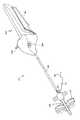
【図51】包装と出荷のための配置にあり、縫合糸カートリッジアセンブリが装填されていない時のこの発明の好ましい手術用器具の斜視図である。
【図52】図51の手術用器具の遠位部分の拡大斜視図である。
【図53】縫合糸カートリッジアセンブリを受けるための配置にある図51の手術用器具の斜視図である。
【図54】遠位部分に縫合糸カートリッジアセンブリが装填された時の配置にある図51の手術用器具の斜視図である。
【図55】内視鏡開口内に体内に導入される状態を示す図51の手術用器具の側面図である。
【図56】レバーが作動され、結び目が体組織に形成配置された後の図51の手術用器具の側面図である。
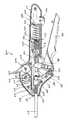
【図57】図51及び図54の両方に示した配置にある図51の手術用器具のハンドルアセンブリの内部側面図である。
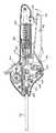
【図58】図53に示した装填/抜取配置にある図51の手術用器具のハンドルアセンブリの内部側面図である。
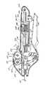
【図59】図55に示した配置にある図51の手術用器具のハンドルアセンブリの内部側面図である。
【図60】図56に示した配置にある図51の手術用器具のハンドルアセンブリの内部側面図である。[0001]
BACKGROUND OF THE INVENTION
The present invention relates to an assembly for facilitating the placement of surgical knots made of sutures. More particularly, the present invention relates to such an assembly that is particularly suitable for knot forming and placement during surgery with minimal intrusion such that access to the target site is limited.
[0002]
[Prior art]
As a main technique of the surgical operation, there is a technique in which a surgical knot made of a suture thread is formed during the operation, and the knot is placed in the body and the tissue is sutured. A number of surgical knots have been developed over time. The technique of forming a knot and sewing tissue is an important technique that a surgeon must acquire in order to perform surgery safely and efficiently. Therefore, such technology has been widely developed. For example, “Tissue Approximation in Endoscopic Surgery”, by Alfred Cuschieri and Zoltan Szabo, Times Mirror International Publishers (published in 1995), A number of surgical knots are described that consist of sutures to simplify the suturing.
[0003]
Many surgical knot techniques are also disclosed in the patent literature. U.S. Pat. No. 2,012,776 discloses a surgical instrument for simplifying the placement of various forms of slip knots made of sutures. H. A. Roeder, the inventor of this US Pat. No. 2,012,776, has developed a surgical knot called “Roeder Knot” which is still frequently used in surgery. More recently, US Pat. No. 5,573,286 discloses a surgical knot comprising a suture thread that is particularly useful in the field of orthopedics. In the preferred embodiment described in this US Pat. No. 5,573,286, a knot is applied to the bone.
[0004]
Traditionally, it has been considered difficult to form and place surgical knots within surgical sites accessible by remote control, which is cumbersome and often unreliable. To that end, instruments have been developed to simplify the knot placement by remote control. A preferred method is often to use a preformed knot loop of suture to reduce the number of steps required to form a tightly knotted knot. For example, U.S. Pat. Nos. 2,566,625 and 3,090,386 describe preformed knots made of sutures for suturing or tying tissue, particularly in the operation of difficult-to-access tissue. A surgical device suitable for supporting a loop is described.
[0005]
More recently, instruments have been developed that simplify the placement of knots during surgery, especially with minimal invasion. Specifically, in US Pat. No. 5,320,629, when an incised tissue is sutured in an endoscopic surgical operation, a knot loop made of a suture is formed in advance, and the knot loop is used as a surgical device. A method is disclosed that simplifies tightening of the knot loop by arranging. DE 912619 also discloses a device similar to that disclosed in US Pat. No. 5,320,629.
[0006]
[Problems to be solved by the invention]
Thus, surgical knot technology is well developed, and surgery to easily form tight knots from pre-formed knot loops of sutures for remote site surgery Equipment has also been developed, but there are still issues to be considered. Specifically, it is a knot that is formed and placed in a surgical operation with limited access to a target site, for example, during a minimally invasive procedure such as endoscopic surgery. Is always a slippery knot with poor safety. If the knot is not safe, the sutured tissue may not be retained for a period of time sufficient to heal the wound. In addition, during a surgical procedure with minimal invasion, the preformed knot loops of sutures described with respect to prior art devices are difficult to tighten efficiently for final knot formation. is there.
[0007]
Therefore, what is needed is an assembly to facilitate the formation of a surgical knot in a minimally invasive surgical procedure with limited access to a target site. This assembly should be relatively simple in construction and should be compatible with a partially tied (incomplete) surgical knot. This assembly also provides consistently strong knot safety each time the knot is placed, ensuring that even a less skilled surgeon can reliably and efficiently secure a suture knot from the suture. There is a need to facilitate the conversion from a partially tied (incomplete) knot to a fully knot so that it can be placed. In addition, in order to facilitate the use of this assembly for placement of surgical knots, the assembly can be easily adapted (retrofit) to various surgical instruments, particularly to endoscopic instruments. Would be desirable. In addition, if the assembly can be used to place a plurality of knots, the second partially tied knot can be reloaded into the assembly after forming and placing the first knot. Will be useful.
[0008]
Further, what is needed is a device that allows a suture cartridge assembly to be easily loaded into a surgical instrument. Specifically, what develops the current state of the surgical field is that a surgeon places a suture cartridge on a surgical instrument for forming and placing (ie, deploying) a surgical knot from a suture contained in a suture cartridge assembly. An apparatus for assisting in loading the assembly and for facilitating reloading of the second suture cartridge assembly after the depleted first suture cartridge assembly is removed from the surgical instrument. Will. Such a device is designed to eliminate the need for the user to handle the needle when the needle is attached to the suture and for shipping and storage of the suture cartridge when used with other packaging materials. It would be advantageous if it was designed to be a suitable container.
[0009]
Further, if a surgical instrument is provided that can easily form a complete knot by remote control (especially during endoscopic surgery where access to the body cavity is very limited), Would be desirable. In particular, remote control of internal tissue, sutures or needles (whatever is desired) to fully tie them from partially tied knots (ie, imperfect knots) It would be desirable to provide a surgical instrument having a handle assembly along with actuating means (actuators) to facilitate knot formation. More specifically, what is needed is a first actuating means for controlling remote manipulation of tissue, sutures or needles in the body for the formation of a perfect knot; A handle assembly having second actuating means for controlling and controlling remote operation.
[0010]
[Means for Solving the Problems]
The present invention relates to a surgical instrument for forming a knot in a completely tied state at the time of surgery to suture a body tissue. The surgical instrument includes a suture cartridge, a cartridge carrier, a gripping jaw, a handle assembly, and a closure tube.
[0011]
The surgical instrument suture cartridge is located at the distal end of the surgical instrument. The suture cartridge contains a suture having a partially tied knot formed at the distal end.
[0012]
The surgical instrument cartridge carrier is also located at the distal end of the surgical instrument. The cartridge carrier receives the suture cartridge.
[0013]
The grasping jaw of the surgical instrument faces the suture cartridge in the cartridge carrier. The gripping jaws are movable from an open position away from the suture cartridge to a closed position adjacent to the suture cartridge.
[0014]
The surgical instrument handle assembly is spaced from the suture cartridge. The handle assembly is located at the proximal end of the surgical instrument. The handle assembly has a grip for operating the surgical instrument. The handle assembly also has first actuating means for causing the gripping jaws to move from the open position to the closed position. In addition, the handle assembly also has second actuation means operatively connected to the proximal end of the suture. When the second actuating means is actuated, the proximal end of the suture is pulled in the proximal direction to form a fully tied knot from the partially tied knot to form body tissue. Is sutured.
[0015]
The closure tube of the surgical instrument connects the cartridge carrier to the handle assembly. The closure tube is movable from a proximal position to a distal position in response to actuation of the first actuation means. When the closure tube is in its proximal position, the gripping jaws of the surgical instrument are in its open position. Conversely, when the closure tube is in its distal position, the gripping jaw is in its closed position.
[0016]
It is important to note that the first and second actuation means of the surgical instrument handle assembly each allow the user to open and close a grasping jaw for grasping body tissue or suture. And allowing the sutures to be pulled functionally to form a fully knotted knot. The surgical instrument of the present invention can perform these two highly desirable functions, so that even if direct access to the subject's body structure is very constrained, it can be partially connected by an endoscope. This makes it easier to form and place a knot in a fully connected state from a knot in the connected state. The first actuating means moves the gripping jaws so that the body tissue or the suture can be appropriately operated for proper arrangement of the knot. Upon completion of this initial operation, the second actuating means is then activated to convert the partially tied knot into the desired fully tied knot for suturing the body tissue of interest. can do.
[0017]
The surgical instrument of the present invention can be used in any surgery where it is necessary or desirable to form a fully knotted knot and suture the body tissue. In a broad sense, the surgical instrument of the present invention can be used not only for endoscopic surgery but also for open surgery. However, the surgical instrument of the present invention is particularly suitable for endoscopic applications where direct access to the target tissue is very limited.
[0018]
DETAILED DESCRIPTION OF THE INVENTION
1-6 illustrate how a partially tied surgical knot can be formed from a length of suture. The imperfect surgical knot formed in this way can be used to implement the various embodiments of the invention described below. Of course, other incomplete surgical knots can also be used.
[0019]
The
[0020]
The length of
[0021]
As shown in FIG. 2, the
[0022]
Referring to FIG. 5, the loosely formed knot is tightened tightly by applying tension to the
[0023]
As shown in FIG. 6,
[0024]
To form the surgical knot, the knot tied in the incomplete state of FIG. 6 is formed and then tension is applied to the
[0025]
The incomplete knot illustrated in FIG. 6, sometimes referred to as a “blood” knot, is suitable for conversion to a non-slip surgical knot that is knotted into a complete state for use in the practice of this invention. However, other slip knots described in the aforementioned literature can also be used. A key characteristic for applying the present invention to a knot tied to another incomplete state is the formation of a common loop core (
[0026]
The perfect surgical knot is a
[0027]
FIGS. 9 and 10 show an example in which the partially tied knot shown in FIGS. 1 to 6 is formed around the
[0028]
A knot that is partially clamped around the
[0029]
When a partially tied knot is formed around the
[0030]
When the
[0031]
When the
[0032]
That is, advantageously, when tension is applied to the
[0033]
The
[0034]
In another example using this core tube concept, a partially tied knot is wrapped around the core tube to facilitate conversion to a fully non-slip knot for suturing tissue. To. This similar embodiment is shown in FIGS. One feature of this embodiment that differs from the embodiment illustrated in FIGS. 9-15 is that the core tube has a beveled distal end. For the sake of simplicity, in FIGS. 21 to 23, parts similar to those shown in FIGS. 9 to 15 are denoted by the same reference numerals.
[0035]
Another example of a knot in a partially tied state is shown in FIGS. The knot consists of a
[0036]
As particularly shown in FIG. 17, the
[0037]
The partially knotted knot shown in FIG. 17 is completed by applying axial tension proximally to the
[0038]
FIGS. 18 to 20 show examples in which the detachment tube (core tube) 73 is used to convert the partially knotted knot shown in FIG. 17 into a complete knot for suturing tissue. FIG. When the partially tied knot shown in FIG. 17 is formed, the
[0039]
The conversion from a partially tied knot to a fully knot is performed in a manner substantially similar to that previously described in connection with the knot transformation shown in FIG.
[0040]
As shown in FIGS. 19 and 20, the
[0041]
A preferred embodiment of a suture cartridge assembly that can be used in the practice of the present invention is shown in FIGS. This preferred embodiment is a further improvement of the assembly shown in FIGS. 11-15, comprising a partially tied knot wrapped around a core tube and subsequently loaded into a suture cartridge.
[0042]
Referring first to FIGS. 24 and 25, a
[0043]
The
[0044]
It is important that the gripping
[0045]
Referring now to FIGS. 28-32, details of the
[0046]
The
[0047]
Referring now to FIGS. 34 through 36, details of the gripping
[0048]
In a preferred embodiment, the suture cartridge assembly is a disposable assembly that is discarded after use by a single patient. The
[0049]
FIGS. 26 and 27 illustrate how the
[0050]
In a particularly preferred embodiment, a loaded suture cartridge assembly that can be used in the practice of the present invention is housed within the
[0051]
Reference is now made to FIGS. As can be seen, when the cartridge assembly is loaded into the
[0052]
FIGS. 40 to 49 show a loading assist device that can be used in cooperation with a preferred surgical instrument of the present invention, and a suture cartridge housed in the loading assist device. Shows how it is loaded.
[0053]
First, referring to FIGS. 40 to 42, details of the
[0054]
A cavity between the base 132 of the
[0055]
The
[0056]
The
[0057]
The
[0058]
The
[0059]
A suture cartridge suitable for practicing the present invention is an assembly as shown in FIGS. The
[0060]
The
[0061]
Referring now to FIGS. 43 through 49, there is shown a sequence of steps for loading the
[0062]
With particular reference to FIGS. 47 to 49, the
[0063]
A small gap (between the
[0064]
Once the
[0065]
50 to 60 show a
[0066]
FIGS. 51 to 56 show a sequence of expected operations of the
[0067]
FIG. 50 is an exploded perspective view of the components of the
[0068]
With further reference to FIG. 50 and now also referring to FIG. 57, the components of the
[0069]
With further reference to FIG. 57, the
[0070]
Referring now to FIG. 58, the
[0071]
When the spent or “fired”
[0072]
In FIG. 60, the
[0073]
With further reference to FIG. 60, it can be seen that the
[0074]
It will be appreciated that the handle assembly described above is of a preferred embodiment and that other grip shapes and in-assembly mechanisms are possible to achieve the intended function. For example, the handle assembly may have a “pistol grip” (pistol grip), or may have openings in the grip and trigger for insertion of the thumb and the opposing finger. In addition, the distal end portion of the surgical instrument can rotate about its longitudinal axis while the handle assembly remains stationary (a locking mechanism may be provided for this rotation). The surgical instrument described above may be disposable or reusable by the use of a single patient, depending on the material selection and assembly method, or a combination of the two.
[0075]
Although various embodiments of the present invention are representative embodiments of the present invention, these embodiments are merely examples. The scope of the present invention should not be construed as being limited by these embodiments or by any other specific embodiments that may occur to those skilled in the art, but should be construed according to the claims.
[0076]
The specific embodiments of the present invention are as follows.
(А) In a surgical instrument for suturing body tissue by forming a fully tied knot during surgery,
a) a suture cartridge at the distal end of the instrument containing a suture having a partially tied knot formed at the distal end;
b) a cartridge carrier at the distal end of the instrument for receiving the suture cartridge;
c) a gripping jaw facing the suture cartridge in the cartridge carrier that is movable from an open position away from the suture cartridge to a closed position adjacent to the suture cartridge;
d) i) a grip for operating the instrument,
ii) first actuating means for causing the gripping jaws to move from the open position to the closed position; and
iii) pulling the proximal end of the suture proximally so that a fully tied knot is formed from the partially tied knot and the body tissue is sutured; A handle assembly located at the proximal end of the instrument and spaced from the suture cartridge, having second actuation means operatively connected to the proximal end of the suture;
e) The cartridge carrier movable in response to actuation of the first actuating means from a proximal position where the gripping jaw is in its open position to a distal position in which the gripping jaw is in its closed position And a closure tube connecting the handle assembly to the handle assembly.
(1) The suture cartridge is loaded into the cartridge carrier when the closure tube is in its proximal position and when the closure tube is moved to an intermediate position between its proximal and distal positions. Fixed in the cartridge carrierEmbodiment (A)The instrument described in 1.
(2) The second actuating means and the suture proximal end to prevent the suture from breaking when the second actuating means is actuated to form a fully knotted knot. Further comprising a first biasing element capable of cooperating withEmbodiment (A)The instrument described in 1.
(3) a second capable of cooperating with the first actuating means to protect against overload when the second actuating means is actuated to move the closure tube from its proximal position to a distal position; The instrument of embodiment (2), further comprising a biasing element.
(4) the first actuating means is a trigger pivotally attached to the handle assembly, and is movable from a first trigger position away from the grip to a second trigger position adjacent to the grip; The closure tube is in its proximal position when the first actuating means is in its first trigger position and is in its distal position when the second actuating means is in its second trigger positionEmbodiment (A)The instrument described in 1.
(5) The first actuating means is movable to a third trigger position between the first trigger position and the second trigger position, and the closure tube is located when the first actuating means is at the third trigger position. The device according to embodiment (4), wherein is in its intermediate position.
[0077]
(6) The second actuating means is a lever pivotally attached to the handle assembly, and the lever is a first lever so as to form a knot in a fully tied state by pulling the suture end. The instrument of embodiment (4), wherein the instrument is pivoted from a position to a second lever position.
(7) The instrument according to embodiment (6), wherein the handle assembly of the instrument is suitable for one-handed operation to actuate the trigger and the lever when the grip is placed in the palm of a user.
(8) Embodiment in which the trigger is biased toward the first trigger position, the closure tube is biased toward the proximal position, and the lever is biased toward the first lever position. The instrument as described in (7).
(9) further comprising a release button protruding from the handle assembly, the release button being operable with the closure tube and the trigger, wherein the release button is pushed inward toward the handle assembly and the trigger is The instrument of embodiment (8), wherein when in the second or third trigger position, the trigger moves to the first trigger position.
(10) The suture cartridge has a hook slot therein, a proximal end of the suture traverses the hook slot, and the lever is connected to a pinion provided in the handle assembly. The instrument as described in (6).
[0078]
(11) A rack provided in the handle assembly and capable of cooperating with the pinion, and a suture pulling rod connected to the rack are further provided, and the suture pulling rod is connected to the cartridge carrier from the handle assembly. The suture pulling rod has a hook extending at a distal end thereof through the hook slot of the suture cartridge, and the pinion has the lever from the first lever position to the second lever. Moving the rack and a suture pull rod connected to the rack in a proximal direction when pivoted to a position, wherein the hook of the suture pull rod is fully tied from the partially tied knot Before traversing the hook slot in the suture cartridge to form a knot Instrument of Claim pulling the proximal end of the suture in a proximal direction (10).
[0079]
【The invention's effect】
As described above, according to the suture cartridge assembly of the present invention, the user opens or closes the grasping jaws by the first operating means of the handle assembly of the surgical instrument, and the body tissue or the suture thread. And the second actuating means can pull the suture functionally to form a fully tied knot from a partially tied knot. Even when direct access to the anatomy of the surgical object is very limited, the endoscope can form and place a fully tied knot from a partially tied knot Can be done easily.
The surgical instrument of the present invention can be used in any surgical procedure where it is necessary or desirable to form a fully-knotted knot and suture the body tissue. It is particularly suitable for endoscopic surgery where direct access to the is very limited.
[Brief description of the drawings]
FIG. 1 is a perspective view illustrating a series of steps for forming a knot in a partially tied state from a length of suture.
FIG. 2 is a perspective view illustrating a series of steps for forming a knot in a partially tied state from a certain length of suture.
FIG. 3 is a perspective view illustrating a series of steps for forming a knot in a partially tied state from a certain length of suture.
FIG. 4 is a perspective view illustrating a series of steps for forming a knot in a partially tied state from a length of suture.
FIG. 5 is a perspective view illustrating a series of steps for forming a knot in a state of being partially tied from a certain length of suture.
FIG. 6 is a perspective view illustrating a series of steps for forming a knot in a state of being partially tied from a certain length of suture.
7 is a perspective view of the process of converting the partially tied knot shown in FIG. 6 to a non-slip surgical knot.
8 is a perspective view of the process of converting the partially tied knot shown in FIG. 6 into a non-slip surgical knot.
9 is a perspective view showing an example in which the partially tied knot shown in FIG. 6 including a surgical needle attached to a suture is formed around a core tube. FIG.
10 is a perspective view showing an example in which the partially tied knot shown in FIG. 6 including a surgical needle attached to a suture is formed around a core tube. FIG.
11 is an exploded perspective view illustrating a suture cartridge with the partially tied knot shown in FIG. 6 formed around the core tube shown in FIGS. 9 and 10. FIG.
12 is a perspective view showing an assembly of the suture cartridge shown in FIG. 11 with a cartridge top plate attached thereto. FIG.
13 is a cross-sectional view of the assembly taken along line 13-13 of FIG.
FIG. 14 includes a partial cross-section of tissue showing the process of forming a complete surgical knot to securely suture the tissue from a partially tied knot for suturing the tissue. It is sectional drawing of the assembly shown in FIG.
FIG. 15 includes a partial cross-section of tissue showing the process of forming a full surgical knot to securely suture the tissue from a partially tied knot for suturing the tissue. It is sectional drawing of the assembly shown in FIG.
FIG. 16 is a perspective view showing the formation of another partially tied knot from a length of suture.
FIG. 17 is a perspective view showing the formation of another partially tied knot from a length of suture.
18 is a perspective view of the knot in the partially tied state shown in FIG. 17 formed around the desorption tube.
FIG. 19 is a side view illustrating an example of forming a complete non-slip surgical knot for suturing tissue using the assembly shown in FIG. 18;
20 is a side view illustrating an example of forming a complete non-slip surgical knot for suturing tissue using the assembly shown in FIG. 18. FIG.
21 illustrates an example of forming a complete non-slip surgical knot for suturing tissue from the partially tied knot shown in FIG. 6 formed around a tilted core tube. FIG.
22 illustrates an example of forming a complete non-slip surgical knot for suturing tissue from the partially tied knot shown in FIG. 6 formed around a tilted core tube. FIG.
FIG. 23 illustrates an example of forming a complete non-slip surgical knot for suturing tissue from the partially tied knot shown in FIG. 6 formed around a tilted core tube. FIG.
FIG. 24 is a perspective view of a preferred suture cartridge assembly.
FIG. 25 is an exploded perspective view showing the partially tied knot of the preferred suture cartridge assembly, wrapped around the core tube and separated from the suture cartridge assembly.
26 is an exploded perspective view showing the initial steps of assembling the suture cartridge assembly of FIGS. 24 and 25, with a surgical needle attached to the distal end of the suture being loaded into the cartridge slot of the suture cartridge. FIG. is there.
FIG. 27 is a perspective view showing the next step following loading of the core tube into the cartridge slot, where the proximal end of the suture is secured to the cartridge housing attached to the suture cartridge.
FIG. 28 is a plan view of the preferred suture cartridge assembly of FIG. 24 having a cartridge housing.
29 is a left side view of the cartridge of FIG. 28. FIG.
30 is a bottom view of the cartridge of FIG. 28. FIG.
31 is a right side view of the cartridge of FIG. 28. FIG.
32 is a rear or proximal end view of the cartridge of FIG. 28. FIG.
33 is an exploded perspective view showing the arrangement of the suture cartridge after loading in FIG. 24 on the cartridge carrier.
34 is a bottom view of the gripping jaws of the suture cartridge assembly of FIG. 24. FIG.
35 is a right side view of the gripping jaw of FIG. 34. FIG.
36 is a proximal end view of the gripping jaw of FIG. 35. FIG.
FIG. 37 is a perspective view of the suture cartridge assembly of FIG. 24 attached to a cartridge carrier and used in conjunction with a surgical instrument closure tube to grasp tissue.
FIG. 38 is a perspective view similar to FIG. 37 using a suture cartridge assembly to grip a portion of the suture.
FIG. 39 is a perspective view similar to the view of FIG. 37 using a suture cartridge assembly to grasp a surgical needle.
FIG. 40 is a perspective view of a preferred loading assist device in cooperation with a suture cartridge of a preferred surgical instrument of the present invention.
41 is a proximal end view of the loading assist device of FIG. 40. FIG.
42 is an exploded view of the loading assist device of FIG. 40 showing the containment of the suture cartridge within the cartridge case.
FIG. 43 is an internal side view of the cartridge case base showing the arrangement of the suture cartridge with the suture and surgical needle within the cartridge case base. The cartridge case upper cover for the loading assist device is indicated by a virtual line. The preferred surgical instrument cartridge carrier of the present invention is shown in a pre-loading relationship with a loading aid.
44 is an internal side view of the loading assist device of FIG. 40 when the cartridge carrier of the preferred surgical instrument of the present invention contacts the suture cartridge within the cartridge case. FIG.
45 is an internal side view of the loading assist device of FIG. 40 showing the suture cartridge seated on the cartridge carrier of the preferred surgical instrument of the present invention. FIG.
46 shows the interior of the loading assist device of FIG. 40 showing the suture cartridge assembly secured to the cartridge carrier when the closure tube of the preferred surgical instrument of the present invention moves forward to cover a portion of the suture cartridge. It is a side view.
47 is an internal side view of the loading assist device of FIG. 40 showing a partial retraction of the cartridge carrier after loading.
48 is an internal side view of the loading assist device of FIG. 40 showing further retraction of the cartridge carrier after loading.
49 is an internal side view of the loading assist device of FIG. 40 showing separation of the cartridge carrier after loading.
FIG. 50 is an exploded perspective view of the components of the handle assembly for the preferred surgical instrument of the present invention.
FIG. 51 is a perspective view of a preferred surgical instrument of the present invention when in a packaging and shipping configuration and not loaded with a suture cartridge assembly.
52 is an enlarged perspective view of a distal portion of the surgical instrument of FIG. 51. FIG.
53 is a perspective view of the surgical instrument of FIG. 51 in an arrangement for receiving a suture cartridge assembly. FIG.
54 is a perspective view of the surgical instrument of FIG. 51 in an arrangement when the distal portion is loaded with a suture cartridge assembly. FIG.
55 is a side view of the surgical instrument of FIG. 51 showing a state of being introduced into the body into the endoscope opening.
56 is a side view of the surgical instrument of FIG. 51 after the lever has been actuated and the knot has been formed and placed in body tissue.
57 is an internal side view of the handle assembly of the surgical instrument of FIG. 51 in the arrangement shown in both FIGS. 51 and 54. FIG.
58 is an internal side view of the handle assembly of the surgical instrument of FIG. 51 in the loading / withdrawing arrangement shown in FIG. 53. FIG.
59 is an internal side view of the handle assembly of the surgical instrument of FIG. 51 in the arrangement shown in FIG. 55. FIG.
60 is an internal side view of the handle assembly of the surgical instrument of FIG. 51 in the arrangement shown in FIG. 56. FIG.
Claims (10)
Translated fromJapanesea)前記器具(121)の遠位端に配置される縫合糸カートリッジ(80)であって、
前記縫合糸カートリッジ(80)は、縫合糸(81)を収容しており、
前記縫合糸(81)は、前記縫合糸(81)の遠位端(83)に、部分的に結ばれた状態の結び目が形成されている、
縫合糸カートリッジと、
b)前記縫合糸カートリッジ(80)を収容するための、前記器具(121)の遠位端に設けられたカートリッジキャリア(120)と、
c)前記縫合糸カートリッジ(80)に取り付けられている把持用ジョー(94)であって、
前記把持用ジョー(94)は、前記カートリッジキャリア(120)に収容される前記縫合糸カートリッジ(80)の上面に対向しており、かつ、
前記縫合糸カートリッジ(80)から離れた開放位置から前記縫合糸カートリッジ(80)に隣接する閉鎖位置まで移動可能である、
把持用ジョーと、
d)前記縫合糸カートリッジ(80)から離されて前記器具(121)の近位端に配置されたハンドルアセンブリ(300)であって、
前記ハンドルアセンブリ(300)は、
i)前記器具(121)を操作するためのグリップ(192)、
ii)前記把持用ジョー(94)を前記開放位置から前記閉鎖位置まで移動させるための第1作動手段(180)、および、
iii)前記縫合糸(81)の近位端(82)に作用可能に接続された第2作動手段(220)であって、
前記第2作動手段(220)は、前記縫合糸の前記近位端(82)を近位側に引っ張ることができ、
前記縫合糸の前記近位端を近位側に引っ張って、体の組織を縫合するように前記部分的に結ばれた状態の結び目から、完全に結ばれた状態の結び目を形成する、
第2作動手段、
を有する、ハンドルアセンブリと、
e)前記カートリッジキャリア(120)を前記ハンドルアセンブリ(300)に連結するクロージャー管(126)であって、
前記クロージャー管(126)は、前記第1作動手段(180)の作動に応答して、近位位置から遠位位置へ移動可能であり、
前記クロージャー管(126)が、前記近位位置にあると前記把持用ジョー(94)は、前記開放位置にあり、
前記クロージャー管(126)が、前記遠位位置にあると、前記把持用ジョー(94)は、前記閉鎖位置にある、
クロージャー管と、
を備えた、手術用器具。In a surgical instrument(121) for suturing body tissue by forming a fully tied knot during surgery,
a)a suture cartridge (80) disposed at a distal end of the instrument (121), comprising:
The suture cartridge (80) contains a suture (81),
The suture (81) has a knot in a partially tied stateat the distal end (83) of the suture (81).
A suture cartridge;
b) the orderto accommodatethe suture cartridge(80), andsaid cartridge carrierat the distal end of the instrument(121)(120),
c)a gripping jaw (94) attached to the suture cartridge (80),
The gripping jaw (94) faces the upper surface of the suture cartridge (80) housed in the cartridge carrier (120), and
It is movable from an open position away fromsaid suture cartridge(80) to a closed position adjacentsaid suture cartridge(80),
A gripping jaw;
d) a handle assembly (300) positioned at the proximal end of the instrument (121) away from the suture cartridge (80),
The handle assembly (300)
i) a grip for operatingthe instrument(121)(192),
ii) a first actuating means formovingthe gripping jaws(94) tosaid closed position fromthe open position(180),and,
iii)second actuating means (220) operatively connected to the proximal end (82) of the suture (81),
The second actuation means (220) can pull the proximal end (82) of the suture proximally;
Pulling the proximal end of the suture proximallyto forma fully tied knot fromthe partially tied knot tosuture body tissue ;
Second actuating means,
A handle assembly,
e)a closure tube (126) connecting the cartridge carrier (120) to the handle assembly (300),
The closure tube (126) ismovable from aproximal position to a distal position in response to actuation of the first actuation means(180);
When the closure tube (126) is in the proximal position, the gripping jaw(94) is in the open position;
When the closure tube (126) is in the distal position, the gripping jaw(94) is inthe closed position;
A closure tube,
With asurgical instrument.
前記縫合糸カートリッジ(80)は、前記クロージャー管(126)が前記近位位置にあるときに前記カートリッジキャリア(120)に収容されることができ、 The suture cartridge (80) can be received in the cartridge carrier (120) when the closure tube (126) is in the proximal position;
前記クロージャー管(126)が、前記近位位置と前記遠位位置との間の中間位置に移動されたとき、前記縫合糸カートリッジ(80)は、前記カートリッジキャリア(120)内に固定される、手術用器具。 When the closure tube (126) is moved to an intermediate position between the proximal and distal positions, the suture cartridge (80) is secured within the cartridge carrier (120); Surgical instruments.
前記第2作動手段(220)が前記完全に結ばれた状態の結び目を形成するように作動されたときに、前記第1付勢要素(250)は、前記縫合糸(81)が破断されるのを防ぐために、 When the second actuating means (220) is actuated to form the fully tied knot, the first biasing element (250) breaks the suture (81). To prevent
第2作動手段(220)および前記縫合糸(81)の前記近位端(82)と協働可能な第1付勢要素(250)、 A first biasing element (250) cooperating with a second actuation means (220) and the proximal end (82) of the suture (81);
をさらに備える、 Further comprising
手術用器具。 Surgical instruments.
前記第1作動手段(180)が作動されて前記クロージャー管(126)が、前記近位位置から前記遠位位置まで移動するときに、前記第2付勢要素(242)は、過剰な力に対する保護を与えるために、 When the first actuating means (180) is actuated to move the closure tube (126) from the proximal position to the distal position, the second biasing element (242) To give protection
前記第1作動手段(180)と協働可能な第2付勢要素(242)、 A second biasing element (242) capable of cooperating with the first actuating means (180);
をさらに備える、 Further comprising
手術用器具。 Surgical instruments.
前記第1作動手段(180)は、前記ハンドルアセンブリ(300)に旋回可能に取り付けられたトリガー(180)であり、 The first actuating means (180) is a trigger (180) pivotably attached to the handle assembly (300);
前記第1作動手段(180)は、前記グリップ(192)から離れている第1トリガー位置から、前記グリップ(192)に近接している第2トリガー位置まで移動可能であり、 The first actuating means (180) is movable from a first trigger position remote from the grip (192) to a second trigger position close to the grip (192);
前記第1作動手段(180)が前記第1トリガー位置に位置するとき、前記クロージャー管(126)は、前記近位位置にあり、 When the first actuating means (180) is in the first trigger position, the closure tube (126) is in the proximal position;
前記第 Said11作動手段(180)が前記第2トリガー位置に位置するとき、前記クロージャー管(126)は、前記遠位位置にある、When the actuation means (180) is located in the second trigger position, the closure tube (126) is in the distal position;
手術用器具。 Surgical instruments.
前記第1作動手段(180)は、前記第1トリガー位置と前記第2トリガー位置との間にある第3トリガー位置に移動可能であり、 The first actuating means (180) is movable to a third trigger position between the first trigger position and the second trigger position;
前記第1作動手段(180)が前記第3トリガー位置に位置するとき、前記クロージャー管(126)は、前記近位位置と前記遠位位置の中間位置にある、 When the first actuating means (180) is located in the third trigger position, the closure tube (126) is in an intermediate position between the proximal position and the distal position;
手術用器具。 Surgical instruments.
前記第2作動手段(220)は、前記ハンドルアセンブリ(300)に旋回可能に取り付けられたレバー(220)であり、 The second actuating means (220) is a lever (220) pivotably attached to the handle assembly (300);
前記レバー(220)は、前記完全に結ばれた状態の結び目を形成するために前記縫合糸(81)の近位端を近位側に引っ張るように、第1レバー位置から第2レバー位置まで旋回される、 From the first lever position to the second lever position, the lever (220) pulls the proximal end of the suture (81) proximally to form the fully tied knot. Swirled,
手術用器具。 Surgical instruments.
前記グリップ(192)が使用者の手のひらに置かれたときに、前記トリガー(180)および前記レバー(220)を作動させるために片手で操作できるように、前記手術用器具の前記ハンドルアセンブリ(300)が構成されている、 When the grip (192) is placed on the palm of a user, the handle assembly (300 of the surgical instrument) can be operated with one hand to actuate the trigger (180) and the lever (220). ) Is configured,
手術用器具。 Surgical instruments.
前記トリガー(180)は、前記第 The trigger (180) is the first11トリガー位置に付勢され、Biased to the trigger position,
前記クロージャー管(126)は、前記近位位置に付勢され、 The closure tube (126) is biased to the proximal position;
前記レバー(220)は、前記第 The lever (220)11レバー位置に付勢されている、Biased to the lever position,
手術用器具。 Surgical instruments.
前記ハンドルアセンブリ(300)から突出した解放ボタン(238、240)、 Release buttons (238, 240) protruding from the handle assembly (300);
をさらに備え、 Further comprising
前記解放ボタン(238、240)は、前記クロージャー管(126)および前記トリガー(180)と協働可能であり、 The release buttons (238, 240) can cooperate with the closure tube (126) and the trigger (180);
前記トリガー(180)が前記第2トリガー位置または前記第3トリガー位置にあるときに、前記解放ボタン(238、240)が、前記ハンドルアセンブリ(300)に向かって内側に押さげられると、前記トリガー(180)は、前記第1トリガー位置に移動する、 When the trigger (180) is in the second trigger position or the third trigger position and the release button (238, 240) is pushed inward toward the handle assembly (300), the trigger (180) moves to the first trigger position;
手術用器具。 Surgical instruments.
Priority Applications (1)
| Application Number | Priority Date | Filing Date | Title |
|---|---|---|---|
| JP30330698AJP4137249B2 (en) | 1998-10-10 | 1998-10-10 | Surgical instrument for forming a knot |
Applications Claiming Priority (1)
| Application Number | Priority Date | Filing Date | Title |
|---|---|---|---|
| JP30330698AJP4137249B2 (en) | 1998-10-10 | 1998-10-10 | Surgical instrument for forming a knot |
Publications (2)
| Publication Number | Publication Date |
|---|---|
| JP2000116659A JP2000116659A (en) | 2000-04-25 |
| JP4137249B2true JP4137249B2 (en) | 2008-08-20 |
Family
ID=17919380
Family Applications (1)
| Application Number | Title | Priority Date | Filing Date |
|---|---|---|---|
| JP30330698AExpired - LifetimeJP4137249B2 (en) | 1998-10-10 | 1998-10-10 | Surgical instrument for forming a knot |
Country Status (1)
| Country | Link |
|---|---|
| JP (1) | JP4137249B2 (en) |
Cited By (2)
| Publication number | Priority date | Publication date | Assignee | Title |
|---|---|---|---|---|
| KR101132070B1 (en)* | 2010-02-05 | 2012-04-02 | 국립암센터 | Surgery apparatus for suturing |
| KR20200053044A (en)* | 2018-11-07 | 2020-05-18 | 유펙스메드 주식회사 | A medical discharging device with multiple tips |
Families Citing this family (4)
| Publication number | Priority date | Publication date | Assignee | Title |
|---|---|---|---|---|
| JP4500204B2 (en)* | 2005-04-28 | 2010-07-14 | オリンパスメディカルシステムズ株式会社 | Thread winding fixing method for coated tube for bending part |
| JP2008020110A (en)* | 2006-07-12 | 2008-01-31 | Mitsubishi Electric Corp | Showcase water level sensor |
| EP2967550A4 (en) | 2013-03-15 | 2016-11-09 | Anchor Orthopedics Xt Inc | APPARATUS AND METHODS FOR CHARGING SUTURE |
| US10004490B2 (en)* | 2014-06-06 | 2018-06-26 | Ethicon Llc | Force limited needle driver |
Family Cites Families (1)
| Publication number | Priority date | Publication date | Assignee | Title |
|---|---|---|---|---|
| JP3798838B2 (en)* | 1995-01-20 | 2006-07-19 | オリンパス株式会社 | Ligation device |
- 1998
- 1998-10-10JPJP30330698Apatent/JP4137249B2/ennot_activeExpired - Lifetime
Cited By (3)
| Publication number | Priority date | Publication date | Assignee | Title |
|---|---|---|---|---|
| KR101132070B1 (en)* | 2010-02-05 | 2012-04-02 | 국립암센터 | Surgery apparatus for suturing |
| KR20200053044A (en)* | 2018-11-07 | 2020-05-18 | 유펙스메드 주식회사 | A medical discharging device with multiple tips |
| KR102161618B1 (en) | 2018-11-07 | 2020-10-06 | 유펙스메드 주식회사 | A medical discharging device with multiple tips |
Also Published As
| Publication number | Publication date |
|---|---|
| JP2000116659A (en) | 2000-04-25 |
Similar Documents
| Publication | Publication Date | Title |
|---|---|---|
| US5846254A (en) | Surgical instrument for forming a knot | |
| US5897564A (en) | Endoscopic instrument assembly for fastening tissue | |
| US5814069A (en) | Load assist device for a suture cartridge | |
| JP4008106B2 (en) | Suture cartridge assembly for surgical knots | |
| CA2141912C (en) | Surgical suture instrument | |
| JP3977512B2 (en) | Partially tied surgical knot and its assembly | |
| JP3902308B2 (en) | Surgical knot and its forming device | |
| CA2141913C (en) | Method and apparatus for applying a cinch member to the ends of suture loop | |
| CA2141911C (en) | Surgical crimping device and method of use | |
| US5474568A (en) | Instrument for closing trocar puncture wounds | |
| JP3604701B2 (en) | Ligation forming device | |
| CA2173520C (en) | Surgical suturing apparatus | |
| US5181919A (en) | Suture ligating device for use with an endoscope | |
| JP5763531B2 (en) | Endoscopic suture system | |
| US5300078A (en) | Device and method for applying large-diameter ligating loop | |
| EP0504312B1 (en) | Suture tie device system and applicator therefor | |
| JPH05503442A (en) | Endoscopic stapling device and method | |
| JP2009106757A (en) | Disposable cartridge for use in gastric volume reduction procedure | |
| JPH11511373A (en) | Ligation device with multiple loop ligature supply and method | |
| JP2009106756A (en) | Method for deploying device for gastric volume reduction | |
| JP2003225241A (en) | Therapeutic manipulator for endoscope | |
| NL2019974B1 (en) | Suture device | |
| JP4137249B2 (en) | Surgical instrument for forming a knot | |
| JPH09313493A (en) | Connecting method and connecting device for operation suture |
Legal Events
| Date | Code | Title | Description |
|---|---|---|---|
| A621 | Written request for application examination | Free format text:JAPANESE INTERMEDIATE CODE: A621 Effective date:20051007 | |
| A131 | Notification of reasons for refusal | Free format text:JAPANESE INTERMEDIATE CODE: A131 Effective date:20071002 | |
| RD04 | Notification of resignation of power of attorney | Free format text:JAPANESE INTERMEDIATE CODE: A7424 Effective date:20071120 | |
| A601 | Written request for extension of time | Free format text:JAPANESE INTERMEDIATE CODE: A601 Effective date:20071227 | |
| A602 | Written permission of extension of time | Free format text:JAPANESE INTERMEDIATE CODE: A602 Effective date:20080107 | |
| A521 | Written amendment | Free format text:JAPANESE INTERMEDIATE CODE: A523 Effective date:20080401 | |
| TRDD | Decision of grant or rejection written | ||
| A01 | Written decision to grant a patent or to grant a registration (utility model) | Free format text:JAPANESE INTERMEDIATE CODE: A01 Effective date:20080507 | |
| A01 | Written decision to grant a patent or to grant a registration (utility model) | Free format text:JAPANESE INTERMEDIATE CODE: A01 | |
| A61 | First payment of annual fees (during grant procedure) | Free format text:JAPANESE INTERMEDIATE CODE: A61 Effective date:20080604 | |
| R150 | Certificate of patent or registration of utility model | Free format text:JAPANESE INTERMEDIATE CODE: R150 | |
| FPAY | Renewal fee payment (event date is renewal date of database) | Free format text:PAYMENT UNTIL: 20110613 Year of fee payment:3 | |
| FPAY | Renewal fee payment (event date is renewal date of database) | Free format text:PAYMENT UNTIL: 20110613 Year of fee payment:3 | |
| FPAY | Renewal fee payment (event date is renewal date of database) | Free format text:PAYMENT UNTIL: 20120613 Year of fee payment:4 | |
| FPAY | Renewal fee payment (event date is renewal date of database) | Free format text:PAYMENT UNTIL: 20120613 Year of fee payment:4 | |
| FPAY | Renewal fee payment (event date is renewal date of database) | Free format text:PAYMENT UNTIL: 20130613 Year of fee payment:5 | |
| R250 | Receipt of annual fees | Free format text:JAPANESE INTERMEDIATE CODE: R250 | |
| R250 | Receipt of annual fees | Free format text:JAPANESE INTERMEDIATE CODE: R250 | |
| R250 | Receipt of annual fees | Free format text:JAPANESE INTERMEDIATE CODE: R250 | |
| R250 | Receipt of annual fees | Free format text:JAPANESE INTERMEDIATE CODE: R250 | |
| R250 | Receipt of annual fees | Free format text:JAPANESE INTERMEDIATE CODE: R250 | |
| EXPY | Cancellation because of completion of term |