JP4136187B2 - Sample transfer device - Google Patents
Sample transfer deviceDownload PDFInfo
- Publication number
- JP4136187B2 JP4136187B2JP13494299AJP13494299AJP4136187B2JP 4136187 B2JP4136187 B2JP 4136187B2JP 13494299 AJP13494299 AJP 13494299AJP 13494299 AJP13494299 AJP 13494299AJP 4136187 B2JP4136187 B2JP 4136187B2
- Authority
- JP
- Japan
- Prior art keywords
- sample
- rack
- unit
- specimen
- storage rack
- Prior art date
- Legal status (The legal status is an assumption and is not a legal conclusion. Google has not performed a legal analysis and makes no representation as to the accuracy of the status listed.)
- Expired - Lifetime
Links
- 238000012546transferMethods0.000titleclaimsdescription41
- 239000000523sampleSubstances0.000claimsdescription232
- 230000032258transportEffects0.000claimsdescription25
- 238000012360testing methodMethods0.000claimsdescription8
- 239000000550preparative sampleSubstances0.000claimsdescription2
- 239000012491analyteSubstances0.000claims1
- 239000008280bloodSubstances0.000description60
- 210000004369bloodAnatomy0.000description60
- 230000007246mechanismEffects0.000description12
- 238000005259measurementMethods0.000description10
- 238000010586diagramMethods0.000description4
- 210000002700urineAnatomy0.000description3
- 239000012472biological sampleSubstances0.000description2
- 230000000694effectsEffects0.000description2
- 238000009434installationMethods0.000description2
- 238000012545processingMethods0.000description2
- 230000009471actionEffects0.000description1
- 238000010876biochemical testMethods0.000description1
- 238000009534blood testMethods0.000description1
- 210000004204blood vesselAnatomy0.000description1
- 230000008859changeEffects0.000description1
- 239000003814drugSubstances0.000description1
- 238000012812general testMethods0.000description1
- 238000000034methodMethods0.000description1
- 230000008569processEffects0.000description1
- 230000008707rearrangementEffects0.000description1
- 238000005070samplingMethods0.000description1
Images


Classifications
- G—PHYSICS
- G01—MEASURING; TESTING
- G01N—INVESTIGATING OR ANALYSING MATERIALS BY DETERMINING THEIR CHEMICAL OR PHYSICAL PROPERTIES
- G01N35/00—Automatic analysis not limited to methods or materials provided for in any single one of groups G01N1/00 - G01N33/00; Handling materials therefor
- G01N35/02—Automatic analysis not limited to methods or materials provided for in any single one of groups G01N1/00 - G01N33/00; Handling materials therefor using a plurality of sample containers moved by a conveyor system past one or more treatment or analysis stations
- G01N35/04—Details of the conveyor system
- G01N2035/0401—Sample carriers, cuvettes or reaction vessels
- G01N2035/0406—Individual bottles or tubes
- G—PHYSICS
- G01—MEASURING; TESTING
- G01N—INVESTIGATING OR ANALYSING MATERIALS BY DETERMINING THEIR CHEMICAL OR PHYSICAL PROPERTIES
- G01N35/00—Automatic analysis not limited to methods or materials provided for in any single one of groups G01N1/00 - G01N33/00; Handling materials therefor
- G01N35/02—Automatic analysis not limited to methods or materials provided for in any single one of groups G01N1/00 - G01N33/00; Handling materials therefor using a plurality of sample containers moved by a conveyor system past one or more treatment or analysis stations
- G01N35/04—Details of the conveyor system
- G01N2035/0496—Other details
- G01N2035/0498—Drawers used as storage or dispensing means for vessels or cuvettes
- G—PHYSICS
- G01—MEASURING; TESTING
- G01N—INVESTIGATING OR ANALYSING MATERIALS BY DETERMINING THEIR CHEMICAL OR PHYSICAL PROPERTIES
- G01N35/00—Automatic analysis not limited to methods or materials provided for in any single one of groups G01N1/00 - G01N33/00; Handling materials therefor
- G01N35/0099—Automatic analysis not limited to methods or materials provided for in any single one of groups G01N1/00 - G01N33/00; Handling materials therefor comprising robots or similar manipulators
Landscapes
- Physics & Mathematics (AREA)
- Health & Medical Sciences (AREA)
- Life Sciences & Earth Sciences (AREA)
- Chemical & Material Sciences (AREA)
- Analytical Chemistry (AREA)
- Biochemistry (AREA)
- General Health & Medical Sciences (AREA)
- General Physics & Mathematics (AREA)
- Immunology (AREA)
- Pathology (AREA)
- Automatic Analysis And Handling Materials Therefor (AREA)
Description
Translated fromJapanese【0001】
【産業上の利用分野】
本発明は、臨床検査で用いられる血液や尿等の検体を検体ラックから取出し、収納ラックに所定の順序で収める検体移し替え装置に関する、特に分析装置等間に検体ラックを搬送させる搬送ユニットに接続するのに好適である。
【0002】
【発明が解決しようとする課題】
病院や検査センターにおける臨床検査では、血液や尿等の生体試料を検体として、血液検査、生化学検査、一般検査などの種々の検査が行われている。これらの検査の分析装置は、検体を検体ラックに収めてセットすれば自動的に測定してゆくサンプラを備えるものが一般的である。さらに近年では、複数の分析装置間に検体を自動的に移送してゆく搬送システムも効率化のために用いられるようになっている(参照:特開昭63−217273、特開平3−94159)。
【0003】
このようにして検査された検体は、その検査結果や他の検査結果等によっては、再検査等に用いなければならない場合もある。そのため検査に用いた検体は所定期間保管しておくようにされている。その際、検査されたままの状態で検体ラックごと保管しておくと手間はかからないが、検体ラックは通常10検体用または5検体用の細長いラックであり、ラックが倒れたりしないよう順番どおり立てれる置き場を準備しなくてはならない。検査は通常、検体を受付順に測定してゆき、その途中で緊急検体を割り込ませたり、特定検体を取出したりするので、測定終了順に並べておいても、目的とする検体を探し出すのは大変で、検体の多い施設では緊急検査等の対応が困難である。
【0004】
そこで、測定が終わった検体の選び出しがすぐにできるように、診療科目別や外来入院別などに仕分けたり、検体ID順など適当な順序に並び換えるようにすることが望まれている。しかし、この作業を手作業で行うことは検体の多い施設では大変な作業であり、現実には余り運用されてはいない。
【0005】
この作業の自動化として、従来の検体搬送ユニットを工夫して、測定された検体ラックを所定の順序に並び換えるユニットを分析装置の後に入れることが考えられるが、検体ラック単位で並び換えても、検体が検体ラックに順序どおり並べていなければ効果が低い。
本発明の目的は、検体ラックに検体をセットして測定する順序に何ら制限なく、測定した検体を所定の順序で検体収納ラックに自動的に移し替えることを目的とする。
【0006】
【課題を解決するための手段】
本発明は上記の目的を達成するためになされたもので、分析装置に供された後の検体を収納した検体ラックを移送させる輸送ユニットと、輸送ユニットによって移送される検体ラック内の検体の検体IDを読み取る検体ID読み取り部と、検体を収納する検体収納ラックを複数架設できる検体収納ラックテーブルと、検体ID読み取り部により検体IDが読取られた検体を検体ラックから取出し、取出した検体を検体収納ラックに収める検体移し替え手段と、検体移し替え手段が取出した検体を、検体収納ラックに収める順序を制御するコントロールユニットを備えた検体移し替え装置を提供するものである。また、本発明は、分析装置に供された後の検体を収納した検体ラックを移送させる輸送ユニットと、輸送ユニットによって移送される検体ラック内の検体の検体IDを読み取る検体ID読み取り部と、検体を収納する検体収納ラックを複数架設できる検体収納ラックテーブルと、検体ID読み取り部により検体IDが読取られた検体を検体ラックから取出し、取出した検体を検体収納ラックに収める検体移し替え手段と、検体移し替え手段が取出した検体を、何れの検体収納ラックに収めるかを制御するコントロールユニットとを備えた検体移し替え装置を提供するものである。
【0007】
【発明の実施の形態】
この発明における検体移し替え装置に用いられる検体とは、血液や尿などの生体試料が採血管やスピッツなどの容器に収納されたものをいう。検体ラックはその検体が収められるラックで分析装置のサンプラにあわせたものが用いられる。そして、移し替えられる検体収納ラックとは、検体を保管するためのラックで、保管に便利なように50検体や100検体とか多数の検体が収納できるラックでも良いし、分析装置でそのまま測定できるように分析装置で用いられる検体ラックと同じものでも良い。この発明における検体を収める順序とは、検体を収納ラックに並べてゆく順序だけではなく、複数の収納ラックに仕分けてゆくことをも含まれる
【0008】
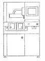
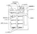
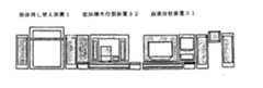
以下、本発明の一実施例を図面を参照しながら説明する。本発明の実施例の検体移し替え装置1の前面からの外観図が図1で、主要部の上面からの概略図が図2である。この検体移し替え装置1は図3のように血液分析装置31と塗抹標本分析装置32との搬送システムに接続され、図示しないコントロールユニットによって制御がなされている。検体としては血液が採血された真空採血管を用いられ、10検体が収められる検体ラックを搬送システムで移送されるように構成されている。
【0009】
主要部には受け取った検体ラック7を搬送するためのコンベアユニット2と、検体を移し替えて収納するための検体収納ラック8を架設する検体収納ラックテーブル6と、検体ラック7にセットされた採血管を取出し、検体収納ラック8に収める検体移し替え部5とが設けられる。
コンベアユニット2は検体ラックを受け取り、装置内を移送させて逆側に送り出すもので、他の搬送ユニットと搬入側、搬出側とも接続できるように構成されている。そして、コンベアユニット2には検体ID読み取り部3とラック固定部4とが設けられている。検体ID読み取り部3はラック押さえ機構部11及び2組みの採血管回転機構部12a,12bとバーコードリーダ13a,13bとからなる。ラック押さえ機構部11とはコンベアユニット2に載って移送される検体ラック7を押さえて止め、バーコードリーダ13a,13bの前に検体ラック中の採血管を位置づけるもので、検体ラック7を採血管ごと間欠的に止めてゆくように制御されている。採血管回転機構部12a,12bとは検体ラック中の採血管に貼付けされたバーコードがどちら向けになっていてもバーコードリーダ13a,13bで読み取りされるように、採血管をゆっくりと軸中心に回転させるものである。このようにバーコードリーダ13及び採血管回転機構部12は二組が同時に読み取り動作がされるように構成されているので、10検体ラックを用いても、効率的に読み取り処理がされる。そして、バーコードリーダ13a,13bは読み取った検体IDの情報をコントロールユニットに送るようにされている。
【0010】
ラック固定部4とはコンベアユニット2で移送される検体ラック7を所定位置に固定する機構部である。これは、検体移し替え部5が採血管を取出す際に検体の位置決めすることと、検体を取出す際にラックが動かないようにするために所定位置に固定しておくようにするものである。
【0011】
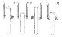
検体移し替え部5とは採血管を検体ラックから取出し検体収納ラックに収めるもので、採血管を掴むハンド部14と、掴んだ採血管を移動させる移動部15とからなる。ハンド部14は種類の異なる採血管が混在しても掴み出せるように採血管を押さえて掴む一組の掴み部17a,17bと、その掴み部17を駆動させる基部16より構成され、掴み部17は掴み手18と掴み腕19とからなる。掴み手18の内側は図7のように採血管の径が12cm(破線)から15.6cm(実線)までのものが混在していても掴めるような凹形状に形成される。掴み腕19は図8のように採血管の長さが異なっても所定高さ位置で掴み手18が採血管を掴めば、採血管のキャップに当たらないようにしたものである。
【0012】
基部16には図9のように掴み部17a,17bを向かい合う方向動かして採血管を掴み離しする駆動源が設けられる。この駆動源としてサーボモータを用いると、サーボモータは掴み部を移動させる位置を設定することができる。その設定位置として採血管の径よりも狭い位置に掴み部が閉じるように設定しておくと、サーボモータは掴み手17a,17bが採血管に接触してもまだ閉じさせようと駆動を続ける。この作用によって掴み部17a,17bは採血管を掴みつづける。この構成を用いると、採血管の大きさが異なっても掴み部17の形状が採血管の形状に対応できれば、同様に採血管を掴むことができる。
移動部15は採血管を検体ラックから取出し、検体収納用ラックに収められるように上下移動と水平移動させるXYZ移動機構が適宜用いられる。
【0013】
検体収納ラックテーブル6は検体収納ラック8を架設するところで、50検体収納できる検体収納ラック8を8個架設することができる。検体収納ラックテーブル6には検体収納ラック8が各位置にセットされているか否か及びセットされている検体収納ラック8のラックIDを装置が識別できるようにされている。検体収納ラックテーブル6の各検体収納ラック8架設位置に孔が5箇所設けられていて、各検体収納用ラック8底部にはこれらの孔と勘合するピンがラックごとに有無が異なるように設けられている。そのことにより、装置が各ピンの有無を認識することで各架設部の検体収納用ラックのセット及びセットされたラックIDを自動的に認識することができるようにされている。
【0014】
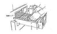
検体収納ラックテーブル6は図10のように装置の前面より引出して取出せるように構成されている。検体移し替え作業中に検体収納ラックを取出す際には、一時停止ボタンを押すと、移し替え作業のきりの良いところで移し替え作業を停止し、検体収納ラックテーブル引き出し可能のメッセージが出るので、そしたら検体収納ラックテーブル引き出して検体収納ラックを交換することができる。
【0015】
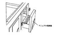
この検体収納ラックテーブルとは別に検体を収納できるマニュアル収納部9が手前に設けられる。このマニュアル収納部9は図11のように、検体収納ラックテーブル6とは独立してマニュアル収納部9だけを前面から引出して、検体を取出したり、収めたりできるようにされている。このマニュアル収納部を用いることで、検体移し替え作業を停止せずに検体を取出したり、収納したりすることができる。
【0016】
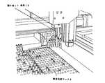
次に、本装置が検体ラックの採血管を並び替えてゆく動作を以下に述べる。分析装置での測定が終わった検体は検体ラック7ごと他の搬送部から移送されてくる。その検体ラック7はコンベアユニット2が受け取り、まず検体ID読み取り部3に移送される。検体ID読み取り部3ではラック押さえ機構11が10検体用の検体ラック7を止め、検体ラック7の一番めと六番めの採血管がバーコードリーダ13a,13bの前にくるように位置づける。そして、採血管回転機構12a,12bがそれぞれの採血管の上に下降してきて、採血管を上から押さえて軸中心にゆっくりと回転させる。バーコードリーダ13a,13bが回転している採血管に貼られたバーコードの読み取りを行う。その採血管の読み取り動作が終了すると採血管回転機構12a,12bが上昇して採血管から離れる。するとラック押さえ機構11が検体ラック7を採血管間隔分だけ移動させて、二番目と七番目の採血管がバーコードリーダ13a,13bの前にくるように位置づける。そして採血管の読み取り動作を同じように行ってゆく。このようにして検体ラック7の各採血管のバーコード読み取りが終了すると、ラック押さえ部11は検体ラック7を離してしまう。
【0017】
そして、検体ラック7はコンベアユニット2により検体ラック固定部4に移送される。検体ラック固定部4が検体ラック7を所定位置に固定する。次に検体移し替え部5が検体ラック固定部4に固定された採血管の位置に移動してくる。ハンド部14は掴み部17a,17bを開いた状態で所定の高さまで下降してきて、掴み部17a,17bを閉じて採血管を掴む。ハンド部14が採血管を掴んだまま上昇して、検体ラック固定部4に固定された検体ラックから採血管を取出す。そしてXYZ移動部15により採血管を掴んだ検体移し替え部5は、読み取られた検体IDに対するホスト部の指示に従い、検体収納ラックテーブル6の所定位置まで移動する。そこでハンド部14は採血管を掴んだまま所定高さまで下降して、検体収納テーブル6に採血管を収納する。そしてハンド部14の掴み手17a,17bを開いて採血管を離し、上昇する。
【0018】
この採血管の移し替え作業を繰り返して、検体ラックの採血管の移し替え作業が終了すれば、検体ラックは検体ラック固定部から解除されて、コンベアユニットによって搬出される。そして搬出部に接続された別の搬送装置や検体ラック収容ユニットに送られる。
本発明の検体移し替え装置では、ひとつのコンベアユニットを常時動かしながら、検体ID読み取り部と検体ラック固定部とに別個に検体ラックを留める機構を備えているので、検体ラックの制御には自由度をもたせながら、検体ID読み取りと検体の移し替えとを同時に並行して行うことができるため、非常に高い処理能力で検体移し替え作業を行うことができる。
【0019】
この検体の収納順はコントロールユニットにより、その施設の運用に応じた任意の順序に設定することができる。例えば、臨床科目ごと内科や産婦人科とかに分けたり、入院や外来とかに分けたり、又検査センターでは集配された地域ごとに分けたりして、検体ID順や患者ID順などに並べられる。
さらに、この並び替え順を分析装置の測定結果をもとにすることもできる。例えば特定項目の測定結果が正常範囲に入らなければ再検査するために別のラックに分けたり、測定結果をいくつかの段階、例えば陰性と弱陽性と強陽性とで検体収納ラックを分けて、所定の順序で並べておくことができる。さらに、これは搬送システムの分析装置の測定結果だけではなく、施設のホストコンピュータに入力された任意の臨床情報を用いることもできる。例えば、他の検査結果や医者の所見、又測定結果を前回値との差を基にして、並べる順序を設定することができる。
【0020】
又、マニュアル収納部9の運用であるが、このマニュアル収納部9は前述したように、検体収納ラックテーブル6と独立してマニュアル収納部9だけを前面から引出して、検体を取出したり収めたりできるようにされている。その取出そうとする検体の選択は検体IDで指定する他、分析装置の測定結果で選択することもできる。例えば測定エラーとなった検体、測定結果がある設定範囲を超えるものなどである。そのように設定された検体は検体ラック7から直接マニュアル収納部9へ、又検体収納ラック8に収められてからマニュアル収納部9へと、検体移し替え手段5によって移される。そして移された検体は移し替え作業中であっても、マニュアル収納部9だけを引出すことによって取出すことができる。
又、検体IDが読み取りできなかった検体を指定して、マニュアル収納部9から取出し、装置に接続されるハンデイスキャナ21で再度IDの読み取りをすることができる。バーコードの破損が著しくハンデイスキャナ21でも検体IDが読み取れない場合は検体IDをマニュアル入力する。そうして検体IDの入力が終わればその採血管を再びマニュアル収納部6に収め、その検体IDに従った検体収納ラック8の位置に移すように指示を出す。その指示に従って、検体移し替え部5がマニュアル収納部9の採血管を検体IDに対応した検体収納ラック8に移し替える。同様に検体搬送ユニットを通さなかった採血管をマニュアル収納部より検体収納ラック8に所定の順序で移し替えることができる。
【0021】
任意の検体収納ラックを保留用に設定することによって運用機能を高めることができる。例えば、検体ID読み取り部3で検体IDが読み取られなかった検体は保留用と指示された検体収納ラックに収納される。又、設定された検体収納ラックが採血管で満杯となり、収める位置がない場合は一旦保留用と指示された検体収納ラックに収納される。そして、その指定された検体収納ラックを空のラックと入れ替えるとそちらのラックに移し替える。このことによって、指定された検体収納ラックだけが満杯になっても移し替え作業を停止せずに継続することができる。
【0022】
【発明の効果】
本発明の検体移し替え装置によって、検体ラックに検体をセットして測定する順序に何ら制限なく、検体容器の種類が混在していても、測定した検体を任意の順序で検体収納ラックに自動的に高い処理能力で移し替えることができる。又、この検体を収める順序を分析装置の測定結果等のデータを基にして移し替えることも可能である。
【図面の簡単な説明】
【図1】本発明の実施例の装置の前面図
【図2】本発明の実施例の装置の主要概略図
【図3】本発明の実施例の装置の搬送システムへの接続図
【図4】本発明の実施例の装置の検体ID読み取り部の図
【図5】本発明の実施例の装置の移し替え作業の図
【図6】本発明の実施例の装置のハンド部の図
【図7】本発明の実施例の装置の掴み手と採血管とを上から見た図
【図8】本発明の実施例の装置の掴み手と掴み腕と採血管を横から見た図
【図9】本発明の実施例の装置のハンド部の図
【図10】本発明の実施例の装置の検体収納ラックテーブル引き出しの図
【図11】本発明の実施例の装置のマニュアル検体収納部引き出しの図[0001]
[Industrial application fields]
The present invention relates to a sample transfer device that takes out a sample such as blood or urine used in a clinical test from a sample rack and places it in a storage rack in a predetermined order, and in particular, is connected to a transport unit that transports the sample rack between analyzers and the like. It is suitable for doing.
[0002]
[Problems to be solved by the invention]
In clinical tests at hospitals and test centers, various tests such as blood tests, biochemical tests, and general tests are performed using biological samples such as blood and urine as specimens. Generally, the analyzers for these examinations include a sampler that automatically measures a sample when placed in a sample rack. Furthermore, in recent years, a transport system that automatically transports specimens between a plurality of analyzers has also been used for efficiency (see: Japanese Patent Laid-Open Nos. 63-217273 and 3-94159). .
[0003]
The specimen examined in this way may have to be used for reexamination or the like depending on the examination result or other examination results. Therefore, the specimen used for the examination is stored for a predetermined period. At that time, it is not time-consuming to store the sample racks as they are tested, but the sample racks are usually 10-sample or 5-sample elongate racks, and can be set up in order so that the racks do not collapse. A storage space must be prepared. The test usually measures the samples in the order of acceptance, interrupts the emergency sample in the middle, or takes out a specific sample, so it is difficult to find the target sample even if arranged in the order of measurement end, In facilities with many specimens, it is difficult to handle emergency tests.
[0004]
Therefore, it is desired to sort samples according to medical subjects or outpatients, or to rearrange them in an appropriate order such as the sample ID order so that the samples that have been measured can be selected immediately. However, performing this operation manually is a difficult operation in a facility with many specimens, and it is not so frequently used in reality.
[0005]
As automation of this work, it is conceivable to devise a conventional sample transport unit and put a unit for rearranging measured sample racks in a predetermined order after the analyzer, but even if rearranged in units of sample racks, If the samples are not arranged in order in the sample rack, the effect is low.
An object of the present invention is to automatically transfer the measured samples to the sample storage rack in a predetermined order without any limitation on the order in which the samples are set in the sample rack.
[0006]
[Means for Solving the Problems]
The present invention has been made in order to achieve the above object, a transport unit for transporting a samplerack specimen was stored after being subjected to the analysis device,the sample at the samplein the sample rack transportedby the transport unit a sample ID reading unit for reading theID, and the sample rack table the sample rack can more erection for accommodating the specimen,the specimen sample ID read by the sample ID reading unit outpreparative sample rack oral,the retrieved sample Itis an object ofthe present invention to provide a sample transfer device provided with a sample transfer means for storing ina sample storage rack and a control unit for controlling the order in whichthe samplestaken out by thesample transfer means are stored inthe sample storage rack.The present invention also includes a transport unit that transports a sample rack that stores a sample after being provided to the analyzer, a sample ID reading unit that reads a sample ID of a sample in the sample rack transported by the transport unit, and a sample A sample storage rack table in which a plurality of sample storage racks can be installed, a sample transfer means for taking out a sample whose sample ID has been read by the sample ID reading unit from the sample rack, and storing the extracted sample in the sample storage rack, and a sample It is an object of the present invention to provide a sample transfer device provided with a control unit for controlling in which sample storage rack the sample taken out by the transfer means is stored.
[0007]
DETAILED DESCRIPTION OF THE INVENTION
The sample used in the sample transfer apparatus according to the present invention is a sample in which a biological sample such as blood or urine is stored in a container such as a blood collection tube or Spitz. The sample rack is a rack in which the sample is accommodated and adapted to the sampler of the analyzer. The sample storage rack to be transferred is a rack for storing samples, and may be a rack that can store 50 samples, 100 samples, or a large number of samples for convenient storage, and can be directly measured by an analyzer. The same sample rack used in the analyzer may be used. The order in which the specimens are stored in this invention includes not only the order in which the specimens are arranged in the storage rack but also the sorting into a plurality of storage racks.
Hereinafter, an embodiment of the present invention will be described with reference to the drawings. FIG. 1 is an external view from the front side of the sample transfer apparatus 1 according to the embodiment of the present invention, and FIG. 2 is a schematic view from the upper surface of the main part. As shown in FIG. 3, the sample transfer device 1 is connected to a transport system of a blood analyzer 31 and a smear sample analyzer 32, and is controlled by a control unit (not shown). The specimen used the vacuum blood collection tube isblood adopted blood and the sample rack to be included is 10 samples is configured to be transported by the transport system.
[0009]
The main part includes a
The
[0010]
The rack fixing unit 4 is a mechanism unit that fixes the sample rack 7 transferred by the
[0011]
The sample transfer unit 5 takes out the blood collection tube from the sample rack and stores it in the sample storage rack, and includes a hand unit 14 for gripping the blood collection tube and a moving unit 15 for moving the gripped blood collection tube. The hand portion 14 is composed of a pair of grip portions 17a and 17b for holding and holding the blood collection tubes so that they can be grasped even when different types of blood collection tubes are mixed, and a
[0012]
As shown in FIG. 9, the
The moving unit 15 appropriately uses an XYZ moving mechanism that takes the blood collection tube from the sample rack and moves it vertically and horizontally so that it can be stored in the sample storage rack.
[0013]
In the specimen storage rack table 6, eight specimen storage racks 8 capable of storing 50 specimens can be installed where the specimen storage rack 8 is installed. In the sample storage rack table 6, the apparatus can identify whether or not the sample storage rack 8 is set at each position and the rack ID of the set sample storage rack 8. Five holes are provided at the installation position of each sample storage rack 8 of the sample storage rack table 6, and pins for fitting with these holes are provided at the bottom of each sample storage rack 8 so that the presence or absence of each rack is different. ing. As a result, when the apparatus recognizes the presence or absence of each pin, it is possible to automatically recognize the set of sample storage racks and the set rack IDs of each installation section.
[0014]
The sample storage rack table 6 is configured to be pulled out from the front surface of the apparatus as shown in FIG. When removing the sample storage rack during the sample transfer operation, if the pause button is pressed, the transfer operation is stopped at a point where the transfer operation is good and a message is displayed indicating that the sample storage rack table can be pulled out. The specimen storage rack can be exchanged by pulling out the specimen storage rack table.
[0015]
In addition to the sample storage rack table, a manual storage unit 9 that can store samples is provided in front. As shown in FIG. 11, the manual storage unit 9 is configured such that only the manual storage unit 9 is pulled out from the front surface independently of the sample storage rack table 6 so that the sample can be taken out and stored. By using this manual storage unit, the sample can be taken out and stored without stopping the sample transfer operation.
[0016]
Next, an operation in which the apparatus rearranges the blood collection tubes of the sample rack will be described below. The sample that has been measured by the analyzer is transferred from another transport unit together with the sample rack 7. The sample rack 7 is received by the
[0017]
Then, the sample rack 7 is transferred to the sample rack fixing unit 4 by the
[0018]
When the transfer operation of the blood collection tube is repeated and the transfer operation of the blood collection tube of the sample rack is completed, the sample rack is released from the sample rack fixing portion and is carried out by the conveyor unit. Then, it is sent to another transport device or sample rack storage unit connected to the carry-out section.
The sample transfer apparatus according to the present invention includes a mechanism for separately holding the sample rack between the sample ID reading unit and the sample rack fixing unit while constantly moving one conveyor unit, and thus has a degree of freedom in controlling the sample rack. Since the sample ID reading and the sample transfer can be performed simultaneously in parallel, the sample transfer operation can be performed with a very high processing capability.
[0019]
The storage order of the samples can be set by the control unit in an arbitrary order according to the operation of the facility. For example, each clinical subject is divided into internal medicine and obstetrics and gynecology, hospitalization and outpatient departments, and the examination center is arranged according to the collected and delivered areas, and is arranged in the order of specimen ID or patient ID.
Furthermore, the rearrangement order can be based on the measurement result of the analyzer. For example, if the measurement result of a specific item does not fall within the normal range, it is divided into separate racks for retesting, or the measurement result is divided into several stages, for example, the sample storage rack is divided into negative, weak positive, and strong positive, They can be arranged in a predetermined order. Furthermore, this can use not only the measurement result of the analyzer of the transport system but also any clinical information input to the host computer of the facility. For example, the order in which other test results, doctor's findings, and measurement results are arranged based on the difference from the previous value can be set.
[0020]
The manual storage unit 9 is operated. As described above, the manual storage unit 9 can draw out and store the sample by pulling out only the manual storage unit 9 from the front surface independently of the sample storage rack table 6. Has been. The specimen to be taken out can be selected not only by the specimen ID but also by the measurement result of the analyzer. For example, there are a sample in which a measurement error has occurred, a measurement result exceeding a certain setting range, and the like. The sample thus set is transferred by the sample transfer means 5 from the sample rack 7 directly to the manual storage unit 9 and from the sample storage rack 8 to the manual storage unit 9. The transferred specimen can be taken out by pulling out only the manual storage unit 9 even during the transfer operation.
In addition, a sample for which the sample ID could not be read can be designated, taken out from the manual storage unit 9, and the ID can be read again by the handy scanner 21 connected to the apparatus. If the barcode is so severely damaged that the handy scanner 21 cannot read the sample ID, the sample ID is manually input. When the input of the sample ID is finished, the instruction is given to store the blood collection tube in the manual storage unit 6 again and move it to the position of the sample storage rack 8 according to the sample ID. In accordance with the instruction, the sample transfer unit 5 transfers the blood collection tube of the manual storage unit 9 to the sample storage rack 8 corresponding to the sample ID. Similarly, blood collection tubes that have not passed through the sample transport unit can be transferred from the manual storage unit to the sample storage rack 8 in a predetermined order.
[0021]
The operation function can be enhanced by setting an arbitrary sample storage rack for holding. For example, a sample whose sample ID is not read by the sample ID reading unit 3 is stored in a sample storage rack instructed to be held. If the set sample storage rack is full of blood collection tubes and there is no storage position, the sample storage rack is temporarily stored in the sample storage rack instructed to be held. Then, when the designated sample storage rack is replaced with an empty rack, the rack is transferred to that rack. Thus, even if only the designated sample storage rack is full, the transfer operation can be continued without stopping.
[0022]
【The invention's effect】
With the sample transfer device of the present invention, there is no limitation on the order in which samples are set in the sample rack and the sample is automatically placed in the sample storage rack in any order even if sample container types are mixed. Can be transferred with high processing capacity. It is also possible to change the order in which the specimens are stored based on data such as measurement results of the analyzer.
[Brief description of the drawings]
1 is a front view of an apparatus according to an embodiment of the present invention. FIG. 2 is a main schematic diagram of an apparatus according to an embodiment of the present invention. FIG. 3 is a connection diagram of an apparatus according to an embodiment of the present invention to a transport system. FIG. 5 is a diagram of the sample ID reading unit of the apparatus of the embodiment of the present invention. FIG. 5 is a diagram of the transfer operation of the apparatus of the embodiment of the present invention. 7] A view of the gripper and blood collection tube of the apparatus of the embodiment of the present invention as viewed from above. [FIG. 9 is a drawing of the hand portion of the apparatus of the embodiment of the present invention. FIG. 10 is a drawing of the specimen storage rack table drawer of the apparatus of the embodiment of the present invention. Figure of
Claims (9)
Translated fromJapaneseとを特徴とする請求項7に記載の検体移し替え装置。 The specimen transfer apparatus according to claim 7, wherein:
Priority Applications (2)
| Application Number | Priority Date | Filing Date | Title |
|---|---|---|---|
| JP13494299AJP4136187B2 (en) | 1999-05-14 | 1999-05-14 | Sample transfer device |
| US09/570,065US6255614B1 (en) | 1999-05-14 | 2000-05-12 | Specimen-container transfer apparatus |
Applications Claiming Priority (1)
| Application Number | Priority Date | Filing Date | Title |
|---|---|---|---|
| JP13494299AJP4136187B2 (en) | 1999-05-14 | 1999-05-14 | Sample transfer device |
Publications (2)
| Publication Number | Publication Date |
|---|---|
| JP2000321287A JP2000321287A (en) | 2000-11-24 |
| JP4136187B2true JP4136187B2 (en) | 2008-08-20 |
Family
ID=15140169
Family Applications (1)
| Application Number | Title | Priority Date | Filing Date |
|---|---|---|---|
| JP13494299AExpired - LifetimeJP4136187B2 (en) | 1999-05-14 | 1999-05-14 | Sample transfer device |
Country Status (2)
| Country | Link |
|---|---|
| US (1) | US6255614B1 (en) |
| JP (1) | JP4136187B2 (en) |
Families Citing this family (92)
| Publication number | Priority date | Publication date | Assignee | Title |
|---|---|---|---|---|
| JP2005531540A (en)* | 2002-04-30 | 2005-10-20 | トラスティーズ・オブ・タフツ・カレッジ | Smart prodrug of serine protease inhibitor |
| US7487061B2 (en)* | 2002-05-23 | 2009-02-03 | Sysmex Corporation | Sample analyzer |
| DE10306400A1 (en)* | 2003-02-15 | 2004-09-02 | Arzneimittel Gmbh Apotheker Vetter & Co. Ravensburg | Method for identifying and / or monitoring medical syringes, in particular prefilled pre-filled syringes |
| US20050169733A1 (en)* | 2004-01-29 | 2005-08-04 | Drynkin Alexander V. | Automated tube handler system |
| US7494168B1 (en) | 2005-01-19 | 2009-02-24 | David Miller | Test tube picker for rack stored test tubes |
| JP4768409B2 (en) | 2005-11-15 | 2011-09-07 | シスメックス株式会社 | Sample analysis apparatus, sample analysis main body apparatus, and sample container supply apparatus |
| JP2007309675A (en)* | 2006-05-16 | 2007-11-29 | Olympus Corp | Sample rack supply-and-recovery system |
| JP2009222535A (en)* | 2008-03-17 | 2009-10-01 | Hitachi High-Technologies Corp | Autoanalyzer |
| EP2148204B1 (en)* | 2008-07-25 | 2013-01-02 | F. Hoffmann-La Roche AG | A laboratory storage and retrieval system and a method to handle laboratory sample tubes |
| US8176747B2 (en)* | 2008-07-31 | 2012-05-15 | Hamilton Storage Technologies, Inc. | Tube picking mechanism for an automated, ultra-low temperature storage and retrieval system |
| US8459462B2 (en)* | 2008-10-10 | 2013-06-11 | Quest Diagnostics Investments Incorporated | System and method for sorting specimen |
| ES2809179T3 (en) | 2008-11-14 | 2021-03-03 | Becton Dickinson Co | Universal container holder |
| DE102009046662A1 (en)* | 2009-11-12 | 2011-05-19 | Robert Bosch Gmbh | Device for removing containers |
| JP5372732B2 (en)* | 2009-12-28 | 2013-12-18 | シスメックス株式会社 | Sample analyzer and sample rack transport method |
| DE102010028769A1 (en) | 2010-05-07 | 2011-11-10 | Pvt Probenverteiltechnik Gmbh | System for transporting containers between different stations and container carriers |
| EP3919915A1 (en) | 2010-05-24 | 2021-12-08 | Hitachi High-Tech Corporation | Sample test automation system |
| JP5425728B2 (en)* | 2010-07-15 | 2014-02-26 | 株式会社日立ハイテクノロジーズ | Sample processing system |
| US8956568B2 (en) | 2010-09-03 | 2015-02-17 | Hitachi High-Technologies Corporation | Sample transfer mechanism |
| US9163869B2 (en) | 2010-09-09 | 2015-10-20 | Hamilton Storage Technologies, Inc. | Tube picking mechanisms with an ultra-low temperature or cryogenic picking compartment |
| US20120060520A1 (en) | 2010-09-10 | 2012-03-15 | Hamilton Storage Technologies, Inc. | Input/Output Module and Overall Temperature Control of Samples |
| JP5784294B2 (en)* | 2010-09-22 | 2015-09-24 | シスメックス株式会社 | Cell analysis apparatus and cell analysis method |
| EP2589967A1 (en) | 2011-11-04 | 2013-05-08 | Roche Diagnostics GmbH | Laboratory sample distribution system and corresponding method of operation |
| EP2589966A1 (en) | 2011-11-04 | 2013-05-08 | Roche Diagnostics GmbH | Laboratory sample distribution system and corresponding method of operation |
| EP2589968A1 (en) | 2011-11-04 | 2013-05-08 | Roche Diagnostics GmbH | Laboratory sample distribution system, laboratory system and method of operating |
| JP6054726B2 (en)* | 2011-12-06 | 2016-12-27 | 平田機工株式会社 | Sorting device |
| JP6230915B2 (en)* | 2011-12-28 | 2017-11-15 | 株式会社日立ハイテクノロジーズ | Sample transfer device and system |
| ES2545626T3 (en)* | 2012-01-27 | 2015-09-14 | Glp Systems Gmbh | Storage cartridge |
| JP6042130B2 (en)* | 2012-07-31 | 2016-12-14 | シスメックス株式会社 | Specimen transfer device, specimen processing system, and specimen transfer method |
| JP6169337B2 (en)* | 2012-09-03 | 2017-07-26 | 株式会社日立ハイテクノロジーズ | Sample test automation system and sample transport method |
| CN104583778B (en)* | 2012-09-12 | 2016-06-08 | 株式会社日立高新技术 | Corpse or other object for laboratory examination and chemical testing storage device, sample treatment system with stopper shape detection and their control method |
| JP6009881B2 (en)* | 2012-09-20 | 2016-10-19 | シスメックス株式会社 | Specimen transfer device and specimen processing system |
| JP6022285B2 (en)* | 2012-09-28 | 2016-11-09 | シスメックス株式会社 | Specimen storage device, specimen storage method, and specimen inspection system |
| ES2643180T3 (en)* | 2012-10-24 | 2017-11-21 | F. Hoffmann-La Roche Ag | System and method to locate sample containers |
| JP6088791B2 (en)* | 2012-10-30 | 2017-03-01 | あおい精機株式会社 | Chucking device |
| US20140145574A1 (en)* | 2012-11-28 | 2014-05-29 | Michael Paul Henne | Endless Chain Frozen Vial Storage Module |
| CN103983797B (en) | 2013-01-31 | 2018-05-04 | 希森美康株式会社 | Classfication of containers device, sample processing system and Classfication of containers method |
| DE102014202843B3 (en) | 2014-02-17 | 2014-11-06 | Roche Pvt Gmbh | Transport device, sample distribution system and laboratory automation system |
| DE102014202838B3 (en) | 2014-02-17 | 2014-11-06 | Roche Pvt Gmbh | Transport device, sample distribution system and laboratory automation system |
| EP2927695B1 (en) | 2014-03-31 | 2018-08-22 | Roche Diagniostics GmbH | Sample distribution system and laboratory automation system |
| EP2927168A1 (en) | 2014-03-31 | 2015-10-07 | Roche Diagniostics GmbH | Transport device, sample distribution system and laboratory automation system |
| EP2927163B1 (en) | 2014-03-31 | 2018-02-28 | Roche Diagnostics GmbH | Vertical conveyor, sample distribution system and laboratory automation system |
| EP2927167B1 (en) | 2014-03-31 | 2018-04-18 | F. Hoffmann-La Roche AG | Dispatch device, sample distribution system and laboratory automation system |
| EP2927625A1 (en) | 2014-03-31 | 2015-10-07 | Roche Diagniostics GmbH | Sample distribution system and laboratory automation system |
| EP2957914B1 (en) | 2014-06-17 | 2018-01-03 | Roche Diagnostics GmbH | Laboratory sample distribution system and laboratory automation system |
| EP2977766A1 (en) | 2014-07-24 | 2016-01-27 | Roche Diagniostics GmbH | Laboratory sample distribution system and laboratory automation system |
| EP2995960B1 (en) | 2014-09-09 | 2020-07-15 | Roche Diagniostics GmbH | Laboratory sample distribution system and method for calibrating magnetic sensors |
| EP2995580A1 (en) | 2014-09-09 | 2016-03-16 | Roche Diagniostics GmbH | Laboratory sample distribution system and laboratory automation system |
| US9952242B2 (en)* | 2014-09-12 | 2018-04-24 | Roche Diagnostics Operations, Inc. | Laboratory sample distribution system and laboratory automation system |
| EP2995958A1 (en) | 2014-09-15 | 2016-03-16 | Roche Diagniostics GmbH | Method of operating a laboratory sample distribution system, laboratory sample distribution system and laboratory automation system |
| EP3006943B1 (en) | 2014-10-07 | 2020-04-22 | Roche Diagniostics GmbH | Module for a laboratory sample distribution system, laboratory sample distribution system and laboratory automation system |
| EP3016116A1 (en) | 2014-11-03 | 2016-05-04 | Roche Diagniostics GmbH | Printed circuit board arrangement, coil for a laboratory sample distribution system, laboratory sample distribution system and laboratory automation system |
| EP3070479B1 (en) | 2015-03-16 | 2019-07-03 | Roche Diagniostics GmbH | Transport carrier, laboratory cargo distribution system and laboratory automation system |
| EP3073270B1 (en) | 2015-03-23 | 2019-05-29 | Roche Diagniostics GmbH | Laboratory sample distribution system and laboratory automation system |
| US10551398B2 (en)* | 2015-04-27 | 2020-02-04 | Hitachi High-Technologies Corporation | Specimen container inclination correction mechanism, and method for controlling same |
| EP3095739A1 (en) | 2015-05-22 | 2016-11-23 | Roche Diagniostics GmbH | Method of operating a laboratory sample distribution system, laboratory sample distribution system and laboratory automation system |
| EP3096146A1 (en) | 2015-05-22 | 2016-11-23 | Roche Diagniostics GmbH | Method of operating a laboratory sample distribution system, laboratory sample distribution system and laboratory automation system |
| EP3096145B1 (en) | 2015-05-22 | 2019-09-04 | Roche Diagniostics GmbH | Method of operating a laboratory automation system and laboratory automation system |
| EP3112874A1 (en) | 2015-07-02 | 2017-01-04 | Roche Diagnostics GmbH | Storage module, method of operating a laboratory automation system and laboratory automation system |
| EP3121603A1 (en) | 2015-07-22 | 2017-01-25 | Roche Diagnostics GmbH | Sample container carrier, laboratory sample distribution system and laboratory automation system |
| EP3139175B1 (en) | 2015-09-01 | 2021-12-15 | Roche Diagnostics GmbH | Laboratory cargo distribution system, laboratory automation system and method of operating a laboratory cargo distribution system |
| EP3153866A1 (en) | 2015-10-06 | 2017-04-12 | Roche Diagnostics GmbH | Method of determining a handover position and laboratory automation system |
| EP3153867B1 (en) | 2015-10-06 | 2018-11-14 | Roche Diagniostics GmbH | Method of configuring a laboratory automation system, laboratory sample distribution system and laboratory automation system |
| EP3156352B1 (en) | 2015-10-13 | 2019-02-27 | Roche Diagniostics GmbH | Laboratory sample distribution system and laboratory automation system |
| EP3156353B1 (en) | 2015-10-14 | 2019-04-03 | Roche Diagniostics GmbH | Method of rotating a sample container carrier, laboratory sample distribution system and laboratory automation system |
| EP3211429A1 (en) | 2016-02-26 | 2017-08-30 | Roche Diagnostics GmbH | Transport device having a tiled driving surface |
| EP3211430A1 (en) | 2016-02-26 | 2017-08-30 | Roche Diagnostics GmbH | Transport device with base plate modules |
| EP3211428A1 (en) | 2016-02-26 | 2017-08-30 | Roche Diagnostics GmbH | Transport device unit for a laboratory sample distribution system |
| CN109196363A (en) | 2016-06-03 | 2019-01-11 | 豪夫迈·罗氏有限公司 | Laboratory sample distribution system and laboratory automation system |
| EP3255519B1 (en) | 2016-06-09 | 2019-02-20 | Roche Diagniostics GmbH | Laboratory sample distribution system and method of operating a laboratory sample distribution system |
| EP3260867A1 (en) | 2016-06-21 | 2017-12-27 | Roche Diagnostics GmbH | Method of setting a handover position and laboratory automation system |
| JP6752350B2 (en) | 2016-08-04 | 2020-09-09 | エフ.ホフマン−ラ ロシュ アーゲーF. Hoffmann−La Roche Aktiengesellschaft | Laboratory sample distribution system and laboratory automation system |
| EP3330717B1 (en) | 2016-12-01 | 2022-04-06 | Roche Diagnostics GmbH | Laboratory sample distribution system and laboratory automation system |
| EP3343232B1 (en) | 2016-12-29 | 2021-09-15 | Roche Diagnostics GmbH | Laboratory sample distribution system and laboratory automation system |
| EP3355065B1 (en) | 2017-01-31 | 2021-08-18 | Roche Diagnostics GmbH | Laboratory sample distribution system and laboratory automation system |
| EP3357842B1 (en) | 2017-02-03 | 2022-03-23 | Roche Diagnostics GmbH | Laboratory automation system |
| EP3410123B1 (en) | 2017-06-02 | 2023-09-20 | Roche Diagnostics GmbH | Method of operating a laboratory sample distribution system, laboratory sample distribution system and laboratory automation system |
| EP3428653B1 (en) | 2017-07-13 | 2021-09-15 | Roche Diagnostics GmbH | Method of operating a laboratory sample distribution system, laboratory sample distribution system and laboratory automation system |
| EP3456415B1 (en) | 2017-09-13 | 2021-10-20 | Roche Diagnostics GmbH | Sample container carrier, laboratory sample distribution system and laboratory automation system |
| EP3457144B1 (en) | 2017-09-13 | 2021-10-20 | Roche Diagnostics GmbH | Sample container carrier, laboratory sample distribution system and laboratory automation system |
| SE541776C2 (en)* | 2017-11-10 | 2019-12-10 | Il Granito Ab | Identifying, sorting and manipulating test tubes |
| EP3537159B1 (en) | 2018-03-07 | 2022-08-31 | Roche Diagnostics GmbH | Method of operating a laboratory sample distribution system, laboratory sample distribution system and laboratory automation system |
| EP3540443B1 (en) | 2018-03-16 | 2023-08-30 | Roche Diagnostics GmbH | Laboratory system, laboratory sample distribution system and laboratory automation system |
| CN112204403A (en)* | 2018-06-28 | 2021-01-08 | 深圳迈瑞生物医疗电子股份有限公司 | A kind of sample testing method and sample analysis device |
| CN109939944B (en)* | 2019-03-21 | 2024-05-28 | 上海创司杰医疗科技有限公司 | Full-automatic heparin tube letter sorting system |
| EP3925911B1 (en) | 2020-06-19 | 2023-05-24 | Roche Diagnostics GmbH | Laboratory sample distribution system and corresponding method of operation |
| EP3940388B1 (en) | 2020-07-15 | 2024-04-10 | Roche Diagnostics GmbH | Laboratory sample distribution system and method for operating the same |
| EP4001923B1 (en) | 2020-11-23 | 2024-06-05 | Roche Diagnostics GmbH | Laboratory sample distribution system and laboratory automation system |
| US11747356B2 (en) | 2020-12-21 | 2023-09-05 | Roche Diagnostics Operations, Inc. | Support element for a modular transport plane, modular transport plane, and laboratory distribution system |
| JP2023103899A (en)* | 2022-01-14 | 2023-07-27 | シスメックス株式会社 | CONTAINER TRANSFER METHOD AND CONTAINER TRANSFER DEVICE |
| WO2023217815A1 (en) | 2022-05-12 | 2023-11-16 | F. Hoffmann-La Roche Ag | Method for operating a sorter device in an ivd laboratory system and ivd laboratory system |
| CN120693524A (en)* | 2023-04-11 | 2025-09-23 | 株式会社日立高新技术 | Container storage device, analysis system, and container transfer method |
| CN117842505A (en)* | 2024-01-31 | 2024-04-09 | 基点生物科技(上海)有限公司 | Biological sample storage system and control method and device thereof |
Family Cites Families (2)
| Publication number | Priority date | Publication date | Assignee | Title |
|---|---|---|---|---|
| JP2769026B2 (en)* | 1990-07-16 | 1998-06-25 | 三菱化学エンジニアリング株式会社 | Sample sorting device |
| DE19819813C2 (en)* | 1998-05-04 | 2000-11-02 | Olympus Diagnostica Gmbh | Use of a laboratory primary sample distributor for archiving |
- 1999
- 1999-05-14JPJP13494299Apatent/JP4136187B2/ennot_activeExpired - Lifetime
- 2000
- 2000-05-12USUS09/570,065patent/US6255614B1/ennot_activeExpired - Lifetime
Also Published As
| Publication number | Publication date |
|---|---|
| JP2000321287A (en) | 2000-11-24 |
| US6255614B1 (en) | 2001-07-03 |
Similar Documents
| Publication | Publication Date | Title |
|---|---|---|
| JP4136187B2 (en) | Sample transfer device | |
| US6919044B1 (en) | Sample loading and handling interface to multiple chemistry analyzers | |
| JP2973133B2 (en) | Sample sorting device for clinical test | |
| JP4960352B2 (en) | Automatic method for preparing a whole blood sample for analysis and automatic apparatus for carrying out the method | |
| CN110383034B (en) | System and method for automatically preparing biological sample | |
| CA2125526C (en) | Transport system for fluid analysis instrument | |
| JP3068286B2 (en) | Analyzer, test element support for analyzer, and method for cleaning test element | |
| JP5058134B2 (en) | Inspection robot | |
| CN115427780B (en) | Automatic biological sample extraction system and device | |
| CN110320361A (en) | Subject pretreatment unit, mechanical arm and subject preprocess method | |
| JP2001124786A (en) | Sample sorting device | |
| JP2002014109A (en) | Pretreatment device for specimen inspection | |
| JPH05142232A (en) | Specimen allocating system for clinical | |
| JP2002040034A (en) | Specimen sorting device | |
| JP2010223853A (en) | Sample tube opening device | |
| JPS63271164A (en) | Automatic biochemical analysis system | |
| JP3226233B2 (en) | Automatic analyzer | |
| JP2707088B2 (en) | Container transfer method and apparatus | |
| EP2901164A1 (en) | Method and device for delivering fluid sample to analyzing apparatus | |
| CN111989558A (en) | Sample processing system and method for automated processing of histological samples | |
| JPH11258248A (en) | Sample transport method and apparatus | |
| CN218594851U (en) | Detection reagent storage rack for endoscope | |
| CN213875104U (en) | Blood sample reserving device | |
| JP3748997B2 (en) | Automatic analyzer | |
| JPS63236966A (en) | Automatic sample transport device |
Legal Events
| Date | Code | Title | Description |
|---|---|---|---|
| A621 | Written request for application examination | Free format text:JAPANESE INTERMEDIATE CODE: A621 Effective date:20060511 | |
| A977 | Report on retrieval | Free format text:JAPANESE INTERMEDIATE CODE: A971007 Effective date:20080117 | |
| A131 | Notification of reasons for refusal | Free format text:JAPANESE INTERMEDIATE CODE: A131 Effective date:20080205 | |
| A521 | Request for written amendment filed | Free format text:JAPANESE INTERMEDIATE CODE: A523 Effective date:20080318 | |
| A521 | Request for written amendment filed | Free format text:JAPANESE INTERMEDIATE CODE: A523 Effective date:20080404 | |
| TRDD | Decision of grant or rejection written | ||
| A01 | Written decision to grant a patent or to grant a registration (utility model) | Free format text:JAPANESE INTERMEDIATE CODE: A01 Effective date:20080520 | |
| A01 | Written decision to grant a patent or to grant a registration (utility model) | Free format text:JAPANESE INTERMEDIATE CODE: A01 | |
| A61 | First payment of annual fees (during grant procedure) | Free format text:JAPANESE INTERMEDIATE CODE: A61 Effective date:20080603 | |
| R150 | Certificate of patent or registration of utility model | Free format text:JAPANESE INTERMEDIATE CODE: R150 | |
| FPAY | Renewal fee payment (event date is renewal date of database) | Free format text:PAYMENT UNTIL: 20110613 Year of fee payment:3 | |
| FPAY | Renewal fee payment (event date is renewal date of database) | Free format text:PAYMENT UNTIL: 20110613 Year of fee payment:3 | |
| FPAY | Renewal fee payment (event date is renewal date of database) | Free format text:PAYMENT UNTIL: 20140613 Year of fee payment:6 | |
| R250 | Receipt of annual fees | Free format text:JAPANESE INTERMEDIATE CODE: R250 | |
| R250 | Receipt of annual fees | Free format text:JAPANESE INTERMEDIATE CODE: R250 | |
| EXPY | Cancellation because of completion of term |