JP4131372B2 - Biological monitor device - Google Patents
Biological monitor deviceDownload PDFInfo
- Publication number
- JP4131372B2 JP4131372B2JP2002083013AJP2002083013AJP4131372B2JP 4131372 B2JP4131372 B2JP 4131372B2JP 2002083013 AJP2002083013 AJP 2002083013AJP 2002083013 AJP2002083013 AJP 2002083013AJP 4131372 B2JP4131372 B2JP 4131372B2
- Authority
- JP
- Japan
- Prior art keywords
- living body
- electrode
- signal
- contact
- support
- Prior art date
- Legal status (The legal status is an assumption and is not a legal conclusion. Google has not performed a legal analysis and makes no representation as to the accuracy of the status listed.)
- Expired - Fee Related
Links
- 238000001514detection methodMethods0.000claimsdescription28
- 238000012545processingMethods0.000claimsdescription13
- 230000000241respiratory effectEffects0.000claimsdescription8
- 230000029058respiratory gaseous exchangeEffects0.000claimsdescription7
- 238000012544monitoring processMethods0.000claimsdescription2
- 230000000694effectsEffects0.000description13
- 230000036760body temperatureEffects0.000description9
- 238000010586diagramMethods0.000description8
- 230000010355oscillationEffects0.000description8
- 230000036387respiratory rateEffects0.000description8
- 238000000034methodMethods0.000description4
- 230000002159abnormal effectEffects0.000description3
- 230000001133accelerationEffects0.000description3
- 238000005259measurementMethods0.000description3
- 210000000038chestAnatomy0.000description2
- OKTJSMMVPCPJKN-UHFFFAOYSA-NCarbonChemical compound[C]OKTJSMMVPCPJKN-UHFFFAOYSA-N0.000description1
- 230000004071biological effectEffects0.000description1
- 229910052799carbonInorganic materials0.000description1
- 239000011248coating agentSubstances0.000description1
- 238000000576coating methodMethods0.000description1
- 238000004891communicationMethods0.000description1
- 230000007423decreaseEffects0.000description1
- 230000005484gravityEffects0.000description1
- 239000000463materialSubstances0.000description1
- QSHDDOUJBYECFT-UHFFFAOYSA-NmercuryChemical compound[Hg]QSHDDOUJBYECFT-UHFFFAOYSA-N0.000description1
- 229910052753mercuryInorganic materials0.000description1
- 229910052751metalInorganic materials0.000description1
- 239000002184metalSubstances0.000description1
- 238000012806monitoring deviceMethods0.000description1
- 230000036544postureEffects0.000description1
- 229920003002synthetic resinPolymers0.000description1
- 239000000057synthetic resinSubstances0.000description1
Images


Landscapes
- Measuring Pulse, Heart Rate, Blood Pressure Or Blood Flow (AREA)
- Measurement Of The Respiration, Hearing Ability, Form, And Blood Characteristics Of Living Organisms (AREA)
- Measuring And Recording Apparatus For Diagnosis (AREA)
- Measurement And Recording Of Electrical Phenomena And Electrical Characteristics Of The Living Body (AREA)
Description
Translated fromJapanese【0001】
【発明が属する技術分野】
この発明は、下着等の衣類に装着し、心電図、呼吸数、体温、脈拍数、体位検出、生体の活動度等の生体データを長時間検出することができると共に、これらのデータを電送することができる生体モニタ装置に関する。
【0002】
【従来の技術】
本出願人は、特開2001−299712号において、下着等に装着テープ、ホック、ポケットにより取付けることができ、長時間、心電図、呼吸、体温、体位及び活動量をモニタリングできる装置を開示した。この装置は、本体ケースに、一対の心電図電極と、呼吸数及び脈拍数とを検出する静電容量検出部と、体温を検出する温度センサと、体位を検出するセンサと、活動度を検出する加速度センサとを少なくとも具備し、さらに、これらによる測定データを電送する無線テレメータを具備するものである。特に、静電容量検出部は、生体に対して絶縁された電極を有し、呼吸・脈拍等に基づく生体の動きによって変動する生体・電極間の静電容量の変動を検出し、この信号から呼吸数・脈拍数を検出するようにしたものである。
【0003】
【発明が解決しようする課題】
本発明は、上記特開2001−299712号に開示される発明をさらに改良し、生体モニタ装置の装着性及び装着感を向上させた生体モニタ装置を提供することにある。
【0004】
【課題を解決するための手段】
したがって、この発明は、生体に接触する接触電極と、生体に対して所定の間隔で非接触である非接触電極と、生体に接触するコモン電極とを少なくとも具備し、さらに、本体ケース内に、前記接触電極から心電図信号を検出する心電図検出部と、前記非接触電極と生体との間に生じる静電容量の変化を検出して呼吸及び脈拍を検出する呼吸脈拍検出部と、前記心電図検出部によって検出された信号及び呼吸脈拍検出部によって検出された信号を変換して演算処理する信号処理部と、該信号処理部によって演算された信号を記憶する記憶部と、前記信号処理部によって演算された信号を出力する信号出力部と、信号出力部から出力される信号を発信する無線出力部とを少なくとも具備する生体モニタ装置において、前記本体ケースから所定の間隔で延出し、前記生体に直接装着する衣類の端部に跨って前記本体ケースを支持する複数の支持部と、該支持部の少なくとも一つから延出する電極アーム部とを具備すると共に、前記コモン電極は、少なくとも一つの支持部の生体と接触する部分に設けられ、前記接触電極は、前記電極アーム部の端部近傍の前記生体との接触部分に設けられることにある。これによって、生体モニタ装置を下着等の衣類の装着するだけで接触電極及びコモン電極を所定の位置において生体に接触させることができる。
【0005】
さらに、この発明において、前記コモン電極は、複数の支持部の中央に位置する支持部に形成されることが望ましく、前記電極アーム部は、複数の支持部の両最外部に位置する支持部のそれぞれに形成されることが望ましい。
【0006】
さらにまた、前記コモン電極と前記接触電極の距離は、5cm〜15cmの範囲内に設定されることが望ましい。
【0007】
また、前記非接触電極は、前記本体ケースの生体側側面であって、前記支持部間に設けられると共に、前記支持部が跨る衣類によって前記生体と非接触であることが望ましい。また、前記非接触電極は、前記コモン電極が設けられる支持部と、前記接触電極が設けられる支持部との間に位置する支持部に設けられ、該接触電極と生体との間に非導電部が形成されるものであってもよい。
【0008】
さらに、前記支持部の一つの生体と接触する部分には、温度センサが設けられルことが望ましい。さらにまた、前記本体ケースには、生体の3次元移動を検出する体位検出手段が形成されることが望ましい。
【0009】
【発明の実施の形態】
以下、この発明の実施の形態について図面を参照して説明する。
【0010】
図1(a),(b),(c),(d)で示される生体モニタ装置1は、本体ケース2と、本体ケース2を衣類10、特にパンツ等に下着に支持するための支持部3と、両外側に位置する支持部3から横方に延出する電極アーム部4とによって構成される。
【0011】
前記支持部3は、前記本体ケース2の上端部から衣類10の端部を跨るように形成されるもので、その先端部分が生体20に接触することが望ましい。これによって、例えば、生体モニタ装置1をパンツに装着する場合、本体ケース2はパンツの外側に位置し、保持部3がパンツの端部を跨って、前記支持部3の先端側面及び電極アーム部4がパンツの内側に位置して生体20と接触するものである。
【0012】
また、それぞれの電極アーム部4の先端部近傍には心電図電極5が設けられ、それぞれの心電図電極5は前記電極アーム部4及び前記支持部3に貼り付けられた導電部(図示せず)又は電極アーム部4及び支持部3内部に埋め込まれた導電部(図示せず)を介して前記本体ケース2の内部に配設された電気回路30と接続されるものである。この心電図電極5は、金属、導電ゴム又は導電性カーボンで形成されるものであるが、生体との接触感触の良好性から言えば、導電ゴムで形成されることが望ましい。また、前記心電図電極5とコモン電極6との間の距離D1,D2は、5cm〜15cmの間の距離に設定されることが望ましい。
【0013】
コモン電極6は、中央に位置する支持部3の生体との接触面に形成され、前記心電図電極5と同質の材料で形成されることが望ましい。また、このコモン電極6は、支持部3に貼り付けられた導電部(図示せず)を介して前記本体ケース2に配設された電気回路30と接続されるものである。
【0014】
さらに、本体ケース2の生体側側面2aには2つの非接触電極7が設けられ、本体ケース2を前記衣類10に装着した場合、生体20との間に所定の間隔d1が形成される。
【0015】
また、前記支持部3の一つの生体20との接触面には、温度検出センサ8が設けられ、前記支持部3を介して前記電気回路30と接続される。
【0016】
前記本体ケース2の前面には、2つの押下スイッチ9が形成される。この押下スイッチ9の先端は、前記本体ケース2の前面よりも凹んでおり、上着やベルト等によって押下されることを防止するものである。また、この押下スイッチ9は心電図情報等の測定情報を緊急に電送するために設けられるもので、誤報を防止するために2つの押下スイッチ9が同時に押下された場合にのみ電送させるようになっているものである。
【0017】
前記電気回路30は、例えば図2に示すもので、前記心電図電極5からの信号から心電図信号をデジタル信号として出力する心電図検出部35と、前記温度検出センサ8からの信号から体温信号をデジタル信号として出力する体温検出部36と、加速度検出センサ31からの信号から活動度信号をデジタル信号として出力する活動度検出部37と、前記非接触電極7からの静電容量の変化に基づいて呼吸数及び脈拍数信号をデジタル信号として出力する呼吸数・脈拍数検出部38と、体の傾きを検出する3つのセンサ32,33,34からの信号から被験者の体位を検出する体位検出部39と、上述した検出部35,36,37,38,39からのデジタル信号を波形処理する波形処理部40と、この波形処理部40によってノイズ等が除去されたデジタル信号を生体測定データに加工する信号演算部41と、この信号演算部41によって演算加工された生体測定データを記憶して蓄積する記憶部42と、この記憶部42によって蓄積された記憶を所定時間毎に記録する記録部43と、この記録部43に記録された生体測定データを定期的に、また押下スイッチ9の押下によって前記信号演算部41によって演算された最新の生体測定データを出力する信号出力部44と、この信号出力部44から出力された生体測定データを無線出力する無線出力部45と、ボタン電池等から電力を供給する電源部47と、アンテナ46とによって少なくとも構成される。
【0018】
前記心電図検出部35では、前記心電図電極5で得られた信号が増幅及びフィルタ処理され、デジタル信号Aに変換される。そして、このデジタル信号Aは波形処理部40において、例えば、図3(a)で示すように、ノイズフィルタ(低域除去フィルタ及び高域除去フィルタ、又はハムノイズ除去フィルタ)によってノイズ成分を除去し、明瞭な心電図信号Cを得ることができるものである。また、図3(b)に示すように、心電図信号Bには筋電図信号が重畳している場合等には、筋電図フィルタ等によって心電図以外の周波数成分を除去し、明瞭な心電図信号Cが得られるものである。この心電図信号Cは、信号演算部41を介して記憶部42に一時的に記憶され、また信号演算部41において実時間心電図解析処理がなされ、検出された心電図信号Cが正常心電図波形か異常波形かが判定され、異常波形と判定された場合には記憶部42に記憶された心電図波形を異常波形として発生時間等を付加して記録部43に記録する。
【0019】
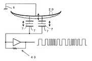
図4で示すように、非接触電極7は、生体20の間で静電容量を構成する。この非接触電極7と生体20との間の静電容量は、呼吸及び脈拍による生体の動きや微動によって変化する。したがって、呼吸数・脈拍数検出部38では、この静電容量の変化による発振周波数の変化を発振回路40を介して検出する。具体的には、呼気の場合、生体20が破線から実線方向に移動することから胸郭の容積は小さくなり生体20と非接触電極7の間の空隙は大きくなることから静電容量が減少するので、発振周波数は高くなる。また吸気の場合には、生体20が実線から破線方向に移動することから胸郭の容積は大きくなり生体20と非接触電極7の間の空隙は小さくなることから静電容量が増加するので、発振周波数は低くなる。この発振周波数の変動は、波形処理部40において波形化されて、呼吸波形と脈拍波形に分離され、それぞれが信号演算部41において処理されて、呼吸数及び脈拍数が演算され、記憶部42に記憶する。必要に応じて、呼吸波形・脈拍波形を記憶部42を介して記録部43に保存するようにしても良いものである。尚、図5で示すように、発振周波数の変動を示す波形において、Btが呼吸周期であり、Ptが脈拍周期である。
【0020】
また、前記発振周波数の変動を、カウンタ回路によってカウントして呼吸及び脈波が重畳したデジタル信号として検出し、この信号を0.5秒(2Hz)から10秒(0.1Hz)の範囲のデジタル信号が通過する第1のデジタルフィルタ及び1/3秒(3Hz)〜2秒(0.5Hz)の範囲のデジタル信号が通過する第2のデジタルフィルタをそれぞれ通過させて、第1のデジタルフィルタを通過したデジタル信号を呼吸成分として検出すると共に、第2のデジタルフィルタを通過したデジタル信号を脈拍成分として検出することができる。
【0021】
前述した体の傾きを検出する3つのセンサ32,33,34は、生体モニタ装置1の本体ケース2の重力に対する傾きを検出するためのもので、本発明の実施の形態では水銀スイッチが使用される。例えば、図6(a),(b),(c)で示すように、被験者が立位であるか否かを検出する第1のセンサ32は、立位の対して所定の角度傾斜して配されており、立位及び座位ではオン状態となり、仰臥位、右又は左臥位でオフ状態となる。また、第2のセンサ33は、生体の前方に対して所定の角度傾斜して配され、右臥位ではオン状態、仰臥位及び左臥位ではオフ状態となる。第3のセンサ34は、前記第2のセンサ33と線対称となるように配され、左臥位ではオン状態、仰臥位及び右臥位ではオフ状態となる。これを表に示すと以下のようになる。
【0022】
【表1】
このような第1、第2及び第3のセンサ32,33,34のオン/オフ状態を体位検出部39において判定すると共に前記信号演算部41においてこの判定状況を判断し、被験者の現在の体位を検出する。また、この情報を記憶部42に保存することによって時系列的な変化を知ることができるようになるものである。
【0024】
活動度検出部37は、本体ケース2内の装着された加速度センサ31からの信号を検出し、デジタル信号として出力する。このデジタル信号は、波形処理部40を介して信号演算部41に送られ、活動度が演算される。活動度の演算の方法としては、活動度に応じて変化する振幅の大きさを単位時間で積分する方法がある。そして、この活動度は時系列に記憶部42に記憶され、活動度の指標とする。
【0025】
温度検出センサ8からのアナログ出力信号は、体温検出部36において検出されデジタル信号に変換される。そして、波形処理部40を介して信号演算部41に出力され、ここで体温信号に変換される。この体温信号は、時系列に記憶部42に記憶される。
【0026】
以上により検出された心電図、呼吸数、脈拍数、体温、体位、活動度等の生体データは、無線出力部45を介して定期的に、又は緊急の場合には押下スイッチ9の押下によって図示しない受信装置に送信される。基本的に、この無線出力部45が出力される電波は微弱電波が使用されることが望ましく、このため、本体ケース近傍に受信装置が配されることが望ましい。この受信装置は、通信手段を有するパソコン、電話モデム装置、携帯電話、PHS等に接続させることが望ましい。
【0027】
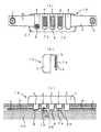
図7(a),(b),(c)で示す生体モニタ装置1Aは、本願発明の第2の実施の形態に係るものである。この生体モニタ装置1Aは、コモン電極6が配された支持部3と電極アーム部4が形成された支持部3との間に、非接触電極7Aが設けられた支持部3が形成されるもので、この非接触電極7Aと生体20との間には非導電部3Aが形成されるものである。この実施の形態では、非接触電極7Aが形成された支持部3は、合成樹脂等の絶縁部材によって形成され、前記非接触電極7Aは、支持部3の生体20とは反対側の側面に形成される。これによって支持部3によって非導電部3Aが構成される。また、非接触電極7Aを生体側側面に形成し、この表面に絶縁部材をコーティングすることによって非導電部3Aを形成しても良いものである。尚、前述した実施の形態と同一の個所及び同一の効果を奏する個所には同一の符号を付してその説明を省略する。
【0028】
【発明の効果】
以上説明したように、この発明によれば、生体モニタ装置を下着等の衣類に簡単に装着することができると共に、生体モニタ装置を装着するだけで、心電図電極を最も適切な位置で生体に接触させることができ、且つ呼吸数・脈拍数を検出する非接触電極を所定の位置に配置することができるため、電極を装着する等のわずらわしい手間が省けるものである。
【0029】
さらに、常時生体モニタ装置の装着が可能であることから、被験者の生活に密着した測定データを検出することができ、また長時間生体をモニタすることができ、且つ定期的にデータの送信ができるため、有益なデータを得ることができるものである。また、緊急時にはそのデータを即時に送信することもできるため、被験者の診療又は治療に非常に有効なデータを検出し送信できるものである。
【図面の簡単な説明】
【図1】本願発明の第1の実施の形態に係る生体モニタ装置の概略を示す図面であり、(a)は正面図、(b)は背面図、(c)は側面図、(d)は平面図を示す。
【図2】生体モニタ装置に内設される電気回路図の概略構成ブロック図である。
【図3】(a)は心電図信号からノイズを除去する状態を示した説明図であり、(b)は心電図信号から筋電図信号を除去する状態を示した説明図である。
【図4】発振周波数を検出する回路の一例を示した説明図である。
【図5】発振周波数波形において呼吸及び心拍の周期を示した説明図である。
【図6】体位検出センサの配置ついて説明した説明図である。
【図7】本願発明の第2の実施の形態に係る生体モニタ装置の概略を示す図面であり、(a)は背面図、(b)は側面図、(c)は平面図を示す。
【符号の説明】
1,1A 生体モニタ装置
2 本体ケース
3 支持部
4 電極アーム部
5 心電図電極
6 コモン電極
7,7A 非接触電極
8 温度検出センサ
10 衣類
20 生体[0001]
[Technical field to which the invention belongs]
This invention can be worn on clothing such as underwear, and can detect biological data such as electrocardiogram, respiratory rate, body temperature, pulse rate, body position detection, biological activity, etc. for a long time, and transmit these data. The present invention relates to a living body monitor device capable of
[0002]
[Prior art]
In Japanese Patent Application Laid-Open No. 2001-299712, the present applicant has disclosed a device that can be attached to an underwear or the like with a mounting tape, a hook, or a pocket, and can monitor an electrocardiogram, respiration, body temperature, posture and activity amount for a long time. This device has a body case, a pair of electrocardiogram electrodes, a capacitance detection unit that detects a respiratory rate and a pulse rate, a temperature sensor that detects body temperature, a sensor that detects body position, and an activity level. And at least an acceleration sensor, and further, a wireless telemeter for transmitting measurement data obtained by these sensors. In particular, the capacitance detection unit has an electrode insulated from a living body, detects a change in capacitance between the living body and the electrode that fluctuates due to movement of the living body based on respiration, pulse, etc., and from this signal The respiratory rate and pulse rate are detected.
[0003]
[Problems to be solved by the invention]
The present invention is to further improve the invention disclosed in the above-mentioned Japanese Patent Application Laid-Open No. 2001-299712, and to provide a living body monitor device that improves the wearability and wearing feeling of the living body monitor device.
[0004]
[Means for Solving the Problems]
Therefore, the present invention comprises at least a contact electrode that contacts the living body, a non-contact electrode that is non-contacting the living body at a predetermined interval, and a common electrode that contacts the living body. An electrocardiogram detection unit for detecting an electrocardiogram signal from the contact electrode; a respiratory pulse detection unit for detecting respiration and a pulse by detecting a change in capacitance generated between the non-contact electrode and a living body; and the electrocardiogram detection unit A signal processing unit that converts and detects the signal detected by the signal and the signal detected by the respiratory pulse detection unit, a storage unit that stores the signal calculated by the signal processing unit, and a signal processing unit In a living body monitor device comprising at least a signal output unit that outputs a signal output and a wireless output unit that transmits a signal output from the signal output unit, A plurality of support portions extending at intervals and supporting the main body case across an end portion of clothing directly attached to the living body, and an electrode arm portion extending from at least one of the support portions; The common electrode is provided in a portion of the at least one support portion that comes into contact with the living body, and the contact electrode is provided in a contact portion with the living body in the vicinity of the end portion of the electrode arm portion. As a result, the contact electrode and the common electrode can be brought into contact with the living body at a predetermined position only by wearing the living body monitoring apparatus with clothes such as underwear.
[0005]
Furthermore, in this invention, it is desirable that the common electrode is formed on a support portion located in the center of the plurality of support portions, and the electrode arm portion is a support portion located on both outermost sides of theplurality of support portions. It is desirable to form each.
[0006]
Furthermore, it is desirable that the distance between the common electrode and the contact electrode is set within a range of 5 cm to 15 cm.
[0007]
In addition, the non-contact electrode is a living body side surface of the main body case, and is preferably provided between the support portions and non-contact with the living body by clothing straddling the support portion. The non-contact electrode is provided in a support portion positioned between a support portion where the common electrode is provided and a support portion where the contact electrode is provided, and a non-conductive portion is provided between the contact electrode and the living body. May be formed.
[0008]
Furthermore, it is desirable that a temperature sensor is provided in a portion of the support portion that comes into contact with one living body. Furthermore, it is desirable that body position detection means for detecting a three-dimensional movement of the living body is formed in the main body case.
[0009]
DETAILED DESCRIPTION OF THE INVENTION
Embodiments of the present invention will be described below with reference to the drawings.
[0010]
1 (a), 1 (b), 1 (c), 1 (d), a living
[0011]
The
[0012]
Further, an
[0013]
The
[0014]
Furthermore, two
[0015]
Further, a
[0016]
Two
[0017]
The
[0018]
In the electrocardiogram detection unit 35, the signal obtained by the
[0019]
As shown in FIG. 4, the
[0020]
The oscillation frequency fluctuation is counted by a counter circuit and detected as a digital signal on which respiration and pulse waves are superimposed, and this signal is digital in the range of 0.5 seconds (2 Hz) to 10 seconds (0.1 Hz). A first digital filter through which a signal passes and a second digital filter through which a digital signal in a range of 1/3 second (3 Hz) to 2 seconds (0.5 Hz) passes are respectively passed through the first digital filter. The digital signal that has passed through can be detected as a respiratory component, and the digital signal that has passed through the second digital filter can be detected as a pulse component.
[0021]
The three
[0022]
[Table 1]
The on / off state of the first, second, and
[0024]
The
[0025]
The analog output signal from the
[0026]
Biological data such as an electrocardiogram, respiratory rate, pulse rate, body temperature, body position, and activity level detected as described above are not shown periodically via the wireless output unit 45 or in the event of an emergency by pressing the
[0027]
A biological monitor apparatus 1A shown in FIGS. 7A, 7B, and 7C is related to the second embodiment of the present invention. This living body monitoring device 1A is configured such that a
[0028]
【The invention's effect】
As described above, according to the present invention, the biological monitor device can be easily attached to clothing such as underwear, and the electrocardiogram electrode is brought into contact with the living body at the most appropriate position only by attaching the biological monitor device. In addition, since the non-contact electrode for detecting the respiratory rate / pulse rate can be arranged at a predetermined position, troublesome work such as wearing an electrode can be saved.
[0029]
Furthermore, since the living body monitor device can always be mounted, measurement data closely related to the life of the subject can be detected, the living body can be monitored for a long time, and data can be transmitted periodically. Therefore, useful data can be obtained. In addition, since the data can be transmitted immediately in an emergency, it is possible to detect and transmit data that is very effective for medical treatment or treatment of the subject.
[Brief description of the drawings]
FIG. 1 is a schematic view of a living body monitor apparatus according to a first embodiment of the present invention, in which (a) is a front view, (b) is a rear view, (c) is a side view, and (d). Shows a plan view.
FIG. 2 is a schematic configuration block diagram of an electric circuit diagram provided in the living body monitor device.
3A is an explanatory diagram showing a state in which noise is removed from an electrocardiogram signal, and FIG. 3B is an explanatory diagram showing a state in which an electromyogram signal is removed from the electrocardiogram signal.
FIG. 4 is an explanatory diagram showing an example of a circuit for detecting an oscillation frequency.
FIG. 5 is an explanatory diagram showing respiratory and heartbeat periods in an oscillation frequency waveform.
FIG. 6 is an explanatory diagram for explaining the arrangement of body posture detection sensors.
FIGS. 7A and 7B are diagrams schematically illustrating a biological monitor apparatus according to a second embodiment of the present invention, in which FIG. 7A is a rear view, FIG. 7B is a side view, and FIG.
[Explanation of symbols]
DESCRIPTION OF
Claims (8)
Translated fromJapanese前記本体ケースから所定の間隔で延出し、前記生体に直接装着する衣類の端部に跨って前記本体ケースを支持する複数の支持部と、該支持部の少なくとも一つから延出する電極アーム部とを具備すると共に、
前記コモン電極は、少なくとも一つの支持部の生体と接触する部分に設けられ、
前記接触電極は、前記電極アーム部の端部近傍の前記生体との接触部分に設けられることを特徴とする生体モニタ装置。At least a contact electrode that contacts the living body, a non-contact electrode that is non-contact with the living body at a predetermined interval, and a common electrode that contacts the living body; An electrocardiogram detection unit that detects a change in capacitance generated between the non-contact electrode and the living body to detect respiration and a pulse, a signal detected by the electrocardiogram detection unit, and A signal processing unit that converts and detects a signal detected by the respiratory pulse detection unit, a storage unit that stores the signal calculated by the signal processing unit, and a signal that outputs the signal calculated by the signal processing unit In a biological monitor device comprising at least an output unit and a wireless output unit that transmits a signal output from the signal output unit,
A plurality of support portions that extend from the main body case at predetermined intervals and support the main body case across an end portion of clothing that is directly attached to the living body, and an electrode arm portion that extends from at least one of the support portions And comprising
The common electrode is provided in a portion that contacts the living body of at least one support portion,
The living body monitor apparatus, wherein the contact electrode is provided in a contact portion with the living body in the vicinity of an end portion of the electrode arm section.
Priority Applications (1)
| Application Number | Priority Date | Filing Date | Title |
|---|---|---|---|
| JP2002083013AJP4131372B2 (en) | 2002-03-25 | 2002-03-25 | Biological monitor device |
Applications Claiming Priority (1)
| Application Number | Priority Date | Filing Date | Title |
|---|---|---|---|
| JP2002083013AJP4131372B2 (en) | 2002-03-25 | 2002-03-25 | Biological monitor device |
Publications (2)
| Publication Number | Publication Date |
|---|---|
| JP2003275185A JP2003275185A (en) | 2003-09-30 |
| JP4131372B2true JP4131372B2 (en) | 2008-08-13 |
Family
ID=29206815
Family Applications (1)
| Application Number | Title | Priority Date | Filing Date |
|---|---|---|---|
| JP2002083013AExpired - Fee RelatedJP4131372B2 (en) | 2002-03-25 | 2002-03-25 | Biological monitor device |
Country Status (1)
| Country | Link |
|---|---|
| JP (1) | JP4131372B2 (en) |
Families Citing this family (24)
| Publication number | Priority date | Publication date | Assignee | Title |
|---|---|---|---|---|
| DE102004058781A1 (en)* | 2004-12-07 | 2006-06-08 | Dräger Safety AG & Co. KGaA | Occupational safety product with contactless measuring electrodes |
| US7167737B2 (en)* | 2005-01-03 | 2007-01-23 | Shimano Inc. | Heart rate monitoring unit |
| US8260405B2 (en)* | 2005-12-19 | 2012-09-04 | Koninklijke Philips Electronics N.V. | Monitoring apparatus for monitoring a user's heart rate and/or heart rate variation; wristwatch comprising such a monitoring apparatus |
| CN101108125B (en)* | 2007-08-02 | 2010-06-16 | 无锡微感科技有限公司 | Dynamic monitoring system of body sign |
| US9011327B2 (en)* | 2007-12-20 | 2015-04-21 | Koninklijke Philips N.V. | Capacitive sensing and communicating |
| WO2011137566A1 (en) | 2010-05-07 | 2011-11-10 | Yang Changming | Method and system for generating physiological signals with fabric capacitive sensors |
| JP5580801B2 (en)* | 2011-10-13 | 2014-08-27 | セイコーインスツル株式会社 | Biological information detection device |
| JP5441977B2 (en)* | 2011-10-13 | 2014-03-12 | セイコーインスツル株式会社 | Biological information detection device |
| AU2013322868B2 (en)* | 2012-09-26 | 2017-03-16 | Laerdal Medical As | Pulse meter for new-borns |
| KR102164705B1 (en) | 2013-06-17 | 2020-10-12 | 삼성전자주식회사 | Method and device to measure bio signal using connectable capacitive coupling active electrode |
| JP6215721B2 (en)* | 2014-01-28 | 2017-10-18 | 日本電信電話株式会社 | Wearable electrode and bioelectric signal measurement system |
| KR102302876B1 (en) | 2014-06-23 | 2021-09-17 | 삼성전자주식회사 | Bioelectrode and biosignal processing apparatus and method using the same |
| JP2016063854A (en)* | 2014-09-22 | 2016-04-28 | フクダ電子株式会社 | Electrophysiological inspection system |
| KR101697078B1 (en)* | 2015-02-04 | 2017-01-17 | 이태규 | Digital bio pach |
| JP6589352B2 (en)* | 2015-04-17 | 2019-10-16 | 富士通株式会社 | Biological information measuring device, sensor unit, and biological information measuring system |
| JP2018038597A (en)* | 2016-09-07 | 2018-03-15 | 国立大学法人神戸大学 | Biological information measuring probe and biological information measuring apparatus |
| AU2018322998B2 (en)* | 2017-09-01 | 2023-08-03 | Societe Des Produits Nestle S.A. | Heart rate detection device and related systems and methods |
| RU2729430C1 (en)* | 2019-05-13 | 2020-08-06 | федеральное государственное бюджетное образовательное учреждение высшего образования "Московский политехнический университет" (Московский Политех) | Hardware-software system for life indicators monitoring |
| JP6718183B1 (en)* | 2019-06-24 | 2020-07-08 | 株式会社アイ・メデックス | Biological electrode with electronic circuit board |
| CN110881970B (en)* | 2019-11-28 | 2023-06-02 | 深圳市善行医疗科技有限公司 | Electrocardiogram measuring method, electrocardiogram measuring device, electronic equipment and storage medium |
| TWI725839B (en)* | 2020-05-05 | 2021-04-21 | 穎翔科技股份有限公司 | Physiological sensing system |
| KR20230019599A (en)* | 2021-08-02 | 2023-02-09 | 삼성전자주식회사 | Sensor structure and electronic device including same |
| CN115337001A (en)* | 2022-09-13 | 2022-11-15 | 苏州众智初心健康科技有限公司 | Respiration detection control method, respiration detection device, and storage medium |
| KR102775897B1 (en)* | 2023-11-16 | 2025-03-06 | 주식회사 에이티센스 | Respiratory sensing device and method of using the respiratory sensing device |
- 2002
- 2002-03-25JPJP2002083013Apatent/JP4131372B2/ennot_activeExpired - Fee Related
Also Published As
| Publication number | Publication date |
|---|---|
| JP2003275185A (en) | 2003-09-30 |
Similar Documents
| Publication | Publication Date | Title |
|---|---|---|
| JP4131372B2 (en) | Biological monitor device | |
| JP4705358B2 (en) | ECG measurement apparatus and ECG measurement system | |
| JP4460306B2 (en) | Wearable monitor system and method for manufacturing wearable monitor system | |
| JP3932726B2 (en) | Biological monitor device | |
| RU2444986C1 (en) | Wearable monitor with automatic transmission of diagnosis via communication channel in case of critical situation arises | |
| JP2011507569A (en) | Monitoring apparatus and method | |
| Sardini et al. | Instrumented wearable belt for wireless health monitoring | |
| JP2008086390A (en) | Biological information detection device | |
| WO2009014309A1 (en) | Garment for measuring physiological signal and system for processing physiological signal | |
| JP2000000214A (en) | Sleeping monitor device | |
| WO2019213587A1 (en) | Device and methods for deriving a respiration rate from multiple biometric sources | |
| CN112384142A (en) | Electrocardiogram measuring system and electrocardio emitter | |
| US20110071412A1 (en) | Belt Type Bio-Signal Detecting Device | |
| WO2017190965A1 (en) | A method and apparatus for verifying whether to change a determined wearing status of a device | |
| US10582868B1 (en) | Leadless ECG monitoring via fusion of DSP and analog signal conditioning techniques | |
| WO2018044170A1 (en) | Sleep trainer with heart rate measurement band | |
| EP2113195B1 (en) | Accessory for performance-monitoring device | |
| CN100415160C (en) | System for bioelectrical interaction with an individual using simplified electrode fixation | |
| JP2001299712A (en) | Long-time biological monitor | |
| JP2015020050A (en) | Electrocardiograph | |
| KR101763469B1 (en) | Matrix for detecting wearable bio-signal | |
| JP4081755B2 (en) | Electrocardiograph | |
| CN211299920U (en) | Sleep monitoring vest and system | |
| CN221309321U (en) | Wearable defibrillation device | |
| CN216932129U (en) | Intelligent wrist strap device |
Legal Events
| Date | Code | Title | Description |
|---|---|---|---|
| A521 | Request for written amendment filed | Free format text:JAPANESE INTERMEDIATE CODE: A821 Effective date:20020325 | |
| A621 | Written request for application examination | Free format text:JAPANESE INTERMEDIATE CODE: A621 Effective date:20050304 | |
| A977 | Report on retrieval | Free format text:JAPANESE INTERMEDIATE CODE: A971007 Effective date:20061027 | |
| A131 | Notification of reasons for refusal | Free format text:JAPANESE INTERMEDIATE CODE: A131 Effective date:20080205 | |
| A521 | Request for written amendment filed | Free format text:JAPANESE INTERMEDIATE CODE: A523 Effective date:20080228 | |
| A521 | Request for written amendment filed | Free format text:JAPANESE INTERMEDIATE CODE: A523 Effective date:20080228 | |
| TRDD | Decision of grant or rejection written | ||
| A01 | Written decision to grant a patent or to grant a registration (utility model) | Free format text:JAPANESE INTERMEDIATE CODE: A01 Effective date:20080422 | |
| A01 | Written decision to grant a patent or to grant a registration (utility model) | Free format text:JAPANESE INTERMEDIATE CODE: A01 | |
| A61 | First payment of annual fees (during grant procedure) | Free format text:JAPANESE INTERMEDIATE CODE: A61 Effective date:20080515 | |
| FPAY | Renewal fee payment (event date is renewal date of database) | Free format text:PAYMENT UNTIL: 20110606 Year of fee payment:3 | |
| R150 | Certificate of patent or registration of utility model | Free format text:JAPANESE INTERMEDIATE CODE: R150 | |
| FPAY | Renewal fee payment (event date is renewal date of database) | Free format text:PAYMENT UNTIL: 20130606 Year of fee payment:5 | |
| R250 | Receipt of annual fees | Free format text:JAPANESE INTERMEDIATE CODE: R250 | |
| LAPS | Cancellation because of no payment of annual fees |