JP4128433B2 - Control method of refrigeration cycle - Google Patents
Control method of refrigeration cycleDownload PDFInfo
- Publication number
- JP4128433B2 JP4128433B2JP2002345952AJP2002345952AJP4128433B2JP 4128433 B2JP4128433 B2JP 4128433B2JP 2002345952 AJP2002345952 AJP 2002345952AJP 2002345952 AJP2002345952 AJP 2002345952AJP 4128433 B2JP4128433 B2JP 4128433B2
- Authority
- JP
- Japan
- Prior art keywords
- compressor
- pressure
- differential pressure
- flow rate
- orifice
- Prior art date
- Legal status (The legal status is an assumption and is not a legal conclusion. Google has not performed a legal analysis and makes no representation as to the accuracy of the status listed.)
- Expired - Fee Related
Links
- 238000005057refrigerationMethods0.000titleclaimsdescription56
- 238000000034methodMethods0.000titleclaimsdescription22
- 239000003507refrigerantSubstances0.000claimsdescription83
- 238000006073displacement reactionMethods0.000claimsdescription46
- 238000005259measurementMethods0.000claims1
- 238000010586diagramMethods0.000description6
- 230000007423decreaseEffects0.000description5
- 230000001133accelerationEffects0.000description4
- 238000004891communicationMethods0.000description3
- 238000011144upstream manufacturingMethods0.000description3
- CURLTUGMZLYLDI-UHFFFAOYSA-NCarbon dioxideChemical compoundO=C=OCURLTUGMZLYLDI-UHFFFAOYSA-N0.000description2
- XEEYBQQBJWHFJM-UHFFFAOYSA-NIronChemical group[Fe]XEEYBQQBJWHFJM-UHFFFAOYSA-N0.000description2
- 229910021076Pd—PdInorganic materials0.000description2
- 230000009194climbingEffects0.000description2
- 239000002826coolantSubstances0.000description2
- 238000001816coolingMethods0.000description2
- 238000012544monitoring processMethods0.000description2
- LVGUZGTVOIAKKC-UHFFFAOYSA-N1,1,1,2-tetrafluoroethaneChemical compoundFCC(F)(F)FLVGUZGTVOIAKKC-UHFFFAOYSA-N0.000description1
- 229910002092carbon dioxideInorganic materials0.000description1
- 239000001569carbon dioxideSubstances0.000description1
- 230000006835compressionEffects0.000description1
- 238000007906compressionMethods0.000description1
- 238000001514detection methodMethods0.000description1
- 230000000694effectsEffects0.000description1
- 239000000446fuelSubstances0.000description1
Images


Landscapes
- Compressors, Vaccum Pumps And Other Relevant Systems (AREA)
- Control Of Positive-Displacement Pumps (AREA)
- Air-Conditioning For Vehicles (AREA)
Description
Translated fromJapanese【0001】
【発明の属する技術分野】
本発明は冷凍サイクルの制御方法に関し、特に膨張装置として弁開度の調整機能を持たないオリフィスチューブを用いた冷凍サイクルからなる自動車用空調装置にて容量可変型圧縮機を駆動するエンジンに対してできるだけ負荷が少なくかつ高精度な制御が可能な冷凍サイクルの制御方法に関する。
【0002】
【従来の技術】
自動車用空調装置においては、圧縮機がエンジンによって駆動されるため、運転状態がエンジンの運転状態によって大きく影響される。逆に、エンジンは、自動車用空調装置が負荷になっており、自動車用空調装置を駆動するための余分なエネルギを必要とする。
【0003】
エンジンの出力は、その負荷である自動車用空調装置の運転状態に応じて制御する必要がある。たとえば自動車用空調装置が運転中は、圧縮機の駆動トルクを考慮し、その駆動トルクを余分に発生するようにエンジン出力トルクが制御されている。圧縮機の駆動トルクは、あらかじめ設定されていて、自動車用空調装置が運転されるときは、そのあらかじめ設定された固定値だけ余分に駆動トルクを発生するように制御している。
【0004】
あらかじめ設定された駆動トルクは、実際の駆動トルクと大きく相違することがあるため、エンジン出力トルクも必要なトルクからずれて制御されることになる。そのため、たとえば特許文献1に記載の技術では、容量可変型圧縮機の吐出容量を外部から電気制御するための圧縮機制御信号に基づいて、容量可変型圧縮機の駆動トルクを推定し、これを上乗せしてエンジン出力トルクを制御するようにしている。
【0005】
このような制御は、膨張装置が外部から与えられる信号によって弁開度が自由に設定できる圧力制御弁を使用した構成の冷凍サイクルについて述べているが、膨張装置として弁開度の調整機能を持たないオリフィスチューブを用いた冷凍サイクル(たとえば特許文献2。)においても同じことが言える。
【0006】
すなわち、自動車用空調装置の運転中に自動車が発進または加速走行しようとしたときには、容量可変型圧縮機の駆動トルクを制御することにより、燃料消費を大きく増やすことなく発進または加速に必要なエンジン出力トルクを確保することができるのである。
【0007】
【特許文献1】
特開2001−180261号公報(段落番号〔0006〕,図2)
【特許文献2】
特開昭56−7959号公報(図1)
【0008】
【発明が解決しようとする課題】
しかしながら、従来の冷凍サイクルの制御において、エンジン出力トルクの制御に必要な容量可変型圧縮機の駆動トルクについては、冷媒循環回路に設定された2つの圧力監視点間の差圧に容量可変型圧縮機の吐出容量が反映されていることから、2つの圧力監視点間の差圧を設定するための圧縮機制御信号から容量可変型圧縮機の吐出容量つまりはその駆動トルクを推定しているが、実際には、その圧縮機制御信号からだけでは、容量可変型圧縮機の駆動トルクを正確に推定することは難しいという問題点があった。
【0009】
本発明はこのような点に鑑みてなされたものであり、容量可変型圧縮機の駆動トルクを正確に推定し、必要とするエンジン出力トルクに応じてエンジン負荷である容量可変型圧縮機の駆動トルクを制御することができるような、膨張装置にオリフィス部を用いた冷凍サイクルの制御方法を提供することを目的とする。
【0010】
【課題を解決するための手段】
本発明では上記問題を解決するために、容量可変型圧縮機が冷媒を一定の冷媒流量で吐出するように制御される容量制御弁を有し、膨張装置にオリフィス部を用いた冷凍サイクルの制御方法において、前記容量可変型圧縮機の吐出容量を外部から制御するための前記冷媒流量を表す前記容量制御弁の圧縮機制御信号から前記オリフィス部の差圧−流量特性に基づいて前記オリフィス部の高圧側圧力と低圧側圧力との差圧を推定するとともに、推定した前記差圧と前記圧縮機制御信号による前記冷媒流量と前記容量可変型圧縮機を駆動するエンジンの回転数とから前記容量可変型圧縮機の駆動トルクを推定し、自動車が発進または急加速時には、推定した前記容量可変型圧縮機の駆動トルクがゼロに、前記自動車の加速または登坂走行時には、前記容量可変型圧縮機の駆動トルクが小さくなるように前記圧縮機制御信号を制御することを特徴とする冷凍サイクルの制御方法が提供される。
【0011】
このような冷凍サイクルの制御方法によれば、圧縮機の駆動トルク、すなわち冷凍サイクルのエネルギ状態を、容量可変型圧縮機の吐出容量の制御に使われる圧縮機制御信号をもとに推定し、これをもとにして自動車の走行状態に応じた冷凍サイクルの制御を行うようにしている。これにより、冷凍サイクルのエネルギ状態は、実際に容量可変型圧縮機を制御している圧縮機制御信号の値から算出していることにより、正確に推定することができるため、冷凍サイクルをよりきめ細かく制御することが可能になる。
【0012】
【発明の実施の形態】
まず、本発明の原理から先に説明する。
冷凍サイクルの冷力Q、すなわちエネルギは、冷凍サイクル内の冷媒の高圧側圧力と低圧側圧力との差圧ΔPと冷媒流量Gfとの積に比例し、
【0013】
【数1】
Q∝Gf*△P ・・・(1)
で表すことができる。一方、冷凍サイクルを動かすのに必要なエンジンのエネルギは、Nをエンジンの回転数、Tを駆動トルクとすると、
【0014】
【数2】
Q∝N*T ・・・(2)
で表される。これらの式から、
【0015】
【数3】
Q∝N*T∝Gf*△P ・・・(3)
が得られる。この式から、冷凍サイクル内の冷媒高圧側圧力と低圧側圧力との差圧ΔPと冷媒流量Gfと回転数Nとが分かれば、容量可変型圧縮機の駆動トルクが分かることになる。ここで、差圧ΔPは、容量可変型圧縮機の吐出圧力Pdと吸入圧力Psとの差、あるいは、膨張装置の入口圧力と出口圧力との差であり、容量可変型圧縮機あるいは膨張装置の差圧を外部から一定の差圧に制御する容量可変型圧縮機用の容量制御弁の電気信号の関数になっている。一方、冷媒流量Gfは、容量可変型圧縮機あるいは膨張装置において冷媒が通過するオリフィスの面積およびその前後の差圧から求められる値で、容量可変型圧縮機を外部から一定の容量に制御する容量可変型圧縮機用の容量制御弁の電気信号の関数になっている。つまり、差圧ΔPまたは冷媒流量Gfは、外部からの電気信号によって容量制御弁のコイルへ供給される電流iによって決められるので、これらの電流値を直接検出することによって冷凍サイクルのエネルギを正確に求めることができる。
【0016】
また、冷凍サイクルを動かすのに必要なエンジンのエネルギの式(3)からは、エンジンの回転数Nが分かっているので、式(3)により駆動トルクTが分かる。しかも、冷凍サイクルのエネルギを求めるパラメータが正確に検出できることから駆動トルクTをより正確に求めることができる。
【0017】
これにより、差圧ΔPまたは冷媒流量Gfを電気信号によって制御することにより、冷凍サイクルのエネルギを自由に制御できるだけでなく、駆動トルクTも自由に制御できることになる。
【0018】
以下、本発明の実施の形態を図面を参照して詳細に説明する。
図1は冷凍システムの原理的な構成を示すシステム図である。
この冷凍システムは、冷媒を圧縮する容量可変型圧縮機1と、圧縮された冷媒を凝縮する凝縮器2と、凝縮された冷媒を段熱膨張させる膨張装置3と、膨張された冷媒を蒸発させる蒸発器4とを備えている。
【0019】
容量可変型圧縮機1は、一定流量の冷媒を吐出する流量制御式、または冷媒入口と出口との差圧を一定に制御する差圧制御式のものが用いられる。膨張装置3は、固定オリフィスを有するオリフィスチューブからなる。
【0020】
容量可変型圧縮機1は、その吐出室から吐出される吐出圧力Pdの冷媒を直接凝縮器2に供給するとともに、その一部を容量制御弁5で圧力Pcにしてクランク室に供給するよう構成され、その容量制御弁5は、駆動回路6に接続されている。また、蒸発器4から戻ってきた吸入圧力Psの冷媒は、吸入室に供給するよう構成され、さらに、吸入室とクランク室との間には、オリフィス7が設けられている。
【0021】
容量制御弁5は、容量可変型圧縮機1から吐出される冷媒を駆動回路6によって与えられた制御信号により決まる一定の流量または一定の差圧で吐出するように制御する。
【0022】
次に、容量可変型圧縮機1が流量制御の場合または差圧制御の場合のおのおのについて説明する。
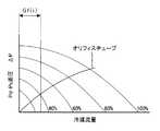
図2は流量制御の容量可変型圧縮機の場合の冷凍システムの差圧−流量特性を示す図である。
【0023】
この特性において、縦軸は容量可変型圧縮機1の吐出圧力Pdと吸入圧力Psとの差圧を示し、横軸は冷凍サイクルを流れる冷媒の流量を示している。ここで、曲線は、容量可変型圧縮機1がある回転数で回転しているときの圧縮機可変容量率を示しており、原点から最も遠い曲線は圧縮機可変容量率が100%、つまり、容量可変型圧縮機1が最大で運転しているときを示している。
【0024】
容量可変型圧縮機1は流量制御式なので、吐出される冷媒流量Gf(i)は駆動回路6によって与えられる容量制御弁5の制御信号の電流値iによって決められる。また、膨張装置3における差圧ΔPに関しては、オリフィスの大きさによって傾きが決められる。したがって、この冷凍システムでは、電流値iによって容量可変型圧縮機1の冷媒流量Gf(i)が分かるので、そのときの差圧ΔPおよび可変容量率を知ることができる。
【0025】
この可変容量率は、自動車が発進、加速または登坂走行するときには、エンジンは、その出力トルクを余分に必要としているが、そのときの容量可変型圧縮機1の駆動トルクは、冷凍サイクルの冷力であるエネルギとエンジンの回転数とから分かるため、エンジンが余分に必要としている出力トルク分だけ、冷凍サイクルのエネルギを減らすように容量可変型圧縮機1の冷媒流量Gf(i)を制御することができる。なお、冷凍サイクルが運転中のエネルギから、エンジンの回転数に対応する駆動トルクが分かるので、その駆動トルクを、たとえば自動車のアイドリング時のエンジン出力トルクの制御に利用することができる。すなわち、その駆動トルクの値を使い、その駆動トルク分を上乗せしてエンジン出力トルクを制御し、これによってエンジンの不安定動作、さらには停止といった不具合を防止することができる。
【0026】
次に、この冷凍システムを構成する容量可変型圧縮機1の具体例について説明する。
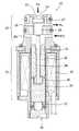
図3は流量制御式の容量可変型圧縮機の一構成例を示す断面図、図4は図3の容量可変型圧縮機に用いられる電磁差圧弁の詳細を示す断面図である。
【0027】
この容量可変型圧縮機は、気密に形成されたクランク室10を有し、中には回転自在に支持された回転軸11を有している。この回転軸11の一端は、図示しない軸封装置を介してクランク室10の外まで延びていてエンジンの出力軸から駆動力が伝達されるプーリ12が固定されている。回転軸11には、揺動板13が傾斜角可変に設けられている。回転軸11の軸線の回りには、複数(図示の例では1つ)のシリンダ14が配置されている。各シリンダ14には、揺動板13の回転運動を往復運動に変換するピストン15が配置されている。各シリンダ14は、それぞれ吸入用リリーフ弁16および吐出用リリーフ弁17を介して吸入室および吐出室に接続されている。各シリンダ14の吸入室は、相互に連通して1つの部屋になっており、蒸発器に接続される。また、各シリンダ14の吐出室も、相互に連通して1つの部屋になっており、吐出側冷媒流路18を介して凝縮器に接続される。
【0028】
吐出室の吐出側冷媒流路18には、流路面積が固定のオリフィス19が設けられている。吐出室からクランク室10へ通じる流路には、容量制御の電磁差圧弁20が設けられ、クランク室10から吸入室へ通じる流路には、固定オリフィス21が設けられている。電磁差圧弁20は、オリフィス19の上流側および下流側に発生する差圧(Pd−Pd’)を受けるよう構成されている。
【0029】
電磁差圧弁20は、本出願人による特願2001−170434号明細書にて提案したもので、図4に示したように、圧力感知部を兼ねた弁部22と、ソレノイド部23とから構成されている。
【0030】
弁部22は、吐出圧力Pdを導入するポート24と、導入された吐出圧力Pdをクランク室圧力Pcに制御して出力する弁体25と、クランク室圧力Pcを出力するポート26と、弁体25を開く方向へ付勢するスプリング27と、この電磁差圧弁20の中央軸線位置にて弁体25と一体となって進退可能に設けられ、ポート24とほぼ同じ径を有する感圧ピストン28と、この感圧ピストン28の弁体25と反対側にオリフィス19の下流側の圧力Pd’を導入するポート29とを有している。
【0031】
ソレノイド部23は、円筒状の中空部を有する電磁コイル30が設けられ、その円筒状の中空部にはスリーブ31が設けられている。そのスリーブ31の一端には、固定鉄芯をなすコア32が固定され、スリーブ31の中には、可動鉄芯をなすプランジャ33が軸線方向に移動可能に遊挿配置されている。コア32の軸線位置にはシャフト34が貫通配置され、その一端は感圧ピストン28に、他端はプランジャ33に当接されている。スリーブ31の他端には、アジャストねじ35が螺着されている。そして、コア32とプランジャ33との間には、スプリング36が配置され、プランジャ33とアジャストねじ35との間には、スプリング37が配置されている。
【0032】
以上の構成の容量可変型圧縮機において、エンジンがある一定の回転数で駆動されているとき、蒸発器からの冷媒が吸入室より流量Qsで吸引され、吐出室から流量Qdで吐出される。このとき、電磁差圧弁20は、吐出室の冷媒の吐出圧力Pdを弁部22を介してクランク室10へ導入する。これにより、容量可変型圧縮機の吐出容量は、クランク室10内の圧力Pcに応じた容量に制御される。クランク室10の圧力Pcは、固定オリフィス21を介して引き抜かれ、吸入室に戻される。
【0033】
このとき、ソレノイド部23の電磁コイル30には、外部条件に応じた電磁差圧弁20の差圧に対応する電流信号が供給される。
したがって、電磁差圧弁20は、オリフィス19の前後に発生する差圧を弁部22の弁体25および感圧ピストン28で感知し、その差圧が設定された所定値になるよう弁部22の弁体25を制御して、吐出側冷媒流路18を流れる冷媒流量を一定の流量Qdに保持するように制御する。
【0034】
すなわち、エンジンの回転数が上昇すると、吐出圧力Pdが上昇し、それによって、吐出される冷媒の流量Qdが増加しようとする。すると、吐出圧力Pdが高くなるため、弁部22の弁体25および感圧ピストン28はソレノイド部23の側に移動し、弁体25はスプリング27の付勢力によって弁部22の開度を開く方向に移動して、クランク室10へ導入する冷媒流量を増加させる。クランク室10内の圧力Pcが上昇することにより、容量可変型圧縮機を最少運転側に制御し、吐出される冷媒の流量を減らすようにする。
【0035】
逆に、エンジンの回転数が低下した場合は、吐出される冷媒の流量Qdが減少しようとして吐出圧力Pdが低くなると、弁部22の弁体25および感圧ピストン28は図の上側に移動し、弁体25は閉弁方向に移動してクランク室10へ導入する冷媒流量を減らすように制御する。これにより、クランク室10内の圧力Pcが減少し、容量可変型圧縮機を最大運転側に制御し、吐出される冷媒の流量を増やすようにする。
【0036】
この結果、エンジンの回転数が変動しても、電磁差圧弁20はオリフィス19の前後差圧を一定にするようにクランク室10へ導入する冷媒流量を制御する。したがって、オリフィス19が固定でその前後差圧が一定に制御されるため、容量可変型圧縮機から吐出される冷媒の流量Qdは一定の流量に制御されることになる。
【0037】
ここで、電磁差圧弁20に供給される制御信号は、オリフィス19の前後差圧を表しており、オリフィス19の流路面積は固定であるから、制御信号を直接測定することにより、そのときの流量Gfを正確に知ることができる。この流量Gfは膨張装置3を通過する流量でもあり、膨張装置3のオリフィスチューブの流路面積は固定であることから、冷凍サイクル内の高圧側圧力と低圧側圧力との差圧ΔPを知ることができる。したがって、流量Gfおよび差圧ΔPが分かり、そのときのエンジンの回転数Nは分かっているので、駆動トルクTを求めることができるのである。
【0038】
このようにして求められた容量可変型圧縮機の駆動トルクTは、自動車が発進または急加速時には、ゼロに、自動車の加速または登坂走行時には、小さくなるように制御信号を制御する。具体的には、オリフィス19の前後差圧を表す制御信号を、急加速時に差圧がゼロになるよう制御し、登坂走行時に差圧が小さくなるよう制御する。このように、自動車の走行状態に応じて容量可変型圧縮機の駆動トルクTを変えるようにしたことで、自動車用空調装置が運転中にもかかわらず、自動車の走行性能を改善することができる。
【0039】
図5は流量制御式の容量可変型圧縮機の別の構成例を示す断面図、図6は図5の容量可変型圧縮機に用いられる電磁比例式流量制御弁の詳細を示す断面図、図7は図5の容量可変型圧縮機に用いられる定差圧弁の詳細を示す断面図である。なお、図5ないし図7において、図3および図4に示した構成要素と同じまたは同等の要素については同じ符号を付して、その詳細な説明は省略する。
【0040】
この流量制御式の容量可変型圧縮機は、本出願人による特願2001−170435号明細書にて提案したものであり、吐出室から凝縮器へ向かう吐出側冷媒流路18に電磁比例式流量制御弁40を設け、流路面積を外部信号によって比例的に変化させることができる可変オリフィスを構成している。また、吐出室は、定差圧弁41を介してクランク室10に接続され、クランク室10は固定の固定オリフィス21を介して吸入室に接続されている。定差圧弁41は、吐出室の吐出圧力Pdと電磁比例式流量制御弁40を通ってきた吐出側冷媒流路18の圧力Pd’とを導入し、電磁比例式流量制御弁40の前後に発生する差圧が一定になるように、吐出室からクランク室10、さらにはクランク室10から固定オリフィス21を介して吸入室へ流れる冷媒を制御する弁である。
【0041】
電磁比例式流量制御弁40は、図6に示したように、弁部42およびソレノイド部43から構成されている。弁部42は、吐出室の吐出圧力Pdを導入するポート44と、この弁部42にて減圧された圧力Pd’を吐出側冷媒流路18へ導出するポート45とを有し、これらを連通する流路には、弁座46が形成され、この弁座46の上流側にボール形状の弁体47が弁座46に対向して配置されている。ポート44の開口端にはアジャストねじ48が螺着されており、弁体47とアジャストねじ48との間には、弁体47を閉じる方向に付勢するスプリング49が配置されている。また、弁体47は弁孔を介して軸線方向に延びるシャフト50の一端に当接しており、このシャフト50の他端は、軸線方向に進退自在に配置されたピストン51に固定されている。このピストン51は弁孔とほぼ同じ径を有し、弁体47より下流側の圧力Pd’が軸線両方向に対して等しくかかるようにして弁体47の制御に圧力Pd’が影響しないようにしている。また、弁体47の上流側空間とピストン51のソレノイド部側空間との間には、連通路52が設けられており、ピストン51の背圧側に吐出圧力Pdを導入して、弁体47にかかる吐出圧力Pdをキャンセルするようにしている。
【0042】
ソレノイド部43は、電磁コイル53、コア54、プランジャ55、シャフト56を有している。シャフト56の両端は、ガイド57,58によって支持されている。シャフト56のほぼ中央部には、Eリング59が嵌着されており、プランジャ55がコア54に吸着するよう移動したとき、シャフト56も一緒に移動するようにしている。これにより、プランジャ55が図の上方へ移動すると、シャフト56が図の上端に当接されているピストン51を押し、弁体47を開く方向に作用する。その移動量は、電磁コイル53に供給する電流値に比例する。したがって、この電磁比例式流量制御弁40を通る冷媒の流路面積は、電磁コイル53に供給される制御電流の値によって決めることができる。
【0043】
定差圧弁41は、図7に示したように、吐出室の吐出圧力Pdを導入するポート60と、この定差圧弁41で制御された圧力Pcをクランク室10へ導入するポート61と、電磁比例式流量制御弁40によって減圧された圧力Pd’を導入するポート62とを有している。
【0044】
ポート60とポート61とを連通する流路には、弁座63が形成され、この弁座63の下流側に弁体64が弁座63に対向して配置されている。この弁体64には、フランジが設けられていて、弁座63との間に弁体64を開く方向へ付勢するスプリング65が配置されている。
【0045】
弁体64と同軸上には、軸線方向に進退自在に配置されて両面にポート61からの吐出圧力Pdとポート62からの圧力Pd’とを受ける感圧ピストン66が設けられており、一体に動くよう弁体64に固定されている。
【0046】
感圧ピストン66の図の下方には、スプリング荷重調整用のアジャストねじ67が設けられ、感圧ピストン66とアジャストねじ67との間には、弁体64を閉じる方向に感圧ピストン66を付勢するスプリング68が配置されている。
【0047】
以上の構成の容量可変型圧縮機においては、電磁比例式流量制御弁40が、所定の制御電流の供給を受けて、凝縮器に連通する吐出側冷媒流路18を絞り、所定の大きさのオリフィスを形成し、流量Qdにより所定の差圧(Pd−Pd’)を発生させるようにしている。また、定差圧弁41は、感圧ピストン66が所定の差圧(Pd>Pd’)を受け、それによって発生する図の下向きの力とスプリング65,68の荷重とが釣り合う位置に弁体64が静止し、弁開度が制御されている。したがって、制御電流によって決まる電磁比例式流量制御弁40の前後差圧を定差圧弁41が感知し、定差圧弁41は、その差圧があらかじめ設定された所定値(すなわち、一定の流量Qd)になるよう弁開度を調整して、クランク室10に導入される冷媒の流量を制御し、これによって定流量式の容量可変型圧縮機を構成している。
【0048】
ここで、電磁比例式流量制御弁40に供給される制御信号は、吐出側のオリフィスの流路面積を表しており、その前後の差圧は定差圧弁41によって一定に維持されているので、制御信号を直接測定することにより、そのときの流量Gfを正確に知ることができる。この流量Gfは膨張装置3を通過する流量でもあり、膨張装置3のオリフィスチューブの流路面積は固定であることから、冷凍サイクル内の高圧側圧力と低圧側圧力との差圧ΔPを知ることができる。したがって、流量Gfおよび差圧ΔPが分かり、そのときのエンジンの回転数Nは分かっているので、駆動トルクTを求めることができるのである。
【0049】
このようにして求められた容量可変型圧縮機の駆動トルクTは、自動車が発進または急加速時には、ゼロに、自動車の加速または登坂走行時には、小さくなるように制御信号を制御する。具体的には、可変オリフィスの流路面積を表す制御信号を、急加速時に可変オリフィスの流路面積がゼロ(全閉)になるよう制御し、登坂走行時に可変オリフィスの流路面積が小さくなるよう制御する。このように、自動車の走行状態に応じて容量可変型圧縮機の駆動トルクTを変えるようにしたことで、エンジンの駆動トルクを大きくしたいときに容量可変型圧縮機の駆動トルクTが小さくなって、自動車の走行性能を改善することができる。
【0050】
次に、差圧制御の容量可変型圧縮機1の場合について説明する。
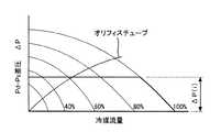
図8は差圧制御の容量可変型圧縮機の場合の冷凍システムの差圧−流量特性を示す図である。
【0051】
この特性において、縦軸は容量可変型圧縮機1の吐出圧力Pdと吸入圧力Psとの差圧を示し、横軸は冷凍サイクルを流れる冷媒の流量を示している。
容量可変型圧縮機1は差圧制御式なので、その吐出圧力Pdと吸入圧力Psとの差圧ΔP(i)は駆動回路6によって与えられる制御信号の電流値iによって決められる。また、膨張装置3における差圧ΔPに関しては、オリフィスの大きさによって傾きが決められる。したがって、この冷凍システムでは、電流値iによって容量可変型圧縮機1の吐出圧力Pdと吸入圧力Psとの差圧ΔPが分かるので、そのときの冷媒流量Gf(i)および可変容量率を知ることができる。
【0052】
次に、この冷凍システムを構成する差圧制御の容量可変型圧縮機1の具体例について説明する。
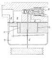
図9は差圧制御式の容量可変型圧縮機の一構成例を示す断面図、図10は図9の容量可変型圧縮機に用いられる容量制御弁の詳細を示す断面図である。なお、この図9において、図3に示した構成要素と同じまたは同等の要素については同じ符号を付して、その詳細な説明は省略する。
【0053】
この容量可変型圧縮機は、本出願人による特願2002−86084号明細書にて提案したもので、吐出室からクランク室10へ向かう冷媒流路の途中にPd−Ps差圧制御の容量制御弁70が設けられ、吐出室とクランク室10との間、およびクランク室10と吸入室との間には、それぞれ固定オリフィス71,21が設けられている。
【0054】
この容量制御弁70は、図10に示したように、吐出室の吐出圧力Pdを受けてクランク室10に圧力Pcを導入する弁体72を有し、この弁体72には感圧ピストン73が一体に形成されている。感圧ピストン73の図の上端は、通路74を介してクランク室10の圧力Pcを受けるよう構成されている。弁体72は、その弁座75から離れる方向にスプリング76によって付勢されている。
【0055】
弁体72とソレノイド部との間には、径の異なる2つのピストンロッド77,78が軸線方向に進退自在に配置されている。その上側のピストンロッド77は、弁座75の直径と同じ直径を有し、下側のピストンロッド78は、弁体72と一体に形成された感圧ピストン73と同じ直径を有している。これらのピストンロッド77,78の連結部は、縮径されていて、吸入室に連通して吸入圧力Psを受ける空間を構成している。ピストンロッド78の図の下端は、通路79,80を介してクランク室10の圧力Pcを受けるよう構成されている。
【0056】
ソレノイド部は、電磁コイル81、コア82、プランジャ83、シャフト84を有している。シャフト84の両端は、ガイド85,86によって支持され、上端部は、ピストンロッド78に当接している。シャフト84には、Eリング87が嵌着されており、プランジャ83がコア82に吸着するよう移動したとき、シャフト84も一緒に移動するようにしている。そして、プランジャ83の軸線方向両端側には、スプリング88,89が配置されている。
【0057】
この容量制御弁70は、吐出圧力Pdと吸入圧力Psとの差圧ΔPを感じて動作する差圧弁を構成し、その差圧ΔPが一定になるよう吐出室からクランク室10へ流れる冷媒の流量を制御する。その一定に制御しようとする差圧ΔP(i)は、ソレノイドの電磁コイル81へ供給する電流iによって決めることができる。
【0058】
ここで、容量制御弁70に供給される制御信号は、差圧ΔPに対応したソレノイド力を発生させる信号であるので、吐出圧力Pdと吸入圧力Psとの差圧ΔPを表しており、この差圧ΔPは膨張装置3の前後の差圧でもある。膨張装置3のオリフィスチューブの流路面積は固定であることから、制御信号を直接測定することにより、そのときの流量Gfを正確に知ることができる。したがって、差圧ΔPおよび流量Gfが分かり、そのときのエンジンの回転数Nは分かっているので、駆動トルクTを求めることができるのである。
【0059】
このようにして求められた容量可変型圧縮機の駆動トルクTは、自動車が発進または急加速時には、ゼロに、自動車の加速または登坂走行時には、小さくなるように制御信号を制御する。具体的には、差圧ΔPを表す制御信号を、差圧がゼロになるよう制御し、登坂走行時に差圧が小さくなるよう制御する。このように、自動車の走行状態に応じて容量可変型圧縮機の駆動トルクTを変えるようにしたことで、エンジンの駆動トルクを大きくしたいときに容量可変型圧縮機の駆動トルクTが小さくなって、自動車の走行性能を改善することができる。
【0060】
なお、高圧圧力センサで吐出圧力Pdを検知しながら吸入圧力Psが一定になるように制御することにより、結果として差圧制御と同じような制御を行うことができるので、次に、容量可変型圧縮機1を吸入圧力Psで制御する方式について説明する。
【0061】
図11は吸入圧力制御式の容量可変型圧縮機の一構成例を示す断面図、図12は図11の容量可変型圧縮機に用いられる容量制御弁の詳細を示す断面図である。なお、この図11において、図3に示した構成要素と同じまたは同等の要素については同じ符号を付して、その詳細な説明は省略する。
【0062】
この容量可変型圧縮機は、吐出室からクランク室10へ向かう冷媒流路の途中にPs制御の容量制御弁90が設けられ、クランク室10と吸入室との間には、固定オリフィス21が設けられている。また、吐出室から凝縮器2へ向かう配管の途中に、吐出圧力Pdを検出する高圧圧力センサ91が設けられている。
【0063】
この容量制御弁90は、本出願人による特開2001−295759号公報にて提案したもので、図12に示したように、吐出室の吐出圧力Pdを受けてクランク室10に圧力Pcを導入する弁体92を有し、この弁体92は、閉じる方向にスプリング93によって付勢されている。この容量制御弁90の中心軸線上には、一端が弁体92に当接するようシャフト94が嵌挿配置されている。シャフト94の他端は、ディスク95を介してダイヤフラム96が当接するよう設けられている。ディスク95のある側のダイヤフラム室は、ダイヤフラム96が吸入圧力Psを受けるように吸入室に連通されている。
【0064】
ソレノイド部は、電磁コイル97、コア98、一端がダイヤフラム96に当接されたプランジャ99、このプランジャ99をシャフト100を介してダイヤフラム96の方向に付勢するスプリング101を有している。
【0065】
この構成により、容量制御弁90は、ダイヤフラム96が吸入圧力Psを受け、その吸入圧力Psが一定になるように吐出室から吐出された吐出圧力Pdの冷媒を弁体92がクランク室10へ供給する。
【0066】
ここで、容量制御弁90に供給される制御信号は、吸入圧力Psを表しており、吐出圧力Pdは高圧圧力センサ91によって検出されているので、制御信号を直接測定することにより、そのときの吐出圧力Pdと吸入圧力Psとの差圧ΔPを正確に知ることができる。差圧ΔPは膨張装置3の前後の差圧でもあり、膨張装置3のオリフィスチューブの流路面積は固定であることから、そのときの流量Gfを知ることができる。したがって、差圧ΔPおよび流量Gfが分かり、そのときのエンジンの回転数Nは分かっているので、駆動トルクTを求めることができるのである。
【0067】
このようにして求められた容量可変型圧縮機の駆動トルクTは、自動車が発進または急加速時には、ゼロに、自動車の加速または登坂走行時には、小さくなるように制御信号を制御する。具体的には、吸入圧力Psを表す制御信号を、吸入圧力Psが最大になるよう制御し、登坂走行時に吐出圧力Pdに近づくよう制御する。このように、自動車の走行状態に応じて容量可変型圧縮機の駆動トルクTを変えるようにしたことで、エンジンの駆動トルクを大きくしたいときに容量可変型圧縮機の駆動トルクTが小さくなって、自動車の走行性能を改善することができる。
【0068】
以上、本発明をその好ましい実施の形態について詳述したが、本発明はその特定の実施の形態に限定されるものではない。たとえば、以上の実施の形態では、吐出室とクランク室10との間に容量制御弁を設け、クランク室と吸入室との間に固定オリフィス21を設けて、容量制御弁が吐出圧力Pdの冷媒をクランク室10に導入する量を制御する方式の冷凍システムについて説明したが、吐出室とクランク室10との間に固定オリフィスを設け、クランク室と吸入室との間に容量制御弁を設けて、クランク室から吸入室に逃す冷媒量を制御したり、吐出室とクランク室10との間およびクランク室と吸入室との間に容量制御弁を設けて、クランク室10に入れる冷媒量とクランク室10から抜き出す冷媒量とを同時に制御するいずれの方式でもよい。
【0069】
また、図3に示した容量制御の容量可変型圧縮機では、吐出側冷媒通路にオリフィス19を設け、その前後差圧を制御するようにしたが、吸入側冷媒通路にオリフィスを設け、その前後差圧を制御するようにしてもよい。同様に、図5に示した容量制御の容量可変型圧縮機では、吐出側冷媒通路に電磁比例式流量制御弁40を設けて可変オリフィスを制御するようにしたが、吸入側冷媒通路に電磁比例式流量制御弁40を設けて可変オリフィスを制御するようにしてもよい。
【0070】
さらに、上記の実施の形態では、膨張装置3としてオリフィスチューブを用いたが、冷凍サイクルの高圧圧力および低圧圧力から冷媒流量を正確に知り得ることができるものであればよく、たとえば特開2000−154952号公報に記載の差圧弁とオリフィスとを組み合わせたものや、実開平2−73569号公報に記載の圧力検知式オリフィスチューブ、さらには、チューブに比較して長さの短い固定オリフィスを用いてもよい。
【0071】
そして、上記の冷凍システムでは、冷媒に代替フロンHFC−134aを使用した場合の冷凍サイクルの構成例であるが、冷媒に炭酸ガスを使用した超臨界冷凍サイクルにおいても凝縮器がガスクーラに変更されるだけで同じように適用できることは言うまでもないことである。
【0072】
【発明の効果】
以上説明したように、本発明では、自動車用空調装置の冷凍サイクルにおいて、容量可変型圧縮機の容量を制御する容量制御弁を制御する電気信号から、容量可変型圧縮機および膨張弁の前後差圧と冷媒流量とを推定し、これから容量可変型圧縮機の駆動トルクを推定するようにした。容量制御弁を制御している電気信号を直接利用することで高い精度で容量可変型圧縮機の駆動トルクを推定することができるため、冷凍サイクルをよりきめ細かく制御することが可能になり、エンジンが大きな駆動トルクを必要とする場合に、圧縮機の駆動トルクを小さくするようなトルク制御が可能になり、急加速や登坂走行時の自動車の走行性能を改善することができる。
【図面の簡単な説明】
【図1】冷凍システムの原理的な構成を示すシステム図である。
【図2】流量制御の容量可変型圧縮機の場合の冷凍システムの差圧−流量特性を示す図である。
【図3】流量制御式の容量可変型圧縮機の一構成例を示す断面図である。
【図4】図3の容量可変型圧縮機に用いられる電磁差圧弁の詳細を示す断面図である。
【図5】流量制御式の容量可変型圧縮機の別の構成例を示す断面図である。
【図6】図5の容量可変型圧縮機に用いられる電磁比例式流量制御弁の詳細を示す断面図である。
【図7】図5の容量可変型圧縮機に用いられる定差圧弁の詳細を示す断面図である。
【図8】差圧制御の容量可変型圧縮機の場合の冷凍システムの差圧−流量特性を示す図である。
【図9】差圧制御式の容量可変型圧縮機の一構成例を示す断面図である。
【図10】図9の容量可変型圧縮機に用いられる容量制御弁の詳細を示す断面図である。
【図11】吸入圧力制御式の容量可変型圧縮機の一構成例を示す断面図である。
【図12】図11の容量可変型圧縮機に用いられる容量制御弁の詳細を示す断面図である。
【符号の説明】
1 容量可変型圧縮機
2 凝縮器
3 膨張装置
4 蒸発器
5 容量制御弁
6 駆動回路
7 オリフィス
10 クランク室
11 回転軸
12 プーリ
13 揺動板
14 シリンダ
15 ピストン
16 吸入用リリーフ弁
17 吐出用リリーフ弁
18 吐出側冷媒流路
19 オリフィス
20 電磁差圧弁
21 固定オリフィス
22 弁部
23 ソレノイド部
24 ポート
25 弁体
26 ポート
27 スプリング
28 感圧ピストン
29 ポート
30 電磁コイル
31 スリーブ
32 コア
33 プランジャ
34 シャフト
35 アジャストねじ
36,37 スプリング
40 電磁比例式流量制御弁
41 定差圧弁
42 弁部
43 ソレノイド部
44,45 ポート
46 弁座
47 弁体
48 アジャストねじ
49 スプリング
50 シャフト
51 ピストン
52 連通路
53 電磁コイル
54 コア
55 プランジャ
56 シャフト
57,58 ガイド
59 Eリング
60,61,62 ポート
63 弁座
64 弁体
65 スプリング
66 感圧ピストン
67 アジャストねじ
68 スプリング
70 容量制御弁
71 固定オリフィス
72 弁体
73 感圧ピストン
74 通路
75 弁座
76 スプリング
77,78 ピストンロッド
79,80 通路
81 電磁コイル
82 コア
83 プランジャ
84 シャフト
85,86 ガイド
87 リング
88,89 スプリング
90 容量制御弁
91 高圧圧力センサ
92 弁体
93 スプリング
94 シャフト
95 ディスク
96 ダイヤフラム
97 電磁コイル
98 コア
99 プランジャ
100 シャフト
101 スプリング[0001]
BACKGROUND OF THE INVENTION
The present invention relates to a control method for a refrigeration cycle, and more particularly to an engine that drives a variable displacement compressor in an automotive air conditioner that includes a refrigeration cycle using an orifice tube that does not have a valve opening adjustment function as an expansion device. The present invention relates to a control method for a refrigeration cycle that can perform highly accurate control with as little load as possible.
[0002]
[Prior art]
In an automotive air conditioner, since the compressor is driven by an engine, the operating state is greatly influenced by the operating state of the engine. Conversely, the engine is loaded with an automotive air conditioner and requires extra energy to drive the automotive air conditioner.
[0003]
The output of the engine needs to be controlled in accordance with the operating state of the automotive air conditioner that is the load. For example, when an automobile air conditioner is in operation, the engine output torque is controlled so that the drive torque of the compressor is taken into consideration and the drive torque is generated excessively. The drive torque of the compressor is set in advance, and when the automobile air conditioner is operated, control is performed so as to generate an extra drive torque by the preset fixed value.
[0004]
Since the preset driving torque may be greatly different from the actual driving torque, the engine output torque is also controlled to deviate from the necessary torque. Therefore, for example, in the technique described in Patent Document 1, the driving torque of the variable capacity compressor is estimated based on a compressor control signal for electrically controlling the discharge capacity of the variable capacity compressor from the outside, and this is calculated. The engine output torque is controlled by adding it.
[0005]
Such a control describes a refrigeration cycle having a configuration using a pressure control valve in which the opening degree of the expansion device can be freely set by a signal given from the outside. However, the expansion device has a function of adjusting the valve opening degree. The same can be said for a refrigeration cycle using a non-orifice tube (for example, Patent Document 2).
[0006]
In other words, when an automobile is about to start or accelerate while the air conditioner for an automobile is in operation, the engine output required for starting or acceleration without greatly increasing fuel consumption by controlling the drive torque of the variable displacement compressor. Torque can be secured.
[0007]
[Patent Document 1]
JP 2001-180261 A (paragraph number [0006], FIG. 2)
[Patent Document 2]
JP 56-7959 A (FIG. 1)
[0008]
[Problems to be solved by the invention]
However, in the control of the conventional refrigeration cycle, the variable torque compressor driving torque required for controlling the engine output torque is the variable pressure compression between the two pressure monitoring points set in the refrigerant circuit. Since the discharge capacity of the compressor is reflected, the discharge capacity of the variable displacement compressor, that is, its driving torque is estimated from the compressor control signal for setting the differential pressure between the two pressure monitoring points. Actually, however, there is a problem that it is difficult to accurately estimate the drive torque of the variable capacity compressor only from the compressor control signal.
[0009]
The present invention has been made in view of these points, and accurately estimates the drive torque of a variable displacement compressor, and drives the variable displacement compressor that is the engine load according to the required engine output torque. It is an object of the present invention to provide a control method for a refrigeration cycle using an orifice unit in an expansion device so that torque can be controlled.
[0010]
[Means for Solving the Problems]
In the present invention, in order to solve the above problem,The variable capacity compressor has a capacity control valve that is controlled so as to discharge the refrigerant at a constant refrigerant flow rate, In the control method of the refrigeration cycle using the orifice unit in the expansion device,Above For externally controlling the discharge capacity of variable capacity compressorsOf the capacity control valve representing the refrigerant flow rate. Compressor control signalFrom the differential pressure-flow rate characteristics of the orifice On the basis of theThe orifice part Difference between high pressure side pressure and low pressure side pressurePressure And the estimated differential pressureAnd by the compressor control signal The refrigerant flow rate andDrives the variable capacity compressor The drive torque of the variable capacity compressor is estimated from the engine speed, and when the vehicle starts or suddenly accelerates, the estimated drive torque of the variable capacity compressor is zero, and when the vehicle accelerates or runs uphill There is provided a control method for a refrigeration cycle, wherein the compressor control signal is controlled so that the drive torque of the variable capacity compressor is reduced.
[0011]
According to such a refrigeration cycle control method, the compressor driving torque, that is, the energy state of the refrigeration cycle is estimated based on the compressor control signal used for controlling the discharge capacity of the variable displacement compressor, Based on this, the refrigeration cycle is controlled in accordance with the running state of the automobile. As a result, the energy state of the refrigeration cycle can be accurately estimated by calculating from the value of the compressor control signal that actually controls the variable displacement compressor. It becomes possible to control.
[0012]
DETAILED DESCRIPTION OF THE INVENTION
First, the principle of the present invention will be described first.
The cooling power Q of the refrigeration cycle, that is, the energy, is proportional to the product of the differential pressure ΔP between the high pressure side pressure and the low pressure side pressure of the refrigerant in the refrigeration cycle and the refrigerant flow rate Gf.
[0013]
[Expression 1]
Q∝Gf * △ P (1)
Can be expressed as On the other hand, the engine energy required to move the refrigeration cycle is as follows: N is the engine speed and T is the drive torque.
[0014]
[Expression 2]
Q∝N * T (2)
It is represented by From these equations,
[0015]
[Equation 3]
Q∝N * T∝Gf * ΔP (3)
Is obtained. From this equation, if the differential pressure ΔP between the refrigerant high-pressure side pressure and the low-pressure side pressure in the refrigeration cycle, the refrigerant flow rate Gf, and the rotational speed N are known, the driving torque of the variable capacity compressor can be found. Here, the differential pressure ΔP is the difference between the discharge pressure Pd and the suction pressure Ps of the variable displacement compressor, or the difference between the inlet pressure and the outlet pressure of the expansion device, and the differential pressure ΔP of the variable displacement compressor or expansion device. This is a function of an electric signal of a capacity control valve for a variable capacity compressor that controls the differential pressure from the outside to a constant differential pressure. On the other hand, the refrigerant flow rate Gf is a value obtained from the area of the orifice through which the refrigerant passes in the variable capacity compressor or expansion device and the differential pressure before and after that, and is a capacity for controlling the variable capacity compressor from the outside to a constant capacity. It is a function of the electrical signal of the displacement control valve for the variable compressor. That is, the differential pressure ΔP or the refrigerant flow rate Gf is determined by the current i supplied to the coil of the capacity control valve by an electric signal from the outside. Therefore, the energy of the refrigeration cycle can be accurately detected by directly detecting these current values. Can be sought.
[0016]
Further, from the equation (3) of the engine energy required to operate the refrigeration cycle, since the engine speed N is known, the driving torque T is known from the equation (3). Moreover, since the parameter for obtaining the energy of the refrigeration cycle can be accurately detected, the driving torque T can be obtained more accurately.
[0017]
Thus, by controlling the differential pressure ΔP or the refrigerant flow rate Gf with an electric signal, not only the energy of the refrigeration cycle can be freely controlled, but also the driving torque T can be freely controlled.
[0018]
Hereinafter, embodiments of the present invention will be described in detail with reference to the drawings.
FIG. 1 is a system diagram showing the basic configuration of a refrigeration system.
This refrigeration system includes a variable capacity compressor 1 that compresses a refrigerant, a condenser 2 that condenses the compressed refrigerant, an expansion device 3 that expands the condensed refrigerant in stages, and evaporates the expanded refrigerant. And an evaporator 4.
[0019]
The variable capacity compressor 1 uses a flow rate control type that discharges a constant flow rate refrigerant or a differential pressure control type that controls the differential pressure between the refrigerant inlet and outlet at a constant level. The expansion device 3 is composed of an orifice tube having a fixed orifice.
[0020]
The variable displacement compressor 1 is configured to supply the refrigerant having the discharge pressure Pd discharged from the discharge chamber directly to the condenser 2 and to supply a part of the refrigerant to the crank chamber at the pressure Pc by the
[0021]
The
[0022]
Next, the case where the variable capacity compressor 1 is in the flow rate control or the differential pressure control will be described.
FIG. 2 is a diagram showing a differential pressure-flow rate characteristic of a refrigeration system in the case of a variable capacity compressor for flow rate control.
[0023]
In this characteristic, the vertical axis represents the differential pressure between the discharge pressure Pd and the suction pressure Ps of the variable displacement compressor 1, and the horizontal axis represents the flow rate of the refrigerant flowing through the refrigeration cycle. Here, the curve shows the compressor variable capacity ratio when the variable capacity compressor 1 is rotating at a certain rotational speed, and the curve farthest from the origin shows that the compressor variable capacity ratio is 100%, that is, This shows the time when the variable displacement compressor 1 is operating at maximum.
[0024]
Since the variable capacity compressor 1 is a flow control type, the discharged refrigerant flow rate Gf (i) is given by the
[0025]
The variable capacity ratio is such that when the vehicle starts, accelerates or climbs, the engine needs extra output torque, and the drive torque of the variable capacity compressor 1 at that time is the cooling power of the refrigeration cycle. Therefore, the refrigerant flow rate Gf (i) of the variable capacity compressor 1 is controlled so as to reduce the energy of the refrigeration cycle by an amount corresponding to the output torque that is excessively required by the engine. Can do. Since the driving torque corresponding to the engine speed is known from the energy during the operation of the refrigeration cycle, the driving torque can be used for controlling the engine output torque when the vehicle is idling, for example. That is, the value of the driving torque is used and the amount of the driving torque is added to control the engine output torque, thereby preventing problems such as unstable operation of the engine and further stopping.
[0026]
Next, a specific example of the variable capacity compressor 1 constituting the refrigeration system will be described.
FIG. 3 is a cross-sectional view showing an example of the configuration of a flow control type variable displacement compressor, and FIG. 4 is a cross sectional view showing details of an electromagnetic differential pressure valve used in the variable displacement compressor of FIG.
[0027]
This variable capacity compressor has a
[0028]
An
[0029]
The electromagnetic
[0030]
The
[0031]
The
[0032]
In the variable displacement compressor having the above configuration, when the engine is driven at a certain rotational speed, the refrigerant from the evaporator is sucked from the suction chamber at a flow rate Qs and discharged from the discharge chamber at a flow rate Qd. At this time, the electromagnetic
[0033]
At this time, a current signal corresponding to the differential pressure of the electromagnetic
Therefore, the electromagnetic
[0034]
That is, when the engine speed increases, the discharge pressure Pd increases, and thereby the flow rate Qd of the discharged refrigerant tends to increase. Then, since the discharge pressure Pd increases, the
[0035]
On the other hand, when the engine speed decreases, when the discharge pressure Pd decreases as the flow rate Qd of the discharged refrigerant decreases, the
[0036]
As a result, even if the engine speed fluctuates, the electromagnetic
[0037]
Here, the control signal supplied to the electromagnetic
[0038]
The control torque is controlled so that the drive torque T of the variable capacity compressor thus obtained is zero when the automobile starts or suddenly accelerates and becomes small when the automobile accelerates or climbs uphill. Specifically, the control signal representing the differential pressure across the
[0039]
FIG. 5 is a cross-sectional view showing another configuration example of a flow control type variable capacity compressor, FIG. 6 is a cross section showing details of an electromagnetic proportional flow control valve used in the variable capacity compressor of FIG. 7 is a sectional view showing details of a constant differential pressure valve used in the variable capacity compressor of FIG. 5 to 7, the same or equivalent elements as those shown in FIGS. 3 and 4 are denoted by the same reference numerals, and detailed description thereof is omitted.
[0040]
This flow control type capacity variable compressor was proposed in Japanese Patent Application No. 2001-170435 by the applicant of the present application, and an electromagnetic proportional flow rate is provided in the discharge side
[0041]
As shown in FIG. 6, the electromagnetic proportional
[0042]
The
[0043]
As shown in FIG. 7, the constant
[0044]
A
[0045]
A pressure
[0046]
An
[0047]
In the variable capacity compressor configured as described above, the electromagnetic proportional
[0048]
Here, the control signal supplied to the electromagnetic proportional
[0049]
The control torque is controlled so that the drive torque T of the variable capacity compressor thus obtained is zero when the automobile starts or suddenly accelerates and becomes small when the automobile accelerates or climbs uphill. Specifically, a control signal indicating the flow area of the variable orifice is controlled so that the flow area of the variable orifice becomes zero (fully closed) during rapid acceleration, and the flow area of the variable orifice becomes smaller when traveling uphill. Control as follows. Thus, by changing the driving torque T of the variable capacity compressor according to the running state of the automobile, the driving torque T of the variable capacity compressor is reduced when it is desired to increase the driving torque of the engine. The driving performance of the car can be improved.
[0050]
Next, the case of the variable capacity compressor 1 for differential pressure control will be described.
FIG. 8 is a diagram showing a differential pressure-flow rate characteristic of a refrigeration system in the case of a variable pressure compressor for differential pressure control.
[0051]
In this characteristic, the vertical axis represents the differential pressure between the discharge pressure Pd and the suction pressure Ps of the variable displacement compressor 1, and the horizontal axis represents the flow rate of the refrigerant flowing through the refrigeration cycle.
Since the variable displacement compressor 1 is a differential pressure control type, the differential pressure ΔP (i) between the discharge pressure Pd and the suction pressure Ps is determined by the current value i of the control signal given by the
[0052]
Next, a specific example of the differential pressure control variable capacity compressor 1 constituting the refrigeration system will be described.
FIG. 9 is a cross-sectional view showing a configuration example of a differential pressure control type variable capacity compressor, and FIG. 10 is a cross sectional view showing details of a capacity control valve used in the variable capacity compressor of FIG. In FIG. 9, the same or equivalent elements as those shown in FIG. 3 are denoted by the same reference numerals, and detailed description thereof is omitted.
[0053]
This variable capacity compressor was proposed in Japanese Patent Application No. 2002-86084 by the applicant of the present application, and the capacity control of the Pd-Ps differential pressure control is performed in the middle of the refrigerant flow path from the discharge chamber to the crank
[0054]
As shown in FIG. 10, the
[0055]
Between the
[0056]
The solenoid unit includes an
[0057]
The
[0058]
Here, since the control signal supplied to the
[0059]
The control torque is controlled so that the drive torque T of the variable capacity compressor thus obtained is zero when the automobile starts or suddenly accelerates and becomes small when the automobile accelerates or climbs uphill. Specifically, the control signal representing the differential pressure ΔP is controlled so that the differential pressure becomes zero, and is controlled so that the differential pressure becomes small when traveling uphill. Thus, by changing the driving torque T of the variable capacity compressor according to the running state of the automobile, the driving torque T of the variable capacity compressor is reduced when it is desired to increase the driving torque of the engine. The driving performance of the car can be improved.
[0060]
In addition, by controlling the suction pressure Ps to be constant while detecting the discharge pressure Pd with the high pressure sensor, the same control as the differential pressure control can be performed as a result. A method of controlling the compressor 1 with the suction pressure Ps will be described.
[0061]
FIG. 11 is a cross-sectional view showing a configuration example of a variable displacement compressor of the suction pressure control type, and FIG. 12 is a cross-sectional view showing details of a displacement control valve used in the variable displacement compressor of FIG. In FIG. 11, the same or equivalent elements as those shown in FIG. 3 are denoted by the same reference numerals, and detailed description thereof is omitted.
[0062]
This variable capacity compressor is provided with a Ps-controlled
[0063]
This
[0064]
The solenoid unit includes an
[0065]
With this configuration, in the
[0066]
Here, the control signal supplied to the
[0067]
The control torque is controlled so that the drive torque T of the variable capacity compressor thus obtained is zero when the automobile starts or suddenly accelerates and becomes small when the automobile accelerates or climbs uphill. Specifically, the control signal representing the suction pressure Ps is controlled so that the suction pressure Ps is maximized, and is controlled so as to approach the discharge pressure Pd when traveling uphill. Thus, by changing the driving torque T of the variable capacity compressor according to the running state of the automobile, the driving torque T of the variable capacity compressor is reduced when it is desired to increase the driving torque of the engine. The driving performance of the car can be improved.
[0068]
As mentioned above, although this invention was explained in full detail about the preferable embodiment, this invention is not limited to the specific embodiment. For example, in the above embodiment, a capacity control valve is provided between the discharge chamber and the
[0069]
Further, in the variable capacity compressor of the capacity control shown in FIG. 3, the
[0070]
Further, in the above embodiment, an orifice tube is used as the expansion device 3, but any other device that can accurately know the refrigerant flow rate from the high pressure and low pressure of the refrigeration cycle can be used. A combination of a differential pressure valve described in Japanese Patent No. 154952 and an orifice, a pressure detection type orifice tube described in Japanese Utility Model Publication No. 2-73569, and a fixed orifice having a shorter length than the tube Also good.
[0071]
And in said refrigeration system, although it is a structural example of the refrigerating cycle at the time of using alternative CFC HFC-134a as a refrigerant | coolant, a condenser is changed into a gas cooler also in the supercritical refrigerating cycle which uses the carbon dioxide gas as a refrigerant | coolant. It goes without saying that it can be applied just as well.
[0072]
【The invention's effect】
As described above, in the present invention, in the refrigeration cycle of an automotive air conditioner, the difference between the front and rear of the capacity variable compressor and the expansion valve is determined from the electrical signal that controls the capacity control valve that controls the capacity of the capacity variable compressor. The pressure and the refrigerant flow rate were estimated, and the drive torque of the variable capacity compressor was estimated from this. By directly using the electric signal that controls the capacity control valve, it is possible to estimate the drive torque of the variable capacity compressor with high accuracy, so that the refrigeration cycle can be controlled more precisely, and the engine When a large driving torque is required, torque control can be performed to reduce the driving torque of the compressor, and the running performance of the vehicle at the time of sudden acceleration or climbing can be improved.
[Brief description of the drawings]
FIG. 1 is a system diagram showing a basic configuration of a refrigeration system.
FIG. 2 is a diagram showing a differential pressure-flow rate characteristic of a refrigeration system in the case of a variable capacity compressor for flow rate control.
FIG. 3 is a cross-sectional view showing an example of the configuration of a flow control type variable capacity compressor.
4 is a cross-sectional view showing details of an electromagnetic differential pressure valve used in the variable displacement compressor of FIG. 3;
FIG. 5 is a cross-sectional view showing another configuration example of a flow control type variable capacity compressor.
6 is a cross-sectional view showing details of an electromagnetic proportional flow control valve used in the variable capacity compressor of FIG. 5;
7 is a cross-sectional view showing details of a constant differential pressure valve used in the variable capacity compressor of FIG. 5;
FIG. 8 is a diagram showing a differential pressure-flow rate characteristic of a refrigeration system in the case of a variable pressure compressor for differential pressure control.
FIG. 9 is a cross-sectional view showing a configuration example of a differential pressure control type variable capacity compressor.
10 is a cross-sectional view showing details of a capacity control valve used in the variable capacity compressor of FIG. 9;
FIG. 11 is a cross-sectional view showing a configuration example of a variable capacity compressor of the suction pressure control type.
12 is a cross-sectional view showing details of a capacity control valve used in the variable capacity compressor of FIG. 11. FIG.
[Explanation of symbols]
1 Variable capacity compressor
2 Condenser
3 Inflator
4 Evaporator
5 Capacity control valve
6 Drive circuit
7 Orifice
10 Crank chamber
11 Rotating shaft
12 pulley
13 Swing plate
14 cylinders
15 piston
16 Relief valve for inhalation
17 Relief valve for discharge
18 Discharge side refrigerant flow path
19 Orifice
20 Electromagnetic differential pressure valve
21 Fixed orifice
22 Valve
23 Solenoid part
24 ports
25 Disc
26 ports
27 Spring
28 Pressure-sensitive piston
29 ports
30 Electromagnetic coil
31 sleeve
32 cores
33 Plunger
34 Shaft
35 Adjustment screw
36, 37 Spring
40 Electromagnetic proportional flow control valve
41 Constant differential pressure valve
42 Valve
43 Solenoid part
44, 45 ports
46 Valve seat
47 Disc
48 Adjustment screw
49 Spring
50 shaft
51 piston
52 communication path
53 Electromagnetic coil
54 cores
55 Plunger
56 shaft
57,58 guide
59 E-ring
60, 61, 62 ports
63 Valve seat
64 Disc
65 Spring
66 Pressure Sensitive Piston
67 Adjustment screw
68 Spring
70 Capacity control valve
71 Fixed orifice
72 Disc
73 Pressure Sensitive Piston
74 Passage
75 Valve seat
76 Spring
77, 78 Piston rod
79,80 passage
81 Electromagnetic coil
82 core
83 Plunger
84 Shaft
85,86 guide
87 rings
88,89 Spring
90 Capacity control valve
91 High pressure sensor
92 Disc
93 Spring
94 shaft
95 discs
96 Diaphragm
97 Electromagnetic coil
98 core
99 Plunger
100 shaft
101 spring
Claims (9)
Translated fromJapanese前記容量可変型圧縮機の吐出容量を外部から制御するための前記冷媒流量を表す前記容量制御弁の圧縮機制御信号から前記オリフィス部の差圧−流量特性に基づいて前記オリフィス部の高圧側圧力と低圧側圧力との差圧を推定するとともに、推定した前記差圧と前記圧縮機制御信号による前記冷媒流量と前記容量可変型圧縮機を駆動するエンジンの回転数とから前記容量可変型圧縮機の駆動トルクを推定し、
自動車が発進または急加速時には、推定した前記容量可変型圧縮機の駆動トルクがゼロに、前記自動車の加速または登坂走行時には、前記容量可変型圧縮機の駆動トルクが小さくなるように前記圧縮機制御信号を制御することを特徴とする冷凍サイクルの制御方法。In the control method of the refrigerating cycle, thevariable capacity compressor has a capacity control valve that is controlled so that the refrigerant is discharged at a constant refrigerant flow rate, and the orifice unit is used as the expansion device.
The variable displacement discharge capacity of the compressorfrom the compressor control signalof the displacement control valve representing the refrigerant flow rate to control from the outsideof the orifice section differential pressure - high-pressure side pressure ofthe orifice portion based on theflow rate characteristics and thereby estimatethe differentialpressure between the low pressure side pressure, the variable displacement compressor and a rotational speed of the enginefor driving the refrigerant flow rateby the compressor control signal and estimated the differential pressure betweenthe variable displacement compressor Estimate the driving torque of
When the vehicle starts or suddenly accelerates, the estimated drive torque of the variable displacement compressor becomes zero, and when the vehicle accelerates or runs uphill, the compressor control is performed so that the drive torque of the variable displacement compressor becomes small. A control method for a refrigeration cycle, characterized by controlling a signal.
前記容量可変型圧縮機の吐出容量を外部から制御するための前記差圧を表す前記容量制御弁の圧縮機制御信号から前記オリフィス部の差圧−流量特性に基づいて前記オリフィス部を流れる冷媒流量を推定するとともに、前記圧縮機制御信号による前記差圧と推定した前記冷媒流量と前記容量可変型圧縮機を駆動するエンジンの回転数とから前記容量可変型圧縮機の駆動トルクを推定し、 Refrigerant flow rate flowing through the orifice unit based on a differential pressure-flow rate characteristic of the orifice unit from a compressor control signal of the displacement control valve representing the differential pressure for controlling the discharge capacity of the variable displacement compressor from the outside. And estimating the driving torque of the variable displacement compressor from the differential pressure based on the compressor control signal and the estimated refrigerant flow rate and the rotational speed of the engine driving the variable displacement compressor,
自動車が発進または急加速時には、推定した前記容量可変型圧縮機の駆動トルクがゼロに、前記自動車の加速または登坂走行時には、前記容量可変型圧縮機の駆動トルクが小さくなるように前記圧縮機制御信号を制御することを特徴とする冷凍サイクルの制御方法。 When the vehicle starts or suddenly accelerates, the estimated drive torque of the variable displacement compressor becomes zero, and when the vehicle accelerates or runs uphill, the compressor control is performed so that the drive torque of the variable displacement compressor becomes small. A control method of a refrigeration cycle, characterized by controlling a signal.
前記容量可変型圧縮機の吐出容量を外部から制御するための前記吸入圧力を表す圧縮機制御信号と前記センサが検知した前記吐出圧力との差圧から前記オリフィス部の差圧−流量特性に基づいて前記オリフィス部を流れる冷媒流量を推定するとともに、前記圧縮機制 Based on a differential pressure-flow rate characteristic of the orifice unit from a differential pressure between a compressor control signal indicating the suction pressure for controlling the discharge capacity of the variable displacement compressor from the outside and the discharge pressure detected by the sensor. And estimating the flow rate of the refrigerant flowing through the orifice, and controlling the compressor御信号および前記センサによる前記差圧と推定した前記冷媒流量と前記容量可変型圧縮機を駆動するエンジンの回転数とから前記容量可変型圧縮機の駆動トルクを推定し、From the control signal and the differential pressure by the sensor, the estimated refrigerant flow rate and the rotational speed of the engine that drives the variable displacement compressor, the driving torque of the variable displacement compressor is estimated,
自動車が発進または急加速時には、推定した前記容量可変型圧縮機の駆動トルクがゼロに、前記自動車の加速または登坂走行時には、前記容量可変型圧縮機の駆動トルクが小さくなるように前記圧縮機制御信号を制御することを特徴とする冷凍サイクルの制御方法。 When the vehicle starts or suddenly accelerates, the estimated drive torque of the variable displacement compressor becomes zero, and when the vehicle accelerates or runs uphill, the compressor control is performed so that the drive torque of the variable displacement compressor becomes small. A control method of a refrigeration cycle, characterized by controlling a signal.
Priority Applications (1)
| Application Number | Priority Date | Filing Date | Title |
|---|---|---|---|
| JP2002345952AJP4128433B2 (en) | 2002-11-28 | 2002-11-28 | Control method of refrigeration cycle |
Applications Claiming Priority (1)
| Application Number | Priority Date | Filing Date | Title |
|---|---|---|---|
| JP2002345952AJP4128433B2 (en) | 2002-11-28 | 2002-11-28 | Control method of refrigeration cycle |
Related Child Applications (1)
| Application Number | Title | Priority Date | Filing Date |
|---|---|---|---|
| JP2005313744ADivisionJP2006052943A (en) | 2005-10-28 | 2005-10-28 | Driving torque estimating method of variable displacement compressor and control method of refrigerating cycle |
Publications (2)
| Publication Number | Publication Date |
|---|---|
| JP2004175290A JP2004175290A (en) | 2004-06-24 |
| JP4128433B2true JP4128433B2 (en) | 2008-07-30 |
Family
ID=32707006
Family Applications (1)
| Application Number | Title | Priority Date | Filing Date |
|---|---|---|---|
| JP2002345952AExpired - Fee RelatedJP4128433B2 (en) | 2002-11-28 | 2002-11-28 | Control method of refrigeration cycle |
Country Status (1)
| Country | Link |
|---|---|
| JP (1) | JP4128433B2 (en) |
Families Citing this family (13)
| Publication number | Priority date | Publication date | Assignee | Title |
|---|---|---|---|---|
| JP2006152982A (en)* | 2004-12-01 | 2006-06-15 | Valeo Thermal Systems Japan Corp | Torque estimation device for compressor |
| JP4511393B2 (en)* | 2005-03-11 | 2010-07-28 | サンデン株式会社 | Air conditioner for vehicles |
| JP4770562B2 (en)* | 2006-04-13 | 2011-09-14 | トヨタ自動車株式会社 | Air conditioner for vehicles |
| JP2008038833A (en) | 2006-08-09 | 2008-02-21 | Calsonic Kansei Corp | Control device for variable displacement compressor and its method |
| JP4878272B2 (en)* | 2006-11-17 | 2012-02-15 | カルソニックカンセイ株式会社 | Control device for variable capacity compressor, control method for variable capacity compressor, and variable capacity compressor |
| JP4558060B2 (en) | 2008-04-22 | 2010-10-06 | トヨタ自動車株式会社 | Refrigeration cycle equipment |
| JP2010023582A (en)* | 2008-07-16 | 2010-02-04 | Toyota Motor Corp | Refrigeration cycle device |
| JP5119071B2 (en)* | 2008-07-16 | 2013-01-16 | トヨタ自動車株式会社 | Control device for refrigeration cycle equipment |
| US9038404B2 (en) | 2011-04-19 | 2015-05-26 | Liebert Corporation | High efficiency cooling system |
| US9845981B2 (en) | 2011-04-19 | 2017-12-19 | Liebert Corporation | Load estimator for control of vapor compression cooling system with pumped refrigerant economization |
| US9885508B2 (en) | 2011-12-28 | 2018-02-06 | Carrier Corporation | Discharge pressure calculation from torque in an HVAC system |
| EP2917649B1 (en) | 2012-10-05 | 2017-09-13 | Liebert Corporation | Load estimator for control of vapor compression cooling system with pumped refrigerant economization |
| US10330099B2 (en) | 2015-04-01 | 2019-06-25 | Trane International Inc. | HVAC compressor prognostics |
- 2002
- 2002-11-28JPJP2002345952Apatent/JP4128433B2/ennot_activeExpired - Fee Related
Also Published As
| Publication number | Publication date |
|---|---|
| JP2004175290A (en) | 2004-06-24 |
Similar Documents
| Publication | Publication Date | Title |
|---|---|---|
| JP4128433B2 (en) | Control method of refrigeration cycle | |
| US8393170B2 (en) | Capacity control system for variable capacity compressor and display device for the system | |
| US6386834B1 (en) | Control valve of displacement variable compressor | |
| US6484520B2 (en) | Displacement control apparatus for variable displacement compressor, displacement control method and compressor module | |
| JP2004034943A (en) | Control method for refrigeration cycle | |
| US6453685B2 (en) | Control apparatus and control method for variable displacement compressor | |
| US20100260619A1 (en) | Displacement Control System for Variable Displacement Compressor | |
| US20060275145A1 (en) | Control apparatus for variable capacity compressor and method of calculating torque of variable capacity compressor | |
| US6508071B2 (en) | Air conditioner and displacement control valve for variable displacement compressor | |
| JP5765566B2 (en) | VEHICLE AIR CONDITIONER AND METHOD FOR DETERMINING OPERATION STATE OF VARIABLE DISPLACEMENT COMPRESSOR IN VEHICLE AIR CONDITIONER | |
| US6585494B1 (en) | Variable-capacity control for refrigerating cycle without using a large pressure control valve | |
| JP3917347B2 (en) | Air conditioner for vehicles | |
| US7493829B2 (en) | Flow meter for variable displacement compressor | |
| US6751971B2 (en) | Variable displacement type compressor, air conditioner with the variable displacement type compressor, and method for controlling displacement in the variable displacement type compressor | |
| JP3906796B2 (en) | Control device for variable capacity compressor | |
| JP5413956B2 (en) | Driving torque calculation device for variable capacity compressor and air conditioning system for vehicle | |
| JP2004067042A (en) | Air-conditioner | |
| JP2006052943A (en) | Driving torque estimating method of variable displacement compressor and control method of refrigerating cycle | |
| CN101815866B (en) | Variable displacement compressor | |
| JP2006070902A (en) | Variable displacement type compressor | |
| JP5519199B2 (en) | Variable capacity swash plate compressor and air conditioning system using the same | |
| JP2006249969A (en) | Controller for variable displacement compressor | |
| JP5474284B2 (en) | Capacity control system for variable capacity compressor | |
| JP3996357B2 (en) | Variable capacity compressor and capacity control valve for variable capacity compressor | |
| JP5260906B2 (en) | Volume control valve for variable capacity compressor |
Legal Events
| Date | Code | Title | Description |
|---|---|---|---|
| A621 | Written request for application examination | Free format text:JAPANESE INTERMEDIATE CODE: A621 Effective date:20050720 | |
| A977 | Report on retrieval | Free format text:JAPANESE INTERMEDIATE CODE: A971007 Effective date:20071203 | |
| A131 | Notification of reasons for refusal | Free format text:JAPANESE INTERMEDIATE CODE: A131 Effective date:20071211 | |
| A521 | Written amendment | Free format text:JAPANESE INTERMEDIATE CODE: A523 Effective date:20080208 | |
| TRDD | Decision of grant or rejection written | ||
| A01 | Written decision to grant a patent or to grant a registration (utility model) | Free format text:JAPANESE INTERMEDIATE CODE: A01 Effective date:20080513 | |
| A01 | Written decision to grant a patent or to grant a registration (utility model) | Free format text:JAPANESE INTERMEDIATE CODE: A01 | |
| A61 | First payment of annual fees (during grant procedure) | Free format text:JAPANESE INTERMEDIATE CODE: A61 Effective date:20080514 | |
| FPAY | Renewal fee payment (event date is renewal date of database) | Free format text:PAYMENT UNTIL: 20110523 Year of fee payment:3 | |
| R150 | Certificate of patent or registration of utility model | Free format text:JAPANESE INTERMEDIATE CODE: R150 | |
| LAPS | Cancellation because of no payment of annual fees |