JP4126283B2 - Method and system for manufacturing objects by three-dimensional free-formation using immiscible fluids - Google Patents
Method and system for manufacturing objects by three-dimensional free-formation using immiscible fluidsDownload PDFInfo
- Publication number
- JP4126283B2 JP4126283B2JP2004048245AJP2004048245AJP4126283B2JP 4126283 B2JP4126283 B2JP 4126283B2JP 2004048245 AJP2004048245 AJP 2004048245AJP 2004048245 AJP2004048245 AJP 2004048245AJP 4126283 B2JP4126283 B2JP 4126283B2
- Authority
- JP
- Japan
- Prior art keywords
- layer
- fluid
- binder
- release
- powder
- Prior art date
- Legal status (The legal status is an assumption and is not a legal conclusion. Google has not performed a legal analysis and makes no representation as to the accuracy of the status listed.)
- Expired - Fee Related
Links
- 239000012530fluidSubstances0.000titleclaimsdescription167
- 238000000034methodMethods0.000titleclaimsdescription37
- 238000004519manufacturing processMethods0.000titleclaimsdescription20
- 239000011230binding agentSubstances0.000claimsdescription106
- 239000000463materialSubstances0.000claimsdescription93
- 239000000470constituentSubstances0.000claimsdescription55
- 239000000843powderSubstances0.000claimsdescription33
- 238000009792diffusion processMethods0.000claimsdescription25
- 238000000151depositionMethods0.000claimsdescription9
- 239000007787solidSubstances0.000claimsdescription8
- 238000007493shaping processMethods0.000claimsdescription7
- 239000003112inhibitorSubstances0.000claimsdescription6
- 239000003795chemical substances by applicationSubstances0.000claimsdescription3
- 239000000853adhesiveSubstances0.000claimsdescription2
- 230000001070adhesive effectEffects0.000claimsdescription2
- 230000015572biosynthetic processEffects0.000claims1
- 238000003892spreadingMethods0.000claims1
- 239000000976inkSubstances0.000description14
- 230000008569processEffects0.000description10
- 239000000126substanceSubstances0.000description9
- 238000007599dischargingMethods0.000description6
- 238000002347injectionMethods0.000description6
- 239000007924injectionSubstances0.000description6
- 239000007788liquidSubstances0.000description4
- 239000000203mixtureSubstances0.000description4
- 238000005516engineering processMethods0.000description3
- 239000002245particleSubstances0.000description3
- 229920002545silicone oilPolymers0.000description3
- 239000007864aqueous solutionSubstances0.000description2
- 239000003086colorantSubstances0.000description2
- 239000004035construction materialSubstances0.000description2
- 229930195733hydrocarbonNatural products0.000description2
- 150000002430hydrocarbonsChemical class0.000description2
- 238000005470impregnationMethods0.000description2
- 230000003993interactionEffects0.000description2
- 239000002002slurrySubstances0.000description2
- 239000000243solutionSubstances0.000description2
- XLYOFNOQVPJJNP-UHFFFAOYSA-NwaterSubstancesOXLYOFNOQVPJJNP-UHFFFAOYSA-N0.000description2
- 230000009471actionEffects0.000description1
- 230000008901benefitEffects0.000description1
- 238000004040coloringMethods0.000description1
- 230000001186cumulative effectEffects0.000description1
- 230000007547defectEffects0.000description1
- 230000008021depositionEffects0.000description1
- 239000003995emulsifying agentSubstances0.000description1
- 238000004299exfoliationMethods0.000description1
- 238000010100freeform fabricationMethods0.000description1
- 230000008014freezingEffects0.000description1
- 238000007710freezingMethods0.000description1
- 230000005484gravityEffects0.000description1
- 238000009499grossingMethods0.000description1
- 230000008595infiltrationEffects0.000description1
- 238000001764infiltrationMethods0.000description1
- 230000002401inhibitory effectEffects0.000description1
- 238000012986modificationMethods0.000description1
- 230000004048modificationEffects0.000description1
- 239000012254powdered materialSubstances0.000description1
- 230000009257reactivityEffects0.000description1
- 239000002904solventSubstances0.000description1
- 238000001228spectrumMethods0.000description1
- 238000005507sprayingMethods0.000description1
- 239000004094surface-active agentSubstances0.000description1
- 239000003232water-soluble binding agentSubstances0.000description1
- 238000009736wettingMethods0.000description1
Images


Classifications
- B—PERFORMING OPERATIONS; TRANSPORTING
- B29—WORKING OF PLASTICS; WORKING OF SUBSTANCES IN A PLASTIC STATE IN GENERAL
- B29C—SHAPING OR JOINING OF PLASTICS; SHAPING OF MATERIAL IN A PLASTIC STATE, NOT OTHERWISE PROVIDED FOR; AFTER-TREATMENT OF THE SHAPED PRODUCTS, e.g. REPAIRING
- B29C64/00—Additive manufacturing, i.e. manufacturing of three-dimensional [3D] objects by additive deposition, additive agglomeration or additive layering, e.g. by 3D printing, stereolithography or selective laser sintering
- B29C64/40—Structures for supporting 3D objects during manufacture and intended to be sacrificed after completion thereof
- B—PERFORMING OPERATIONS; TRANSPORTING
- B29—WORKING OF PLASTICS; WORKING OF SUBSTANCES IN A PLASTIC STATE IN GENERAL
- B29C—SHAPING OR JOINING OF PLASTICS; SHAPING OF MATERIAL IN A PLASTIC STATE, NOT OTHERWISE PROVIDED FOR; AFTER-TREATMENT OF THE SHAPED PRODUCTS, e.g. REPAIRING
- B29C64/00—Additive manufacturing, i.e. manufacturing of three-dimensional [3D] objects by additive deposition, additive agglomeration or additive layering, e.g. by 3D printing, stereolithography or selective laser sintering
- B29C64/10—Processes of additive manufacturing
- B29C64/165—Processes of additive manufacturing using a combination of solid and fluid materials, e.g. a powder selectively bound by a liquid binder, catalyst, inhibitor or energy absorber
Landscapes
- Chemical & Material Sciences (AREA)
- Engineering & Computer Science (AREA)
- Materials Engineering (AREA)
- Physics & Mathematics (AREA)
- Manufacturing & Machinery (AREA)
- Mechanical Engineering (AREA)
- Optics & Photonics (AREA)
- Application Of Or Painting With Fluid Materials (AREA)
Description
Translated fromJapanese本発明は、立体自由造形技術に関する。 The present invention relates to a three-dimensional free shaping technique.
立体自由造形は3次元の物体、たとえば、プロタイプ部品、モデルおよび加工工具を製造するための工程である。立体自由造形は累積的な工程であり、電子データによって記述される物体がベース材料から自動的に、通常は層状に形成される。 Solid free-formation is a process for producing a three-dimensional object, for example, a protype part, a model, and a processing tool. Solid freeform is a cumulative process, in which an object described by electronic data is automatically formed from a base material, usually in layers.
立体自由造形のいくつかの主な形態は流体吐出工程を含む。液体吐出を用いる立体自由造形には2つの主なタイプがある。すなわち、結合剤噴射システムおよびバルク噴射システムである。 Some main forms of solid freeform include a fluid ejection process. There are two main types of three-dimensional free-formation using liquid ejection. That is, a binder injection system and a bulk injection system.
結合剤噴射システムは、粉末状の構成材料のフラットベッド(平坦床)上に結合剤を吐出することにより物体を生成する。各粉末層は乾燥粉末あるいはスラリーとして計量分配あるいは塗布され得る。結合剤が粉末層内に選択的に吐出される度に、その粉末は、形成されている物体の1つの断面あるいは層に結合される。 A binder injection system produces an object by discharging a binder onto a flat bed of powdered constituent material. Each powder layer can be dispensed or applied as a dry powder or slurry. Each time a binder is selectively dispensed into the powder layer, the powder is bound to one cross-section or layer of the object being formed.
バルク噴射システムは、プラットフォーム上に、固化可能な構成材料および固化可能な支持材料を吐出することにより物体を生成する。支持材料は、実際には一時的に仮設されるものであり、物体内に広がることができるように計量分配され、物体と同じ材料か、あるいは異なる材料からなることができる。 The bulk injection system generates an object by discharging a solidifiable constituent material and a solidifiable support material onto a platform. The support material is actually temporary temporarily and is dispensed so that it can be spread within the object, and can be made of the same material as the object or a different material.
いずれの場合でも、作製は通常、層状に実行され、各層が最終的に望まれる物体の異なる断面を表す。隣接する層は、所望の物体を作り上げるために所定のパターンで互いに接着される。 In either case, fabrication is usually performed in layers, with each layer representing a different cross section of the object that is ultimately desired. Adjacent layers are bonded together in a predetermined pattern to create the desired object.
所望の物体の各層を選択的に形成することに加えて、立体自由造形システムは、物体の各層上に色あるいは色パターンを与えることができる。結合剤噴射システムでは、結合剤が、結合の機能と着色の機能とを合わせ持つように着色され得る。バルク噴射システムでは、構成材料を着色することができる。 In addition to selectively forming each layer of the desired object, the three-dimensional freeform system can provide a color or color pattern on each layer of the object. In a binder injection system, the binder can be colored to combine a binding function and a coloring function. In bulk injection systems, the constituent materials can be colored.
インクジェット技術を用いて、複数の異なる色のインクが流体吐出装置のノズルから選択的に吐出され、構成材料上で融合されて、全スペクトルの色を提供することができる。個々の層上では、従来の2次元マルチパスカラー技法およびハーフトーンアルゴリズムを用いて、欠陥を隠し、広範な所望の色調を達成することができる。 Using inkjet technology, a plurality of different color inks can be selectively ejected from the nozzles of the fluid ejection device and fused on the constituent materials to provide a full spectrum of colors. On individual layers, conventional two-dimensional multi-pass color techniques and halftone algorithms can be used to hide defects and achieve a wide range of desired tones.
しかしながら、現在の立体自由造形システムが抱える共通の問題は、意図された物体の寸法を越えて結合剤が拡散することである。結合剤が拡散することにより、形成されている物体に、さらに別の望ましくない材料が結合される。結合剤が拡散する結果として、表面仕上げが粗くなり、画定される物体の形状が劣化するようになる。 However, a common problem with current 3D freeform systems is that the binder diffuses beyond the dimensions of the intended object. Due to the diffusion of the binder, further undesirable materials are bound to the object being formed. As a result of the diffusion of the binder, the surface finish becomes rough and the shape of the object being defined deteriorates.
最新の解決手段は単に、構成材料内に吐出される結合剤の量を最小限に抑え、構成材料の現在の層(現在の作成層)に完全に浸透することを保証するだけの過不足のない結合剤を付着させることを試みる。たとえそのように最小限に抑えたとしても、先行して作成された任意の物体層に確実に結合させるために、余分な結合剤が構成材料に与えられる。余分な結合剤の流体は、その結合剤の全てを吸収し、拡散を停止するだけの十分な量の構成材料と反応するまで拡散する傾向がある。それゆえ、製造される物体の表面、特に結合するための先行する層が存在しない物体の最初の層の表面は、大抵の場合に、意図された物体境界を越えて流体の拡散が生じるという問題を生じる。同様に、この拡散の結果として、表面仕上げが粗くなり、寸法が不正確になる。 State-of-the-art solutions are simply insufficient to ensure that the amount of binder dispensed into the construction material is minimized and that it completely penetrates the current layer of construction material (current production layer). Try not to attach a binder. Even if so minimized, extra binder is provided to the component material to ensure bonding to any previously created object layer. The excess binder fluid tends to diffuse until it has absorbed all of the binder and has reacted with a sufficient amount of the constituent material to stop diffusion. Therefore, the surface of the object being manufactured, especially the surface of the first layer of the object where there is no preceding layer for bonding, is the problem that fluid diffusion often occurs beyond the intended object boundary. Produce. Similarly, this diffusion results in a rough surface finish and inaccurate dimensions.
結合剤拡散の問題への1つの具体的な解決手段は、バルク粉末あるいは構成材料に拡散抑制剤を混合することである。ある特定の場所でしか拡散抑制剤を用いる必要がない場合でも、拡散抑制剤は構成材料全体に混合される。 One specific solution to the binder diffusion problem is to mix a diffusion inhibitor into the bulk powder or constituent material. Even when the diffusion inhibitor only needs to be used at a specific location, the diffusion inhibitor is mixed into the entire constituent material.
拡散抑制剤とバルク粉末とを混ぜ合わせることにより、抑制剤を用いない場合よりも拡散を小さな領域に限定することはできるが、表面仕上げの品質は依然として、粉末粒子の中に流体が拡散することに依存するであろう。結合剤流体は粉末の中に拡散し、その粉末と相互作用するか、或いは、固化しないであろう。流体の拡散は数多くの異なる影響を受ける(粒子サイズおよび場所、毛管作用、材料反応性、重力等から)。それゆえ、従来技術にしたがって製造される物体は依然として、表面仕上げが滑らかではなく、寸法が正確でない場合がある。 Mixing a diffusion inhibitor with bulk powder can limit diffusion to a smaller area than without the inhibitor, but the surface finish quality still allows the fluid to diffuse into the powder particles. Will depend on. The binder fluid will diffuse into the powder and either interact with the powder or will not solidify. Fluid diffusion is affected in many different ways (from particle size and location, capillary action, material reactivity, gravity, etc.). Therefore, objects manufactured according to the prior art may still have a non-smooth surface finish and inaccurate dimensions.
さらに、立体自由造形システムにおいて結合剤流体を付着させるために用いられる1つあるいは複数の装置に位置合わせ不良が生じるのも稀ではない。結合剤付着装置が位置合わせされないとき、製造される物体の寸法はさらに不正確になり、生成される表面は、そうでなかった場合よりもさらに粗くなる場合もある。さらに、装置の位置合わせ不良が大きくなると、結合剤が意図された物体寸法を越えて拡散するのも顕著になる。 Furthermore, it is not uncommon for misalignment to occur in one or more devices used to deposit a binder fluid in a three-dimensional freeform system. When the binder applicator is not aligned, the dimensions of the manufactured object will be even more inaccurate and the resulting surface may be even rougher than otherwise. Furthermore, the greater the misalignment of the device, the more significant the binder will diffuse beyond the intended object size.
本発明の目的は、層状に物体を作成する立体自由造形技術において、正確な境界制御を実現することにより、物体の表面を滑らかにし、さらに表面形状の寸法精度を改善することである。 An object of the present invention is to smooth the surface of an object and improve the dimensional accuracy of the surface shape by realizing accurate boundary control in a three-dimensional free-formation technique for creating an object in layers.
数多くの実現可能な実施形態のうちの1つにおいて、本発明は、2つの混和しない流体を用いて物体の周囲に剥離外層を生成する、立体自由造形によって物体を形成する方法を提供する。 In one of many possible embodiments, the present invention provides a method of forming an object by three-dimensional free-formation that uses two immiscible fluids to create a peel outer layer around the object.
添付の図面は本発明の種々の実施形態を示しており、本明細書の一部を構成する。例示される実施形態は本発明の一例にすぎず、本発明の範囲を限定するものではない。 The accompanying drawings illustrate various embodiments of the present invention and are a part of the specification. The illustrated embodiments are merely examples of the invention and do not limit the scope of the invention.
図面全体を通して、同じ参照番号は、必ずしも同一ではないが、類似の構成要素を指示する。 Throughout the drawings, the same reference numbers indicate similar, but not necessarily identical, components.
本明細書に記載される技法およびシステムは、表面仕上げが改善され、正確な表面形状寸法を有する所望の物体の立体自由造形を提供することを模索する。これらの技法およびシステムは、少なくとも2つの混和しない流体の組み合わせを用いることにより、より望ましい表面仕上げ、およびより正確な寸法を有する物体を生成できるとの認識に基づく。 The techniques and systems described herein seek to provide a 3D freeform of a desired object with improved surface finish and accurate surface geometry. These techniques and systems are based on the recognition that using a combination of at least two immiscible fluids can produce objects with more desirable surface finishes and more accurate dimensions.
本明細書を通して、かつ添付の特許請求項において用いられるような用語「混和しない」あるいは「混和しない流体」は、通常では混合しない2つ以上の異なる流体のことを指す。しかしながら、混和しない流体は、ある特定の条件下で、あるいは界面活性剤、乳化剤あるいは他の物質を用いることにより、混合する場合もあることは理解されよう。本明細書において用いられるような「混和しない」は、参照される物質がある特定の条件下で、あるいは他の物質を用いることにより混合することができる場合であっても、通常では混合しないような物質を指す。結果として、用語「混和しない流体」の使用は、互いにはじき合い、2つの流体塊の間の接触する面積を最小限に抑える傾向がある2つの流体のうちの一方を指示することを意図している。これらの用語は、いかなる特定の流体も指していない。 The terms “immiscible” or “immiscible fluid” as used throughout the specification and in the appended claims refer to two or more different fluids that do not normally mix. It will be understood, however, that immiscible fluids may be mixed under certain conditions or by using surfactants, emulsifiers or other materials. As used herein, “immiscible” means that the substance referred to does not normally mix even if it can be mixed under certain conditions or by using other substances. It refers to a substance. As a result, the use of the term “immiscible fluid” is intended to indicate one of two fluids that tend to repel each other and minimize the contact area between the two fluid masses. Yes. These terms do not refer to any particular fluid.
さらに、用語「結合剤」は構成材料を結合するために用いられる任意の物質(たとえば、透明あるいは有色の接着剤)を含むが、任意の1つの化学組成物には特定されない。用語「インク」は全般に、立体自由造形によって生成されている物体に色を付けるために用いられる任意のインク、トナー、着色剤あるいは有色流体を指すために用いられる。 Furthermore, the term “binder” includes any substance (eg, transparent or colored adhesive) used to bond the constituent materials, but is not specified in any one chemical composition. The term “ink” is generally used to refer to any ink, toner, colorant, or colored fluid that is used to color an object that is being produced by solid freeform.
本明細書に記載される原理によれば、2つの混和しない流体のうちの一方は、立体自由造形によって物体を形成するための結合剤、インク、あるいは結合剤とインクとの組み合わせである。2つの混和しない流体のうちの他方は「剥離流体」と呼ばれ、結合剤、インクあるいは結合剤とインクの組み合わせに対して混和しない。 According to the principles described herein, one of the two immiscible fluids is a binder, ink, or a combination of binder and ink for forming an object by three-dimensional freeform shaping. The other of the two immiscible fluids is called a “release fluid” and is immiscible with the binder, ink, or combination of binder and ink.
2つ以上の混和しない流体のうちの第1の流体は、物体を製造するために用いられる構成材料の層を結合し、形成し、かつ/または着色するために用いることができる。2つの混和しない流体のうちの第2の流体は、物体の表面を覆い、分離し、かつ/または画定するために用いることができる。2つ以上の混和しない流体が相互作用することにより、物体の周囲に剥離外層が生成され、滑らかで、寸法が正確な表面仕上げを提供するのを促進する。本明細書において用いられるような「剥離外層」は、立体自由造形によって形成される物体の表面あるいは境界における外周あるいは縁を意味する。剥離外層は連続しているか、不連続の場合があるが、連続した外層が好ましい。 The first of the two or more immiscible fluids can be used to bond, form and / or color layers of the constituent material used to make the object. A second of the two immiscible fluids can be used to cover, separate and / or define the surface of the object. The interaction of two or more immiscible fluids creates a peel outer layer around the object, facilitating providing a smooth, dimensionally accurate surface finish. As used herein, “exfoliation outer layer” means the outer periphery or edge of the surface or boundary of an object formed by solid freeform. The release outer layer may be continuous or discontinuous, but a continuous outer layer is preferred.
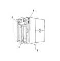
ここで図面を参照すると、図1は、本発明の態様を実施するために用いることができる1つの立体自由造形システムを示す。図1の立体自由造形システム100は、バルク粉末状物質のような構成材料を用いて、所望の物体の個々の層を形成する。多量の粉末が供給チャンバから供給されて、各層が構成される。好ましくは移動ステージ103内に組み込まれるローラが製造チャンバ102の上側に粉末を散布し、所望の厚みまで圧縮する。 Referring now to the drawings, FIG. 1 illustrates one solid freeform system that can be used to implement aspects of the present invention. The three-
流体吐出装置(たとえば、ドロップ・オン・デマンドプリントヘッドのようなインクジェットプリントヘッド)が立体自由造形システム100の移動ステージ103上に配置されることができる。立体自由造形システム100は、吐出されることになる混和しない流体のうちの1つをそれぞれ個別に含む多数の流体吐出装置を含むことができる。別法では、いくつかの実施形態によれば、流体吐出装置は移動ステージ103から離隔して、すなわち構成材料層を散布するステージから離れた第2の移動ステージ上に存在することができる。 A fluid ejection device (eg, an ink jet print head such as a drop-on-demand print head) can be disposed on the moving
上記のように、2つ以上の混和しない流体のうちの1つは、インクによって着色されることができる結合剤であることが好ましい。多数の色の結合剤あるいはインク、および/または結合剤と混和しない1つあるいは複数の流体を収容する、流体吐出装置の多数の区画が存在する場合がある。結合剤には水溶液あるいは水性の溶液を用いることができるが、これに限定されない。いくつかの実施形態によれば、結合剤は約20〜100%が水であり、好ましくは約60〜95%が水である。先に説明されたように、結合剤を用いて、その結合剤が選択的に付着した構成材料が固化される。 As noted above, one of the two or more immiscible fluids is preferably a binder that can be colored by ink. There may be multiple compartments of fluid ejection devices that contain multiple colored binders or inks and / or one or more fluids that are immiscible with the binder. The binder can be an aqueous solution or an aqueous solution, but is not limited thereto. According to some embodiments, the binder is about 20-100% water, preferably about 60-95% water. As explained above, a binder is used to solidify the constituent material to which the binder is selectively attached.
2つ以上の混和しない流体のうちの他方の流体は、結合剤と混和しない剥離流体あるいは拡散制御物質である。剥離流体には、結合剤と混和しない油あるいは他の流体を用いることができる。たとえば、結合剤が水性である場合には、剥離流体は、限定はしないが、シリコーン油、無極性炭化水素(室温で不揮発性であるものが好ましい)、塩化溶剤および液体フッ化炭化水素を含むことができる。シリコーン油は、人体に対して良性であるために特に有用であるが、任意の2つの混和しない流体を用いることができる。しかしながら、結合剤が非水性物質である場合には、剥離流体には、(a)粉末と反応(すなわち、粉末粒子と互いに結合)せず、かつ(b)結合剤と混和しない、他の流体を用いることができる。したがって、剥離流体の選択は、用いられる構成材料および結合剤の特性による。 The other of the two or more immiscible fluids is a release fluid or diffusion control material that is immiscible with the binder. The stripping fluid can be an oil or other fluid that is immiscible with the binder. For example, if the binder is aqueous, the release fluid includes, but is not limited to, silicone oil, nonpolar hydrocarbons (preferably non-volatile at room temperature), chlorinated solvents and liquid fluorinated hydrocarbons. be able to. Silicone oil is particularly useful because it is benign to the human body, but any two immiscible fluids can be used. However, if the binder is a non-aqueous material, the release fluid may include other fluids that (a) do not react with the powder (ie, bind to the powder particles together) and (b) are not miscible with the binder. Can be used. Therefore, the choice of release fluid depends on the properties of the constituent materials and the binder used.
必須ではないが、剥離流体は結合剤よりもかなり高い粘度を有することが望ましい。高い粘度の剥離流体を選択することにより、剥離流体が構成材料の中に拡散する傾向が低減される。また、必須ではないが、剥離流体よりも粘度が低い結合剤を選択することも望ましい。低い粘度の結合剤は、迅速な浸潤および粉末状の構成材料との相互作用を容易にする。したがって、1つの特定の実施形態は、水溶性の結合剤と、それより粘度が高いシリコーン油とを含む。 Although not required, it is desirable for the release fluid to have a much higher viscosity than the binder. By selecting a high viscosity release fluid, the tendency of the release fluid to diffuse into the component material is reduced. Also, although not essential, it is also desirable to select a binder that has a lower viscosity than the release fluid. Low viscosity binders facilitate rapid infiltration and interaction with powdered components. Accordingly, one particular embodiment includes a water soluble binder and a higher viscosity silicone oil.
さらに、結合剤および剥離流体のために用いられる材料を逆にすることができることは理解されよう。すなわち、実施形態によっては、剥離流体を水溶性あるいは水性にし(先に記載されたのと同じパーセンテージ、あるいは他のパーセンテージによる)、結合剤が、剥離流体について先に記載された油あるいは他の材料を含むことができる。しかしながら、2つ以上の混和しない流体は、先に記載された材料セットには限定されない。結合剤が実際に条件どおりに構成材料を結合しさえすれば、任意の2つの混和しない流体を用いることができるものと考えられる。2つ以上の混和しない流体を、結合可能なバルク粉末のような構成材料と組み合わせて、立体自由造形システムにおいて用いるための材料セットを形成することができる。 It will further be appreciated that the materials used for the binder and release fluid can be reversed. That is, in some embodiments, the release fluid is water-soluble or aqueous (by the same percentage as described above, or other percentages) and the binder is an oil or other material previously described for the release fluid. Can be included. However, the two or more immiscible fluids are not limited to the material set described above. It is believed that any two immiscible fluids can be used as long as the binder actually binds the constituent materials as per the conditions. Two or more immiscible fluids can be combined with a constituent material such as a bindable bulk powder to form a material set for use in a three-dimensional freeform system.
立体自由造形システム100の流体吐出装置は、形成されることになる物体を画定する電子データにしたがって、2つ以上の混和しない流体を所定のパターンで構成材料に付着させる。剥離流体は、物体境界の場所において、2次元のパターンで構成材料の層内に付着あるいは堆積させることができる。したがって、剥離流体は水平な上側および下側物体表面において濃密なパターンで付着することができ、垂直あるいは角度のある表面を含む物体の内側断面の周辺部に付着することができる。剥離流体は、形成されている物体の意図された表面の各断面層に堆積され得る。 The fluid ejection device of the three-dimensional free-
また流体吐出装置は、2次元のパターンで、製造チャンバ102の構成材料層内に結合剤を付着あるいは堆積させる。結合剤を十分に含浸させたこの2次元のパターンは、形成されている物体の1つの断面である。先に述べられたように、結合剤はインクで着色され、形成されている物体の個々の断面のための所望の色あるいは色パターンを与えることができる。剥離流体は、結合剤が付着する前に付着させることができる。しかしながら、剥離流体、結合剤および粉末の新たな層は任意の順序で付着させることができるか、剥離流体、結合剤および/または粉末を数回に分けて付着させることができる。 The fluid ejection device attaches or deposits the binder in the constituent material layer of the
粉末状の構成材料は、結合剤が堆積されたエリアにおいて結合されるようになり、それにより、形成されている物体の1つの層が形成される。この工程は製造チャンバ102において先行する層の上に付着(塗布)する粉末の新たな層で繰り返される。その際、所望の物体の次の断面が結合剤および剥離流体を十分に含浸する。剥離流体は物体境界あるいは物体境界の一部のみに付着する。構成材料層そのものを結合することに加えて、結合剤は、形成されている物体の隣接する層あるいは連続する層を結合するための役割も果たす。 The powdered constituent material becomes bonded in the area where the binder is deposited, thereby forming one layer of the object being formed. This process is repeated with a new layer of powder deposited (applied) on the preceding layer in the
この工程は、製造チャンバ102において物体全体が粉末ベッド内(或いは粉末状構成材料の塗布を行う台上)に形成されるまで継続される。結合剤および剥離流体部分によって結合されない余分な構成材料は、ブラシで払い落とされるか、あるいは洗い流されることができ、仕上げられた物体が残される。ユーザインターフェースあるいはコントロールパネル104が設けられ、ユーザが製造工程を制御できるようにする。 This process is continued until the entire object is formed in the powder bed (or on the table on which the powdery constituent material is applied) in the
上記のように、立体自由造形システム100の移動ステージ103は、着色された結合剤および剥離流体を構成材料の層内に選択的に吐出するために、ドロップ・オン・デマンドあるいは連続インクジェット装置のようなインクジェット技術を含むことができる。インクジェット技術を用いるとき、移動ステージ103は、選択されたパターンでインクおよび/または結合剤を吐出して、製造中の物体を形成するために、先に説明されたような1つあるいは複数の流体吐出装置を含むことができる。 As described above, the moving
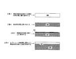
しかしながら、構成材料に結合剤およびインクのみを付着させる代わりに、形成中の物体の表面を画定するために、構成材料の各層に剥離流体も付着させることができる。図2Aはさらに、この技法による立体自由造形方法を示す。図2Aに示されるように、立体自由造形によって物体201を形成する工程は通常、構成材料(たとえば、粉末あるいはスラリー)200の層で開始する。結合剤流体の拡散を抑制し、物体201の周囲にきれいな剥離外層を生成して、物体の表面を滑らかにし、表面をきめ細かく、正確な形状にする。このため、剥離流体を物体境界に付着させる。 However, instead of depositing only the binder and ink on the component material, a release fluid can also be deposited on each layer of the component material to define the surface of the object being formed. FIG. 2A further illustrates a three-dimensional freeform fabrication method according to this technique. As shown in FIG. 2A, the process of forming the
ある構造を物体形状に近づけるとき、最初に剥離流体を物体形状の下にある領域に付着させる。この領域は、その目的が粘度の低い結合流体の拡散を十分に制御できるようにすることであるので、物体形状の厳密な境界を越えて延在することができる。本発明の種々の実施形態によれば、物体の最初の層204の前に、1つあるいは複数の構成材料層に剥離流体を付着させることができる。剥離流体を含む1つあるいは複数の構成層が、剥離層202を画定する。好ましい実施形態では、剥離流体は、物体形状を構成する最初の層の前に構成材料の概ね2つの層に付着する。剥離流体を含む構成材料の層は、それを超えて結合剤流体が拡散せず、かつ、形成中の物体201の底面206を画定するような明確な境界を与える。剥離流体/剥離層が結合剤流体と混和しないので、結合剤流体は剥離層202を越えて拡散しないであろう。 When bringing a structure closer to the object shape, first a release fluid is deposited on the area under the object shape. This region can extend beyond the exact boundary of the object shape, since its purpose is to allow sufficient control of the diffusion of the low viscosity binding fluid. According to various embodiments of the present invention, a release fluid may be applied to one or more constituent material layers prior to the
図2Bに示される本発明の一実施形態によれば、構成材料の層が剥離層202上全体に散布される。剥離層202上全体に散布される構成材料のこの層は、結合剤を付着させると、物体(201、図2A)の第1の層204になる。剥離層202と第1の層204との間の界面は、物体の水平な底面あるいは境界206を画定する。 According to one embodiment of the invention shown in FIG. 2B, a layer of constituent material is spread over the
図2Cに示される本発明の別の実施形態によれば、ある量の結合剤225を、物体201の第1の層204を含んで形成されることになる物体形状の領域内にある剥離層202の上側に直に付着させることができる。その後、構成材料の層が散布され、さらに別の結合剤を、図示される第1の層204を生成するために、形成されている物体の形状内に付着させることができる。剥離層202と第1の層204との間の界面は、物体の水平な底面あるいは境界206を画定する。 In accordance with another embodiment of the present invention shown in FIG. 2C, a release layer that is in a region of the object shape that will be formed with an amount of
さらに、再び図2Aを参照すると、ある量の剥離流体を、第1の層204の部分(208および210)、および形成されている物体のその層内にある境界に隣接する後続の物体層の部分に選択的に付着させる。第1の層204の剥離部分208および210、および後続の層の剥離部分は、そこを越えて結合流体が拡散しない垂直な境界を提供する。 Further, referring again to FIG. 2A, an amount of stripping fluid is applied to portions of the first layer 204 (208 and 210) and to subsequent object layers adjacent to boundaries within that layer of the object being formed. Selectively attach to the part. The peeled
その後、形成されている物体201を表す電子データにしたがって、ある量の結合剤流体を、第1の層204の剥離部分208および210の間に付着させる。結合剤は、所望の物体になる粉末を固化する。剥離部分208および210と第1の層204の境界部分との間の界面は、物体201の垂直な表面あるいは境界212および214を画定する。底面206および垂直な表面212および214は、さらに以下に記載されるように、剥離流体が結合剤流体と混和しないので、非常に滑らかであり、明確である。仕上げられた物体は肉眼で(マクロなスケールで)見た場合には水平および垂直な表面のみを有するようには見えない場合もあるが、物体201は、微小な尺度(ミクロなスケール)において、各層が剥離部分202/208/210等によって画定される水平および垂直な表面206/212/214等を含むように層状に形成される。 Thereafter, an amount of binder fluid is deposited between the peeled
この層形成工程は、物体201を生成するために必要とされる回数だけ何度も繰り返され、各層が、結合剤の拡散を制限し、滑らかな物体表面を画定する剥離部分を含むようにすることが好ましい。図2Aの例では、物体のさらに別の第2の層、第3の層および第4の層216/218/220のみが示されており、それぞれ物体境界あるいは外側表面212および214において剥離流体を含む層部分それぞれ222/224/226を有する。 This layering process is repeated as many times as necessary to produce the
図2Dは、剥離流体を用いて適当に画定された垂直な物体境界を製造するこの方法をさらに示す。図2Dによれば、結合剤を付着させる前に、剥離流体が剥離部分210に加えられる。しかしながら、いくつかの実施形態によれば、結合剤を最初に付着させる。 FIG. 2D further illustrates this method of producing a properly defined vertical object boundary using a release fluid. According to FIG. 2D, a release fluid is added to the
境界物体領域が次の層において、その領域の上に直に、さらに別の物体形状を持たないときに、これが少なくとも部分的には、図2Eに示されるように最後の、あるいは最も上の物体層220であると見なされる。ある領域が、考慮の対象となる領域内の最も上の層と見なされる場合に、必ずしも、この層あるいは後続の層内の他の場所に残りの物体形状が形成されないとは限らない。最も上の層の領域では、物体201の最も上の層220に結合剤を付着させた後に、本発明の数多くの実現可能な実施形態による種々のステップが実行される場合もある。 When the boundary object region has no further object shape directly on it in the next layer, this is at least partly the last or top object as shown in FIG.
図2Eの実施形態によれば、最後の、あるいは最も上の物体層220に結合剤を付着させた直後に、剥離流体225を付着させることができる。構成材料のさらに別の層230が、剥離流体225を吸収した最後の物体層220上に塗布される場合もある。 According to the embodiment of FIG. 2E, the
図2Fに示されるような他の実施形態は、最も上の層の領域上に剥離流体を付着させる前に、最後の、あるいは最も上の層220上に構成材料のさらに別の層230を塗布することもできる。当然、最も上の層の領域は、物体および現在の構造の両方の最後の層でもある場合には、剥離流体および構成材料の付着がそれ以上は実行されない場合もある。 Another embodiment, as shown in FIG. 2F, applies yet another
当然、物体の全ての層が完成したとき、その物体は、その物体の表面に隣接して付着した剥離流体から形成される剥離外層で少なくとも部分的に覆われることになることは理解されよう。さらに、いくつかの実施形態では、物体のある特定の領域あるいは層は、剥離流体部分を全く含まない場合もある。 Of course, it will be appreciated that when all layers of an object are complete, the object will be at least partially covered with a release outer layer formed from a release fluid deposited adjacent to the surface of the object. Further, in some embodiments, certain areas or layers of the object may not include any release fluid portion.
図3は、形成されている物体の内側断面層(たとえば、図2に示される層216/218/220)の平面図である。簡単にするために、形成されている物体302は単に長方形のブロックとしている。 FIG. 3 is a plan view of an inner cross-sectional layer (eg,
構成材料粉末および剥離流体から形成される剥離外層300が、物体302の周辺に配置される。剥離外層300は図面では連続した周辺部として示されるが、いくつかの実施形態によれば、剥離外層300内には不連続な部分が存在する場合もある。物体層を固化するために、結合剤流体が構成材料内、すなわち剥離外層300の内側に吐出される。さらに、結合剤流体および剥離流体は混和しないので、結合剤流体は、剥離外層300と物体の302の周辺部との間の界面304を越えて拡散しない。結合剤流体と剥離流体とが混和しない結果として、物体境界が良好に画定され、表面が滑らかになる。 A release
図2Aを参照して先に説明されたように、剥離層部分222等と物体層204等との間の界面は物体表面206/212/214を画定する。以前の立体自由造形方法によれば、通常、結合剤が構成材料の中に自由に拡散できるようになり、結果として表面が粗く、寸法が不正確になるのに対して、2つ以上の混和しない流体を用いることにより、物体の周囲にきれいな剥離外層が生成される。滑らかな表面206/212/214を挟んで、混和しない物体層204等と剥離層あるいは部分202/208等は互いに「はじき合い」、それゆえその接触面積を最小限に抑える。 As previously described with reference to FIG. 2A, the interface between the
混和しない物質が、良好に画定された界面において混合することがなく、代わりに互いに「はじき合う」という利点を本開示が有することは当業者にはよく知られている。構成材料内に、所定のパターンで付着する2つ以上の混和しない流体が存在する結果として、結合剤を十分に含浸した構成材料と剥離流体を十分に含浸した構成材料との間の界面において、界面エネルギーあるいは張力が増加するようになる。混和しない物質を分離する界面の面積が大きくなると、界面エネルギーが高くなる。平衡状態に達するために全てのシステムはそのエネルギーを最小限に抑える(熱力学の原理の1つ)ので、2つ以上の混和しない物質は互いの接触面積を最小限に抑える。それゆえ、剥離流体を含む層部分が、結合剤流体を含む層部分との接触面積を最小限に抑えるので、製造される物体の表面積も低減される。物体の表面積を低減する結果として、その表面が滑らかになる。 It is well known to those skilled in the art that the present disclosure has the advantage that immiscible materials do not mix at well-defined interfaces and instead “repel” each other. As a result of the presence of two or more immiscible fluids that adhere in a predetermined pattern within the constituent material, at the interface between the constituent material fully impregnated with the binder and the constituent material sufficiently impregnated with the release fluid, Interfacial energy or tension increases. As the area of the interface separating the immiscible substances increases, the interfacial energy increases. Since all systems minimize their energy to reach equilibrium (one of the principles of thermodynamics), two or more immiscible materials minimize the contact area with each other. Therefore, the surface area of the manufactured object is also reduced because the layer portion containing the release fluid minimizes the contact area with the layer portion containing the binder fluid. As a result of reducing the surface area of the object, its surface becomes smooth.
さらに、構成材料内に吐出される剥離流体および結合剤流体が混和しないので、物体の境界において構成材料に剥離流体を付着させることにより、結合剤流体の拡散が停止することになる場所が極めて正確に画定される。正確な境界制御は、表面を滑らかにするのを容易にするだけでなく、表面形状の寸法精度も改善する。さらに、物体境界が剥離流体によって画定されるので、いくつの装置が結合剤流体を付着させるために用いられるかにかかわらず、流体吐出装置の位置合わせ不良に起因する寸法精度の損失が少なくなる。 Furthermore, since the release fluid and binder fluid that are discharged into the component material are immiscible, it is very precise where the binder fluid diffusion will stop by attaching the release fluid to the component material at the boundary of the object. Defined. Accurate boundary control not only facilitates smoothing the surface, but also improves the dimensional accuracy of the surface shape. Further, since the object boundary is defined by the release fluid, there is less loss of dimensional accuracy due to misalignment of the fluid ejection device, regardless of how many devices are used to deposit the binder fluid.
さらに、物体境界において用いられる結合剤の量を最小限に抑えて、余分に拡散させないようにして層を固化するという通常の利用法の代わりに、剥離流体を付着させることにより物体境界内の結合剤含浸レベルをより高く(好ましくは最適に)することができる場合もある。物体境界における結合剤含浸レベルを最適にする結果として、物体境界において結合剤レベルを最小限に抑える従来の工程に比べて、物体の強度が高くなる。 In addition, bonding within the object boundary can be accomplished by depositing a release fluid instead of the usual use of solidifying the layer with minimal amount of binder used at the object boundary and avoiding extra diffusion. In some cases, the agent impregnation level may be higher (preferably optimal). As a result of optimizing the binder impregnation level at the object boundary, the strength of the object is higher compared to conventional processes that minimize the binder level at the object boundary.
上記の方法にしたがって物体が完成されたとき、図4の例に示されるように、物体402を少なくとも部分的に包む外側剥離層400が存在する。外側剥離層400は生成される物体402の一部ではなく、代わりに、物体402の外側表面404を画定する物体境界層になる。それゆえ、外側剥離層400はベースあるいは仕上げられた物体402が見えるようにするために除去される。 When the object is completed according to the above method, there is an
いくつかの実施形態によれば、剥離層400は単にブラシで払い落とされることができる。しかしながら、剥離層400が油を用いる流体あるいは他の物質で生成されるときには、剥離層400および残された任意の油または他の剥離流体を除去するために、物体402は洗浄剤、溶剤あるいは他の物質で洗浄される場合もある。 According to some embodiments, the
別の実現可能な実施形態では、剥離層は、粉末状の構成材料によって吸収された後に固化する噴射された液体である材料によって形成されることができる。噴射された液体には、物体の周囲温度より高い凝固点を有する蝋を用いることができるであろう。蝋は結合剤流体に対して非湿潤性であり、かつ不混和性(不溶性)であろう。 In another feasible embodiment, the release layer can be formed of a material that is a jetted liquid that solidifies after being absorbed by the powdered component material. For the jetted liquid, a wax having a freezing point higher than the ambient temperature of the object could be used. The wax will be non-wetting with the binder fluid and immiscible (insoluble).
上記の実施形態は本発明の原理およびその実際の応用形態を最もわかりやすく例示するために選択され、説明されてきた。上記の説明は、当業者が、考慮される個々の用途に相応しいように、種々の実施形態および種々の変更形態において本発明を最も効果的に利用できるようにすることを意図している。本発明の範囲は添付の特許請求項によって規定されることを意図している。 The above embodiments have been selected and described in order to best illustrate the principles of the invention and its practical application. The above description is intended to enable those skilled in the art to most effectively utilize the present invention in various embodiments and modifications, as appropriate to the particular application considered. The scope of the present invention is intended to be defined by the appended claims.
本発明は、以下の実施態様を含んでいる。 The present invention includes the following embodiments.
<1> 立体自由造形によって物体(201)を形成する方法であって、物体の構成材料に2つの混和しない流体を付着させる工程を含むことを特徴とする方法。 <1> A method for forming an object (201) by three-dimensional free shaping, which includes a step of attaching two immiscible fluids to a constituent material of the object.
<2> 前記2つの混和しない流体のうちの第1の流体は前記構成材料を選択的に固化するために用いられる結合剤(225)を含むことを特徴とする、上記<1>に記載の方法。 <2> The first fluid of the two immiscible fluids includes a binder (225) used to selectively solidify the constituent material, according to <1> above Method.
<3> 前記2つの混和しない流体のうちの第2の流体は物体境界において付着する剥離流体を含むことを特徴とする、上記<2>に記載の方法。 <3> The method according to <2>, wherein the second fluid of the two immiscible fluids includes a peeling fluid that adheres at an object boundary.
<4> 前記立体自由造形は流体吐出する工程を含み、前記方法はさらに、所定のパターンで前記構成材料上に前記2つの混和しない流体の液滴を吐出する工程を含むことを特徴とする、上記<1>に記載の方法。 <4> The three-dimensional free-formation includes a step of discharging fluid, and the method further includes a step of discharging droplets of the two immiscible fluids on the constituent material in a predetermined pattern. The method according to <1> above.
<5> 立体自由造形用の材料セットであって、バルク粉末物質と、結合剤流体と、該結合剤流体と混和しない拡散制御物質とを含むことを特徴とする、立体自由造形材料セット。 <5> A three-dimensional free shaping material set, comprising a bulk powder substance, a binder fluid, and a diffusion control substance that is immiscible with the binder fluid.
<6> 立体自由造形において結合剤の拡散を制御あるいは制限する方法であって、物体表面に剥離流体を付着させる工程を含み、前記剥離流体は物体(201)の構成材料、物体構成材料の結合剤、あるいはその両方と混和しないことを特徴とする方法。 <6> A method of controlling or restricting diffusion of a binder in a three-dimensional free-formation, including a step of attaching a peeling fluid to an object surface, the peeling fluid being a constituent material of an object (201) and a binding of the object constituent material A method characterized by being immiscible with the agent or both.
<7> 電子データから所望の物体(201)を形成するための立体自由造形システム(100)であって、粉末状の構成材料のベッドを保持するための製造チャンバ(102)と、該製造チャンバ(102)において粉末の連続した層を散布するための移動ステージ(103)と、粉末からなる各層にある量の結合剤を選択的に吐出し、かつ物体境界において粉末の層にある量の剥離流体を吐出するための流体吐出装置とを含み、前記剥離流体は前記結合剤と混和しないことを特徴とする、立体自由造形システム。 <7> A three-dimensional free-formation system (100) for forming a desired object (201) from electronic data, a manufacturing chamber (102) for holding a bed of powdery constituent materials, and the manufacturing chamber A moving stage (103) for spraying successive layers of powder in (102), and selectively discharging a certain amount of binder in each layer of powder and a certain amount of peeling in the powder layer at the object boundary A three-dimensional free-formation system comprising: a fluid discharge device for discharging a fluid, wherein the release fluid is not miscible with the binder.
<8> 立体自由造形によって物体(201)を製造する方法であって、構成材料の層を堆積する工程、前記構成材料の層上に第1の流体を堆積する工程、前記構成材料の層上に第2の流体を堆積する工程、とを含み、前記第1の流体は前記第2の流体と混和しないことを特徴とする方法。 <8> A method of manufacturing an object (201) by three-dimensional free shaping, the step of depositing a layer of constituent material, the step of depositing a first fluid on the layer of constituent material, and on the layer of constituent material Depositing a second fluid on the first fluid, wherein the first fluid is immiscible with the second fluid.
<9> インクジェット工程を用いて、製造されている物体(201)の連続した断面を形成する立体自由造形システム(100)によって製造される物体(201)の表面の粗さを低減する方法であって、物体境界において拡散抑制流体を付着させる工程を含むことを特徴とする方法。 <9> A method for reducing the roughness of the surface of an object (201) manufactured by a three-dimensional free-formation system (100) that forms a continuous cross section of the object (201) being manufactured using an inkjet process. And depositing a diffusion-inhibiting fluid at the object boundary.
<10> 立体自由造形によって形成される物体(201)上の所望の表面仕上げを生成する方法であって、前記物体(201)の周囲に剥離外層(300)を形成するために2つの混和しない流体を用いる工程を含むことを特徴とする方法。 <10> A method for producing a desired surface finish on an object (201) formed by three-dimensional free-formation, wherein two are not mixed to form a peeling outer layer (300) around the object (201) A method comprising the step of using a fluid.
本発明は、3次元の物体、たとえば、プロタイプ部品、モデルおよび加工工具を製造するために利用できる。 The present invention can be used to produce three-dimensional objects such as protyping parts, models and processing tools.
100 立体自由造形システム
102 製造チャンバ
103 移動ステージ
104 ユーザインターフェースあるいはコントロールパネル
200 構成材料
201 物体
202 剥離層
204 第1の層
206 底面
208 剥離部分
210 剥離部分
212 垂直な境界
214 垂直な境界
216 第2の層
218 第3の層
220 第4の層
222 剥離流体を含む層部分
224 剥離流体を含む層部分
226 剥離流体を含む層部分
300 剥離外層
302 物体
304 界面
400 外側剥離層
402 物体
404 外側表面100 Three-dimensional free-
Claims (10)
Translated fromJapanese前記物体の粉末状構成材料の層に、前記粉末状構成材料を固化する結合剤を含有する第1の流体を付着させ、前記物体の断面層を形成する第一工程と、
前記物体の粉末状構成材料の前記層において、前記断面層の外周に、前記物体の外側表面を画定する剥離部分を形成する剥離流体を含有する第2の流体を付着させる第二工程と、
第一工程と第二工程を少なくとも一回行って前記物体の全断面層を形成した後、前記剥離部分を前記物体から除去する第三工程と、を含み、
前記剥離流体が前記結合剤と混和しないことを特徴とする方法。A method of formingan objectmaterial by steric free-form,
A first step of attaching a first fluid containing a binder that solidifies the powdery constituent material to the powdery constituent material layer of the object to form a cross-sectional layer of the object;
In the layer of the powdery constituent material of the object, a second step of attaching a second fluid containing a peeling fluid that forms a peeling portion defining an outer surface of the object to the outer periphery of the cross-sectional layer;
A third step of performing the first step and the second step at least once to form the entire cross-sectional layer of the object, and then removing the peeled portion from the object.
The method wherein the stripping fluid is immiscible with the binder .
前記物体の粉末状構成材料の層において、前記物体の外側表面を画定する剥離部分を形成する剥離流体を、所定のパターンで付着させる第一工程と、 A first step of depositing, in a predetermined pattern, a release fluid that forms a release portion defining an outer surface of the object in a layer of the powdery constituent material of the object;
前記物体の粉末状構成材料の前記層において、前記物体の断面層を形成するため、前記剥離部分に隣接した部分に前記構成材料を固化する結合剤を付着させる第二工程と、 In the layer of the powdery constituent material of the object, a second step of attaching a binder that solidifies the constituent material to a portion adjacent to the peeling portion in order to form a cross-sectional layer of the object;
第一工程と第二工程を少なくとも一回行って前記物体の全断面層を形成した後、前記剥離部分を除去する第三工程と、を含み、 Including performing a first step and a second step at least once to form the entire cross-sectional layer of the object, and then removing the peeled portion.
前記剥離流体が前記結合剤と混和しないことを特徴とする方法。 The method wherein the stripping fluid is immiscible with the binder.
剥離層と前記断面層との間の界面は、前記物体の底面を画定することを特徴とする請求項1又は2に記載の方法。 The method according to claim 1 or 2, wherein an interface between a release layer and the cross-sectional layer defines a bottom surface of the object.
前記バルク粉末物質と、
前記結合剤の流体と、
前記剥離流体を構成する拡散抑制剤であって、前記結合剤の流体と混和しないことにより前記結合剤の流体の拡散を抑制する拡散抑制剤とを含むことを特徴とする、立体自由造形材料セット。To form a cross-sectional layer of an object, a layer of bulk powder material is adhered to each other adjacent to each other with a release fluid that forms a release portion that defines the outer surface of the object and a binder that solidifies the bulk powder material. And a step of removing the peeled portion from the object after forming the entire cross-sectional layer of the object by performing the attaching step at least once ,
The bulk powder material;
Fluidofsaid binder,
A diffusion suppressing agent constituting the release fluid, characterized in that it comprises asuppressingdiffusion controllerdiffusion of fluid in the binder by immiscible fluidofsaid binder, solid free-form material sets .
粉末の構成材料のベッドを保持するための製造チャンバと、 A production chamber for holding a bed of powder constituent materials;
前記製造チャンバにおいて、各層が前記物体の断面層となる粉末の連続した層を散布するための移動ステージと、 A moving stage for spreading a continuous layer of powder, each layer being a cross-sectional layer of the object, in the manufacturing chamber;
粉末の各層に粉末を固化するある量の結合剤を選択的に吐出し、かつ粉末の各層に前記物体の外側表面を画定する剥離部分を形成するある量の剥離流体を吐出し、前記粉末からなる各層において前記結合剤と前記剥離流体を隣接して配置するための流体吐出装置とを含み、 Selectively ejecting a quantity of binder that solidifies the powder into each layer of powder, and ejecting a quantity of release fluid into each layer of powder to form a release portion defining the outer surface of the object; A fluid ejection device for arranging the binder and the stripping fluid adjacent to each other in each of the layers,
全層の形成後に前記剥離部分は前記物体から剥離され、 After the formation of all layers, the peeled portion is peeled from the object,
前記剥離流体が前記結合剤と混和しないことを特徴とする、立体自由造形システム。 A three-dimensional free-formation system, wherein the peeling fluid is immiscible with the binder.
Applications Claiming Priority (1)
| Application Number | Priority Date | Filing Date | Title |
|---|---|---|---|
| US10/376,827US20040169699A1 (en) | 2003-02-28 | 2003-02-28 | Methods and systems for producing an object through solid freeform fabrication using immiscible fluids |
Publications (2)
| Publication Number | Publication Date |
|---|---|
| JP2004262243A JP2004262243A (en) | 2004-09-24 |
| JP4126283B2true JP4126283B2 (en) | 2008-07-30 |
Family
ID=32771508
Family Applications (1)
| Application Number | Title | Priority Date | Filing Date |
|---|---|---|---|
| JP2004048245AExpired - Fee RelatedJP4126283B2 (en) | 2003-02-28 | 2004-02-24 | Method and system for manufacturing objects by three-dimensional free-formation using immiscible fluids |
Country Status (4)
| Country | Link |
|---|---|
| US (1) | US20040169699A1 (en) |
| EP (1) | EP1452298A1 (en) |
| JP (1) | JP4126283B2 (en) |
| TW (1) | TWI301095B (en) |
Families Citing this family (42)
| Publication number | Priority date | Publication date | Assignee | Title |
|---|---|---|---|---|
| JP5338256B2 (en)* | 2008-10-27 | 2013-11-13 | カシオ計算機株式会社 | Stereoscopic image forming apparatus |
| DE102009030113A1 (en) | 2009-06-22 | 2010-12-23 | Voxeljet Technology Gmbh | Method and device for supplying fluids during the layering of models |
| CN102695593B (en) | 2009-12-08 | 2014-12-17 | 赫斯基注塑系统有限公司 | Hot runner system with manifold assembly manufactured according to freeform manufacturing process |
| US8740598B2 (en) | 2009-12-08 | 2014-06-03 | Husky Injection Molding Systems Ltd. | Multi-property injection molding nozzle for a hot-runner system |
| CN104802365A (en) | 2009-12-09 | 2015-07-29 | 赫斯基注塑系统有限公司 | Method for machining hot-runner system |
| JP5668328B2 (en)* | 2010-05-26 | 2015-02-12 | セイコーエプソン株式会社 | Slurry for modeling and modeling method |
| JP2011245713A (en)* | 2010-05-26 | 2011-12-08 | Seiko Epson Corp | Shaping method |
| JP5668327B2 (en)* | 2010-05-26 | 2015-02-12 | セイコーエプソン株式会社 | Slurry for modeling and modeling method |
| JP5471939B2 (en)* | 2010-07-28 | 2014-04-16 | セイコーエプソン株式会社 | Modeling method |
| US8651653B2 (en)* | 2011-07-28 | 2014-02-18 | Xerox Corporation | Apparatus and method for applying release fluid to a leveler in a printing apparatus |
| SE536670C2 (en)* | 2011-08-26 | 2014-05-13 | Digital Metal Ab | Layer-based manufacture of free-form micro-components of multimaterial |
| JP6314991B2 (en)* | 2013-10-03 | 2018-04-25 | コニカミノルタ株式会社 | 3D modeling apparatus and 3D modeling method |
| US10220564B2 (en) | 2014-01-16 | 2019-03-05 | Hewlett-Packard Development Company, L.P. | Generating three-dimensional objects |
| CN105939836B (en) | 2014-01-16 | 2018-05-01 | 惠普发展公司,有限责任合伙企业 | Construction Material Profile |
| US10889059B2 (en) | 2014-01-16 | 2021-01-12 | Hewlett-Packard Development Company, L.P. | Generating three-dimensional objects |
| WO2015108573A1 (en) | 2014-01-16 | 2015-07-23 | Hewlett-Packard Development Company, L.P. | Modifying data representing three-dimensional objects |
| KR101872628B1 (en)* | 2014-01-16 | 2018-06-28 | 휴렛-팩커드 디벨롭먼트 컴퍼니, 엘.피. | Generating a three-dimensional object |
| WO2015106840A1 (en)* | 2014-01-16 | 2015-07-23 | Hewlett-Packard Development Company L.P. | Processing slice data for an additive manufacturing system |
| US10538074B2 (en) | 2014-01-16 | 2020-01-21 | Hewlett-Packard Development Company, L.P. | Processing slice data |
| US11167475B2 (en) | 2014-01-16 | 2021-11-09 | Hewlett-Packard Development Company, L.P. | Generating three-dimensional objects |
| US20170203513A1 (en) | 2014-01-16 | 2017-07-20 | Hewlett-Packard Development Company, L.P. | Generating a three-dimensional object |
| US10544311B2 (en) | 2014-01-16 | 2020-01-28 | Hewlett-Packard Development Company, L.P. | Polymeric powder composition for three-dimensional (3D) printing |
| US10252474B2 (en) | 2014-01-16 | 2019-04-09 | Hewlett-Packard Development Company, L.P. | Temperature determination based on emissivity |
| WO2015108543A1 (en) | 2014-01-16 | 2015-07-23 | Hewlett-Packard Development Company, L.P. | Three-dimensional (3d) printing method |
| JP2015139977A (en) | 2014-01-30 | 2015-08-03 | セイコーエプソン株式会社 | Manufacturing method of three-dimensional structure and three-dimensional structure |
| JP5725220B2 (en)* | 2014-02-06 | 2015-05-27 | セイコーエプソン株式会社 | Modeling method |
| JP5708863B2 (en)* | 2014-04-16 | 2015-04-30 | セイコーエプソン株式会社 | Modeling method |
| JP5904231B2 (en)* | 2014-04-16 | 2016-04-13 | セイコーエプソン株式会社 | Modeling method |
| DE112014006447T5 (en)* | 2014-04-30 | 2016-11-24 | Hewlett-Packard Development Company, L.P. | Computational model and three-dimensional (3D) printing method |
| CN106687281B (en)* | 2014-09-02 | 2019-12-20 | 惠普发展公司有限责任合伙企业 | Additive manufacturing for overhanging portion |
| US11117322B2 (en)* | 2015-01-14 | 2021-09-14 | Hewlett-Packard Development Company, L.P. | Additive manufacturing |
| WO2016119889A1 (en)* | 2015-01-30 | 2016-08-04 | Hewlett-Packard Development Company, L.P. | Fabricating three dimensional objects |
| EP3271150B1 (en) | 2015-07-09 | 2021-08-25 | Hewlett-Packard Development Company, L.P. | Generating three-dimensional objects with target surface roughness |
| US9987682B2 (en) | 2016-08-03 | 2018-06-05 | 3Deo, Inc. | Devices and methods for three-dimensional printing |
| EP4342605A3 (en) | 2016-08-03 | 2024-08-14 | 3Deo, Inc. | Devices and methods for three-dimensional printing |
| JP6874531B2 (en)* | 2017-05-29 | 2021-05-19 | コニカミノルタ株式会社 | Manufacturing method of three-dimensional model, powder material used for it, and fluid for bonding |
| DK3473441T3 (en)* | 2017-10-23 | 2021-08-23 | Gen Electric | MOVABLE MOLDING DEVICE FOR ADDITIONAL MANUFACTURE |
| EP3511163B1 (en)* | 2018-01-12 | 2024-03-20 | Concept Laser GmbH | Method for operating an apparatus for additively manufacturing of three-dimensional objects |
| WO2019157074A2 (en)* | 2018-02-07 | 2019-08-15 | 3Deo, Inc. | Devices, systems and methods for printing three-dimensional objects |
| JP6546306B2 (en)* | 2018-03-01 | 2019-07-17 | ヒューレット−パッカード デベロップメント カンパニー エル.ピー.Hewlett‐Packard Development Company, L.P. | Generation of three-dimensional object |
| JP7087482B2 (en)* | 2018-03-13 | 2022-06-21 | 株式会社リコー | Three-dimensional modeling device and three-dimensional modeling method |
| US12103229B2 (en)* | 2019-03-15 | 2024-10-01 | Ricoh Company, Ltd. | Jettable temporary binders to create removable support materials |
Family Cites Families (9)
| Publication number | Priority date | Publication date | Assignee | Title |
|---|---|---|---|---|
| US106412A (en)* | 1870-08-16 | Improvement in railway-car brakes | ||
| US5136515A (en)* | 1989-11-07 | 1992-08-04 | Richard Helinski | Method and means for constructing three-dimensional articles by particle deposition |
| US5387380A (en)* | 1989-12-08 | 1995-02-07 | Massachusetts Institute Of Technology | Three-dimensional printing techniques |
| US5518680A (en)* | 1993-10-18 | 1996-05-21 | Massachusetts Institute Of Technology | Tissue regeneration matrices by solid free form fabrication techniques |
| JP3152326B2 (en)* | 1993-12-24 | 2001-04-03 | 株式会社ケーネットシステムズ | Additive manufacturing method and additive manufacturing apparatus |
| US5660621A (en)* | 1995-12-29 | 1997-08-26 | Massachusetts Institute Of Technology | Binder composition for use in three dimensional printing |
| US6007318A (en)* | 1996-12-20 | 1999-12-28 | Z Corporation | Method and apparatus for prototyping a three-dimensional object |
| US6454972B1 (en)* | 1999-11-24 | 2002-09-24 | Sandia Corporation | Solid freeform fabrication using chemically reactive suspensions |
| AU2001273687A1 (en)* | 2000-07-10 | 2002-01-21 | Massachusetts Institute Of Technology | Method and materials for controlling migration of binder liquid in a powder |
- 2003
- 2003-02-28USUS10/376,827patent/US20040169699A1/ennot_activeAbandoned
- 2003-09-05TWTW092124590Apatent/TWI301095B/ennot_activeIP Right Cessation
- 2004
- 2004-02-09EPEP04250691Apatent/EP1452298A1/ennot_activeWithdrawn
- 2004-02-24JPJP2004048245Apatent/JP4126283B2/ennot_activeExpired - Fee Related
Also Published As
| Publication number | Publication date |
|---|---|
| US20040169699A1 (en) | 2004-09-02 |
| TW200416123A (en) | 2004-09-01 |
| TWI301095B (en) | 2008-09-21 |
| JP2004262243A (en) | 2004-09-24 |
| EP1452298A1 (en) | 2004-09-01 |
Similar Documents
| Publication | Publication Date | Title |
|---|---|---|
| JP4126283B2 (en) | Method and system for manufacturing objects by three-dimensional free-formation using immiscible fluids | |
| EP1442870B1 (en) | Methods and systems for producing an object through solid freeform fabrication by varying a concentration of ejected material applied to an object layer | |
| US10960655B2 (en) | Articles and structures prepared by three-dimensional printing method | |
| TWI279323B (en) | Methods and systems for producing an object through solid freeform fabrication | |
| JP5059832B2 (en) | Method and apparatus for prototyping a three-dimensional object | |
| US7435072B2 (en) | Methods and systems for producing an object through solid freeform fabrication | |
| US9505176B2 (en) | Method for producing three-dimensional components | |
| US20100021638A1 (en) | Method for fabricating three dimensional models | |
| US7625512B2 (en) | Method and a system for producing an object using solid freeform fabrication | |
| US20040251574A1 (en) | Methods to produce an object through solid freeform frabrication | |
| TWI659940B (en) | Sintering and shaping method and sintered shaped article | |
| US6423255B1 (en) | Method for manufacturing a structural part by deposition technique | |
| US20050074596A1 (en) | Method and system for using porous structures in solid freeform fabrication | |
| EP3600724B1 (en) | Method for additive manufacturing with powder material | |
| JP2005120475A (en) | Apparatus and method for manufacturing three-dimensional metallic object | |
| EP1520686A3 (en) | Fabrication of three-dimensional objects | |
| WO2006091842A1 (en) | Core-shell solid freeform fabrication method and apparatus | |
| CN106804106A (en) | Multi-material 3D printer | |
| CN106414040A (en) | 3D reverse image printing method and apparatus | |
| KR20130099881A (en) | Additive fabrication technologies for creating molds for die components | |
| JP2005297325A (en) | 3D modeling method and 3D model | |
| JP2005119302A (en) | Organic-inorganic hybrid composition for solid-molding | |
| JP2009006629A (en) | Apparatus for sealing opening end of honeycomb structure | |
| JP2017196890A (en) | 3D modeling apparatus and 3D modeling method | |
| JP6880492B2 (en) | 3D modeling equipment, manufacturing methods and programs for 3D models |
Legal Events
| Date | Code | Title | Description |
|---|---|---|---|
| A977 | Report on retrieval | Free format text:JAPANESE INTERMEDIATE CODE: A971007 Effective date:20070416 | |
| A131 | Notification of reasons for refusal | Free format text:JAPANESE INTERMEDIATE CODE: A131 Effective date:20070424 | |
| A601 | Written request for extension of time | Free format text:JAPANESE INTERMEDIATE CODE: A601 Effective date:20070723 | |
| A602 | Written permission of extension of time | Free format text:JAPANESE INTERMEDIATE CODE: A602 Effective date:20070726 | |
| A521 | Request for written amendment filed | Free format text:JAPANESE INTERMEDIATE CODE: A523 Effective date:20070824 | |
| TRDD | Decision of grant or rejection written | ||
| A01 | Written decision to grant a patent or to grant a registration (utility model) | Free format text:JAPANESE INTERMEDIATE CODE: A01 Effective date:20080430 | |
| A01 | Written decision to grant a patent or to grant a registration (utility model) | Free format text:JAPANESE INTERMEDIATE CODE: A01 | |
| A61 | First payment of annual fees (during grant procedure) | Free format text:JAPANESE INTERMEDIATE CODE: A61 Effective date:20080512 | |
| R150 | Certificate of patent or registration of utility model | Free format text:JAPANESE INTERMEDIATE CODE: R150 | |
| FPAY | Renewal fee payment (event date is renewal date of database) | Free format text:PAYMENT UNTIL: 20110516 Year of fee payment:3 | |
| FPAY | Renewal fee payment (event date is renewal date of database) | Free format text:PAYMENT UNTIL: 20120516 Year of fee payment:4 | |
| FPAY | Renewal fee payment (event date is renewal date of database) | Free format text:PAYMENT UNTIL: 20130516 Year of fee payment:5 | |
| FPAY | Renewal fee payment (event date is renewal date of database) | Free format text:PAYMENT UNTIL: 20130516 Year of fee payment:5 | |
| R250 | Receipt of annual fees | Free format text:JAPANESE INTERMEDIATE CODE: R250 | |
| LAPS | Cancellation because of no payment of annual fees |