JP4124654B2 - Intravascular temperature sensor - Google Patents
Intravascular temperature sensorDownload PDFInfo
- Publication number
- JP4124654B2 JP4124654B2JP2002568981AJP2002568981AJP4124654B2JP 4124654 B2JP4124654 B2JP 4124654B2JP 2002568981 AJP2002568981 AJP 2002568981AJP 2002568981 AJP2002568981 AJP 2002568981AJP 4124654 B2JP4124654 B2JP 4124654B2
- Authority
- JP
- Japan
- Prior art keywords
- catheter
- balloon
- temperature sensor
- cowl
- temperature
- Prior art date
- Legal status (The legal status is an assumption and is not a legal conclusion. Google has not performed a legal analysis and makes no representation as to the accuracy of the status listed.)
- Expired - Fee Related
Links
- 210000004204blood vesselAnatomy0.000claimsabstractdescription69
- 239000008280bloodSubstances0.000claimsdescription19
- 210000004369bloodAnatomy0.000claimsdescription19
- 230000017531blood circulationEffects0.000claimsdescription10
- 239000012530fluidSubstances0.000claimsdescription5
- 238000013507mappingMethods0.000claimsdescription4
- 238000000034methodMethods0.000abstractdescription6
- 239000004020conductorSubstances0.000description13
- 230000002596correlated effectEffects0.000description6
- 210000001519tissueAnatomy0.000description5
- 201000001320AtherosclerosisDiseases0.000description4
- 239000007779soft materialSubstances0.000description4
- 206010061218InflammationDiseases0.000description3
- 206010052428WoundDiseases0.000description3
- 208000027418Wounds and injuryDiseases0.000description3
- 210000001367arteryAnatomy0.000description3
- 230000036760body temperatureEffects0.000description3
- 208000019622heart diseaseDiseases0.000description3
- 208000015181infectious diseaseDiseases0.000description3
- 230000004054inflammatory processEffects0.000description3
- 239000000463materialSubstances0.000description3
- 238000002399angioplastyMethods0.000description2
- 238000013459approachMethods0.000description2
- HVYWMOMLDIMFJA-DPAQBDIFSA-NcholesterolChemical compoundC1C=C2C[C@@H](O)CC[C@]2(C)[C@@H]2[C@@H]1[C@@H]1CC[C@H]([C@H](C)CCCC(C)C)[C@@]1(C)CC2HVYWMOMLDIMFJA-DPAQBDIFSA-N0.000description2
- 230000005670electromagnetic radiationEffects0.000description2
- 230000035876healingEffects0.000description2
- 210000002540macrophageAnatomy0.000description2
- 230000002503metabolic effectEffects0.000description2
- 208000010125myocardial infarctionDiseases0.000description2
- 230000001338necrotic effectEffects0.000description2
- 238000005086pumpingMethods0.000description2
- 206010002383Angina PectorisDiseases0.000description1
- 241000283690Bos taurusSpecies0.000description1
- 208000031481Pathologic ConstrictionDiseases0.000description1
- 206010037660PyrexiaDiseases0.000description1
- QVGXLLKOCUKJST-UHFFFAOYSA-Natomic oxygenChemical compound[O]QVGXLLKOCUKJST-UHFFFAOYSA-N0.000description1
- 239000006227byproductSubstances0.000description1
- 235000012000cholesterolNutrition0.000description1
- 210000004351coronary vesselAnatomy0.000description1
- 230000001186cumulative effectEffects0.000description1
- 208000037265diseases, disorders, signs and symptomsDiseases0.000description1
- 208000035475disorderDiseases0.000description1
- 210000003038endotheliumAnatomy0.000description1
- 239000003925fatSubstances0.000description1
- 210000000497foam cellAnatomy0.000description1
- 230000000899immune system responseEffects0.000description1
- 210000004969inflammatory cellAnatomy0.000description1
- 150000002632lipidsChemical class0.000description1
- 238000004519manufacturing processMethods0.000description1
- 210000004165myocardiumAnatomy0.000description1
- 229910052760oxygenInorganic materials0.000description1
- 239000001301oxygenSubstances0.000description1
- 230000004044responseEffects0.000description1
- 231100000241scarToxicity0.000description1
- 230000036262stenosisEffects0.000description1
- 208000037804stenosisDiseases0.000description1
- 230000002966stenotic effectEffects0.000description1
- 239000000758substrateSubstances0.000description1
- 230000002792vascularEffects0.000description1
Images


Classifications
- A—HUMAN NECESSITIES
- A61—MEDICAL OR VETERINARY SCIENCE; HYGIENE
- A61B—DIAGNOSIS; SURGERY; IDENTIFICATION
- A61B5/00—Measuring for diagnostic purposes; Identification of persons
- A61B5/01—Measuring temperature of body parts ; Diagnostic temperature sensing, e.g. for malignant or inflamed tissue
- A—HUMAN NECESSITIES
- A61—MEDICAL OR VETERINARY SCIENCE; HYGIENE
- A61B—DIAGNOSIS; SURGERY; IDENTIFICATION
- A61B5/00—Measuring for diagnostic purposes; Identification of persons
- A61B5/68—Arrangements of detecting, measuring or recording means, e.g. sensors, in relation to patient
- A61B5/6846—Arrangements of detecting, measuring or recording means, e.g. sensors, in relation to patient specially adapted to be brought in contact with an internal body part, i.e. invasive
- A61B5/6847—Arrangements of detecting, measuring or recording means, e.g. sensors, in relation to patient specially adapted to be brought in contact with an internal body part, i.e. invasive mounted on an invasive device
- A61B5/6852—Catheters
- A61B5/6853—Catheters with a balloon
- A—HUMAN NECESSITIES
- A61—MEDICAL OR VETERINARY SCIENCE; HYGIENE
- A61B—DIAGNOSIS; SURGERY; IDENTIFICATION
- A61B5/00—Measuring for diagnostic purposes; Identification of persons
- A61B5/68—Arrangements of detecting, measuring or recording means, e.g. sensors, in relation to patient
- A61B5/6846—Arrangements of detecting, measuring or recording means, e.g. sensors, in relation to patient specially adapted to be brought in contact with an internal body part, i.e. invasive
- A61B5/6847—Arrangements of detecting, measuring or recording means, e.g. sensors, in relation to patient specially adapted to be brought in contact with an internal body part, i.e. invasive mounted on an invasive device
- A61B5/6852—Catheters
- A61B5/6858—Catheters with a distal basket, e.g. expandable basket
- A—HUMAN NECESSITIES
- A61—MEDICAL OR VETERINARY SCIENCE; HYGIENE
- A61B—DIAGNOSIS; SURGERY; IDENTIFICATION
- A61B5/00—Measuring for diagnostic purposes; Identification of persons
- A61B5/68—Arrangements of detecting, measuring or recording means, e.g. sensors, in relation to patient
- A61B5/6846—Arrangements of detecting, measuring or recording means, e.g. sensors, in relation to patient specially adapted to be brought in contact with an internal body part, i.e. invasive
- A61B5/6847—Arrangements of detecting, measuring or recording means, e.g. sensors, in relation to patient specially adapted to be brought in contact with an internal body part, i.e. invasive mounted on an invasive device
- A61B5/6852—Catheters
- A61B5/6859—Catheters with multiple distal splines
- A—HUMAN NECESSITIES
- A61—MEDICAL OR VETERINARY SCIENCE; HYGIENE
- A61B—DIAGNOSIS; SURGERY; IDENTIFICATION
- A61B5/00—Measuring for diagnostic purposes; Identification of persons
- A61B5/68—Arrangements of detecting, measuring or recording means, e.g. sensors, in relation to patient
- A61B5/6846—Arrangements of detecting, measuring or recording means, e.g. sensors, in relation to patient specially adapted to be brought in contact with an internal body part, i.e. invasive
- A61B5/6885—Monitoring or controlling sensor contact pressure
- A—HUMAN NECESSITIES
- A61—MEDICAL OR VETERINARY SCIENCE; HYGIENE
- A61B—DIAGNOSIS; SURGERY; IDENTIFICATION
- A61B17/00—Surgical instruments, devices or methods
- A61B2017/00017—Electrical control of surgical instruments
- A61B2017/00022—Sensing or detecting at the treatment site
- A61B2017/00084—Temperature
- A61B2017/00101—Temperature using an array of thermosensors
- A—HUMAN NECESSITIES
- A61—MEDICAL OR VETERINARY SCIENCE; HYGIENE
- A61B—DIAGNOSIS; SURGERY; IDENTIFICATION
- A61B17/00—Surgical instruments, devices or methods
- A61B17/22—Implements for squeezing-off ulcers or the like on inner organs of the body; Implements for scraping-out cavities of body organs, e.g. bones; for invasive removal or destruction of calculus using mechanical vibrations; for removing obstructions in blood vessels, not otherwise provided for
- A61B2017/22051—Implements for squeezing-off ulcers or the like on inner organs of the body; Implements for scraping-out cavities of body organs, e.g. bones; for invasive removal or destruction of calculus using mechanical vibrations; for removing obstructions in blood vessels, not otherwise provided for with an inflatable part, e.g. balloon, for positioning, blocking, or immobilisation
Landscapes
- Life Sciences & Earth Sciences (AREA)
- Health & Medical Sciences (AREA)
- Medical Informatics (AREA)
- Molecular Biology (AREA)
- Pathology (AREA)
- Engineering & Computer Science (AREA)
- Biomedical Technology (AREA)
- Heart & Thoracic Surgery (AREA)
- Physics & Mathematics (AREA)
- Biophysics (AREA)
- Surgery (AREA)
- Animal Behavior & Ethology (AREA)
- General Health & Medical Sciences (AREA)
- Public Health (AREA)
- Veterinary Medicine (AREA)
- Measuring Pulse, Heart Rate, Blood Pressure Or Blood Flow (AREA)
- Measuring And Recording Apparatus For Diagnosis (AREA)
Abstract
Description
Translated fromJapanese本発明は、全体として、心疾患を検出するための医療装置に関する。更に詳細には、本発明は、血管内の易損性プラーク付着物を検出するための医療装置に関する。 The present invention relates generally to medical devices for detecting heart disease. More particularly, the invention relates to a medical device for detecting vulnerable plaque deposits in blood vessels.
心疾患に対する治療の様式は、従来、石灰化したプラーク付着物で閉塞した(遮断された)又は狭窄した(狭幅化した)血管の治療に集中されてきた。このようにして閉塞した又は狭窄した血管は、心筋に酸素を供給する血流を中途妨害する。閉塞した、又は狭窄した血管は、血管形成術及びアテローム切除術を含む多数の医療的手順によって治療できる。経皮的血管内腔拡張術(PTA)や経皮的冠状血管内腔拡張術(PTCA)等の血管形成術は、血管内の制限部を治療するための比較的非侵襲的な方法である。これらの手順では、バルーンカテーテルを、バルーンが疾病状態の血管内の制限部の近くに位置決めされるまで、ガイドワイヤ上で前進させる。次いでバルーンを膨張し、血管内の制限部を拡げる。アテローム切除術中、アテローム切除用カテーテルを使用して血管壁から狭窄部を機械的に切除し又は剥脱する。 The mode of treatment for heart disease has traditionally focused on the treatment of blood vessels occluded (blocked) or narrowed (narrowed) with calcified plaque deposits. Vessels occluded or narrowed in this way interrupt the blood flow that supplies oxygen to the myocardium. Occluded or stenotic blood vessels can be treated by a number of medical procedures, including angioplasty and atherectomy. Angioplasty techniques such as percutaneous vascular lumen dilatation (PTA) and percutaneous coronary luminal dilatation (PTCA) are relatively non-invasive methods for treating intravascular restriction. . In these procedures, the balloon catheter is advanced over the guide wire until the balloon is positioned near the restriction in the diseased vessel. The balloon is then inflated to expand the restriction in the blood vessel. During atherectomy, the stenosis is mechanically removed or exfoliated from the vessel wall using an atherectomy catheter.
石灰化したプラーク付着物は、代表的には、硬質材料を含む。しかし、プラークは、軟質材料、又は軟質材料及び硬質材料の組み合わせを含む。軟質プラークは、代表的には、患者の加齢に従って血管内に形成されるコレステロール及び他の脂肪からなる付着物を含む。血管内に形成されたプラークは、アテローム性動脈硬化症と呼ばれることもあり、動脈を硬化させる。 Calcified plaque deposits typically include hard materials. However, plaque includes a soft material or a combination of soft and hard materials. Soft plaque typically includes deposits made of cholesterol and other fats that form in blood vessels as the patient ages. Plaques formed in the blood vessels, sometimes called atherosclerosis, stiffen the arteries.
アテローム性動脈硬化症は、多くの場合、動脈壁への小さな傷として開始する。この傷は、傷、応答、炎症、及び治癒の多段階累積作用をトリガーし、最終的には動脈を狭くする。アテローム性動脈硬化症をもたらすプラークが悪化するに従って、炎症細胞、特にマクロファージが、損傷した組織の破片を部位に集めて隔離する。その結果、脂質、マクロファージ、又は泡状細胞、及び壊死組織を含むコアが瘢痕組織の薄い線維質のキャップによって覆われる。線維質のキャップが弱くなると、又はキャップに過度の機械的応力が加わると潰れ、凝塊形成性の損傷した内皮及び代謝副生物が血流に対して露呈される。これにより重大な凝血塊が形成され、これにより動脈が詰まる。この障害が冠状動脈に存続する場合には、心筋梗塞又は狭心症が生じる。 Atherosclerosis often begins as a small wound to the arterial wall. This wound triggers a multi-stage cumulative effect of wounds, responses, inflammation, and healing, ultimately narrowing the artery. As plaques that cause atherosclerosis worsen, inflammatory cells, particularly macrophages, collect and sequester damaged tissue debris at the site. As a result, the core containing lipids, macrophages, or foam cells, and necrotic tissue is covered by a thin fibrous cap of scar tissue. When the fibrous cap is weakened or excessive mechanical stress is applied to the cap, it collapses, exposing clot-forming damaged endothelium and metabolic byproducts to the bloodstream. This creates a significant clot, which clogs the artery. If this disorder persists in the coronary artery, myocardial infarction or angina occurs.
潰れる危険のあるプラーク付着物は、易損性プラークと呼ばれる場合がある。易損性プラークは、代表的には軟質材料でできたコアを含み、このコアが線維質のキャップによって覆われている。多くの易損性プラーク付着物は、血管を通る血流を制限しない。最近になって、流れを制限しない易損性プラーク付着物は、いきなり潰れて心臓発作を引起し、死に至らしめることがあるため、特に危険であるということがわかった。これは、例えば、易損性プラークが潰れて凝血塊が血管内腔の内側で形成され、遮断するときに起こる。 Plaque deposits that are at risk of collapsing are sometimes called vulnerable plaques. Fragile plaques typically include a core made of a soft material, which is covered by a fibrous cap. Many vulnerable plaque deposits do not restrict blood flow through blood vessels. More recently, vulnerable plaque deposits that do not restrict flow have been found to be particularly dangerous because they can suddenly collapse and cause a heart attack, leading to death. This occurs, for example, when a vulnerable plaque collapses and a clot forms inside the vessel lumen and blocks.
アテローム性動脈硬化症の進行時の炎症の重要な役割が最近になってわかった。多くの場合、感染症(例えば熱病)は全身の体温の上昇を伴う。同様に、組織に対する局所的感染症又は局所的損傷は体温の局所的上昇を引き起こす。体温の上昇は、炎症として周知の感染症に対する免疫システムの応答によって生じ、治癒プロセスに含まれる代謝活性を高める。易損性プラークの炎症を起こして壊死したコアは、周囲組織よりも1℃又はそれ以上高い温度を保持することが観察される。例えば、通常は約37℃の人間の心臓の炎症を起こしたプラークは40℃程度に高くなる。 An important role of inflammation during the progression of atherosclerosis has recently been found. In many cases, infections (eg, fever) are associated with increased body temperature throughout the body. Similarly, local infection or local damage to tissue causes a local rise in body temperature. The increase in body temperature is caused by the immune system's response to an infection known as inflammation and increases the metabolic activity involved in the healing process. It is observed that cores that are inflamed and necrotic of vulnerable plaque retain a temperature of 1 ° C. or higher than the surrounding tissue. For example, a plaque that is inflamed in a human heart, usually about 37 ° C., is as high as 40 ° C.
本発明は、全体として、心疾患を検出するための医療用装置に関する。更に詳細には、本発明は、血管内の易損性プラークを検出するための医療用装置に関する。本発明の一実施例によるカテーテルは、細長いシャフト及びこの細長いシャフトに固定された複数のアームを含む。 The present invention relates generally to medical devices for detecting heart disease. More particularly, the invention relates to a medical device for detecting vulnerable plaque in blood vessels. A catheter according to one embodiment of the present invention includes an elongate shaft and a plurality of arms secured to the elongate shaft.
これらのアームは、好ましくは、延長位置及び引っ込め位置を有する。センサが各アームの先端近くに固定されている。好ましい実施例では、各センサは、アームが延長位置にあるときに血管の内面と接触する。好ましい実施例ではシースが細長いシャフトの周囲に配置される。シースを細長いシャフトに沿って先端方向に前進させることによってアームを引っ込め位置に押し込むことができる。 These arms preferably have an extended position and a retracted position. A sensor is fixed near the tip of each arm. In a preferred embodiment, each sensor contacts the inner surface of the blood vessel when the arm is in the extended position. In a preferred embodiment, a sheath is placed around the elongate shaft. The arm can be pushed into the retracted position by advancing the sheath along the elongated shaft in the distal direction.
各センサからの信号は、適当な機器を使用して表示及び/又は記録できる。これらの信号の変化は、カテーテルを血管を通して基端方向及び/又は先端方向に移動するときに生じ、横断した領域を熱的にマッピングする(即ち、描写する)。センサ信号の変化は、カテーテルの軸線方向位置と相関する。この情報は、血管内の任意の易損性プラーク付着物の位置を確認するのに使用できる。 The signal from each sensor can be displayed and / or recorded using appropriate equipment. These signal changes occur as the catheter is moved proximally and / or distally through the blood vessel and thermally map (ie, depict) the traversed region. The change in sensor signal correlates with the axial position of the catheter. This information can be used to identify the location of any vulnerable plaque deposits within the blood vessel.
好ましい実施例では、カテーテルのアームは、長さ方向シャフトから遠ざかる方向に半径方向に拡がる。血管内のプラーク付着物の角度配向は、様々なセンサからの信号間の変化を観察することによって確認できる。例えば、易損性プラーク付着物に近いセンサは、易損性プラーク付着物に近くないセンサよりも高い温度を読み取る。 In a preferred embodiment, the catheter arm extends radially in a direction away from the longitudinal shaft. The angular orientation of plaque deposits in the blood vessel can be confirmed by observing changes between signals from various sensors. For example, a sensor that is close to a vulnerable plaque deposit will read a higher temperature than a sensor that is not close to a vulnerable plaque deposit.
本発明の別の実施例によるカテーテルは、延長位置をとるように押圧されたばねを含む一つのアームを備えている。センサは、アームの第1端の近くに固定されている。このカテーテルは、血管内の易損性プラーク付着物の位置のマッピングにも使用できる。 A catheter according to another embodiment of the invention includes a single arm that includes a spring that is pressed to assume an extended position. The sensor is fixed near the first end of the arm. This catheter can also be used to map the location of vulnerable plaque deposits in blood vessels.
好ましい実施例では、センサは、アームが延長位置にあるときに血管の内面と接触する。この好ましい実施例では、センサは易損性プラーク付着物の近くにあるとき、センサによって計測された温度が上昇する。センサによって計測された温度の変化は、カテーテルを血管を通して基端方向及び/又は先端方向に移動するときに生じ、これらの変化は、易損性プラーク付着物の軸線方向位置と相関する。センサからの信号の変化は、更に、カテーテルをその長さ方向軸線を中心として回転させたときに生じる。これらの変化は、血管内の易損性プラーク付着物の角度位置と相関できる。 In a preferred embodiment, the sensor contacts the inner surface of the blood vessel when the arm is in the extended position. In this preferred embodiment, when the sensor is near a vulnerable plaque deposit, the temperature measured by the sensor increases. Changes in temperature measured by the sensor occur as the catheter is moved proximally and / or distally through the blood vessel and these changes correlate with the axial position of the vulnerable plaque deposit. The change in signal from the sensor further occurs when the catheter is rotated about its longitudinal axis. These changes can be correlated with the angular position of vulnerable plaque deposits within the blood vessel.
本発明によるカテーテルの更に別の実施例は、カテーテルの細長いシャフトの周囲に配置された本体部材を含む。この本体部材は複数の長さ方向チャックを画成し、これらのチャックの各々内に温度センサが配置される。このカテーテルは、血管内の易損性プラーク付着物の位置をマッピングするための本発明による方法とともに使用できる。 Yet another embodiment of a catheter according to the present invention includes a body member disposed about the elongate shaft of the catheter. The body member defines a plurality of longitudinal chucks, and a temperature sensor is disposed within each of the chucks. This catheter can be used with the method according to the invention for mapping the location of vulnerable plaque deposits in blood vessels.
カテーテルの本体部材の大きさは、好ましくは、本体部材の外面が血管の内面近くに配置されるように定められる。この場合、血管の内面近くの血流はチャンネルに流入する。センサは、チャンネルを通って流れる血液の温度を計測するのに使用できる。易損性プラーク付着物上を流れる血液は、易損性プラーク付着物によって温められる。この血液の高められた温度は、チャンネル内に配置されたセンサを使用して観察され及び/又は記録される。 The size of the catheter body member is preferably defined such that the outer surface of the body member is located near the inner surface of the blood vessel. In this case, blood flow near the inner surface of the blood vessel flows into the channel. The sensor can be used to measure the temperature of blood flowing through the channel. Blood flowing over the vulnerable plaque deposit is warmed by the vulnerable plaque deposit. This elevated temperature of blood is observed and / or recorded using a sensor located in the channel.
カテーテルを血管を通して基端方向及び/又は先端方向に移動するとき、本体部材の先端が血液の内面の様々な部分と近づく。センサからの信号の変化は、カテーテルを血管を通して基端方向及び/又は先端方向に移動させるときに生じ、これらの変化をカテーテルの軸線方向位置と相関できる。この情報は、血液内の任意の易損性プラーク付着物の位置の軸線方向成分を確認するのに使用できる。 As the catheter is moved proximally and / or distally through the blood vessel, the distal end of the body member approaches various portions of the inner surface of the blood. Changes in the signal from the sensor occur when the catheter is moved proximally and / or distally through the blood vessel, and these changes can be correlated with the axial position of the catheter. This information can be used to identify the axial component of the location of any vulnerable plaque deposit in the blood.
流れチャンネル及びセンサは、好ましくは、細長いシャフトの周囲に半径方向に配置されている。血管内のプラーク付着物の位置の角度成分は、異なるセンサからの信号間の変化を観察することによって確認できる。例えば、易損性プラーク付着物に近いセンサは、易損性プラーク付着物に近くないセンサよりも高い温度を読み取る。 The flow channels and sensors are preferably arranged radially around the elongate shaft. The angular component of the location of plaque deposits in the blood vessel can be confirmed by observing changes between signals from different sensors. For example, a sensor that is close to a vulnerable plaque deposit will read a higher temperature than a sensor that is not close to a vulnerable plaque deposit.
以下の詳細な説明は、異なる図面の同様のエレメントに同様の参照番号が付してある添付図面を参照して読まれるべきである。以下の図面は必ずしも等縮尺でなく、選択された実施例を示し、本発明の範囲を限定しようとするものではない。幾つかの場合では、添付図面は、非常に概略に示してある。構造、材料、寸法、及び製造プロセスの例が様々なエレメントについて提供される。以下の例の多くには適当な変形例を使用できるということは当業者には理解されよう。 The following detailed description should be read with reference to the accompanying drawings, in which like elements in different drawings have like reference numerals. The following drawings are not necessarily to scale, and illustrate selected embodiments and are not intended to limit the scope of the invention. In some cases, the accompanying drawings are very schematically illustrated. Examples of structures, materials, dimensions, and manufacturing processes are provided for various elements. Those skilled in the art will appreciate that suitable variations can be used for many of the following examples.
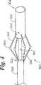
図1は、本発明の例示の実施例によるカテーテル100の斜視図である。このカテーテル100は、血管20内の易損性プラーク付着物22の位置のマッピングに使用できる。カテーテル100は細長いシャフト102を含む。このシャフトは先端104、基端(図1には示さず)、及び外面106を有する。カテーテル100は、複数のアーム108を更に含む。図1の実施例では、各アーム108の第1端122の近くにセンサ120が固定されている。各アーム108の第2端124は細長いシャフト102に固定されている。 FIG. 1 is a perspective view of a
アーム108は、好ましくは、延長位置及び引っ込め位置を有する。図1の実施例では、アーム108は延長位置で示してある。シース126が細長いシャフト102の周囲に配置されている。アーム108は、シース126を細長いシャフト102に沿って先端方向に前進させることによって強制的に引っ込め位置に置くことができる。好ましい実施例では、アーム108が延長位置にあるとき、各センサ120が血管20の内面24と接触する。 The
各センサ120は、温度センサ、超音波センサ、及び/又は電磁放射線センサを含む。好ましい実施例では、各センサ120は温度センサを含む。幾つかの用途に適した温度センサの例には、抵抗温度装置(RTD)、サーミスタ、熱電対、MEMS(超小型電子機械システム)、マイクロボロメータが含まれる。Each
血管20は複数の易損性プラーク付着物22を含む。これらの易損性プラーク付着物の各々は、比較的軟質な材料でできたコア部分26及びこのコアに被さったキャップ28を含む。カテーテル100を血管20を通して基端方向及び/又は先端方向に移動するとき、センサ120は、好ましくは血管100の内面24の様々な部分と接触する。 The
各センサ120からの信号の表示及び/又は記録は適当な機器を用いて行われる。カテーテル100を血管20を通して基端方向及び/又は先端方向に移動したときのこれらの信号の変化に着目する。センサ信号の変化は、カテーテル100の軸線方向位置と相関できる。この情報は、血管20内の任意の易損性プラーク付着物の位置を確かめるのに使用できる。 The display and / or recording of the signal from each
図2は血管20の横断面図である。図1のカテーテル100は、血管20の内腔30内に配置された状態で示してある。カテーテル100は、上文中に説明したように、血管20内の易損性プラーク付着物の位置のマッピングに使用できる。図2では、カテーテル100のアーム108が細長いシャフト102から半径方向に広がっていることがわかる。センサ120が各アーム108の第1端122の近くに固定されている。各アーム108の第2端124は細長いシャフト102に固定されている。血管20内でのプラーク付着物の各配向は、異なるセンサ120からの信号間の変化を観察することによって確認できる。例えば、易損性プラーク付着物22に近いセンサ120は、易損性プラーク付着物22に近くないセンサ120よりも高い温度の読みを提供する。 FIG. 2 is a cross-sectional view of the
図3は本発明の追加の例示の実施例によるカテーテル200の平面図である。カテーテル200は細長いシャフト202を有し、このシャフトは先端204、基端(図3には示さず)、及び外面206を有する。カテーテル200は複数のアーム208を更に含む。図3の実施例では、センサ220が各アーム208の第1端222に固定されている。各アーム208の中間部分226はカテーテル200の細長いシャフト202に固定されており、各アーム208の自由部分228は細長いシャフト202から遠ざかる方向に延びている。好ましい実施例では、アーム208の自由部分228は、カテーテル200を血管内に配置したときに血液の流れを安定化するように作用する。図3の実施例では、アーム208は延長位置で示してある。アーム208は、好ましくは、延長位置及び引っ込め位置を有する。 FIG. 3 is a plan view of a
図4は、本発明の更に別の例示の実施例によるカテーテル300の斜視図である。カテーテル300は、血管内の易損性プラーク付着物の位置のマッピングに使用できる。カテーテル300は、細長いシャフト302を有し、このシャフトは先端304、基端(図4には示さず)、及び外面306を有する。 FIG. 4 is a perspective view of a
シース326は、細長いシャフト302の一部の周囲に摺動自在に配置されている。複数のアーム308の第1端322はシース326に固定されている。各アーム308の第2端324はカテーテル300の本体部材330に固定されている。図4の実施例では、本体部材330が、先端304と近接して細長いシャフト302の周囲に配置されている。センサ320が第1端322と第2端324との間で各アーム308に固定されている。図4の実施例では、アーム308が延長位置で示してある。好ましい実施例では、アーム308は延長位置をとるように押圧される。アーム308は、シース326を細長いシャフト302に対して基端方向に移動することによって引っ込め位置に押圧できる。アーム308は、更に、シース326を細長いシャフト302に対して先端方向に移動することによって延長位置に押圧できる。好ましい実施例では、各センサ320は、アーム308が延長位置にあるとき、血管の内面と接触する。 The
各センサ320は、本発明の精神及び範囲から逸脱することなく、様々な種類のセンサを含むことができる。幾つかの用途に適したセンサの例には、圧力センサ、超音波センサ、電磁放射線センサ、及び温度センサが含まれる。好ましい実施例では、各センサ320は温度センサを含む。幾つかの用途に適した温度センサの例には、抵抗温度装置(RTD)、サーミスタ、熱電対、MEMS(超小型電子機械システム)、マイクロボロメータが含まれる。Each
図5は本発明の例示の実施例によるカテーテル400の斜視図である。カテーテル400は、更に、図5に示す延長位置をとるように押圧されたばね432を含むアーム408を有する。センサ420は、アーム408の第1端422の近くに固定される。アーム408の第2端424は細長いシャフト402に固定される。細長いシャフト402は、先端404、基端(図5には示さず)、及び外面406を有する。 FIG. 5 is a perspective view of a
図5では、カテーテル400は易損性プラーク付着物22を持つ血管20内に配置される。カテーテル400は血管20内の易損性プラーク付着物22の位置のマッピングに使用できる。好ましい実施例では、センサ420は、アーム408が図5に示す延長位置にあるとき、血管20の内面24と接触する。この好ましい実施例では、センサ420が計測した温度は、センサ420が易損性プラーク付着物22に近づくと上昇する。 In FIG. 5, the
図5に示す各易損性プラーク付着物は、比較的軟質な材料でできたコア部分26及びこのコアに被さったキャップ28を含む。カテーテル400を血管20を通して基端方向及び/又は先端方向に移動するとき、センサ420は、好ましくは血管20の内面24の様々な部分と接触する。 Each vulnerable plaque deposit shown in FIG. 5 includes a
センサ420からの信号は適当な機器を用いて表示され及び/又は記録される。カテーテル400を血管20を通して基端方向及び/又は先端方向に移動したときの信号の変化に着目する。これらの信号の変化は、カテーテル400の軸線方向位置と相関できる。センサ420からの信号の変化は、カテーテル400をその長さ方向軸線を中心として回転させたときにも検出される。これらの変化はカテーテル400の角度配向と相関できる。センサ420から集められた情報は、血管20内の任意の易損性プラーク付着物の位置を確かめるのに使用できる。 The signal from
図6は、図5のカテーテル400の部分断面図である。図6では、カテーテル400は、細長いシャフト402の周囲に配置されたシース426を含むことがわかる。図6の実施例では、シース426は細長いシャフト402に沿って先端方向に前進させてあり、そのため、カテーテル400のアーム408は引っ込め位置に配置される。図6では、カテーテル400はシース426と細長いシャフト402との間に配置されたケーブル434を含む。このケーブル434の先端は、好ましくはセンサ420に接続されており、ケーブル434の基端は、好ましくは、センサ420からの信号を表示及び/又は記録するようになった機器に接続されている。ケーブル434は、任意の数の導体を含むということは理解されるべきである。幾つかの用途では、導体の数をセンサ420に合わせて選択する。例えば、センサ420は、ケーブル434の二つの導体に接続された二つの接点を持つ熱電対を含む。 6 is a partial cross-sectional view of the
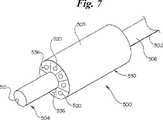
図7は、本発明の更に別の例示の実施例によるカテーテル500の斜視図である。このカテーテル500は細長いシャフト502を含む。このシャフトは、先端504、基端(図7には示さず)、及び外面506を有する。カテーテル500の本体部材530は細長いシャフト502の周囲に配置される。本体部材530は複数の流れチャンネル536を画成する。 FIG. 7 is a perspective view of a
図7の実施例では、センサ520が各流れチャンネル536内に配置されている。カテーテル500は、細長いシャフト502の先端504の近くに配置された基準センサ521を更に含む。センサ520及び521は、好ましくは、温度センサを含む。幾つかの用途に適した温度センサの例には、抵抗温度装置(RTD)、サーミスタ、及び熱電対が含まれる。 In the embodiment of FIG. 7, a
カテーテル500は、血管内の易損性プラーク付着物の位置のマッピングに使用できる。本体部材530の大きさは、好ましくは、本体部材530の外面505が血管の内面と近接して配置されるように定められる。この場合、血管の内面近くを流れる血液がチャンネルに流入する。センサ520はチャンネルを介して流れる血液の温度を測定する。易損性プラーク付着物上を流れる血液は、易損性プラーク付着物によって温められる。この血液の温度上昇をセンサ520を使用して観察し及び/又は記録する。 The
カテーテル500を血管を通して基端方向及び/又は先端方向に移動するとき、本体部材530の先端が血管の内面の様々な部分と近接する。センサからの信号の変化は、血管を通してカテーテル500を基端方向及び/又は先端方向に移動したときに発生し、これらの変化をカテーテル500の軸線方向位置と相関できる。この情報は、血管内の任意の易損性プラーク付着物の位置の軸線方向成分を確かめるのに使用できる。 As the
図7では、流れチャンネル536及びセンサ520が細長いシャフト502を中心として半径方向に配置されているということが理解されよう。血管内のプラーク付着物の位置の角度成分は、異なるセンサ520からの信号間の相違を観察することによって確かめることができる。例えば、易損性プラーク付着物の近くにあるセンサ520は、易損性プラーク付着物の近くにないセンサ520よりも高い温度を読み取る。 In FIG. 7, it will be appreciated that the
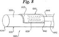
図8は、本発明の更に別の例示の実施例によるカテーテル600の斜視図である。カテーテル600は、血管内の易損性プラーク付着物の位置のマッピングに使用できる。カテーテル600は、細長いシャフト602を含む。このシャフトは、先端604、基端(図8には示さず)、及び外面606を有する。センサ620が細長いシャフト602の外面606に重なるように配置されている。図8の実施例では、センサ620は可撓性基材640及び導電路638を含む。この導電路638は第1導体642及び第2導体644に接続されている。好ましい実施例では、導電路638の電気抵抗は温度に従って変化する。更に、好ましい実施例では、第1導体642及び第2導体644は絶縁されている。第1導体642及び第2導体644は、例えば、細長いシャフト602に重ねた収縮チューブ層によって絶縁されている。図8の実施例では、センサ620は全体に円筒形の外面605を有する。好ましい実施例では、外面605の形状は、センサ620が血管内面と大部分の領域に亘って接触するように選択される。 FIG. 8 is a perspective view of a catheter 600 according to yet another exemplary embodiment of the present invention. The catheter 600 can be used to map the location of vulnerable plaque deposits within the blood vessel. Catheter 600 includes an elongate shaft 602. The shaft has a
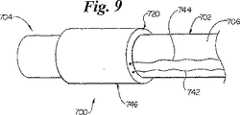
図9は、本発明の更に別の例示の実施例によるカテーテル700の斜視図である。カテーテル700は、血管内の易損性プラーク付着物の位置のマッピングに使用できる。カテーテル700は、細長いシャフト702を含む。このシャフトは、先端704、基端(図9には示さず)、及び外面706を有する。カテーテル700、細長いシャフト702の先端704の近くに配置されたセンサ720を更に含む。図9の実施例では、センサ720は全体に円筒形形状を有する。好ましい実施例では、本体746の形状は、センサが血管内面と大部分の領域に亘って接触するように選択される。第1導体742及び第2導体744がセンサ720に接続されている。好ましい実施例では、温度記録−表示機器が第1導体742及び第2導体744を介してセンサ720から信号を得る。 FIG. 9 is a perspective view of a catheter 700 in accordance with yet another exemplary embodiment of the present invention. The catheter 700 can be used to map the location of vulnerable plaque deposits within the blood vessel. Catheter 700 includes an elongate shaft 702. The shaft has a
図10は、本発明の更に別の例示の実施例によるカテーテル800の断面斜視図である。カテーテル800は、外面806を持つ細長いシャフト802を含む。カテーテル800のバルーン850が細長いシャフト802の周囲に配置されている。 FIG. 10 is a cross-sectional perspective view of a
カテーテル800は、更に、複数のカウル(cowl)854がバルーン850の周囲に配置された配列852を含む。カウルは、好ましくは、バルーン850に固定されている。各カウル854は、入口ポート856、出口ポート858、及びこれらのポート間を延びる流れチャンネル836を画成する。
センサ820(図10には示さず)は、好ましくは、各流れチャンネル836内に配置される。各センサ820は、好ましくは温度センサを含む。幾つかの用途に適した温度センサの例には、抵抗温度装置(RTD)、サーミスタ、及び熱電対が含まれる。 A sensor 820 (not shown in FIG. 10) is preferably disposed within each
バルーン850は、好ましくは、膨張状態及び収縮状態を有する。図10の実施例では、バルーン850は血管の外側に配置されており、膨張状態で示してある。好ましい実施例では、バルーン850は、バルーン850が膨張状態にあるときにカウル854が細長いシャフト802から半径方向に遠ざかる方向に押圧されるように形成されている。
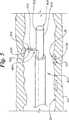
図11は、図10のカテーテル800の平断面図である。図11では、センサ820が各流れチャンネル836内に配置された状態で示してある。各流れチャンネル836は、好ましくはバルーン850に固定されたカウル854によって画成されている。バルーン850は細長いシャフト802の周囲に配置されている。 FIG. 11 is a plan sectional view of the
図11の実施例では、バルーン850は血管の外側に配置されており、膨張状態で示してある。バルーン850は、例えば、細長いシャフト802が画成する膨張内腔860及び膨張ポート862を通して流体を圧送することによって膨張できる。 In the embodiment of FIG. 11, the
バルーン850は、好ましくは、カテーテル800が血管内に配置された状態でバルーン850が膨張させたときにカウル854が血管内面に押し付けられるように形成されている。バルーン850は、好ましくは、バルーン850が膨張状態にある場合にカウル854の周囲の血流を妨げるように形成されている。 The
血管内面近くの血流は、好ましくは、カウル854が画成する流れチャンネル836を通って流れる。センサ820は、チャンネルを通って流れる血液の温度を計測するために使用できる。易損性プラーク付着物上を流れる血液は、易損性プラーク付着物によって温められる。この血液の温められた温度は、センサ820を使用して観察でき及び/又は記録できる。 Blood flow near the inner surface of the vessel preferably flows through a
図12は、本発明の更に別の例示の実施例によるカテーテル900の平断面図である。カテーテル900は、外面906を持つ細長いシャフト902を含む。カテーテル900のバルーン950は細長いシャフト902の周囲に配置される。 FIG. 12 is a cross-sectional plan view of a
カテーテル900は、更に、バルーン950の周囲に配置された複数のカウル954を含む配列952を有する。図12の実施例では、各カウルは、全体に楔状の断面形状を有する。各カウル954は、好ましくは、バルーン950に固定されている。
各カウル854は流れチャンネル936を画成する。センサ920が、好ましくは、各流れチャンネル936内に配置されている。各センサ920は、好ましくは、温度センサを含む。幾つかの用途に適した温度センサの例には、抵抗温度装置(RTD)、サーミスタ、及び熱電対が含まれる。 Each
バルーン950は、好ましくは、膨張状態及び収縮状態を有する。図12の実施例では、バルーン950は血管20内に配置されており、膨張状態で示してある。好ましい実施例では、バルーン950は、バルーン950が膨張状態にあるときにカウル954が細長いシャフト902から半径方向に遠ざかる方向に押圧されるように形成されている。図12では、カウル954がバルーン950によって血管20の内面24に押し付けられているのがわかる。バルーン950は、例えば、細長いシャフト902が画成する膨張内腔960及び膨張ポート962を通して流体を圧送することによって膨張できる。
バルーン950は、好ましくは、バルーン950が膨張状態にある場合にカウル954周囲の血流を阻止するように形成されている。血管20の内面24の近くを流れる血液は、好ましくは、カウル954が画成する流れチャンネル936に流入する。センサ920は、チャンネルを通って流れる血液の温度を計測するのに使用できる。易損性プラーク付着物上を流れる血液は、易損性プラーク付着物によって温められる。この血液の高められた温度は、センサ920を使用して観察でき及び/又は記録できる。
本発明の好ましい実施例を説明したが、更に別の実施例を実施でき、特許請求の範囲内で使用できるということは当業者には容易に理解されよう。本願に含まれる本発明の多くの利点を以上に説明した。しかしながら、本開示は、多くの点に関し、単なる例示であるということは理解されよう。詳細について、特に部品の形状、大きさ、及び構成を本発明の範囲を越えることなく変更できる。勿論、本発明の範囲は、特許請求の範囲で表現した用語で定義される。 While the preferred embodiment of the present invention has been described, it will be readily appreciated by those skilled in the art that additional embodiments can be implemented and used within the scope of the claims. The many advantages of the invention contained herein have been described above. However, it will be understood that this disclosure is merely exemplary in many respects. In particular, the shape, size and configuration of the parts can be changed without exceeding the scope of the invention. Of course, the scope of the present invention is defined by the terms expressed in the claims.
1 マイクロプロセッサ
2 記録−読取装置
3 収集トラック
4 ごみ収集容器
1 Microprocessor 2 Record-reader 3 Collection truck 4 Garbage collection container
Claims (31)
Translated fromJapanese基端及び先端を持つ細長いシャフト、
前記細長いシャフトの前記先端に固定された少なくとも一つのカウル、
前記少なくとも一つのカウルは、入口ポート、出口ポート、及びこれらのポート間を延びる流体の流れチャンネルを画成し、及び
前記少なくとも一つのカウルによって画成された前記流れチャンネル内に配置された少なくとも一つの温度センサを有する、カテーテル。In a catheter for mapping vulnerable plaque deposits in blood vessels,
An elongated shaft having a proximal end and a distal end,
At least one cowl secured to the tip of the elongated shaft;
The at least one cowl defines an inlet port, an outlet port, and a fluid flow channel extending between the ports, and at least one disposed within the flow channel defined by the at least one cowl. Catheter with two temperature sensors.
前記少なくとも一つのカウルは、前記流れチャンネルを通過する血液の温度が前記カテーテルの前記先端近くの血管の内面の温度を表すように形成されている、カテーテル。The catheter of claim 1, wherein the at least one temperature sensor is adapted to measure the temperature of blood passing through the flow channel,
The catheter wherein the at least one cowl is configured such that the temperature of blood passing through the flow channel represents the temperature of the inner surface of a blood vessel near the tip of the catheter.
基端及び先端を持つ細長いシャフト、
前記細長いシャフトの前記先端近くの周囲に放射状に配置された複数のカウル、
前記カウルの各々は、入口ポート、出口ポート、及びこれらのポート間を延びる流体の流れチャンネルを画成し、及び
前記流れチャンネルの各々内に配置された温度センサを有する、カテーテル。In a catheter for mapping vulnerable plaque deposits in blood vessels,
An elongated shaft having a proximal end and a distal end,
A plurality of cowls arrangedradially around the tip of the elongated shaft;
Each of the cowls defines an inlet port, an outlet port, and a fluid flow channel extending between the ports, and a temperature sensor disposed within each of the flow channels.
基端及び先端を持つ細長いシャフト、
前記細長いシャフトの前記先端近くの周囲に放射状に配置されたカウルのアレイ、
前記カウルの各々は、入口ポート、出口ポート、及びこれらのポート間を延びる流体の流れチャンネルを画成し、
前記流れチャンネルの各々内に配置された温度センサ、及び
前記カウルのアレイを半径方向に膨張するための手段を有する、カテーテル。In a catheter for mapping vulnerable plaque deposits in blood vessels,
An elongated shaft having a proximal end and a distal end,
The elongate shaft of the tip near the cowl of the array disposedradially around,
Each of the cowls defines an inlet port, an outlet port, and a fluid flow channel extending between the ports;
Having a means for expansion temperature sensor disposed within each of said flow channels, and the array of cowlsradially catheter.
Applications Claiming Priority (2)
| Application Number | Priority Date | Filing Date | Title |
|---|---|---|---|
| US09/782,502US6514214B2 (en) | 2001-02-13 | 2001-02-13 | Intravascular temperature sensor |
| PCT/US2002/003712WO2002069795A1 (en) | 2001-02-13 | 2002-02-07 | Intravascular temperature sensor |
Publications (3)
| Publication Number | Publication Date |
|---|---|
| JP2004528878A JP2004528878A (en) | 2004-09-24 |
| JP2004528878A5 JP2004528878A5 (en) | 2008-05-01 |
| JP4124654B2true JP4124654B2 (en) | 2008-07-23 |
Family
ID=25126252
Family Applications (1)
| Application Number | Title | Priority Date | Filing Date |
|---|---|---|---|
| JP2002568981AExpired - Fee RelatedJP4124654B2 (en) | 2001-02-13 | 2002-02-07 | Intravascular temperature sensor |
Country Status (8)
| Country | Link |
|---|---|
| US (2) | US6514214B2 (en) |
| EP (1) | EP1359840B1 (en) |
| JP (1) | JP4124654B2 (en) |
| AT (1) | ATE297686T1 (en) |
| CA (1) | CA2438687C (en) |
| DE (1) | DE60204663T2 (en) |
| ES (1) | ES2240695T3 (en) |
| WO (1) | WO2002069795A1 (en) |
Families Citing this family (73)
| Publication number | Priority date | Publication date | Assignee | Title |
|---|---|---|---|---|
| US6673098B1 (en)* | 1998-08-24 | 2004-01-06 | Radiant Medical, Inc. | Disposable cassette for intravascular heat exchange catheter |
| US7426409B2 (en)* | 1999-06-25 | 2008-09-16 | Board Of Regents, The University Of Texas System | Method and apparatus for detecting vulnerable atherosclerotic plaque |
| US20030120171A1 (en)* | 2000-09-08 | 2003-06-26 | Leonidas Diamantopoulos | Vasular temperature measuring device and process for measuring vascular temperature |
| US20030149368A1 (en)* | 2000-10-24 | 2003-08-07 | Hennemann Willard W. | Method and apparatus for locating and detecting vascular plaque via impedence and conductivity measurements, and for cryogenically passivating vascular plaque and inhibiting vascular plaque progression and rupture |
| US6575623B2 (en)* | 2000-11-10 | 2003-06-10 | Cardiostream, Inc. | Guide wire having extendable contact sensors for measuring temperature of vessel walls |
| US6514214B2 (en)* | 2001-02-13 | 2003-02-04 | Scimed Life Systems, Inc. | Intravascular temperature sensor |
| US6811561B2 (en)* | 2001-11-15 | 2004-11-02 | Cordis Neurovascular, Inc. | Small diameter deployment system with improved headpiece |
| WO2003051194A1 (en)* | 2001-12-18 | 2003-06-26 | 3Cpm Company | Endoscopic measurement of myoelectrical activity from intra-abdominal organs |
| US20030187319A1 (en)* | 2002-03-29 | 2003-10-02 | Olympus Optical Co., Ltd. | Sentinel lymph node detecting apparatus, and method thereof |
| US20040073132A1 (en)* | 2002-05-07 | 2004-04-15 | Tracy Maahs | Systems and methods for detecting vulnerable plaque |
| US6866638B2 (en)* | 2002-08-12 | 2005-03-15 | Radiant Medical, Inc. | Temperature sensing system with retrograde sensor |
| US7077812B2 (en)* | 2002-11-22 | 2006-07-18 | The Board Regents Of The University System | Apparatus and method for palpographic characterization of vulnerable plaque and other biological tissue |
| CA2508800A1 (en) | 2002-12-11 | 2004-06-24 | Proteus Biomedical, Inc. | Method and system for monitoring and treating hemodynamic parameters |
| US7200439B2 (en) | 2003-01-24 | 2007-04-03 | Proteus Biomedical, Inc. | Method and apparatus for enhancing cardiac pacing |
| WO2004066814A2 (en) | 2003-01-24 | 2004-08-12 | Proteus Biomedical Inc. | Method and system for remote hemodynamic monitoring |
| JP4465349B2 (en) | 2003-01-24 | 2010-05-19 | プロテウス バイオメディカル インコーポレイテッド | Method and system for measuring cardiac parameters |
| JP3966468B2 (en)* | 2003-02-12 | 2007-08-29 | 学校法人日本大学 | Apparatus for measuring elasticity characteristics of living tissue |
| US20040167467A1 (en)* | 2003-02-21 | 2004-08-26 | Kent Harrison | Delivering cooled fluid to sites inside the body |
| US7153299B1 (en) | 2003-02-24 | 2006-12-26 | Maxwell Sensors Inc. | Optical apparatus for detecting and treating vulnerable plaque |
| US7297154B2 (en)* | 2003-02-24 | 2007-11-20 | Maxwell Sensors Inc. | Optical apparatus for detecting and treating vulnerable plaque |
| US7004911B1 (en) | 2003-02-24 | 2006-02-28 | Hosheng Tu | Optical thermal mapping for detecting vulnerable plaque |
| GB0304439D0 (en)* | 2003-02-27 | 2003-04-02 | Imp College Innovations Ltd | A device |
| US20040243022A1 (en)* | 2003-04-29 | 2004-12-02 | Medtronic Vascular, Inc. | Method and system of detecting vulnerable plaque by sensing motion of thin fibrous cap |
| US7303530B2 (en)* | 2003-05-22 | 2007-12-04 | Siemens Medical Solutions Usa, Inc. | Transducer arrays with an integrated sensor and methods of use |
| WO2005000091A2 (en)* | 2003-05-28 | 2005-01-06 | Payvar, Saeed | Method and apparatus for detecting ischemia |
| US6932776B2 (en)* | 2003-06-02 | 2005-08-23 | Meridian Medicalssystems, Llc | Method and apparatus for detecting and treating vulnerable plaques |
| WO2005046443A2 (en)* | 2003-11-07 | 2005-05-26 | Georgia Tech Research Corporation | Combination catheter devices, methods, and systems |
| US7326195B2 (en)* | 2003-11-18 | 2008-02-05 | Boston Scientific Scimed, Inc. | Targeted cooling of tissue within a body |
| EP1713399A4 (en)* | 2004-02-06 | 2010-08-11 | Georgia Tech Res Inst | Cmut devices and fabrication methods |
| WO2005084284A2 (en)* | 2004-02-27 | 2005-09-15 | Georgia Tech Research Corporation | Multiple element electrode cmut devices and fabrication methods |
| US7646133B2 (en)* | 2004-02-27 | 2010-01-12 | Georgia Tech Research Corporation | Asymmetric membrane cMUT devices and fabrication methods |
| EP1761998A4 (en)* | 2004-02-27 | 2011-05-11 | Georgia Tech Res Inst | Harmonic cmut devices and fabrication methods |
| JP4554967B2 (en)* | 2004-03-25 | 2010-09-29 | テルモ株式会社 | Ultrasonic catheter and diagnostic imaging apparatus |
| US20060025840A1 (en)* | 2004-08-02 | 2006-02-02 | Martin Willard | Cooling tissue inside the body |
| WO2006029090A2 (en)* | 2004-09-02 | 2006-03-16 | Proteus Biomedical, Inc. | Methods and apparatus for tissue activation and monitoring |
| US20060178857A1 (en)* | 2005-02-10 | 2006-08-10 | Barajas Leandro G | Quasi-redundant smart sensing topology |
| EP1871470A4 (en) | 2005-03-31 | 2011-06-01 | Proteus Biomedical Inc | Automated optimization of multi-electrode pacing for cardiac resynchronization |
| WO2007021804A2 (en) | 2005-08-12 | 2007-02-22 | Proteus Biomedical, Inc. | Evaluation of depolarization wave conduction velocity |
| WO2007026354A1 (en)* | 2005-08-29 | 2007-03-08 | Galil Medical Ltd. | Multiple sensor device for measuring tissue temperature during thermal treatment |
| GB0519259D0 (en)* | 2005-09-21 | 2005-10-26 | Imp College Innovations Ltd | A device |
| US20070208257A1 (en)* | 2006-03-03 | 2007-09-06 | Furnish Simon M | Lateral Viewing Optical Catheters |
| ATE480206T1 (en) | 2006-03-03 | 2010-09-15 | Prescient Medical Inc | ENDOLUMINAL PROSTHESIS FOR THE TREATMENT OF SENSITIVE PLAQUE |
| WO2007103235A2 (en)* | 2006-03-03 | 2007-09-13 | Prescient Medical, Inc. | Optical imaging balloon catheters |
| US20070225795A1 (en)* | 2006-03-24 | 2007-09-27 | Juan Granada | Composite vascular prosthesis |
| US20080140182A1 (en)* | 2006-04-28 | 2008-06-12 | Patricia Scheller | Composite endoluminal prostheses for treating vulnerable plaque |
| US7717244B2 (en)* | 2006-08-15 | 2010-05-18 | Sonnax Industries, Inc. | Replacement torque converter cover assembly |
| US20110021924A1 (en)* | 2007-02-09 | 2011-01-27 | Shriram Sethuraman | Intravascular photoacoustic and utrasound echo imaging |
| EP2160217A1 (en)* | 2007-06-08 | 2010-03-10 | Prescient Medical, Inc. | Optical catheter configurations combining raman spectroscopy with optical fiber-based low coherence reflectometry |
| EP2190389A1 (en) | 2007-08-01 | 2010-06-02 | Prescient Medical, Inc. | Expandable prostheses for treating atherosclerotic lesions including vulnerable plaques |
| US20090088651A1 (en)* | 2007-09-28 | 2009-04-02 | Allan Charles Shuros | Method and apparatus to perform transvascular hemodynamic sensing |
| US8473069B2 (en) | 2008-02-28 | 2013-06-25 | Proteus Digital Health, Inc. | Integrated circuit implementation and fault control system, device, and method |
| WO2009117523A2 (en)* | 2008-03-18 | 2009-09-24 | Circa Medical, Llc | Large surface area temperature sensing device |
| US20090275815A1 (en)* | 2008-03-21 | 2009-11-05 | Nova Biomedical Corporation | Temperature-compensated in-vivo sensor |
| US20090240121A1 (en)* | 2008-03-21 | 2009-09-24 | Nova Biomedical Corporation | Intravascular sensor and insertion set combination |
| US20090287044A1 (en)* | 2008-05-15 | 2009-11-19 | Olympus Medical Systems Corp. | Endoscopic apparatus |
| WO2010006265A2 (en)* | 2008-07-10 | 2010-01-14 | Texas Heart Institute | Method and system for temperature analysis to provide an early marker of congestive heart failure progress that precedes a patient's symptoms |
| US20100113906A1 (en)* | 2008-11-06 | 2010-05-06 | Prescient Medical, Inc. | Hybrid basket catheters |
| US8366719B2 (en) | 2009-03-18 | 2013-02-05 | Integrated Spinal Concepts, Inc. | Image-guided minimal-step placement of screw into bone |
| WO2010126503A1 (en) | 2009-04-29 | 2010-11-04 | Proteus Biomedical, Inc. | Methods and apparatus for leads for implantable devices |
| WO2011011736A2 (en) | 2009-07-23 | 2011-01-27 | Proteus Biomedical, Inc. | Solid-state thin film capacitor |
| US8718770B2 (en) | 2010-10-21 | 2014-05-06 | Medtronic, Inc. | Capture threshold measurement for selection of pacing vector |
| US8355784B2 (en) | 2011-05-13 | 2013-01-15 | Medtronic, Inc. | Dynamic representation of multipolar leads in a programmer interface |
| JP2014184134A (en)* | 2013-02-25 | 2014-10-02 | Inter Noba Kk | Catheter for monitoring biological environment |
| US9192345B2 (en)* | 2013-03-11 | 2015-11-24 | Mark A. D'Andrea | Radiation devices and methods |
| WO2017118986A2 (en)* | 2016-01-07 | 2017-07-13 | The Medical Research, Infrastructure and Health Services Fund of the Tel Aviv Medical Center | Coronary sinus electrophysiology measurements device and methods |
| US10086213B2 (en) | 2015-04-23 | 2018-10-02 | Mark A. D'Andrea | Mobile gynecological balloon devices and methods |
| JP6812423B2 (en)* | 2015-09-22 | 2021-01-13 | ジョンソン・アンド・ジョンソン・コンシューマー・インコーポレイテッドJohnson & Johnson Consumer Inc. | Vaginal ring sensor |
| US10876902B2 (en)* | 2018-01-10 | 2020-12-29 | Biosense Webster (Israel) Ltd. | Position-controlled thermocouple |
| KR20220124749A (en)* | 2020-01-07 | 2022-09-14 | 바드 액세스 시스템즈, 인크. | DIAGNOSTIC SYSTEMS AND METHODS INCLUDING TEMPERATURE-SENSING VASCULAR DEVICES |
| EP4284237A1 (en)* | 2021-01-27 | 2023-12-06 | Octogone Medical | System for predicting vascular plaque rupture or detachment that could lead to a stroke and/or for predicting vascular thrombosis |
| FR3119089B1 (en)* | 2021-01-27 | 2024-05-24 | Octogone Medical | System for predicting vascular plaque rupture or separation that could lead to stroke |
| US20240180491A1 (en)* | 2022-12-02 | 2024-06-06 | Bard Access Systems, Inc. | Cut-to-Length Sensing Catheters and Methods Thereof |
| WO2024188680A1 (en)* | 2023-03-14 | 2024-09-19 | Koninklijke Philips N.V. | Intravascular mechanical shape and stiffness sensor |
Family Cites Families (145)
| Publication number | Priority date | Publication date | Assignee | Title |
|---|---|---|---|---|
| US1355846A (en)* | 1920-02-06 | 1920-10-19 | David A Rannells | Medical appliance |
| US2547758A (en)* | 1949-01-05 | 1951-04-03 | Wilmer B Keeling | Instrument for treating the male urethra |
| US2632443A (en)* | 1949-04-18 | 1953-03-24 | Eleanor P Lesher | Surgical dressing |
| US2682873A (en)* | 1952-07-30 | 1954-07-06 | Johnson & Johnson | General purpose protective dressing |
| US2969057A (en)* | 1957-11-04 | 1961-01-24 | Brady Co W H | Nematodic swab |
| US3273395A (en) | 1963-08-05 | 1966-09-20 | Barnes Eng Co | Automatic ambient temperature compensation for a medical thermometer |
| US3367332A (en)* | 1965-08-27 | 1968-02-06 | Gen Electric | Product and process for establishing a sterile area of skin |
| US3520300A (en)* | 1967-03-15 | 1970-07-14 | Amp Inc | Surgical sponge and suction device |
| US3682180A (en)* | 1970-06-08 | 1972-08-08 | Coilform Co Inc | Drain clip for surgical drain |
| BE789293Q (en)* | 1970-12-07 | 1973-01-15 | Parke Davis & Co | MEDICO-SURGICAL DRESSING FOR BURNS AND SIMILAR LESIONS |
| US3866599A (en) | 1972-01-21 | 1975-02-18 | Univ Washington | Fiberoptic catheter |
| US3913568A (en) | 1973-01-22 | 1975-10-21 | American Optical Corp | Nasopharyngoscope |
| US3826254A (en)* | 1973-02-26 | 1974-07-30 | Verco Ind | Needle or catheter retaining appliance |
| US4005605A (en) | 1974-07-22 | 1977-02-01 | Mikron Instrument Company, Inc. | Remote reading infrared thermometer |
| DE2527706A1 (en)* | 1975-06-21 | 1976-12-30 | Hanfried Dr Med Weigand | DEVICE FOR THE INTRODUCTION OF CONTRAST AGENTS INTO AN ARTIFICIAL INTESTINAL OUTLET |
| NL7710909A (en)* | 1976-10-08 | 1978-04-11 | Smith & Nephew | COMPOSITE STRAPS. |
| GB1562244A (en)* | 1976-11-11 | 1980-03-05 | Lock P M | Wound dressing materials |
| US4080970A (en)* | 1976-11-17 | 1978-03-28 | Miller Thomas J | Post-operative combination dressing and internal drain tube with external shield and tube connector |
| US4139004A (en)* | 1977-02-17 | 1979-02-13 | Gonzalez Jr Harry | Bandage apparatus for treating burns |
| US4165748A (en)* | 1977-11-07 | 1979-08-28 | Johnson Melissa C | Catheter tube holder |
| SE414994B (en)* | 1978-11-28 | 1980-09-01 | Landstingens Inkopscentral | VENKATETERFORBAND |
| GB2047543B (en)* | 1978-12-06 | 1983-04-20 | Svedman Paul | Device for treating tissues for example skin |
| US4284079A (en)* | 1979-06-28 | 1981-08-18 | Adair Edwin Lloyd | Method for applying a male incontinence device |
| US4261363A (en)* | 1979-11-09 | 1981-04-14 | C. R. Bard, Inc. | Retention clips for body fluid drains |
| US4569348A (en)* | 1980-02-22 | 1986-02-11 | Velcro Usa Inc. | Catheter tube holder strap |
| WO1981002516A1 (en)* | 1980-03-11 | 1981-09-17 | E Schmid | Cushion for holding an element of grafted skin |
| US4297995A (en)* | 1980-06-03 | 1981-11-03 | Key Pharmaceuticals, Inc. | Bandage containing attachment post |
| USRE32204E (en) | 1980-06-09 | 1986-07-15 | Mansfield Scientific, Inc. | Electrode assembly for temporary pacing and heart measurements |
| US4333468A (en)* | 1980-08-18 | 1982-06-08 | Geist Robert W | Mesentery tube holder apparatus |
| US4392853A (en)* | 1981-03-16 | 1983-07-12 | Rudolph Muto | Sterile assembly for protecting and fastening an indwelling device |
| US4373519A (en)* | 1981-06-26 | 1983-02-15 | Minnesota Mining And Manufacturing Company | Composite wound dressing |
| US4392858A (en)* | 1981-07-16 | 1983-07-12 | Sherwood Medical Company | Wound drainage device |
| US4419097A (en)* | 1981-07-31 | 1983-12-06 | Rexar Industries, Inc. | Attachment for catheter tube |
| SE429197B (en)* | 1981-10-14 | 1983-08-22 | Frese Nielsen | SAR TREATMENT DEVICE |
| DE3146266A1 (en)* | 1981-11-21 | 1983-06-01 | B. Braun Melsungen Ag, 3508 Melsungen | COMBINED DEVICE FOR A MEDICAL SUCTION DRAINAGE |
| US4551139A (en)* | 1982-02-08 | 1985-11-05 | Marion Laboratories, Inc. | Method and apparatus for burn wound treatment |
| US4475909A (en)* | 1982-05-06 | 1984-10-09 | Eisenberg Melvin I | Male urinary device and method for applying the device |
| US5542915A (en) | 1992-08-12 | 1996-08-06 | Vidamed, Inc. | Thermal mapping catheter with ultrasound probe |
| US4540412A (en)* | 1983-07-14 | 1985-09-10 | The Kendall Company | Device for moist heat therapy |
| US4543100A (en)* | 1983-11-01 | 1985-09-24 | Brodsky Stuart A | Catheter and drain tube retainer |
| US4525374A (en)* | 1984-02-27 | 1985-06-25 | Manresa, Inc. | Treating hydrophobic filters to render them hydrophilic |
| US4897081A (en)* | 1984-05-25 | 1990-01-30 | Thermedics Inc. | Percutaneous access device |
| US4872450A (en)* | 1984-08-17 | 1989-10-10 | Austad Eric D | Wound dressing and method of forming same |
| US4602642A (en) | 1984-10-23 | 1986-07-29 | Intelligent Medical Systems, Inc. | Method and apparatus for measuring internal body temperature utilizing infrared emissions |
| US4790324A (en) | 1984-10-23 | 1988-12-13 | Intelligent Medical Systems, Inc. | Method and apparatus for measuring internal body temperature utilizing infrared emissions |
| US4655754A (en)* | 1984-11-09 | 1987-04-07 | Stryker Corporation | Vacuum wound drainage system and lipids baffle therefor |
| US4605399A (en)* | 1984-12-04 | 1986-08-12 | Complex, Inc. | Transdermal infusion device |
| US5318024A (en) | 1985-03-22 | 1994-06-07 | Massachusetts Institute Of Technology | Laser endoscope for spectroscopic imaging |
| US4776334A (en) | 1985-03-22 | 1988-10-11 | Stanford University | Catheter for treatment of tumors |
| US4797840A (en) | 1985-04-17 | 1989-01-10 | Thermoscan Inc. | Infrared electronic thermometer and method for measuring temperature |
| US5037397A (en)* | 1985-05-03 | 1991-08-06 | Medical Distributors, Inc. | Universal clamp |
| US4640688A (en)* | 1985-08-23 | 1987-02-03 | Mentor Corporation | Urine collection catheter |
| US4710165A (en)* | 1985-09-16 | 1987-12-01 | Mcneil Charles B | Wearable, variable rate suction/collection device |
| US4699147A (en) | 1985-09-25 | 1987-10-13 | Cordis Corporation | Intraventricular multielectrode cardial mapping probe and method for using same |
| US4758220A (en)* | 1985-09-26 | 1988-07-19 | Alcon Laboratories, Inc. | Surgical cassette proximity sensing and latching apparatus |
| US4752141A (en) | 1985-10-25 | 1988-06-21 | Luxtron Corporation | Fiberoptic sensing of temperature and/or other physical parameters |
| US4784149A (en) | 1986-01-13 | 1988-11-15 | Optical Sensors, Inc. | Infrared thermometer with automatic calibration |
| US4733659A (en)* | 1986-01-17 | 1988-03-29 | Seton Company | Foam bandage |
| US5000185A (en) | 1986-02-28 | 1991-03-19 | Cardiovascular Imaging Systems, Inc. | Method for intravascular two-dimensional ultrasonography and recanalization |
| US4794931A (en) | 1986-02-28 | 1989-01-03 | Cardiovascular Imaging Systems, Inc. | Catheter apparatus, system and method for intravascular two-dimensional ultrasonography |
| JPS62207435A (en) | 1986-03-07 | 1987-09-11 | テルモ株式会社 | Catheter for measuring cardiac output |
| US4838883A (en)* | 1986-03-07 | 1989-06-13 | Nissho Corporation | Urine-collecting device |
| JPS62281965A (en)* | 1986-05-29 | 1987-12-07 | テルモ株式会社 | Catheter and catheter fixing member |
| GB8621884D0 (en)* | 1986-09-11 | 1986-10-15 | Bard Ltd | Catheter applicator |
| US4743232A (en)* | 1986-10-06 | 1988-05-10 | The Clinipad Corporation | Package assembly for plastic film bandage |
| DE3634569A1 (en)* | 1986-10-10 | 1988-04-21 | Sachse Hans E | CONDOM CATHETER, A URINE TUBE CATHETER FOR PREVENTING RISING INFECTIONS |
| JPS63135179A (en)* | 1986-11-26 | 1988-06-07 | 立花 俊郎 | Subcataneous drug administration set |
| GB8706116D0 (en)* | 1987-03-14 | 1987-04-15 | Smith & Nephew Ass | Adhesive dressings |
| DE3718139C1 (en) | 1987-05-29 | 1988-12-08 | Strahlen Umweltforsch Gmbh | Cardiac catheter |
| US4787888A (en)* | 1987-06-01 | 1988-11-29 | University Of Connecticut | Disposable piezoelectric polymer bandage for percutaneous delivery of drugs and method for such percutaneous delivery (a) |
| US4863449A (en)* | 1987-07-06 | 1989-09-05 | Hollister Incorporated | Adhesive-lined elastic condom cathether |
| US4777955A (en) | 1987-11-02 | 1988-10-18 | Cordis Corporation | Left ventricle mapping probe |
| US5176663A (en)* | 1987-12-02 | 1993-01-05 | Pal Svedman | Dressing having pad with compressibility limiting elements |
| US4826949A (en)* | 1987-12-22 | 1989-05-02 | Basf Corporation | High shrinkage polyester fibers and method of preparation |
| US4906240A (en)* | 1988-02-01 | 1990-03-06 | Matrix Medica, Inc. | Adhesive-faced porous absorbent sheet and method of making same |
| US4985019A (en)* | 1988-03-11 | 1991-01-15 | Michelson Gary K | X-ray marker |
| WO1989011311A1 (en) | 1988-05-18 | 1989-11-30 | Kasevich Associates, Inc. | Microwave balloon angioplasty |
| US4919654A (en)* | 1988-08-03 | 1990-04-24 | Kalt Medical Corporation | IV clamp with membrane |
| US5059596A (en)* | 1989-01-16 | 1991-10-22 | Roussel Uclaf | Azabicyclo compounds |
| US5046501A (en) | 1989-01-18 | 1991-09-10 | Wayne State University | Atherosclerotic identification |
| US5100396A (en)* | 1989-04-03 | 1992-03-31 | Zamierowski David S | Fluidic connection system and method |
| US5261893A (en)* | 1989-04-03 | 1993-11-16 | Zamierowski David S | Fastening system and method |
| US4969880A (en)* | 1989-04-03 | 1990-11-13 | Zamierowski David S | Wound dressing and treatment method |
| US5527293A (en)* | 1989-04-03 | 1996-06-18 | Kinetic Concepts, Inc. | Fastening system and method |
| US4986671A (en) | 1989-04-12 | 1991-01-22 | Luxtron Corporation | Three-parameter optical fiber sensor and system |
| US5358494A (en)* | 1989-07-11 | 1994-10-25 | Svedman Paul | Irrigation dressing |
| JP2719671B2 (en)* | 1989-07-11 | 1998-02-25 | 日本ゼオン株式会社 | Wound dressing |
| US5232453A (en)* | 1989-07-14 | 1993-08-03 | E. R. Squibb & Sons, Inc. | Catheter holder |
| US5057105A (en) | 1989-08-28 | 1991-10-15 | The University Of Kansas Med Center | Hot tip catheter assembly |
| US5109859A (en) | 1989-10-04 | 1992-05-05 | Beth Israel Hospital Association | Ultrasound guided laser angioplasty |
| US5134994A (en)* | 1990-02-12 | 1992-08-04 | Say Sam L | Field aspirator in a soft pack with externally mounted container |
| US5092858A (en)* | 1990-03-20 | 1992-03-03 | Becton, Dickinson And Company | Liquid gelling agent distributor device |
| US4995398A (en) | 1990-04-30 | 1991-02-26 | Turnidge Patrick A | Coronary angiography imaging system |
| US5558093A (en) | 1990-05-18 | 1996-09-24 | Cardiovascular Imaging Systems, Inc. | Guidewire with imaging capability |
| US5275594A (en) | 1990-11-09 | 1994-01-04 | C. R. Bard, Inc. | Angioplasty system having means for identification of atherosclerotic plaque |
| US5149331A (en)* | 1991-05-03 | 1992-09-22 | Ariel Ferdman | Method and device for wound closure |
| US5682899A (en) | 1991-05-16 | 1997-11-04 | Ami-Med Corporation | Apparatus and method for continuous cardiac output monitoring |
| US5174299A (en) | 1991-08-12 | 1992-12-29 | Cardiac Pacemakers, Inc. | Thermocouple-based blood flow sensor |
| US5278100A (en)* | 1991-11-08 | 1994-01-11 | Micron Technology, Inc. | Chemical vapor deposition technique for depositing titanium silicide on semiconductor wafers |
| US5645081A (en)* | 1991-11-14 | 1997-07-08 | Wake Forest University | Method of treating tissue damage and apparatus for same |
| US5279550A (en)* | 1991-12-19 | 1994-01-18 | Gish Biomedical, Inc. | Orthopedic autotransfusion system |
| US5237996A (en) | 1992-02-11 | 1993-08-24 | Waldman Lewis K | Endocardial electrical mapping catheter |
| JPH05228098A (en) | 1992-02-20 | 1993-09-07 | Asahi Optical Co Ltd | Thermoendoscope |
| US5217456A (en) | 1992-02-24 | 1993-06-08 | Pdt Cardiovascular, Inc. | Device and method for intra-vascular optical radial imaging |
| US5167613A (en)* | 1992-03-23 | 1992-12-01 | The Kendall Company | Composite vented wound dressing |
| FR2690617B1 (en)* | 1992-04-29 | 1994-06-24 | Cbh Textile | TRANSPARENT ADHESIVE DRESSING. |
| US5336178A (en) | 1992-11-02 | 1994-08-09 | Localmed, Inc. | Intravascular catheter with infusion array |
| US5373849A (en) | 1993-01-19 | 1994-12-20 | Cardiovascular Imaging Systems, Inc. | Forward viewing imaging catheter |
| US5279565A (en) | 1993-02-03 | 1994-01-18 | Localmed, Inc. | Intravascular treatment apparatus and method |
| US5344415A (en)* | 1993-06-15 | 1994-09-06 | Deroyal Industries, Inc. | Sterile system for dressing vascular access site |
| US5437651A (en)* | 1993-09-01 | 1995-08-01 | Research Medical, Inc. | Medical suction apparatus |
| US5656643A (en)* | 1993-11-08 | 1997-08-12 | Rhone-Poulenc Rorer Pharmaceuticals Inc. | Bis mono-and bicyclic aryl and heteroaryl compounds which inhibit EGF and/or PDGF receptor tyrosine kinase |
| JP3403233B2 (en) | 1994-01-20 | 2003-05-06 | テルモ株式会社 | Balloon catheter |
| US5549584A (en)* | 1994-02-14 | 1996-08-27 | The Kendall Company | Apparatus for removing fluid from a wound |
| US5556375A (en)* | 1994-06-16 | 1996-09-17 | Hercules Incorporated | Wound dressing having a fenestrated base layer |
| US5607388A (en)* | 1994-06-16 | 1997-03-04 | Hercules Incorporated | Multi-purpose wound dressing |
| EP0768842A4 (en) | 1994-06-27 | 1998-05-13 | Ep Technologies | Systems and methods for sensing temperature within the body |
| US5664270A (en)* | 1994-07-19 | 1997-09-09 | Kinetic Concepts, Inc. | Patient interface system |
| US5623940A (en) | 1994-08-02 | 1997-04-29 | S.L.T. Japan Co., Ltd. | Catheter apparatus with a sensor |
| US5810802A (en) | 1994-08-08 | 1998-09-22 | E.P. Technologies, Inc. | Systems and methods for controlling tissue ablation using multiple temperature sensing elements |
| US6176842B1 (en)* | 1995-03-08 | 2001-01-23 | Ekos Corporation | Ultrasound assembly for use with light activated drugs |
| US5606974A (en) | 1995-05-02 | 1997-03-04 | Heart Rhythm Technologies, Inc. | Catheter having ultrasonic device |
| US5733739A (en) | 1995-06-07 | 1998-03-31 | Inphocyte, Inc. | System and method for diagnosis of disease by infrared analysis of human tissues and cells |
| US6053937A (en)* | 1995-08-15 | 2000-04-25 | Rita Medical Systems, Inc. | Multiple electrode ablation apparatus and method with cooling element |
| US5660380A (en) | 1995-08-15 | 1997-08-26 | W. L. Gore & Associates, Inc. | Vacuum fixture and method for dimensioning and manipulating materials |
| WO1997010748A1 (en) | 1995-09-20 | 1997-03-27 | Texas Heart Institute | Detecting thermal discrepancies in vessel walls |
| US5755760A (en) | 1996-03-11 | 1998-05-26 | Medtronic, Inc. | Deflectable catheter |
| US20010049517A1 (en) | 1997-03-06 | 2001-12-06 | Gholam-Reza Zadno-Azizi | Method for containing and removing occlusions in the carotid arteries |
| US6245026B1 (en)* | 1996-07-29 | 2001-06-12 | Farallon Medsystems, Inc. | Thermography catheter |
| US5924997A (en) | 1996-07-29 | 1999-07-20 | Campbell; Thomas Henderson | Catheter and method for the thermal mapping of hot spots in vascular lesions of the human body |
| US5792070A (en)* | 1996-08-30 | 1998-08-11 | Urologix, Inc. | Rectal thermosensing unit |
| US5871449A (en) | 1996-12-27 | 1999-02-16 | Brown; David Lloyd | Device and method for locating inflamed plaque in an artery |
| US5849028A (en) | 1997-05-16 | 1998-12-15 | Irvine Biomedical, Inc. | Catheter and method for radiofrequency ablation of cardiac tissue |
| US6135116A (en)* | 1997-07-28 | 2000-10-24 | Kci Licensing, Inc. | Therapeutic method for treating ulcers |
| GB9719520D0 (en)* | 1997-09-12 | 1997-11-19 | Kci Medical Ltd | Surgical drape and suction heads for wound treatment |
| US6071267A (en)* | 1998-02-06 | 2000-06-06 | Kinetic Concepts, Inc. | Medical patient fluid management interface system and method |
| US6488643B1 (en)* | 1998-10-08 | 2002-12-03 | Kci Licensing, Inc. | Wound healing foot wrap |
| US7799004B2 (en)* | 2001-03-05 | 2010-09-21 | Kci Licensing, Inc. | Negative pressure wound treatment apparatus and infection identification system and method |
| US6856821B2 (en)* | 2000-05-26 | 2005-02-15 | Kci Licensing, Inc. | System for combined transcutaneous blood gas monitoring and vacuum assisted wound closure |
| US20010007940A1 (en)* | 1999-06-21 | 2001-07-12 | Hosheng Tu | Medical device having ultrasound imaging and therapeutic means |
| US6579243B2 (en)* | 2000-03-02 | 2003-06-17 | Scimed Life Systems, Inc. | Catheter with thermal sensor for detection of vulnerable plaque |
| US6712771B2 (en)* | 2000-06-16 | 2004-03-30 | Accumed Systems, Inc. | Temperature sensing catheter |
| JP2004508074A (en)* | 2000-08-24 | 2004-03-18 | ボルケーノ セラピューティックス, インコーポレイテッド | Thermographic catheter with flexible circuit temperature sensor |
| US6514214B2 (en)* | 2001-02-13 | 2003-02-04 | Scimed Life Systems, Inc. | Intravascular temperature sensor |
| US6540705B2 (en)* | 2001-02-22 | 2003-04-01 | Core Products International, Inc. | Ankle brace providing upper and lower ankle adjustment |
- 2001
- 2001-02-13USUS09/782,502patent/US6514214B2/ennot_activeExpired - Lifetime
- 2002
- 2002-02-07JPJP2002568981Apatent/JP4124654B2/ennot_activeExpired - Fee Related
- 2002-02-07ESES02704384Tpatent/ES2240695T3/ennot_activeExpired - Lifetime
- 2002-02-07DEDE60204663Tpatent/DE60204663T2/ennot_activeExpired - Lifetime
- 2002-02-07EPEP02704384Apatent/EP1359840B1/ennot_activeExpired - Lifetime
- 2002-02-07WOPCT/US2002/003712patent/WO2002069795A1/enactiveIP Right Grant
- 2002-02-07ATAT02704384Tpatent/ATE297686T1/ennot_activeIP Right Cessation
- 2002-02-07CACA2438687Apatent/CA2438687C/ennot_activeExpired - Fee Related
- 2002-12-16USUS10/320,221patent/US20030125637A1/ennot_activeAbandoned
Also Published As
| Publication number | Publication date |
|---|---|
| DE60204663D1 (en) | 2005-07-21 |
| US20030125637A1 (en) | 2003-07-03 |
| WO2002069795A1 (en) | 2002-09-12 |
| DE60204663T2 (en) | 2006-05-18 |
| EP1359840B1 (en) | 2005-06-15 |
| ATE297686T1 (en) | 2005-07-15 |
| EP1359840A1 (en) | 2003-11-12 |
| ES2240695T3 (en) | 2005-10-16 |
| CA2438687A1 (en) | 2002-09-12 |
| JP2004528878A (en) | 2004-09-24 |
| US20020111560A1 (en) | 2002-08-15 |
| CA2438687C (en) | 2011-04-26 |
| US6514214B2 (en) | 2003-02-04 |
Similar Documents
| Publication | Publication Date | Title |
|---|---|---|
| JP4124654B2 (en) | Intravascular temperature sensor | |
| EP1280452B1 (en) | Catheter with thermal sensor for detection of vulnerable plaque | |
| US6536949B1 (en) | Catheter for thermal evaluation of arteriosclerotic plaque | |
| US20030013986A1 (en) | Device for sensing temperature profile of a hollow body organ | |
| US6575623B2 (en) | Guide wire having extendable contact sensors for measuring temperature of vessel walls | |
| US6245026B1 (en) | Thermography catheter | |
| US20020077564A1 (en) | Thermography catheter | |
| US20040176699A1 (en) | Thermography catheter with improved wall contact | |
| JP4049675B2 (en) | Method and apparatus for detecting vulnerable plaque | |
| WO2002089871A2 (en) | Thermography catheter | |
| US20020048310A1 (en) | Catheter for thermal and ultrasound evaluation of arteriosclerotic plaque | |
| JPH0332640A (en) | Pressure-monitoring catheter used together with monorail system | |
| JP2008535630A (en) | Imaging guidewire for forward observation | |
| EP1608263B1 (en) | Blood-flow-occluding, temperature-sensing catheters | |
| US20030114761A1 (en) | System for locating inflamed plaque in a vessel | |
| US20030233052A1 (en) | Catheter with thermal sensor for detection of vulnerable plaque | |
| CN112245771A (en) | Moving a guidewire in a brain lumen | |
| US20030013987A1 (en) | Expandable device for mapping temperature profile of a hollow body organ | |
| WO2003039619A2 (en) | Catheter and process for the temperature measurement of the vascular wall |
Legal Events
| Date | Code | Title | Description |
|---|---|---|---|
| A621 | Written request for application examination | Free format text:JAPANESE INTERMEDIATE CODE: A621 Effective date:20050207 | |
| A131 | Notification of reasons for refusal | Free format text:JAPANESE INTERMEDIATE CODE: A131 Effective date:20070112 | |
| A601 | Written request for extension of time | Free format text:JAPANESE INTERMEDIATE CODE: A601 Effective date:20070115 | |
| A602 | Written permission of extension of time | Free format text:JAPANESE INTERMEDIATE CODE: A602 Effective date:20070122 | |
| A524 | Written submission of copy of amendment under article 19 pct | Free format text:JAPANESE INTERMEDIATE CODE: A524 Effective date:20070712 | |
| A521 | Request for written amendment filed | Free format text:JAPANESE INTERMEDIATE CODE: A821 Effective date:20070712 | |
| A131 | Notification of reasons for refusal | Free format text:JAPANESE INTERMEDIATE CODE: A131 Effective date:20080226 | |
| A524 | Written submission of copy of amendment under article 19 pct | Free format text:JAPANESE INTERMEDIATE CODE: A524 Effective date:20080312 | |
| TRDD | Decision of grant or rejection written | ||
| A01 | Written decision to grant a patent or to grant a registration (utility model) | Free format text:JAPANESE INTERMEDIATE CODE: A01 Effective date:20080407 | |
| A01 | Written decision to grant a patent or to grant a registration (utility model) | Free format text:JAPANESE INTERMEDIATE CODE: A01 | |
| A521 | Request for written amendment filed | Free format text:JAPANESE INTERMEDIATE CODE: A821 Effective date:20080312 | |
| A61 | First payment of annual fees (during grant procedure) | Free format text:JAPANESE INTERMEDIATE CODE: A61 Effective date:20080502 | |
| R150 | Certificate of patent or registration of utility model | Free format text:JAPANESE INTERMEDIATE CODE: R150 | |
| FPAY | Renewal fee payment (event date is renewal date of database) | Free format text:PAYMENT UNTIL: 20110516 Year of fee payment:3 | |
| FPAY | Renewal fee payment (event date is renewal date of database) | Free format text:PAYMENT UNTIL: 20120516 Year of fee payment:4 | |
| FPAY | Renewal fee payment (event date is renewal date of database) | Free format text:PAYMENT UNTIL: 20130516 Year of fee payment:5 | |
| FPAY | Renewal fee payment (event date is renewal date of database) | Free format text:PAYMENT UNTIL: 20130516 Year of fee payment:5 | |
| R250 | Receipt of annual fees | Free format text:JAPANESE INTERMEDIATE CODE: R250 | |
| LAPS | Cancellation because of no payment of annual fees |