JP4124647B2 - Electrosurgical system - Google Patents
Electrosurgical systemDownload PDFInfo
- Publication number
- JP4124647B2 JP4124647B2JP2002538842AJP2002538842AJP4124647B2JP 4124647 B2JP4124647 B2JP 4124647B2JP 2002538842 AJP2002538842 AJP 2002538842AJP 2002538842 AJP2002538842 AJP 2002538842AJP 4124647 B2JP4124647 B2JP 4124647B2
- Authority
- JP
- Japan
- Prior art keywords
- generator
- tissue
- pulse
- power
- pulses
- Prior art date
- Legal status (The legal status is an assumption and is not a legal conclusion. Google has not performed a legal analysis and makes no representation as to the accuracy of the status listed.)
- Expired - Lifetime
Links
- 238000011282treatmentMethods0.000claimsabstractdescription41
- 230000001965increasing effectEffects0.000claimsabstractdescription20
- 238000009833condensationMethods0.000claimsabstractdescription6
- 230000004044responseEffects0.000claimsdescription11
- 230000007423decreaseEffects0.000claimsdescription8
- 238000010336energy treatmentMethods0.000claimsdescription3
- 230000015271coagulationEffects0.000abstractdescription23
- 238000005345coagulationMethods0.000abstractdescription23
- 230000005494condensationEffects0.000abstractdescription4
- 210000001519tissueAnatomy0.000description202
- 230000000694effectsEffects0.000description41
- 238000012546transferMethods0.000description34
- 238000000034methodMethods0.000description17
- 230000008901benefitEffects0.000description13
- 230000015572biosynthetic processEffects0.000description11
- 210000004204blood vesselAnatomy0.000description10
- 238000013461designMethods0.000description10
- 238000010438heat treatmentMethods0.000description10
- 238000001035dryingMethods0.000description9
- 239000000463materialSubstances0.000description9
- 230000002459sustained effectEffects0.000description8
- 239000003792electrolyteSubstances0.000description7
- 230000002792vascularEffects0.000description7
- 238000010586diagramMethods0.000description6
- 230000006870functionEffects0.000description6
- 238000010521absorption reactionMethods0.000description5
- 230000005540biological transmissionEffects0.000description5
- 239000008280bloodSubstances0.000description5
- 210000004369bloodAnatomy0.000description5
- 238000005520cutting processMethods0.000description5
- 238000002674endoscopic surgeryMethods0.000description5
- 239000012530fluidSubstances0.000description5
- 230000007704transitionEffects0.000description5
- 208000032843HemorrhageDiseases0.000description4
- 208000034158bleedingDiseases0.000description4
- 230000000740bleeding effectEffects0.000description4
- 238000009835boilingMethods0.000description4
- 239000003990capacitorSubstances0.000description4
- 230000008859changeEffects0.000description4
- 230000003247decreasing effectEffects0.000description4
- 238000012544monitoring processMethods0.000description4
- 230000009467reductionEffects0.000description4
- 230000011218segmentationEffects0.000description4
- 229910001220stainless steelInorganic materials0.000description4
- 239000010935stainless steelSubstances0.000description4
- 230000001225therapeutic effectEffects0.000description4
- 230000008016vaporizationEffects0.000description4
- 208000031737Tissue AdhesionsDiseases0.000description3
- 230000004888barrier functionEffects0.000description3
- 230000007012clinical effectEffects0.000description3
- 230000006378damageEffects0.000description3
- 238000002224dissectionMethods0.000description3
- 238000009826distributionMethods0.000description3
- 230000007246mechanismEffects0.000description3
- 238000007789sealingMethods0.000description3
- 238000007711solidificationMethods0.000description3
- 230000008023solidificationEffects0.000description3
- 238000009834vaporizationMethods0.000description3
- 210000005166vasculatureAnatomy0.000description3
- 238000013459approachMethods0.000description2
- 238000003763carbonizationMethods0.000description2
- 239000011248coating agentSubstances0.000description2
- 238000000576coating methodMethods0.000description2
- 230000002301combined effectEffects0.000description2
- 239000004020conductorSubstances0.000description2
- 210000002808connective tissueAnatomy0.000description2
- 230000008878couplingEffects0.000description2
- 238000010168coupling processMethods0.000description2
- 238000005859coupling reactionMethods0.000description2
- 238000002474experimental methodMethods0.000description2
- 230000023597hemostasisEffects0.000description2
- 238000009802hysterectomyMethods0.000description2
- 238000009413insulationMethods0.000description2
- 210000003101oviductAnatomy0.000description2
- 230000000737periodic effectEffects0.000description2
- 230000021715photosynthesis, light harvestingEffects0.000description2
- 238000001356surgical procedureMethods0.000description2
- 230000003685thermal hair damageEffects0.000description2
- 238000009827uniform distributionMethods0.000description2
- 229910000831SteelInorganic materials0.000description1
- 238000002679ablationMethods0.000description1
- 238000009825accumulationMethods0.000description1
- 238000007486appendectomyMethods0.000description1
- 230000000903blocking effectEffects0.000description1
- 230000009172burstingEffects0.000description1
- 238000007675cardiac surgeryMethods0.000description1
- 230000001364causal effectEffects0.000description1
- 230000006835compressionEffects0.000description1
- 238000007906compressionMethods0.000description1
- 238000001514detection methodMethods0.000description1
- 239000002360explosiveSubstances0.000description1
- 210000003722extracellular fluidAnatomy0.000description1
- 230000008713feedback mechanismEffects0.000description1
- 230000008014freezingEffects0.000description1
- 238000007710freezingMethods0.000description1
- 230000002496gastric effectEffects0.000description1
- 210000004300gastroepiploic arteryAnatomy0.000description1
- 235000013531ginNutrition0.000description1
- PCHJSUWPFVWCPO-UHFFFAOYSA-NgoldChemical compound[Au]PCHJSUWPFVWCPO-UHFFFAOYSA-N0.000description1
- 229910052737goldInorganic materials0.000description1
- 239000010931goldSubstances0.000description1
- 230000017525heat dissipationEffects0.000description1
- 230000020169heat generationEffects0.000description1
- 230000001939inductive effectEffects0.000description1
- 230000003993interactionEffects0.000description1
- 210000000936intestineAnatomy0.000description1
- 210000002977intracellular fluidAnatomy0.000description1
- 230000004807localizationEffects0.000description1
- 210000001349mammary arteryAnatomy0.000description1
- 239000002184metalSubstances0.000description1
- 229910052751metalInorganic materials0.000description1
- 230000007935neutral effectEffects0.000description1
- 239000000615nonconductorSubstances0.000description1
- 238000001208nuclear magnetic resonance pulse sequenceMethods0.000description1
- 230000008520organizationEffects0.000description1
- 230000001575pathological effectEffects0.000description1
- 230000000149penetrating effectEffects0.000description1
- 230000035515penetrationEffects0.000description1
- 239000006223plastic coatingSubstances0.000description1
- 230000002265preventionEffects0.000description1
- 230000008569processEffects0.000description1
- 230000002250progressing effectEffects0.000description1
- 230000002035prolonged effectEffects0.000description1
- 210000003752saphenous veinAnatomy0.000description1
- 239000007787solidSubstances0.000description1
- 230000007480spreadingEffects0.000description1
- 238000003892spreadingMethods0.000description1
- 239000010959steelSubstances0.000description1
- 230000002123temporal effectEffects0.000description1
- 238000012360testing methodMethods0.000description1
- 238000007669thermal treatmentMethods0.000description1
- 230000000451tissue damageEffects0.000description1
- 231100000827tissue damageToxicity0.000description1
- 210000004291uterusAnatomy0.000description1
- 238000012800visualizationMethods0.000description1
- XLYOFNOQVPJJNP-UHFFFAOYSA-NwaterChemical compoundOXLYOFNOQVPJJNP-UHFFFAOYSA-N0.000description1
Images


Classifications
- A—HUMAN NECESSITIES
- A61—MEDICAL OR VETERINARY SCIENCE; HYGIENE
- A61B—DIAGNOSIS; SURGERY; IDENTIFICATION
- A61B18/00—Surgical instruments, devices or methods for transferring non-mechanical forms of energy to or from the body
- A61B18/04—Surgical instruments, devices or methods for transferring non-mechanical forms of energy to or from the body by heating
- A61B18/12—Surgical instruments, devices or methods for transferring non-mechanical forms of energy to or from the body by heating by passing a current through the tissue to be heated, e.g. high-frequency current
- A61B18/14—Probes or electrodes therefor
- A61B18/1442—Probes having pivoting end effectors, e.g. forceps
- A61B18/1445—Probes having pivoting end effectors, e.g. forceps at the distal end of a shaft, e.g. forceps or scissors at the end of a rigid rod
- A—HUMAN NECESSITIES
- A61—MEDICAL OR VETERINARY SCIENCE; HYGIENE
- A61B—DIAGNOSIS; SURGERY; IDENTIFICATION
- A61B18/00—Surgical instruments, devices or methods for transferring non-mechanical forms of energy to or from the body
- A61B18/04—Surgical instruments, devices or methods for transferring non-mechanical forms of energy to or from the body by heating
- A61B18/12—Surgical instruments, devices or methods for transferring non-mechanical forms of energy to or from the body by heating by passing a current through the tissue to be heated, e.g. high-frequency current
- A61B18/1206—Generators therefor
- A61B18/1233—Generators therefor with circuits for assuring patient safety
- A—HUMAN NECESSITIES
- A61—MEDICAL OR VETERINARY SCIENCE; HYGIENE
- A61B—DIAGNOSIS; SURGERY; IDENTIFICATION
- A61B18/00—Surgical instruments, devices or methods for transferring non-mechanical forms of energy to or from the body
- A61B2018/00636—Sensing and controlling the application of energy
- A61B2018/00666—Sensing and controlling the application of energy using a threshold value
- A—HUMAN NECESSITIES
- A61—MEDICAL OR VETERINARY SCIENCE; HYGIENE
- A61B—DIAGNOSIS; SURGERY; IDENTIFICATION
- A61B18/00—Surgical instruments, devices or methods for transferring non-mechanical forms of energy to or from the body
- A61B2018/00636—Sensing and controlling the application of energy
- A61B2018/00696—Controlled or regulated parameters
- A61B2018/00702—Power or energy
- A—HUMAN NECESSITIES
- A61—MEDICAL OR VETERINARY SCIENCE; HYGIENE
- A61B—DIAGNOSIS; SURGERY; IDENTIFICATION
- A61B18/00—Surgical instruments, devices or methods for transferring non-mechanical forms of energy to or from the body
- A61B2018/00636—Sensing and controlling the application of energy
- A61B2018/00696—Controlled or regulated parameters
- A61B2018/00726—Duty cycle
- A—HUMAN NECESSITIES
- A61—MEDICAL OR VETERINARY SCIENCE; HYGIENE
- A61B—DIAGNOSIS; SURGERY; IDENTIFICATION
- A61B18/00—Surgical instruments, devices or methods for transferring non-mechanical forms of energy to or from the body
- A61B2018/00636—Sensing and controlling the application of energy
- A61B2018/00773—Sensed parameters
- A61B2018/00779—Power or energy
- A—HUMAN NECESSITIES
- A61—MEDICAL OR VETERINARY SCIENCE; HYGIENE
- A61B—DIAGNOSIS; SURGERY; IDENTIFICATION
- A61B18/00—Surgical instruments, devices or methods for transferring non-mechanical forms of energy to or from the body
- A61B2018/00636—Sensing and controlling the application of energy
- A61B2018/00773—Sensed parameters
- A61B2018/00875—Resistance or impedance
Landscapes
- Health & Medical Sciences (AREA)
- Surgery (AREA)
- Engineering & Computer Science (AREA)
- Life Sciences & Earth Sciences (AREA)
- Biomedical Technology (AREA)
- Otolaryngology (AREA)
- Nuclear Medicine, Radiotherapy & Molecular Imaging (AREA)
- Plasma & Fusion (AREA)
- Physics & Mathematics (AREA)
- Heart & Thoracic Surgery (AREA)
- Medical Informatics (AREA)
- Molecular Biology (AREA)
- Animal Behavior & Ethology (AREA)
- General Health & Medical Sciences (AREA)
- Public Health (AREA)
- Veterinary Medicine (AREA)
- Surgical Instruments (AREA)
Abstract
Description
Translated fromJapanese【0001】
この発明は、電気外科用機器、電気外科用方法、および電気外科用システムに関する。より特定的には、この発明は二極式の無線周波数(r. f.)電気外科用出力を提供し、その特徴は、内視鏡手術中に行なわれるかもしれないような血管構造のより迅速で、より制御された、より有効な封鎖などをもたらす。
【0002】
身体組織の切断および凝固を行なうのにr. f. 電流を用いることは長年にわたって公知であり、電気外科の広範な説明の下に置かれる。r. f. 電流を組織へ伝達する2つの手法が、現在一般に用いられている.
これらのうちの第1の手法である単極式の電気外科は、患者の身体の外部表面上に置かれた活性(組織処置)電極および遠隔のリターン(または中性)電極(またはパッド)の使用を伴う。電流は、活性電極から、標的部位を通り、標的部位とリターン電極との間の経路に存在する他の組織を通って流れる。この構成は、部位外火傷、言換えれば、標的部位以外の部位で起こる組織の火傷の可能性をもたらす。医学文献は、火傷を引起こす他の機器へのr. f. 電流の容量結合、絶縁不良による組織への直接結合、患者の身体を通る電流経路に沿った火傷、およびリターンパッドの適用部位で起こる火傷の多数の例への言及を含んでいる。
【0003】
第2の手法は二極式の電気外科として公知である。二極式の電気外科は、活性電極およびリターン電極の双方をともに接近させて、通常は外科用機器の先端に組込むことによって、電流の流れを標的部位に局所的に封じ込めることを伴う。この構成は、身体を通って流れる電流が電気回路を完成させる必要性を回避し、このため部位外火傷の危険を排除する。したがって、二極式の電気外科の使用は、安全性が最大の懸念事項である場合、特に、r. f. 電流を極めて重要な構造近傍に印加する場合、または内視鏡手術中など視覚化が制限されている場合に好ましい。その結果、内視鏡手術中の血管の二極式の凝固または封鎖は、金属クリップ、ステープルまたは結紮を用いる血管の機械的封鎖に対し、費用効率が高く使いやすい代替となってきている。
【0004】
一般に、二極式の凝固に用いられる電気外科用機器は1対の鉗子からなり、鉗子の各あご部はr. f. 電極である。鉗子のサイズ、したがって回路に含まれる組織の量に依存して、印加される電力は通常、1W〜50W間で変動し得る。従来の二極式のr. f. 電気外科を用いる際に遭遇される最も重大な問題は、鉗子間に把持された組織全体にわたるエネルギの分布に関する。これらの制限の結果、外科医は、理論的には完全な封鎖を確実にし、次に血管を分割する際の出血の危険を低下させるために、血管を有効に封鎖するのに必要な分を十分上回るr. f. エネルギを通常印加する。これは隣接する組織への凝固の過度の広がりにつながり、鉗子のあご部が組織に付着するようになる危険を高める。この付着は、鉗子を解除する際に凝固した組織が引き裂かれるようになるほど十分深刻な場合があり、血管の未処置区域の損傷および著しい出血につながる。
【0005】
二極式のr. f. 電気外科用発生器の凝固出力についての業界規格は、10Ω〜1000Ω間の特定された負荷曲線で、最大電力が約50W−70Wである。この電力は一般に、正弦波などの持続的な、波高因子の低い波形として伝達される。そのような発生器からのピーク電圧は、ピーク間で1000Vもの高さとなり得る。しかし、電圧がより低いと、凝固する際に組織を付着または炭化させる傾向が減少する、ということが現在認識されている。近年の設計では、ピーク間で400Vまでの最大電圧が、現在、より一般に用いられている。この種の発生器の低インピーダンス整合能力は制限されており、最大電流伝達は通常、全力で約1.5Aである。
【0006】
これらの進歩にもかかわらず、どの公知の二極式のr. f. 発生器も、組織インピーダンスの変動、鉗子あご部の幾何学的形状、導電性流体の存在、および組織圧縮による、組織内の差エネルギ吸収の問題を克服していない。その結果、凝固は不可避的に乾燥点に達し、そこでは、鉗子あご部の温度の付随的な上昇とともに、流体が沸騰してなくなるにつれて組織が乾ききる。組織付着の原因は、70−80℃を上回る電極温度の上昇である。これは使用中に遭遇される変数のためにより起こりやすくなるので、一般に血管茎において遭遇されるように、処置されるべき血管がインピーダンスの高い脂肪層内に含まれる場合に特に起こりやすい。脂肪層は、インピーダンスがより低い血管構造を有効に絶縁し、そのため、完全な封鎖と過度の印加とが双方ともより起こりやすくなる。
【0007】
これらの理由のため、二極式のr. f. 電気外科用エネルギを、組織を凝固させるための改良された方法で伝達することが望ましいであろう。使用中に遭遇される変数にほとんど関係なく、処置されるべき組織全体にわたってエネルギのより制御された吸収を提供することが特に望ましく、そのため、脂肪茎内の不完全な血管封鎖、組織付着、および過度の熱マージンの問題が克服され得る。内視鏡手術中に、米国特許第5,445,638号に開示されるもののような機器を介して、改良された二極式のr. f. 電気外科用出力を提供することが、さらに望ましいであろう。
【0008】
電気外科用機器は、付着の問題を解決するために提案されてきた。米国特許第3,685,518号、第4,492,231号、および第6,059,783号はすべて、十分な熱容量の電極を構成することによって、および/または熱を放散する熱伝導性材料の使用によって熱を除去する方法を記載している。米国特許第5,885,281号は、付着の効果を最小限に抑えるコーティングの使用を記載している。
【0009】
インピーダンスおよび温度に基づいたr. f. 発生器制御は、米国特許第5,496,312号に記載されている。我々の米国特許第5,423,810号は、組織インピーダンスに従った発振器搬送周波数の変動に基づく、インピーダンスに制御された二極式の焼灼出力を記載している。
【0010】
米国特許第6,033,399号(ジンズ(Gines))は、組織が十分に乾燥するまで、電力レベルが、処置されている把持された組織の変動するインピーダンスに応答して、低い値と高い値との間を周期的に変動するような態様で、外科用把持具に出力電力を印加可能な電気外科用発生器を開示している。
【0011】
これらの手法は、付着を防止する点で、ほどほどの成功を収めてきた。
【0012】
この発明の第1の局面によれば、電気外科用発生器は、r. f. エネルギの源と、二極式の電気外科用機器への接続のための、およびr. f. エネルギを源から機器へ伝達するための少なくとも1対の出力端子と、源用のパルシング回路とを含み、パルシング回路および源は、出力端子間の抵抗負荷に、信号の連続する処置パルス間の周期が少なくとも100msであることによって、および予め定められたマーク対スペース比によって特徴付けられた処置パルスの連続の形をした、振幅変調されたr. f. 信号を出力端子で伝達するよう構成されており、発生器は、少なくとも100Wのピーク電力を、20Ω〜250Ωの範囲の任意の抵抗負荷に伝達可能であるよう構成されている。
好ましくは、1:1未満のパルスのマーク対スペース比で、振幅変調の深さは実質的に100%である。
【0013】
抵抗負荷が発生器の出力端子間に結合されている場合、数々の連続するパルスの各々中のr. f. 電流は、実効値で少なくとも3アンペアに達していてもよい。
【0014】
通常、パルス繰返し数は5Hz未満またはそれに等しく、好ましくは1Hz未満であり、r. f. 源およびパルシング回路は、r. f. エネルギの処置パルスの連続を出力端子で発生させるよう構成されており、連続するそのようなパルス間の周期は300msまたはそれよりも長い。
【0015】
パルス繰返し数が1Hz未満である場合、パルシング回路およびr. f. 源は、r. f. エネルギの処置パルスの連続を出力端子で発生させるよう構成されており、連続するそのようなパルス間の周期は1秒またはそれよりも長い。
【0016】
好ましい発生器では、回路は、抵抗負荷が出力端子間に接続されている場合、振幅変調されたr. f. 信号のピーク電圧が200ボルト未満のままとなるよう構成されており、抵抗負荷が10Ω〜1kΩの範囲にある場合、各パルスにおいて伝達されるr. f. エネルギは少なくとも2ジュールである。
【0017】
この発明の第2の局面によれば、電気外科用発生器は、無線周波数(r.f.)エネルギの源と、二極式の電気外科用機器への接続のための、およびr.f.エネルギを機器へ伝達するための少なくとも1対の出力端子と、源用のパルシング回路と、出力端子に関連する少なくとも1つの電気的パラメータをモニタするための手段を含む制御回路とを含み、制御回路、パルシング回路、および源の構成は、出力端子が抵抗負荷に接続されている状態で、制御回路が源に、少なくとも初期期間には予め定められた初期パルスデューティサイクルを有する処置パルスの連続であり、次の期間には異なる特性を有する振幅変調r.f.電力信号を、負荷に伝達させるようになっており、初期期間から次の期間への遷移は、少なくとも1つのモニタされたパラメータに応答して制御回路により制御されており、発生器は、少なくとも100Wのピーク電力を、20Ω〜250Ωの範囲の任意の抵抗負荷に伝達可能であるよう構成されている。
制御回路は、r.f.電力信号に、次の期間中、持続的なエネルギ伝達または初期期間中よりもよりほぼ持続的なエネルギ伝達を提供させるよう構成されていてもよいが、より一般的には、r.f.電力信号は、上述の次の期間の少なくとも一部の間中に初期パルスデューティサイクルよりも大きい第2の予め定められたパルスデューティサイクルを有している振幅変調信号として伝達される。一般に、次の期間中のピーク電力は、初期期間中よりも低い。特定の好ましい一実施例では、パルスデューティサイクルは、初期期間中には第1の予め定められたパルスデューティサイクルに固定され、次の期間中には第2のより大きな予め定められたパルスデューティサイクルに固定され、次の期間は初期期間に直接続いている。一代替例として、r.f.電力信号のパルスデューティサイクルは、2つ以上のステップで増加してもよく、そのため、たとえば、信号は、予め定められた低く一定のパルスデューティサイクルで始まり、次に、第1のパルスデューティサイクルよりも大きく、ピーク電力がより低いパルスデューティサイクルに切替えられ、その後、さらにより高いパルスデューティサイクルおよびさらに低いピーク電力に切替えられる。さらなる一代替例として、パルスデューティサイクルは、ピーク電圧を漸進的に減少させることを伴って、漸進的に増加されてもよい。
【0018】
r. f. 電力信号を用いて行なわれる処置サイクルが、持続波(c. w.)信号が次に続くパルス信号であろうと、パルスデューティサイクルが段階的にまたは漸進的に増加される信号であろうと、ピーク電力は、平均伝達電力が処置サイクルの大部分にわたってほぼ一定のままであるように、対応して減少されてもよく、サイクルは初期期間で始まり、r. f. 電力信号が終了されたときに終わる。
【0019】
初期期間から次の期間への遷移は、抵抗負荷に伝達されたエネルギを表わすフィードバック信号、または負荷の抵抗またはインピーダンスを表わすフィードバック信号に応答して制御されてもよい。フィードバック信号は出力電圧(ピーク電圧または実効値電圧)を感知することによって得られてもよく、遷移は、たとえば予め定められた値を超える出力電圧を示す感知回路からの感知信号に応答して制御される。予め定められた値は、約150V〜250Vのピークであってもよい。
【0020】
電源切換周波数で動作する切換モード電源を有する発生器の場合、出力電圧感知回路は、出力電圧が予め定められた値を超す場合に電源のパルシングが停止されるように、電源に結合されてもよい。出力電圧はその場合、電源の駆動パルスをモニタすることによって、たとえばパルスを数えることによって感知されてもよい。次に計数出力を用いてr. f. 電力信号のパルスデューティサイクルおよび/またはピーク電力を制御してもよい。
【0023】
この発明はまた、一体型電気外科用発生器および機器システムも含み、発生器は上に言及された特徴を有し、機器は1対の鉗子を含む。
【0024】
この発明のさらなる局面によれば、一体型電気外科用発生器および機器システムが提供され、機器は発生器に取外し可能に接続可能で、機器識別素子を含んでいる。発生器は上述の発生器の特徴のいずれかを有していてもよく、識別素子を感知するための感知回路を含んでおり、発生器のパルシング回路は、感知回路によって感知されるような識別素子に応答して、信号パルスのマーク対スペース比を自動的に調節するよう構成されている。システムは、発生器に選択的に接続可能で、それぞれの識別素子を含む複数の二極式の電気外科用鉗子機器を含んでいてもよい。機器は(機器電極によって規定される)異なる組織接触区域を有し、それぞれの識別素子は、発生器の感知回路および/またはパルシング回路と組み合わされた場合、マーク対スペース比が、比較的大きい組織接触区域を規定する電極を有する機器についてはより低い値に、比較的小さい組織接触区域を規定する電極を有する機器についてはより高い値に設定されるよう、選択される。比較的大きい組織接触区域を有する機器が選択されている場合、識別素子、感知回路、およびパルシング回路は、好ましくは、パルス周波数を減少させるよう選択され構成される。
【0025】
二極式の電気外科用機器の電極間の組織の電気外科的な凝固は、このため、r.f.エネルギの制御されたバーストを電極間に印加することによって達成され、各バーストは組織内に少なくとも1つの気泡を形成するのに十分高い電力であり、連続するバースト間の時間持続期間は、その泡または各泡の再凝結を可能とするのに十分長い。
【0026】
上に概説された特徴は大抵、二極式の機器の電極間に高電力でr. f. エネルギを印加することによって、組織を抵抗の正の温度係数(PTCR)材料として挙動させる。PTCR効果は「電流占有」の傾向を利用することによりもたらされ、それにより、抵抗の負の温度係数(NTCR)のため、組織の領域へのr. f. エネルギの印加が局所的な温度上昇を引起こし、それが次に電流密度の局所化を引起こし、r. f. 電流は、たとえば組織の薄い部分が1対の鉗子として形成された電極間に把持されている場合特に、最高温度の区域に集中される傾向にある。PTCR効果は、印加される電圧が実質的に300ボルト未満のピークであると仮定すると実質的に電気絶縁体である気泡が形成される組織に、十分な電力を伝達することによって達成される。ここで、r. f. 電流は気泡のまわりに経路を見つけなければならないため、材料は全体としてインピーダンスの増加を呈し、有効にPTCR特性を与える。このためエネルギの放散はより均一に分布され、その結果、熱凝固が標的部位全体にわたって起こる。
【0027】
注目すべき特徴は、最高電流密度により誘発された最高温度は、機器電極間の組織の表面上というよりはむしろ組織内で起こるということである。気体が一旦形成されると、気泡の縁のまわりに最高電流密度が起こり、それぞれのパルスバーストの終りまで気泡のさらなる加熱および膨張を引起こす。なぜなら、泡の膨張は、最高電流密度の区域が組織表面の下の組織の未処置領域に押し込まれるようなものだからである。これは鉗子あご部の局所化された加熱の危険を低下させ、したがって組織付着の危険を低下させる。
【0028】
これらの効果は、標的組織内でのエネルギ放散の優先的なおよびより均一な分布をもたらし、熱効果の側方マージンが減少され、さらに血管における凝固効果が脂肪結合組織などの他の支持組織全体にわたって得られ得る、組織を処置する方法を提供する。結果として生じるさらなる利点は、遭遇されるかもしれない可変条件にもかかわらず、凝固処置のより繰返し可能な終点が外科医に提供されることである。予め定められたパルスのマーク対スペース比の使用は、大抵の状況で複雑なフィードバック機構の必要性を回避し、組織の種類の違いなどによる処置中の組織インピーダンスの変動から実質的に独立して、大抵の処置状態でr. f. パルスバーストの連続中に電気外科用エネルギの一定で制御された印加を産出する。
【0029】
組織効果の制御は、使用中に遭遇される変数を減少させる効果で、発生器に接続された特定の機器に依存してパルス特性を変えることによって得られてもよい。鉗子機器の実施例の場合、組織に及ぼされる閉じる力を制御することによって変数を減少させることも可能である。
【0030】
この関係で、発生器パルシング回路は、出力端子に関連する感知回路に応答して、信号パルスのマーク対スペース比を自動的に調節するよう構成されていてもよい。感知回路は、出力端子に接続された機器に収容された、特定のインピーダンスを有する素子などの識別素子に応答するよう構成されていてもよい。また、これに代えて、感知回路は、出力端子間の負荷インピーダンスの初期値を検出するよう構成されていてもよく、その値はr.f.エネルギ印加の開始と関連しており、パルス特性は、パルスの連続を含む処置動作の持続期間の初期負荷インピーダンス値に従って設定される。通常、パルシング回路は、感知された初期負荷インピーダンスの増加とともにパルスのマーク対スペース比が増加するよう構成されている。加えて、パルシング回路は、感知回路に応答してピーク電力を調節するよう構成されていてもよく、設定されたピーク電力は、感知された初期負荷インピーダンスが増加するにつれて減少する。パルス周波数はまた、感知回路に応答してパルシング回路によって調節されてもよく、パルス周波数は、感知された初期負荷インピーダンスの増加とともに増加する。
【0031】
キャパシタ、レジスタ、または他の符号化素子などの識別素子を含む機器(接続ケーブルおよびそのコネクタも含み得る)の場合、マーク対スペース比は、電極の組織接触区域に従って、組織接触区域がより大きな機器によって発生器が比較的低いマーク対スペース比に設定されるように、設定されてもよい。
組織が凝固中に呈する抵抗の負の温度係数(NTCR)効果を抑制する1つの方法は、抵抗の正の温度係数(PTCR)材料を導入することであり、それは新しい材料が主流である。PTCR材料は電流占有とは反対の効果をもたらし、そのため、電流占有の代わりに、その場合支配的な効果は電流共有の1つとなるであろう。これは電極をPTCR材料でコーティングすることによって達成可能である。また、これに代えて、誘電体層がインピーダンスの正の温度係数を有して導入可能である。これは熱放散がほとんどまたは全くないという魅力を有する。
【0032】
この発明を、図面を参照して、例としてより詳細に説明する。
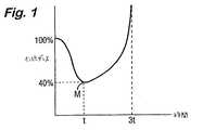
図面を参照すると、図1は、二極式のr. f. エネルギの印加中の時間に対する組織インピーダンスの理想的な挙動を示すグラフである。インピーダンスは、印加の初期段階中、処置されている組織近傍の電解質の加熱の結果、低下していることが見られる。最小値Mが到達され、それに続き、組織が乾燥され導電しにくくなるにつれてインピーダンスは上昇し始める。組織の凝固という点での処置は、最小インピーダンスの点Mのあたりで最適に起こる。この点Mを上回るエネルギの持続した伝達は単に、側方マージンを増加させ、蒸気発生の増加により通常1対の鉗子あご部である印加電極の温度を上昇させ、組織付着の危険を高める役割を果たす。イオン移動度の増加は、37℃〜100℃の典型的な温度変化にわたって60%のインピーダンス低下をもたらし得る。しかし実際には、組織は決して均一な温度ではないため、60%の低下は決して見られない。
【0033】
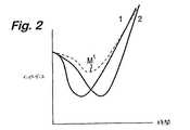
図2は、典型的な二極式の鉗子の接触区域間の異なる点で組織インピーダンスがいかに変化するかを表わす2つの実線の関係を示すグラフである。プロット1は、鉗子あご部がそれらの長さに沿った1つの点でともにより接近しているために起こるかもしれないような、鉗子間のインピーダンスが電力の印加に際し急速に低下する点を示している。その結果、接触区域のこの点は、共通の二極式のr. f. 電源から少しばかり多めの電力を取る。これは次に、インピーダンスのさらなる低下を伴うこの点での加熱と、プロット2に示される点などの他のインピーダンスがより高い接触点を犠牲にした、この点で伝達される電力の結果的な増加とをもたらす。これは電流占有として公知の現象であり、それは導電性組織流体など抵抗の負の温度係数(NTCR)を呈する材料の特徴である。これらの個々の特徴は、当然ながら、点線によって示されるような2つの組合された効果しか見えない共通のエネルギ源によっては見られない。
【0034】
組合された効果の第1の注目すべき特徴は、インピーダンス最小値M1がそれほど顕著ではないということである。第2の注目すべき特徴は、乾燥が起こると、印加された電力に伴うインピーダンスの正の増加が電流占有の反対をもたらすことであり、これは電流共有として公知である。この電流共有は、乾燥が起こり始めると、2つのプロットの収束をもたらす。このため、一旦組織が、付随的な不必要な効果のマージン、組織の硬化、および電極/組織付着を伴って乾燥点に達したときのみ、処置の終点判定が組織茎全体にわたって確実に検出可能である。
【0035】
電流占有現象は、同じ電源が適用される組織の2つの非常に小さな片、つまり同じ電源に平行に接続され、これら2つの微細な組織片に適用される2対の電極を考慮することによって、より簡単に理解され得る。これらの組織片の一方が他方より少しばかり低いインピーダンスを有する場合、それは少しばかり多めの電力を取る。しかし、インピーダンスが低い方の片でのこの少しばかりの電力増加は、より大きな加熱をもたらす。より大きな加熱は、上に説明したように、より低いインピーダンスをもたらす。このため、2つの片の間の電力差は増加し、さらにより大きな電力差をもたらす。これが電流占有現象であり、それは、この例では組織内の電解質を構成するインピーダンスの負の温度係数を有する材料において、常に起こる。組織に適用される実際の電極は、これら2つの両極端間で挙動する無数の組織部分を有効に有する。既に述べたように、これらの部分の各々の電気特性は、乾燥時に収束する傾向を有する。したがって、最も安全なアプローチは、乾燥点を印加電力の終点として用いることであり、これは、発生器の出力での急速に増加する電圧のため、または標的部位での活動の欠如によって、簡単に検出可能である。しかし、これは前に述べた4つの問題を引起こす。したがって外科医は、組織付着および増加する側方熱マージンの危険に対して、処置が血管を封鎖するのに十分であることを確実にしようとするジレンマに直面している。
【0036】
既に述べたように、鉗子表面の上の変動は、初期インピーダンス、温度、電気伝導率、組織厚さ、および電極表面積に起因する。このような変数の多くは大いに相互作用し、したがって切り離すことが難しい。しかしながら、純効果は、鉗子の把持内に含まれる組織全体にわたる電流占有および差エネルギ吸収のうちの1つである。これは、上述の米国特許第5,445,638号に記載されているもののような鉗子を用いる場合に、かなり明らかに示される。凝固の領域は、鉗子の一端で始まり、それに沿って進むのが見られる。これは一般に、凝固が最低インピーダンスの領域(またはあご部の最近傍)で始まり、それが次に電流占有現象を呈するように、あご部が閉じられる際に平行ではないことによって起こる。したがって、凝固が始まった点で付着が起こることなく、あご部の全長に沿った存続可能な凝固の可能性は減少する。
【0037】
実際の試みは、処置される組織が厚いほど、電流占有の傾向は少なくなることを示している。電流占有は独占的な電流経路のために発生する。図3に示すような、郵便切手のような組織の微視的に薄い層1と、「切手」の糊の付いた面に適用されている電極2(概略的にのみ図示する)との極端な一例を考慮されたい。電流がr. f. 源3から1つの角での単一の点4を通って他方の面に通されると、電流は優先的に「切手」を直接わたって他方の面上の電極2へ横断する。より重要なことには、他の領域では電流は「切手」を横断しない。このため、組織内には独占的な電流経路4が設定される。したがって、薄い組織の部分は電流占有の傾向を劇的に増加させる。
【0038】
局所的な温度増加の防止は、電流占有の効果を減少させ得る。前に説明したように、電流占有はより大きな熱を作り出すインピーダンスの減少という周期性の因果関係によって起こり、インピーダンスの減少を引起こす。接触表面にわたって熱を広げることは、この周期性の事象を減少させる。低いインピーダンス点によって提供された熱は、広がった場合、隣接する点のインピーダンスを減少させ、したがって、電流占有の可能性を下げる。先行技術において教示されているように、非常に熱伝導性のある電極表面を用いることは、これを行なうことができる。
【0039】
さらにより魅力的なのは、組織/鉗子接触面の熱を除去してホットスポットの形成を防止することであり、そのため、組織/鉗子境界での組織はより低い温度に保たれ、組織流体は沸騰しないようになる。この措置は、最大温度上昇が表面でというよりはむしろ組織茎内で起こることを確実にし、結果として乾燥は組織内に制限される。先行技術によって同様に教示されているように、十分に大量の熱容量を有する鉗子あご部を提供することは、これを達成できる。
【0040】
組織付着の根本的な原因は、電極または鉗子あご部内での熱の蓄積である。電極が80℃を上回る温度に達した場合、付着は必ず起こり、組織が乾燥に近づいている場合には悪化する。凝固後の電力伝達は、電極を急速に加熱する蒸気を発生させる。電極は乾燥に達するのに、純凝固点(図1に最小値Mとして示す)に達する場合の3倍を上回るエネルギ放散にさらされる。したがって電極は、組織が乾燥状態まで処置される場合、付着温度にはるかに達しやすい。
【0041】
電極と組織との境界面は、標的組織へのエネルギ伝達機構である。一定の接触区域を仮定すると、電極と組織との接触が多少なりとも電気的に抵抗がある場合、および処置された組織からの熱伝導の結果、電極は加熱される。
【0042】
ステンレススチールまたは金の電極を用いる試験では、組織接触インピーダンスは、ステンレススチールよりも金の方が約30%低い。この差は、スチール電極表面上の酸化物層の存在によるものとされる。その重要性および潜在的な利点は未知である。しかしながら、この低下は、この点での電力放散を対応して30%減少させる。これも先行技術によって、特に米国特許第5,885,281号に教示されている。
【0043】
明らかに、電極表面の隣りの組織は熱くなる。組織から処置電極への熱伝導は温度差および時間に依存する。ここで重大な要因は、処置された組織の全体積が電極と熱接触している場合には、印加されたエネルギのはるかにより大部分が電極の加熱に用いられるということである。
【0044】
処置組織の厚さが減少するにつれ、熱伝導経路がより短くなるため、印加されたエネルギのより多くの部分が電極加熱を引起こす。しかしながら、さらにより薄い組織が、より少ない体積のため、より少ない電力しか必要としなくなるにつれて、2つの効果は互いに打消し合う傾向にあり、そのため、組織厚さの結果としての電極温度は比較的一定である。しかしこれは、組織加熱は組織全体にわたって均一に行なわれるという仮説を立てる。実際には、組織のこの薄い層は、電極または鉗子あご部間のインピーダンスのより大きな変動のため、電流占有の発生およびホットスポットの形成に特に影響されやすい。この問題は次に、電極の大量の温度上昇というよりもむしろ、局所的な温度上昇の1つとなる。
【0045】
内視鏡用途用に設計された典型的な二極式の機器は決まって、アクセスポートの限界のため、設計が制限される。5、7.5、および10mmの標準入力ポートサイズがある。そのような機器を設計する機械的局面は常に、鉗子あご部までの長さが長いヒンジ式の設計をもたらす。そのような設計は、小さい機械的な動きで最大の組織係合を可能にする。制限されたアクセスの結果、および先行技術の教示に反して、所与の熱質量またはサイズにとって最大の処置区域を有する鉗子を構成することが望ましい。
【0046】
二極式の内視鏡機器に採用される最も一般的な設計原理の1つは、クレピンガー(Kleppinger)鉗子に基づいている。この種の鉗子を開くことは、機械的なヒンジを用いるというよりはむしろ、鉗子あご部上に作用するばね力によって完全に達成される。閉じることは、あご部の近位ばね部へ外側管状構造を摺動させることによって行なわれる。鉗子あご部は、それらを操作するのに必要な力を制限するため、必然的にかなり薄い。その結果、あご部は所与の接触面にとってごくわずかな熱降下しか提供しない。そのような組織接触部品の機械的および生体適合性特性もステンレススチールなどの材料の使用を招く傾向にあり、二極式のr. f. エネルギの伝達中に生じる熱を降下させるあご部の能力をさらに低下させる。あご部および近位ばね区域はr. f. 電力を搬送し、近位部は通常、熱降下能力をさらに低下させるプラスチックコーティングを用いて絶縁される。
【0047】
クレピンガー動作原理に基づく別の例示的な鉗子設計が米国特許明細書第5,445,638号(ライデル(Rydell)他)に記載されており、この特許に基づいた商品が、米国ミネアポリス(Minneapolis)のエベレストメディカル社(Everest Medical Corp.)によって、BiCOAG切断鉗子として販売されている。この鉗子設計は、組織茎が一旦凝固されると、第2の機器の必要なくそれが分割されるように、鉗子あご部の長手方向軸のまわりに設けられた空間に沿って進められ得るブレードというさらなる特徴を含んでいる。ブレードの動作についての空間要件は、鉗子あご部の熱質量および熱降下能力をさらに一層低下させる。鉗子あご部の対向面は一般に、特にブレードが進む間、機器に把持されている組織がすべらないようにする歯を有する。電気外科機能および把持機能を同時に提供するこれらの歯については、それらは2つの歯車間でと同様に噛み合わなければならない。この構成は、歯が組織を貫通してr. f. 伝達を短絡させることを防止している。残念ながら、歯は、鉗子あご部の表面の処置区域を増加させ、組織からあご部への熱伝達を増加させる効果を有する。歯が鋭利である場合、最良の把持機能が達成され、それは、歯の地点で電流密度を増加させるため、先行技術では反対して教示している特徴である。
【0048】
我々は、二極式のr. f. エネルギの高電力パルスを用いて組織のNTCR挙動をPTCR挙動に変換することにより、鉗子または他の二極式の電極設計におけるこれらの制限を克服しようとしている。電流占有現象を極度に利用することによって、自然のPTCR効果が実現化される。
【0049】
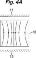
図4A〜4Dを参照すると、二極式の機器の2つの接触面(電極)11および12の間に含まれる組織10に、高電力がたとえば100kHz〜500kHzの範囲の周波数で伝達される場合、図4Aおよび4Bに示されるように、電流占有が結果として起こる。このため、図4Aは、組織内の低抵抗領域が不均一な電流密度をもたらしている、電極11および12への初期電力伝達を示しており、図4Bは、電流占有に起因する電流密度の増加を示している。電力が十分に高い場合には、図4Cに示すように、局所温度のために気泡13が組織内に形成される。この気泡13は、実質的に300V未満のピークの電圧で完全に絶縁する純粋な蒸気を含む。したがって、電流占有現象によって作り出される組織の領域にわたる高電流密度は、気体の絶縁障壁によって打ち負かされる。図4Dに示すように、気泡13の成長は、気泡の周辺に生じ、電流の流れに垂直な線に沿っている領域14での高電流密度の領域によって持続されている。実際、高電流密度の領域は、気体伝搬により外側に押しやられている。気泡13のこの成長が持続可能であった場合、それは爆発性破壊につながり、適用部位近傍外側の組織を損傷し得るであろう。実際その場合、二極式のr. f. 機器/発生器の組合せを用いて印加可能な電力を制限する主な要因の1つは、蒸気泡の破裂であり、それは封鎖を妨げ得るため望ましくない効果である。
【0050】
高電力を断続的にのみ伝達することにより、十分な時間が起動間に許容され、気泡を凝結させ、それにより、電解質の沸騰による圧力蓄積を緩和する。断続的な電力伝達の別の利点は、臨床効果が減速され、電気外科用電力の印加を最適レベルまで検出し制御する上での困難を改善することである。(これらの理由のため、先行技術での電力伝達は通常、約5〜10秒の印加時間と調和するレートに制限されており、その結果、電力の延長された印加は、処置部位近傍での熱損傷をもたらす。)
この手法の一利点は、(唯一の電流占有点による)著しい電流を引く程度までの電流占有が回避されるということである。好ましいシステムは単一のバースト内で多数のホットスポットを生成し、二極式のr. f. エネルギが高電流のものであることを必要とし、それは通常、5mmの腹腔鏡検査用BiCOAG切断鉗子については1.5Aを超え、10mmバージョンについては4Aまでであることがわかっている。
【0051】
高電力バーストの別の利点は、加熱された組織から鉗子11、12への熱伝導が制限されていることである。気泡13が形成されると、組織内には鉗子/組織境界面でよりも高い電力密度が存在する。このより高い電力密度は、多数の気泡によってもたらされるより長引いた電流経路の結果である。したがって、組織下位表面から鉗子あご部は、より高い有効抵抗率を有する。より少ない電流でより高い電圧によってより多くの電力が下位表面組織に伝達され、そのため電極11、12に隣接する組織はそれほど加熱を受けない。実験中、このように処置された組織茎は内部に乾燥の証拠を示すが、表面上には示さない。この発見は、最高電流密度が通常、鉗子あご部と接触する組織表面で起こるような従来の二極式のr. f. 電気外科用電力伝達とは非常に異なる。
【0052】
エネルギ伝達のデューティサイクルは、最良の臨床効果を達成するよう調節可能である。エネルギがこのように組織に伝達される場合、バーストは、組織内の多数の部位に気体形成を引起こすのに十分大きい。実際の実験では、この証拠として、組織は各バーストで膨張することが見られる。次に電力伝達は、気体が組織をバーストさせるのに十分に高い圧力を呈する前に止まる。次の「オフ」期間は、熱緩和を確実にするため十分に長くなければならない。この緩和期間中、気体は再凝結し、最冷却点で優先的に凝結することによって熱伝導機構を支援する。このため、組織内の湿気がこの機構により再分布される。「オフ」時間、結果として生じる熱緩和、および湿気の再分布により、新しい電流占有点が連続する各バーストで作り出されるようになり、電極11、12間に含まれる組織における効果の均一な分布を確実にする。
【0053】
電力伝達に関連する困難のうちの1つは、使用中に遭遇されるインピーダンスの範囲である。典型的なインピーダンスは10オーム〜200オーム間のいずれかにあり得る。最大印加電圧は、気体内のアーク伝搬を防止する予め定められたピークレベルに制限されている。したがって、ピーク電圧は、たとえば電圧クランプ回路を用いて200V未満に維持されている。この上限電圧での最大電力伝達のため、波形は、通常1.5未満の低い波高因子のものである必要がある。最も実用的な低波高因子の波形は、波高因子が1.4の正弦波である。したがって、最大実効値電圧は、実効値で140Vである。最大初期電力伝達は、したがって、100W〜2000Wの範囲であり得る。
【0054】
しかしながら、機器設計は最大電力伝達を制限し得る。抵抗損失の結果としての機器の加熱はできるだけ避けるべきである。一般に、所与の区域の鉗子あご部間に把持された組織が薄いほど、インピーダンスは低くなる。このため、r. f. 源が一定の電圧源として挙動した場合、電力伝達は組織の厚さに反比例するであろう。しかしながら、より薄い組織は、凝固するのに厚いものよりも少ないエネルギしか必要としない。たとえば、組織の厚さが半分である場合、半分のエネルギが必要とされるが、電力伝達は2倍になる。一定のr. f. 電圧供給では、したがって、デューティサイクルを変えて臨床効果の速度の変動を減少させることが望ましく、効果の速度は厚さの2乗に比例する。特定の機器を、組織の厚さの5:1の範囲にわたって用いることが可能である。効果変動の速度は25:1であろう。したがって、一定電圧および可変デューティサイクルの方策は、好ましくない。前に概説した理由のため、薄い組織において電流占有を克服する必要性は、厚い組織においてよりも大きい。機器が最大で組織が最も薄い場合に下位表面気体を達成するのに、200Wのピーク電力が非常に十分であるということがわかっている。機器互換性の点で、バースト持続期間というよりもむしろ電力要件を制限することが有利であり、処置時間の変動を減少させ、r. f. 発生器に対しそれほど要求しない。一定のr. f. 電圧を維持しつつバースト持続期間を変更することは、異なる厚さに対し異なる処置レートを産出する。
【0055】
付着を誘発する最悪の場合は、電流共有の欠如のために組織が薄い場合であり、これはしばしば、機器設計の要件によって複雑にされる。単一のr. f. バーストに関する限り、多数の気体ポケットを生成するために十分なエネルギが供給される。バーストのエネルギ要件は、把持された組織の体積によって、したがって鉗子あご部の寸法によって決まる。幅広い範囲の機器構成にわたり、100℃に達するためのエネルギ要件は、2〜20Jの範囲に位置していてもよい。したがって、200Wでの最小バースト幅はそれぞれ10ms〜100ms間である。気化の潜熱は、20〜200Jの対応するエネルギ要件を規定する。これは、バーストが100msの間200Wに設定されている場合、把持された最小組織体積の全電解質を気化するのに十分なエネルギがあることを示唆している。実際、気体の下位表面生成はインピーダンスの劇的な増加を引起こす。気体形成および上述の電圧クランピングは自動調整効果を作り出し、そのため、ホットスポットを引起こすのに必要なものを上回るエネルギ伝達が制限される。完全な気化に必要なエネルギは10倍大きいため、利用可能な設定の大きな動作ウインドウがある。したがって、1バーストあたり潜在的な20Jのエネルギで動作することが可能である。しかしながら、組織が厚い場合には、この最初のバーストが気体を生成する必要はない。より厚い組織内での気体の生成は、破裂のより高い潜在的な危険を有する。最大電圧クランプの自動調整は、より厚い組織によって生成されるより高いインピーダンス内にバーストエネルギを減少させる。したがって、前の分析において示されたものよりも低いバーストエネルギが使用可能であり、さらに組織効果を達成する。自動調整効果は電力伝達の関数である。所与のエネルギについてバースト電力が低いほど、この効果は顕著ではなくなる。
【0056】
次の「オフ」時間は、凝結および熱緩和を可能にする。これは比較的遅いプロセスである。熱い気体は比較的迅速に凝結するが、その次の熱伝導は遅い。熱質量および熱伝導率が低い鉗子を用いて、十分な熱緩和が起こり得る前に100msを上回る期間が必要とされることがわかっている。300ms〜1sの範囲の値が好ましい。この熱緩和は、次のr. f. バーストが組織の前に処置されなかった区域にホットスポットを生成することを確実にするのに重要である。各バーストの「オン」時間は通常、約100〜500msである。これらの数値は、この明細書で言及されるマーク対スペース比およびデューティサイクル値と同様に、電力、電圧または電流波形に当てはまる。
【0057】
バースト時間と緩和時間とのサイクルは、鉗子の把持内に含まれる組織が完全に処置されるまで持続される。より厚い組織のより高い熱容量のため、気体が最初のバーストでは発生せず、続いて起こるバーストでしか発生しない場合がある。気体発生の電気的な証拠は、各電力バースト中にモニタされる電流および電圧軌跡に提供される。気体が生成される場合、電圧クランプが到達され、電流は減衰する。次のバーストは、「オフ」時間中の凝結の結果、より高い初期電流を生成する。この初期電流は、前のバーストの末端電流よりも通常50%大きい。気体生成の自動調整効果は、電圧クランピングとともに、完全な乾燥を防止する。各バースト中の電流は、各バーストについての平均値が同様の態様で減少している指数関数的減衰に類似した減衰を呈する。平均伝達電流がそのピーク値の約30%またはそれ未満まで減衰した場合、血管封鎖が起こる。完了点について最も注目すべき特徴は、電極11、12に接触する処置された組織の外部表面が依然として湿っている、ということである。この湿気が気化されていないということは、さもなくば表面蒸気が隣接する組織上で凝結する結果起こるであろう、処置部位を超えた熱損傷の広がりを防止するのを助ける。湿気は組織付着も防止し、処置の均一性により、従来のシステムに固有の表面乾燥の必要なく、凝固終点のより確実な判定が可能になる。
【0058】
図5〜11は、従来のように、およびこの発明に従ったシステムの一部として操作されたBiCOAG切断鉗子Fの使用を示す。これらの図の各々は、鉗子Fをその遠端からおよび側方からそれぞれ見た2つの斜視図を示す。このため、図5は、鉗子Fのあご部21、22に把持された組織茎Pを示し、鉗子は従来の態様で操作されている。鉗子あご部(電極)21、22間の電流密度は組織接触区域にわたって可変であり、図5の矢じり記号23によって示される高電流密度の帯域を生成する。とりわけ、鉗子Fが非平行に閉じることの結果起こり得るインピーダンスの変動が、高電流密度の帯域23を生成する。高電流密度の帯域23は、組織と鉗子あご部21、22との間の接触面にホットスポットを生成する。高電流密度の帯域23に生成されたホットスポットは、組織の他の区域に比べ、これらの帯域のインピーダンスをより一層減少させる。出力からの電流はすべてこれらのホットスポットに集中するようになり、それは電流占有の現象を呈する。表面上の組織が完全に乾燥し、インピーダンスが降下するまで、ホットスポットはさらにより熱くなる。そのときのみ、未処置の組織の区域がそれから処置される。このことは、印加中に効果があご部の長さに沿って動くことが見られるので、鉗子あご部の近端が先端よりもより接近して対向している場合に十分実証される。電流占有は2つの望ましくない効果をもたらす。1つは、完全な処置を確実にするために組織表面を乾燥させなければならないということであり、それは組織付着の危険を高め、もう1つは、完全な処置を確実にするために印加時間を延長しなければならないということであり、それは付帯マージンを増加させる。
【0059】
この明細書に記載された発生器およびシステムは、以下の方法でこれらの問題を克服する。高電流密度の帯域は、図1に示すように、二極式のr. f. エネルギのバーストによって瞬時に生成される。既に記載したように、より高い電流密度のこれらの帯域は、鉗子あご部がともにより接近している場合、より薄い組織においてより生成されやすい。この状態は、まず組織をあご部内に把持し、好ましくはBiCOAG切断鉗子上に歯止め機能を採用して組織が最適の断面に押し潰され保持されるようにすることによって、作り出すことができる。これらの状況の下で第1のパルスが印加されると、高電流密度の帯域の組織はほぼ瞬時に100℃に達する。
【0060】
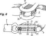
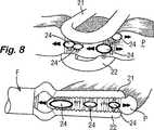
図6〜11は、この発明に従ったシステムの一部として操作される場合の鉗子Fの使用を示し、つまり、鉗子Fはこの明細書に記載されるようにr. f. 発生器によって電気外科用エネルギを供給される。このため、図6に示すように、第1のパルスの電力は、高電流密度の帯域23において組織茎Pの中央に放散され、細胞内液および間質液内に水蒸気(蒸気)のポケット24を生成する。気体ポケット24を形成するため、高電流および高電力が用いられる。そのような電力および電流レベルは、「乾燥域」電気外科用の従来の二極式の電気外科用発生器からは一般に利用できない。気体ポケット24の生成は2つの利点をもたらす。1つは、気体ポケット24がさらなる電流占有を防止する高インピーダンス障壁を生成することであり、もう1つは、図7に示すように、気体ポケットの側縁のまわりに最高電流密度が起こることである。熱発生および凝固は、組織と鉗子あご部21、22との間の外部接触区域においてというよりもむしろ、組織茎P内で内部から始まる。
【0061】
図8を参照すると、電流の流れ用の最小抵抗の経路が、気体ポケット24のまわりにある。この電流の集中は、気体ポケット24を、最高温度が起こるそれらの側縁で膨張させる。したがって、組織効果は茎P内の未処置区域に自然に移行する。使用中、組織が各エネルギパルスで膨張することが見られる。しかしながら、気体が成長し続ける場合、電流を伝導する組織はだんだん少なくなるであろう。これは気体をはるかにより急速に発生させ、そのため、潜在的な暴走状態が起こる場合があり、従来の発生器からの延長された印加に関連するバーストまたは破裂をもたらす。この発明のシステムの自動調整機能は、過度の気体形成が起こった場合に、所与のエネルギパルスの電力をマイクロ秒単位で遮断する。過度の気体形成は、上述のバースト時間および緩和時間のサイクルに従ったエネルギパルスの終了によってさらに回避される。
【0062】
図9を参照すると、第1のエネルギパルスが終了すると、気体ポケット24は崩壊し、組織茎P内部に乾燥の区域25を残すが、鉗子あご部21、22と茎との間の表面上には残さず、その表面は湿ったままである。
【0063】
気体が凝結するにつれ、組織茎P内に生じた熱は、茎のより冷たい区域で放散する。この熱緩和が一旦起こるようになると、図10に示すように第2のエネルギパルスが印加される。第1のエネルギパルスによって生成された乾燥した組織のより高いインピーダンスのため、高電流密度の帯域23が今回、前に処置されていない区域に生成される。気体ポケット24(図10には図示せず)が再度これらの帯域に形成され、側方に広がって任意の未処置区域を含む。
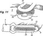
【0064】
各パルスでの電力吸収が、図11の参照符号26によって示されるような完全な乾燥を示すレベル未満に降下するまで、二極式のr. f. エネルギパルスのオン−オフサイクルは持続される。この点は、高電流密度の帯域がそれ以上生成できない点に対応する。これは、茎P内の組織が表面凝固を伴って均一に処置されているものの乾燥してはいない場合に自動的な表示を与える。組織茎P内に、あご部21、22に隣接するその表面が湿ってあご部に付着しないままである状態で、最大の効果がもたらされる。
【0065】
上述の措置は、血管茎のより急速で均一な凝固を、骸骨化の必要なく提供する。骸骨化は、血管を通常取囲む脂肪および結合組織を除去して血管自体を露出させる外科的手法である。これは、茎内のより低いインピーダンスの血管構造への二極式のr. f. エネルギの伝達にとって実際に高インピーダンス障壁であるものを除去する。この状況におけるこの発明のシステムの利点は、茎内でのエネルギの優先的な吸収によって提供される。
【0066】
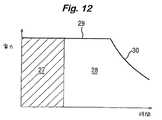
システムの実際の使用中、外科医は、治療効果を達成するのに、従来の持続的な二極式のr. f. 出力を用いた場合よりも少ないエネルギしか伝達する必要がない。図12のグラフは、持続的な出力の二極式のr. f. 源から伝達された、或る量の時間にわたる或る量のエネルギの伝達の後の、組織における治療効果を示す。処置サイクルの初期段階27の間、エネルギ伝達は有効である。電流占有が起こるにつれ、いくつかの組織区域は他のものより前に治療レベルに達する。止血するためには、すべての組織区域がこのレベルに達する必要がある。これらの他の領域が治療温度となることを確実にするため、電力をより長い時間印加しなければならない。処置サイクルのこの延長期間28の間、印加されたエネルギの大半は、始めに電流占有点を形成した領域の電解質を沸騰させることに浪費される。適切な処置時間はしばしば決まっていないため、完全な乾燥が起こるまで電力が印加される。電力が予め設定されたレベル29に維持されている間、沸騰が起こる。乾燥が一旦起こると、負荷インピーダンスは増加し、図12の曲線の減衰部分30によって示されるように、伝達された電力は減少する。電解質のこの過度の沸騰は、組織付着、炭化および側方熱マージンの説明に役立つ。
【0067】
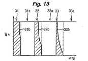
図13のグラフは、3つのr. f. パルス31、32および33が印加された後に、いかにして所望の治療効果がこの発明のシステムを用いて到達可能であるかを示す。各パルス31、32、33にはそれぞれ「緩和期間」31a、32a、33aが続く。印加された第1のパルス31は、気体を生成可能である。この気体は内部に形成されるため、それは電力伝達を妨げ、パルスの終りに向かって電力の減少(線31bによって示す)を引起こす。次に、関与する少量の電解質を気化することによって吸収されるエネルギが「緩和期間」31a中に再分布され、その後、エネルギの次のパルス32が伝達される。この再分布は凝結によって起こる。次の各パルスによって生成される気体の量はより多く、そのためより一層の電力減少だけでなく、組織全体にわたるエネルギのさらにより大きな分散ももたらす。凝結する気体によるエネルギのこの再分布は、各パルス用の初期エネルギ伝達が気体によって妨げられないということによって実証される。図13の影によって表わされるように、各パルスのエネルギはほぼ全部有効である。過度のエネルギがほとんどまたは全く用いられないため、また、加熱が内側から外側へ起こる(外科医がたとえば熱処置マージンが必要とされる場合などに他のやり方を選択しない限り)ため、付着、炭化または付帯組織損傷を引起こす過度の熱エネルギはほとんどない。図12および13のグラフは、1対の鉗子を病的な血管組織に適用し、持続的にまたはパルス状にそれぞれ通電することによって、得ることができる。
【0068】
図14を参照すると、この発明に従った電気外科用システムは、無線周波数電力を発生させるための発生器40と、手持ち鉗子ユニット42のアセンブリ、接続ケーブル44、および、発生器出力端子を含む発生器コネクタ48を介してアセンブリを発生器40へ取外し可能に接続するためのコネクタ46を含む電気外科用機器とを含む。鉗子ユニット42と発生器40間の接続インターフェイスは、発生器上にある代わりに、鉗子ユニット42自体上にあってもよく、重要な点は、代替的な処置ユニットが、鉗子であれその他のものであれ、発生器40に接続され得ることである。
【0069】
鉗子ユニット42は、鉗子ユニット42の本体およびケーブル44を通る電力伝達導体52を介してコネクタ46に結合されている1対の電極50を有し、それらはコネクタ46で発生器コネクタ48内の発生器の出力端子(詳細には図示せず)の2つに接続され、発生器から電極への無線周波数電力の供給が可能になる。電極50への供給用の無線周波数電力は、発生器コネクタ48内のそれぞれの出力端子に関連する出力ライン62を有するr. f. 出力ステージ60において発生される。上述のように、発生器40は、100kHz〜500kHzの範囲の搬送周波数で、および通常約0.7〜3Hzのパルス繰返し数で100%の振幅変調無線周波数電力を供給するよう構成されている。変調波形は、パルス変調器64により結線66を介してr. f. 出力ステージ60へ送られる。
【0070】
出力ステージ出力ライン62間で発生されるピークr. f. 電圧は、ライン62間に結合された電圧しきい値検出器68とコントローラステージ70との組合せによって、通常200Vのピークに制限されている。コントローラによってしきい値設定ライン72を介して設定された電圧しきい値が、設定されたしきい値電圧を上回るピーク出力電圧を検出すると、しきい値検出信号が検出器出力ライン73を介してコントローラ70へ送られ、コントローラ信号が電力設定ライン76を介して印加されて、出力ステージ60へ電力を供給する切換モード電源74を調節することによって、r. f. 電力が減少される。
【0071】
コントローラ70の別の機能は、パルス変調器64によってr. f. 出力ステージ60に印加されるパルス変調の周波数およびマーク対スペース比を設定することである。
【0072】
コントローラ70はまた、変流器78によって出力ライン62の1つに結合された電流検出器回路77から、出力電流検出信号を受ける。
【0073】
システムの使用中、外科医がたとえば鉗子ユニット42の電極50間で茎を凝固させることを所望する場合、外科医は鉗子を操作して電極50間の茎を把持し、足踏みスイッチ(図示せず)によって発生器40を起動させ、その結果r. f. 出力ステージ60がパルス変調器64によって起動され、そのため100%振幅変調r. f. 信号が、コントローラ70により設定された周波数で電極50に送られ、マーク対スペース比は、出力ステージ60の「オフ」時間が、コントローラ70およびパルス変調器64により決められるように、連続する各パルス間で少なくとも10msであるようになっている、ということが理解されるであろう。連続するパルスで、印加電力は図13に示されたパターンに従い、気体が組織内に形成されるにつれて、瞬間電力は各パルスの終りに向かって減衰する。上述のように、「オフ」時間31a、32a、33aは各々、次のパルスの印加前に組織内の気体を凝結させるのに十分であるが、連続する各パルスでは、電力は、前のパルスで起きたものよりも低い終了値に減衰している。この発明の実施例では、この減衰は電流検出器回路77およびコントローラ70によって感知され、コントローラは、パルスのうちの1つの終りでの実効値電流がそのパルスの始めでの実効値電流の予め定められた一部未満に低下している場合に、パルスを終了させるよう構成されている。この場合、終了電流が開始電流の30%またはそれ未満である場合に、パルスは遮断される。したがって、この実施例では、電流しきい値を用いてパルスのシーケンスを終了させる。つまり、r. f. 電流が予め定められた電流しきい値未満に低下した場合に終了が起こる。一代替例として、発生器40の感知回路は、電力に比例する感知信号をコントローラへ伝達するよう構成されていてもよく、そのため、瞬間電力が予め定められた電力しきい値未満に低下した場合に、処置は終了され得る。この原理についての変動が用いられてもよく、絶対的な電流または電力しきい値、または、処置の開始時の値の一部として、もしくは問題のパルスの開始時の値の一部として特定される電流または電力しきい値を含む。
【0074】
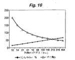
この点で、パルス状出力と電圧制限(通常、実効値で120V)との組合せが、持続的な出力で動作する従来の発生器のものよりも幾分狭い電力対インピーダンス負荷曲線(パルス全体にわたって平均化される)を作り出すことは、言及に値する。これは図15に示されている。この発明の発生器は通常、15%のデューティサイクルで200Wの瞬間電力出力を生成でき、電流は実効値で約1アンペア〜5アンペアの値に制限されており、それは10オーム〜100オームの負荷インピーダンス間で電力ピークを産出する。これに対し、通常30ワットの平均電力で動作する従来の発生器は、たとえば10オームから100オームを十分上回るまでの10倍の範囲のインピーダンスにわたって、電力が最大値またはその近傍に維持されている、ほぼ平坦な電力対負荷インピーダンス曲線を作り出す。図15では、点線の曲線Aは、ピーク電力出力が200W、電流定格が実効値で4アンペアの15%デューティサイクルパルス状出力に対応している。実線の曲線Bは、30Wの持続的なr.f.出力で動作する従来の発生器についての電力対インピーダンス特性を表わしている。双方の曲線は、実効値で120Vで電圧制限されている。パルス発生器はその最大電力を、持続的に動作する発生器よりも狭いインピーダンス範囲にわたって伝達するが、にもかかわらず最大電力はわずか20オームで始まる負荷インピーダンス範囲にわたって伝達される、ということが見られるであろう。負荷を20オームに下げた場合、ピーク電力伝達についての現実的な下限は100Wであり、このピーク電力が伝達され得る最大インピーダンスが、アーク放電を防止するために課される電圧制限(ここでは実効値で120V)によって決まることを認識する。負荷曲線の幅における制限は、それが処置の終わりに上述の自動調整機能を提供する限りは、望ましい。電力が低負荷インピーダンスに伝達され得る程度は、発生器の電流定格によって支配される。この発明の発生器では、各パルスの開始時に1.5アンペアを超す実効電流値が通常達成され、3または4アンペアが到達可能である。
【0075】
鉗子ユニット42の電極50がそれらの組織接触区域において比較的大きい場合、発生器に提示される負荷インピーダンスは比較的低い、ということが理解されるであろう。負荷インピーダンスはまた、電極50間に把持された組織の厚さが減少するにつれても減少する。発生器によって生成されたパルスを、それが接続される機器の特性に従って変更することにより、処置の速度を高めることが可能である。広い区域の電極は低負荷インピーダンスを生成するが、把持された組織のより広い区域の熱緩和時間は、より長い熱伝導経路のため、より長い。より小さい区域の電極は、より短い熱緩和時間によるより大きなデューティサイクルまたはマーク対スペース比で、およびより低いピーク電力で扱われ得る。より大きなデューティサイクルは、(より高いインピーダンス値へ延びる電力対負荷ピークのため)高インピーダンス負荷に整合する発生器の能力を高める効果を有する。したがって、電極の区域が小さい場合にデューティサイクルを増加させることは、より迅速な処置という利点を提供する。
【0076】
次に、上部電圧クランプとともにパルスデューティサイクルを変更することは、使用中の機器に適するよう負荷曲線を変更する効果を有する。再度図14を参照すると、パルス特性の調節は、鉗子ユニット42などの発生器40に接続されることになる機器を、機器が発生器出力コネクタ48に接続されている場合に発生器の感知回路82により感知され得る識別素子80を有するように構成することによって、行なわれてもよい。図14に示す例では、識別素子80は、ケーブル内の電力リード線52のうちの1つと第3のリード線84との間に結合された、特定の値のキャパシタである。これらの同じ2つのリード線は、コネクタ46、48を介して、キャパシタの値に応答することにより電極識別回路として作用する感知回路82の1対の入力86に結合される。コントローラ70は、識別回路82からライン88を介して受ける識別信号に従ってパルスデューティサイクルを変える。電極識別回路82、および識別素子80とのその相互作用の詳細は、欧州特許公報0869742Aに記載されており、その内容をここに引用により援用する。
【0077】
したがって、異なる値のキャパシタ80を、たとえば負荷インピーダンスおよび熱緩和時間に影響を与える機器の電極組織接触区域および他の特性に従って、異なる機器に組込まれるよう構成することによって、発生器は、問題の機器に特に好適なパルス状出力を生成するよう自動的に構成可能である。特に、組織接触区域がより大きな機器が選択されるにつれて、予め設定されたデューティサイクルまたはマーク対スペース比は低下され、および/またはパルス周波数は低下される。
【0078】
コントローラは、マーク対スペース比だけでなく、パルス周波数および電力出力を、この場合はパルス変調器64および/または切換モード電源76を介して、変更してもよい。
【0079】
機器または機器範疇を識別する代替例として、発生器40には、外科医が電気外科処置を開始する瞬間またはその前後に出力ステージ60の出力ライン62間の負荷インピーダンスを感知するための感知回路が設けられていてもよく、それにより設定されたパルス特性は、処置が終わるまで維持される。図15を参照すると、図示されているように、パルスデューティサイクルは初期負荷インピーダンスの増加とともに増加され得る。図示された例では、デューティサイクルは約140オーム未満のインピーダンスについて50%(つまり1:1のマーク対スペース比)未満に維持されている。図15および16をともに参照すると、コントローラは、また、初期負荷インピーダンスに従ってピーク電力(図15)とパルス周波数(図16)とを並行して設定するよう構成されていてもよく、高い初期インピーダンスに対してよりも低い初期インピーダンスに対して、電力はより高く設定され、パルス周波数はより低く設定される。公知の初期に印加された電力に対し、初期負荷インピーダンスが出力電流の2乗に反比例すると仮定すると、初期インピーダンスは電流をモニタすることによって感知されてもよい。
【0080】
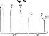
単一の予め設定されたデューティサイクルの複数のパルスからなる処置サイクルを行なうよう発生器を構成するだけでなく、発生器出力信号が予め定められたデューティサイクルを有するパルス状r.f.信号として始まり、異なる特性を有して終了する期間に処置サイクルを分割することによっても、さらなる利点が獲得され得る。図18の電力対時間グラフを参照すると、処置サイクルは、r.f.電力信号が予め定められたデューティサイクルを有する一連のパルス131、132、133からなっている初期期間130を有していてもよく、その後に、r.f.電力信号がはるかにより低い電力振幅のc.w.信号141である次の期間140が直接続く。通常、初期期間130の間、パルス131〜133は、200Wのピーク電力で約15%〜30%のデューティサイクルを有する。初期期間130から次の期間140への遷移は、発生器の出力回路からのフィードバックによって制御されてもよい。再度図14を参照すると、切換モード電源74はコントローラ70によりライン76を介して制御され、コントローラ70は、出力電圧しきい値検出器68からのライン73上の感知信号に応答している。電源74は切換モード装置であるため、それ独自の切換周波数を有しており、それはこの実施例では約25kHzで、コントローラ70からのパルス流として供給されてもよい。この例では、発生器40のr.f.出力電圧は、出力電圧が予め定められたしきい値(上述のように、通常、実効値で120V)を超える場合、電源74に供給される切換パルスを遮断することによって制限される。コントローラ70によって発生される電源切換パルスをモニタすることにより、発生器によって伝達されるエネルギの量を判断することが可能である。したがって、切換パルスを数えることは、発生器出力での電気的条件をモニタする便利な方法を提供する。特に、図18を参照すると、組織内での気体の形成による、電力波形における減衰曲線132bおよび133bとして見える、伝達電力の減少は、出力電圧が電圧しきい値検出器68(図14)において設定されたしきい値を超えたことに応答して生成された電源切換パルスの遮断の結果である。したがって、電源切換パルスを数えることにより、低いデューティサイクルの波形がいつ有利に終わるかを判断することが可能であり、その結果、コントローラ70はその出力を調節して、図18のc.w.波形141によって示されるように、持続的にまたはよりほぼ持続的に、しかし著しくより低いピーク電力レベルで、エネルギを切換モード電源に伝達させることができる。通常、処置サイクルのこの次の期間140の間に伝達される平均電力は、初期期間130中に伝達される平均電力と同じである。
【0081】
よりほぼ持続的な電力伝達は、代わりに、図19に示すように、次の期間中のr.f.電力信号を、デューティサイクルは著しくより高いもののピーク電力はより低いパルス状信号の形をとるよう構成することによって達成されてもよい。この実施例では、コントローラ70は、前と同様、処置サイクルの初期期間130が低いデューティサイクルと高いピーク電力とを有する複数のパルス131、132、133からなるよう構成されている。ここでも、次の期間140への遷移は、発生器出力での電気的条件に応答して実行される。しかし、次の期間140では、デューティサイクルはたとえば初期期間のものの少なくとも2倍高く、ピーク電力は対応して減少し、結果として少なくともほぼ同じ平均電力をもたらす。次の処置サイクル期間140中にさらなる気体形成が組織内で起こる場合があり、パルス143の減衰部分143bから明らかなように、初期期間中と同様の電圧クランプの動作をもたらす。
【0082】
図面には示されていない代替的な一実施例では、処置サイクルは、r.f.電力信号が異なる特性を有する3つ以上の期間を有していてもよい。特に、信号は、第1の低いデューティサイクルを有するパルスの第1の群で始まり、次に第2のより大きなデューティサイクルを有するパルスの第2の群が続き、次に第3のさらに大きなデューティサイクルを有するパルスの第3の群が続くといったパルスの連続からなり、組織の特徴が変わるにつれ最適の凝固効率を維持するようになっていてもよい。言い換えれば、3段階の処置サイクルが採用されてもよく、各段階はそれ独自のそれぞれの一定のデューティサイクルを有する数々のパルスからなる。通常、ほぼ一定の平均電力伝達を維持するため、連続する段階は、15%、30%、および60%のデューティサイクルと、200W、100W、および50Wのピーク電力値とをそれぞれ有するパルスを有する。
【0083】
上述の3つの代替例すべてに共通する効果は、発生器の負荷曲線は、始めは図15の曲線Aによって例示されるような狭い特性を有しているが、エネルギ伝達が、図18のようなc.w.出力141の形であろうと、または図19のようなより高いデューティサイクルを有する出力の形であろうと、よりほぼ持続するようになるにつれて、高いインピーダンス範囲に拡張される、ということである。要するに、気体形成およびその後の組織の局所化された凝固により組織インピーダンスが増加するにつれて、組織への電力伝達が維持されるため、処置されている組織の凝固がより迅速に進む。
【0084】
血液または他の導電性流体に浸された血管を凝固させようとする場合に、この発明の一利点が示される。従来の二極式の発生器では、血液の存在により、電流は、組織または出血している血管にというよりもむしろ血液に放散されるようになる。これは、血液が2つのあご部間の組織よりも良好に電流を伝導するためであり、電流占有を作り出す状態である。すなわち、止血を達成するには、電流を長い時間印加しなければならず、それによりホットスポット、炭化および付着が確実となる。この発明のシステムを用いると、二極式のr.f.エネルギパルスは非常に短時間の間印加され、気体の形成が電流占有を防止する。これは、組織が止血を達成するのに十分なエネルギを受け、ホットスポットの結果血液中に優先的に放散しないことを確実にする。
【0085】
この発明のシステムの特徴は、血管構造が無血の様態での分割または解剖を必要とする内視鏡手術を行なう際に特に有用である。典型的な処置は、子宮および他の関連する血管が分割を必要とする腹腔鏡支援膣式子宮摘出術および腹腔鏡子宮膣上部切断術、短い胃血管および他の関連する血管が分割を必要とする腹腔鏡ニッセン(Nissen)胃底襞形成術、しばしば腸間膜血管が分割を必要とする、腸への腹腔鏡処置、虫垂動脈および他の関連する血管が分割を必要とする腹腔鏡虫垂切除術、網血管が分割を必要とする網の可動化、卵管を凝固させて不妊を引き起こす腹腔鏡二極式卵管結紮、および、一般に血管癒着の分割のための腹腔鏡処置を含む。どの場合も、血管構造の解剖を長引かせてそれらを封鎖および分割前に外骨化することなく、焼灼が達成され得る。
【0086】
他の例示的な内視鏡処置は、血管構造(内胸動脈または胃大網動脈など)がバイパス前の枝の分割により可動化される最小アクセス心臓手術、および、再度支流が分割を必要とする他の血管構造(伏在静脈など)の採取を含む。
【0087】
この発明は、二極式の鉗子での使用に限定されていない。それは凝固を行なう他の二極式の機器において有利になるよう使用されてもよい。二極式の解剖フックなどのそのような機器の2つの極はしばしば、フック間のどの導電性材料もが、機器が適用される組織へのエネルギの浸透が制限された状態で最短の導電経路を作り出すように、近傍にある。気体形成の結果、フック間の電流経路を直接遮断することによって、従来の出力に比べてより大きな効果が組織において得られ得る。
【0088】
二極式の鉗子などの開放性の外科用機器が使用されてもよい。
上述の好ましい実施例では、所望の臨床効果をもたらすためのr.f.電力の印加は、把持された組織内に気体を生成可能な最小バーストエネルギで行なわれる。特に、組織が薄い場合、バーストエネルギは、最初のバーストから気体を生成するのに十分高い。このエネルギは電圧クランピングがバースト内で起こるのに十分高い電力で伝達され、少なくとも100msの次のバーストの前の熱緩和時間が可能となる。
【図面の簡単な説明】
【図1】 二極式のr.f.エネルギの印加中の時間に対する組織インピーダンスの理想的な挙動を示すグラフである。
【図2】 電流占有の現象の結果としての、時間に対する組織インピーダンスの複合挙動を示すグラフである。
【図3】 r.f.源が組織の層状部分間に印加された場合の電流占有に関連する電流分布密度を示す概略的な回路図である。
【図4A】 組織の層状部分内に気泡が形成される場合の電流密度の変動を示す概略的な図である。
【図4B】 組織の層状部分内に気泡が形成される場合の電流密度の変動を示す概略的な図である。
【図4C】 組織の層状部分内に気泡が形成される場合の電流密度の変動を示す概略的な図である。
【図4D】 組織の層状部分内に気泡が形成される場合の電流密度の変動を示す概略的な図である。
【図5】 従来のように操作される鉗子を用いて組織茎上に得られる効果を示す図である。
【図6】 この発明に従ったシステムの一部として操作される鉗子を用いて組織茎上に得られる効果を示す図である。
【図7】 この発明に従ったシステムの一部として操作される鉗子を用いて組織茎上に得られる効果を示す図である。
【図8】 この発明に従ったシステムの一部として操作される鉗子を用いて組織茎上に得られる効果を示す図である。
【図9】 この発明に従ったシステムの一部として操作される鉗子を用いて組織茎上に得られる効果を示す図である。
【図10】 この発明に従ったシステムの一部として操作される鉗子を用いて組織茎上に得られる効果を示す図である。
【図11】 この発明に従ったシステムの一部として操作される鉗子を用いて組織茎上に得られる効果を示す図である。
【図12】 従来のように操作された鉗子を用いたエネルギ伝達の効率を示すグラフである。
【図13】 この発明に従った第1のシステムの一部として操作される鉗子を用いたエネルギ伝達の効率を示すグラフである。
【図14】 電気外科用発生器と1対の鉗子の形をした機器とを含む、この発明に従ったシステムを表わした図である。
【図15】 持続モードおよび15%のパルスデューティサイクルでのパルスモードで動作される場合の、負荷抵抗の関数としての電気外科用発生器の平均出力電力を示すグラフである。
【図16】 この発明に従った発生器の一実施例における初期負荷インピーダンスによるパルスデューティサイクルおよびピーク電力の変動を示すグラフである。
【図17】 同じ発生器における初期負荷インピーダンスによるパルス周波数の変動を示すグラフである。
【図18】 この発明の第2の実施例における伝達された電力の経時変動を示すグラフである。
【図19】 この発明の第3の実施例における伝達された電力の経時変動を示すグラフである。[0001]
The present invention relates to an electrosurgical instrument, an electrosurgical method, and an electrosurgical system. More specifically, the present invention provides a bipolar radio frequency (rf) electrosurgical output, which is characterized by a faster vasculature such as may be performed during endoscopic surgery, Resulting in a more controlled and more effective blockade.
[0002]
The use of rf current to perform body tissue cutting and coagulation has been known for many years and is under extensive explanation of electrosurgery. Two methods of transmitting rf currents to tissues are currently in common use.
The first of these, unipolar electrosurgery, involves active (tissue treatment) electrodes and remote return (or neutral) electrodes (or pads) placed on the external surface of the patient's body. With use. Current flows from the active electrode through the target site and through other tissues present in the path between the target site and the return electrode. This configuration provides the possibility of extra-site burns, in other words, tissue burns that occur at sites other than the target site. The medical literature includes capacitive coupling of rf currents to other devices that cause burns, direct coupling to tissue due to poor insulation, burns along the current path through the patient's body, and burns that occur at the application site of the return pad. Includes references to numerous examples.
[0003]
The second technique is known as bipolar electrosurgery. Bipolar electrosurgery involves confining the current flow locally to the target site by bringing both the active and return electrodes close together and usually incorporated into the tip of the surgical instrument. This configuration avoids the need for current flowing through the body to complete the electrical circuit, thus eliminating the risk of extra-site burns. Therefore, the use of bipolar electrosurgery has limited visualization when safety is a primary concern, especially when rf current is applied near critical structures or during endoscopic surgery. Is preferred. As a result, bipolar coagulation or sealing of blood vessels during endoscopic surgery has become a cost-effective and easy-to-use alternative to mechanical sealing of blood vessels using metal clips, staples or ligatures.
[0004]
In general, an electrosurgical instrument used for bipolar coagulation is composed of a pair of forceps, and each jaw portion of the forceps is an rf electrode. Depending on the size of the forceps and thus the amount of tissue contained in the circuit, the applied power can typically vary between 1W and 50W. The most serious problem encountered when using conventional bipolar rf electrosurgery relates to the distribution of energy across the tissue grasped between the forceps. As a result of these restrictions, the surgeon theoretically has enough to seal the vessel effectively to ensure complete blockage and then reduce the risk of bleeding when the vessel is split. A higher rf energy is usually applied. This leads to excessive spread of coagulation to the adjacent tissue and increases the risk that the jaws of the forceps will adhere to the tissue. This attachment can be severe enough to cause the coagulated tissue to tear upon release of the forceps, leading to damage to the untreated area of the blood vessel and significant bleeding.
[0005]
The industry standard for the coagulation output of a bipolar rf electrosurgical generator is a specified load curve between 10Ω and 1000Ω, with a maximum power of about 50W-70W. This power is generally transmitted as a continuous, low crest factor waveform such as a sine wave. The peak voltage from such a generator can be as high as 1000V between peaks. However, it is now recognized that lower voltages reduce the tendency to attach or carbonize tissue as it solidifies. In recent designs, maximum voltages up to 400V between peaks are now more commonly used. The low impedance matching capability of this type of generator is limited, and the maximum current transfer is typically about 1.5A at full power.
[0006]
Despite these advances, any known bipolar rf generator is capable of producing differential energy in tissue due to tissue impedance variations, forceps jaw geometry, presence of conductive fluid, and tissue compression. Does not overcome the problem of absorption. As a result, coagulation inevitably reaches a dry point where the tissue dries out as the fluid ceases to boil with an accompanying increase in forceps jaw temperature. The cause of tissue adhesion is an increase in electrode temperature above 70-80 ° C. Since this is more likely to occur due to variables encountered during use, it is particularly likely when the blood vessel to be treated is contained within a high impedance fat layer, as is commonly encountered in a vascular stem. The fat layer effectively insulates vascular structures with lower impedance, so that both complete blockage and excessive application are more likely to occur.
[0007]
For these reasons, it would be desirable to transmit bipolar rf electrosurgical energy in an improved way to coagulate tissue. It is particularly desirable to provide a more controlled absorption of energy throughout the tissue to be treated, with little regard to variables encountered during use, so that imperfect vessel blockage within the fatty stem, tissue attachment, and The problem of excessive thermal margin can be overcome. It would be further desirable to provide an improved bipolar rf electrosurgical output via an instrument such as that disclosed in US Pat. No. 5,445,638 during endoscopic surgery. Let's go.
[0008]
Electrosurgical instruments have been proposed to solve the adhesion problem. U.S. Pat. Nos. 3,685,518, 4,492,231, and 6,059,783 all provide thermal conductivity by constructing electrodes of sufficient heat capacity and / or dissipating heat. Describes how to remove heat by using material. US Pat. No. 5,885,281 describes the use of a coating that minimizes the effect of adhesion.
[0009]
Impedance and temperature based rf generator control is described in US Pat. No. 5,496,312. Our US Pat. No. 5,423,810 describes an impedance controlled bipolar ablation output based on variations in oscillator carrier frequency according to tissue impedance.
[0010]
US Pat. No. 6,033,399 (Gines) shows that power levels are low and high in response to the varying impedance of the grasped tissue being treated until the tissue is sufficiently dry. An electrosurgical generator is disclosed that is capable of applying output power to a surgical grasper in a manner that varies periodically between values.
[0011]
These techniques have been moderately successful in preventing adhesion.
[0012]
According to a first aspect of the invention, an electrosurgical generator is for a source of rf energy and for connection to a bipolar electrosurgical instrument and for transmitting rf energy from the source to the instrument. At least one pair of output terminals and a pulsing circuit for the source, the pulsing circuit and the source having a resistive load between the output terminals, the period between successive treatment pulses of the signal being at least 100 ms, and The generator is configured to transmit an amplitude modulated rf signal at the output terminal in the form of a series of treatment pulses characterized by a predetermined mark-to-space ratio, and the generator has a peak power of at least 100 W , And can be transmitted to any resistance load in the range of 20Ω to 250Ω.
Preferably, the amplitude modulation depth is substantially 100% with a mark to space ratio of pulses of less than 1: 1.
[0013]
If a resistive load is coupled between the output terminals of the generator, the rf current in each of a number of successive pulses may reach an effective value of at least 3 amps.
[0014]
Typically, the pulse repetition rate is less than or equal to 5 Hz, preferably less than 1 Hz, and the rf source and pulsing circuit are configured to generate a series of treatment pulses of rf energy at the output terminal, The period between pulses is 300 ms or longer.
[0015]
If the pulse repetition rate is less than 1 Hz, the pulsing circuit and the rf source are configured to generate a series of rf energy treatment pulses at the output terminal, and the period between such consecutive pulses is 1 second or more. Longer than.
[0016]
In a preferred generator, the circuit is configured such that when a resistive load is connected between the output terminals, the peak voltage of the amplitude modulated rf signal remains below 200 volts and the resistive load is between 10 Ω and 1 kΩ. The rf energy transmitted in each pulse is at least 2 Joules.
[0017]
According to a second aspect of the invention, an electrosurgical generator is provided for connection to a source of radio frequency (rf) energy and a bipolar electrosurgical instrument; f. A control circuit comprising: at least one pair of output terminals for transferring energy to the device; a pulsing circuit for the source; and a control circuit including means for monitoring at least one electrical parameter associated with the output terminal. The configuration of the pulsing circuit and the source is a sequence of treatment pulses having a predetermined initial pulse duty cycle at least in the initial period, with the control circuit at the source, with the output terminal connected to a resistive load , Amplitude modulation having different characteristics in the next period r. f. A power signal is transmitted to the load, the transition from the initial period to the next period being controlled by the control circuit in response to at least one monitored parameter, and the generator is at least 100 W The peak power can be transmitted to any resistance load in the range of 20Ω to 250Ω.
The control circuit is r. f. The power signal may be configured to provide continuous energy transfer during the next period or more nearly continuous energy transfer than during the initial period, but more generally, r. f. The power signal is transmitted as an amplitude modulated signal having a second predetermined pulse duty cycle that is greater than the initial pulse duty cycle during at least a portion of the next period described above. In general, the peak power during the next period is lower than during the initial period. In one particular preferred embodiment, the pulse duty cycle is fixed to a first predetermined pulse duty cycle during an initial period and a second, larger predetermined pulse duty cycle during the next period. The next period is directly following the initial period. As an alternative, r. f. The pulse duty cycle of the power signal may increase in two or more steps, so that, for example, the signal begins with a predetermined low constant pulse duty cycle and then from the first pulse duty cycle The peak power is switched to a lower pulse duty cycle and then switched to a higher pulse duty cycle and a lower peak power. As a further alternative, the pulse duty cycle may be incrementally increased with progressively decreasing the peak voltage.
[0018]
Whether the treatment cycle performed using the rf power signal is a pulse signal followed by a continuous wave (cw) signal or a signal whose pulse duty cycle is increased stepwise or incrementally, the peak power is , The corresponding transmitted power may be reduced correspondingly so that the average transmitted power remains substantially constant for the majority of the treatment cycle, with the cycle starting at an initial period and ending when the rf power signal is terminated.
[0019]
The transition from the initial period to the next period may be controlled in response to a feedback signal representative of energy transferred to the resistive load or a feedback signal representative of the resistance or impedance of the load. The feedback signal may be obtained by sensing the output voltage (peak voltage or rms voltage), and the transition is controlled in response to a sensing signal from the sensing circuit indicating an output voltage exceeding a predetermined value, for example. Is done. The predetermined value may be a peak of about 150V to 250V.
[0020]
For generators with a switched mode power supply that operates at the power supply switching frequency, the output voltage sensing circuit may be coupled to the power supply so that the pulsing of the power supply is stopped when the output voltage exceeds a predetermined value. Good. The output voltage may then be sensed by monitoring the drive pulses of the power supply, for example by counting the pulses. The counting output may then be used to control the pulse duty cycle and / or peak power of the rf power signal.
[0023]
The present invention also includes an integrated electrosurgical generator and instrument system, the generator having the features mentioned above, and the instrument includes a pair of forceps.
[0024]
In accordance with a further aspect of the present invention, an integrated electrosurgical generator and instrument system is provided, the instrument being removably connectable to the generator and including an instrument identification element. The generator may have any of the generator features described above and includes a sensing circuit for sensing the identification element, the generator pulsing circuit being identified as sensed by the sensing circuit. Responsive to the element, the mark-to-space ratio of the signal pulse is automatically adjusted. The system may include a plurality of bipolar electrosurgical forceps devices that are selectively connectable to the generator and include respective identification elements. The instrument has different tissue contact areas (as defined by the instrument electrode) and each identification element has a relatively large mark-to-space ratio when combined with the generator's sensing and / or pulsing circuits. It is selected to be set to a lower value for devices having electrodes defining a contact area and to a higher value for devices having electrodes defining a relatively small tissue contact area. If a device with a relatively large tissue contact area is selected, the identification element, sensing circuit, and pulsing circuit are preferably selected and configured to reduce the pulse frequency.
[0025]
Electrosurgical coagulation of the tissue between the electrodes of a bipolar electrosurgical instrument is f. Achieved by applying a controlled burst of energy between the electrodes, each burst being sufficiently high power to form at least one bubble in the tissue, the time duration between successive bursts being Or long enough to allow re-condensation of each bubble.
[0026]
The features outlined above often cause tissue to behave as a positive temperature coefficient of resistance (PTCR) material by applying rf energy at high power between the electrodes of a bipolar instrument. The PTCR effect is brought about by taking advantage of the “current occupancy” trend, so that the application of rf energy to the tissue region causes a local temperature rise due to the negative temperature coefficient of resistance (NTCR). Which then causes localization of the current density, and the rf current is concentrated in the hottest area, especially when a thin portion of tissue is grasped between electrodes formed as a pair of forceps, for example. Tend to. The PTCR effect is achieved by transferring sufficient power to tissue where bubbles are formed which are substantially electrical insulators assuming the applied voltage is substantially less than 300 volts peak. Here, since the rf current has to find a path around the bubble, the material as a whole exhibits an increase in impedance, effectively giving PTCR characteristics. As a result, the dissipation of energy is more evenly distributed, so that thermal coagulation occurs throughout the target site.
[0027]
A notable feature is that the highest temperature induced by the highest current density occurs in the tissue rather than on the surface of the tissue between the instrument electrodes. Once the gas is formed, the highest current density occurs around the edge of the bubble, causing further heating and expansion of the bubble until the end of each pulse burst. This is because the bubble expansion is such that the area of highest current density is pushed into the untreated area of tissue below the tissue surface. This reduces the risk of localized heating of the forceps jaw and thus reduces the risk of tissue attachment.
[0028]
These effects result in a preferential and more uniform distribution of energy dissipation within the target tissue, the lateral margin of thermal effects is reduced, and the coagulation effect in the blood vessels is increased throughout other supporting tissues such as fatty connective tissue A method of treating tissue that can be obtained over time. A further advantage that results is that the surgeon is provided with a more repeatable endpoint of the coagulation procedure, despite the variable conditions that may be encountered. The use of a predetermined pulse mark-to-space ratio avoids the need for complex feedback mechanisms in most situations and is substantially independent of tissue impedance variations during the procedure, such as due to differences in tissue types. It produces a constant and controlled application of electrosurgical energy during a series of rf pulse bursts in most treatment conditions.
[0029]
Control of the tissue effect may be obtained by changing the pulse characteristics depending on the specific equipment connected to the generator, with the effect of reducing the variables encountered during use. In the embodiment of the forceps device, it is also possible to reduce the variable by controlling the closing force exerted on the tissue.
[0030]
In this regard, the generator pulsing circuit may be configured to automatically adjust the mark-to-space ratio of the signal pulse in response to a sensing circuit associated with the output terminal. The sensing circuit may be configured to respond to an identification element, such as an element having a specific impedance, housed in a device connected to the output terminal. Alternatively, the sensing circuit may be configured to detect an initial value of the load impedance between the output terminals. f. In connection with the start of energy application, the pulse characteristics are set according to the initial load impedance value for the duration of the treatment operation including the continuation of the pulse. Typically, the pulsing circuit is configured so that the mark-to-space ratio of the pulse increases with increasing sensed initial load impedance. In addition, the pulsing circuit may be configured to adjust the peak power in response to the sensing circuit, and the set peak power decreases as the sensed initial load impedance increases. The pulse frequency may also be adjusted by the pulsing circuit in response to the sensing circuit, with the pulse frequency increasing with increasing sensed initial load impedance.
[0031]
For devices that include identification elements such as capacitors, resistors, or other encoding elements (which may also include connection cables and connectors thereof), the mark-to-space ratio is larger in the tissue contact area according to the tissue contact area of the electrode. May be set such that the generator is set to a relatively low mark-to-space ratio.
One way to suppress the negative temperature coefficient of resistance (NTCR) effect that tissue exhibits during coagulation is to introduce a positive temperature coefficient of resistance (PTCR) material, which is predominantly new. PTCR material has the opposite effect of current occupancy, so instead of current occupancy, the dominant effect would then be one of current sharing. This can be achieved by coating the electrode with a PTCR material. Alternatively, the dielectric layer can be introduced with a positive temperature coefficient of impedance. This has the appeal of little or no heat dissipation.
[0032]
The invention will be described in more detail by way of example with reference to the drawings.
Referring to the drawings, FIG. 1 is a graph showing the ideal behavior of tissue impedance versus time during the application of bipolar rf energy. It can be seen that the impedance decreases as a result of heating of the electrolyte in the vicinity of the tissue being treated during the initial stage of application. The impedance M begins to rise as the minimum value M is reached followed by the tissue becoming dry and less conductive. Treatment in terms of tissue coagulation occurs optimally around the point of minimum impedance M. Sustained transmission of energy above this point M simply increases the side margin and raises the temperature of the applied electrode, usually a pair of forceps jaws, due to increased vapor generation and increases the risk of tissue attachment. Fulfill. The increase in ion mobility can result in a 60% impedance drop over a typical temperature change from 37 ° C to 100 ° C. In practice, however, the tissue is never at a uniform temperature, so a 60% reduction is never seen.
[0033]
FIG. 2 is a graph showing the relationship between two solid lines representing how the tissue impedance changes at different points between the contact areas of a typical bipolar forceps.
[0034]
The first notable feature of the combined effect is the impedance minimum M1 Is not so noticeable. A second notable feature is that when drying occurs, a positive increase in impedance with applied power results in the opposite of current occupancy, which is known as current sharing. This current sharing results in convergence of the two plots as drying begins to occur. This ensures that treatment endpoints can only be detected across the entire tissue stem once the tissue has reached the dry point with accompanying unwanted effect margins, tissue hardening, and electrode / tissue attachment. It is.
[0035]
The current occupancy phenomenon is considered by considering two very small pieces of tissue to which the same power supply is applied, ie two pairs of electrodes connected in parallel to the same power supply and applied to these two fine tissue pieces. It can be understood more easily. If one of these tissue pieces has a slightly lower impedance than the other, it takes a little more power. However, this slight increase in power on the lower impedance piece results in greater heating. Greater heating results in a lower impedance, as explained above. Thus, the power difference between the two pieces increases, resulting in a much larger power difference. This is a current occupancy phenomenon, which always occurs in this example in a material having a negative temperature coefficient of impedance that constitutes the electrolyte in the tissue. The actual electrode applied to the tissue effectively has a myriad of tissue parts that behave between these two extremes. As already mentioned, the electrical properties of each of these parts tend to converge upon drying. Therefore, the safest approach is to use the dry point as the end point of applied power, which can be easily done due to a rapidly increasing voltage at the output of the generator or due to lack of activity at the target site. It can be detected. However, this causes the four problems mentioned above. Surgeons are therefore faced with a dilemma trying to ensure that the procedure is sufficient to seal the vessel against the risk of tissue attachment and increased lateral thermal margin.
[0036]
As already mentioned, variations on the forceps surface are due to initial impedance, temperature, electrical conductivity, tissue thickness, and electrode surface area. Many of these variables interact greatly and are therefore difficult to separate. However, the net effect is one of current occupancy and differential energy absorption across the tissue contained within the forceps grasp. This is shown quite clearly when using forceps, such as those described in the aforementioned US Pat. No. 5,445,638. The region of coagulation is seen starting at one end of the forceps and progressing along it. This generally occurs because coagulation begins in the lowest impedance region (or nearest to the jaw) and is not parallel when the jaw is closed so that it then exhibits a current occupancy phenomenon. Thus, the possibility of viable solidification along the entire length of the jaw is reduced without adhesion occurring at the point where solidification has started.
[0037]
Actual attempts have shown that the thicker the tissue being treated, the less current occupancy tends to be. Current occupancy occurs due to the exclusive current path. The extreme of a microscopically
[0038]
Prevention of local temperature increases can reduce the effect of current occupancy. As explained previously, current occupancy occurs due to the periodic causal relationship of reduced impedance that creates more heat, causing reduced impedance. Spreading heat across the contact surface reduces this periodic event. The heat provided by low impedance points, when spread, reduces the impedance of adjacent points, thus reducing the possibility of current occupancy. As taught in the prior art, using a highly thermally conductive electrode surface can do this.
[0039]
Even more attractive is the removal of heat at the tissue / forceps interface to prevent the formation of hot spots, so that the tissue at the tissue / forceps interface is kept at a lower temperature and the tissue fluid does not boil. It becomes like this. This measure ensures that the maximum temperature rise occurs in the tissue stem rather than at the surface, with the result that drying is limited within the tissue. This can be achieved by providing a forceps jaw having a sufficiently large heat capacity, as taught similarly by the prior art.
[0040]
The root cause of tissue attachment is the accumulation of heat within the electrode or forceps jaw. Adhesion always occurs when the electrode reaches a temperature above 80 ° C. and worsens when the tissue is approaching dryness. Power transfer after solidification generates steam that rapidly heats the electrodes. As the electrode reaches dryness, it is exposed to more than three times the energy dissipation when reaching a pure freezing point (shown as the minimum value M in FIG. 1). Thus, the electrode is much more likely to reach the attachment temperature when the tissue is treated to dryness.
[0041]
The interface between the electrode and the tissue is an energy transfer mechanism to the target tissue. Assuming a constant contact area, the electrode is heated if the contact between the electrode and tissue is more or less electrically resistive, and as a result of heat conduction from the treated tissue.
[0042]
In tests using stainless steel or gold electrodes, the tissue contact impedance is about 30% lower for stainless steel than for stainless steel. This difference is attributed to the presence of an oxide layer on the steel electrode surface. Its importance and potential benefits are unknown. However, this reduction correspondingly reduces power dissipation at this point by 30%. This is also taught by the prior art, particularly in US Pat. No. 5,885,281.
[0043]
Obviously, the tissue next to the electrode surface becomes hot. The heat transfer from the tissue to the treatment electrode depends on the temperature difference and time. The critical factor here is that if the entire volume of treated tissue is in thermal contact with the electrode, much more of the applied energy is used to heat the electrode.
[0044]
As the thickness of the treated tissue decreases, the heat conduction path becomes shorter, so that a greater portion of the applied energy causes electrode heating. However, as even thinner tissue requires less power because of its smaller volume, the two effects tend to cancel each other, so the electrode temperature as a result of tissue thickness is relatively constant. It is. However, this hypothesizes that tissue heating occurs uniformly throughout the tissue. In practice, this thin layer of tissue is particularly susceptible to the occurrence of current occupancy and hot spot formation due to the greater variation in impedance between the electrodes or forceps jaws. This problem then becomes one of a local temperature rise rather than a large temperature rise of the electrode.
[0045]
A typical bipolar instrument designed for endoscopic applications is always limited in design due to access port limitations. There are standard input port sizes of 5, 7.5, and 10 mm. The mechanical aspect of designing such devices always results in a hinged design with a long length to the forceps jaws. Such a design allows maximum tissue engagement with small mechanical movement. As a result of limited access, and contrary to the teachings of the prior art, it is desirable to construct a forceps having the largest treatment area for a given thermal mass or size.
[0046]
One of the most common design principles employed in bipolar endoscopic instruments is based on Kleppinger forceps. Opening this type of forceps is accomplished entirely by a spring force acting on the forceps jaws rather than using a mechanical hinge. Closing is accomplished by sliding the outer tubular structure to the proximal spring portion of the jaw. The forceps jaws are inevitably fairly thin to limit the force required to manipulate them. As a result, the jaws provide very little heat drop for a given contact surface. The mechanical and biocompatible properties of such tissue contacting components also tend to lead to the use of materials such as stainless steel, further reducing the ability of the jaws to lower the heat generated during the transmission of bipolar rf energy Let The jaws and proximal spring area carry rf power, and the proximal part is usually insulated with a plastic coating that further reduces the heat drop capability.
[0047]
Another exemplary forceps design based on the Krepinger principle of operation is described in US Pat. No. 5,445,638 (Rydell et al.), A product based on this patent, which is based on Minneapolis, USA. Sold as BiCOAG cutting forceps by Everest Medical Corp. of the United States. This forceps design can be advanced along a space provided around the longitudinal axis of the forceps jaw so that once the tissue stem is solidified, it is split without the need for a second instrument It includes the additional feature. Spatial requirements for blade operation further reduce the thermal mass and heat drop capability of the forceps jaws. The opposing surface of the forceps jaw generally has teeth that prevent the tissue being gripped by the instrument from slipping, particularly while the blade is advanced. For those teeth that simultaneously provide electrosurgical and gripping functions, they must mesh as well as between the two gears. This configuration prevents the teeth from penetrating the tissue and shorting the rf transmission. Unfortunately, the teeth have the effect of increasing the treatment area on the surface of the forceps jaw and increasing heat transfer from the tissue to the jaw. If the teeth are sharp, the best gripping function is achieved, which is the feature taught oppositely in the prior art to increase the current density at the tooth point.
[0048]
We seek to overcome these limitations in forceps or other bipolar electrode designs by converting tissue NTCR behavior to PTCR behavior using high power pulses of bipolar rf energy. By taking full advantage of the current occupancy phenomenon, a natural PTCR effect is realized.
[0049]
Referring to FIGS. 4A-4D, when high power is transmitted to
[0050]
By delivering high power only intermittently, sufficient time is allowed during start-up to condense bubbles and thereby mitigate pressure buildup due to boiling of the electrolyte. Another advantage of intermittent power transfer is that the clinical effect is slowed and the difficulty in detecting and controlling the application of electrosurgical power to an optimal level is improved. (For these reasons, power transfer in the prior art is usually limited to a rate that matches the application time of about 5-10 seconds, so that extended application of power is near the treatment site. Causes thermal damage.)
One advantage of this approach is that current occupancy to the extent that significant current is drawn (due to a single current occupancy point) is avoided. The preferred system generates multiple hot spots within a single burst and requires that the bipolar rf energy be of high current, which is typically 1 for 5 mm laparoscopic BiCOAG cutting forceps. It is known to exceed .5A and up to 4A for the 10mm version.
[0051]
Another advantage of the high power burst is that the heat transfer from the heated tissue to the
[0052]
The duty cycle of energy transfer can be adjusted to achieve the best clinical effect. When energy is transferred to the tissue in this manner, the burst is large enough to cause gas formation at multiple sites within the tissue. In actual experiments, this evidence shows that the tissue expands with each burst. The power transfer then stops before the gas exhibits a high enough pressure to burst the tissue. The next “off” period must be long enough to ensure thermal relaxation. During this relaxation period, the gas recondenses and assists the heat transfer mechanism by preferentially condensing at the coldest point. For this reason, the moisture in the tissue is redistributed by this mechanism. The “off” time, resulting thermal relaxation, and moisture redistribution allow a new current occupancy point to be created in each successive burst, resulting in a uniform distribution of effects in the tissue contained between the
[0053]
One of the difficulties associated with power transfer is the range of impedances encountered during use. Typical impedance can be anywhere between 10 ohms and 200 ohms. The maximum applied voltage is limited to a predetermined peak level that prevents arc propagation in the gas. Therefore, the peak voltage is maintained below 200 V using, for example, a voltage clamp circuit. For maximum power transfer at this upper limit voltage, the waveform should be of a low crest factor, usually less than 1.5. The most practical low crest factor waveform is a sine wave with a crest factor of 1.4. Therefore, the maximum effective value voltage is 140V in effective value. The maximum initial power transfer can thus be in the range of 100W to 2000W.
[0054]
However, equipment design can limit maximum power transfer. Heating of the equipment as a result of resistance loss should be avoided as much as possible. In general, the thinner the tissue grasped between the forceps jaws in a given area, the lower the impedance. Thus, if the rf source behaves as a constant voltage source, power transfer will be inversely proportional to tissue thickness. However, the thinner tissue requires less energy than the thicker to solidify. For example, if the tissue thickness is half, half the energy is required, but the power transfer is doubled. With a constant rf voltage supply, it is therefore desirable to change the duty cycle to reduce the variation in the speed of the clinical effect, which is proportional to the square of the thickness. Certain instruments can be used over a 5: 1 range of tissue thickness. The rate of effect variation will be 25: 1. Therefore, constant voltage and variable duty cycle strategies are not preferred. For the reasons outlined above, the need to overcome current occupancy in thin tissue is greater than in thick tissue. It has been found that a peak power of 200 W is very sufficient to achieve the lower surface gas when the instrument is maximum and the tissue is thinnest. In terms of device compatibility, it is advantageous to limit the power requirements rather than the burst duration, reducing the variation in treatment time and less demanding on the rf generator. Changing the burst duration while maintaining a constant rf voltage yields different treatment rates for different thicknesses.
[0055]
The worst case of inducing adhesion is when the tissue is thin due to the lack of current sharing, which is often complicated by equipment design requirements. As far as a single rf burst is concerned, sufficient energy is supplied to create multiple gas pockets. The energy requirements of the burst are determined by the volume of tissue grasped and thus by the size of the forceps jaw. Over a wide range of equipment configurations, the energy requirement to reach 100 ° C. may be in the range of 2-20 J. Therefore, the minimum burst width at 200 W is between 10 ms and 100 ms, respectively. The latent heat of vaporization defines a corresponding energy requirement of 20-200J. This suggests that if the burst is set at 200 W for 100 ms, there is enough energy to vaporize the total grasped tissue volume of the entire electrolyte. In fact, gas subsurface generation causes a dramatic increase in impedance. Gas formation and the voltage clamping described above create an auto-adjusting effect, which limits energy transfer beyond that required to cause a hot spot. Since the energy required for complete vaporization is 10 times greater, there is a large operating window of available settings. It is therefore possible to operate with a potential of 20 J energy per burst. However, if the tissue is thick, this first burst need not generate gas. The generation of gas in thicker tissue has a higher potential risk of rupture. Automatic adjustment of the maximum voltage clamp reduces the burst energy within the higher impedance created by the thicker tissue. Thus, a lower burst energy than that shown in the previous analysis can be used, further achieving a tissue effect. The self-adjusting effect is a function of power transfer. The lower the burst power for a given energy, the less pronounced this effect.
[0056]
The next “off” time allows condensation and thermal relaxation. This is a relatively slow process. Hot gas condenses relatively quickly, but subsequent heat conduction is slow. Using forceps with low thermal mass and thermal conductivity, it has been found that a period of more than 100 ms is required before sufficient thermal relaxation can occur. A value in the range of 300 ms to 1 s is preferred. This thermal relaxation is important to ensure that the next rf burst creates a hot spot in the area that was not treated before the tissue. The “on” time for each burst is typically about 100-500 ms. These numbers apply to power, voltage or current waveforms, as well as the mark to space ratio and duty cycle values referred to in this specification.
[0057]
The cycle of burst time and relaxation time lasts until the tissue contained within the forceps grasp is completely treated. Due to the higher heat capacity of the thicker tissue, gas may not be generated in the first burst, but only in subsequent bursts. Electrical evidence of gas evolution is provided in the current and voltage trajectories monitored during each power burst. When gas is generated, a voltage clamp is reached and the current decays. The next burst produces a higher initial current as a result of condensation during the “off” time. This initial current is typically 50% greater than the end current of the previous burst. The automatic adjustment effect of gas generation, along with voltage clamping, prevents complete drying. The current in each burst exhibits an attenuation similar to an exponential decay with the average value for each burst decreasing in a similar manner. When the average transmitted current decays to about 30% or less of its peak value, vessel blockage occurs. The most notable feature for the completion point is that the external surface of the treated tissue that contacts the
[0058]
FIGS. 5-11 illustrate the use of a BiCOAG cutting forceps F operated conventionally and as part of a system according to the present invention. Each of these figures shows two perspective views of the forceps F as viewed from the far end and from the side. For this reason, FIG. 5 shows the tissue stem P gripped by the
[0059]
The generator and system described in this specification overcome these problems in the following manner. The high current density band is instantaneously generated by a bipolar rf energy burst, as shown in FIG. As already described, these bands of higher current density are more likely to be generated in thinner tissues when the forceps jaws are closer together. This condition can be created by first grasping the tissue in the jaw and preferably employing a pawl feature on the BiCOAG cutting forceps so that the tissue is crushed and held in an optimal cross-section. When the first pulse is applied under these conditions, the tissue in the high current density band reaches 100 ° C. almost instantaneously.
[0060]
Figures 6-11 illustrate the use of forceps F when operated as part of a system according to the present invention, i.e., forceps F is electrosurgical energy by an rf generator as described herein. Supplied. Therefore, as shown in FIG. 6, the power of the first pulse is dissipated in the center of the tissue stem P in the high
[0061]
Referring to FIG. 8, there is a path of least resistance for current flow around the
[0062]
Referring to FIG. 9, upon completion of the first energy pulse, the
[0063]
As the gas condenses, the heat generated in the tissue stem P dissipates in the cooler areas of the stem. Once this thermal relaxation occurs, a second energy pulse is applied as shown in FIG. Due to the higher impedance of the dry tissue produced by the first energy pulse, a high
[0064]
The on-off cycle of the bipolar rf energy pulse is continued until the power absorption at each pulse falls below a level indicative of complete drying as indicated by
[0065]
The measures described above provide a more rapid and uniform coagulation of the vascular stem without the need for skeletonization. Skeletalization is a surgical procedure that exposes the blood vessels themselves by removing the fat and connective tissue that normally surround them. This eliminates what is actually a high impedance barrier for the transmission of bipolar rf energy to lower impedance vascular structures in the stem. The advantage of the inventive system in this situation is provided by the preferential absorption of energy in the stem.
[0066]
During actual use of the system, the surgeon needs to transmit less energy to achieve the therapeutic effect than would be the case with conventional sustained bipolar rf output. The graph of FIG. 12 shows the therapeutic effect in the tissue after the transfer of a certain amount of energy over a certain amount of time delivered from a sustained output bipolar rf source. During the
[0067]
The graph of FIG. 13 shows how the desired therapeutic effect can be reached using the system of the present invention after three
[0068]
Referring to FIG. 14, an electrosurgical system according to the present invention includes a
[0069]
The
[0070]
The peak rf voltage generated between the output
[0071]
Another function of the
[0072]
The
[0073]
During use of the system, if the surgeon wishes to coagulate the stem between the
[0074]
In this regard, the combination of pulsed output and voltage limit (usually 120V rms) is a somewhat narrower power versus impedance load curve (over the entire pulse) than that of conventional generators operating with sustained output. It is worth mentioning that it is averaged). This is illustrated in FIG. The generator of the present invention is typically capable of producing an instantaneous power output of 200 W with a duty cycle of 15%, and the current is limited to a value of about 1 ampere to 5 amperes in rms, which is a load of 10 ohm to 100 ohm Produce a power peak between impedances. In contrast, conventional generators that typically operate at an average power of 30 watts maintain power at or near the maximum over an impedance that is 10 times the range, for example, from 10 ohms to well above 100 ohms. Create a nearly flat power versus load impedance curve. In FIG. 15, the dotted curve A corresponds to a 15% duty cycle pulsed output with a peak power output of 200 W and a current rating of 4 amps with an effective value. The solid curve B is a 30W continuous r. f. Fig. 3 represents the power versus impedance characteristics for a conventional generator operating at the output. Both curves are voltage limited at 120V rms. It can be seen that the pulse generator transmits its maximum power over a narrower impedance range than the continuously operating generator, but nevertheless the maximum power is transmitted over a load impedance range starting at only 20 ohms. Will be done. When the load is lowered to 20 ohms, a practical lower limit for peak power transfer is 100 W, and the maximum impedance that this peak power can be transferred is the voltage limit (here effective) that is imposed to prevent arcing. Recognize that the value is determined by 120V). A restriction on the width of the load curve is desirable as long as it provides the automatic adjustment function described above at the end of the procedure. The degree to which power can be transferred to the low load impedance is governed by the current rating of the generator. In the generator of the present invention, an effective current value exceeding 1.5 amperes is usually achieved at the start of each pulse, and 3 or 4 amperes can be reached.
[0075]
It will be appreciated that when the
[0076]
Second, changing the pulse duty cycle along with the upper voltage clamp has the effect of changing the load curve to suit the equipment in use. Referring again to FIG. 14, the adjustment of the pulse characteristics can be achieved by detecting the device to be connected to the
[0077]
Thus, by configuring different values of
[0078]
The controller may change not only the mark to space ratio, but also the pulse frequency and power output, in this case via the
[0079]
As an alternative to identifying an instrument or instrument category, the
[0080]
In addition to configuring the generator to perform a treatment cycle consisting of a plurality of pulses of a single preset duty cycle, the generator output signal is pulsed with a predetermined duty cycle. f. Additional advantages can also be obtained by dividing the treatment cycle into periods that begin as signals and end with different characteristics. Referring to the power versus time graph of FIG. f. The power signal may have an
[0081]
A more nearly sustained power transfer is instead shown in FIG. f. The power signal may be achieved by configuring the signal to take the form of a pulsed signal with a significantly higher duty cycle but a lower peak power. In this embodiment, the
[0082]
In an alternative embodiment not shown in the drawing, the treatment cycle is r. f. The power signal may have more than two periods with different characteristics. In particular, the signal begins with a first group of pulses having a first low duty cycle, followed by a second group of pulses having a second larger duty cycle, and then a third even higher duty. It may consist of a series of pulses, such as a third group of pulses having a cycle, to maintain optimal coagulation efficiency as the tissue characteristics change. In other words, a three stage treatment cycle may be employed, each stage consisting of a number of pulses having its own respective constant duty cycle. In order to maintain a nearly constant average power transfer, the successive stages typically have pulses with duty cycles of 15%, 30%, and 60% and peak power values of 200W, 100W, and 50W, respectively.
[0083]
The effect common to all three alternatives described above is that the generator load curve initially has a narrow characteristic as illustrated by curve A in FIG. 15, but the energy transfer is as shown in FIG. C. w. Whether in the form of
[0084]
One advantage of the present invention is shown when trying to coagulate a blood vessel immersed in blood or other conductive fluid. In conventional bipolar generators, the presence of blood causes current to be dissipated into the blood rather than into tissue or bleeding blood vessels. This is because blood conducts current better than the tissue between the two jaws, creating a current occupancy. That is, to achieve hemostasis, current must be applied for a long time, thereby ensuring hot spots, carbonization and adhesion. Using the system of the present invention, a bipolar r. f. The energy pulse is applied for a very short time, and gas formation prevents current occupancy. This ensures that the tissue receives enough energy to achieve hemostasis and does not dissipate preferentially into the blood as a result of hot spots.
[0085]
The features of the system of the present invention are particularly useful when performing endoscopic surgery that requires segmentation or dissection of blood vessel structures in a bloodless manner. Typical procedures require laparoscopic assisted vaginal hysterectomy and laparoscopic upper vaginal hysterectomy, short gastric vessels and other related vessels need to be split where the uterus and other related vessels need to be split Laparoscopic Nissen fundoplasty, often mesenteric blood vessels require segmentation, laparoscopic procedures to the intestine, appendectomy and other related vessels require segmentation Surgery, mobilization of the net where the reticulovascular vessel requires segmentation, laparoscopic bipolar fallopian tube ligation that causes the fallopian tube to coagulate, and laparoscopic procedures generally for segmenting vascular adhesions. In any case, cauterization can be achieved without prolonging the dissection of the vasculature and ossifying them before sealing and splitting.
[0086]
Other exemplary endoscopic procedures include minimal access cardiac surgery where vasculature (such as the internal thoracic artery or gastroepiploic artery) is mobilized by branch splitting before bypass, and again tributaries require splitting Including the collection of other vascular structures (such as saphenous veins).
[0087]
The invention is not limited to use with bipolar forceps. It may be used to advantage in other bipolar devices that perform coagulation. The two poles of such a device, such as a bipolar dissection hook, often have the shortest conductive path with any conductive material between the hooks with limited energy penetration into the tissue to which the device is applied. In the vicinity so as to produce. As a result of gas formation, a greater effect can be obtained in the tissue compared to conventional power by directly blocking the current path between the hooks.
[0088]
Open surgical instruments such as bipolar forceps may be used.
In the preferred embodiment described above, the r. f. The application of power is performed with the minimum burst energy that can generate gas in the grasped tissue. Especially when the tissue is thin, the burst energy is high enough to produce gas from the first burst. This energy is transmitted at a high enough power for voltage clamping to occur within the burst, allowing a thermal relaxation time before the next burst of at least 100 ms.
[Brief description of the drawings]
1 is a bipolar r. f. 6 is a graph showing ideal behavior of tissue impedance with respect to time during application of energy.
FIG. 2 is a graph showing the combined behavior of tissue impedance over time as a result of the phenomenon of current occupancy.
FIG. 3 r. f. FIG. 4 is a schematic circuit diagram showing current distribution density associated with current occupancy when a source is applied between layered portions of tissue.
FIG. 4A is a schematic diagram showing fluctuations in current density when bubbles are formed in a layered portion of tissue.
FIG. 4B is a schematic diagram showing the variation in current density when bubbles are formed in a layered portion of tissue.
FIG. 4C is a schematic diagram showing the variation in current density when bubbles are formed in a layered portion of tissue.
FIG. 4D is a schematic diagram showing the variation in current density when bubbles are formed in a layered portion of tissue.
FIG. 5 is a diagram showing an effect obtained on a tissue stalk using forceps operated in a conventional manner.
FIG. 6 shows the effect obtained on a tissue stalk using forceps operated as part of a system according to the present invention.
FIG. 7 shows the effect obtained on a tissue stem using forceps operated as part of a system according to the invention.
FIG. 8 shows the effect obtained on a tissue stalk using forceps operated as part of a system according to the present invention.
FIG. 9 shows the effect obtained on a tissue stalk using forceps operated as part of a system according to the invention.
FIG. 10 shows the effect obtained on a tissue stem using forceps operated as part of a system according to the invention.
FIG. 11 shows the effect obtained on a tissue stalk using forceps operated as part of a system according to the invention.
FIG. 12 is a graph showing the efficiency of energy transmission using forceps operated in the conventional manner.
FIG. 13 is a graph showing the efficiency of energy transfer using forceps operated as part of the first system according to the present invention.
14 represents a system according to the present invention including an electrosurgical generator and a pair of forceps-shaped instruments. FIG.
FIG. 15 is a graph showing the average output power of an electrosurgical generator as a function of load resistance when operated in sustained mode and pulsed mode with a 15% pulse duty cycle.
FIG. 16 is a graph showing variations in pulse duty cycle and peak power due to initial load impedance in one embodiment of a generator according to the present invention.
FIG. 17 is a graph showing the variation of the pulse frequency due to the initial load impedance in the same generator.
FIG. 18 is a graph showing the variation with time of transmitted power in the second embodiment of the present invention.
FIG. 19 is a graph showing temporal variation of transmitted power in the third embodiment of the present invention.
Claims (27)
Translated fromJapaneseApplications Claiming Priority (2)
| Application Number | Priority Date | Filing Date | Title |
|---|---|---|---|
| GBGB0026586.8AGB0026586D0 (en) | 2000-10-31 | 2000-10-31 | An electrosurgical system |
| PCT/GB2001/004783WO2002036028A1 (en) | 2000-10-31 | 2001-10-29 | An electrosurgical system |
Publications (3)
| Publication Number | Publication Date |
|---|---|
| JP2004512135A JP2004512135A (en) | 2004-04-22 |
| JP2004512135A5 JP2004512135A5 (en) | 2005-12-22 |
| JP4124647B2true JP4124647B2 (en) | 2008-07-23 |
Family
ID=9902270
Family Applications (1)
| Application Number | Title | Priority Date | Filing Date |
|---|---|---|---|
| JP2002538842AExpired - LifetimeJP4124647B2 (en) | 2000-10-31 | 2001-10-29 | Electrosurgical system |
Country Status (10)
| Country | Link |
|---|---|
| EP (1) | EP1330201B1 (en) |
| JP (1) | JP4124647B2 (en) |
| CN (1) | CN1240345C (en) |
| AT (1) | ATE397419T1 (en) |
| AU (2) | AU9580801A (en) |
| CA (1) | CA2426003C (en) |
| DE (1) | DE60134334D1 (en) |
| ES (1) | ES2307652T3 (en) |
| GB (1) | GB0026586D0 (en) |
| WO (1) | WO2002036028A1 (en) |
Families Citing this family (629)
| Publication number | Priority date | Publication date | Assignee | Title |
|---|---|---|---|---|
| US7429262B2 (en) | 1992-01-07 | 2008-09-30 | Arthrocare Corporation | Apparatus and methods for electrosurgical ablation and resection of target tissue |
| US5697882A (en) | 1992-01-07 | 1997-12-16 | Arthrocare Corporation | System and method for electrosurgical cutting and ablation |
| US6063079A (en) | 1995-06-07 | 2000-05-16 | Arthrocare Corporation | Methods for electrosurgical treatment of turbinates |
| US7297145B2 (en) | 1997-10-23 | 2007-11-20 | Arthrocare Corporation | Bipolar electrosurgical clamp for removing and modifying tissue |
| US6179824B1 (en) | 1993-05-10 | 2001-01-30 | Arthrocare Corporation | System and methods for electrosurgical restenosis of body lumens |
| US6024733A (en) | 1995-06-07 | 2000-02-15 | Arthrocare Corporation | System and method for epidermal tissue ablation |
| US5683366A (en) | 1992-01-07 | 1997-11-04 | Arthrocare Corporation | System and method for electrosurgical tissue canalization |
| US6832996B2 (en) | 1995-06-07 | 2004-12-21 | Arthrocare Corporation | Electrosurgical systems and methods for treating tissue |
| US6749604B1 (en) | 1993-05-10 | 2004-06-15 | Arthrocare Corporation | Electrosurgical instrument with axially-spaced electrodes |
| US6602248B1 (en) | 1995-06-07 | 2003-08-05 | Arthro Care Corp. | Methods for repairing damaged intervertebral discs |
| US7393351B2 (en) | 1995-06-07 | 2008-07-01 | Arthrocare Corporation | Apparatus and methods for treating cervical inter-vertebral discs |
| US6837888B2 (en) | 1995-06-07 | 2005-01-04 | Arthrocare Corporation | Electrosurgical probe with movable return electrode and methods related thereto |
| US7572251B1 (en) | 1995-06-07 | 2009-08-11 | Arthrocare Corporation | Systems and methods for electrosurgical tissue treatment |
| WO2003024506A2 (en) | 2001-09-14 | 2003-03-27 | Arthrocare Corporation | Methods and apparatus for treating intervertebral discs |
| US7186234B2 (en) | 1995-11-22 | 2007-03-06 | Arthrocare Corporation | Electrosurgical apparatus and methods for treatment and removal of tissue |
| US7357798B2 (en) | 1996-07-16 | 2008-04-15 | Arthrocare Corporation | Systems and methods for electrosurgical prevention of disc herniations |
| US6620155B2 (en) | 1996-07-16 | 2003-09-16 | Arthrocare Corp. | System and methods for electrosurgical tissue contraction within the spine |
| US6726684B1 (en) | 1996-07-16 | 2004-04-27 | Arthrocare Corporation | Methods for electrosurgical spine surgery |
| US7435247B2 (en) | 1998-08-11 | 2008-10-14 | Arthrocare Corporation | Systems and methods for electrosurgical tissue treatment |
| US20030158545A1 (en) | 2000-09-28 | 2003-08-21 | Arthrocare Corporation | Methods and apparatus for treating back pain |
| US6893435B2 (en) | 2000-10-31 | 2005-05-17 | Gyrus Medical Limited | Electrosurgical system |
| US6843789B2 (en) | 2000-10-31 | 2005-01-18 | Gyrus Medical Limited | Electrosurgical system |
| WO2003068055A2 (en) | 2002-02-11 | 2003-08-21 | Arthrocare Corporation | Electrosurgical apparatus and methods for laparoscopy |
| US8043286B2 (en) | 2002-05-03 | 2011-10-25 | The Board Of Trustees Of The Leland Stanford Junior University | Method and apparatus for plasma-mediated thermo-electrical ablation |
| US6780178B2 (en) | 2002-05-03 | 2004-08-24 | The Board Of Trustees Of The Leland Stanford Junior University | Method and apparatus for plasma-mediated thermo-electrical ablation |
| US6875210B2 (en) | 2002-11-19 | 2005-04-05 | Conmed Corporation | Electrosurgical generator and method for cross-checking mode functionality |
| US7195627B2 (en) | 2003-01-09 | 2007-03-27 | Gyrus Medical Limited | Electrosurgical generator |
| CN1323649C (en) | 2003-01-09 | 2007-07-04 | 盖拉斯医疗有限公司 | electrosurgical generator |
| US7297143B2 (en) | 2003-02-05 | 2007-11-20 | Arthrocare Corporation | Temperature indicating electrosurgical apparatus and methods |
| US7736361B2 (en) | 2003-02-14 | 2010-06-15 | The Board Of Trustees Of The Leland Stamford Junior University | Electrosurgical system with uniformly enhanced electric field and minimal collateral damage |
| US20070084897A1 (en) | 2003-05-20 | 2007-04-19 | Shelton Frederick E Iv | Articulating surgical stapling instrument incorporating a two-piece e-beam firing mechanism |
| US9060770B2 (en) | 2003-05-20 | 2015-06-23 | Ethicon Endo-Surgery, Inc. | Robotically-driven surgical instrument with E-beam driver |
| US7491200B2 (en) | 2004-03-26 | 2009-02-17 | Arthrocare Corporation | Method for treating obstructive sleep disorder includes removing tissue from base of tongue |
| GB2415140A (en)* | 2004-06-18 | 2005-12-21 | Gyrus Medical Ltd | A surgical instrument |
| DE102004031141A1 (en)* | 2004-06-28 | 2006-01-26 | Erbe Elektromedizin Gmbh | Electrosurgical instrument |
| US9072535B2 (en) | 2011-05-27 | 2015-07-07 | Ethicon Endo-Surgery, Inc. | Surgical stapling instruments with rotatable staple deployment arrangements |
| US11890012B2 (en) | 2004-07-28 | 2024-02-06 | Cilag Gmbh International | Staple cartridge comprising cartridge body and attached support |
| US8905977B2 (en) | 2004-07-28 | 2014-12-09 | Ethicon Endo-Surgery, Inc. | Surgical stapling instrument having an electroactive polymer actuated medical substance dispenser |
| US11998198B2 (en) | 2004-07-28 | 2024-06-04 | Cilag Gmbh International | Surgical stapling instrument incorporating a two-piece E-beam firing mechanism |
| US8215531B2 (en) | 2004-07-28 | 2012-07-10 | Ethicon Endo-Surgery, Inc. | Surgical stapling instrument having a medical substance dispenser |
| US9339323B2 (en) | 2005-05-12 | 2016-05-17 | Aesculap Ag | Electrocautery method and apparatus |
| US8696662B2 (en) | 2005-05-12 | 2014-04-15 | Aesculap Ag | Electrocautery method and apparatus |
| US7632267B2 (en) | 2005-07-06 | 2009-12-15 | Arthrocare Corporation | Fuse-electrode electrosurgical apparatus |
| US10159482B2 (en) | 2005-08-31 | 2018-12-25 | Ethicon Llc | Fastener cartridge assembly comprising a fixed anvil and different staple heights |
| US9237891B2 (en) | 2005-08-31 | 2016-01-19 | Ethicon Endo-Surgery, Inc. | Robotically-controlled surgical stapling devices that produce formed staples having different lengths |
| US8800838B2 (en) | 2005-08-31 | 2014-08-12 | Ethicon Endo-Surgery, Inc. | Robotically-controlled cable-based surgical end effectors |
| US11484312B2 (en) | 2005-08-31 | 2022-11-01 | Cilag Gmbh International | Staple cartridge comprising a staple driver arrangement |
| US7934630B2 (en) | 2005-08-31 | 2011-05-03 | Ethicon Endo-Surgery, Inc. | Staple cartridges for forming staples having differing formed staple heights |
| US7669746B2 (en) | 2005-08-31 | 2010-03-02 | Ethicon Endo-Surgery, Inc. | Staple cartridges for forming staples having differing formed staple heights |
| US7673781B2 (en) | 2005-08-31 | 2010-03-09 | Ethicon Endo-Surgery, Inc. | Surgical stapling device with staple driver that supports multiple wire diameter staples |
| US11246590B2 (en) | 2005-08-31 | 2022-02-15 | Cilag Gmbh International | Staple cartridge including staple drivers having different unfired heights |
| US20070106317A1 (en) | 2005-11-09 | 2007-05-10 | Shelton Frederick E Iv | Hydraulically and electrically actuated articulation joints for surgical instruments |
| US8876746B2 (en) | 2006-01-06 | 2014-11-04 | Arthrocare Corporation | Electrosurgical system and method for treating chronic wound tissue |
| US20110024477A1 (en) | 2009-02-06 | 2011-02-03 | Hall Steven G | Driven Surgical Stapler Improvements |
| US7845537B2 (en) | 2006-01-31 | 2010-12-07 | Ethicon Endo-Surgery, Inc. | Surgical instrument having recording capabilities |
| US8161977B2 (en) | 2006-01-31 | 2012-04-24 | Ethicon Endo-Surgery, Inc. | Accessing data stored in a memory of a surgical instrument |
| US8763879B2 (en) | 2006-01-31 | 2014-07-01 | Ethicon Endo-Surgery, Inc. | Accessing data stored in a memory of surgical instrument |
| US11278279B2 (en) | 2006-01-31 | 2022-03-22 | Cilag Gmbh International | Surgical instrument assembly |
| US8708213B2 (en) | 2006-01-31 | 2014-04-29 | Ethicon Endo-Surgery, Inc. | Surgical instrument having a feedback system |
| US7753904B2 (en) | 2006-01-31 | 2010-07-13 | Ethicon Endo-Surgery, Inc. | Endoscopic surgical instrument with a handle that can articulate with respect to the shaft |
| US8820603B2 (en) | 2006-01-31 | 2014-09-02 | Ethicon Endo-Surgery, Inc. | Accessing data stored in a memory of a surgical instrument |
| US9861359B2 (en) | 2006-01-31 | 2018-01-09 | Ethicon Llc | Powered surgical instruments with firing system lockout arrangements |
| US11224427B2 (en) | 2006-01-31 | 2022-01-18 | Cilag Gmbh International | Surgical stapling system including a console and retraction assembly |
| US11793518B2 (en) | 2006-01-31 | 2023-10-24 | Cilag Gmbh International | Powered surgical instruments with firing system lockout arrangements |
| US8186555B2 (en) | 2006-01-31 | 2012-05-29 | Ethicon Endo-Surgery, Inc. | Motor-driven surgical cutting and fastening instrument with mechanical closure system |
| US20110295295A1 (en) | 2006-01-31 | 2011-12-01 | Ethicon Endo-Surgery, Inc. | Robotically-controlled surgical instrument having recording capabilities |
| US20120292367A1 (en) | 2006-01-31 | 2012-11-22 | Ethicon Endo-Surgery, Inc. | Robotically-controlled end effector |
| US8992422B2 (en) | 2006-03-23 | 2015-03-31 | Ethicon Endo-Surgery, Inc. | Robotically-controlled endoscopic accessory channel |
| US8236010B2 (en) | 2006-03-23 | 2012-08-07 | Ethicon Endo-Surgery, Inc. | Surgical fastener and cutter with mimicking end effector |
| US8322455B2 (en) | 2006-06-27 | 2012-12-04 | Ethicon Endo-Surgery, Inc. | Manually driven surgical cutting and fastening instrument |
| US7740159B2 (en) | 2006-08-02 | 2010-06-22 | Ethicon Endo-Surgery, Inc. | Pneumatically powered surgical cutting and fastening instrument with a variable control of the actuating rate of firing with mechanical power assist |
| US7927329B2 (en)* | 2006-09-28 | 2011-04-19 | Covidien Ag | Temperature sensing return electrode pad |
| US10568652B2 (en) | 2006-09-29 | 2020-02-25 | Ethicon Llc | Surgical staples having attached drivers of different heights and stapling instruments for deploying the same |
| US7506791B2 (en) | 2006-09-29 | 2009-03-24 | Ethicon Endo-Surgery, Inc. | Surgical stapling instrument with mechanical mechanism for limiting maximum tissue compression |
| US20110087276A1 (en) | 2009-10-09 | 2011-04-14 | Ethicon Endo-Surgery, Inc. | Method for forming a staple |
| US10130359B2 (en) | 2006-09-29 | 2018-11-20 | Ethicon Llc | Method for forming a staple |
| US11980366B2 (en) | 2006-10-03 | 2024-05-14 | Cilag Gmbh International | Surgical instrument |
| JP2010508899A (en) | 2006-11-02 | 2010-03-25 | ピーク サージカル, インコーポレイテッド | Tissue cutting and coagulation with electrical plasma, and surgical devices |
| WO2008070562A1 (en) | 2006-12-06 | 2008-06-12 | Boston Scientific Limited | Tissue ablation using pulse modulated radio frequency energy |
| GB2452103B (en) | 2007-01-05 | 2011-08-31 | Arthrocare Corp | Electrosurgical system with suction control apparatus and system |
| US8459520B2 (en) | 2007-01-10 | 2013-06-11 | Ethicon Endo-Surgery, Inc. | Surgical instrument with wireless communication between control unit and remote sensor |
| US8632535B2 (en) | 2007-01-10 | 2014-01-21 | Ethicon Endo-Surgery, Inc. | Interlock and surgical instrument including same |
| US8652120B2 (en) | 2007-01-10 | 2014-02-18 | Ethicon Endo-Surgery, Inc. | Surgical instrument with wireless communication between control unit and sensor transponders |
| US11291441B2 (en) | 2007-01-10 | 2022-04-05 | Cilag Gmbh International | Surgical instrument with wireless communication between control unit and remote sensor |
| US8684253B2 (en) | 2007-01-10 | 2014-04-01 | Ethicon Endo-Surgery, Inc. | Surgical instrument with wireless communication between a control unit of a robotic system and remote sensor |
| US20080169333A1 (en) | 2007-01-11 | 2008-07-17 | Shelton Frederick E | Surgical stapler end effector with tapered distal end |
| US11039836B2 (en) | 2007-01-11 | 2021-06-22 | Cilag Gmbh International | Staple cartridge for use with a surgical stapling instrument |
| US7673782B2 (en) | 2007-03-15 | 2010-03-09 | Ethicon Endo-Surgery, Inc. | Surgical stapling instrument having a releasable buttress material |
| US8893946B2 (en) | 2007-03-28 | 2014-11-25 | Ethicon Endo-Surgery, Inc. | Laparoscopic tissue thickness and clamp load measuring devices |
| US8157145B2 (en) | 2007-05-31 | 2012-04-17 | Ethicon Endo-Surgery, Inc. | Pneumatically powered surgical cutting and fastening instrument with electrical feedback |
| US7905380B2 (en) | 2007-06-04 | 2011-03-15 | Ethicon Endo-Surgery, Inc. | Surgical instrument having a multiple rate directional switching mechanism |
| US7832408B2 (en) | 2007-06-04 | 2010-11-16 | Ethicon Endo-Surgery, Inc. | Surgical instrument having a directional switching mechanism |
| US11564682B2 (en) | 2007-06-04 | 2023-01-31 | Cilag Gmbh International | Surgical stapler device |
| US8931682B2 (en) | 2007-06-04 | 2015-01-13 | Ethicon Endo-Surgery, Inc. | Robotically-controlled shaft based rotary drive systems for surgical instruments |
| US8534528B2 (en) | 2007-06-04 | 2013-09-17 | Ethicon Endo-Surgery, Inc. | Surgical instrument having a multiple rate directional switching mechanism |
| US8408439B2 (en) | 2007-06-22 | 2013-04-02 | Ethicon Endo-Surgery, Inc. | Surgical stapling instrument with an articulatable end effector |
| US7753245B2 (en) | 2007-06-22 | 2010-07-13 | Ethicon Endo-Surgery, Inc. | Surgical stapling instruments |
| US11849941B2 (en) | 2007-06-29 | 2023-12-26 | Cilag Gmbh International | Staple cartridge having staple cavities extending at a transverse angle relative to a longitudinal cartridge axis |
| US8453908B2 (en) | 2008-02-13 | 2013-06-04 | Ethicon Endo-Surgery, Inc. | Surgical stapling instrument with improved firing trigger arrangement |
| US8540133B2 (en) | 2008-09-19 | 2013-09-24 | Ethicon Endo-Surgery, Inc. | Staple cartridge |
| US8561870B2 (en) | 2008-02-13 | 2013-10-22 | Ethicon Endo-Surgery, Inc. | Surgical stapling instrument |
| US7766209B2 (en) | 2008-02-13 | 2010-08-03 | Ethicon Endo-Surgery, Inc. | Surgical stapling instrument with improved firing trigger arrangement |
| US8758391B2 (en) | 2008-02-14 | 2014-06-24 | Ethicon Endo-Surgery, Inc. | Interchangeable tools for surgical instruments |
| US9358063B2 (en) | 2008-02-14 | 2016-06-07 | Arthrocare Corporation | Ablation performance indicator for electrosurgical devices |
| US8636736B2 (en) | 2008-02-14 | 2014-01-28 | Ethicon Endo-Surgery, Inc. | Motorized surgical cutting and fastening instrument |
| US8573465B2 (en) | 2008-02-14 | 2013-11-05 | Ethicon Endo-Surgery, Inc. | Robotically-controlled surgical end effector system with rotary actuated closure systems |
| US8584919B2 (en) | 2008-02-14 | 2013-11-19 | Ethicon Endo-Sugery, Inc. | Surgical stapling apparatus with load-sensitive firing mechanism |
| US7866527B2 (en) | 2008-02-14 | 2011-01-11 | Ethicon Endo-Surgery, Inc. | Surgical stapling apparatus with interlockable firing system |
| US7793812B2 (en) | 2008-02-14 | 2010-09-14 | Ethicon Endo-Surgery, Inc. | Disposable motor-driven loading unit for use with a surgical cutting and stapling apparatus |
| JP5410110B2 (en) | 2008-02-14 | 2014-02-05 | エシコン・エンド−サージェリィ・インコーポレイテッド | Surgical cutting / fixing instrument with RF electrode |
| US8657174B2 (en) | 2008-02-14 | 2014-02-25 | Ethicon Endo-Surgery, Inc. | Motorized surgical cutting and fastening instrument having handle based power source |
| US8622274B2 (en) | 2008-02-14 | 2014-01-07 | Ethicon Endo-Surgery, Inc. | Motorized cutting and fastening instrument having control circuit for optimizing battery usage |
| US7819298B2 (en) | 2008-02-14 | 2010-10-26 | Ethicon Endo-Surgery, Inc. | Surgical stapling apparatus with control features operable with one hand |
| US8752749B2 (en) | 2008-02-14 | 2014-06-17 | Ethicon Endo-Surgery, Inc. | Robotically-controlled disposable motor-driven loading unit |
| US9179912B2 (en) | 2008-02-14 | 2015-11-10 | Ethicon Endo-Surgery, Inc. | Robotically-controlled motorized surgical cutting and fastening instrument |
| US8459525B2 (en) | 2008-02-14 | 2013-06-11 | Ethicon Endo-Sugery, Inc. | Motorized surgical cutting and fastening instrument having a magnetic drive train torque limiting device |
| US11986183B2 (en) | 2008-02-14 | 2024-05-21 | Cilag Gmbh International | Surgical cutting and fastening instrument comprising a plurality of sensors to measure an electrical parameter |
| US8608044B2 (en) | 2008-02-15 | 2013-12-17 | Ethicon Endo-Surgery, Inc. | Feedback and lockout mechanism for surgical instrument |
| US20090206131A1 (en) | 2008-02-15 | 2009-08-20 | Ethicon Endo-Surgery, Inc. | End effector coupling arrangements for a surgical cutting and stapling instrument |
| US11272927B2 (en) | 2008-02-15 | 2022-03-15 | Cilag Gmbh International | Layer arrangements for surgical staple cartridges |
| US20090206141A1 (en) | 2008-02-15 | 2009-08-20 | Ethicon Endo-Surgery, Inc. | Buttress material having an activatable adhesive |
| US9585657B2 (en) | 2008-02-15 | 2017-03-07 | Ethicon Endo-Surgery, Llc | Actuator for releasing a layer of material from a surgical end effector |
| US8226639B2 (en)* | 2008-06-10 | 2012-07-24 | Tyco Healthcare Group Lp | System and method for output control of electrosurgical generator |
| US8083120B2 (en) | 2008-09-18 | 2011-12-27 | Ethicon Endo-Surgery, Inc. | End effector for use with a surgical cutting and stapling instrument |
| PL3476312T3 (en) | 2008-09-19 | 2024-03-11 | Ethicon Llc | Surgical stapler with apparatus for adjusting staple height |
| US7954686B2 (en) | 2008-09-19 | 2011-06-07 | Ethicon Endo-Surgery, Inc. | Surgical stapler with apparatus for adjusting staple height |
| US9005230B2 (en) | 2008-09-23 | 2015-04-14 | Ethicon Endo-Surgery, Inc. | Motorized surgical instrument |
| US11648005B2 (en) | 2008-09-23 | 2023-05-16 | Cilag Gmbh International | Robotically-controlled motorized surgical instrument with an end effector |
| US9050083B2 (en) | 2008-09-23 | 2015-06-09 | Ethicon Endo-Surgery, Inc. | Motorized surgical instrument |
| US9386983B2 (en) | 2008-09-23 | 2016-07-12 | Ethicon Endo-Surgery, Llc | Robotically-controlled motorized surgical instrument |
| US8210411B2 (en) | 2008-09-23 | 2012-07-03 | Ethicon Endo-Surgery, Inc. | Motor-driven surgical cutting instrument |
| US8292883B2 (en) | 2008-10-15 | 2012-10-23 | Olympus Medical Systems Corp. | Electrosurgical apparatus and method of controlling electrosurgical apparatus |
| EP2329782B1 (en)* | 2008-10-03 | 2014-05-21 | Olympus Medical Systems Corp. | Electrosurgical device |
| US8608045B2 (en) | 2008-10-10 | 2013-12-17 | Ethicon Endo-Sugery, Inc. | Powered surgical cutting and stapling apparatus with manually retractable firing system |
| US8355799B2 (en) | 2008-12-12 | 2013-01-15 | Arthrocare Corporation | Systems and methods for limiting joint temperature |
| US8137345B2 (en) | 2009-01-05 | 2012-03-20 | Peak Surgical, Inc. | Electrosurgical devices for tonsillectomy and adenoidectomy |
| US8397971B2 (en) | 2009-02-05 | 2013-03-19 | Ethicon Endo-Surgery, Inc. | Sterilizable surgical instrument |
| US8517239B2 (en) | 2009-02-05 | 2013-08-27 | Ethicon Endo-Surgery, Inc. | Surgical stapling instrument comprising a magnetic element driver |
| US8414577B2 (en) | 2009-02-05 | 2013-04-09 | Ethicon Endo-Surgery, Inc. | Surgical instruments and components for use in sterile environments |
| US8485413B2 (en) | 2009-02-05 | 2013-07-16 | Ethicon Endo-Surgery, Inc. | Surgical stapling instrument comprising an articulation joint |
| US8453907B2 (en) | 2009-02-06 | 2013-06-04 | Ethicon Endo-Surgery, Inc. | Motor driven surgical fastener device with cutting member reversing mechanism |
| RU2525225C2 (en) | 2009-02-06 | 2014-08-10 | Этикон Эндо-Серджери, Инк. | Improvement of drive surgical suturing instrument |
| US8444036B2 (en) | 2009-02-06 | 2013-05-21 | Ethicon Endo-Surgery, Inc. | Motor driven surgical fastener device with mechanisms for adjusting a tissue gap within the end effector |
| US8066167B2 (en) | 2009-03-23 | 2011-11-29 | Ethicon Endo-Surgery, Inc. | Circular surgical stapling instrument with anvil locking system |
| GB2470189B (en)* | 2009-05-11 | 2013-10-16 | Gyrus Medical Ltd | Electrosurgical generator |
| US8257350B2 (en) | 2009-06-17 | 2012-09-04 | Arthrocare Corporation | Method and system of an electrosurgical controller with wave-shaping |
| US9168054B2 (en)* | 2009-10-09 | 2015-10-27 | Ethicon Endo-Surgery, Inc. | Surgical generator for ultrasonic and electrosurgical devices |
| US20110114697A1 (en) | 2009-11-19 | 2011-05-19 | Ethicon Endo-Surgery, Inc. | Circular stapler introducer with multi-lumen sheath |
| US8372067B2 (en) | 2009-12-09 | 2013-02-12 | Arthrocare Corporation | Electrosurgery irrigation primer systems and methods |
| US8136712B2 (en) | 2009-12-10 | 2012-03-20 | Ethicon Endo-Surgery, Inc. | Surgical stapler with discrete staple height adjustment and tactile feedback |
| US8851354B2 (en) | 2009-12-24 | 2014-10-07 | Ethicon Endo-Surgery, Inc. | Surgical cutting instrument that analyzes tissue thickness |
| US8220688B2 (en) | 2009-12-24 | 2012-07-17 | Ethicon Endo-Surgery, Inc. | Motor-driven surgical cutting instrument with electric actuator directional control assembly |
| US8267300B2 (en) | 2009-12-30 | 2012-09-18 | Ethicon Endo-Surgery, Inc. | Dampening device for endoscopic surgical stapler |
| US8608046B2 (en) | 2010-01-07 | 2013-12-17 | Ethicon Endo-Surgery, Inc. | Test device for a surgical tool |
| DE102010015899B4 (en)* | 2010-02-04 | 2022-07-28 | Erbe Elektromedizin Gmbh | Electrosurgical assembly and electrosurgical instrument |
| US8419727B2 (en) | 2010-03-26 | 2013-04-16 | Aesculap Ag | Impedance mediated power delivery for electrosurgery |
| US8827992B2 (en) | 2010-03-26 | 2014-09-09 | Aesculap Ag | Impedance mediated control of power delivery for electrosurgery |
| US8979838B2 (en) | 2010-05-24 | 2015-03-17 | Arthrocare Corporation | Symmetric switching electrode method and related system |
| US8906012B2 (en)* | 2010-06-30 | 2014-12-09 | Medtronic Advanced Energy Llc | Electrosurgical devices with wire electrode |
| US8840609B2 (en)* | 2010-07-23 | 2014-09-23 | Conmed Corporation | Tissue fusion system and method of performing a functional verification test |
| US8789740B2 (en) | 2010-07-30 | 2014-07-29 | Ethicon Endo-Surgery, Inc. | Linear cutting and stapling device with selectively disengageable cutting member |
| US8801734B2 (en) | 2010-07-30 | 2014-08-12 | Ethicon Endo-Surgery, Inc. | Circular stapling instruments with secondary cutting arrangements and methods of using same |
| US8783543B2 (en) | 2010-07-30 | 2014-07-22 | Ethicon Endo-Surgery, Inc. | Tissue acquisition arrangements and methods for surgical stapling devices |
| US8360296B2 (en) | 2010-09-09 | 2013-01-29 | Ethicon Endo-Surgery, Inc. | Surgical stapling head assembly with firing lockout for a surgical stapler |
| US8632525B2 (en) | 2010-09-17 | 2014-01-21 | Ethicon Endo-Surgery, Inc. | Power control arrangements for surgical instruments and batteries |
| US9289212B2 (en) | 2010-09-17 | 2016-03-22 | Ethicon Endo-Surgery, Inc. | Surgical instruments and batteries for surgical instruments |
| US20120078244A1 (en) | 2010-09-24 | 2012-03-29 | Worrell Barry C | Control features for articulating surgical device |
| US8733613B2 (en) | 2010-09-29 | 2014-05-27 | Ethicon Endo-Surgery, Inc. | Staple cartridge |
| US9016542B2 (en) | 2010-09-30 | 2015-04-28 | Ethicon Endo-Surgery, Inc. | Staple cartridge comprising compressible distortion resistant components |
| US9277919B2 (en) | 2010-09-30 | 2016-03-08 | Ethicon Endo-Surgery, Llc | Tissue thickness compensator comprising fibers to produce a resilient load |
| US9301752B2 (en) | 2010-09-30 | 2016-04-05 | Ethicon Endo-Surgery, Llc | Tissue thickness compensator comprising a plurality of capsules |
| US9364233B2 (en) | 2010-09-30 | 2016-06-14 | Ethicon Endo-Surgery, Llc | Tissue thickness compensators for circular surgical staplers |
| US9351730B2 (en) | 2011-04-29 | 2016-05-31 | Ethicon Endo-Surgery, Llc | Tissue thickness compensator comprising channels |
| US9314246B2 (en) | 2010-09-30 | 2016-04-19 | Ethicon Endo-Surgery, Llc | Tissue stapler having a thickness compensator incorporating an anti-inflammatory agent |
| US11298125B2 (en) | 2010-09-30 | 2022-04-12 | Cilag Gmbh International | Tissue stapler having a thickness compensator |
| US9232941B2 (en) | 2010-09-30 | 2016-01-12 | Ethicon Endo-Surgery, Inc. | Tissue thickness compensator comprising a reservoir |
| US9629814B2 (en) | 2010-09-30 | 2017-04-25 | Ethicon Endo-Surgery, Llc | Tissue thickness compensator configured to redistribute compressive forces |
| RU2013119928A (en) | 2010-09-30 | 2014-11-10 | Этикон Эндо-Серджери, Инк. | A STAPLING SYSTEM CONTAINING A RETAINING MATRIX AND A LEVELING MATRIX |
| US9055941B2 (en) | 2011-09-23 | 2015-06-16 | Ethicon Endo-Surgery, Inc. | Staple cartridge including collapsible deck |
| US9788834B2 (en) | 2010-09-30 | 2017-10-17 | Ethicon Llc | Layer comprising deployable attachment members |
| US9220501B2 (en) | 2010-09-30 | 2015-12-29 | Ethicon Endo-Surgery, Inc. | Tissue thickness compensators |
| US9332974B2 (en) | 2010-09-30 | 2016-05-10 | Ethicon Endo-Surgery, Llc | Layered tissue thickness compensator |
| US11812965B2 (en) | 2010-09-30 | 2023-11-14 | Cilag Gmbh International | Layer of material for a surgical end effector |
| US9113862B2 (en) | 2010-09-30 | 2015-08-25 | Ethicon Endo-Surgery, Inc. | Surgical stapling instrument with a variable staple forming system |
| US10945731B2 (en) | 2010-09-30 | 2021-03-16 | Ethicon Llc | Tissue thickness compensator comprising controlled release and expansion |
| US9301753B2 (en) | 2010-09-30 | 2016-04-05 | Ethicon Endo-Surgery, Llc | Expandable tissue thickness compensator |
| US11925354B2 (en) | 2010-09-30 | 2024-03-12 | Cilag Gmbh International | Staple cartridge comprising staples positioned within a compressible portion thereof |
| US8893949B2 (en) | 2010-09-30 | 2014-11-25 | Ethicon Endo-Surgery, Inc. | Surgical stapler with floating anvil |
| US9307989B2 (en) | 2012-03-28 | 2016-04-12 | Ethicon Endo-Surgery, Llc | Tissue stapler having a thickness compensator incorportating a hydrophobic agent |
| US12213666B2 (en) | 2010-09-30 | 2025-02-04 | Cilag Gmbh International | Tissue thickness compensator comprising layers |
| US9386988B2 (en) | 2010-09-30 | 2016-07-12 | Ethicon End-Surgery, LLC | Retainer assembly including a tissue thickness compensator |
| USD650074S1 (en) | 2010-10-01 | 2011-12-06 | Ethicon Endo-Surgery, Inc. | Surgical instrument |
| US8695866B2 (en) | 2010-10-01 | 2014-04-15 | Ethicon Endo-Surgery, Inc. | Surgical instrument having a power control circuit |
| US10448992B2 (en) | 2010-10-22 | 2019-10-22 | Arthrocare Corporation | Electrosurgical system with device specific operational parameters |
| US9131597B2 (en) | 2011-02-02 | 2015-09-08 | Arthrocare Corporation | Electrosurgical system and method for treating hard body tissue |
| US9271784B2 (en) | 2011-02-09 | 2016-03-01 | Arthrocare Corporation | Fine dissection electrosurgical device |
| US9168082B2 (en) | 2011-02-09 | 2015-10-27 | Arthrocare Corporation | Fine dissection electrosurgical device |
| US9011428B2 (en) | 2011-03-02 | 2015-04-21 | Arthrocare Corporation | Electrosurgical device with internal digestor electrode |
| US9211122B2 (en) | 2011-03-14 | 2015-12-15 | Ethicon Endo-Surgery, Inc. | Surgical access devices with anvil introduction and specimen retrieval structures |
| US9044229B2 (en) | 2011-03-15 | 2015-06-02 | Ethicon Endo-Surgery, Inc. | Surgical fastener instruments |
| US8540131B2 (en) | 2011-03-15 | 2013-09-24 | Ethicon Endo-Surgery, Inc. | Surgical staple cartridges with tissue tethers for manipulating divided tissue and methods of using same |
| US8926598B2 (en) | 2011-03-15 | 2015-01-06 | Ethicon Endo-Surgery, Inc. | Surgical instruments with articulatable and rotatable end effector |
| US8800841B2 (en) | 2011-03-15 | 2014-08-12 | Ethicon Endo-Surgery, Inc. | Surgical staple cartridges |
| US8857693B2 (en) | 2011-03-15 | 2014-10-14 | Ethicon Endo-Surgery, Inc. | Surgical instruments with lockable articulating end effector |
| GB2489925B (en)* | 2011-04-07 | 2018-09-12 | Gyrus Medical Ltd | Electrosurgical generator |
| AU2012250197B2 (en) | 2011-04-29 | 2017-08-10 | Ethicon Endo-Surgery, Inc. | Staple cartridge comprising staples positioned within a compressible portion thereof |
| US11207064B2 (en) | 2011-05-27 | 2021-12-28 | Cilag Gmbh International | Automated end effector component reloading system for use with a robotic system |
| WO2012170364A1 (en) | 2011-06-10 | 2012-12-13 | Medtronic, Inc. | Wire electrode devices for tonsillectomy and adenoidectomy |
| US8833632B2 (en) | 2011-09-06 | 2014-09-16 | Ethicon Endo-Surgery, Inc. | Firing member displacement system for a stapling instrument |
| US9788882B2 (en) | 2011-09-08 | 2017-10-17 | Arthrocare Corporation | Plasma bipolar forceps |
| US9050084B2 (en) | 2011-09-23 | 2015-06-09 | Ethicon Endo-Surgery, Inc. | Staple cartridge including collapsible deck arrangement |
| US9044230B2 (en) | 2012-02-13 | 2015-06-02 | Ethicon Endo-Surgery, Inc. | Surgical cutting and fastening instrument with apparatus for determining cartridge and firing motion status |
| US9078653B2 (en) | 2012-03-26 | 2015-07-14 | Ethicon Endo-Surgery, Inc. | Surgical stapling device with lockout system for preventing actuation in the absence of an installed staple cartridge |
| MX358135B (en) | 2012-03-28 | 2018-08-06 | Ethicon Endo Surgery Inc | Tissue thickness compensator comprising a plurality of layers. |
| JP6224070B2 (en) | 2012-03-28 | 2017-11-01 | エシコン・エンド−サージェリィ・インコーポレイテッドEthicon Endo−Surgery,Inc. | Retainer assembly including tissue thickness compensator |
| BR112014024098B1 (en) | 2012-03-28 | 2021-05-25 | Ethicon Endo-Surgery, Inc. | staple cartridge |
| US9198662B2 (en) | 2012-03-28 | 2015-12-01 | Ethicon Endo-Surgery, Inc. | Tissue thickness compensator having improved visibility |
| US9237921B2 (en)* | 2012-04-09 | 2016-01-19 | Ethicon Endo-Surgery, Inc. | Devices and techniques for cutting and coagulating tissue |
| US8920410B2 (en) | 2012-05-04 | 2014-12-30 | Covidien Lp | Peripheral switching device for microwave energy platforms |
| US9101358B2 (en) | 2012-06-15 | 2015-08-11 | Ethicon Endo-Surgery, Inc. | Articulatable surgical instrument comprising a firing drive |
| US9282974B2 (en) | 2012-06-28 | 2016-03-15 | Ethicon Endo-Surgery, Llc | Empty clip cartridge lockout |
| US11278284B2 (en) | 2012-06-28 | 2022-03-22 | Cilag Gmbh International | Rotary drive arrangements for surgical instruments |
| US12383267B2 (en) | 2012-06-28 | 2025-08-12 | Cilag Gmbh International | Robotically powered surgical device with manually-actuatable reversing system |
| BR112014032776B1 (en) | 2012-06-28 | 2021-09-08 | Ethicon Endo-Surgery, Inc | SURGICAL INSTRUMENT SYSTEM AND SURGICAL KIT FOR USE WITH A SURGICAL INSTRUMENT SYSTEM |
| JP6290201B2 (en) | 2012-06-28 | 2018-03-07 | エシコン・エンド−サージェリィ・インコーポレイテッドEthicon Endo−Surgery,Inc. | Lockout for empty clip cartridge |
| US9408606B2 (en) | 2012-06-28 | 2016-08-09 | Ethicon Endo-Surgery, Llc | Robotically powered surgical device with manually-actuatable reversing system |
| US9101385B2 (en) | 2012-06-28 | 2015-08-11 | Ethicon Endo-Surgery, Inc. | Electrode connections for rotary driven surgical tools |
| US8747238B2 (en) | 2012-06-28 | 2014-06-10 | Ethicon Endo-Surgery, Inc. | Rotary drive shaft assemblies for surgical instruments with articulatable end effectors |
| US20140005718A1 (en) | 2012-06-28 | 2014-01-02 | Ethicon Endo-Surgery, Inc. | Multi-functional powered surgical device with external dissection features |
| US9119657B2 (en) | 2012-06-28 | 2015-09-01 | Ethicon Endo-Surgery, Inc. | Rotary actuatable closure arrangement for surgical end effector |
| US9125662B2 (en) | 2012-06-28 | 2015-09-08 | Ethicon Endo-Surgery, Inc. | Multi-axis articulating and rotating surgical tools |
| US9561038B2 (en) | 2012-06-28 | 2017-02-07 | Ethicon Endo-Surgery, Llc | Interchangeable clip applier |
| US20140001231A1 (en) | 2012-06-28 | 2014-01-02 | Ethicon Endo-Surgery, Inc. | Firing system lockout arrangements for surgical instruments |
| US9028494B2 (en) | 2012-06-28 | 2015-05-12 | Ethicon Endo-Surgery, Inc. | Interchangeable end effector coupling arrangement |
| US9289256B2 (en) | 2012-06-28 | 2016-03-22 | Ethicon Endo-Surgery, Llc | Surgical end effectors having angled tissue-contacting surfaces |
| US9072536B2 (en) | 2012-06-28 | 2015-07-07 | Ethicon Endo-Surgery, Inc. | Differential locking arrangements for rotary powered surgical instruments |
| JP6336451B2 (en) | 2012-09-26 | 2018-06-06 | アエスキュラップ アーゲー | Tissue cutting and sealing device |
| US9386985B2 (en) | 2012-10-15 | 2016-07-12 | Ethicon Endo-Surgery, Llc | Surgical cutting instrument |
| US9254166B2 (en) | 2013-01-17 | 2016-02-09 | Arthrocare Corporation | Systems and methods for turbinate reduction |
| US9386984B2 (en) | 2013-02-08 | 2016-07-12 | Ethicon Endo-Surgery, Llc | Staple cartridge comprising a releasable cover |
| US9456862B2 (en)* | 2013-02-19 | 2016-10-04 | Covidien Lp | Electrosurgical generator and system |
| US10092292B2 (en) | 2013-02-28 | 2018-10-09 | Ethicon Llc | Staple forming features for surgical stapling instrument |
| BR112015021082B1 (en) | 2013-03-01 | 2022-05-10 | Ethicon Endo-Surgery, Inc | surgical instrument |
| US9468438B2 (en) | 2013-03-01 | 2016-10-18 | Eticon Endo-Surgery, LLC | Sensor straightened end effector during removal through trocar |
| RU2672520C2 (en) | 2013-03-01 | 2018-11-15 | Этикон Эндо-Серджери, Инк. | Hingedly turnable surgical instruments with conducting ways for signal transfer |
| US9713489B2 (en) | 2013-03-07 | 2017-07-25 | Arthrocare Corporation | Electrosurgical methods and systems |
| US9693818B2 (en) | 2013-03-07 | 2017-07-04 | Arthrocare Corporation | Methods and systems related to electrosurgical wands |
| US9801678B2 (en) | 2013-03-13 | 2017-10-31 | Arthrocare Corporation | Method and system of controlling conductive fluid flow during an electrosurgical procedure |
| US9345481B2 (en) | 2013-03-13 | 2016-05-24 | Ethicon Endo-Surgery, Llc | Staple cartridge tissue thickness sensor system |
| US9808244B2 (en) | 2013-03-14 | 2017-11-07 | Ethicon Llc | Sensor arrangements for absolute positioning system for surgical instruments |
| US9629629B2 (en) | 2013-03-14 | 2017-04-25 | Ethicon Endo-Surgey, LLC | Control systems for surgical instruments |
| US9332984B2 (en) | 2013-03-27 | 2016-05-10 | Ethicon Endo-Surgery, Llc | Fastener cartridge assemblies |
| US9795384B2 (en) | 2013-03-27 | 2017-10-24 | Ethicon Llc | Fastener cartridge comprising a tissue thickness compensator and a gap setting element |
| US9572577B2 (en) | 2013-03-27 | 2017-02-21 | Ethicon Endo-Surgery, Llc | Fastener cartridge comprising a tissue thickness compensator including openings therein |
| BR112015026109B1 (en) | 2013-04-16 | 2022-02-22 | Ethicon Endo-Surgery, Inc | surgical instrument |
| US9826976B2 (en) | 2013-04-16 | 2017-11-28 | Ethicon Llc | Motor driven surgical instruments with lockable dual drive shafts |
| GB2513872A (en)* | 2013-05-08 | 2014-11-12 | Creo Medical Ltd | Electrosurgical apparatus |
| US9574644B2 (en) | 2013-05-30 | 2017-02-21 | Ethicon Endo-Surgery, Llc | Power module for use with a surgical instrument |
| US10285750B2 (en)* | 2013-07-29 | 2019-05-14 | Covidien Lp | Systems and methods for operating an electrosurgical generator |
| MX369362B (en) | 2013-08-23 | 2019-11-06 | Ethicon Endo Surgery Llc | Firing member retraction devices for powered surgical instruments. |
| US9775609B2 (en) | 2013-08-23 | 2017-10-03 | Ethicon Llc | Tamper proof circuit for surgical instrument battery pack |
| US20140171986A1 (en) | 2013-09-13 | 2014-06-19 | Ethicon Endo-Surgery, Inc. | Surgical Clip Having Comliant Portion |
| US9962150B2 (en) | 2013-12-20 | 2018-05-08 | Arthrocare Corporation | Knotless all suture tissue repair |
| US9681870B2 (en) | 2013-12-23 | 2017-06-20 | Ethicon Llc | Articulatable surgical instruments with separate and distinct closing and firing systems |
| US20150173749A1 (en) | 2013-12-23 | 2015-06-25 | Ethicon Endo-Surgery, Inc. | Surgical staples and staple cartridges |
| US9642620B2 (en) | 2013-12-23 | 2017-05-09 | Ethicon Endo-Surgery, Llc | Surgical cutting and stapling instruments with articulatable end effectors |
| US9724092B2 (en) | 2013-12-23 | 2017-08-08 | Ethicon Llc | Modular surgical instruments |
| US9839428B2 (en) | 2013-12-23 | 2017-12-12 | Ethicon Llc | Surgical cutting and stapling instruments with independent jaw control features |
| US20150173756A1 (en) | 2013-12-23 | 2015-06-25 | Ethicon Endo-Surgery, Inc. | Surgical cutting and stapling methods |
| US9962161B2 (en) | 2014-02-12 | 2018-05-08 | Ethicon Llc | Deliverable surgical instrument |
| US10420607B2 (en) | 2014-02-14 | 2019-09-24 | Arthrocare Corporation | Methods and systems related to an electrosurgical controller |
| US20140166724A1 (en) | 2014-02-24 | 2014-06-19 | Ethicon Endo-Surgery, Inc. | Staple cartridge including a barbed staple |
| JP6462004B2 (en) | 2014-02-24 | 2019-01-30 | エシコン エルエルシー | Fastening system with launcher lockout |
| US9526556B2 (en) | 2014-02-28 | 2016-12-27 | Arthrocare Corporation | Systems and methods systems related to electrosurgical wands with screen electrodes |
| US20150272580A1 (en) | 2014-03-26 | 2015-10-01 | Ethicon Endo-Surgery, Inc. | Verification of number of battery exchanges/procedure count |
| US10004497B2 (en) | 2014-03-26 | 2018-06-26 | Ethicon Llc | Interface systems for use with surgical instruments |
| US9913642B2 (en) | 2014-03-26 | 2018-03-13 | Ethicon Llc | Surgical instrument comprising a sensor system |
| BR112016021943B1 (en) | 2014-03-26 | 2022-06-14 | Ethicon Endo-Surgery, Llc | SURGICAL INSTRUMENT FOR USE BY AN OPERATOR IN A SURGICAL PROCEDURE |
| US10013049B2 (en) | 2014-03-26 | 2018-07-03 | Ethicon Llc | Power management through sleep options of segmented circuit and wake up control |
| US12232723B2 (en) | 2014-03-26 | 2025-02-25 | Cilag Gmbh International | Systems and methods for controlling a segmented circuit |
| US20150297225A1 (en) | 2014-04-16 | 2015-10-22 | Ethicon Endo-Surgery, Inc. | Fastener cartridges including extensions having different configurations |
| US10327764B2 (en) | 2014-09-26 | 2019-06-25 | Ethicon Llc | Method for creating a flexible staple line |
| CN106456176B (en) | 2014-04-16 | 2019-06-28 | 伊西康内外科有限责任公司 | Fastener Cartridge Including Extensions With Different Configurations |
| BR112016023825B1 (en) | 2014-04-16 | 2022-08-02 | Ethicon Endo-Surgery, Llc | STAPLE CARTRIDGE FOR USE WITH A SURGICAL STAPLER AND STAPLE CARTRIDGE FOR USE WITH A SURGICAL INSTRUMENT |
| CN106456159B (en) | 2014-04-16 | 2019-03-08 | 伊西康内外科有限责任公司 | Fastener Cartridge Assembly and Nail Retainer Cover Arrangement |
| US10470768B2 (en) | 2014-04-16 | 2019-11-12 | Ethicon Llc | Fastener cartridge including a layer attached thereto |
| US10045781B2 (en) | 2014-06-13 | 2018-08-14 | Ethicon Llc | Closure lockout systems for surgical instruments |
| EP2992848B1 (en)* | 2014-09-05 | 2022-12-28 | Erbe Elektromedizin GmbH | Device for contact coagulation of biological tissue |
| US11311294B2 (en) | 2014-09-05 | 2022-04-26 | Cilag Gmbh International | Powered medical device including measurement of closure state of jaws |
| US10135242B2 (en) | 2014-09-05 | 2018-11-20 | Ethicon Llc | Smart cartridge wake up operation and data retention |
| BR112017004361B1 (en) | 2014-09-05 | 2023-04-11 | Ethicon Llc | ELECTRONIC SYSTEM FOR A SURGICAL INSTRUMENT |
| US10105142B2 (en) | 2014-09-18 | 2018-10-23 | Ethicon Llc | Surgical stapler with plurality of cutting elements |
| CN107427300B (en) | 2014-09-26 | 2020-12-04 | 伊西康有限责任公司 | Surgical suture buttresses and auxiliary materials |
| US11523821B2 (en) | 2014-09-26 | 2022-12-13 | Cilag Gmbh International | Method for creating a flexible staple line |
| US10076325B2 (en) | 2014-10-13 | 2018-09-18 | Ethicon Llc | Surgical stapling apparatus comprising a tissue stop |
| US9924944B2 (en) | 2014-10-16 | 2018-03-27 | Ethicon Llc | Staple cartridge comprising an adjunct material |
| US10517594B2 (en) | 2014-10-29 | 2019-12-31 | Ethicon Llc | Cartridge assemblies for surgical staplers |
| US11141153B2 (en) | 2014-10-29 | 2021-10-12 | Cilag Gmbh International | Staple cartridges comprising driver arrangements |
| US9844376B2 (en) | 2014-11-06 | 2017-12-19 | Ethicon Llc | Staple cartridge comprising a releasable adjunct material |
| US10736636B2 (en) | 2014-12-10 | 2020-08-11 | Ethicon Llc | Articulatable surgical instrument system |
| US10188385B2 (en) | 2014-12-18 | 2019-01-29 | Ethicon Llc | Surgical instrument system comprising lockable systems |
| MX389118B (en) | 2014-12-18 | 2025-03-20 | Ethicon Llc | SURGICAL INSTRUMENT WITH AN ANVIL THAT CAN BE SELECTIVELY MOVED ON A DISCRETE, NON-MOBILE AXIS RELATIVE TO A STAPLE CARTRIDGE. |
| US10117649B2 (en) | 2014-12-18 | 2018-11-06 | Ethicon Llc | Surgical instrument assembly comprising a lockable articulation system |
| US9943309B2 (en) | 2014-12-18 | 2018-04-17 | Ethicon Llc | Surgical instruments with articulatable end effectors and movable firing beam support arrangements |
| US9844374B2 (en) | 2014-12-18 | 2017-12-19 | Ethicon Llc | Surgical instrument systems comprising an articulatable end effector and means for adjusting the firing stroke of a firing member |
| US9844375B2 (en) | 2014-12-18 | 2017-12-19 | Ethicon Llc | Drive arrangements for articulatable surgical instruments |
| US10085748B2 (en) | 2014-12-18 | 2018-10-02 | Ethicon Llc | Locking arrangements for detachable shaft assemblies with articulatable surgical end effectors |
| US9987000B2 (en) | 2014-12-18 | 2018-06-05 | Ethicon Llc | Surgical instrument assembly comprising a flexible articulation system |
| US10180463B2 (en) | 2015-02-27 | 2019-01-15 | Ethicon Llc | Surgical apparatus configured to assess whether a performance parameter of the surgical apparatus is within an acceptable performance band |
| US11154301B2 (en) | 2015-02-27 | 2021-10-26 | Cilag Gmbh International | Modular stapling assembly |
| US10159483B2 (en) | 2015-02-27 | 2018-12-25 | Ethicon Llc | Surgical apparatus configured to track an end-of-life parameter |
| US9993258B2 (en) | 2015-02-27 | 2018-06-12 | Ethicon Llc | Adaptable surgical instrument handle |
| US10687806B2 (en) | 2015-03-06 | 2020-06-23 | Ethicon Llc | Adaptive tissue compression techniques to adjust closure rates for multiple tissue types |
| JP2020121162A (en) | 2015-03-06 | 2020-08-13 | エシコン エルエルシーEthicon LLC | Time dependent evaluation of sensor data to determine stability element, creep element and viscoelastic element of measurement |
| US9895148B2 (en) | 2015-03-06 | 2018-02-20 | Ethicon Endo-Surgery, Llc | Monitoring speed control and precision incrementing of motor for powered surgical instruments |
| US10045776B2 (en) | 2015-03-06 | 2018-08-14 | Ethicon Llc | Control techniques and sub-processor contained within modular shaft with select control processing from handle |
| US9808246B2 (en) | 2015-03-06 | 2017-11-07 | Ethicon Endo-Surgery, Llc | Method of operating a powered surgical instrument |
| US10548504B2 (en) | 2015-03-06 | 2020-02-04 | Ethicon Llc | Overlaid multi sensor radio frequency (RF) electrode system to measure tissue compression |
| US9993248B2 (en) | 2015-03-06 | 2018-06-12 | Ethicon Endo-Surgery, Llc | Smart sensors with local signal processing |
| US10245033B2 (en) | 2015-03-06 | 2019-04-02 | Ethicon Llc | Surgical instrument comprising a lockable battery housing |
| US9924961B2 (en) | 2015-03-06 | 2018-03-27 | Ethicon Endo-Surgery, Llc | Interactive feedback system for powered surgical instruments |
| US10617412B2 (en) | 2015-03-06 | 2020-04-14 | Ethicon Llc | System for detecting the mis-insertion of a staple cartridge into a surgical stapler |
| US10441279B2 (en) | 2015-03-06 | 2019-10-15 | Ethicon Llc | Multiple level thresholds to modify operation of powered surgical instruments |
| US9901342B2 (en) | 2015-03-06 | 2018-02-27 | Ethicon Endo-Surgery, Llc | Signal and power communication system positioned on a rotatable shaft |
| US10433844B2 (en) | 2015-03-31 | 2019-10-08 | Ethicon Llc | Surgical instrument with selectively disengageable threaded drive systems |
| US10154841B2 (en) | 2015-06-18 | 2018-12-18 | Ethicon Llc | Surgical stapling instruments with lockout arrangements for preventing firing system actuation when a cartridge is spent or missing |
| US10835249B2 (en) | 2015-08-17 | 2020-11-17 | Ethicon Llc | Implantable layers for a surgical instrument |
| MX2022009705A (en) | 2015-08-26 | 2022-11-07 | Ethicon Llc | Surgical staples comprising hardness variations for improved fastening of tissue. |
| US10980538B2 (en) | 2015-08-26 | 2021-04-20 | Ethicon Llc | Surgical stapling configurations for curved and circular stapling instruments |
| RU2725081C2 (en) | 2015-08-26 | 2020-06-29 | ЭТИКОН ЭлЭлСи | Strips with surgical staples allowing the presence of staples with variable properties and providing simple loading of the cartridge |
| MX2018002392A (en) | 2015-08-26 | 2018-08-01 | Ethicon Llc | Staple cartridge assembly comprising various tissue compression gaps and staple forming gaps. |
| US10238390B2 (en) | 2015-09-02 | 2019-03-26 | Ethicon Llc | Surgical staple cartridges with driver arrangements for establishing herringbone staple patterns |
| MX2022006189A (en) | 2015-09-02 | 2022-06-16 | Ethicon Llc | Surgical staple configurations with camming surfaces located between portions supporting surgical staples. |
| US10363036B2 (en) | 2015-09-23 | 2019-07-30 | Ethicon Llc | Surgical stapler having force-based motor control |
| US10105139B2 (en) | 2015-09-23 | 2018-10-23 | Ethicon Llc | Surgical stapler having downstream current-based motor control |
| US10085751B2 (en) | 2015-09-23 | 2018-10-02 | Ethicon Llc | Surgical stapler having temperature-based motor control |
| US10076326B2 (en) | 2015-09-23 | 2018-09-18 | Ethicon Llc | Surgical stapler having current mirror-based motor control |
| US10327769B2 (en) | 2015-09-23 | 2019-06-25 | Ethicon Llc | Surgical stapler having motor control based on a drive system component |
| US10238386B2 (en) | 2015-09-23 | 2019-03-26 | Ethicon Llc | Surgical stapler having motor control based on an electrical parameter related to a motor current |
| US10299878B2 (en) | 2015-09-25 | 2019-05-28 | Ethicon Llc | Implantable adjunct systems for determining adjunct skew |
| US10433846B2 (en) | 2015-09-30 | 2019-10-08 | Ethicon Llc | Compressible adjunct with crossing spacer fibers |
| US11890015B2 (en) | 2015-09-30 | 2024-02-06 | Cilag Gmbh International | Compressible adjunct with crossing spacer fibers |
| US10980539B2 (en) | 2015-09-30 | 2021-04-20 | Ethicon Llc | Implantable adjunct comprising bonded layers |
| US10478188B2 (en) | 2015-09-30 | 2019-11-19 | Ethicon Llc | Implantable layer comprising a constricted configuration |
| US10368865B2 (en) | 2015-12-30 | 2019-08-06 | Ethicon Llc | Mechanisms for compensating for drivetrain failure in powered surgical instruments |
| US10292704B2 (en) | 2015-12-30 | 2019-05-21 | Ethicon Llc | Mechanisms for compensating for battery pack failure in powered surgical instruments |
| US10265068B2 (en) | 2015-12-30 | 2019-04-23 | Ethicon Llc | Surgical instruments with separable motors and motor control circuits |
| BR112018016098B1 (en) | 2016-02-09 | 2023-02-23 | Ethicon Llc | SURGICAL INSTRUMENT |
| US10413291B2 (en) | 2016-02-09 | 2019-09-17 | Ethicon Llc | Surgical instrument articulation mechanism with slotted secondary constraint |
| US11213293B2 (en) | 2016-02-09 | 2022-01-04 | Cilag Gmbh International | Articulatable surgical instruments with single articulation link arrangements |
| US10258331B2 (en) | 2016-02-12 | 2019-04-16 | Ethicon Llc | Mechanisms for compensating for drivetrain failure in powered surgical instruments |
| US11224426B2 (en) | 2016-02-12 | 2022-01-18 | Cilag Gmbh International | Mechanisms for compensating for drivetrain failure in powered surgical instruments |
| US10448948B2 (en) | 2016-02-12 | 2019-10-22 | Ethicon Llc | Mechanisms for compensating for drivetrain failure in powered surgical instruments |
| US11284890B2 (en) | 2016-04-01 | 2022-03-29 | Cilag Gmbh International | Circular stapling system comprising an incisable tissue support |
| US10617413B2 (en) | 2016-04-01 | 2020-04-14 | Ethicon Llc | Closure system arrangements for surgical cutting and stapling devices with separate and distinct firing shafts |
| JP7010838B2 (en) | 2016-04-01 | 2022-01-26 | エシコン エルエルシー | Surgical staple fasteners |
| US10420552B2 (en) | 2016-04-01 | 2019-09-24 | Ethicon Llc | Surgical stapling system configured to provide selective cutting of tissue |
| US10531874B2 (en) | 2016-04-01 | 2020-01-14 | Ethicon Llc | Surgical cutting and stapling end effector with anvil concentric drive member |
| US10413297B2 (en) | 2016-04-01 | 2019-09-17 | Ethicon Llc | Surgical stapling system configured to apply annular rows of staples having different heights |
| US10357247B2 (en) | 2016-04-15 | 2019-07-23 | Ethicon Llc | Surgical instrument with multiple program responses during a firing motion |
| US10426467B2 (en) | 2016-04-15 | 2019-10-01 | Ethicon Llc | Surgical instrument with detection sensors |
| US10405859B2 (en) | 2016-04-15 | 2019-09-10 | Ethicon Llc | Surgical instrument with adjustable stop/start control during a firing motion |
| US10828028B2 (en) | 2016-04-15 | 2020-11-10 | Ethicon Llc | Surgical instrument with multiple program responses during a firing motion |
| US11179150B2 (en) | 2016-04-15 | 2021-11-23 | Cilag Gmbh International | Systems and methods for controlling a surgical stapling and cutting instrument |
| US11607239B2 (en) | 2016-04-15 | 2023-03-21 | Cilag Gmbh International | Systems and methods for controlling a surgical stapling and cutting instrument |
| US10335145B2 (en) | 2016-04-15 | 2019-07-02 | Ethicon Llc | Modular surgical instrument with configurable operating mode |
| US10456137B2 (en) | 2016-04-15 | 2019-10-29 | Ethicon Llc | Staple formation detection mechanisms |
| US10492783B2 (en) | 2016-04-15 | 2019-12-03 | Ethicon, Llc | Surgical instrument with improved stop/start control during a firing motion |
| US10363037B2 (en) | 2016-04-18 | 2019-07-30 | Ethicon Llc | Surgical instrument system comprising a magnetic lockout |
| US11317917B2 (en) | 2016-04-18 | 2022-05-03 | Cilag Gmbh International | Surgical stapling system comprising a lockable firing assembly |
| US20170296173A1 (en) | 2016-04-18 | 2017-10-19 | Ethicon Endo-Surgery, Llc | Method for operating a surgical instrument |
| US10893863B2 (en) | 2016-06-24 | 2021-01-19 | Ethicon Llc | Staple cartridge comprising offset longitudinal staple rows |
| JP6980705B2 (en) | 2016-06-24 | 2021-12-15 | エシコン エルエルシーEthicon LLC | Stapling system for use with wire staples and punched staples |
| JP6957532B2 (en) | 2016-06-24 | 2021-11-02 | エシコン エルエルシーEthicon LLC | Staple cartridges including wire staples and punched staples |
| USD847989S1 (en) | 2016-06-24 | 2019-05-07 | Ethicon Llc | Surgical fastener cartridge |
| USD850617S1 (en) | 2016-06-24 | 2019-06-04 | Ethicon Llc | Surgical fastener cartridge |
| USD826405S1 (en) | 2016-06-24 | 2018-08-21 | Ethicon Llc | Surgical fastener |
| US10500000B2 (en) | 2016-08-16 | 2019-12-10 | Ethicon Llc | Surgical tool with manual control of end effector jaws |
| US10426471B2 (en) | 2016-12-21 | 2019-10-01 | Ethicon Llc | Surgical instrument with multiple failure response modes |
| US10813638B2 (en) | 2016-12-21 | 2020-10-27 | Ethicon Llc | Surgical end effectors with expandable tissue stop arrangements |
| US11419606B2 (en) | 2016-12-21 | 2022-08-23 | Cilag Gmbh International | Shaft assembly comprising a clutch configured to adapt the output of a rotary firing member to two different systems |
| CN110087565A (en) | 2016-12-21 | 2019-08-02 | 爱惜康有限责任公司 | Surgical stapling system |
| US20180168648A1 (en) | 2016-12-21 | 2018-06-21 | Ethicon Endo-Surgery, Llc | Durability features for end effectors and firing assemblies of surgical stapling instruments |
| JP2020501815A (en) | 2016-12-21 | 2020-01-23 | エシコン エルエルシーEthicon LLC | Surgical stapling system |
| US20180168625A1 (en) | 2016-12-21 | 2018-06-21 | Ethicon Endo-Surgery, Llc | Surgical stapling instruments with smart staple cartridges |
| US10687810B2 (en) | 2016-12-21 | 2020-06-23 | Ethicon Llc | Stepped staple cartridge with tissue retention and gap setting features |
| JP7010957B2 (en) | 2016-12-21 | 2022-01-26 | エシコン エルエルシー | Shaft assembly with lockout |
| US10758229B2 (en) | 2016-12-21 | 2020-09-01 | Ethicon Llc | Surgical instrument comprising improved jaw control |
| US10945727B2 (en) | 2016-12-21 | 2021-03-16 | Ethicon Llc | Staple cartridge with deformable driver retention features |
| US10980536B2 (en) | 2016-12-21 | 2021-04-20 | Ethicon Llc | No-cartridge and spent cartridge lockout arrangements for surgical staplers |
| US20180168615A1 (en) | 2016-12-21 | 2018-06-21 | Ethicon Endo-Surgery, Llc | Method of deforming staples from two different types of staple cartridges with the same surgical stapling instrument |
| JP6983893B2 (en) | 2016-12-21 | 2021-12-17 | エシコン エルエルシーEthicon LLC | Lockout configuration for surgical end effectors and replaceable tool assemblies |
| US10898186B2 (en) | 2016-12-21 | 2021-01-26 | Ethicon Llc | Staple forming pocket arrangements comprising primary sidewalls and pocket sidewalls |
| US11090048B2 (en) | 2016-12-21 | 2021-08-17 | Cilag Gmbh International | Method for resetting a fuse of a surgical instrument shaft |
| US10485543B2 (en) | 2016-12-21 | 2019-11-26 | Ethicon Llc | Anvil having a knife slot width |
| US11134942B2 (en) | 2016-12-21 | 2021-10-05 | Cilag Gmbh International | Surgical stapling instruments and staple-forming anvils |
| US10542982B2 (en) | 2016-12-21 | 2020-01-28 | Ethicon Llc | Shaft assembly comprising first and second articulation lockouts |
| JP7010956B2 (en) | 2016-12-21 | 2022-01-26 | エシコン エルエルシー | How to staple tissue |
| US10993715B2 (en) | 2016-12-21 | 2021-05-04 | Ethicon Llc | Staple cartridge comprising staples with different clamping breadths |
| US10568625B2 (en) | 2016-12-21 | 2020-02-25 | Ethicon Llc | Staple cartridges and arrangements of staples and staple cavities therein |
| MX2019007295A (en) | 2016-12-21 | 2019-10-15 | Ethicon Llc | Surgical instrument system comprising an end effector lockout and a firing assembly lockout. |
| US10695055B2 (en) | 2016-12-21 | 2020-06-30 | Ethicon Llc | Firing assembly comprising a lockout |
| US11684367B2 (en) | 2016-12-21 | 2023-06-27 | Cilag Gmbh International | Stepped assembly having and end-of-life indicator |
| US10973516B2 (en) | 2016-12-21 | 2021-04-13 | Ethicon Llc | Surgical end effectors and adaptable firing members therefor |
| US10582928B2 (en) | 2016-12-21 | 2020-03-10 | Ethicon Llc | Articulation lock arrangements for locking an end effector in an articulated position in response to actuation of a jaw closure system |
| DE102017106747A1 (en)* | 2017-03-29 | 2018-10-04 | Erbe Elektromedizin Gmbh | Generator for supplying a coagulation instrument and control method for this |
| US10624633B2 (en) | 2017-06-20 | 2020-04-21 | Ethicon Llc | Systems and methods for controlling motor velocity of a surgical stapling and cutting instrument |
| USD879809S1 (en) | 2017-06-20 | 2020-03-31 | Ethicon Llc | Display panel with changeable graphical user interface |
| US10813639B2 (en) | 2017-06-20 | 2020-10-27 | Ethicon Llc | Closed loop feedback control of motor velocity of a surgical stapling and cutting instrument based on system conditions |
| US10881399B2 (en) | 2017-06-20 | 2021-01-05 | Ethicon Llc | Techniques for adaptive control of motor velocity of a surgical stapling and cutting instrument |
| US10307170B2 (en) | 2017-06-20 | 2019-06-04 | Ethicon Llc | Method for closed loop control of motor velocity of a surgical stapling and cutting instrument |
| US10368864B2 (en) | 2017-06-20 | 2019-08-06 | Ethicon Llc | Systems and methods for controlling displaying motor velocity for a surgical instrument |
| US11090046B2 (en) | 2017-06-20 | 2021-08-17 | Cilag Gmbh International | Systems and methods for controlling displacement member motion of a surgical stapling and cutting instrument |
| USD879808S1 (en) | 2017-06-20 | 2020-03-31 | Ethicon Llc | Display panel with graphical user interface |
| US11517325B2 (en) | 2017-06-20 | 2022-12-06 | Cilag Gmbh International | Closed loop feedback control of motor velocity of a surgical stapling and cutting instrument based on measured displacement distance traveled over a specified time interval |
| US11382638B2 (en) | 2017-06-20 | 2022-07-12 | Cilag Gmbh International | Closed loop feedback control of motor velocity of a surgical stapling and cutting instrument based on measured time over a specified displacement distance |
| USD890784S1 (en) | 2017-06-20 | 2020-07-21 | Ethicon Llc | Display panel with changeable graphical user interface |
| US10646220B2 (en) | 2017-06-20 | 2020-05-12 | Ethicon Llc | Systems and methods for controlling displacement member velocity for a surgical instrument |
| US10327767B2 (en) | 2017-06-20 | 2019-06-25 | Ethicon Llc | Control of motor velocity of a surgical stapling and cutting instrument based on angle of articulation |
| US11071554B2 (en) | 2017-06-20 | 2021-07-27 | Cilag Gmbh International | Closed loop feedback control of motor velocity of a surgical stapling and cutting instrument based on magnitude of velocity error measurements |
| US11653914B2 (en) | 2017-06-20 | 2023-05-23 | Cilag Gmbh International | Systems and methods for controlling motor velocity of a surgical stapling and cutting instrument according to articulation angle of end effector |
| US10980537B2 (en) | 2017-06-20 | 2021-04-20 | Ethicon Llc | Closed loop feedback control of motor velocity of a surgical stapling and cutting instrument based on measured time over a specified number of shaft rotations |
| US10390841B2 (en) | 2017-06-20 | 2019-08-27 | Ethicon Llc | Control of motor velocity of a surgical stapling and cutting instrument based on angle of articulation |
| US10888321B2 (en) | 2017-06-20 | 2021-01-12 | Ethicon Llc | Systems and methods for controlling velocity of a displacement member of a surgical stapling and cutting instrument |
| US10779820B2 (en) | 2017-06-20 | 2020-09-22 | Ethicon Llc | Systems and methods for controlling motor speed according to user input for a surgical instrument |
| US10881396B2 (en) | 2017-06-20 | 2021-01-05 | Ethicon Llc | Surgical instrument with variable duration trigger arrangement |
| US11266405B2 (en) | 2017-06-27 | 2022-03-08 | Cilag Gmbh International | Surgical anvil manufacturing methods |
| US11090049B2 (en) | 2017-06-27 | 2021-08-17 | Cilag Gmbh International | Staple forming pocket arrangements |
| US11324503B2 (en) | 2017-06-27 | 2022-05-10 | Cilag Gmbh International | Surgical firing member arrangements |
| US10772629B2 (en) | 2017-06-27 | 2020-09-15 | Ethicon Llc | Surgical anvil arrangements |
| US10856869B2 (en) | 2017-06-27 | 2020-12-08 | Ethicon Llc | Surgical anvil arrangements |
| US10993716B2 (en) | 2017-06-27 | 2021-05-04 | Ethicon Llc | Surgical anvil arrangements |
| US11246592B2 (en) | 2017-06-28 | 2022-02-15 | Cilag Gmbh International | Surgical instrument comprising an articulation system lockable to a frame |
| US11259805B2 (en) | 2017-06-28 | 2022-03-01 | Cilag Gmbh International | Surgical instrument comprising firing member supports |
| USD906355S1 (en) | 2017-06-28 | 2020-12-29 | Ethicon Llc | Display screen or portion thereof with a graphical user interface for a surgical instrument |
| US11564686B2 (en) | 2017-06-28 | 2023-01-31 | Cilag Gmbh International | Surgical shaft assemblies with flexible interfaces |
| EP3420947B1 (en) | 2017-06-28 | 2022-05-25 | Cilag GmbH International | Surgical instrument comprising selectively actuatable rotatable couplers |
| US10903685B2 (en) | 2017-06-28 | 2021-01-26 | Ethicon Llc | Surgical shaft assemblies with slip ring assemblies forming capacitive channels |
| US11484310B2 (en) | 2017-06-28 | 2022-11-01 | Cilag Gmbh International | Surgical instrument comprising a shaft including a closure tube profile |
| US10211586B2 (en) | 2017-06-28 | 2019-02-19 | Ethicon Llc | Surgical shaft assemblies with watertight housings |
| US10758232B2 (en) | 2017-06-28 | 2020-09-01 | Ethicon Llc | Surgical instrument with positive jaw opening features |
| US10765427B2 (en) | 2017-06-28 | 2020-09-08 | Ethicon Llc | Method for articulating a surgical instrument |
| USD854151S1 (en) | 2017-06-28 | 2019-07-16 | Ethicon Llc | Surgical instrument shaft |
| US10716614B2 (en) | 2017-06-28 | 2020-07-21 | Ethicon Llc | Surgical shaft assemblies with slip ring assemblies with increased contact pressure |
| USD851762S1 (en) | 2017-06-28 | 2019-06-18 | Ethicon Llc | Anvil |
| US11007022B2 (en) | 2017-06-29 | 2021-05-18 | Ethicon Llc | Closed loop velocity control techniques based on sensed tissue parameters for robotic surgical instrument |
| US10258418B2 (en) | 2017-06-29 | 2019-04-16 | Ethicon Llc | System for controlling articulation forces |
| US10932772B2 (en) | 2017-06-29 | 2021-03-02 | Ethicon Llc | Methods for closed loop velocity control for robotic surgical instrument |
| US10898183B2 (en) | 2017-06-29 | 2021-01-26 | Ethicon Llc | Robotic surgical instrument with closed loop feedback techniques for advancement of closure member during firing |
| US10398434B2 (en) | 2017-06-29 | 2019-09-03 | Ethicon Llc | Closed loop velocity control of closure member for robotic surgical instrument |
| US11944300B2 (en) | 2017-08-03 | 2024-04-02 | Cilag Gmbh International | Method for operating a surgical system bailout |
| US11974742B2 (en) | 2017-08-03 | 2024-05-07 | Cilag Gmbh International | Surgical system comprising an articulation bailout |
| US11471155B2 (en) | 2017-08-03 | 2022-10-18 | Cilag Gmbh International | Surgical system bailout |
| US11304695B2 (en) | 2017-08-03 | 2022-04-19 | Cilag Gmbh International | Surgical system shaft interconnection |
| US10765429B2 (en) | 2017-09-29 | 2020-09-08 | Ethicon Llc | Systems and methods for providing alerts according to the operational state of a surgical instrument |
| US11399829B2 (en) | 2017-09-29 | 2022-08-02 | Cilag Gmbh International | Systems and methods of initiating a power shutdown mode for a surgical instrument |
| USD907647S1 (en) | 2017-09-29 | 2021-01-12 | Ethicon Llc | Display screen or portion thereof with animated graphical user interface |
| US10796471B2 (en) | 2017-09-29 | 2020-10-06 | Ethicon Llc | Systems and methods of displaying a knife position for a surgical instrument |
| USD917500S1 (en) | 2017-09-29 | 2021-04-27 | Ethicon Llc | Display screen or portion thereof with graphical user interface |
| USD907648S1 (en) | 2017-09-29 | 2021-01-12 | Ethicon Llc | Display screen or portion thereof with animated graphical user interface |
| US10729501B2 (en) | 2017-09-29 | 2020-08-04 | Ethicon Llc | Systems and methods for language selection of a surgical instrument |
| US10743872B2 (en) | 2017-09-29 | 2020-08-18 | Ethicon Llc | System and methods for controlling a display of a surgical instrument |
| US11090075B2 (en) | 2017-10-30 | 2021-08-17 | Cilag Gmbh International | Articulation features for surgical end effector |
| US11134944B2 (en) | 2017-10-30 | 2021-10-05 | Cilag Gmbh International | Surgical stapler knife motion controls |
| US10842490B2 (en) | 2017-10-31 | 2020-11-24 | Ethicon Llc | Cartridge body design with force reduction based on firing completion |
| US10779903B2 (en) | 2017-10-31 | 2020-09-22 | Ethicon Llc | Positive shaft rotation lock activated by jaw closure |
| US11033267B2 (en) | 2017-12-15 | 2021-06-15 | Ethicon Llc | Systems and methods of controlling a clamping member firing rate of a surgical instrument |
| US10966718B2 (en) | 2017-12-15 | 2021-04-06 | Ethicon Llc | Dynamic clamping assemblies with improved wear characteristics for use in connection with electromechanical surgical instruments |
| US11071543B2 (en) | 2017-12-15 | 2021-07-27 | Cilag Gmbh International | Surgical end effectors with clamping assemblies configured to increase jaw aperture ranges |
| US10828033B2 (en) | 2017-12-15 | 2020-11-10 | Ethicon Llc | Handheld electromechanical surgical instruments with improved motor control arrangements for positioning components of an adapter coupled thereto |
| US11006955B2 (en) | 2017-12-15 | 2021-05-18 | Ethicon Llc | End effectors with positive jaw opening features for use with adapters for electromechanical surgical instruments |
| US10779825B2 (en) | 2017-12-15 | 2020-09-22 | Ethicon Llc | Adapters with end effector position sensing and control arrangements for use in connection with electromechanical surgical instruments |
| US10743874B2 (en) | 2017-12-15 | 2020-08-18 | Ethicon Llc | Sealed adapters for use with electromechanical surgical instruments |
| US10779826B2 (en) | 2017-12-15 | 2020-09-22 | Ethicon Llc | Methods of operating surgical end effectors |
| US10869666B2 (en) | 2017-12-15 | 2020-12-22 | Ethicon Llc | Adapters with control systems for controlling multiple motors of an electromechanical surgical instrument |
| US11197670B2 (en) | 2017-12-15 | 2021-12-14 | Cilag Gmbh International | Surgical end effectors with pivotal jaws configured to touch at their respective distal ends when fully closed |
| US10687813B2 (en) | 2017-12-15 | 2020-06-23 | Ethicon Llc | Adapters with firing stroke sensing arrangements for use in connection with electromechanical surgical instruments |
| US10743875B2 (en) | 2017-12-15 | 2020-08-18 | Ethicon Llc | Surgical end effectors with jaw stiffener arrangements configured to permit monitoring of firing member |
| US10729509B2 (en) | 2017-12-19 | 2020-08-04 | Ethicon Llc | Surgical instrument comprising closure and firing locking mechanism |
| US11020112B2 (en) | 2017-12-19 | 2021-06-01 | Ethicon Llc | Surgical tools configured for interchangeable use with different controller interfaces |
| USD910847S1 (en) | 2017-12-19 | 2021-02-16 | Ethicon Llc | Surgical instrument assembly |
| US10716565B2 (en) | 2017-12-19 | 2020-07-21 | Ethicon Llc | Surgical instruments with dual articulation drivers |
| US10835330B2 (en) | 2017-12-19 | 2020-11-17 | Ethicon Llc | Method for determining the position of a rotatable jaw of a surgical instrument attachment assembly |
| US11045270B2 (en) | 2017-12-19 | 2021-06-29 | Cilag Gmbh International | Robotic attachment comprising exterior drive actuator |
| US11179151B2 (en) | 2017-12-21 | 2021-11-23 | Cilag Gmbh International | Surgical instrument comprising a display |
| US11129680B2 (en) | 2017-12-21 | 2021-09-28 | Cilag Gmbh International | Surgical instrument comprising a projector |
| US11076853B2 (en) | 2017-12-21 | 2021-08-03 | Cilag Gmbh International | Systems and methods of displaying a knife position during transection for a surgical instrument |
| US11311290B2 (en) | 2017-12-21 | 2022-04-26 | Cilag Gmbh International | Surgical instrument comprising an end effector dampener |
| US12336705B2 (en) | 2017-12-21 | 2025-06-24 | Cilag Gmbh International | Continuous use self-propelled stapling instrument |
| US20200054321A1 (en) | 2018-08-20 | 2020-02-20 | Ethicon Llc | Surgical instruments with progressive jaw closure arrangements |
| US11207065B2 (en) | 2018-08-20 | 2021-12-28 | Cilag Gmbh International | Method for fabricating surgical stapler anvils |
| US10779821B2 (en) | 2018-08-20 | 2020-09-22 | Ethicon Llc | Surgical stapler anvils with tissue stop features configured to avoid tissue pinch |
| US10912559B2 (en) | 2018-08-20 | 2021-02-09 | Ethicon Llc | Reinforced deformable anvil tip for surgical stapler anvil |
| US10842492B2 (en) | 2018-08-20 | 2020-11-24 | Ethicon Llc | Powered articulatable surgical instruments with clutching and locking arrangements for linking an articulation drive system to a firing drive system |
| US11045192B2 (en) | 2018-08-20 | 2021-06-29 | Cilag Gmbh International | Fabricating techniques for surgical stapler anvils |
| US11291440B2 (en) | 2018-08-20 | 2022-04-05 | Cilag Gmbh International | Method for operating a powered articulatable surgical instrument |
| US10856870B2 (en) | 2018-08-20 | 2020-12-08 | Ethicon Llc | Switching arrangements for motor powered articulatable surgical instruments |
| US11083458B2 (en) | 2018-08-20 | 2021-08-10 | Cilag Gmbh International | Powered surgical instruments with clutching arrangements to convert linear drive motions to rotary drive motions |
| USD914878S1 (en) | 2018-08-20 | 2021-03-30 | Ethicon Llc | Surgical instrument anvil |
| US11039834B2 (en) | 2018-08-20 | 2021-06-22 | Cilag Gmbh International | Surgical stapler anvils with staple directing protrusions and tissue stability features |
| US11324501B2 (en) | 2018-08-20 | 2022-05-10 | Cilag Gmbh International | Surgical stapling devices with improved closure members |
| US11253256B2 (en) | 2018-08-20 | 2022-02-22 | Cilag Gmbh International | Articulatable motor powered surgical instruments with dedicated articulation motor arrangements |
| US11147553B2 (en) | 2019-03-25 | 2021-10-19 | Cilag Gmbh International | Firing drive arrangements for surgical systems |
| US11172929B2 (en) | 2019-03-25 | 2021-11-16 | Cilag Gmbh International | Articulation drive arrangements for surgical systems |
| US11147551B2 (en) | 2019-03-25 | 2021-10-19 | Cilag Gmbh International | Firing drive arrangements for surgical systems |
| US11696761B2 (en) | 2019-03-25 | 2023-07-11 | Cilag Gmbh International | Firing drive arrangements for surgical systems |
| US11471157B2 (en) | 2019-04-30 | 2022-10-18 | Cilag Gmbh International | Articulation control mapping for a surgical instrument |
| US11426251B2 (en) | 2019-04-30 | 2022-08-30 | Cilag Gmbh International | Articulation directional lights on a surgical instrument |
| US11432816B2 (en) | 2019-04-30 | 2022-09-06 | Cilag Gmbh International | Articulation pin for a surgical instrument |
| US11648009B2 (en) | 2019-04-30 | 2023-05-16 | Cilag Gmbh International | Rotatable jaw tip for a surgical instrument |
| US11253254B2 (en) | 2019-04-30 | 2022-02-22 | Cilag Gmbh International | Shaft rotation actuator on a surgical instrument |
| US11903581B2 (en) | 2019-04-30 | 2024-02-20 | Cilag Gmbh International | Methods for stapling tissue using a surgical instrument |
| US11452528B2 (en) | 2019-04-30 | 2022-09-27 | Cilag Gmbh International | Articulation actuators for a surgical instrument |
| US11426167B2 (en) | 2019-06-28 | 2022-08-30 | Cilag Gmbh International | Mechanisms for proper anvil attachment surgical stapling head assembly |
| US11523822B2 (en) | 2019-06-28 | 2022-12-13 | Cilag Gmbh International | Battery pack including a circuit interrupter |
| US11660163B2 (en) | 2019-06-28 | 2023-05-30 | Cilag Gmbh International | Surgical system with RFID tags for updating motor assembly parameters |
| US11553971B2 (en) | 2019-06-28 | 2023-01-17 | Cilag Gmbh International | Surgical RFID assemblies for display and communication |
| US11399837B2 (en) | 2019-06-28 | 2022-08-02 | Cilag Gmbh International | Mechanisms for motor control adjustments of a motorized surgical instrument |
| US11627959B2 (en) | 2019-06-28 | 2023-04-18 | Cilag Gmbh International | Surgical instruments including manual and powered system lockouts |
| US11497492B2 (en) | 2019-06-28 | 2022-11-15 | Cilag Gmbh International | Surgical instrument including an articulation lock |
| US11051807B2 (en) | 2019-06-28 | 2021-07-06 | Cilag Gmbh International | Packaging assembly including a particulate trap |
| US11219455B2 (en) | 2019-06-28 | 2022-01-11 | Cilag Gmbh International | Surgical instrument including a lockout key |
| US11259803B2 (en) | 2019-06-28 | 2022-03-01 | Cilag Gmbh International | Surgical stapling system having an information encryption protocol |
| US11478241B2 (en) | 2019-06-28 | 2022-10-25 | Cilag Gmbh International | Staple cartridge including projections |
| US11376098B2 (en) | 2019-06-28 | 2022-07-05 | Cilag Gmbh International | Surgical instrument system comprising an RFID system |
| US11638587B2 (en) | 2019-06-28 | 2023-05-02 | Cilag Gmbh International | RFID identification systems for surgical instruments |
| US11771419B2 (en) | 2019-06-28 | 2023-10-03 | Cilag Gmbh International | Packaging for a replaceable component of a surgical stapling system |
| US11246678B2 (en) | 2019-06-28 | 2022-02-15 | Cilag Gmbh International | Surgical stapling system having a frangible RFID tag |
| US11241235B2 (en) | 2019-06-28 | 2022-02-08 | Cilag Gmbh International | Method of using multiple RFID chips with a surgical assembly |
| US11684434B2 (en) | 2019-06-28 | 2023-06-27 | Cilag Gmbh International | Surgical RFID assemblies for instrument operational setting control |
| US12004740B2 (en) | 2019-06-28 | 2024-06-11 | Cilag Gmbh International | Surgical stapling system having an information decryption protocol |
| US11291451B2 (en) | 2019-06-28 | 2022-04-05 | Cilag Gmbh International | Surgical instrument with battery compatibility verification functionality |
| US11298132B2 (en) | 2019-06-28 | 2022-04-12 | Cilag GmbH Inlernational | Staple cartridge including a honeycomb extension |
| US11224497B2 (en) | 2019-06-28 | 2022-01-18 | Cilag Gmbh International | Surgical systems with multiple RFID tags |
| US11464601B2 (en) | 2019-06-28 | 2022-10-11 | Cilag Gmbh International | Surgical instrument comprising an RFID system for tracking a movable component |
| US11298127B2 (en) | 2019-06-28 | 2022-04-12 | Cilag GmbH Interational | Surgical stapling system having a lockout mechanism for an incompatible cartridge |
| GB2587031A (en)* | 2019-09-16 | 2021-03-17 | Creo Medical Ltd | Electrosurgical apparatus for treating biological tissue with microwave energy, and method for controlling microwave energy |
| US11304696B2 (en) | 2019-12-19 | 2022-04-19 | Cilag Gmbh International | Surgical instrument comprising a powered articulation system |
| US11576672B2 (en) | 2019-12-19 | 2023-02-14 | Cilag Gmbh International | Surgical instrument comprising a closure system including a closure member and an opening member driven by a drive screw |
| US11607219B2 (en) | 2019-12-19 | 2023-03-21 | Cilag Gmbh International | Staple cartridge comprising a detachable tissue cutting knife |
| US12035913B2 (en) | 2019-12-19 | 2024-07-16 | Cilag Gmbh International | Staple cartridge comprising a deployable knife |
| US11701111B2 (en) | 2019-12-19 | 2023-07-18 | Cilag Gmbh International | Method for operating a surgical stapling instrument |
| US11844520B2 (en) | 2019-12-19 | 2023-12-19 | Cilag Gmbh International | Staple cartridge comprising driver retention members |
| US11529139B2 (en) | 2019-12-19 | 2022-12-20 | Cilag Gmbh International | Motor driven surgical instrument |
| US11464512B2 (en) | 2019-12-19 | 2022-10-11 | Cilag Gmbh International | Staple cartridge comprising a curved deck surface |
| US11559304B2 (en) | 2019-12-19 | 2023-01-24 | Cilag Gmbh International | Surgical instrument comprising a rapid closure mechanism |
| US11529137B2 (en) | 2019-12-19 | 2022-12-20 | Cilag Gmbh International | Staple cartridge comprising driver retention members |
| US11911032B2 (en) | 2019-12-19 | 2024-02-27 | Cilag Gmbh International | Staple cartridge comprising a seating cam |
| US11291447B2 (en) | 2019-12-19 | 2022-04-05 | Cilag Gmbh International | Stapling instrument comprising independent jaw closing and staple firing systems |
| US11446029B2 (en) | 2019-12-19 | 2022-09-20 | Cilag Gmbh International | Staple cartridge comprising projections extending from a curved deck surface |
| US11234698B2 (en) | 2019-12-19 | 2022-02-01 | Cilag Gmbh International | Stapling system comprising a clamp lockout and a firing lockout |
| US11504122B2 (en) | 2019-12-19 | 2022-11-22 | Cilag Gmbh International | Surgical instrument comprising a nested firing member |
| US11931033B2 (en) | 2019-12-19 | 2024-03-19 | Cilag Gmbh International | Staple cartridge comprising a latch lockout |
| USD975278S1 (en) | 2020-06-02 | 2023-01-10 | Cilag Gmbh International | Staple cartridge |
| USD975851S1 (en) | 2020-06-02 | 2023-01-17 | Cilag Gmbh International | Staple cartridge |
| USD967421S1 (en) | 2020-06-02 | 2022-10-18 | Cilag Gmbh International | Staple cartridge |
| USD976401S1 (en) | 2020-06-02 | 2023-01-24 | Cilag Gmbh International | Staple cartridge |
| USD974560S1 (en) | 2020-06-02 | 2023-01-03 | Cilag Gmbh International | Staple cartridge |
| USD966512S1 (en) | 2020-06-02 | 2022-10-11 | Cilag Gmbh International | Staple cartridge |
| USD975850S1 (en) | 2020-06-02 | 2023-01-17 | Cilag Gmbh International | Staple cartridge |
| US11871925B2 (en) | 2020-07-28 | 2024-01-16 | Cilag Gmbh International | Surgical instruments with dual spherical articulation joint arrangements |
| US11534259B2 (en) | 2020-10-29 | 2022-12-27 | Cilag Gmbh International | Surgical instrument comprising an articulation indicator |
| US11617577B2 (en) | 2020-10-29 | 2023-04-04 | Cilag Gmbh International | Surgical instrument comprising a sensor configured to sense whether an articulation drive of the surgical instrument is actuatable |
| US11896217B2 (en) | 2020-10-29 | 2024-02-13 | Cilag Gmbh International | Surgical instrument comprising an articulation lock |
| US11517390B2 (en) | 2020-10-29 | 2022-12-06 | Cilag Gmbh International | Surgical instrument comprising a limited travel switch |
| US11931025B2 (en) | 2020-10-29 | 2024-03-19 | Cilag Gmbh International | Surgical instrument comprising a releasable closure drive lock |
| US11717289B2 (en) | 2020-10-29 | 2023-08-08 | Cilag Gmbh International | Surgical instrument comprising an indicator which indicates that an articulation drive is actuatable |
| USD1013170S1 (en) | 2020-10-29 | 2024-01-30 | Cilag Gmbh International | Surgical instrument assembly |
| US11844518B2 (en) | 2020-10-29 | 2023-12-19 | Cilag Gmbh International | Method for operating a surgical instrument |
| USD980425S1 (en) | 2020-10-29 | 2023-03-07 | Cilag Gmbh International | Surgical instrument assembly |
| US12053175B2 (en) | 2020-10-29 | 2024-08-06 | Cilag Gmbh International | Surgical instrument comprising a stowed closure actuator stop |
| US11452526B2 (en) | 2020-10-29 | 2022-09-27 | Cilag Gmbh International | Surgical instrument comprising a staged voltage regulation start-up system |
| US11779330B2 (en) | 2020-10-29 | 2023-10-10 | Cilag Gmbh International | Surgical instrument comprising a jaw alignment system |
| US11653915B2 (en) | 2020-12-02 | 2023-05-23 | Cilag Gmbh International | Surgical instruments with sled location detection and adjustment features |
| US11849943B2 (en) | 2020-12-02 | 2023-12-26 | Cilag Gmbh International | Surgical instrument with cartridge release mechanisms |
| US11890010B2 (en) | 2020-12-02 | 2024-02-06 | Cllag GmbH International | Dual-sided reinforced reload for surgical instruments |
| US11744581B2 (en) | 2020-12-02 | 2023-09-05 | Cilag Gmbh International | Powered surgical instruments with multi-phase tissue treatment |
| US11944296B2 (en) | 2020-12-02 | 2024-04-02 | Cilag Gmbh International | Powered surgical instruments with external connectors |
| US11653920B2 (en) | 2020-12-02 | 2023-05-23 | Cilag Gmbh International | Powered surgical instruments with communication interfaces through sterile barrier |
| US11678882B2 (en) | 2020-12-02 | 2023-06-20 | Cilag Gmbh International | Surgical instruments with interactive features to remedy incidental sled movements |
| US11627960B2 (en) | 2020-12-02 | 2023-04-18 | Cilag Gmbh International | Powered surgical instruments with smart reload with separately attachable exteriorly mounted wiring connections |
| US11737751B2 (en) | 2020-12-02 | 2023-08-29 | Cilag Gmbh International | Devices and methods of managing energy dissipated within sterile barriers of surgical instrument housings |
| US11950777B2 (en) | 2021-02-26 | 2024-04-09 | Cilag Gmbh International | Staple cartridge comprising an information access control system |
| US11749877B2 (en) | 2021-02-26 | 2023-09-05 | Cilag Gmbh International | Stapling instrument comprising a signal antenna |
| US11701113B2 (en) | 2021-02-26 | 2023-07-18 | Cilag Gmbh International | Stapling instrument comprising a separate power antenna and a data transfer antenna |
| US11793514B2 (en) | 2021-02-26 | 2023-10-24 | Cilag Gmbh International | Staple cartridge comprising sensor array which may be embedded in cartridge body |
| US11723657B2 (en) | 2021-02-26 | 2023-08-15 | Cilag Gmbh International | Adjustable communication based on available bandwidth and power capacity |
| US11696757B2 (en) | 2021-02-26 | 2023-07-11 | Cilag Gmbh International | Monitoring of internal systems to detect and track cartridge motion status |
| US12108951B2 (en) | 2021-02-26 | 2024-10-08 | Cilag Gmbh International | Staple cartridge comprising a sensing array and a temperature control system |
| US11925349B2 (en) | 2021-02-26 | 2024-03-12 | Cilag Gmbh International | Adjustment to transfer parameters to improve available power |
| US11730473B2 (en) | 2021-02-26 | 2023-08-22 | Cilag Gmbh International | Monitoring of manufacturing life-cycle |
| US12324580B2 (en) | 2021-02-26 | 2025-06-10 | Cilag Gmbh International | Method of powering and communicating with a staple cartridge |
| US11744583B2 (en) | 2021-02-26 | 2023-09-05 | Cilag Gmbh International | Distal communication array to tune frequency of RF systems |
| US11950779B2 (en) | 2021-02-26 | 2024-04-09 | Cilag Gmbh International | Method of powering and communicating with a staple cartridge |
| US11751869B2 (en) | 2021-02-26 | 2023-09-12 | Cilag Gmbh International | Monitoring of multiple sensors over time to detect moving characteristics of tissue |
| US11980362B2 (en) | 2021-02-26 | 2024-05-14 | Cilag Gmbh International | Surgical instrument system comprising a power transfer coil |
| US11812964B2 (en) | 2021-02-26 | 2023-11-14 | Cilag Gmbh International | Staple cartridge comprising a power management circuit |
| US11737749B2 (en) | 2021-03-22 | 2023-08-29 | Cilag Gmbh International | Surgical stapling instrument comprising a retraction system |
| US11826012B2 (en) | 2021-03-22 | 2023-11-28 | Cilag Gmbh International | Stapling instrument comprising a pulsed motor-driven firing rack |
| US11759202B2 (en) | 2021-03-22 | 2023-09-19 | Cilag Gmbh International | Staple cartridge comprising an implantable layer |
| US11806011B2 (en) | 2021-03-22 | 2023-11-07 | Cilag Gmbh International | Stapling instrument comprising tissue compression systems |
| US11723658B2 (en) | 2021-03-22 | 2023-08-15 | Cilag Gmbh International | Staple cartridge comprising a firing lockout |
| US11826042B2 (en) | 2021-03-22 | 2023-11-28 | Cilag Gmbh International | Surgical instrument comprising a firing drive including a selectable leverage mechanism |
| US11717291B2 (en) | 2021-03-22 | 2023-08-08 | Cilag Gmbh International | Staple cartridge comprising staples configured to apply different tissue compression |
| US11903582B2 (en) | 2021-03-24 | 2024-02-20 | Cilag Gmbh International | Leveraging surfaces for cartridge installation |
| US11857183B2 (en) | 2021-03-24 | 2024-01-02 | Cilag Gmbh International | Stapling assembly components having metal substrates and plastic bodies |
| US12102323B2 (en) | 2021-03-24 | 2024-10-01 | Cilag Gmbh International | Rotary-driven surgical stapling assembly comprising a floatable component |
| US11896219B2 (en) | 2021-03-24 | 2024-02-13 | Cilag Gmbh International | Mating features between drivers and underside of a cartridge deck |
| US11849944B2 (en) | 2021-03-24 | 2023-12-26 | Cilag Gmbh International | Drivers for fastener cartridge assemblies having rotary drive screws |
| US11786239B2 (en) | 2021-03-24 | 2023-10-17 | Cilag Gmbh International | Surgical instrument articulation joint arrangements comprising multiple moving linkage features |
| US11849945B2 (en) | 2021-03-24 | 2023-12-26 | Cilag Gmbh International | Rotary-driven surgical stapling assembly comprising eccentrically driven firing member |
| US11832816B2 (en) | 2021-03-24 | 2023-12-05 | Cilag Gmbh International | Surgical stapling assembly comprising nonplanar staples and planar staples |
| US11793516B2 (en) | 2021-03-24 | 2023-10-24 | Cilag Gmbh International | Surgical staple cartridge comprising longitudinal support beam |
| US11786243B2 (en) | 2021-03-24 | 2023-10-17 | Cilag Gmbh International | Firing members having flexible portions for adapting to a load during a surgical firing stroke |
| US11944336B2 (en) | 2021-03-24 | 2024-04-02 | Cilag Gmbh International | Joint arrangements for multi-planar alignment and support of operational drive shafts in articulatable surgical instruments |
| US11744603B2 (en) | 2021-03-24 | 2023-09-05 | Cilag Gmbh International | Multi-axis pivot joints for surgical instruments and methods for manufacturing same |
| US11896218B2 (en) | 2021-03-24 | 2024-02-13 | Cilag Gmbh International | Method of using a powered stapling device |
| US11826047B2 (en) | 2021-05-28 | 2023-11-28 | Cilag Gmbh International | Stapling instrument comprising jaw mounts |
| KR102343921B1 (en)* | 2021-06-29 | 2021-12-27 | (주)더스탠다드 | Irreversible electroporation system for blocking over-current |
| WO2023277488A1 (en)* | 2021-06-29 | 2023-01-05 | (주)더스탠다드 | Irreversible electroporation system and pulse applying method thereof |
| US11980363B2 (en) | 2021-10-18 | 2024-05-14 | Cilag Gmbh International | Row-to-row staple array variations |
| US11957337B2 (en) | 2021-10-18 | 2024-04-16 | Cilag Gmbh International | Surgical stapling assembly with offset ramped drive surfaces |
| US11877745B2 (en) | 2021-10-18 | 2024-01-23 | Cilag Gmbh International | Surgical stapling assembly having longitudinally-repeating staple leg clusters |
| US12279845B2 (en) | 2021-10-18 | 2025-04-22 | Cilag Gmbh International | Cable-driven actuation system for robotic surgical tool attachment |
| US12239317B2 (en) | 2021-10-18 | 2025-03-04 | Cilag Gmbh International | Anvil comprising an arrangement of forming pockets proximal to tissue stop |
| US12251105B2 (en) | 2021-10-20 | 2025-03-18 | Cilag Gmbh International | Lockout arrangements for surgical instruments |
| US11937816B2 (en) | 2021-10-28 | 2024-03-26 | Cilag Gmbh International | Electrical lead arrangements for surgical instruments |
| US12432790B2 (en) | 2021-10-28 | 2025-09-30 | Cilag Gmbh International | Method and device for transmitting UART communications over a security short range wireless communication |
| US12089841B2 (en) | 2021-10-28 | 2024-09-17 | Cilag CmbH International | Staple cartridge identification systems |
Family Cites Families (15)
| Publication number | Priority date | Publication date | Assignee | Title |
|---|---|---|---|---|
| US4038984A (en)* | 1970-02-04 | 1977-08-02 | Electro Medical Systems, Inc. | Method and apparatus for high frequency electric surgery |
| US3685518A (en) | 1970-07-29 | 1972-08-22 | Aesculap Werke Ag | Surgical instrument for high-frequency surgery |
| JPS5869527A (en)* | 1981-10-20 | 1983-04-25 | 富士写真フイルム株式会社 | High frequency knife and endoscope using same |
| US4492321A (en) | 1982-11-22 | 1985-01-08 | Xerox Corporation | Apparatus for dispensing toner particles and sealing the storage chamber thereof |
| GB9204217D0 (en) | 1992-02-27 | 1992-04-08 | Goble Nigel M | Cauterising apparatus |
| US5445638B1 (en) | 1993-03-08 | 1998-05-05 | Everest Medical Corp | Bipolar coagulation and cutting forceps |
| US5496312A (en) | 1993-10-07 | 1996-03-05 | Valleylab Inc. | Impedance and temperature generator control |
| US5885281A (en) | 1995-05-19 | 1999-03-23 | Golden Edge Electrodes, Inc. | Gold-plated electrosurgical instrument |
| US6293942B1 (en)* | 1995-06-23 | 2001-09-25 | Gyrus Medical Limited | Electrosurgical generator method |
| BR9612395A (en) | 1995-12-29 | 1999-07-13 | Gyrus Medical Ltd | Electrosurgical instrument and an electrosurgical electrode set |
| US6033399A (en) | 1997-04-09 | 2000-03-07 | Valleylab, Inc. | Electrosurgical generator with adaptive power control |
| US6059783A (en) | 1997-06-26 | 2000-05-09 | Kirwan Surgical Products, Inc. | Electro-surgical forceps which minimize or prevent sticking of tissue |
| EP2055254B1 (en)* | 1997-10-23 | 2015-01-14 | ArthroCare Corporation | Power supply for electrosurgery |
| US6135998A (en)* | 1999-03-16 | 2000-10-24 | Board Of Trustees Of The Leland Stanford Junior University | Method and apparatus for pulsed plasma-mediated electrosurgery in liquid media |
| GB9911954D0 (en)* | 1999-05-21 | 1999-07-21 | Gyrus Medical Ltd | Electrosurgery system and instrument |
- 2000
- 2000-10-31GBGBGB0026586.8Apatent/GB0026586D0/ennot_activeCeased
- 2001
- 2001-10-29AUAU9580801Apatent/AU9580801A/enactivePending
- 2001-10-29CACA2426003Apatent/CA2426003C/ennot_activeExpired - Lifetime
- 2001-10-29ATAT01976540Tpatent/ATE397419T1/ennot_activeIP Right Cessation
- 2001-10-29ESES01976540Tpatent/ES2307652T3/ennot_activeExpired - Lifetime
- 2001-10-29CNCN01818365.4Apatent/CN1240345C/ennot_activeExpired - Lifetime
- 2001-10-29DEDE60134334Tpatent/DE60134334D1/ennot_activeExpired - Lifetime
- 2001-10-29WOPCT/GB2001/004783patent/WO2002036028A1/enactiveIP Right Grant
- 2001-10-29AUAU2001295808Apatent/AU2001295808B2/ennot_activeExpired
- 2001-10-29EPEP01976540Apatent/EP1330201B1/ennot_activeExpired - Lifetime
- 2001-10-29JPJP2002538842Apatent/JP4124647B2/ennot_activeExpired - Lifetime
Also Published As
| Publication number | Publication date |
|---|---|
| CN1473024A (en) | 2004-02-04 |
| WO2002036028A1 (en) | 2002-05-10 |
| ES2307652T3 (en) | 2008-12-01 |
| CN1240345C (en) | 2006-02-08 |
| AU9580801A (en) | 2002-05-15 |
| JP2004512135A (en) | 2004-04-22 |
| AU2001295808B2 (en) | 2006-02-23 |
| GB0026586D0 (en) | 2000-12-13 |
| ATE397419T1 (en) | 2008-06-15 |
| CA2426003A1 (en) | 2002-05-10 |
| DE60134334D1 (en) | 2008-07-17 |
| CA2426003C (en) | 2012-12-18 |
| EP1330201A1 (en) | 2003-07-30 |
| EP1330201B1 (en) | 2008-06-04 |
Similar Documents
| Publication | Publication Date | Title |
|---|---|---|
| JP4124647B2 (en) | Electrosurgical system | |
| US6893435B2 (en) | Electrosurgical system | |
| US6843789B2 (en) | Electrosurgical system | |
| US20030139741A1 (en) | Surgical instrument | |
| AU2001295808A1 (en) | An electrosurgical system | |
| EP1065986B1 (en) | Rf bipolar mesentery severing and coagulating device | |
| EP1065985B1 (en) | Improved rf bipolar end effector for use in electrosurgical instruments | |
| US7678105B2 (en) | Method and apparatus for precursively controlling energy during coaptive tissue fusion | |
| CA2608152C (en) | Apparatus for tissue cauterization | |
| US7972334B2 (en) | Coaptive tissue fusion method and apparatus with energy derivative precursive energy termination control | |
| US5556397A (en) | Coaxial electrosurgical instrument | |
| US7972335B2 (en) | Coaptive tissue fusion method and apparatus with current derivative precursive energy termination control | |
| JPH05337129A (en) | Radio frequency bipolar electric surgical device | |
| WO2012136956A1 (en) | Electrosurgical generator | |
| Brill | The use of contemporary energy modalities during operative laparoscopy | |
| Brill et al. | Energy-based surgical devices | |
| Munro et al. | Energy-based surgical devices | |
| Andrew | The use of contemporary energy modalities during operative | |
| Soderstrom | Applied electrophysics in endometrial ablation |
Legal Events
| Date | Code | Title | Description |
|---|---|---|---|
| A521 | Request for written amendment filed | Free format text:JAPANESE INTERMEDIATE CODE: A523 Effective date:20041012 | |
| A621 | Written request for application examination | Free format text:JAPANESE INTERMEDIATE CODE: A621 Effective date:20041012 | |
| A131 | Notification of reasons for refusal | Free format text:JAPANESE INTERMEDIATE CODE: A131 Effective date:20071106 | |
| A521 | Request for written amendment filed | Free format text:JAPANESE INTERMEDIATE CODE: A523 Effective date:20080204 | |
| TRDD | Decision of grant or rejection written | ||
| A01 | Written decision to grant a patent or to grant a registration (utility model) | Free format text:JAPANESE INTERMEDIATE CODE: A01 Effective date:20080408 | |
| A01 | Written decision to grant a patent or to grant a registration (utility model) | Free format text:JAPANESE INTERMEDIATE CODE: A01 | |
| A61 | First payment of annual fees (during grant procedure) | Free format text:JAPANESE INTERMEDIATE CODE: A61 Effective date:20080502 | |
| R150 | Certificate of patent or registration of utility model | Ref document number:4124647 Country of ref document:JP Free format text:JAPANESE INTERMEDIATE CODE: R150 Free format text:JAPANESE INTERMEDIATE CODE: R150 | |
| FPAY | Renewal fee payment (event date is renewal date of database) | Free format text:PAYMENT UNTIL: 20110516 Year of fee payment:3 | |
| FPAY | Renewal fee payment (event date is renewal date of database) | Free format text:PAYMENT UNTIL: 20120516 Year of fee payment:4 | |
| R250 | Receipt of annual fees | Free format text:JAPANESE INTERMEDIATE CODE: R250 | |
| FPAY | Renewal fee payment (event date is renewal date of database) | Free format text:PAYMENT UNTIL: 20130516 Year of fee payment:5 | |
| R250 | Receipt of annual fees | Free format text:JAPANESE INTERMEDIATE CODE: R250 | |
| R250 | Receipt of annual fees | Free format text:JAPANESE INTERMEDIATE CODE: R250 | |
| R250 | Receipt of annual fees | Free format text:JAPANESE INTERMEDIATE CODE: R250 | |
| R250 | Receipt of annual fees | Free format text:JAPANESE INTERMEDIATE CODE: R250 | |
| R250 | Receipt of annual fees | Free format text:JAPANESE INTERMEDIATE CODE: R250 | |
| R250 | Receipt of annual fees | Free format text:JAPANESE INTERMEDIATE CODE: R250 | |
| R250 | Receipt of annual fees | Free format text:JAPANESE INTERMEDIATE CODE: R250 | |
| R250 | Receipt of annual fees | Free format text:JAPANESE INTERMEDIATE CODE: R250 | |
| R250 | Receipt of annual fees | Free format text:JAPANESE INTERMEDIATE CODE: R250 | |
| R250 | Receipt of annual fees | Free format text:JAPANESE INTERMEDIATE CODE: R250 | |
| EXPY | Cancellation because of completion of term |