JP4124331B2 - Virtual volume creation and management method for DBMS - Google Patents
Virtual volume creation and management method for DBMSDownload PDFInfo
- Publication number
- JP4124331B2 JP4124331B2JP2002269372AJP2002269372AJP4124331B2JP 4124331 B2JP4124331 B2JP 4124331B2JP 2002269372 AJP2002269372 AJP 2002269372AJP 2002269372 AJP2002269372 AJP 2002269372AJP 4124331 B2JP4124331 B2JP 4124331B2
- Authority
- JP
- Japan
- Prior art keywords
- information
- database
- function
- disk device
- storage area
- Prior art date
- Legal status (The legal status is an assumption and is not a legal conclusion. Google has not performed a legal analysis and makes no representation as to the accuracy of the status listed.)
- Expired - Fee Related
Links
Images


Classifications
- G—PHYSICS
- G06—COMPUTING OR CALCULATING; COUNTING
- G06F—ELECTRIC DIGITAL DATA PROCESSING
- G06F16/00—Information retrieval; Database structures therefor; File system structures therefor
- G06F16/20—Information retrieval; Database structures therefor; File system structures therefor of structured data, e.g. relational data
- G06F16/21—Design, administration or maintenance of databases
- Y—GENERAL TAGGING OF NEW TECHNOLOGICAL DEVELOPMENTS; GENERAL TAGGING OF CROSS-SECTIONAL TECHNOLOGIES SPANNING OVER SEVERAL SECTIONS OF THE IPC; TECHNICAL SUBJECTS COVERED BY FORMER USPC CROSS-REFERENCE ART COLLECTIONS [XRACs] AND DIGESTS
- Y10—TECHNICAL SUBJECTS COVERED BY FORMER USPC
- Y10S—TECHNICAL SUBJECTS COVERED BY FORMER USPC CROSS-REFERENCE ART COLLECTIONS [XRACs] AND DIGESTS
- Y10S707/00—Data processing: database and file management or data structures
- Y10S707/99941—Database schema or data structure
- Y10S707/99942—Manipulating data structure, e.g. compression, compaction, compilation
- Y—GENERAL TAGGING OF NEW TECHNOLOGICAL DEVELOPMENTS; GENERAL TAGGING OF CROSS-SECTIONAL TECHNOLOGIES SPANNING OVER SEVERAL SECTIONS OF THE IPC; TECHNICAL SUBJECTS COVERED BY FORMER USPC CROSS-REFERENCE ART COLLECTIONS [XRACs] AND DIGESTS
- Y10—TECHNICAL SUBJECTS COVERED BY FORMER USPC
- Y10S—TECHNICAL SUBJECTS COVERED BY FORMER USPC CROSS-REFERENCE ART COLLECTIONS [XRACs] AND DIGESTS
- Y10S707/00—Data processing: database and file management or data structures
- Y10S707/99951—File or database maintenance
- Y10S707/99952—Coherency, e.g. same view to multiple users
- Y10S707/99953—Recoverability
Landscapes
- Engineering & Computer Science (AREA)
- Databases & Information Systems (AREA)
- Theoretical Computer Science (AREA)
- Data Mining & Analysis (AREA)
- Physics & Mathematics (AREA)
- General Engineering & Computer Science (AREA)
- General Physics & Mathematics (AREA)
- Information Retrieval, Db Structures And Fs Structures Therefor (AREA)
Abstract
Description
Translated fromJapanese【0001】
【発明の属する技術分野】
本発明は、データベース管理システムと仮想的な記憶領域を計算機に提供する機能を持つ機器やソフトウェアを組み合わせた計算機システムに関する。
【0002】
【従来の技術】
計算機システムで利用・蓄積されるデータの増加に伴って、計算機システムが有する記憶装置の記憶容量も増加している。大容量化した記憶装置の導入・維持・管理コストの削減のため、記憶装置をストレージ専用のネットワークであるSAN(Storage Area Network)を利用して集約化することが行われるようになった。また、SANに関連する種々の技術が紹介されている(例えば、非特許文献1参照。)。
【0003】
非特許文献1の頁86−90には、“バーチャリゼーション”と称される、データを記憶する物理記憶装置そのままではなく、仮想的な記憶装置を作成し、それを計算機や計算機で実行されるアプリケーションプログラムに対して提供する技術に関する記述がある。ここには、バーチャリゼーションは多くのレイヤで実現可能なこと、また、バーチャリゼーションには、複数の物理記憶装置を1つの仮想記憶領域にまとめる機能、1つの物理記憶装置を複数の仮想記憶領域に分割する機能等があることなどが記述されている。
【0004】
非特許文献1の頁515−516には、“Object-Based Storage(OBS)” と称される、従来とは異なるアクセスモデルを採用する技術に関する記述がある。従来のディスク装置では、計算機が論理ブロックアドレスを計算してそれを用いてアクセスする記憶領域を指定する。一方、OBSでは、記憶装置がデータを保持している記憶領域を計算するために必要な記憶位置情報を用いてアクセス先を指定する。これにより、計算機における論理ブロックアドレスの計算コストを削減する。
【0005】
OBSの他の設計ゴールの1つとして、自己管理機能を保持する記憶装置の実現を挙げることができる。OBSはファイルシステム属性等を利用して、記憶装置ローカルにデータ管理機能を実現する。その機能の例として、エラー訂正、領域管理、バックアップ、ミラー、データ移動が挙げられている。
【0006】
SANを用いる計算機システム上で実行されるアプリケーションソフトウェアについて考えると、多くのものがその基盤としてデータベース(DB)を用いており、DBに関する一連の処理・管理を行うソフトウェアであるデータベース管理システム(DBMS)が極めて重要なものとなっている。
【0007】
DBMSにおけるデータの記憶領域管理の容易化のための機能が知られている(例えば、非特許文献2参照。)。非特許文献2には、Oracle-Managed Files (OMF)と呼ばれるデータ記憶領域の自動管理機能の機能説明が記述されている。OMFでは標準的なファイルシステムインターフェイスを利用して作成したデータファイルにデータを記憶することを前提とする。予め定められた外部記憶領域管理構造毎に、新たに記憶領域が必要になった場合に自動的にデータを記憶しているデータファイルの拡張や新規データファイルの作成を行ない、不要になったデータファイルを適宜削除する。
【0008】
【非特許文献1】
Marc Farley,“Building Storage Networks, Second EditI/On”,Osborne/McGraw-Hill,2001, pp.86-90, pp.515-516.
【非特許文献2】
“Oracle9i Database Administrator's Guide Release 1 (9.0.1)”,Oracle, Part No. A90117-01,2001,Chapter 3“Using Oracle-Managed Files”.
【0009】
【発明が解決しようとする課題】
現在、高信頼化やバックアップ処理の影響を低減することを目的として、記憶装置やバーチャリゼーション機器によるリモートコピー機能やスナップショット機能を、DBデータを記憶する記憶領域に対して設定することは珍しいものではない。これらの機能設定は、表・索引・ログ等のDBのデータ構造を考慮して行われる。従って、特定のデータ構造を保持する記憶領域に関しては、常にそれらの機能が設定されているように管理する必要がある。
【0010】
非特許文献1で説明されているバーチャリゼーションやOBSでは、記憶されているデータの中身に関する情報伝達機構は特に定められていない。そのため、それら技術のみでは、記憶装置における設定機能管理を含めた領域管理の自動化は既に定められた記憶領域の拡張程度しか実現できず、新規割り当て等の領域管理は管理者が行う必要がある。
【0011】
非特許文献2で説明されているOMFでは、標準的なファイルシステムインターフェイスを利用するため、記憶装置により提供される各種機能を直接管理することができない。つまり、管理者が必要となる機能が設定されている領域に対してデータが記憶されるようにシステムを設定する必要がある。
【0012】
このように、現状の記憶領域管理に関しては、管理者が関与する部分が少なくない。しかし、ヒューマンエラーの排除やその他管理コスト削減の観点から、できる限り管理は自動化することが好ましい。
【0013】
本発明の目的は、DBMSとバーチャリゼーション機能を持つ機器やソフトウェアを組み合わせた計算機システムにおいて、DBデータの記憶領域管理処理を自動化する範囲を大幅に広げ、それを容易化する方法を提供することである。
【0014】
本発明の更なる目的は、記憶領域管理自動化を実現する際に得た情報を基にして、記憶装置内部でデータ配置やキャッシュ制御等の最適化することを可能にする枠組みを提供することである。
【0015】
【課題を解決するための手段】
本発明の目的を達成するために以下の手段を提供する。
【0016】
まず、新規作成するDBで利用可能な領域サイズの上限や遠隔サイト間でリモートコピー機能を利用する際のコピー先の設定等、システム管理上の前提条件をシステム管理サーバに与える。続いて新規DBのスキーマをシステム管理サーバに与える。与えられたスキーマからDBのデータ構造を把握し、それぞれ独立にデータ記憶用の仮想ボリュームを作成するよう、バーチャリゼーション機能を持つ機器やソフトウェアに指示する。その後、DBMSに対してデータ構造のデータを対応する仮想ボリュームに記憶するように新規DBの作成を指示する。
【0017】
原則として、1つの仮想ボリューム中には1つのデータ構造によるデータが記憶されるようにする。ただし、記憶装置の機能設定に関する制約等を考慮して、複数のデータ構造を1つのグループとして扱うこともでき、その場合には複数のデータ構造が同一の仮想ボリューム内に記憶されるようにDBMSにデータ記憶領域を割り当てる。
【0018】
DBのスキーマと一緒に、リモートコピーやスナップショット等のような、DBデータに対して利用する機能の情報を与え、それをシステム管理サーバが管理する。機能の情報を基に、仮想ボリュームを作成後、作成した仮想ボリュームに対して必要な機能の設定を行う。特定の機能を必要とするデータを記憶する仮想ボリュームはその機能を有する記憶装置に対して作成指示を出す。
【0019】
データ記憶領域の拡張は以下のように行う。まず、何らかの形でDBMSもしくは管理者があるデータ構造のデータを記憶する領域の拡張要求を出す。拡張要求をDBMS管理サーバが把握し、拡張要求のデータ構造を記憶する領域の条件を調べ、その条件を満たす領域を利用して、既存仮想ボリュームの拡張、又は新規仮想ボリュームの作成を指示し、作成したボリュームをDBMSに認識・利用させる。
【0020】
データ記憶領域の削除は、DBが削除されたときにシステム管理サーバが削除対象の記憶領域を保持している仮想ボリュームの削除を指示する。
【0021】
システム管理サーバはデータ構造に関するマッピング情報を把握しており、これを、各バーチャリゼーション機能を有する機器に与える。この情報を利用して、それらの機器はデータのキャッシュへの先読みやデータ配置の最適化を行う。
【0022】
【発明の実施の形態】
以下、本発明の実施の形態を説明する。なお、これにより本発明が限定されるものではない。
<第一の実施の形態>
第一の実施の形態では、バーチャリゼーション機能を持つ機器やソフトウェアにおいて、設計されたDBのスキーマを基に、表・索引・ログ等のDBのデータ構造毎に異なる仮想ボリューム等を割り当てる。そして、DBMSに対してそれらのデータを対応する仮想ボリューム等に格納するようなDBを作成するように指示を出し、特定の仮想ボリュームには特定のデータ構造に属するデータのみが記憶されるようにする。上記の指示を用いてDBのデータ構造に対して割り当てられたスナップショットやリモートコピーの機能設定を行う。
【0023】
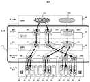
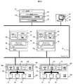
図1は、第一の実施の形態における計算機システムの構成を示す。計算機システムは、DBMSが稼動し記憶装置を使用する計算機(以下「ホスト」)70、計算機システムの管理を行う計算機(以下「システム管理サーバ」)72、バーチャリゼーション機能を有する仮想化スイッチ60、及び記憶装置50を有する。各々の装置はネットワーク46に接続され、相互に通信できる。
【0024】
ホスト70、仮想化スイッチ60、及び記憶装置50間は、通信線(以下「I/Oパス」)40で互いに接続される。ホスト70と記憶装置50の間のI/O処理は、I/Oパス40を用いて行われる。尚、I/Oパス40は、装置間で異なる物理媒体や異なるプロトコルでデータ転送を行う通信線が使用されても良い。また、ネットワーク46とI/Oパス40は同一の通信線でも良い。
【0025】
記憶装置50は、制御装置52と少なくとも1台のディスク装置54を有し、これらの装置間は内部バス56で接続される。制御装置52は、管理部108a、管理情報10a及びキャッシュ14aを有する。
【0026】
記憶装置50は、ディスク装置54が有する物理記憶領域を仮想化して1又は複数の論理ディスク装置208を外部装置に対して提供する。提供される論理ディスク装置208は、ディスク装置54と一対一に対応しても良いし、複数のディスク装置54から構成される記憶領域と対応していても良い。
【0027】
管理情報10aは、記憶装置50を管理するために保持する情報である。
【0028】
キャッシュ14aは、記憶装置50が提供する記憶領域内の一部データを一時的に保存しておくメモリである。なお、必ずしもキャッシュ14aが存在する必要はない。
管理部108aは、管理情報10aを用いて、論理ディスク装置208とディスク装置54が有する物理記憶領域との間のアドレス変換を制御する。また、記憶装置50がリモートコピー機能やスナップショット機能を有する場合には、その機能の設定も管理情報10a内に保持する。更に、DBに関する情報も管理情報10a内に保持し、キャッシュ14aへのデータの先読み制御やディスク装置54に対するデータの記憶位置の最適化処理等に利用する。
【0029】
また、管理部108aは、ネットワーク46を介して外部から受信した指示に従って、論理ディスク装置208に属するデータのディスク装置54における記憶位置を動的に変更する。「動的に変更する」とは、「システムの処理を中断することなく記憶位置を変更する」ことを意味する。また、リモートコピー機能やスナップショット機能の設定や制御はネットワーク46を介して外部から行う。
【0030】
尚、記憶装置50の管理部108aは、必ずしもデータ記憶位置を動的に変更しなくてもよい。また、リモートコピー機能やスナップショット機能はなくてもよい。
【0031】
仮想化スイッチ60は、制御部62を有する。制御部62は、管理部108b、管理情報10b及びキャッシュ14bを有する。
仮想化スイッチ60は、管理部108bを用いて、仮想化スイッチ60に接続される装置から提供される論理ディスク装置208を認識し、認識した論理ディスク装置208が有する記憶領域を仮想化した仮想ボリューム206を他の装置に提供する。
【0032】
管理情報10bは、仮想化スイッチ60を管理するための情報である。
【0033】
キャッシュ14bは、仮想化スイッチ60が提供する記憶領域内の一部データを一時的に保存しておくメモリである。なお、必ずしもキャッシュ14bが存在する必要はない。
管理部108bは、管理情報10bを用いて、仮想ボリューム206と論理ディスク装置208との間のアドレス変換を制御する。また、仮想化スイッチ60がリモートコピー機能やスナップショット機能を有する場合には、その機能の設定も管理情報10b内に保持する。更に、DBに関する情報も管理情報10b内に保持し、キャッシュ14bへのデータの先読み制御等に利用する。
【0034】
また、管理部108bは、ネットワーク46を介して外部から受信した指示に従って、仮想ボリューム206の論理ディスク装置208における記憶位置を動的に変更する。また、リモートコピー機能やスナップショット機能の設定や制御はネットワーク46を介して外部から行う。
【0035】
尚、仮想化スイッチ60の管理部108bは、必ずしもデータ記憶位置を動的に変更しなくてもよい。また、リモートコピー機能やスナップショット機能はなくてもよい。
【0036】
ホスト70は、CPU及びメモリを有し、CPUは、オペレーティングシステム(OS)80、DBMS88、及び管理エージェントプログラム106等のプログラムを実行する。OS80には、ボリュームマネージャ84が含まれる。また、OS80は、ファイルに対するソフトウエアインターフェースと同じファイルI/Oインターフェイスで、仮想ボリューム206等の記憶領域に直接アクセスできるローデバイス機構を保持する。
【0037】
DBMS88は、記憶装置50が提供する記憶領域に格納されたデータを使用する。DBMS88は、データ構造の定義情報やデータ構造のデータ記憶位置の管理情報等、DBMSの管理に必要な情報であるスキーマ情報16を保持する。なお、図中にはホスト70上にDBMS88は1つしか存在しないが、複数のDBMS88が同一計算機上で動作しても本実施の形態を適用できる。
【0038】
ボリュームマネージャ84は、ホスト70が、他の装置が提供する仮想ボリューム206あるいは論理ディスク装置208を認識し、それらに属する1つ以上の記憶領域を組み合わせた少なくても1つの仮想的な論理ボリューム204をDBMS88に提供するために、ホスト70のCPUが実行するプログラムである。これらのプログラムは、ネットワークあるいは記憶媒体を用いてホスト70にインストールされる。
【0039】
ボリュームマネージャ84は、管理情報10cを用いて論理ボリューム204と仮想ボリューム206又は論理ディスク装置208との対応関係を管理する。また、ボリュームマネージャ84がリモートコピー機能やスナップショット機能を有する場合には、その機能の設定も管理情報10c内に保持する。更に、ボリュームマネージャ84が、データ記憶位置の動的変更機能を有しても良い。
【0040】
記憶装置50、仮想化スイッチ60、及びボリュームマネージャ84(以下、これらをまとめて「仮想化機構」と称する)は、各々論理ボリューム204、仮想ボリューム206、論理ディスク装置208(以下、これらをまとめて「仮想構造」と称する。また、仮想構造にディスク装置54を加えたものをまとめて「管理構造」と称する)を動的に作成・領域拡張・削除する機能を有する。ここで、「動的に作成・領域拡張・削除」するとは、計算機システムの動作を停止せずに仮想構造を作成・領域拡張・削除することを指す。
【0041】
管理エージェントプログラム106は、データマッピングの動的変更、仮想構造の作成・領域拡張・削除等、システム管理サーバ72から受けた指示をボリュームマネージャ84に対して発行する際に実行される。また、ボリュームマネージャ84がシステム管理サーバ72へ情報を送信する際にも本プログラムが実行される。更に、システム管理サーバ72が作成した処理スクリプトをホスト70で実行する際にも本プログラムが実行される。なお、DBMS88やOS80が管理エージェントプログラム106の機能を有してもよい。
【0042】
システム管理サーバ72は、CPU及びメモリを有する。メモリには、システム管理プログラム100及びシステム管理情報18が保持される。システム管理プログラム100は、システム管理サーバ72が有する機能を実現するプログラムであり、各DBのデータ構造等を管理するDB管理部102とシステム内の記憶領域の設定管理を行う記憶領域管理部104とを含む。システム管理情報18は各DBのデータ構造に関する情報やシステム内の記憶領域の管理に用いる情報を含む。
【0043】
表示画面92及び入力装置94を有する管理端末90がネットワーク46で接続されている。入力装置94には、キーボード、マウス等が利用される。管理端末90はシステム管理サーバ72と内部バスを用いて接続されてもよい。
【0044】
尚、図1では、DBシステム管理サーバ72は他の仮想化機構から独立しているが、任意の仮想化機構がシステム管理サーバ72を兼ねても良い。特に、システム管理サーバ72が提供する機能をDBMS88が有してもよい。
【0045】
説明を容易にするため、本実施の形態では、DBのデータ構造等の管理と記憶領域の管理とを1つのシステム管理プログラム100で実現している場合を説明するが、上記の管理がそれぞれ異なるプログラムとして実現されてもよい。その場合、上記の管理がそれぞれ異なる計算機や仮想化機構で実現されてもよい。
【0046】
図2は、本実施の形態におけるデータマッピングの階層構成を示す。図2では、ホスト70と記憶装置50との間に1つの仮想化スイッチ60が存在する場合を説明する。尚、以下、ある2つの階層について、DBMS88に近い方を上位、ディスク装置54に近い方を下位の階層と称する。
【0047】
図2では、DBMS88は、それが管理している表・索引・ログ等のデータ構造210を記憶しているボリュームマネージャ84が提供する論理ボリューム204に対してアクセスを行う。図2のように、あるデータ構造210のデータを複数の論理ボリューム204に分割して記憶してもよい。その一方で、本実施の形態では、1つの論理ボリューム204に記憶されるデータ構造210は1種類のみである。
【0048】
ボリュームマネージャ84は、論理ボリューム204に対するアクセスを、論理ボリューム204に対応する仮想ボリューム206の領域へのアクセスに変換する。仮想化スイッチ60は、仮想ボリューム206に対するアクセスを、対応する論理ディスク装置208の領域へのアクセスに変換する。記憶装置50は、論理ディスク装置208に対するアクセスを、論理ディスク装置208に対応するディスク装置54に対するアクセスに変換する。
【0049】
また、図示しないが、ある仮想化されたデータが、複数のホスト70に共有されてもよい。データの共有は、下位階層の仮想ボリューム206等における同じ記憶領域が、複数の上位階層の仮想化機構(仮想化スイッチ60等)に参照されることにより実現される。
【0050】
なお、仮想化スイッチ60は1段に限られるものではなく、任意の段数が存在してもよい。また、ホスト70のボリュームマネージャ84が存在しない/使用されない、仮想化スイッチ60が存在しない、及び記憶装置50が論理−物理記憶領域変換機能を保持せずディスク装置54の記憶領域をそのまま外部に提供する等の場合にも、システム全体で仮想化機構が1段以上存在する場合には本発明の実施の形態を適用できる。
【0051】
なお、記憶装置50が論理−物理記憶領域変換機能を保持しない場合、記憶装置50がどのようなディスク装置54を保持しているかに関する情報のみがシステム管理サーバ72には必要であり、その場合にはシステム管理サーバ72と記憶装置50との間のマッピング情報の遣り取りは不要であり、必ずしも記憶装置50はネットワーク46に接続される必要はない。
【0052】
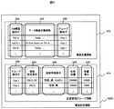
図3は仮想化機構が保持する管理情報10bのデータ構造を示す。記憶装置50の管理情報10aも図3と同様の構成である。管理情報10bは、マッピング情報302、機能設定情報304、DB構造情報306を含む。
【0053】
マッピング情報302は、データの階層関係を示す情報を格納し、エントリ312〜322を有する。エントリ312には、当該管理情報10bを有する仮想化機構が、上位階層に対して提供する仮想構造を示す上位仮想構造識別子を示す情報が格納される。
【0054】
エントリ314には、上位仮想構造識別子に対応する仮想構造における記憶領域を示す上位構造内ブロック番号を示す情報が格納される。エントリ316には、当該管理情報を有する仮想化機構に記憶領域を提供する下位の仮想化機構を示す下位仮想化機機構識別子を示す情報が格納される。なお、記憶装置50内の管理情報10aではこのエントリは存在しない。エントリ318には、下位仮想化機構識別子に対応する仮想化機構が提供する管理構造の識別子(記憶装置50内の管理情報10aではディスク装置54の識別子)である下位管理構造識別子を示す情報が格納され、エントリ320には、下位管理構造識別子に対応する管理構造における記憶領域を示す下位構造内ブロック番号を示す情報が格納される。
【0055】
上位仮想構造識別子が“Free”であるエントリ322は、当該管理情報を有する仮想化機構がその領域を利用できる状態にあるが、まだ上位階層の仮想化機構に対して提供されていない下位階層の記憶領域を示す。仮想化機構がデータ記憶位置の動的変更機能を有する場合には、この下位階層の記憶領域に対してコピーを伴うデータ移動処理を行う。
【0056】
機能設定情報304は仮想化機構がスナップショット機能やリモートコピー機能を有する場合にその機能の設定管理のための情報であり、それらの機能を持つ仮想化機構の管理情報10bにのみ含まれる。機能設定情報304はエントリ312,334,336を有する。
【0057】
エントリ312は前述したものと同じである。エントリ334はエントリ312で示された上位仮想構造に対して設定された機能を示す設定機能に関する情報が格納される。エントリ336には、エントリ334で示された機能に関する詳細な情報である機能設定詳細が記憶される。
【0058】
例えば、設定機能がスナップショット機能の場合には、そのスナップショット作成先の上位仮想構造に関する情報や、他の上位仮想構造と同期してスナップショットを作成する場合に同期を取るべき上位仮想構造の情報を保持する。設定機能がリモートコピー機能の場合には、リモートコピーを作成するコピー先に関する情報や、コピー時に書き込み順序を保証すべき複数の上位仮想構造のグループに関する情報が格納される。
【0059】
DB構造情報306は、記憶装置50や仮想化スイッチ60において、キャッシュ14bの管理やデータ記憶位置の最適化をDBに関する情報を用いて行う場合に利用する情報であり、全ての仮想化機構で必ずしも保持する必要はない。DB構造情報306はエントリ342〜348を有する。
【0060】
エントリ342には、記憶されるデータを保持するDBを識別するDB識別子が格納される。エントリ344には、そのデータが所属するデータ構造を識別するデータ構造識別子が格納される。エントリ346には、そのデータ構造の種類に関する情報である構造種別が格納される。
【0061】
エントリ348には、エントリ342,344で示されるDBとデータ構造に対応するデータが記憶される上位仮想構造である構成上位仮想構造に関する情報が格納される。ここには、必要に応じて、例えばシーケンシャルアクセス時のアクセス順等に関する情報も付加された情報が格納される。
【0062】
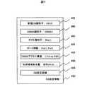
図4はシステム管理サーバ72が保持するシステム管理情報18のデータ構造を示す。システム管理情報18は、I/Oパストポロジ情報360、DBMS管理情報361、記憶装置構成情報362、構造設定集約情報364、仮想化機構管理情報366、DB領域管理情報368、DBデータ領域設定情報370を含む。
【0063】
I/Oパストポロジ情報360には、システム管理サーバ72が管理する計算機システム内の機器間の接続関係、特にI/Oパス40に関する情報が格納される。
【0064】
DBMS管理情報361には、システム内に存在するDBMS88に関する情報、例えば、DBMSがどのホスト上で動作しているか、あるいは、DBMS毎に存在する制約条件等が格納される。
【0065】
記憶装置構成情報362には、記憶装置50において、固定的に割り当てられたもの、例えば、ディスク装置54により構成されるディスク装置群の冗長化方式やディスク装置54の性能に関する情報等、が格納される。
【0066】
構造設定集約情報364は、システム管理サーバ72が管理する計算機システム内に存在するDBのデータ構造の設定情報が格納される。構造設定集約情報364はエントリ342,380〜384が含まれる。
【0067】
エントリ342は前述の通りである。エントリ380には、対応するDBを管理するDBMS88を識別する情報であるDBMS識別子が格納される。エントリ382には、エントリ342に対応するDBを管理するDBMS88が実行されるホスト70の識別子であるホスト識別子が格納される。エントリ384には、エントリ342で識別されるDB毎に、そのDBに関するデータ構造の設定情報である構造設定情報420が格納される。構造設定情報420の詳細は後述する。
【0068】
仮想化機構管理情報366は、システム管理サーバ72が管理する計算機システム内の仮想化機構に関する情報が保持される。仮想化機構管理情報366にはエントリ386〜390が含まれる。
【0069】
エントリ386には、仮想化機構を識別する仮想化機構識別子が格納される。エントリ388には、エントリ386で識別される仮想化機構が保持する機能や、それが提供する仮想構造の制約に関する情報である機構詳細が格納される。エントリ390には、エントリ386で識別される仮想化機構が保持する管理情報10bの一部が仮想化機構管理情報として格納され、少なくとも、対応する管理情報10b中のマッピング情報302が格納される。更に、仮想化機構が各種機能を保持している場合は、その機能に関する機能設定情報304が格納される。
【0070】
DB領域管理情報368にはシステム管理サーバ72が管理する計算機システム内に存在するDBの領域管理に必要な情報が格納されている。DB領域管理情報368には、エントリ342,382,402〜408が含まれる。
【0071】
エントリ342,382は前述の通りである。エントリ402には、エントリ382で識別されるホストが、データアクセスのために利用するI/Oパス40やネットワーク46への接続ポートに関する情報であるポート情報402が格納される。
【0072】
エントリ404は領域管理を行う際のラベルとして利用する分類である。分類には、エントリ342で識別されるDB全体を示す“全体”、スナップショット機能が割り当てられる領域を示す“SS”、リモートコピー機能が割り当てられる領域を示す“RC”等が利用される。
【0073】
エントリ342で識別されるDBに対して、エントリ404で示される分類に従った領域毎に、エントリ406には、各分類が利用可能な利用量上限設定値や現在実際に利用している実利用領域量に関する情報である利用量管理情報が格納される。エントリ408には、各分類の領域に関して管理する際に必要となる詳細な設定に関する情報である詳細設定情報408が格納される。詳細設定情報408の例としては、以下のものがある。
1)対応するDBを管理するDBMS88が認識する仮想構造の種類やその最大サイズ、最大数等、仮想構造に関する情報。
2)指定されたスナップショットやリモートコピー機能を実現するための仮想化機構を制限する場合の制約条件。
3)リモートコピー機能におけるコピー先に関する情報。特に、システム管理サーバ72の管理外の計算機システムに対してリモートコピーを実施する場合のコピー先。
【0074】
なお、エントリ402,404,406,408に格納される情報を複数のDBで共有し、複数のDBを一括して管理することもできる。
【0075】
DBデータ領域設定情報370には、システム管理サーバ72が管理する計算機システム内に存在するDBのデータ構造に関して、DBがどのように記憶領域が割り当てられたかを管理するために必要な情報が格納されている。DBデータ領域設定情報370にはエントリ342,344,410〜414が含まれる。
【0076】
エントリ342,344は前述の通りである。エントリ342,344で識別されるDBのデータ構造に関する情報として、エントリ410には、DBMS88がデータ構造を格納する記憶領域を管理する外部記憶領域管理構造に関する情報が格納される。エントリ412には、DBがどの記憶領域に割り当てられたかに関するデータ記憶先の情報が格納される。ここでは、エントリ342に対応するDBを管理するDBMS88が直接利用する仮想構造に関する情報が保持される。エントリ414には、DBのデータ構造に対して、エントリ412に対応する領域に関して、その領域にスナップショット等の機能が設定されている場合に、設定された機能がどこで実現されているかに関する情報である機能設定情報414が格納される。機能設定情報414の中には、更に、スナップショット取得時の同期やリモートコピーの書き込み順序を保証するグループに関する情報も機能に関する情報の一部として格納しておく。
【0077】
図5は構造設定情報420のデータ構造を示す。構造設定情報420には、エントリ344,422〜430が含まれる。なお、構造設定情報420に対応するDBを識別する情報は別途指定される。
【0078】
エントリ344は前述の通りである。エントリ344に対応するデータ構造に関する情報として以下のものを含む。エントリ422には、そのデータ構造を定義するために必要十分なデータ構造定義情報が格納される。エントリ424には、設定を要求する機能が存在する場合に機能に関する情報である機能設定要求が格納される。このとき、スナップショット機能やリモートコピー機能等で複数のグループを作成して管理する必要がある場合には、機能の識別情報も含める。特に機能の設定を求めない場合には無効値が格納される。エントリ426には、高性能性やRAID1構成等、エントリ344に対応するデータ構造を格納する記憶領域に対して要求する特徴に関する情報である領域特徴要求が格納される。エントリ428には、エントリ344に対応するデータ構造用に最初に割り当てる記憶容量に関する情報である初期容量が格納される。エントリ430には、エントリ344に対応するデータ構造用に記憶領域を拡張する際の記憶容量の増分である容量増分が格納される。なお、エントリ426,428,430はそれぞれ存在しない、もしくは無効値(設定なし)を保持していてもよい。
【0079】
以下、DBの領域管理に関する処理手順を説明する。以下の手順では、管理者からの指示は管理端末90から行う。システム管理サーバ72からの指示はネットワーク46を介して以下のように行う。記憶装置50、仮想化スイッチ60に対しては直接指示を出す。ボリュームマネージャ84に対しては管理エージェントプログラム106を介して指示を出す。DBMS88に対しては、直接指示を出すか、あるいは、処理スクリプトを作成し、それをDBMS88が実行されているホスト70上で管理エージェントプログラム106を介して実行する。
【0080】
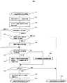
図6は新規DBを作成する処理手順を示す。説明を簡単にするため、本手順ではエラーに関する処理は省略する。図6の左側は管理者が行う処理を示し、右側はシステム管理サーバ72が行う処理を示す。尚、下記処理中にエラーが発生した場合は、処理を中断し、可能であれば元の構成に戻す処理が行われる。
【0081】
管理者は、新規DB作成処理を開始する。なお、この時点でシステム管理情報18は最新のデータを保持しているものとする(ステップ1001)。続いて、新規DBを管理する際に新規DBが守るべき各種条件を設定する。各種条件の設定は、管理者がDB設定情報450をシステム管理サーバ72に与えることにより行う(ステップ1002)。
【0082】
図7はステップ1002で指定されるDB設定情報450のデータ構造を示し、DB設定情報450には、エントリ380,382,402,452〜458が含まれる。
【0083】
エントリ452に、これから新規に作成する新規DBを識別するために利用する新規DB識別子が格納される。システム管理サーバ72では、この値をDB識別子として利用する。エントリ380,382,402は前述の通りであり、新規DBを管理するDBMS88とそれが実行されるホスト、そして、そのホストが利用するI/Oポートを指定する。エントリ454には、エントリ380で識別されるDBMS88が認識してアクセスを行う仮想構造の種類と仮想構造を提供すべき仮想化機構の情報であるDBMSアクセス構造が格納される。
【0084】
エントリ456には、新規DBに対して最初に利用可能として割り当てる記憶容量に関する情報である初期領域割当量を格納する。エントリ456に格納された情報を基にDB領域管理情報368中の利用量管理情報を設定するため、各種機能を利用する際にはその分類を考慮した初期領域割り当て量を設定する。なお、他のDBと共通に管理する場合、共通管理するDBのDB識別子を格納する。
【0085】
エントリ458には、その他新規DBに関する情報であるDB設定詳細を格納する。特に、システム管理サーバ72の管理外の計算機システムに設定する場合も含む、リモートコピー機能を設定する場合には、必要に応じてコピー先の設定に関する情報をエントリ458の中に含めておく。また、管理者が設ける各種制約条件もこの中に格納する。
【0086】
システム管理サーバ72は、受け取ったDB設定情報450を基に必要な情報をシステム管理情報18に設定する。まず、構成設定集約情報364中に新規DBのエントリを作成する。続いて、DB管理情報368中に新規DBの領域管理などの情報を格納する。このとき、各種機能に関する情報がエントリ458に保存されている場合には、その情報をエントリ408の対応部分に記憶する(ステップ1003)。
【0087】
次に、管理者は新規DBのDB識別子とともに構造設定情報420をシステム管理サーバ72に与える。このとき、特に要求が存在しない場合にはエントリ424,426,428,430はなくてもよい(ステップ1004)。なお、ステップ1002とステップ1004の処理を同時に行ってもよい。
【0088】
新規DB作成と同時に新規にDBMS88を導入する場合には、ログやスキーマ情報16等のようなDBMS88自身の管理情報の記憶領域設定方法の情報が必要になる。これらの情報は、DB設定情報450中のDB設定詳細458もしくは構造設定情報420に含めて管理者が設定する、もしくは、DBMS管理情報361中に標準的な設定方法を記憶してそれを利用するものとする。以降、新規DBMS88導入時の管理情報も他のデータ構造と同一に扱う。
【0089】
システム管理サーバ72は、受け取ったDB識別子と構造設定情報420を基に必要な情報をシステム管理情報18に設定する。まず、構造設定情報420を構成設定集約情報364中の対応部分に記憶する。続いて、指定されたDB識別子と構造設定情報420中のエントリ344とから、新規DBに対応するエントリをDBデータ領域設定情報370中に設定する(ステップ1005)。
【0090】
続いて、システム管理サーバ72は、新規DBのデータを記憶する仮想構造の構成を決定する。つまり、データ構造毎に、DB設定情報450中のエントリ454で指定されたDBMS88がアクセスする仮想構造の構成を決定する。
【0091】
作成する仮想構造は、更に下位に存在する仮想化機構が提供する記憶領域から構成され、その記憶領域は複数の仮想化機構を経由してディスク装置54上の領域に割り当てられる。そこで、I/Oパストポロジ情報360、記憶装置構成情報362、仮想化機構管理情報366を参照しながら、DB設定情報450や構造設定情報420で指定された条件や機能を満たすように、いずれかの仮想化機構の管理情報10b中のマッピング情報302中で“Free”が設定された領域に対応するディスク装置54上の記憶領域から最適なものを求め、求めた記憶領域からデータ構造を記憶する仮想構造の構成を決定する。このとき、仮想化機能間のマッピングも同時に考える。なお、構造設定情報420中のエントリ428で指定された初期容量が、決定した仮想構造の大きさとなる。初期容量の値が指定されていない場合、システム管理サーバ72は予め定められたデフォルト値を用いる。このとき、指定された大きさに1つの仮想構造では満たない場合には、複数の仮想構造を割り当てる。
【0092】
上記処理で調べる条件は、優先順に以下の通りである。同順位の部分が多数ある場合には、更に下位の条件を調べて仮想構造の構成を決定する。
1)記憶領域や各種機能を実現する仮想化機構に関する指定(制約条件)がある場合に、それを満たすように仮想構造の構成を作成する。
2)データ構造を格納する領域に対して要求された機能を実現可能な仮想化機構を求め、実現可能な仮想化機構を経由するように仮想構造の構成を作成する。
3)データ構造を格納する領域に対して要求された特徴を満たすように仮想構造の構成を作成する。
4)各仮想化機構において連続した仮想構造を確保できる場合には、連続した仮想構造を優先して、データ構造を記憶する仮想構造の構成要素とする。
【0093】
基本的に、上記条件1)、2)を満たすような考えうる全ての仮想構造の構成を把握し、その中で条件3)、4)を尺度に最適なものを探し出す。なお、1つでもデータ構造に対して条件1)、2)を満たすような仮想構造を作成できない場合には、エラーが発生したとする。
【0094】
1つのデータ構造に対して複数の仮想構造を割り当てるケースが存在する。そのようなデータ構造に対して機能を設定する必要がある場合、複数の仮想構造を利用しても要求された機能が実現できるか、例えば、複数の仮想構造間で、スナップショット機能で同期が取れるか、あるいは、リモートコピー機能でコピー時に書き込み順序が保証されるか等を確認する(ステップ1006)。
【0095】
続いて、システム管理サーバ72は、求めた仮想構造の構成を実現するために、仮想化機構に対してそれらを作成する指示を出す。この作成指示は、下位に存在する仮想化機構から順に行う。なお、新たに作成する仮想構造が記憶装置50の管理情報10a中のマッピング情報302で“Free”となっていない領域も利用する場合には、新規仮想構造の作成に先だって、“Free”となっていない領域に関係する仮想化機構に対して“Free”となっていない領域を開放する指示を出す。また、ボリュームマネージャ84が存在しない場合には、管理エージェントプログラム106を介して、作成した仮想ボリューム206もしくは論理ディスク装置208を認識するようOS80に指示を出す。
【0096】
その後、DBデータ領域設定情報370中のデータ記憶先を記憶するエントリ412の対応する部分に作成した仮想構造の情報を設定し、また、DB領域管理情報368中のエントリ406に格納されている利用量管理情報を実際に割り当てた値に更新する(ステップ1007)。
【0097】
続いて、システム管理サーバ72は、データ構造に指定された機能を実現するために、仮想化機構に対して機能設定の指示を出す。機能を設定する仮想化機構は、ステップ1006で仮想構造の構成を求める際に条件として設定したものである。ここでは、必要に応じて、機能実現に必要な記憶領域の確保や、事前に与えられた情報を基にしたシステム管理サーバ72の管理外の計算機システムとの設定情報交換を行う。その後、DBデータ領域設定情報370中の機能設定情報を記憶するエントリ414の対応する部分に設定した機能に関する情報を設定する(ステップ1008)。
【0098】
最後に、システム管理サーバ72は、DBMS88に対して、対応する作成した仮想構造にデータ構造のデータを記憶するように新規DBの作成を指示する。
【0099】
まず、新規DBを管理するDBMS88を新規に導入する場合には、導入処理実行スクリプトを作成する。このとき、ログやDBMSの管理情報を記憶する領域に利用する仮想構造も作成されているので、作成された仮想構造を利用するような指示を含むようにする。続いて、DB設定情報450内のエントリ382で指定されたホスト識別子を持つホスト上で作成したスクリプトを実行し、DBMS88を新規に導入する。
【0100】
続いて、新規DBのスキーマを、新規DBを管理するDBMS88に与えて、新規DBを作成する。新規DBのスキーマは、構造設定情報420内のエントリ422に格納されているデータ構造定義情報と、必要に応じてDB設定情報450内のエントリ458に格納されたDB設定詳細により与えられた設定を基に作成される。ここで注意すべき点は、データ構造が、それに対応するように作成した仮想構造に記憶されるようにすることである。現在、表・索引等のデータ構造と外部記憶領域管理構造が独立しているDBMSが多い。このようなDBMSに対しては、個々のデータ構造に対して独立した外部記憶領域管理構造を割り当てるようにし、異なるデータ構造は異なる外部記憶領域管理構造を利用するようにする。上記の外部記憶領域管理構造に対して、データ構造に対応する作成した仮想構造を割り当てるようにする。割り当てた外部記憶領域管理構造に関する情報は、DBデータ領域設定情報370中の外部記憶領域管理構造に関する情報を格納するエントリ410の対応部分に記憶される(ステップ1009)。
【0101】
新規DB作成処理を完了し、管理者はその報告を受ける(ステップ1010)。その後、必要であればシステム管理情報18を最新のデータに更新する。
【0102】
図8はDBデータの記憶領域を拡張する処理手順を示す。本処理はシステム管理サーバ72が行う。
【0103】
まず、システム管理サーバ72がデータ構造の記憶領域を拡張する処理の開始要求を受け取る。その要求契機は2つ考えられる。1つは管理者が管理端末90から指示を出す場合である。もう1つはDBMS88がデータ記憶領域不足を検知した場合である。このときDBMS88がシステム管理サーバ72に領域拡張要求を出してもよい。また、ボリュームマネージャ84が領域拡張の必要性を把握し、管理エージェントプログラム106を介してシステム管理サーバ72に領域拡張要求を出してもよい。ボリュームマネージャ84が領域拡張の必要性を把握する方法としては、DBMS88が専用のアプリケーションプログラムインターフェイスを用いて領域拡張の必要性を伝える方法や、ボリュームマネージャ84が仮想構造の記憶領域未割り当て部分への書き込みを検知する方法等がある(ステップ1101)。
【0104】
続いて、領域の拡張が要求された仮想構造を認識し、要求された仮想構造に対応するデータ構造に関する情報を把握する。これは、DBデータ領域設定情報370中のデータ記憶先を記憶するエントリ412を検索して、対応するDB識別子とデータ構造識別子を求めることにより実現される(ステップ1102)。
【0105】
続いて、対応するDBやデータ構造に対して設定されている各種条件や機能を確認する。これは、求めたDB識別子とデータ構造識別子を用いて、構造設定集約情報364、DB領域管理情報368、DBデータ領域設定情報370の対応する部分を参照することにより行なわれる(ステップ1103)。
【0106】
次に、領域拡張後も記憶領域の利用量上限値を超過するかどうかを確認する。領域拡張量は、構造設定集約情報364内に格納されている各DB毎の構造設定情報420中のエントリ430に容量増分として保持されている。領域拡張量の値が存在しない場合には、予め定められたデフォルト値を領域拡張量とする。記憶領域利用量の制約を管理する情報は、DB領域管理情報368中のエントリ406に利用量管理情報として記憶されている。このとき、データ構造に対してある機能が設定されている場合には、設定されている機能に対する利用量上限値も確認する。上記の利用量上限値をすべて超過しない場合には、ステップ1107に進み、1つでも超過するものがある場合にはステップ1105に進む(ステップ1104)。
【0107】
次に、管理端末90を介して、管理者に、あるデータ構造のデータを格納する領域を拡張しようとしたが利用量上限値を超過する旨を通知し、利用量上限値を更新するかどうかを確認する。管理者が更新する指示を出した場合にはステップ1106に進む。更新をしない指示を出した場合には、ステップ1130に進み、領域拡張処理失敗として処理を異常終了する(ステップ1105)。
【0108】
次に、領域利用量の上限値を更新する。管理者から領域利用量上限の更新値を受け取り、DB領域管理情報368中のエントリ406に格納されている利用量管理情報中の領域利用量の上限値を新しい値に更新する(ステップ1106)。
【0109】
続いて、DBMS88が、現在データ構造の記憶先として利用中の仮想構造の記憶領域が拡張可能かどうかを調べる。これは、仮想化機構管理情報366中のエントリ388に格納されている仮想化機構の各種制約や、DB領域管理情報368中のエントリ408に格納されているDBの記憶領域管理のための詳細設定情報中の各種制約条件を確認することにより行なわれる。ここで、拡張可能とは、DBMSがアクセスする仮想構造を構成する各層における管理構造が、いずれも記憶領域が拡張可能な状態であることを指す。仮想構造の記憶領域を拡張可能の場合にはステップ1120に進む。拡張不可能な場合にはステップ1108に進む(ステップ1107)。
【0110】
ステップ1107で仮想構造の記憶領域が拡張可能な場合、DBMSがアクセスする仮想構造を構成する全ての仮想構造が拡張可能であり、仮想構造の記憶領域を拡張するように対応する仮想化機構に指示を出す(ステップ1120)。
【0111】
ステップ1107で仮想構造の記憶領域が拡張不可能な場合は、DBMS88がデータ構造を記憶するために利用する仮想構造を新規に作成する。新規に作成する仮想構造の構成の決定は、ステップ1006で述べた方法と同一である。その際に1つのデータ構造を複数の仮想構造に分割する際の注意事項を述べたが、既に存在する仮想構造と新規作成した仮想構造の組でもこの注意事項を満たす必要がある。その後、ステップ1007,ステップ1008と同様に新規に仮想構造を作成し、作成した仮想構造に必要な機能を設定する(ステップ1108)。
【0112】
ステップ1120、ステップ1108の処理は失敗する可能性がある。そこで、ここでそれらの処理が成功したかを確認する。成功した場合にはステップ1110に進む。失敗した場合には、ステップ1130に進み、領域拡張処理失敗として処理を異常終了する(ステップ1109)。
【0113】
データ構造を記憶するために利用する記憶領域の拡張先の確保に成功した場合には、拡張先を利用可能とするためにDBMS88に認識させる必要がある。そこで、既存仮想構造の記憶領域を拡張した場合にはその旨をDBMS88に伝える。また、新規にデータ記憶用の仮想構造を作成した場合には、作成した仮想構造を、拡張が必要なデータ構造に対応する外部記憶領域管理構造に対して追加するようにDBMS88に指示を出す(ステップ1110)。その後、データ構造記憶領域の拡張処理を正常終了する(ステップ1111)。
【0114】
DBのデータ記憶領域の開放はDBが削除された際に以下のように行う。
【0115】
まず、DBMS88においてDBが削除されたことを確認する。これを確実にするため、基本的に、管理者がシステム管理サーバ72を介してDBMS88にDBの削除を指示する。
【0116】
次に、システム管理サーバ72は、削除されたDBのデータを記憶している仮想構造に設定されている機能を解除するよう対応する仮想化機構に指示し、その後に指示された仮想構造を削除するように仮想化機構に指示する。
【0117】
最後に、システム管理サーバ72はシステム管理情報18中で削除されたDBに対応する情報を全て削除する。
【0118】
システム管理サーバ72は、DBのデータ構造のマッピングや、データ構造のデータに対する各種機能の設定情報を保持している。そこで、特定のDBやDBのデータ構造のみに対するバックアップ等の処理を行う場合には、この設定情報を用いて処理を行うべき領域を把握できる。特に、ある仮想構造には1つのデータ構造のデータのみしか記憶されていないため、不要なデータを扱うことなく効率的に処理を実施できる。
【0119】
本実施の形態では、1つの仮想構造内に1つのデータ構造のデータのみが格納される。このような格納形態を利用すると、仮想化機構において、以下のような最適化を行うことができる。
【0120】
記憶装置50や仮想化スイッチ60がキャッシュ14を有する場合には、その制御に1つの仮想構造内に存在するデータは同一データ構造のみであることが利用できる。例えば、表データへの全走査を行う場合、表データを記憶する仮想構造をシーケンシャルにアクセスすることが期待できるため、先読み予測の精度を高められる。また、データ構造毎にデータの再利用性等のアクセス特性が異なるため、仮想構造毎にグループ化して、キャッシュ14にデータを保持する割合を変化させる等、キャッシュ14のデータ保持制御を最適化することによりキャッシュヒット率を向上できる。
【0121】
更に、記憶装置50ではディスク装置54に対するデータの配置の最適化を行うことができる。例えば、ある表データと表データに対応するB−Tree形式の索引データは同時にアクセスされる可能性が高い。そこで、これらのデータは異なるディスク装置54上に配置するのがよい。また、前述の表データへのシーケンシャルなアクセスを考えて、表データを保持する仮想構造の記憶領域を、ディスク装置54上のある一定量以上の物理的に連続した領域に割り当てる。これらのデータ配置方法は、仮想構造作成時の優先順の尺度としても利用できる。
【0122】
そこで、システム管理サーバ72は、管理情報10b中にDB構造情報306を有する仮想化機構に対しては、ステップ1007やステップ1108で新規に仮想構造を作成した際に、作成した仮想構造が保持するデータとDBデータとの対応を示す情報を与え、仮想化機構はDB構造情報306中にその情報を格納する。仮想化機構は、格納された情報を用いて上述の最適化を実施できる。
<第二の実施の形態>
第二の実施の形態では、バーチャリゼーション機能を持つ機器やソフトウェアにおいて、設計されたDBのスキーマを基に、表・索引・ログ等のような、DBのデータ構造を記憶領域管理のためにグループ化し、それぞれに異なる仮想ボリューム等を割り当てる。そして、DBMSに対して、グループ化されたDBのデータ構造のデータを対応する仮想ボリューム等に格納するようなDBを作成する指示を出す。これにより、特定の仮想ボリューム等には特定のデータ構造のグループに属するデータのみが記憶される。上記のグループ化を用いてDBのデータ構造に対して割り当てられたスナップショットやリモートコピーの機能設定を自動的に行う。本実施の形態は、仮想ボリューム作成に関する制約(特にスナップショットやリモートコピー等の機能を設定できる仮想ボリューム数等に関するもの)が厳しい計算機システムに対して適応できる。
【0123】
第二の実施の形態はかなりの部分が第一の実施の形態と同一である。以下、第二の実施の形態と第一の実施の形態が異なる部分に関して説明する。
【0124】
第二の実施の形態の計算機システムの構成は、第一の実施の形態の構成とほとんど同一である。更に、ホスト70内のOS80がファイルシステムを有し、ファイルシステムが提供するファイルをDBMS88が利用する場合にも本実施の形態に当てはめることができる。この場合、ファイルシステムはそれが管理する記憶領域を拡張できる必要がある。また、ファイルシステムへの指示やファイルシステムからの要求は管理エージェントプログラム106を介して行う。
【0125】
第二の実施の形態におけるデータマッピングの階層構成の違いは以下の通りである。第一の実施の形態では、1つの仮想構造に対して1つのデータ構造のデータのみが記憶された。しかし、本実施の形態においては、1つの仮想構造に対して、記憶領域管理のために同一のグループ(以下、このグループを「記憶管理グループ」と称する)にまとめられたデータ構造のデータが記憶される。
【0126】
OS80内のファイルシステムが提供するファイルをDBMS88が利用する場合は、ファイルシステムはある論理ボリューム上に作成される。このとき、ファイルシステム内に、DBMS88が利用する複数のファイルを配置できる。本実施の形態では、ある論理ボリュームのデータには同一の記憶管理グループに属するデータ構造のデータのみが記憶される必要がある。従って、あるファイルシステムが提供するファイル群に関しても、必ずある1つの記憶管理グループに属するデータ構造のデータを保持する。
【0127】
第二の実施の形態で利用される情報のデータ構造は、第一の実施の形態と比較して以下の点が異なる。
【0128】
仮想化機構が保持する管理情報10bにおいて、1つの仮想構造の中には、ある記憶管理グループに属する複数のデータ構造のデータが記憶されるため、DB構造情報306を保持する場合には、エントリ348に格納される情報は、仮想構造の識別子とそれが仮想構造内のどの領域に記憶されるかを判別する情報とからなる。
【0129】
構造設定情報420に関しては以下の点が異なる。記憶管理グループは、特にスナップショット等の機能を設定する仮想構造に関する制約が厳しい場合に用いることを念頭においている。そこで、エントリ424に格納されている機能設定要求の中に、記憶管理グループに関する情報を含める。もしくは、構造設定情報420の代わりに構造設定情報420bを用いる。
【0130】
図9は構造設定情報420bのデータ構造を示す。図5の構造設定情報420と比較して、構造設定情報420bは記憶管理グループの識別子を格納するエントリ432を追加し、グループ識別子を用いて構造定義情報472と記憶管理グループ情報474の2つの表にデータ構造を分離する。構造定義情報472はDBのデータ構造に関する情報を保持し、エントリ344,422,432を有する。記憶管理グループ情報474は、記憶管理グループに関する情報を保持し、エントリ424〜432を有する。各エントリが保持する情報の内容は前述の通りである。
【0131】
第二の実施の形態における新規DB作成の処理手順は、第一の実施の形態と以下の点が異なる。
【0132】
図6のステップ1006では、データ構造毎に仮想構造の構成を決定していたが、記憶管理グループ毎に変更した処理を行う。なお、ステップ1004で必ずしも記憶管理グループの設定情報が全て与えられる必要はない。設定が与えられていない部分に関しては、以下に示す手順で記憶領域グループを設定する。
1)同一の機能が設定されているデータ構造をグループ化して記憶管理グループとする。スナップショットやリモートコピー機能に関して、同期要求等を必要とする複数グループが存在する場合には、複数のグループはそれぞれ異なる記憶管理グループとする。1つのデータ構造に複数の機能が設定されている場合、幾つかの機能の組を1つの機能と考える。この条件では、例えば、リモートコピー機能のコピー時に書き込み順序を保証する等のように、異なる記憶管理グループ間、つまり、異なる仮想構造間で、ある機能を一元管理する必要が出てくる。仮想化機構でこのような一元管理ができない場合にはエラーとする。
2)機能設定が要求されておらず、かつ、初期容量が予め定められた閾値以下のデータ構造に関しては、それらをまとめて初期容量が閾値を超えるようにグループ化し、それを記憶管理グループとする。
3)残りの記憶管理グループが設定されていないデータ構造に関しては、それぞれを独立した記憶領域グループとする。
【0133】
ステップ1009では、データ構造毎に外部記憶領域管理構造を用意していた点を、同一の記憶管理グループに属するデータ構造に対しては、同じ外部記憶領域管理構造に記憶されるように変更する。
【0134】
なお、OS80内のファイルシステムが提供するファイルをDBMS88が利用する場合は、更に以下のような違いがある。ステップ1007では、仮想構造を作成後、OS80に作成した仮想構造を利用するファイルシステムの作成を指示する。ステップ1009では、ある記憶管理グループに属するデータ構造を、同一のファイルシステムから提供されるファイル群にデータを記憶する複数の外部記憶領域管理構造に割り当ててもよい。
【0135】
第二の実施の形態におけるDBデータの記憶領域を拡張する処理手順は、第一の実施の形態の手順とほとんど同一である。ただし、記憶管理グループを用いているため、仮想構造は記憶管理グループに所属する複数のデータ構造に対応している点が異なる。
【0136】
なお、OS80内のファイルシステムが提供するファイルをDBMS88が利用する場合には、以下のような違いがある。
【0137】
まず、領域拡張処理の要求方法として、DBMS88がファイルを拡張しようとしてもできない場合に、システム管理サーバ72に領域拡張要求を出す方法を利用できる。
【0138】
ステップ1120では、仮想構造の拡張を完了した後にファイルシステムの拡張処理を実行する。
【0139】
ステップ1108では、新規に仮想構造を作成した後にその上にファイルシステムを作成し、ホスト70に作成したファイルシステムを認識させる。
【0140】
ステップ1110では以下の処理を行う。ステップ1120でファイルシステムを拡張した場合には、既存ファイルが拡張可能な旨をDBMS88に伝える。ステップ1108で新規にファイルシステムを作成した場合には、作成したファイルシステムにファイルを作成し、作成したファイルシステムを対応する外部記憶領域管理構造に対して追加するようにDBMS88に指示を出す。
<第三の実施の形態>
第三の実施の形態では、ファイルベースでアクセスを行う記憶装置において、設計されたDBのスキーマを基に、表・索引・ログ等のように、DBのデータ構造毎に異なるファイルを割り当てる。そして、DBMSに対してそれらのデータを対応するファイルに格納するようなDBの作成を指示する。上記の処理により、特定のファイルには特定のデータ構造に属するデータのみが記憶される。上記のファイル割当てを用いてDBのデータ構造に対して割り当てられたスナップショットやリモートコピーの機能設定を行う。
【0141】
第三の実施の形態のほとんどの部分が第一の実施の形態と同一である。以下、第三の実施の形態と第一の実施の形態が異なる部分を説明する。
【0142】
図10は、第三の実施の形態における計算機システムの構成を示す。第一の実施の形態とは以下の点が異なる。
【0143】
記憶装置50がファイルベースでアクセスを行う記憶装置50cに変更される。また、ホスト50がネットワークファイルシステム86を有するホスト70cに変更される。ホスト70cと記憶装置50c間のデータ転送はネットワーク46を用いて行うため、I/Oパス40、仮想化スイッチ60が存在しない。
【0144】
記憶装置50cでは、ファイルベースでアクセスが行われるため、制御装置52が制御装置52cに変更され、制御装置52の中に存在する管理部108aが管理部108cに変更される。
【0145】
管理部108cは、管理情報10aを用いて、ファイルとディスク装置54が有する物理記憶領域との間のアドレス変換を制御する。また、記憶装置50cがファイルやディレクトリ構造等で指定されるファイル群に対するリモートコピー機能やスナップショット機能を有する場合には、機能の設定も管理情報10内に保持する。また、DBに関する情報も管理情報10a内に保持し、キャッシュ14aへのデータの先読み制御やディスク装置54に対するデータの記憶位置の最適化処理等に利用する。
【0146】
また、管理部108cは、ネットワーク46を介して外部から受信した指示に従って、ファイルに属するデータのディスク装置54における記憶位置を動的に変更する。尚、記憶装置50cの管理部108cは、必ずしもデータ記憶位置を動的に変更しなくてもよい。また、リモートコピー機能やスナップショット機能はなくてもよい。
【0147】
ホスト70cでは、OS80内にネットワークファイルシステム86を有する。ネットワークファイルシステム86は、記憶装置50cに対するファイルベースのアクセスを制御するプログラムである。
【0148】
第三の実施の形態におけるデータマッピングの階層構成は以下の通りである。第一の実施の形態では、仮想構造として論理ボリューム204、仮想ボリューム206、論理ディスク装置208が存在した。第三の実施の形態では記憶装置50cが提供するファイルのみを仮想構造として扱う。DBMS88はネットワークファイルシステム86を介してファイルの上にDBのデータを記憶する。
【0149】
その他の点は、第一の実施の形態とほとんど同一である。ただし、仮想構造は記憶装置50cが提供するファイルのみである。そのため、本実施例では、例えば、リモートコピー機能やスナップショット機能の設定は、ファイルやディレクトリ構造等で指定されるファイル群を用いて行う必要がある。
【0150】
本発明により、DBMSとバーチャリゼーション機能を持つ機器やソフトウェアを組み合わせた計算機システムにおいて、領域管理の自動化を実現するための方法が提供される。
【0151】
新規DBのスキーマを基に仮想ボリューム等の論理的な記憶領域が作成され、論理的な記憶領域にDBのデータを記憶するようにDBの作成が指示される。新規DBのスキーマと一緒にリモートコピーやスナップショット等のような、DBデータに対して設定すべき機能の情報が管理される。設定機能の情報をもとに、作成した論理的な記憶領域に対して必要な機能の設定が自動化される。データ記憶領域の拡張に関しても、既知のマッピングを利用することによりその処理が自動化される。
【0152】
上記の領域管理自動化を容易にするため、原則として、1つの論理的な記憶領域中には1つのデータ構造によるデータが記憶される。ただし、記憶装置の機能設定に関する制約等を考慮して、複数のデータ構造を1つのグループとして扱うこともでき、その場合には1つのグループに属する複数のデータ構造が同一の論理記憶領域中に記憶される。
【0153】
データ構造に関するマッピング情報が各バーチャリゼーション機能を有する機器に対して与えられる。その結果、DB情報を利用して、各機器はデータのキャッシュへの先読みやデータ配置の最適化を実施できる。
【0154】
【発明の効果】
本発明により、DBデータの記憶領域管理処理を大幅に自動化する方法が提供され、その結果、領域管理処理が容易になる。つまり、記憶領域の管理コストが削減される。
【0155】
また、本発明により、記憶装置やバーチャリゼーション機器がDB情報を利用したデータ配置やデータ先読みの最適化を容易に行なえるため、計算機システムの性能が向上する。
【図面の簡単な説明】
【図1】第一の実施形態における計算機システムの構成を示す。
【図2】第一の実施形態におけるデータマッピングの階層構成の概念を示す。
【図3】管理情報10bのデータ構造を示す。
【図4】システム管理情報18のデータ構造を示す。
【図5】構造設定情報420のデータ構造を示す。
【図6】新規DBを作成する処理の処理フローを示す。
【図7】DB設定情報450のデータ構造を示す。
【図8】DBのデータ構造を記憶する記憶領域を拡張する処理の処理フローを示す。
【図9】構造設定情報420bのデータ構造を示す。
【図10】第三の実施形態における計算機システムの構成を示す。
【符号の説明】
40…I/Oパス、46…ネットワーク、50…記憶装置、54…ディスク装置、60…仮想化スイッチ、70…ホスト、72…システム管理サーバ、84…ボリュームマネージャ、88…DBMS。[0001]
BACKGROUND OF THE INVENTION
The present invention relates to a computer system that combines a database management system and a device or software having a function of providing a virtual storage area to a computer.
[0002]
[Prior art]
Along with an increase in data used / stored in a computer system, the storage capacity of a storage device included in the computer system is also increasing. In order to reduce the cost of introducing, maintaining, and managing storage devices with an increased capacity, storage devices have been consolidated using a storage area network (SAN) that is a dedicated storage network. Various techniques related to SAN have been introduced (for example, see Non-Patent Document 1).
[0003]
On pages 86-90 of Non-Patent
[0004]
On pages 515-516 of Non-Patent
[0005]
Another design goal of OBS is the realization of a storage device that holds a self-management function. The OBS implements a data management function locally on the storage device using file system attributes and the like. Examples of such functions include error correction, area management, backup, mirror, and data movement.
[0006]
Considering application software executed on a computer system using a SAN, many use a database (DB) as a basis, and a database management system (DBMS) is a software for performing a series of processing and management related to a DB. Is extremely important.
[0007]
A function for facilitating management of a data storage area in a DBMS is known (for example, see Non-Patent Document 2). Non-Patent
[0008]
[Non-Patent Document 1]
Marc Farley, “Building Storage Networks, Second Edit I / On”, Osborne / McGraw-Hill, 2001, pp.86-90, pp.515-516.
[Non-Patent Document 2]
“Oracle9i Database Administrator's Guide Release 1 (9.0.1)”, Oracle, Part No. A90117-01,2001,
[0009]
[Problems to be solved by the invention]
Currently, it is not unusual to set the remote copy function and snapshot function of storage devices and virtualization devices to the storage area for storing DB data in order to increase the reliability and reduce the impact of backup processing. Absent. These function settings are performed in consideration of the DB data structure such as tables, indexes, and logs. Therefore, it is necessary to manage a storage area that holds a specific data structure so that these functions are always set.
[0010]
In the virtualization and OBS described in Non-Patent
[0011]
The OMF described in Non-Patent
[0012]
As described above, there are many parts in which the administrator is involved in the current storage area management. However, from the viewpoint of eliminating human errors and reducing other management costs, it is preferable to automate management as much as possible.
[0013]
SUMMARY OF THE INVENTION An object of the present invention is to provide a method for greatly expanding and facilitating the automation of DB data storage area management processing in a computer system combining a DBMS and a device or software having a virtualization function. .
[0014]
A further object of the present invention is to provide a framework that makes it possible to optimize data allocation, cache control, and the like inside a storage device based on information obtained when realizing storage area management automation. is there.
[0015]
[Means for Solving the Problems]
In order to achieve the object of the present invention, the following means are provided.
[0016]
First, system management server preconditions such as the upper limit of the area size that can be used in the newly created DB and the setting of the copy destination when using the remote copy function between remote sites are given to the system management server. Subsequently, the schema of the new DB is given to the system management server. The DB data structure is grasped from a given schema, and a device or software having a virtualization function is instructed to create a virtual volume for data storage independently of each other. Thereafter, the DBMS is instructed to create a new DB so as to store the data having the data structure in the corresponding virtual volume.
[0017]
As a rule, data with one data structure is stored in one virtual volume. However, it is possible to handle a plurality of data structures as one group in consideration of restrictions on the function setting of the storage device, in which case the DBMS is stored so that the plurality of data structures are stored in the same virtual volume. Allocate a data storage area.
[0018]
Along with the DB schema, information on functions to be used for DB data such as remote copy and snapshot is given and managed by the system management server. After creating the virtual volume based on the function information, necessary functions are set for the created virtual volume. A virtual volume that stores data that requires a specific function issues a creation instruction to the storage device having that function.
[0019]
The data storage area is expanded as follows. First, an extension request for an area for storing data having a certain data structure is issued by the DBMS or the administrator. The DBMS management server grasps the extension request, examines the condition of the area for storing the data structure of the extension request, uses the area that satisfies the condition, and instructs the extension of the existing virtual volume or the creation of a new virtual volume, Let the DBMS recognize and use the created volume.
[0020]
In the deletion of the data storage area, when the DB is deleted, the system management server instructs the deletion of the virtual volume holding the storage area to be deleted.
[0021]
The system management server grasps the mapping information related to the data structure, and gives this to the device having each virtualization function. Using this information, these devices perform prefetching of data into the cache and optimization of data arrangement.
[0022]
DETAILED DESCRIPTION OF THE INVENTION
Embodiments of the present invention will be described below. Note that the present invention is not limited thereby.
<First embodiment>
In the first embodiment, in a device or software having a virtualization function, a different virtual volume or the like is assigned to each DB data structure such as a table, index, or log based on the designed DB schema. Then, the DBMS is instructed to create a DB that stores such data in the corresponding virtual volume or the like so that only data belonging to a specific data structure is stored in the specific virtual volume. To do. Using the above instruction, the function setting for the snapshot and remote copy assigned to the data structure of the DB is performed.
[0023]
FIG. 1 shows the configuration of a computer system according to the first embodiment. The computer system includes a computer (hereinafter referred to as “host”) 70 that operates a DBMS and uses a storage device, a computer (hereinafter referred to as “system management server”) 72 that manages the computer system, a
[0024]
The
[0025]
The
[0026]
The
[0027]
The
[0028]
The
The management unit 108a controls the address conversion between the
[0029]
In addition, the management unit 108a dynamically changes the storage position of the data belonging to the
[0030]
Note that the management unit 108a of the
[0031]
The
The
[0032]
The
[0033]
The
The management unit 108b controls address conversion between the
[0034]
In addition, the management unit 108 b dynamically changes the storage location of the
[0035]
Note that the management unit 108b of the
[0036]
The
[0037]
The
[0038]
The
[0039]
The
[0040]
The
[0041]
The
[0042]
The
[0043]
A
[0044]
In FIG. 1, the DB
[0045]
For ease of explanation, the present embodiment describes a case where the management of the DB data structure and the like and the management of the storage area are realized by one
[0046]
FIG. 2 shows a hierarchical structure of data mapping in the present embodiment. FIG. 2 illustrates a case where one
[0047]
In FIG. 2, the
[0048]
The
[0049]
In addition, although not shown, certain virtualized data may be shared by a plurality of
[0050]
Note that the
[0051]
If the
[0052]
FIG. 3 shows the data structure of the
[0053]
The
[0054]
The
[0055]
The
[0056]
The
[0057]
The
[0058]
For example, if the setting function is a snapshot function, information on the higher-level virtual structure of the snapshot creation destination, and higher-level virtual structures that should be synchronized when creating a snapshot in synchronization with other higher-level virtual structures Keep information. When the setting function is a remote copy function, information on a copy destination for creating a remote copy and information on a plurality of upper virtual structure groups whose write order should be guaranteed at the time of copying are stored.
[0059]
The
[0060]
The
[0061]
The
[0062]
FIG. 4 shows the data structure of the
[0063]
The I / O path topology
[0064]
The
[0065]
The storage
[0066]
The structure setting aggregation information 364 stores setting information on the data structure of the DB existing in the computer system managed by the
[0067]
The
[0068]
The virtualization
[0069]
The
[0070]
The DB
[0071]
The
[0072]
An
[0073]
For the DB identified by the
1) Information on the virtual structure such as the type of virtual structure recognized by the
2) Restriction conditions for limiting the virtualization mechanism for realizing the specified snapshot or remote copy function.
3) Information regarding the copy destination in the remote copy function. In particular, a copy destination when performing remote copy for a computer system not managed by the
[0074]
Information stored in the
[0075]
The DB data
[0076]
The
[0077]
FIG. 5 shows the data structure of the
[0078]
The
[0079]
A processing procedure related to DB area management will be described below. In the following procedure, an instruction from the administrator is given from the
[0080]
FIG. 6 shows a processing procedure for creating a new DB. In order to simplify the explanation, processing related to errors is omitted in this procedure. The left side of FIG. 6 shows processing performed by the administrator, and the right side shows processing performed by the
[0081]
The administrator starts a new DB creation process. At this time, it is assumed that the
[0082]
FIG. 7 shows the data structure of the
[0083]
The
[0084]
The
[0085]
The
[0086]
The
[0087]
Next, the administrator gives the
[0088]
When a
[0089]
The
[0090]
Subsequently, the
[0091]
The virtual structure to be created is composed of a storage area provided by a virtualization mechanism existing at a lower level, and the storage area is allocated to an area on the
[0092]
The conditions checked in the above process are as follows in order of priority. If there are many parts with the same rank, the lower-level conditions are examined to determine the configuration of the virtual structure.
1) If there is a specification (constraint condition) related to a storage area or a virtualization mechanism that realizes various functions, a configuration of a virtual structure is created so as to satisfy it.
2) A virtualization mechanism capable of realizing a requested function for an area for storing a data structure is obtained, and a configuration of the virtual structure is created so as to pass through the realizable virtualization mechanism.
3) Create a virtual structure configuration so as to satisfy the required characteristics for the area for storing the data structure.
4) When a continuous virtual structure can be secured in each virtualization mechanism, the virtual structure is preferentially used as a component of the virtual structure for storing the data structure.
[0093]
Basically, all possible virtual structures that satisfy the above conditions 1) and 2) are grasped, and among them, the optimum one is searched for with the conditions 3) and 4) as scales. It is assumed that an error has occurred when even one virtual structure that satisfies the conditions 1) and 2) cannot be created for the data structure.
[0094]
There is a case where a plurality of virtual structures are assigned to one data structure. If it is necessary to set a function for such a data structure, whether the requested function can be realized even if multiple virtual structures are used. It is confirmed whether it can be taken, or whether the writing order is guaranteed at the time of copying by the remote copy function (step 1006).
[0095]
Subsequently, the
[0096]
Thereafter, the created virtual structure information is set in the corresponding portion of the
[0097]
Subsequently, the
[0098]
Finally, the
[0099]
First, when a
[0100]
Subsequently, the schema of the new DB is given to the
[0101]
The new DB creation process is completed, and the administrator receives the report (step 1010). Thereafter, if necessary, the
[0102]
FIG. 8 shows a processing procedure for expanding the storage area of DB data. This process is performed by the
[0103]
First, the
[0104]
Subsequently, the virtual structure requested to expand the area is recognized, and information on the data structure corresponding to the requested virtual structure is grasped. This is realized by searching the
[0105]
Subsequently, various conditions and functions set for the corresponding DB and data structure are confirmed. This is performed by referring to the corresponding portions of the structure setting aggregation information 364, the DB
[0106]
Next, it is confirmed whether or not the upper limit value of the storage area usage amount is exceeded even after the area expansion. The area expansion amount is held as an increase in capacity in the
[0107]
Next, whether or not to update the usage amount upper limit value is notified to the administrator via the
[0108]
Next, the upper limit value of the area usage amount is updated. The update value of the area usage upper limit is received from the administrator, and the upper limit value of the area usage in the usage management information stored in the
[0109]
Subsequently, the
[0110]
If the storage area of the virtual structure can be expanded in step 1107, all virtual structures constituting the virtual structure accessed by the DBMS can be expanded, and the corresponding virtualization mechanism is instructed to expand the storage area of the virtual structure. (Step 1120).
[0111]
If the storage area of the virtual structure cannot be expanded in step 1107, a new virtual structure used by the
[0112]
The processing in
[0113]
When the expansion destination of the storage area used for storing the data structure is successfully secured, the
[0114]
The data storage area of the DB is released as follows when the DB is deleted.
[0115]
First, the
[0116]
Next, the
[0117]
Finally, the
[0118]
The
[0119]
In the present embodiment, only data of one data structure is stored in one virtual structure. When such a storage form is used, the following optimization can be performed in the virtualization mechanism.
[0120]
When the
[0121]
Further, the
[0122]
Therefore, when the virtual structure having the
<Second Embodiment>
In the second embodiment, DB data structures such as tables, indexes, and logs are grouped for storage area management based on the designed DB schema in devices and software with virtualization functions. Assign different virtual volumes to each. The DBMS is instructed to create a DB that stores data of the grouped DB data structure in the corresponding virtual volume or the like. Thus, only data belonging to a specific data structure group is stored in a specific virtual volume or the like. Using the above grouping, the function setting of the snapshot and remote copy assigned to the DB data structure is automatically performed. This embodiment can be applied to a computer system having severe restrictions on virtual volume creation (especially those related to the number of virtual volumes for which functions such as snapshot and remote copy can be set).
[0123]
The second embodiment is substantially the same as the first embodiment. In the following, a description will be given of portions where the second embodiment differs from the first embodiment.
[0124]
The configuration of the computer system of the second embodiment is almost the same as the configuration of the first embodiment. Furthermore, this embodiment can be applied to the case where the
[0125]
The difference in the hierarchical structure of data mapping in the second embodiment is as follows. In the first embodiment, only data of one data structure is stored for one virtual structure. However, in this embodiment, data of a data structure grouped in the same group (hereinafter referred to as “storage management group”) for storage area management is stored for one virtual structure. Is done.
[0126]
When the
[0127]
The data structure of information used in the second embodiment differs from the first embodiment in the following points.
[0128]
In the
[0129]
Regarding the
[0130]
FIG. 9 shows the data structure of the
[0131]
The processing procedure for creating a new DB in the second embodiment is different from the first embodiment in the following points.
[0132]
In step 1006 of FIG. 6, the configuration of the virtual structure is determined for each data structure, but the process changed for each storage management group is performed. Note that not all the storage management group setting information need be given in
1) Data structures in which the same functions are set are grouped into a storage management group. When there are a plurality of groups that require a synchronization request or the like regarding the snapshot or remote copy function, the plurality of groups are different storage management groups. When a plurality of functions are set in one data structure, several function sets are considered as one function. Under this condition, for example, a certain function needs to be centrally managed between different storage management groups, that is, between different virtual structures, such as guaranteeing the writing order when copying with the remote copy function. An error occurs when such a unified management cannot be performed by the virtualization mechanism.
2) For data structures for which function setting is not required and the initial capacity is less than or equal to a predetermined threshold, group them so that the initial capacity exceeds the threshold and make it a storage management group .
3) For the data structure in which no remaining storage management group is set, each is an independent storage area group.
[0133]
In
[0134]
In addition, when the
[0135]
The processing procedure for expanding the DB data storage area in the second embodiment is almost the same as the procedure in the first embodiment. However, since the storage management group is used, the virtual structure is different in that it corresponds to a plurality of data structures belonging to the storage management group.
[0136]
Note that there are the following differences when the
[0137]
First, as a method for requesting an area expansion process, a method of issuing an area expansion request to the
[0138]
In
[0139]
In
[0140]
In step 1110, the following processing is performed. If the file system is expanded in
<Third embodiment>
In the third embodiment, in a storage device that performs file-based access, a different file is assigned to each DB data structure, such as a table, an index, and a log, based on the designed DB schema. Then, the DBMS is instructed to create a DB that stores such data in a corresponding file. By the above processing, only data belonging to a specific data structure is stored in a specific file. Using the above file allocation, function setting for the snapshot and remote copy allocated to the data structure of the DB is performed.
[0141]
Most parts of the third embodiment are the same as those of the first embodiment. Hereafter, the part from which 3rd Embodiment differs from 1st Embodiment is demonstrated.
[0142]
FIG. 10 shows a configuration of a computer system according to the third embodiment. The following points are different from the first embodiment.
[0143]
The
[0144]
Since the storage device 50c is accessed on a file basis, the
[0145]
The
[0146]
Further, the
[0147]
The
[0148]
The hierarchical structure of data mapping in the third embodiment is as follows. In the first embodiment, a
[0149]
Other points are almost the same as in the first embodiment. However, the virtual structure is only a file provided by the storage device 50c. Therefore, in this embodiment, for example, the remote copy function and the snapshot function need to be set using a file group specified by a file, a directory structure, or the like.
[0150]
The present invention provides a method for realizing area management automation in a computer system that combines a DBMS and a device or software having a virtualization function.
[0151]
A logical storage area such as a virtual volume is created based on the schema of the new DB, and the creation of the DB is instructed to store the DB data in the logical storage area. Information on functions to be set for DB data such as remote copy and snapshot is managed together with the schema of the new DB. Based on the setting function information, necessary function settings are automated for the created logical storage area. The expansion of the data storage area is also automated by using a known mapping.
[0152]
In order to facilitate the above area management automation, in principle, data in one data structure is stored in one logical storage area. However, considering the restrictions on the function settings of the storage device, multiple data structures can be handled as one group. In that case, multiple data structures belonging to one group are in the same logical storage area. Remembered.
[0153]
Mapping information regarding the data structure is provided for each device having a virtualization function. As a result, using the DB information, each device can perform prefetching of data into the cache and optimization of data arrangement.
[0154]
【The invention's effect】
The present invention provides a method for greatly automating the storage area management process of DB data, and as a result, the area management process becomes easy. That is, the management cost of the storage area is reduced.
[0155]
In addition, according to the present invention, since the storage device and the virtualization device can easily optimize the data arrangement and data prefetching using the DB information, the performance of the computer system is improved.
[Brief description of the drawings]
FIG. 1 shows a configuration of a computer system in a first embodiment.
FIG. 2 shows a concept of a hierarchical structure of data mapping in the first embodiment.
FIG. 3 shows a data structure of
FIG. 4 shows the data structure of
FIG. 5 shows a data structure of
FIG. 6 shows a process flow of a process for creating a new DB.
7 shows the data structure of
FIG. 8 shows a processing flow of processing for expanding a storage area for storing the data structure of a DB.
FIG. 9 shows the data structure of
FIG. 10 shows a configuration of a computer system in a third embodiment.
[Explanation of symbols]
40 ... I / O path, 46 ... network, 50 ... storage device, 54 ... disk device, 60 ... virtualization switch, 70 ... host, 72 ... system management server, 84 ... volume manager, 88 ... DBMS.
Claims (4)
Translated fromJapanese前記データベース管理システムによって管理されるデータベースが格納されるディスク装置を備える記憶装置と、
前記計算機と前記記憶装置との間に接続され、前記ディスク装置の記憶領域を用いて仮想ボリュームを前記計算機へ提供するデータ転送部と、
前記計算機、前記記憶装置及び前記データ転送部を管理するシステム管理サーバと、
を備える計算機システムであって、
前記システム管理サーバが、
前記ディスク装置の記憶領域とその上位に存在する前記仮想ボリュームとの関連付けを示すマッピング情報を格納する格納手段と、
前記データベースの作成時に、前記データベースに関する情報として、前記データベースのデータ構造の定義情報を取得する取得手段と、
前記マッピング情報及び前記定義情報を基に、前記データベースを格納する仮想ボリュームを決定する決定手段と、
前記決定された仮想ボリュームへ前記データベースが格納されるように、前記データベース管理システムと前記データ転送部に対して指示を出す第一の指示手段と、
を備え、
前記定義情報には、前記データベースの構造の種別と、前記データベースの構造の種別ごとに指定された、前記データベースを格納する仮想ボリュームへ設定される機能を示す第一の機能情報とが含まれ、
前記格納手段は、前記マッピング情報に加えて、前記仮想ボリュームに設定することができる機能を示す第二の機能情報を格納し、
前記第一の機能情報及び前記第二の機能情報は、スナップショット機能に関する情報及びリモートコピー機能に関する情報のいずれかであり、
前記スナップショット機能に関する情報は、スナップショット作成先の上位仮想構造に関する情報を含み、
前記リモートコピー機能に関する情報は、リモートコピーを作成するコピー先に関する情報を含み、
前記決定手段は、前記マッピング情報、前記第二の機能情報及び前記定義情報を基に、前記定義情報に含まれる前記データベースの構造の種別ごとに前記データベースが異なる仮想ボリュームに格納されるように、前記第一の機能情報によって示される機能を設定することが可能な仮想ボリュームを、前記データベースを格納する仮想ボリュームと決定し、
前記第一の指示手段は、前記決定された仮想ボリュームへ前記データベースが格納されるように、前記データベース管理システムと前記データ転送部に対して指示を出すとともに、前記決定された仮想ボリュームへ前記第一の機能情報によって示される機能を設定するように、前記データ転送部に対して指示を出す、
ことを特徴とする計算機システム。A computer with a database management system;
A storage device comprising a disk device for storing a database managed by the database management system;
A data transfer unit connected between the computer and the storage device and providing a virtual volume to the computer using a storage area of the disk device;
A system management server for managing the computer, the storage device, and the data transfer unit;
A computer system comprising:
The system management server is
Storage means for storing mapping information indicating an association between the storage area of the disk device and the virtual volumeexisting above the storage area;
An acquisition unit that acquiresdefinition information of a data structure of the database as information about the database when the database is created;
Determining means for determining a virtual volume storing the database based on the mapping information and thedefinition information;
First instruction means for issuing an instruction to the database management system and the data transfer unit so that the database is stored in the determined virtual volume;
With
The definition information includes the type of structure of the database and first function information indicating the function set for the virtual volume storing the database specified for each type of structure of the database.
In addition to the mapping information, the storage unit stores second function information indicating functions that can be set in the virtual volume,
The first function information and the second function information are either information related to a snapshot function or information related to a remote copy function,
The information related to the snapshot function includes information related to the upper virtual structure of the snapshot creation destination,
The information regarding the remote copy function includes information regarding a copy destination for creating a remote copy,
The determining means, based on themapping information, the second function information, and the definition information, so that the database is stored in a different virtual volume for each type of structure of the databaseincluded in the definition information ,A virtual volume capable of setting the function indicated by the first function informationis determined as a virtual volume storing the database;
The first instruction means issues an instruction to the database management system and the data transfer unit so that the database is stored in the determined virtual volume, and the first instruction means sends the instruction to the determined virtual volume. Instructing the data transfer unit to set the function indicated by the one function information;
A computer system characterized by that.
前記データベース管理システムによって管理されるデータベースが格納されるディスク装置を備える記憶装置と、
前記計算機と前記記憶装置との間に接続され、前記ディスク装置の記憶領域を用いて仮想ボリュームを前記計算機へ提供するデータ転送部と、
前記計算機、前記記憶装置及び前記データ転送部を管理するシステム管理サーバと
を備える計算機システムであって、
前記システム管理サーバが、
前記ディスク装置の記憶領域とその上位に存在する前記仮想ボリュームとの関連付けを示すマッピング情報を格納する格納手段と、
前記データベースの作成時に、前記データベースに関する情報として、前記データベースのデータ構造の定義情報を取得する取得手段と、
前記マッピング情報及び前記定義情報を基に、前記データベースを格納する仮想ボリュームを決定する決定手段と、
前記決定された仮想ボリュームへ前記データベースが格納されるように、前記データベース管理システムと前記データ転送部に対して指示を出す第一の指示手段と
第二の指示手段と
を備え、
前記定義情報には、前記データベースの構造の種別と、前記データベースの構造の種別ごとに指定された、前記データベースを格納する仮想ボリュームに割り当てられた記憶領域を拡張する際の前記記憶領域の増分を示す増分情報とが含まれ、
前記決定手段は、前記定義情報に含まれる前記データベースの構造の種別ごとに前記データベースが異なる仮想ボリュームに格納されるように、前記データベースを格納する仮想ボリュームを決定し、
前記第二の指示手段が、前記仮想ボリュームに割り当てられた記憶領域を拡張する要求を受けた場合又は前記仮想ボリュームに割り当てられた記憶領域が不足していることが検出された場合に、前記増分情報によって示される増分だけ前記仮想ボリュームに割り当てられた記憶領域を増加させるように、前記データ転送部に対して指示を出す、
ことを特徴とする計算機システム。A computer with a database management system;
A storage device comprising a disk device for storing a database managed by the database management system;
A data transfer unit connected between the computer and the storage device and providing a virtual volume to the computer using a storage area of the disk device;
A system management server for managing the computer, the storage device, and the data transfer unit;
A computer system comprising:
The system management server is
Storage means for storing mapping information indicatingan association between the storage area of the disk device and the virtual volume existing above the storage area;
An acquisition unit that acquires definition information of a data structure of the database as information about the database when the database is created;
Determining means for determining a virtual volume storing the database based on the mapping information and the definition information;
First instruction means for instructing the database management system and the data transfer unit so that the database is stored in the determined virtual volume;
With the second instruction means
With
The definition information includes the type of structure of the database and the increment of the storage area when expanding the storage area assigned to the virtual volume storing the database specified for each type of structure of the database. With incremental information to indicate,
The determining means determines a virtual volume for storing the database such that the database is stored in a different virtual volume for each type of structure of the database included in the definition information,
When the second instruction means receives a request to expand the storage area allocated to the virtual volume, or when it is detected that the storage area allocated to the virtual volume is insufficient, the increment Instructing the data transfer unit to increase the storage area allocated to the virtual volume by the increment indicated by the information;
A computer systemcharacterized by that .
前記計算機に接続され、前記データベース管理システムによって管理されるデータベースが格納されるディスク装置を備え、前記ディスク装置の記憶領域を用いて論理ディスク装置を前記計算機へ提供する記憶装置と、
前記計算機及び前記記憶装置を管理するシステム管理サーバと、
を備える計算機システムであって、
前記システム管理サーバが、
前記ディスク装置の記憶領域と前記論理ディスク装置との関連付けを示すマッピング情報を格納する格納手段と、
前記データベースの作成時に、前記データベースに関する情報として、前記データベースのデータ構造の定義情報を取得する取得手段と、
前記マッピング情報及び前記定義情報を基に、前記データベースを格納する論理ディスク装置を決定する決定手段と、
前記決定された論理ディスク装置へ前記データベースが格納されるように、前記データベース管理システムと前記記憶装置に対して指示を出す第一の指示手段と、
を備え、
前記定義情報には、前記データベースの構造の種別と、前記データベースの構造の種別ごとに指定された、前記データベースを格納する仮想ボリュームへ設定される機能を示す第一の機能情報とが含まれ、
前記格納手段は、前記マッピング情報に加えて、前記論理ディスク装置に設定することができる機能を示す第二の機能情報を格納し、
前記第一の機能情報及び前記第二の機能情報は、スナップショット機能に関する情報及びリモートコピー機能に関する情報のいずれかであり、
前記スナップショット機能に関する情報は、スナップショット作成先の上位仮想構造に関する情報を含み、
前記リモートコピー機能に関する情報は、リモートコピーを作成するコピー先に関する情報を含み、
前記決定手段は、前記マッピング情報、前記第二の機能情報及び前記定義情報を基に、前記定義情報に含まれる前記データベースの構造の種別ごとに前記データベースが異なる論理ディスク装置に格納されるように、前記第一の機能情報によって示される機能を設定することが可能な論理ディスク装置を、前記データベースを格納する論理ディスク装置と決定し、
前記第一の指示手段は、前記決定された論理ディスク装置へ前記データベースが格納されるように、前記データベース管理システムと前記記憶装置に対して指示を出すとともに、前記決定された論理ディスク装置へ前記第一の機能情報によって示される機能を設定するように、前記記憶装置に対して指示を出す、
ことを特徴とする計算機システム。A computer with a database management system;
A storage device that is connected to the computer and stores a database managed by the database management system, and that provides a logical disk device to the computer using a storage area of the disk device;
A system management server for managing the computer and the storage device;
A computer system comprising:
The system management server is
Storage means for storing mapping information indicating an association between the storage area of the disk device and the logical disk device;
An acquisition unitthat acquiresdefinition information of a data structure of the database as information about the database when the database is created;
Determining means for determining a logical disk device for storing the database based on the mapping information and thedefinition information;
First instruction means for issuing an instruction to the database management system and the storage device so that the database is stored in the determined logical disk device;
With
The definition information includes the type of structure of the database and first function information indicating the function set for the virtual volume storing the database specified for each type of structure of the database.
In addition to the mapping information, the storage means stores second function information indicating functions that can be set in the logical disk device,
The first function information and the second function information are either information related to a snapshot function or information related to a remote copy function,
The information related to the snapshot function includes information related to the upper virtual structure of the snapshot creation destination,
The information regarding the remote copy function includes information regarding a copy destination for creating a remote copy,
The determination means is configured so that the database is stored in a different logical disk device for each type of the database structureincluded in the definition information based on the mapping information, the second function information, and the definition information.A logical disk device capable of setting the function indicated by the first function informationis determined as a logical disk device storing the database;
The first instructing unit issues an instruction to the database management system and the storage device so that the database is stored in the determined logical disk device, and also sends the instruction to the determined logical disk device. Instructing the storage device to set the function indicated by the first function information;
A computer system characterized by that.
前記計算機に接続され、前記データベース管理システムによって管理されるデータベースが格納されるディスク装置を備え、前記ディスク装置の記憶領域を用いて論理ディスク装置を前記計算機へ提供する記憶装置と、
前記計算機及び前記記憶装置を管理するシステム管理サーバと、
を備える計算機システムであって、
前記システム管理サーバが、
前記ディスク装置の記憶領域と前記論理ディスク装置との関連付けを示すマッピング情報を格納する格納手段と、
前記データベースの作成時に、前記データベースに関する情報として、前記データベースのデータ構造の定義情報を取得する取得手段と、
前記マッピング情報及び前記定義情報を基に、前記データベースを格納する論理ディスク装置を決定する決定手段と、
前記決定された論理ディスク装置へ前記データベースが格納されるように、前記データベース管理システムと前記記憶装置に対して指示を出す第一の指示手段と、
第二の指示手段と
を備え、
前記定義情報には、前記データベースの構造の種別と、前記データベースの構造の種別ごとに指定された、前記データベースを格納する論理ディスク装置に割り当てられた記憶領域を拡張する際の前記記憶領域の増分を示す増分情報とが含まれ、
前記決定手段は、前記定義情報に含まれる前記データベースの構造の種別ごとに前記データベースが異なる論理ディスク装置に格納されるように、前記データベースを格納する論理ディスク装置を決定し、
前記第二の指示手段が、前記論理ディスク装置に割り当てられた記憶領域を拡張する要求を受けた場合又は前記論理ディスク装置に割り当てられた記憶領域が不足していることが検出された場合に、前記増分情報によって示される増分だけ前記論理ディスク装置に割り当てられた記憶領域を増加させるように、前記記憶装置に対して指示を出す、
ことを特徴とする計算機システム。A computer with a database management system;
A storage device that is connected to the computer and stores a database managed by the database management system, and that provides a logical disk device to the computer using a storage area of the disk device;
A system management server for managing the computer and the storage device;
A computer system comprising:
The system management server is
Storage means for storing mapping information indicating an association between the storage area of the disk device and the logical disk device;
An acquisition unit that acquires definition information of a data structure of the database as information about the database when the database is created;
Determining means for determining a logical disk device for storing the database based on the mapping information and the definition information;
First instruction means for issuing an instruction to the database management system and the storage device so that the database is stored in the determined logical disk device;
With the second instruction means
With
The definition information includes the type of the database structure and the increment of the storage area when expanding the storage area assigned to the logical disk device storing the databasespecified for each type of the database structure. It containsand incremental information indicating,
The determining means determines a logical disk device for storing the database so that the database is stored in a different logical disk device for each type of structure of the database included in the definition information,
When the second instruction means receives a request to expand the storage area allocated to the logical disk device, or when it is detected that the storage area allocated to the logical disk device is insufficient, Instructing the storage device to increase the storage area allocated to the logical disk device by the increment indicated by the increment information;
A computer systemcharacterized by that .
Priority Applications (2)
| Application Number | Priority Date | Filing Date | Title |
|---|---|---|---|
| JP2002269372AJP4124331B2 (en) | 2002-09-17 | 2002-09-17 | Virtual volume creation and management method for DBMS |
| US10/387,284US7136862B2 (en) | 2002-09-17 | 2003-03-11 | Method for creation and management of virtual volumes for DBMs |
Applications Claiming Priority (1)
| Application Number | Priority Date | Filing Date | Title |
|---|---|---|---|
| JP2002269372AJP4124331B2 (en) | 2002-09-17 | 2002-09-17 | Virtual volume creation and management method for DBMS |
Publications (2)
| Publication Number | Publication Date |
|---|---|
| JP2004110218A JP2004110218A (en) | 2004-04-08 |
| JP4124331B2true JP4124331B2 (en) | 2008-07-23 |
Family
ID=31986818
Family Applications (1)
| Application Number | Title | Priority Date | Filing Date |
|---|---|---|---|
| JP2002269372AExpired - Fee RelatedJP4124331B2 (en) | 2002-09-17 | 2002-09-17 | Virtual volume creation and management method for DBMS |
Country Status (2)
| Country | Link |
|---|---|
| US (1) | US7136862B2 (en) |
| JP (1) | JP4124331B2 (en) |
Families Citing this family (57)
| Publication number | Priority date | Publication date | Assignee | Title |
|---|---|---|---|---|
| US7162600B2 (en) | 2005-03-29 | 2007-01-09 | Hitachi, Ltd. | Data copying method and apparatus in a thin provisioned system |
| JP4310070B2 (en)* | 2002-04-26 | 2009-08-05 | 株式会社日立製作所 | Storage system operation management method |
| US7409583B2 (en)* | 2002-10-07 | 2008-08-05 | Hitachi, Ltd. | Volume and failure management method on a network having a storage device |
| JP4202709B2 (en)* | 2002-10-07 | 2008-12-24 | 株式会社日立製作所 | Volume and failure management method in a network having a storage device |
| JP4130615B2 (en)* | 2003-07-02 | 2008-08-06 | 株式会社日立製作所 | Fault information management method and management server in a network having a storage device |
| JP4116413B2 (en) | 2002-12-11 | 2008-07-09 | 株式会社日立製作所 | Prefetch appliance server |
| US7284014B2 (en) | 2003-04-07 | 2007-10-16 | Hitachi, Ltd. | Pre-fetch computer system |
| US7739363B1 (en)* | 2003-05-09 | 2010-06-15 | Apple Inc. | Configurable offline data store |
| JP4433372B2 (en) | 2003-06-18 | 2010-03-17 | 株式会社日立製作所 | Data access system and method |
| JP4349871B2 (en)* | 2003-09-09 | 2009-10-21 | 株式会社日立製作所 | File sharing apparatus and data migration method between file sharing apparatuses |
| JP2005190036A (en) | 2003-12-25 | 2005-07-14 | Hitachi Ltd | Storage control device and control method of storage control device |
| JP4463042B2 (en) | 2003-12-26 | 2010-05-12 | 株式会社日立製作所 | Storage system having volume dynamic allocation function |
| JP4631301B2 (en)* | 2004-03-31 | 2011-02-16 | 株式会社日立製作所 | Cache management method for storage device |
| JP4555036B2 (en)* | 2004-09-16 | 2010-09-29 | 株式会社日立製作所 | Storage apparatus and device switching control method of storage apparatus |
| JP2006106985A (en)* | 2004-10-01 | 2006-04-20 | Hitachi Ltd | Computer system, storage apparatus, and storage management method |
| JP4625675B2 (en) | 2004-10-20 | 2011-02-02 | 株式会社日立製作所 | Storage device resource allocation method and storage device |
| JP4555703B2 (en)* | 2005-02-23 | 2010-10-06 | 株式会社日立製作所 | Area set setting method and network system |
| DE102005019153A1 (en)* | 2005-04-25 | 2007-06-06 | Robert Bosch Gmbh | Method and system for processing data |
| US20070061540A1 (en)* | 2005-06-06 | 2007-03-15 | Jim Rafert | Data storage system using segmentable virtual volumes |
| JP4784974B2 (en)* | 2005-07-15 | 2011-10-05 | 株式会社日立製作所 | Computer system, management computer, and database management system control method |
| US7434011B2 (en)* | 2005-08-16 | 2008-10-07 | International Business Machines Corporation | Apparatus, system, and method for modifying data storage configuration |
| JP4806557B2 (en) | 2005-10-18 | 2011-11-02 | 株式会社日立製作所 | Storage device and computer system for managing logs |
| US9002795B2 (en) | 2006-01-26 | 2015-04-07 | Seagate Technology Llc | Object-based data storage device |
| US8230384B1 (en)* | 2006-03-30 | 2012-07-24 | Emc Corporation | Techniques for generating and processing a schema instance |
| US7769754B2 (en)* | 2006-05-15 | 2010-08-03 | Algebraix Data Corporation | Systems and methods for data storage and retrieval using algebraic optimization |
| US7877370B2 (en) | 2006-05-15 | 2011-01-25 | Algebraix Data Corporation | Systems and methods for data storage and retrieval using algebraic relations composed from query language statements |
| US7720806B2 (en)* | 2006-05-15 | 2010-05-18 | Algebraix Data Corporation | Systems and methods for data manipulation using multiple storage formats |
| US7865503B2 (en)* | 2006-05-15 | 2011-01-04 | Algebraix Data Corporation | Systems and methods for data storage and retrieval using virtual data sets |
| US7797319B2 (en)* | 2006-05-15 | 2010-09-14 | Algebraix Data Corporation | Systems and methods for data model mapping |
| JP5124103B2 (en)* | 2006-05-16 | 2013-01-23 | 株式会社日立製作所 | Computer system |
| JP4939152B2 (en)* | 2006-09-13 | 2012-05-23 | 株式会社日立製作所 | Data management system and data management method |
| JP5057366B2 (en)* | 2006-10-30 | 2012-10-24 | 株式会社日立製作所 | Information system and information system data transfer method |
| JP5068081B2 (en) | 2007-01-24 | 2012-11-07 | 株式会社日立製作所 | Management apparatus and management method |
| JP5020774B2 (en)* | 2007-10-24 | 2012-09-05 | 株式会社日立製作所 | Storage power consumption reduction method using prefetching and computer system using the method |
| EP2411918B1 (en)* | 2009-03-23 | 2018-07-11 | Riverbed Technology, Inc. | Virtualized data storage system architecture |
| JP5317807B2 (en)* | 2009-04-13 | 2013-10-16 | 株式会社日立製作所 | File control system and file control computer used therefor |
| US8229972B2 (en)* | 2009-08-28 | 2012-07-24 | International Business Machines Corporation | Extended data storage system |
| US8150808B2 (en) | 2009-10-21 | 2012-04-03 | Delphix Corp. | Virtual database system |
| US8161077B2 (en) | 2009-10-21 | 2012-04-17 | Delphix Corp. | Datacenter workflow automation scenarios using virtual databases |
| US9106591B2 (en) | 2009-12-24 | 2015-08-11 | Delphix Corporation | Adaptive resource management using survival minimum resources for low priority consumers |
| US8548944B2 (en) | 2010-07-15 | 2013-10-01 | Delphix Corp. | De-duplication based backup of file systems |
| WO2012011157A1 (en)* | 2010-07-23 | 2012-01-26 | Hitachi, Ltd. | Data storage system and method for controlling a data storage system |
| US8468174B1 (en)* | 2010-11-30 | 2013-06-18 | Jedidiah Yueh | Interfacing with a virtual database system |
| US20120151174A1 (en)* | 2010-12-13 | 2012-06-14 | Hitachi, Ltd. | Computer system, management method of the computer system, and program |
| US10606754B2 (en) | 2012-04-16 | 2020-03-31 | International Business Machines Corporation | Loading a pre-fetch cache using a logical volume mapping |
| US8583687B1 (en) | 2012-05-15 | 2013-11-12 | Algebraix Data Corporation | Systems and methods for indirect algebraic partitioning |
| US8788461B2 (en) | 2012-10-04 | 2014-07-22 | Delphix Corp. | Creating validated database snapshots for provisioning virtual databases |
| US9811531B2 (en) | 2013-08-26 | 2017-11-07 | Vmware, Inc. | Scalable distributed storage architecture |
| US11016820B2 (en) | 2013-08-26 | 2021-05-25 | Vmware, Inc. | Load balancing of resources |
| US9672115B2 (en) | 2013-08-26 | 2017-06-06 | Vmware, Inc. | Partition tolerance in cluster membership management |
| US10747475B2 (en) | 2013-08-26 | 2020-08-18 | Vmware, Inc. | Virtual disk blueprints for a virtualized storage area network, wherein virtual disk objects are created from local physical storage of host computers that are running multiple virtual machines |
| US9887924B2 (en) | 2013-08-26 | 2018-02-06 | Vmware, Inc. | Distributed policy-based provisioning and enforcement for quality of service |
| JP2016212480A (en)* | 2015-04-30 | 2016-12-15 | 沖電気工業株式会社 | Database system, database backup system, and database backup program |
| EP3335375B1 (en)* | 2015-08-14 | 2023-02-15 | Nokia Solutions and Networks Oy | Method and apparatus for virtualized network function scaling that is initiated by network management and/or element management |
| US10387273B2 (en)* | 2016-09-16 | 2019-08-20 | Oracle International Corporation | Hierarchical fault tolerance in system storage |
| CN109558264A (en)* | 2018-12-12 | 2019-04-02 | 浪潮(北京)电子信息产业有限公司 | A kind of volume information method of calibration, system and the associated component of virtual volume |
| US11778067B2 (en)* | 2021-06-16 | 2023-10-03 | Bank Of America Corporation | System for triggering cross channel data caching on network nodes |
Family Cites Families (10)
| Publication number | Priority date | Publication date | Assignee | Title |
|---|---|---|---|---|
| US5129088A (en)* | 1987-11-30 | 1992-07-07 | International Business Machines Corporation | Data processing method to create virtual disks from non-contiguous groups of logically contiguous addressable blocks of direct access storage device |
| US5426747A (en) | 1991-03-22 | 1995-06-20 | Object Design, Inc. | Method and apparatus for virtual memory mapping and transaction management in an object-oriented database system |
| US5802599A (en)* | 1994-02-08 | 1998-09-01 | International Business Machines Corporation | System and method for allocating storage in a fragmented storage space |
| US5897661A (en)* | 1997-02-25 | 1999-04-27 | International Business Machines Corporation | Logical volume manager and method having enhanced update capability with dynamic allocation of storage and minimal storage of metadata information |
| US6633916B2 (en) | 1998-06-10 | 2003-10-14 | Hewlett-Packard Development Company, L.P. | Method and apparatus for virtual resource handling in a multi-processor computer system |
| JP3558887B2 (en)* | 1998-08-28 | 2004-08-25 | 株式会社東芝 | Distributed system, control method thereof, and storage medium |
| US6745207B2 (en)* | 2000-06-02 | 2004-06-01 | Hewlett-Packard Development Company, L.P. | System and method for managing virtual storage |
| US6691121B1 (en) | 2000-10-27 | 2004-02-10 | Bmc Software, Inc. | Method and apparatus for online and dynamic extension of IMS data entry databases |
| JP4087097B2 (en) | 2001-11-12 | 2008-05-14 | 株式会社日立製作所 | Data relocation method and data relocation method considering database management system information |
| US20030208493A1 (en) | 2002-04-12 | 2003-11-06 | Hall Bradley S. | Object relational database management system |
- 2002
- 2002-09-17JPJP2002269372Apatent/JP4124331B2/ennot_activeExpired - Fee Related
- 2003
- 2003-03-11USUS10/387,284patent/US7136862B2/ennot_activeExpired - Fee Related
Also Published As
| Publication number | Publication date |
|---|---|
| JP2004110218A (en) | 2004-04-08 |
| US7136862B2 (en) | 2006-11-14 |
| US20040054648A1 (en) | 2004-03-18 |
Similar Documents
| Publication | Publication Date | Title |
|---|---|---|
| JP4124331B2 (en) | Virtual volume creation and management method for DBMS | |
| US11593319B2 (en) | Virtualized data storage system architecture | |
| US9128636B2 (en) | Methods and apparatus for migrating thin provisioning volumes between storage systems | |
| JP5068081B2 (en) | Management apparatus and management method | |
| US7213124B2 (en) | Method for allocating storage area to virtual volume | |
| US7676628B1 (en) | Methods, systems, and computer program products for providing access to shared storage by computing grids and clusters with large numbers of nodes | |
| US7441096B2 (en) | Hierarchical storage management system | |
| US11409454B1 (en) | Container ownership protocol for independent node flushing | |
| US20130232215A1 (en) | Virtualized data storage system architecture using prefetching agent | |
| US20080184000A1 (en) | Storage module and capacity pool free capacity adjustment method | |
| US20090193207A1 (en) | Computer system, remote copy method and first computer | |
| US11392614B2 (en) | Techniques for performing offload copy operations | |
| JP2007265403A (en) | Remote mirroring between tiered storage systems | |
| JP2002259172A (en) | Information processing system | |
| JP2004295465A (en) | Computer system | |
| US8769196B1 (en) | Configuring I/O cache | |
| US11853592B2 (en) | Reversible write techniques using physical storage device offloading | |
| US10089125B2 (en) | Virtual machines accessing file data, object data, and block data | |
| JP5597266B2 (en) | Storage system | |
| US12314591B1 (en) | Techniques for dynamic resource balancing with asynchronous replication |
Legal Events
| Date | Code | Title | Description |
|---|---|---|---|
| A621 | Written request for application examination | Free format text:JAPANESE INTERMEDIATE CODE: A621 Effective date:20040325 | |
| RD01 | Notification of change of attorney | Free format text:JAPANESE INTERMEDIATE CODE: A7421 Effective date:20060419 | |
| A131 | Notification of reasons for refusal | Free format text:JAPANESE INTERMEDIATE CODE: A131 Effective date:20070918 | |
| A521 | Request for written amendment filed | Free format text:JAPANESE INTERMEDIATE CODE: A523 Effective date:20071114 | |
| RD02 | Notification of acceptance of power of attorney | Free format text:JAPANESE INTERMEDIATE CODE: A7422 Effective date:20071114 | |
| RD04 | Notification of resignation of power of attorney | Free format text:JAPANESE INTERMEDIATE CODE: A7424 Effective date:20071204 | |
| A02 | Decision of refusal | Free format text:JAPANESE INTERMEDIATE CODE: A02 Effective date:20071221 | |
| A521 | Request for written amendment filed | Free format text:JAPANESE INTERMEDIATE CODE: A523 Effective date:20080214 | |
| A521 | Request for written amendment filed | Free format text:JAPANESE INTERMEDIATE CODE: A523 Effective date:20080401 | |
| A911 | Transfer to examiner for re-examination before appeal (zenchi) | Free format text:JAPANESE INTERMEDIATE CODE: A911 Effective date:20080410 | |
| TRDD | Decision of grant or rejection written | ||
| A01 | Written decision to grant a patent or to grant a registration (utility model) | Free format text:JAPANESE INTERMEDIATE CODE: A01 Effective date:20080430 | |
| A01 | Written decision to grant a patent or to grant a registration (utility model) | Free format text:JAPANESE INTERMEDIATE CODE: A01 | |
| A61 | First payment of annual fees (during grant procedure) | Free format text:JAPANESE INTERMEDIATE CODE: A61 Effective date:20080430 | |
| R150 | Certificate of patent or registration of utility model | Free format text:JAPANESE INTERMEDIATE CODE: R150 | |
| FPAY | Renewal fee payment (event date is renewal date of database) | Free format text:PAYMENT UNTIL: 20110516 Year of fee payment:3 | |
| FPAY | Renewal fee payment (event date is renewal date of database) | Free format text:PAYMENT UNTIL: 20110516 Year of fee payment:3 | |
| FPAY | Renewal fee payment (event date is renewal date of database) | Free format text:PAYMENT UNTIL: 20120516 Year of fee payment:4 | |
| FPAY | Renewal fee payment (event date is renewal date of database) | Free format text:PAYMENT UNTIL: 20120516 Year of fee payment:4 | |
| FPAY | Renewal fee payment (event date is renewal date of database) | Free format text:PAYMENT UNTIL: 20130516 Year of fee payment:5 | |
| FPAY | Renewal fee payment (event date is renewal date of database) | Free format text:PAYMENT UNTIL: 20130516 Year of fee payment:5 | |
| LAPS | Cancellation because of no payment of annual fees |