JP4122134B2 - Artificial disc - Google Patents
Artificial discDownload PDFInfo
- Publication number
- JP4122134B2 JP4122134B2JP2000554307AJP2000554307AJP4122134B2JP 4122134 B2JP4122134 B2JP 4122134B2JP 2000554307 AJP2000554307 AJP 2000554307AJP 2000554307 AJP2000554307 AJP 2000554307AJP 4122134 B2JP4122134 B2JP 4122134B2
- Authority
- JP
- Japan
- Prior art keywords
- wall
- intervertebral
- intervertebral prosthesis
- support surface
- slit
- Prior art date
- Legal status (The legal status is an assumption and is not a legal conclusion. Google has not performed a legal analysis and makes no representation as to the accuracy of the status listed.)
- Expired - Fee Related
Links
- 238000003780insertionMethods0.000claimsdescription9
- 230000037431insertionEffects0.000claimsdescription9
- 238000004891communicationMethods0.000claimsdescription5
- 230000004927fusionEffects0.000description10
- 230000033001locomotionEffects0.000description9
- 210000000988bone and boneAnatomy0.000description8
- 239000000463materialSubstances0.000description7
- 230000005540biological transmissionEffects0.000description5
- 210000003734kidneyAnatomy0.000description3
- 229910001069Ti alloyInorganic materials0.000description2
- 238000001727in vivoMethods0.000description2
- 230000007774longtermEffects0.000description2
- 230000014759maintenance of locationEffects0.000description2
- 238000012986modificationMethods0.000description2
- 230000004048modificationEffects0.000description2
- 239000007787solidSubstances0.000description2
- 208000020307Spinal diseaseDiseases0.000description1
- RTAQQCXQSZGOHL-UHFFFAOYSA-NTitaniumChemical compound[Ti]RTAQQCXQSZGOHL-UHFFFAOYSA-N0.000description1
- 230000009471actionEffects0.000description1
- 230000003466anti-cipated effectEffects0.000description1
- 208000037873arthrodesisDiseases0.000description1
- 238000005452bendingMethods0.000description1
- 230000008468bone growthEffects0.000description1
- 230000006835compressionEffects0.000description1
- 238000007906compressionMethods0.000description1
- 230000001186cumulative effectEffects0.000description1
- 238000013461designMethods0.000description1
- 238000010586diagramMethods0.000description1
- 230000000694effectsEffects0.000description1
- 229920001971elastomerPolymers0.000description1
- 239000000806elastomerSubstances0.000description1
- 238000007499fusion processingMethods0.000description1
- 239000007943implantSubstances0.000description1
- 238000007373indentationMethods0.000description1
- 238000009434installationMethods0.000description1
- 229910052751metalInorganic materials0.000description1
- 239000002184metalSubstances0.000description1
- 238000000034methodMethods0.000description1
- 239000002861polymer materialSubstances0.000description1
- 210000004872soft tissueAnatomy0.000description1
- 239000010935stainless steelSubstances0.000description1
- 229910001220stainless steelInorganic materials0.000description1
- 230000003319supportive effectEffects0.000description1
- 210000001519tissueAnatomy0.000description1
- 239000010936titaniumSubstances0.000description1
- 229910052719titaniumInorganic materials0.000description1
- 230000007704transitionEffects0.000description1
Images


Classifications
- A—HUMAN NECESSITIES
- A61—MEDICAL OR VETERINARY SCIENCE; HYGIENE
- A61F—FILTERS IMPLANTABLE INTO BLOOD VESSELS; PROSTHESES; DEVICES PROVIDING PATENCY TO, OR PREVENTING COLLAPSING OF, TUBULAR STRUCTURES OF THE BODY, e.g. STENTS; ORTHOPAEDIC, NURSING OR CONTRACEPTIVE DEVICES; FOMENTATION; TREATMENT OR PROTECTION OF EYES OR EARS; BANDAGES, DRESSINGS OR ABSORBENT PADS; FIRST-AID KITS
- A61F2/00—Filters implantable into blood vessels; Prostheses, i.e. artificial substitutes or replacements for parts of the body; Appliances for connecting them with the body; Devices providing patency to, or preventing collapsing of, tubular structures of the body, e.g. stents
- A61F2/02—Prostheses implantable into the body
- A61F2/30—Joints
- A61F2/44—Joints for the spine, e.g. vertebrae, spinal discs
- A61F2/442—Intervertebral or spinal discs, e.g. resilient
- A—HUMAN NECESSITIES
- A61—MEDICAL OR VETERINARY SCIENCE; HYGIENE
- A61F—FILTERS IMPLANTABLE INTO BLOOD VESSELS; PROSTHESES; DEVICES PROVIDING PATENCY TO, OR PREVENTING COLLAPSING OF, TUBULAR STRUCTURES OF THE BODY, e.g. STENTS; ORTHOPAEDIC, NURSING OR CONTRACEPTIVE DEVICES; FOMENTATION; TREATMENT OR PROTECTION OF EYES OR EARS; BANDAGES, DRESSINGS OR ABSORBENT PADS; FIRST-AID KITS
- A61F2/00—Filters implantable into blood vessels; Prostheses, i.e. artificial substitutes or replacements for parts of the body; Appliances for connecting them with the body; Devices providing patency to, or preventing collapsing of, tubular structures of the body, e.g. stents
- A61F2/02—Prostheses implantable into the body
- A61F2/30—Joints
- A61F2/30721—Accessories
- A61F2/30744—End caps, e.g. for closing an endoprosthetic cavity
- A—HUMAN NECESSITIES
- A61—MEDICAL OR VETERINARY SCIENCE; HYGIENE
- A61F—FILTERS IMPLANTABLE INTO BLOOD VESSELS; PROSTHESES; DEVICES PROVIDING PATENCY TO, OR PREVENTING COLLAPSING OF, TUBULAR STRUCTURES OF THE BODY, e.g. STENTS; ORTHOPAEDIC, NURSING OR CONTRACEPTIVE DEVICES; FOMENTATION; TREATMENT OR PROTECTION OF EYES OR EARS; BANDAGES, DRESSINGS OR ABSORBENT PADS; FIRST-AID KITS
- A61F2/00—Filters implantable into blood vessels; Prostheses, i.e. artificial substitutes or replacements for parts of the body; Appliances for connecting them with the body; Devices providing patency to, or preventing collapsing of, tubular structures of the body, e.g. stents
- A61F2/02—Prostheses implantable into the body
- A61F2/30—Joints
- A61F2/44—Joints for the spine, e.g. vertebrae, spinal discs
- A61F2/4455—Joints for the spine, e.g. vertebrae, spinal discs for the fusion of spinal bodies, e.g. intervertebral fusion of adjacent spinal bodies, e.g. fusion cages
- A61F2/4465—Joints for the spine, e.g. vertebrae, spinal discs for the fusion of spinal bodies, e.g. intervertebral fusion of adjacent spinal bodies, e.g. fusion cages having a circular or kidney shaped cross-section substantially perpendicular to the axis of the spine
- A—HUMAN NECESSITIES
- A61—MEDICAL OR VETERINARY SCIENCE; HYGIENE
- A61F—FILTERS IMPLANTABLE INTO BLOOD VESSELS; PROSTHESES; DEVICES PROVIDING PATENCY TO, OR PREVENTING COLLAPSING OF, TUBULAR STRUCTURES OF THE BODY, e.g. STENTS; ORTHOPAEDIC, NURSING OR CONTRACEPTIVE DEVICES; FOMENTATION; TREATMENT OR PROTECTION OF EYES OR EARS; BANDAGES, DRESSINGS OR ABSORBENT PADS; FIRST-AID KITS
- A61F2/00—Filters implantable into blood vessels; Prostheses, i.e. artificial substitutes or replacements for parts of the body; Appliances for connecting them with the body; Devices providing patency to, or preventing collapsing of, tubular structures of the body, e.g. stents
- A61F2/02—Prostheses implantable into the body
- A61F2/30—Joints
- A61F2/46—Special tools for implanting artificial joints
- A61F2/4637—Special tools for implanting artificial joints for connecting or disconnecting two parts of a prosthesis
- A—HUMAN NECESSITIES
- A61—MEDICAL OR VETERINARY SCIENCE; HYGIENE
- A61F—FILTERS IMPLANTABLE INTO BLOOD VESSELS; PROSTHESES; DEVICES PROVIDING PATENCY TO, OR PREVENTING COLLAPSING OF, TUBULAR STRUCTURES OF THE BODY, e.g. STENTS; ORTHOPAEDIC, NURSING OR CONTRACEPTIVE DEVICES; FOMENTATION; TREATMENT OR PROTECTION OF EYES OR EARS; BANDAGES, DRESSINGS OR ABSORBENT PADS; FIRST-AID KITS
- A61F2/00—Filters implantable into blood vessels; Prostheses, i.e. artificial substitutes or replacements for parts of the body; Appliances for connecting them with the body; Devices providing patency to, or preventing collapsing of, tubular structures of the body, e.g. stents
- A61F2/02—Prostheses implantable into the body
- A61F2/28—Bones
- A61F2002/2835—Bone graft implants for filling a bony defect or an endoprosthesis cavity, e.g. by synthetic material or biological material
- A—HUMAN NECESSITIES
- A61—MEDICAL OR VETERINARY SCIENCE; HYGIENE
- A61F—FILTERS IMPLANTABLE INTO BLOOD VESSELS; PROSTHESES; DEVICES PROVIDING PATENCY TO, OR PREVENTING COLLAPSING OF, TUBULAR STRUCTURES OF THE BODY, e.g. STENTS; ORTHOPAEDIC, NURSING OR CONTRACEPTIVE DEVICES; FOMENTATION; TREATMENT OR PROTECTION OF EYES OR EARS; BANDAGES, DRESSINGS OR ABSORBENT PADS; FIRST-AID KITS
- A61F2/00—Filters implantable into blood vessels; Prostheses, i.e. artificial substitutes or replacements for parts of the body; Appliances for connecting them with the body; Devices providing patency to, or preventing collapsing of, tubular structures of the body, e.g. stents
- A61F2/02—Prostheses implantable into the body
- A61F2/30—Joints
- A61F2002/30001—Additional features of subject-matter classified in A61F2/28, A61F2/30 and subgroups thereof
- A61F2002/30108—Shapes
- A61F2002/3011—Cross-sections or two-dimensional shapes
- A61F2002/30112—Rounded shapes, e.g. with rounded corners
- A61F2002/30133—Rounded shapes, e.g. with rounded corners kidney-shaped or bean-shaped
- A—HUMAN NECESSITIES
- A61—MEDICAL OR VETERINARY SCIENCE; HYGIENE
- A61F—FILTERS IMPLANTABLE INTO BLOOD VESSELS; PROSTHESES; DEVICES PROVIDING PATENCY TO, OR PREVENTING COLLAPSING OF, TUBULAR STRUCTURES OF THE BODY, e.g. STENTS; ORTHOPAEDIC, NURSING OR CONTRACEPTIVE DEVICES; FOMENTATION; TREATMENT OR PROTECTION OF EYES OR EARS; BANDAGES, DRESSINGS OR ABSORBENT PADS; FIRST-AID KITS
- A61F2/00—Filters implantable into blood vessels; Prostheses, i.e. artificial substitutes or replacements for parts of the body; Appliances for connecting them with the body; Devices providing patency to, or preventing collapsing of, tubular structures of the body, e.g. stents
- A61F2/02—Prostheses implantable into the body
- A61F2/30—Joints
- A61F2002/30001—Additional features of subject-matter classified in A61F2/28, A61F2/30 and subgroups thereof
- A61F2002/30108—Shapes
- A61F2002/3011—Cross-sections or two-dimensional shapes
- A61F2002/30159—Concave polygonal shapes
- A61F2002/30181—Y-shaped
- A—HUMAN NECESSITIES
- A61—MEDICAL OR VETERINARY SCIENCE; HYGIENE
- A61F—FILTERS IMPLANTABLE INTO BLOOD VESSELS; PROSTHESES; DEVICES PROVIDING PATENCY TO, OR PREVENTING COLLAPSING OF, TUBULAR STRUCTURES OF THE BODY, e.g. STENTS; ORTHOPAEDIC, NURSING OR CONTRACEPTIVE DEVICES; FOMENTATION; TREATMENT OR PROTECTION OF EYES OR EARS; BANDAGES, DRESSINGS OR ABSORBENT PADS; FIRST-AID KITS
- A61F2/00—Filters implantable into blood vessels; Prostheses, i.e. artificial substitutes or replacements for parts of the body; Appliances for connecting them with the body; Devices providing patency to, or preventing collapsing of, tubular structures of the body, e.g. stents
- A61F2/02—Prostheses implantable into the body
- A61F2/30—Joints
- A61F2002/30001—Additional features of subject-matter classified in A61F2/28, A61F2/30 and subgroups thereof
- A61F2002/30108—Shapes
- A61F2002/30199—Three-dimensional shapes
- A61F2002/30289—Three-dimensional shapes helically-coiled
- A—HUMAN NECESSITIES
- A61—MEDICAL OR VETERINARY SCIENCE; HYGIENE
- A61F—FILTERS IMPLANTABLE INTO BLOOD VESSELS; PROSTHESES; DEVICES PROVIDING PATENCY TO, OR PREVENTING COLLAPSING OF, TUBULAR STRUCTURES OF THE BODY, e.g. STENTS; ORTHOPAEDIC, NURSING OR CONTRACEPTIVE DEVICES; FOMENTATION; TREATMENT OR PROTECTION OF EYES OR EARS; BANDAGES, DRESSINGS OR ABSORBENT PADS; FIRST-AID KITS
- A61F2/00—Filters implantable into blood vessels; Prostheses, i.e. artificial substitutes or replacements for parts of the body; Appliances for connecting them with the body; Devices providing patency to, or preventing collapsing of, tubular structures of the body, e.g. stents
- A61F2/02—Prostheses implantable into the body
- A61F2/30—Joints
- A61F2002/30001—Additional features of subject-matter classified in A61F2/28, A61F2/30 and subgroups thereof
- A61F2002/30316—The prosthesis having different structural features at different locations within the same prosthesis; Connections between prosthetic parts; Special structural features of bone or joint prostheses not otherwise provided for
- A61F2002/30329—Connections or couplings between prosthetic parts, e.g. between modular parts; Connecting elements
- A61F2002/30331—Connections or couplings between prosthetic parts, e.g. between modular parts; Connecting elements made by longitudinally pushing a protrusion into a complementarily-shaped recess, e.g. held by friction fit
- A61F2002/30354—Cylindrically-shaped protrusion and recess, e.g. cylinder of circular basis
- A—HUMAN NECESSITIES
- A61—MEDICAL OR VETERINARY SCIENCE; HYGIENE
- A61F—FILTERS IMPLANTABLE INTO BLOOD VESSELS; PROSTHESES; DEVICES PROVIDING PATENCY TO, OR PREVENTING COLLAPSING OF, TUBULAR STRUCTURES OF THE BODY, e.g. STENTS; ORTHOPAEDIC, NURSING OR CONTRACEPTIVE DEVICES; FOMENTATION; TREATMENT OR PROTECTION OF EYES OR EARS; BANDAGES, DRESSINGS OR ABSORBENT PADS; FIRST-AID KITS
- A61F2/00—Filters implantable into blood vessels; Prostheses, i.e. artificial substitutes or replacements for parts of the body; Appliances for connecting them with the body; Devices providing patency to, or preventing collapsing of, tubular structures of the body, e.g. stents
- A61F2/02—Prostheses implantable into the body
- A61F2/30—Joints
- A61F2002/30001—Additional features of subject-matter classified in A61F2/28, A61F2/30 and subgroups thereof
- A61F2002/30316—The prosthesis having different structural features at different locations within the same prosthesis; Connections between prosthetic parts; Special structural features of bone or joint prostheses not otherwise provided for
- A61F2002/30535—Special structural features of bone or joint prostheses not otherwise provided for
- A61F2002/30565—Special structural features of bone or joint prostheses not otherwise provided for having spring elements
- A61F2002/30566—Helical springs
- A—HUMAN NECESSITIES
- A61—MEDICAL OR VETERINARY SCIENCE; HYGIENE
- A61F—FILTERS IMPLANTABLE INTO BLOOD VESSELS; PROSTHESES; DEVICES PROVIDING PATENCY TO, OR PREVENTING COLLAPSING OF, TUBULAR STRUCTURES OF THE BODY, e.g. STENTS; ORTHOPAEDIC, NURSING OR CONTRACEPTIVE DEVICES; FOMENTATION; TREATMENT OR PROTECTION OF EYES OR EARS; BANDAGES, DRESSINGS OR ABSORBENT PADS; FIRST-AID KITS
- A61F2/00—Filters implantable into blood vessels; Prostheses, i.e. artificial substitutes or replacements for parts of the body; Appliances for connecting them with the body; Devices providing patency to, or preventing collapsing of, tubular structures of the body, e.g. stents
- A61F2/02—Prostheses implantable into the body
- A61F2/30—Joints
- A61F2002/30001—Additional features of subject-matter classified in A61F2/28, A61F2/30 and subgroups thereof
- A61F2002/30316—The prosthesis having different structural features at different locations within the same prosthesis; Connections between prosthetic parts; Special structural features of bone or joint prostheses not otherwise provided for
- A61F2002/30535—Special structural features of bone or joint prostheses not otherwise provided for
- A61F2002/30565—Special structural features of bone or joint prostheses not otherwise provided for having spring elements
- A61F2002/30571—Leaf springs
- A—HUMAN NECESSITIES
- A61—MEDICAL OR VETERINARY SCIENCE; HYGIENE
- A61F—FILTERS IMPLANTABLE INTO BLOOD VESSELS; PROSTHESES; DEVICES PROVIDING PATENCY TO, OR PREVENTING COLLAPSING OF, TUBULAR STRUCTURES OF THE BODY, e.g. STENTS; ORTHOPAEDIC, NURSING OR CONTRACEPTIVE DEVICES; FOMENTATION; TREATMENT OR PROTECTION OF EYES OR EARS; BANDAGES, DRESSINGS OR ABSORBENT PADS; FIRST-AID KITS
- A61F2/00—Filters implantable into blood vessels; Prostheses, i.e. artificial substitutes or replacements for parts of the body; Appliances for connecting them with the body; Devices providing patency to, or preventing collapsing of, tubular structures of the body, e.g. stents
- A61F2/02—Prostheses implantable into the body
- A61F2/30—Joints
- A61F2002/30001—Additional features of subject-matter classified in A61F2/28, A61F2/30 and subgroups thereof
- A61F2002/30316—The prosthesis having different structural features at different locations within the same prosthesis; Connections between prosthetic parts; Special structural features of bone or joint prostheses not otherwise provided for
- A61F2002/30535—Special structural features of bone or joint prostheses not otherwise provided for
- A61F2002/30593—Special structural features of bone or joint prostheses not otherwise provided for hollow
- A—HUMAN NECESSITIES
- A61—MEDICAL OR VETERINARY SCIENCE; HYGIENE
- A61F—FILTERS IMPLANTABLE INTO BLOOD VESSELS; PROSTHESES; DEVICES PROVIDING PATENCY TO, OR PREVENTING COLLAPSING OF, TUBULAR STRUCTURES OF THE BODY, e.g. STENTS; ORTHOPAEDIC, NURSING OR CONTRACEPTIVE DEVICES; FOMENTATION; TREATMENT OR PROTECTION OF EYES OR EARS; BANDAGES, DRESSINGS OR ABSORBENT PADS; FIRST-AID KITS
- A61F2/00—Filters implantable into blood vessels; Prostheses, i.e. artificial substitutes or replacements for parts of the body; Appliances for connecting them with the body; Devices providing patency to, or preventing collapsing of, tubular structures of the body, e.g. stents
- A61F2/02—Prostheses implantable into the body
- A61F2/30—Joints
- A61F2002/30001—Additional features of subject-matter classified in A61F2/28, A61F2/30 and subgroups thereof
- A61F2002/30316—The prosthesis having different structural features at different locations within the same prosthesis; Connections between prosthetic parts; Special structural features of bone or joint prostheses not otherwise provided for
- A61F2002/30535—Special structural features of bone or joint prostheses not otherwise provided for
- A61F2002/30594—Special structural features of bone or joint prostheses not otherwise provided for slotted, e.g. radial or meridian slot ending in a polar aperture, non-polar slots, horizontal or arcuate slots
- A—HUMAN NECESSITIES
- A61—MEDICAL OR VETERINARY SCIENCE; HYGIENE
- A61F—FILTERS IMPLANTABLE INTO BLOOD VESSELS; PROSTHESES; DEVICES PROVIDING PATENCY TO, OR PREVENTING COLLAPSING OF, TUBULAR STRUCTURES OF THE BODY, e.g. STENTS; ORTHOPAEDIC, NURSING OR CONTRACEPTIVE DEVICES; FOMENTATION; TREATMENT OR PROTECTION OF EYES OR EARS; BANDAGES, DRESSINGS OR ABSORBENT PADS; FIRST-AID KITS
- A61F2/00—Filters implantable into blood vessels; Prostheses, i.e. artificial substitutes or replacements for parts of the body; Appliances for connecting them with the body; Devices providing patency to, or preventing collapsing of, tubular structures of the body, e.g. stents
- A61F2/02—Prostheses implantable into the body
- A61F2/30—Joints
- A61F2/30767—Special external or bone-contacting surface, e.g. coating for improving bone ingrowth
- A61F2/30771—Special external or bone-contacting surface, e.g. coating for improving bone ingrowth applied in original prostheses, e.g. holes or grooves
- A61F2002/30772—Apertures or holes, e.g. of circular cross section
- A61F2002/30777—Oblong apertures
- A—HUMAN NECESSITIES
- A61—MEDICAL OR VETERINARY SCIENCE; HYGIENE
- A61F—FILTERS IMPLANTABLE INTO BLOOD VESSELS; PROSTHESES; DEVICES PROVIDING PATENCY TO, OR PREVENTING COLLAPSING OF, TUBULAR STRUCTURES OF THE BODY, e.g. STENTS; ORTHOPAEDIC, NURSING OR CONTRACEPTIVE DEVICES; FOMENTATION; TREATMENT OR PROTECTION OF EYES OR EARS; BANDAGES, DRESSINGS OR ABSORBENT PADS; FIRST-AID KITS
- A61F2220/00—Fixations or connections for prostheses classified in groups A61F2/00 - A61F2/26 or A61F2/82 or A61F9/00 or A61F11/00 or subgroups thereof
- A61F2220/0025—Connections or couplings between prosthetic parts, e.g. between modular parts; Connecting elements
- A61F2220/0033—Connections or couplings between prosthetic parts, e.g. between modular parts; Connecting elements made by longitudinally pushing a protrusion into a complementary-shaped recess, e.g. held by friction fit
- A—HUMAN NECESSITIES
- A61—MEDICAL OR VETERINARY SCIENCE; HYGIENE
- A61F—FILTERS IMPLANTABLE INTO BLOOD VESSELS; PROSTHESES; DEVICES PROVIDING PATENCY TO, OR PREVENTING COLLAPSING OF, TUBULAR STRUCTURES OF THE BODY, e.g. STENTS; ORTHOPAEDIC, NURSING OR CONTRACEPTIVE DEVICES; FOMENTATION; TREATMENT OR PROTECTION OF EYES OR EARS; BANDAGES, DRESSINGS OR ABSORBENT PADS; FIRST-AID KITS
- A61F2230/00—Geometry of prostheses classified in groups A61F2/00 - A61F2/26 or A61F2/82 or A61F9/00 or A61F11/00 or subgroups thereof
- A61F2230/0002—Two-dimensional shapes, e.g. cross-sections
- A61F2230/0004—Rounded shapes, e.g. with rounded corners
- A61F2230/0015—Kidney-shaped, e.g. bean-shaped
- A—HUMAN NECESSITIES
- A61—MEDICAL OR VETERINARY SCIENCE; HYGIENE
- A61F—FILTERS IMPLANTABLE INTO BLOOD VESSELS; PROSTHESES; DEVICES PROVIDING PATENCY TO, OR PREVENTING COLLAPSING OF, TUBULAR STRUCTURES OF THE BODY, e.g. STENTS; ORTHOPAEDIC, NURSING OR CONTRACEPTIVE DEVICES; FOMENTATION; TREATMENT OR PROTECTION OF EYES OR EARS; BANDAGES, DRESSINGS OR ABSORBENT PADS; FIRST-AID KITS
- A61F2230/00—Geometry of prostheses classified in groups A61F2/00 - A61F2/26 or A61F2/82 or A61F9/00 or A61F11/00 or subgroups thereof
- A61F2230/0002—Two-dimensional shapes, e.g. cross-sections
- A61F2230/0028—Shapes in the form of latin or greek characters
- A61F2230/006—Y-shaped
- A—HUMAN NECESSITIES
- A61—MEDICAL OR VETERINARY SCIENCE; HYGIENE
- A61F—FILTERS IMPLANTABLE INTO BLOOD VESSELS; PROSTHESES; DEVICES PROVIDING PATENCY TO, OR PREVENTING COLLAPSING OF, TUBULAR STRUCTURES OF THE BODY, e.g. STENTS; ORTHOPAEDIC, NURSING OR CONTRACEPTIVE DEVICES; FOMENTATION; TREATMENT OR PROTECTION OF EYES OR EARS; BANDAGES, DRESSINGS OR ABSORBENT PADS; FIRST-AID KITS
- A61F2230/00—Geometry of prostheses classified in groups A61F2/00 - A61F2/26 or A61F2/82 or A61F9/00 or A61F11/00 or subgroups thereof
- A61F2230/0063—Three-dimensional shapes
- A61F2230/0091—Three-dimensional shapes helically-coiled or spirally-coiled, i.e. having a 2-D spiral cross-section
- A—HUMAN NECESSITIES
- A61—MEDICAL OR VETERINARY SCIENCE; HYGIENE
- A61F—FILTERS IMPLANTABLE INTO BLOOD VESSELS; PROSTHESES; DEVICES PROVIDING PATENCY TO, OR PREVENTING COLLAPSING OF, TUBULAR STRUCTURES OF THE BODY, e.g. STENTS; ORTHOPAEDIC, NURSING OR CONTRACEPTIVE DEVICES; FOMENTATION; TREATMENT OR PROTECTION OF EYES OR EARS; BANDAGES, DRESSINGS OR ABSORBENT PADS; FIRST-AID KITS
- A61F2310/00—Prostheses classified in A61F2/28 or A61F2/30 - A61F2/44 being constructed from or coated with a particular material
- A61F2310/00005—The prosthesis being constructed from a particular material
- A61F2310/00011—Metals or alloys
- A61F2310/00017—Iron- or Fe-based alloys, e.g. stainless steel
- A—HUMAN NECESSITIES
- A61—MEDICAL OR VETERINARY SCIENCE; HYGIENE
- A61F—FILTERS IMPLANTABLE INTO BLOOD VESSELS; PROSTHESES; DEVICES PROVIDING PATENCY TO, OR PREVENTING COLLAPSING OF, TUBULAR STRUCTURES OF THE BODY, e.g. STENTS; ORTHOPAEDIC, NURSING OR CONTRACEPTIVE DEVICES; FOMENTATION; TREATMENT OR PROTECTION OF EYES OR EARS; BANDAGES, DRESSINGS OR ABSORBENT PADS; FIRST-AID KITS
- A61F2310/00—Prostheses classified in A61F2/28 or A61F2/30 - A61F2/44 being constructed from or coated with a particular material
- A61F2310/00005—The prosthesis being constructed from a particular material
- A61F2310/00011—Metals or alloys
- A61F2310/00023—Titanium or titanium-based alloys, e.g. Ti-Ni alloys
Landscapes
- Health & Medical Sciences (AREA)
- Engineering & Computer Science (AREA)
- Biomedical Technology (AREA)
- Orthopedic Medicine & Surgery (AREA)
- Neurology (AREA)
- Heart & Thoracic Surgery (AREA)
- Oral & Maxillofacial Surgery (AREA)
- Transplantation (AREA)
- Cardiology (AREA)
- Vascular Medicine (AREA)
- Life Sciences & Earth Sciences (AREA)
- Animal Behavior & Ethology (AREA)
- General Health & Medical Sciences (AREA)
- Public Health (AREA)
- Veterinary Medicine (AREA)
- Prostheses (AREA)
Description
Translated fromJapanese【0001】
〔背景〕
〔1.開示分野〕
本発明は、一般的には、脊椎の各種障害を治療するための装置および技術に関するものであり、特に、損傷のある椎間板または罹病した椎間板の除去の後で、脊椎運動区分の自然な生体力学を維持しながら、椎間板の空間の高さと形状の両方を復原する椎間用人工補綴具に関する。
【0002】
〔2.従来技術の説明〕
椎間板取り替えの目的は、患者の椎骨の高荷重を支えるための安定性と、十分な運動性および適切な脊柱荷重分布を患者に提供する柔軟性との両方を結合させた、補綴の椎間板を提供することである。この調和を保とうと試みて、一般に、取り替えられた椎間板の一部または全部と置換するための4種の基本タイプの人工椎間板が既に開発されており、すなわちその4種の基本タイプとは、エラストマー椎間板、ボールアンドソケット椎間板、機械バネ椎間板、および、ハイブリッド椎間板である。エラストマー椎間板は上下両方の剛性の端板の間に挟み込んだエラストマーのクッションを有しているのが典型的である。エラストマー椎間板は、エラストマーのクッションが力学的動作が除去した椎間板組織に類似した態様で機能するという点で有利である。しかし、この椎間板型の欠点は、エラストマーのクッションが微少割れが原因で起こる長期にわたる生体内の諸問題を被ることであり、この欠点は置換用オプションとしてこの椎間板型の有用性を損なう。さらに、剛性の端板に撓み性のあるエラストマーのクッションを付着させたために更なる難点が加わる。エラストマー椎間板の具体例として、ビセリーに付与した米国特許第5,702,450号、ダウニーに付与した米国特許第5,035,716号、ダウニーに付与した米国特許第4,874,389号、および、モンソンに付与した米国特許第4,863,477号が開示されている。
【0003】
ボールアンドソケット椎間板は互いに協働する内部ボールアンドソケット部を有する、2つのプレート部材を組み入れるのが典型的であり、このボールアンドソケット部は椎骨の運動中に各プレート部材が連接運動を行えるようにする。このボールアンドソケット構造は、脊椎の「運動」を復原するにあたっては精緻であるが、椎間板の自然な堅さを復原するには拙劣である。脱臼と磨耗は、この椎間板型についてのまた別な懸念である。ボールアンドソケット椎間板の具体例が、ブリバントに付与した米国特許第5,507,816号およびサリブほかに付与した米国特許第5,258,031号に開示されている。
【0004】
機械バネ椎間板は通常は、機械端板の間に配置した1つ以上のコイル状バネを組み入れている。コイル状バネは、互いに隣接する椎骨の間隔を設けた配置を維持すると同時に、いずれの方向であれバネの撓みと伸びの期間中に椎骨の正常な運動を可能にするのに十分な累積的なバネ定数を有するのが好ましい。各種機械バネ椎間板型の欠点は、金属端板にコイル状バネが付着することと、各付着点における付着に付随する磨耗とが挙げられる。機械バネ椎間板の具体例が、ベールほかに付与した米国特許第5,458,642号およびパティルに付与した米国特許第4,309,777号に開示されている。
【0005】
人工椎間板の第4のタイプ、すなわち、ハイブリッドタイプは、前述の椎間板類型のうちのいずれかの2種以上の原理を組み入れている。例えば、1つの公知のハイブリッド椎間板配置としては、エラストマーのリングが包囲したボールアンドソケットセットが挙げられる。このハイブリッド椎間板は荷重保有能力に関する幾つかの利点を提供しているが、一般的には、多数の個別の構成要素を必要として、複雑となる。更に、エラストマーのクッションについての長期にわたる生体内での諸問題点は、ボールアンドソケット配置の磨耗と同様に、懸念として残っている。
【0006】
別なタイプの椎間板補綴が、バオムガルトナーに付与した米国特許第5,320,644号に開示されている。図1から図3を参照すると、バオムガルトナーの644号特許の装置は、強度のある、弾性変形自在な材料から製作した一体型のディスク部材1である。ディスク部材1は互いに平行なスリット5が、各々、ディスク部材の軸線に対して直角に配置されている。互いに平行なスリット5は部分的に互いが重畳しあって、互いに隣接するスリット間に重畳領域6を構成している。重畳領域6は1つの椎骨付着面から別な椎骨付着面への力の伝達を目的とした板バネ7を作っている。互いに隣接するスリットの、スリット同士が重畳しあわない領域では、板バネ7に及ぼされるバネ作用は、中実の補綴材料の固定区域9により中断される。椎間板に作用する力は1つの板バネ平面から次の板バネ平面へと、固定区域9が介在して伝達される。
【0007】
しかし、この荷重経路は、まばらに設置した固定区域9を通る荷重の高度に局所化した伝達に伴って、本来断崖状である。荷重全体が椎間板の中心で単一固定区域9を通って保有される例すらある。断崖状荷重経路は高応力領域に通じ至ることができるが、これは、適切な生体力学的性能、すなわち、各種補綴の強度、撓み性、および、運動範囲を損なう可能性がある。
【0008】
それゆえ、改良した荷重分布による撓み性と安定性との適切な平衡を容易に生じ、提供する補綴椎間板が必要である。
【0009】
〔概要〕
従って、本開示は、隣接した椎骨間の椎間腔から取出した椎間板の少なくとも一部を置き換えるために、椎間腔内に挿入できるように寸法決めされた椎間板補綴具を目的としている。椎間用補綴具はディスク部材を有しており、ディスク部材は、ディスク部材の高さ方向に延びる長手方向軸線と、この長手方向軸線を横切る半径方向軸線とを有している。ディスク部材は、少なくとも1つのスリットを有した外壁を備えている。この少なくとも1つのスリットは、第1方向成分と第2方向成分とを有し、外壁に沿った荷重の伝達を容易にする。
【0010】
外壁は複数の螺旋状スリットを有しており、互いに隣接するスリットが長手方向軸線に関して輻射方向の関係をなして配置されていることにより、荷重伝達が外壁に沿って生じる。これらのスリットが天然椎間板と一致する外壁の撓み性を付与している。
【0011】
ディスク部材は内キャビティを更に有していてもよい。スリットは外壁の外壁面から外壁の内壁面まで内キャビティと導通状態で延びているのが好ましい。第1および第2の縦走方向に互いに対向する支持面が椎間板の縦走方向両端に配置されている。支持面は、それぞれの椎骨の椎骨各部に支持状態で係合するような寸法になっている。第1支持面と第2支持面のうちの少なくとも一方がそこを通って延びる開口であって、内キャビティと導通状態にある開口を有している。
【0012】
端部キャップは支持面に解放自在に搭載することができるとともに、その支持面の開口部内に少なくとも部分的に位置決めすることができる。端部キャップは、その剛性を低減するような寸法にした内部開口部を有していてもよい。
【0013】
本開示の好ましい実施形態は、図面を参照しながら本明細書中にて説明されている。
【0014】
〔好ましい実施形態の詳細な説明〕
ここで図面を参照すると、同一参照番号が幾つかの図中で類似の要素または同一要素を同定しているが、特に図4から図6を参照すると、本開示の椎間用人工補綴具が例示されている。椎間用補綴具100は、椎間板切除などによって先に除去されてしまった罹病した椎間板の支持機能の一部または全部と置き換わるようになっている。椎間用補綴具100は、隣接した椎骨間でそれらの各椎骨の端板と支持接触関係をなして位置決めされるように寸法決めされて、脊椎区分または椎骨区分の自然な生体力学(例えば、硬度、運動の範囲、および、強度などを含む)を復原しながら、互いに隣接する椎骨を適切な、間隔を設けた関係をなして維持するのが有利である。
【0015】
椎間用補綴具100は、2つの基本構成要素、すなわち、ディスク又は本体部材102と、本体部材102に解放自在に搭載された第1および第2の端部キャップ104および106とを有している。本体部材102は、図示のように椎間板の一般的形状(例えば、腎臓型)を呈しており、本体部材102の高さ方向に沿って延びている長手方向軸線aおよび長手方向軸線aをほぼ横切っている半径方向軸線bを有している。角度表示は、図示のようにcによって表されている(図5)。本体部材102は、長手方向両側の(例えば、上下の)第1および第2支持面108、110を有しており、これらの支持面は、補綴具の挿入時、隣接した椎骨のそれぞれの端面に支持状態で嵌合する。本体部材102は、支持面108と支持面110の間に延びている外壁112を更に有している。支持面108および110は各々、形態が円弧であり、わずかな外方曲率を有しており、この曲率は、椎間腔内における補綴具の位置決めと保持とを容易にするように、椎骨端板のわずかな内方曲率に一致しているのが好ましい。
【0016】
本体部材102は、長手方向軸線aとほぼ整列状態にあるとともに、支持部材108および110を貫通して延びている中央に位置するカニューレ挿入穴116を更に有している(図5)。カニューレ挿入穴すなわちボア116は、内キャビティ114と、支持面108および110のそれぞれの中央開口部118とを構成している。図4に例示された実施形態では、開口部118は、各端部キャップ104および106を少なくとも部分的に受け入れるように対応されて寸法決めされている。拡張された周方向凹部120が各開口118の周辺部の付近の支持面108および110の内部に構成され、端部キャップ104および106のヘッド部130を受入れる。図示のように、端部キャップ104および106は、それが一旦挿入されてしまうと、上面および下面114とほぼ面一になる。端部キャップ104および106は、骨付着のための追加面134を与えるとともに、本体部材102の内部への骨の成長を防止している。端部キャップ104の係合面142および端部キャップ106の係合面144は高荷重の間は互いに接触し、以下のような幾つかの目的を果たしている。すなわち、これら係合面は、(1)互い違いの荷重経路(椎間板の中心を通る)を提供することにより、外壁112に応力が過剰に加わるのを防止し、(2)高荷重でより剛性が増す天然椎間板と類似の態様で椎間板100の全体的硬度を増大させ、(3)周囲の軟組織に及ぼされる「圧迫(ピンチング)」効果を低減させながら、略螺旋状スリット122の完全な閉鎖を阻止している。内部ボア138はそれと関連する溝付き開口部140と共に、端部キャップ104および106の剛性を効果的に低下させ、椎間板100の全体的硬度が天然椎間板とより一致するようにしている。
【0017】
図4から図6を続けて参照すると、外壁112には複数のスリット122が構成されており、これらのスリットは、好ましい実施形態では、外壁を完全に貫通して、その外面124からその内面126まで、内キャビティ114と連通して延びている(図6)。各スリット122は形状が略螺旋状であり、すなわち、各スリット122が、図示のように、長さ方向成分と角度方向成分とを有している。これらの異なる方向成分、例えば長手方向と横面方向により、スリット122の各々について多方向経路を生じさせる。スリット122は、所定の、間隔を設けた半径方向位置で外壁の周囲に配置され、それにより、隣接した長手方向スリット122が部分的に重なった構成を採るのが好ましい。例示の実施形態では、半径方向に72度の間隔で設置された5つのスリット122が設けられるが、これに代わる数のスリットや、別な間隔を設けたスリットであっても良い。
【0018】
図示のようなスリット122は外壁112を約180度に亘って延びているけれども、180度より短くても良いし、或いは、180度よりも長くても良い。1つの略螺旋状のスリットが使用しても良いけれども、この好ましい実施形態は複数の略螺旋状スリット122を備えている。螺旋状スリット122は、半径方向軸線bおよび角度cに関して半径方向関係をなして配置されている。椎間板の残りの荷重経路128は、圧縮バネまたはコイル状バネと同様に、バネ特性を有している。複数の荷重経路128は撓み性のある椎間板壁112をつくり、急な荷重経路のない連続した仕方で、上支持面108と下支持面110との間の荷重の伝達を可能にする。
【0019】
螺旋状スリットが図示されているが、横方向の方向成分と長手方向の方向成分とを有しているような、上記以外の多数方向性スリットが利用されることも予想される。これは、平滑なスリット、区分的に平滑なスリット、開ループ状スリットなどを例とすることができる。
【0020】
図4から図6を更に参照すると、端部キャップ104および106は、各々が、周方向端縁すなわちヘッド部130と、より小さくした寸法の主要部132とを構成している。各キャップ104および106は、支持面108および110に一致するように寸法決めされた周方向凹部120内に周方向ヘッド130が載置され、かつ、主要部132がカニューレ挿入穴116内に延びるような態様で、支持面108および110の中央開口部118内で少なくとも部分的に受容される。各端部キャップ104および106の外面134は外側支持面108および110の弓形状に概ね一致する形状で、円弧状にされ、外側支持面108および110から端部キャップまでの平滑な遷移部を形成しているのが好ましい。端部キャップ104および106は各々が、外側支持面134に構成された凹み136を更に有し、これらの凹みは、本体部材102の中央開口部118への挿入期間中に端部キャップ104および106を解放自在に保持するための器具を装着するためのものである。凹み136は概ね三つ葉形状を呈しているが、矩形、6角形などを含め、適切な器具類を受容するための他の形状も予想される。各端部キャップ104および106の主要部132は中央内部ボアまたは中央内キャビティ138を有しており、この空洞は主要部の外壁を通って延びて、複数(例えば4つ)の半径方向に配置した溝付き開口部140を構成する。内部ボア138はそれと関連する半径方向開口部140とともに、それぞれの端部キャップ104および106の剛性を効果的に低減させる。これらのキャップは、代替案として、開口部140の代わりに螺旋状スリットを有して、硬度を更に低下させるようにすることもできる。
【0021】
椎間用補綴具100の各構成要素は、ステンレス鋼、チタニウム、または、好適なポリマー材のような好適な剛性材料から作成される。本体部材102は単一ユニットとしてもモノリシックに形成されるのが好ましいが、代替の実施形態では、本体部材102は別個の構成要素から構成され、それら構成要素の各々が、螺旋状スリットおよび内キャビティのような上述の構造的特性を有している。例えば、椎間腔に並置して設置した場合に、図4の腎臓形状を形成する3つの構成要素を利用することができる。
【0022】
人工椎間板の挿入
図7から図8参照しながら、人工椎間板の挿入を論じてゆく。互いに隣接する椎骨V1およびV2の間に構成された椎間腔iは、適切な牽引子器具を利用して接近される。その後、椎間板部分切除または椎間板全切除が実施されて、椎間板の罹病部を除去する。互いに隣接する椎骨V1およびV2は適切な延展子器具を使って伸延され、椎間腔を露出させる。次いで、椎間用人工補綴具100が椎間腔iの内部に位置決めされる。設置時に、上支持面108および下支持面110は、互いに隣接する椎骨のそれぞれの椎骨端板に、それらを支持する関係をなして嵌合する。先に留意したように、端部キャップ104および106の外面134と上面支持面108および下支持面110の外面とにより構成された円弧状輪郭は、椎骨端板の円弧状輪郭に近似して、互いに隣接する椎骨の内部で角度的に適合するとともに、終間空間の内部での保持を容易にする。
【0023】
先に示したように、椎間用人工補綴具100は、脊柱の曲げ運動を可能にするのに適切な撓み性を保有しながら、互いに間隔を設けた関係をなして互いに隣接する椎骨を維持するのに十分な剛性を有していることを特徴としている。椎間用補綴具100に付与される荷重は、上支持面108と下支持面110との間で、外壁112を通って、螺旋状スリット構造122を経由する概ね連続する経路と、その結果として生じる複数の荷重経路128に沿って伝達される。
【0024】
変形実施形態
図9は本開示の変形の実施形態を例示している。椎間用補綴具200は、図4の本体部材102に実質的に類似しているディスク部材すなわち本体部材202を有している。しかしながら、この実施形態によれば、端部キャップ104および106は、支持面208および210が連続するようになくしている。また、図4の実施形態におけるような支持面(面108および110を参照のこと)の内部には開口部118は存在しない。空洞またはボア(図示せず)は面208と面210との間に内方に延びている。従って、この実施形態によれば、補綴具は単一のモノリシック形成ユニットである。補綴具200は内部「キャップ」を有しており、それらキャップの各々が重荷重下で接触することにより、図4の補綴具100のキャップ104および106に類似する態様で機能することが可能となる。
【0025】
図10は本開示の別の変形実施形態を示している。補綴具300は図4の補綴具100に実質的に類似しているが、この実施形態によれば、外壁312は、上支持面308に隣接する位置から下支持面310に隣接する位置まで延びる、単一の連続する螺旋状スリット302を有している。荷重経路を参照番号328で指示している。これにより、一層の撓み性を提供する。連続するスリット302は重なり領域を構成し、これらの領域では、連続するスリットの長手方向に配置された各部が部分的に重なり関係をなす。連続するスリット302の上記重なり領域も、上支持面10から下支持面110までの連続する荷重伝達をもたらし、かかる構成の利点は前述の通りである。端部キャップ104および106はオプションで設けても良い。
【0026】
螺旋状スリットを有する融合ケージ
本開示は、図11Aおよび図11Bに例示され、参照番号500で全体的に指示している特有の融合(fusion)ケージも有している。螺旋状融合ケージの用途について、ケージ内部に詰められた骨の移植片との荷重分配が骨移植片を中実骨の関節固定へと変形させるのに必要である。チタニウム合金から作られたもののような、現在の融合ケージを用いると、ケージが剛性に富み、融合過程の間の支配的な荷重経路としてケージを生じる結果となる。
【0027】
本開示の融合ケージ500はチタニウム合金から構成されるのが好ましい。しかし、ケージは硬度を低下させるためのスリット構成を有している。すなわち、螺旋状スリット522は付加的な撓み性をケージに付与して、スリットが荷重の下で曲がり、移植片とのより大きな荷重分配を生じる結果となるようにする。正当に評価できるように、融合ケージ500は図4の補綴椎間板と同一の螺旋状スリット形状を有しており、それゆえに、このスリット形状を再度説明することはない。図10のスリット設計も利用することができる。
【0028】
ケージ500は、骨移植片材料8を受容するために内キャビティ502を有している(図11Aを参照のこと)。端部キャップ(図示せず)は、キャップが内キャビティ502と連通する開口部を有して、骨移植片材料と椎骨との間の接触を確実にしている限りは、骨移植片材料を維持するのを助けるために、また、上述のような撓みを制限するために提供され得る。支持面508および510が椎骨に接触している状態で、ケージ500が椎骨空間iに設置されてしまうと、空洞502の内部の骨移植片材料は、時間が経過すると、互いに隣接する椎骨と融合する。図11Aに示すように、現在の融合ケージに関しては、ケージ500は椎間板空間全体よりも小さい。1つのケージが図示されているけれども、2つ以上のケージが椎間板空間に横に並んで設置されることも可能である。
【0029】
また、融合ケージ500が椎間板空間全体を満たしてはいないので、図11Aおよび図11Bの腎臓形状以外の形状が、全撓み性を低減させるためのスリット形状を包含している場合は、それらの形状も予想される。
【0030】
本明細書中に開示された実施形態には多様な修正が行われえるものと理解される。それゆえに、先の説明は、好ましい実施形態の限定と解釈するべきではなく、その一例にすぎないと解釈されるべきである。当業者であれば、本明細書に添付された特許請求の範囲の各請求項の範囲と精神の範囲内で、上記以外の修正例を思い付くであろう。
【図面の簡単な説明】
【図1】 先行技術の椎間板補綴を例示する図である。
【図2】 先行技術の椎間板補綴を例示する図である。
【図3】 先行技術の椎間板補綴を例示する図である。
【図4】 ディスク部材とディスク部材に搭載された端部キャップとを有している、本開示の原理による人工椎間板補綴の斜視図である。
【図5】 端部キャップがディスク部材から除去された、図4の椎間用補綴具の斜視図である。
【図6】 図4の椎間用補綴具の断面図である。
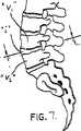
【図7】 脊柱の一部を例示する図である。
【図8】 互いに隣接する椎骨間に構成された椎間腔内部に図4の椎間用補綴具が位置決めされているのを例示する、図7の線8−8に沿って破断した図である。
【図9】 椎間板補綴の代替の実施形態の斜視図である。
【図10】 椎間板補綴の別な代替の実施形態の斜視図である。
【図11A】 椎骨本体を破断した、本開示の融合ケージの頂面図を例示するための断面図である。
【図11B】 図11Aの融合ケージの斜視図である。[0001]
〔background〕
[1. Disclosure Field)
The present invention relates generally to devices and techniques for treating various spinal disorders, in particular the natural biomechanics of a spinal motion segment after removal of a damaged or diseased disc. The present invention relates to an intervertebral prosthesis that restores both the height and shape of the intervertebral disc space while maintaining the above.
[0002]
[2. Description of prior art
The purpose of intervertebral disc replacement is to provide a prosthetic intervertebral disc that combines both stability to support high loads on the patient's vertebrae and flexibility to provide sufficient mobility and adequate spinal load distribution to the patient. It is to be. In general, four basic types of artificial discs have been developed to replace some or all of the replaced discs in an attempt to maintain this harmony, ie, the four basic types are elastomers. Intervertebral discs, ball and socket discs, mechanical spring discs, and hybrid discs. Elastomeric discs typically have an elastomeric cushion sandwiched between both rigid upper and lower endplates. Elastomeric discs are advantageous in that the elastomeric cushion functions in a manner similar to disc tissue from which mechanical motion has been removed. However, the disadvantage of this disc type is that the elastomeric cushion suffers from long-term in vivo problems caused by microcracking, which undermines the usefulness of this disc type as a replacement option. Furthermore, additional difficulties are added due to the attachment of a flexible elastomeric cushion to the rigid end plate. Specific examples of elastomeric intervertebral discs include U.S. Pat.No. 5,702,450 granted to Bisery, U.S. Pat. Has been.
[0003]
Ball and socket intervertebral discs typically incorporate two plate members having internal ball and socket portions that cooperate with each other so that each plate member can perform articulating motion during vertebra movement. To. This ball-and-socket structure is elaborate in restoring the “motion” of the spine, but inferior in restoring the natural stiffness of the disc. Dislocation and wear are yet another concern for this disc type. Examples of ball-and-socket discs are disclosed in US Pat. No. 5,507,816 to Brivant and US Pat. No. 5,258,031 to Salive et al.
[0004]
A mechanical spring intervertebral disc typically incorporates one or more coiled springs disposed between mechanical end plates. The coiled spring maintains a spaced arrangement of adjacent vertebrae, while at the same time being cumulative enough to allow normal movement of the vertebrae during spring deflection and extension in either direction. It preferably has a spring constant. Disadvantages of various mechanical spring intervertebral disc types include the attachment of coiled springs to the metal end plates and wear associated with attachment at each attachment point. Examples of mechanical spring intervertebral discs are disclosed in US Pat. No. 5,458,642 issued to Bale et al. And US Pat. No. 4,309,777 issued to Patil.
[0005]
The fourth type of artificial disc, the hybrid type, incorporates two or more principles of any of the aforementioned disc types. For example, one known hybrid disc arrangement includes a ball and socket set surrounded by an elastomeric ring. While this hybrid disc offers several advantages with respect to load carrying capacity, it generally requires a large number of individual components and is complicated. In addition, long-term in vivo problems with elastomeric cushions remain as a concern, as are wear in ball and socket arrangements.
[0006]
Another type of intervertebral disc prosthesis is disclosed in US Pat. No. 5,320,644 to Baomgartner. Referring to FIGS. 1-3, the Baomgartner 644 device is an integral disc member 1 made from a strong, elastically deformable material. In the disk member 1, slits 5 parallel to each other are arranged at right angles to the axis of the disk member. The
[0007]
However, this load path is inherently cliff-like with highly localized transmission of load through sparsely installed
[0008]
Therefore, there is a need for a prosthetic disc that easily creates and provides the proper balance of flexibility and stability with improved load distribution.
[0009]
〔Overview〕
Accordingly, the present disclosure is directed to an intervertebral disc prosthesis that is dimensioned for insertion into an intervertebral space to replace at least a portion of the intervertebral disc removed from the intervertebral space between adjacent vertebrae. The intervertebral prosthesis includes a disk member that has a longitudinal axis that extends in the height direction of the disk member and a radial axis that intersects the longitudinal axis. The disk member includes an outer wall having at least one slit. The at least one slit has a first direction component and a second direction component, and facilitates transmission of a load along the outer wall.
[0010]
The outer wall has a plurality of spiral slits, and the adjacent slits are arranged in a radial relationship with respect to the longitudinal axis so that load transmission occurs along the outer wall. These slits provide the flexibility of the outer wall consistent with the natural disc.
[0011]
The disk member may further have an inner cavity. The slit preferably extends from the outer wall surface of the outer wall to the inner wall surface of the outer wall in a conductive state with the inner cavity. Support surfaces facing each other in the first and second longitudinal directions are disposed at both ends of the intervertebral disc in the longitudinal direction. The support surface is dimensioned to engage in support with portions of the vertebrae of each vertebra. At least one of the first support surface and the second support surface is an opening extending therethrough and has an opening in conduction with the inner cavity.
[0012]
The end cap can be releasably mounted on the support surface and can be positioned at least partially within the opening of the support surface. The end cap may have an internal opening dimensioned to reduce its rigidity.
[0013]
Preferred embodiments of the present disclosure are described herein with reference to the drawings.
[0014]
Detailed Description of Preferred Embodiments
Referring now to the drawings, wherein like reference numerals identify similar or identical elements in several views, and with particular reference to FIGS. 4-6, an intervertebral prosthesis of the present disclosure is disclosed. Illustrated. The
[0015]
The
[0016]
The
[0017]
With continued reference to FIGS. 4-6, the outer wall 112 is configured with a plurality of
[0018]
The
[0019]
Although a spiral slit is illustrated, it is also anticipated that multidirectional slits other than those described above that have a lateral direction component and a longitudinal direction component may be utilized. This can be exemplified by smooth slits, piecewise smooth slits, open loop slits, and the like.
[0020]
With further reference to FIGS. 4-6,
[0021]
Each component of the
[0022]
Insertion of an artificial disc The insertion of an artificial disc will be discussed with reference to Figs. An intervertebral space i configured between adjacent vertebrae V1 and V2 is accessed using a suitable retractor instrument. Thereafter, a partial disc excision or total disc excision is performed to remove the affected part of the disc. Adjacent vertebrae V1 and V2 are distracted using a suitable spreader instrument to expose the intervertebral space. Then, the
[0023]
As previously indicated, the
[0024]
Modified Embodiment FIG. 9 illustrates amodified embodiment of the present disclosure.
[0025]
FIG. 10 illustrates another alternative embodiment of the present disclosure. The
[0026]
Fusion Cage with Spiral Slit The present disclosure also has a unique fusion cage illustrated in FIGS. 11A and 11B and generally indicated by reference numeral 500. For helical fusion cage applications, load distribution with a bone graft packed inside the cage is necessary to transform the bone graft into a solid bone arthrodesis. With current fusion cages, such as those made from titanium alloys, the cage is stiff and results in the cage being the dominant load path during the fusion process.
[0027]
The fusion cage 500 of the present disclosure is preferably composed of a titanium alloy. However, the cage has a slit configuration for reducing the hardness. That is, the
[0028]
Cage 500 has an
[0029]
Further, since the fusion cage 500 does not fill the entire intervertebral disc space, when shapes other than the kidney shape of FIGS. 11A and 11B include slit shapes for reducing the total flexibility, these shapes are used. Is also expected.
[0030]
It will be understood that various modifications may be made to the embodiments disclosed herein. Therefore, the above description should not be construed as limiting the preferred embodiment, but merely as an example thereof. Those skilled in the art will envision other modifications within the scope and spirit of the claims appended hereto.
[Brief description of the drawings]
FIG. 1 illustrates a prior art intervertebral disc prosthesis.
FIG. 2 illustrates a prior art intervertebral disc prosthesis.
FIG. 3 illustrates a prior art intervertebral disc prosthesis.
FIG. 4 is a perspective view of an artificial disc prosthesis according to the principles of the present disclosure having a disk member and an end cap mounted on the disk member.
FIG. 5 is a perspective view of the intervertebral prosthesis of FIG. 4 with the end cap removed from the disk member.
6 is a cross-sectional view of the intervertebral prosthesis of FIG. 4;
FIG. 7 is a diagram illustrating a part of the spinal column.
8 is a cutaway view taken along line 8-8 of FIG. 7 illustrating the positioning of the intervertebral prosthesis of FIG. 4 within an intervertebral space defined between adjacent vertebrae. is there.
FIG. 9 is a perspective view of an alternative embodiment of an intervertebral disc prosthesis.
FIG. 10 is a perspective view of another alternative embodiment of an intervertebral disc prosthesis.
FIG. 11A is a cross-sectional view illustrating a top view of the fusion cage of the present disclosure with the vertebral body broken away.
FIG. 11B is a perspective view of the fusion cage of FIG. 11A.
Claims (27)
Translated fromJapanese隣接した椎骨間の椎間腔から取出した椎間板の少なくとも一部を置き換えるために、椎間腔内に挿入できるように寸法決めされたディスク部材102を有し、
このディスク部材は、
その高さ方向に延びる長手方向軸線と、
この長手方向軸線を横切る半径方向軸線とを有し、
少なくとも1つのスリットを有する外壁を構成し、
この少なくとも1つのスリットは、第1方向成分と、この第1の方向成分とは異なる第2方向成分とを有し、
前記外壁が連続スリットを有し、この連続スリットは、その長手方向に配置された部分が少なくとも部分的に重なり関係をなすように、外壁の周りに配列されている、
椎間用補綴具。An intervertebral prosthesis ,
A disk member 102 sized for insertion into an intervertebral space to replace at least a portion of an intervertebral disc removed from an intervertebral space between adjacent vertebrae;
This disk member is
A longitudinal axis extending in the height direction;
A radial axis transverse to this longitudinal axis,
Constituting an outer wall having at least one slit;
The at least one slit has a first direction component and a second direction component different from the first direction component;
The outer wall has a continuous slit, and the continuous slit is arranged around the outer wall so that portions arranged in the longitudinal direction thereof are at least partially overlapped with each other.
Intervertebral prosthesis.
隣接した椎骨間の椎間腔から取出した椎間板の少なくとも一部を置き換えるために、椎間腔内に挿入できるように寸法決めされた本体部材を有し、
この本体部材は、
外壁と、
内キャビティと、
外壁の各端部に配置された支持面とを有し、
外壁は、複数の螺旋状スリットを有し、内キャビティと連通するように延び、
前記外壁が連続スリットを有し、この連続スリットは、その長手方向に配置された部分が少なくとも部分的に重なり関係をなすように、外壁の周りに配列されている、
椎間用補綴具。An intervertebral prosthesis ,
A body member dimensioned to be inserted into the intervertebral space to replace at least a portion of the disc removed from the intervertebral space between adjacent vertebrae;
This bodymember,
The outer wall,
An inner cavity,
And a support surface disposedat each end of the outer wall,
The outer wall hasa plurality of spiral slits and extends to communicate with the inner cavity;
The outer wall has a continuous slit, and the continuous slit is arranged around the outer wall so that portions arranged in the longitudinal direction thereof are at least partially overlapped with each other.
Intervertebral prosthesis.
隣接した椎骨間の椎間腔から取出した椎間板の少なくとも一部を置き換えるために、椎間腔内に挿入できるように寸法決めされたディスク部材を有し、
このディスク部材は、
長手方向軸線と、
この長手方向軸線を横切る半径方向軸線とを有し、
ディスク部材は、
多方向径路をなす複数のスリットを有する外壁部分を有し、
多方向経路の少なくとも一部分は長手方向成分を有し、
隣接したスリットは、長手方向軸線に対して半径方向関係をなして配置され、外壁内に十分延びるように寸法決めされ、それにより、椎間腔内へのディスク部材の挿入時、ディスク部材に及ぼされる力が外壁部分に沿って伝達され、
前記外壁が連続スリットを有し、この連続スリットは、その長手方向に配置された部分が少なくとも部分的に重なり関係をなすように、外壁の周りに配列されている、
椎間用補綴具。An intervertebral prosthesis ,
A disk member dimensioned to be inserted into the intervertebral space to replace at least a portion of the disc removed from the intervertebral space between adjacent vertebrae;
The discmember,
A longitudinal axis;
A radial axis transverse to this longitudinal axis,
The disk member
An outer wall portion having a plurality of slits forming a multidirectional path;
At least a portion of the multidirectional path has a longitudinal component;
Adjacent slits are placed in a radial relationship tothe longitudinal axis and are dimensioned to extend sufficiently into the outer wall so that the disk member is not affected during insertion of the disk member into the intervertebral space. Force transmitted along the outer wall,
The outer wall has a continuous slit, and the continuous slit is arranged around the outer wall so that portions arranged in the longitudinal direction thereof are at least partially overlapped with each other.
Intervertebral prosthesis.
隣接した椎骨間の椎間腔から取出した椎間板の少なくとも一部を置き換えるために、椎間腔内に挿入できるように寸法決めされたディスク部材を有し、
このディスク部材は、
隣接した椎骨を間隔を設けた関係をなして支持するのに十分な剛性と、
長手方向軸線とを有し、
ディスク部材は、少なくとも1つのスリットを有する外壁部分と、内キャビティとを有し、
前記外壁が連続スリットを有し、この連続スリットは、その長手方向に配置された部分が少なくとも部分的に重なり関係をなすように、外壁の周りに配列されている、
椎間用補綴具。An intervertebral prosthesis ,
A disk member dimensioned to be inserted into the intervertebral space to replace at least a portion of the disc removed from the intervertebral space between adjacent vertebrae;
This disk member
Sufficient rigidity to support adjacent vertebrae in a spaced relationship;
Having a longitudinal axis;
The disk member has an outer wall portion having at least one slit, and an inner cavity,
The outer wall has a continuous slit, and the continuous slit is arranged around the outer wall so that portions arranged in the longitudinal direction thereof are at least partially overlapped with each other.
Intervertebral prosthesis.
Applications Claiming Priority (3)
| Application Number | Priority Date | Filing Date | Title |
|---|---|---|---|
| US09/098,606US6296664B1 (en) | 1998-06-17 | 1998-06-17 | Artificial intervertebral disc |
| US09/098,606 | 1998-06-17 | ||
| PCT/US1999/013509WO1999065425A2 (en) | 1998-06-17 | 1999-06-16 | Artificial intervertebral disc |
Publications (2)
| Publication Number | Publication Date |
|---|---|
| JP2002518090A JP2002518090A (en) | 2002-06-25 |
| JP4122134B2true JP4122134B2 (en) | 2008-07-23 |
Family
ID=22270087
Family Applications (1)
| Application Number | Title | Priority Date | Filing Date |
|---|---|---|---|
| JP2000554307AExpired - Fee RelatedJP4122134B2 (en) | 1998-06-17 | 1999-06-16 | Artificial disc |
Country Status (6)
| Country | Link |
|---|---|
| US (3) | US6296664B1 (en) |
| EP (1) | EP1087732B1 (en) |
| JP (1) | JP4122134B2 (en) |
| AU (1) | AU5082799A (en) |
| DE (1) | DE69917634T2 (en) |
| WO (1) | WO1999065425A2 (en) |
Families Citing this family (244)
| Publication number | Priority date | Publication date | Assignee | Title |
|---|---|---|---|---|
| US6296664B1 (en)* | 1998-06-17 | 2001-10-02 | Surgical Dynamics, Inc. | Artificial intervertebral disc |
| FR2782914B1 (en)* | 1998-09-04 | 2000-12-01 | Dimso Sa | INTERSOMATIC CAGE TYPE IMPLANT, ESPECIALLY FOR CERVICAL VERTEBRES |
| US7331994B2 (en)* | 1999-05-17 | 2008-02-19 | Vanderbilt University | Intervertebral disc replacement prosthesis |
| US20050234553A1 (en)* | 1999-05-17 | 2005-10-20 | Vanderbilt University | Intervertebral disc replacement prothesis |
| US6964686B2 (en)* | 1999-05-17 | 2005-11-15 | Vanderbilt University | Intervertebral disc replacement prosthesis |
| FR2897259B1 (en) | 2006-02-15 | 2008-05-09 | Ldr Medical Soc Par Actions Si | INTERSOMATIC TRANSFORAMINAL CAGE WITH INTERBREBAL FUSION GRAFT AND CAGE IMPLANTATION INSTRUMENT |
| US6875235B2 (en)* | 1999-10-08 | 2005-04-05 | Bret A. Ferree | Prosthetic joints with contained compressible resilient members |
| DE19952939A1 (en)* | 1999-11-03 | 2001-05-10 | Tutogen Medical Gmbh | Bone material implant |
| FR2808995B1 (en) | 2000-05-18 | 2003-02-21 | Aesculap Sa | INTERSOMATIC CAGE WITH UNIFIED GRAFT |
| US6899734B2 (en)* | 2001-03-23 | 2005-05-31 | Howmedica Osteonics Corp. | Modular implant for fusing adjacent bone structure |
| DE10116412C1 (en)* | 2001-04-02 | 2003-01-16 | Ulrich Gmbh & Co Kg | Implant to be inserted between the vertebral body of the spine |
| US6719794B2 (en) | 2001-05-03 | 2004-04-13 | Synthes (U.S.A.) | Intervertebral implant for transforaminal posterior lumbar interbody fusion procedure |
| US6974480B2 (en) | 2001-05-03 | 2005-12-13 | Synthes (Usa) | Intervertebral implant for transforaminal posterior lumbar interbody fusion procedure |
| FR2824261B1 (en) | 2001-05-04 | 2004-05-28 | Ldr Medical | INTERVERTEBRAL DISC PROSTHESIS AND IMPLEMENTATION METHOD AND TOOLS |
| FR2827156B1 (en) | 2001-07-13 | 2003-11-14 | Ldr Medical | VERTEBRAL CAGE DEVICE WITH MODULAR FASTENING |
| ATE426377T1 (en) | 2001-07-16 | 2009-04-15 | Spinecore Inc | ARTIFICIAL DISC WITH A FORCE-RESTORING ELEMENT IN THE FORM OF A WAVE WASHER |
| US6468310B1 (en) | 2001-07-16 | 2002-10-22 | Third Millennium Engineering, Llc | Intervertebral spacer device having a wave washer force restoring element |
| CA2356535A1 (en)* | 2001-09-04 | 2003-03-04 | Sylvio Quesnel | Intervertebral fusion device |
| US7267687B2 (en)* | 2001-10-02 | 2007-09-11 | Rex Medical, L.P | Spinal implant and method of use |
| US6736850B2 (en)* | 2001-12-28 | 2004-05-18 | Spinal Concepts, Inc. | Vertebral pseudo arthrosis device and method |
| US6991653B2 (en)* | 2002-03-21 | 2006-01-31 | Sdgi Holdings, Inc. | Vertebral body and disc space replacement devices |
| US7066958B2 (en)* | 2002-05-10 | 2006-06-27 | Ferree Bret A | Prosthetic components with partially contained compressible resilient members |
| US7235102B2 (en)* | 2002-05-10 | 2007-06-26 | Ferree Bret A | Prosthetic components with contained compressible resilient members |
| US7291171B2 (en)* | 2002-05-10 | 2007-11-06 | Ferree Bret A | Artificial disc replacement (ADR) using elastic tether member |
| US20040024461A1 (en)* | 2002-05-10 | 2004-02-05 | Ferree Bret A. | Spring and spherical joint artificial disc replacements |
| US7001433B2 (en) | 2002-05-23 | 2006-02-21 | Pioneer Laboratories, Inc. | Artificial intervertebral disc device |
| US8388684B2 (en) | 2002-05-23 | 2013-03-05 | Pioneer Signal Technology, Inc. | Artificial disc device |
| EP1542626B1 (en) | 2002-08-15 | 2012-09-26 | Synthes GmbH | Controlled artificial intervertebral disc implant |
| CA2495404C (en) | 2002-08-15 | 2011-05-03 | Justin K. Coppes | Intervertebral disc implant |
| US7101400B2 (en)* | 2002-08-19 | 2006-09-05 | Jeffery Thramann | Shaped memory artificial disc and methods of engrafting the same |
| US20060293753A1 (en)* | 2002-08-19 | 2006-12-28 | Lanx, Llc | Corrective artificial disc |
| US7537614B2 (en) | 2002-09-18 | 2009-05-26 | Synthes Usa, Llc | Implant comprising a two-piece joint |
| AU2003286531A1 (en)* | 2002-10-21 | 2004-05-13 | 3Hbfm, Llc | Intervertebral disk prosthesis |
| US7273496B2 (en) | 2002-10-29 | 2007-09-25 | St. Francis Medical Technologies, Inc. | Artificial vertebral disk replacement implant with crossbar spacer and method |
| US7083649B2 (en) | 2002-10-29 | 2006-08-01 | St. Francis Medical Technologies, Inc. | Artificial vertebral disk replacement implant with translating pivot point |
| US7497859B2 (en) | 2002-10-29 | 2009-03-03 | Kyphon Sarl | Tools for implanting an artificial vertebral disk |
| US6966929B2 (en) | 2002-10-29 | 2005-11-22 | St. Francis Medical Technologies, Inc. | Artificial vertebral disk replacement implant with a spacer |
| US20040133278A1 (en)* | 2002-10-31 | 2004-07-08 | Marino James F. | Spinal disc implant |
| FR2846550B1 (en) | 2002-11-05 | 2006-01-13 | Ldr Medical | INTERVERTEBRAL DISC PROSTHESIS |
| US7192447B2 (en) | 2002-12-19 | 2007-03-20 | Synthes (Usa) | Intervertebral implant |
| US7500991B2 (en) | 2002-12-31 | 2009-03-10 | Depuy Acromed, Inc. | Banana cage |
| WO2004066884A1 (en) | 2003-01-31 | 2004-08-12 | Spinalmotion, Inc. | Intervertebral prosthesis placement instrument |
| ZA200506029B (en) | 2003-01-31 | 2006-10-25 | Spinalmotion Inc | Spinal Midline Indicator |
| WO2004084742A1 (en) | 2003-03-24 | 2004-10-07 | Theken Surgical Llc | Spinal implant adjustment device |
| EP1610740A4 (en) | 2003-04-04 | 2009-04-08 | Theken Disc Llc | Artificial disc prosthesis |
| BRPI0409091A (en)* | 2003-04-07 | 2006-04-11 | Cervitech Inc | intervertebral joint prosthesis for the cervical spine |
| US8012212B2 (en)* | 2003-04-07 | 2011-09-06 | Nuvasive, Inc. | Cervical intervertebral disk prosthesis |
| US7291173B2 (en) | 2003-05-06 | 2007-11-06 | Aesculap Ii, Inc. | Artificial intervertebral disc |
| US7105024B2 (en) | 2003-05-06 | 2006-09-12 | Aesculap Ii, Inc. | Artificial intervertebral disc |
| DE10324108B3 (en)* | 2003-05-21 | 2005-01-27 | Aesculap Ag & Co. Kg | Backbone implant is inserted with contracted contact disc which is expanded to optimum area following insertion |
| US20090076614A1 (en)* | 2007-09-17 | 2009-03-19 | Spinalmotion, Inc. | Intervertebral Prosthetic Disc with Shock Absorption Core |
| US7575599B2 (en) | 2004-07-30 | 2009-08-18 | Spinalmotion, Inc. | Intervertebral prosthetic disc with metallic core |
| US10052211B2 (en) | 2003-05-27 | 2018-08-21 | Simplify Medical Pty Ltd. | Prosthetic disc for intervertebral insertion |
| US7442211B2 (en) | 2003-05-27 | 2008-10-28 | Spinalmotion, Inc. | Intervertebral prosthetic disc |
| US7252685B2 (en)* | 2003-06-05 | 2007-08-07 | Sdgi Holdings, Inc. | Fusion implant and method of making same |
| US7537612B2 (en)* | 2003-06-20 | 2009-05-26 | Warsaw Orthopedic, Inc. | Lumbar composite nucleus |
| DE10330698B4 (en) | 2003-07-08 | 2005-05-25 | Aesculap Ag & Co. Kg | Intervertebral implant |
| DE20310433U1 (en) | 2003-07-08 | 2003-09-04 | Aesculap AG & Co. KG, 78532 Tuttlingen | Surgical device for inserting dual component implant into appropriate space at spine, comprising particularly shaped holding area |
| US7695515B2 (en)* | 2003-07-15 | 2010-04-13 | Spinal Generations, Llc | Spinal disc prosthesis system |
| US20050015150A1 (en)* | 2003-07-17 | 2005-01-20 | Lee Casey K. | Intervertebral disk and nucleus prosthesis |
| US7153325B2 (en)* | 2003-08-01 | 2006-12-26 | Ultra-Kinetics, Inc. | Prosthetic intervertebral disc and methods for using the same |
| US7909869B2 (en) | 2003-08-05 | 2011-03-22 | Flexuspine, Inc. | Artificial spinal unit assemblies |
| US7799082B2 (en) | 2003-08-05 | 2010-09-21 | Flexuspine, Inc. | Artificial functional spinal unit system and method for use |
| US7753958B2 (en) | 2003-08-05 | 2010-07-13 | Gordon Charles R | Expandable intervertebral implant |
| DE10339170B4 (en) | 2003-08-22 | 2009-10-15 | Aesculap Ag | Intervertebral implant |
| AU2003272683A1 (en)* | 2003-09-23 | 2005-05-11 | Vanderbilt University | Intervertebral disc replacement prosthesis |
| US7255714B2 (en) | 2003-09-30 | 2007-08-14 | Michel H. Malek | Vertically adjustable intervertebral disc prosthesis |
| DE10348329B3 (en) | 2003-10-17 | 2005-02-17 | Biedermann Motech Gmbh | Rod-shaped element used in spinal column and accident surgery for connecting two bone-anchoring elements comprises a rigid section and an elastic section that are made in one piece |
| DE102004021861A1 (en)* | 2004-05-04 | 2005-11-24 | Biedermann Motech Gmbh | Implant for temporary or permanent replacement of vertebra or intervertebral disk, comprising solid central element and outer elements with openings |
| JP2007508085A (en)* | 2003-10-17 | 2007-04-05 | ヴィーダーマン モテッヒ ゲーエムベーハー | Flexible implant |
| US6966930B2 (en)* | 2003-10-20 | 2005-11-22 | Impliant Ltd. | Facet prosthesis |
| US7520899B2 (en) | 2003-11-05 | 2009-04-21 | Kyphon Sarl | Laterally insertable artificial vertebral disk replacement implant with crossbar spacer |
| US8632570B2 (en) | 2003-11-07 | 2014-01-21 | Biedermann Technologies Gmbh & Co. Kg | Stabilization device for bones comprising a spring element and manufacturing method for said spring element |
| US7670377B2 (en) | 2003-11-21 | 2010-03-02 | Kyphon Sarl | Laterally insertable artifical vertebral disk replacement implant with curved spacer |
| US7862586B2 (en) | 2003-11-25 | 2011-01-04 | Life Spine, Inc. | Spinal stabilization systems |
| US7481839B2 (en) | 2003-12-02 | 2009-01-27 | Kyphon Sarl | Bioresorbable interspinous process implant for use with intervertebral disk remediation or replacement implants and procedures |
| US20050154462A1 (en) | 2003-12-02 | 2005-07-14 | St. Francis Medical Technologies, Inc. | Laterally insertable artificial vertebral disk replacement implant with translating pivot point |
| WO2005055871A2 (en)* | 2003-12-03 | 2005-06-23 | Nebojsa Kovacevic | Prosthetic shock absorber |
| US7588600B2 (en)* | 2003-12-10 | 2009-09-15 | Axiomed Spine Corporation | Method for replacing a damaged spinal disc |
| EP2113227B1 (en) | 2004-02-04 | 2015-07-29 | LDR Medical | Intervertebral disc prosthesis |
| FR2865629B1 (en) | 2004-02-04 | 2007-01-26 | Ldr Medical | INTERVERTEBRAL DISC PROSTHESIS |
| FR2869528B1 (en) | 2004-04-28 | 2007-02-02 | Ldr Medical | INTERVERTEBRAL DISC PROSTHESIS |
| US7544208B1 (en) | 2004-05-03 | 2009-06-09 | Theken Spine, Llc | Adjustable corpectomy apparatus |
| KR101276414B1 (en) | 2004-05-04 | 2013-06-19 | 비이더만 테크놀로지스 게엠베하 & 코. 카게 | Flexible space holder |
| US7833271B2 (en)* | 2004-05-04 | 2010-11-16 | Zimmer Spine, Inc. | Spinal implants with body and insert |
| EP1949872B1 (en)* | 2004-05-04 | 2016-12-28 | Biedermann Technologies GmbH & Co. KG | Flexible spacer |
| US7297162B2 (en)* | 2004-06-09 | 2007-11-20 | Zimmer Spine, Inc. | Expandable helical cage |
| DE202004009542U1 (en) | 2004-06-16 | 2004-08-12 | Aesculap Ag & Co. Kg | Artificial intervertebral disk, comprising core with intensely curved upper and less curved lower surface |
| US7585326B2 (en) | 2004-08-06 | 2009-09-08 | Spinalmotion, Inc. | Methods and apparatus for intervertebral disc prosthesis insertion |
| US7799081B2 (en) | 2004-09-14 | 2010-09-21 | Aeolin, Llc | System and method for spinal fusion |
| US7763024B2 (en)* | 2004-09-23 | 2010-07-27 | Spine Solutions, Inc. | Adjustable cutting of cutout in vertebral bone |
| US7780731B2 (en)* | 2004-11-26 | 2010-08-24 | Spine Solutions, Inc. | Intervertebral implant |
| US7481840B2 (en) | 2004-09-29 | 2009-01-27 | Kyphon Sarl | Multi-piece artificial spinal disk replacement device with selectably positioning articulating element |
| US7575600B2 (en) | 2004-09-29 | 2009-08-18 | Kyphon Sarl | Artificial vertebral disk replacement implant with translating articulation contact surface and method |
| WO2006058221A2 (en) | 2004-11-24 | 2006-06-01 | Abdou Samy M | Devices and methods for inter-vertebral orthopedic device placement |
| FR2879436B1 (en) | 2004-12-22 | 2007-03-09 | Ldr Medical | INTERVERTEBRAL DISC PROSTHESIS |
| US7309357B2 (en)* | 2004-12-30 | 2007-12-18 | Infinesse, Corporation | Prosthetic spinal discs |
| WO2006078663A2 (en)* | 2005-01-19 | 2006-07-27 | Nexgen Spine, Inc. | Elastomeric intervertebral disc prosthesis |
| AU2006206559A1 (en)* | 2005-01-19 | 2006-07-27 | Nexgen Spine, Inc. | Fixation of elastomer to rigid structures |
| US8083797B2 (en) | 2005-02-04 | 2011-12-27 | Spinalmotion, Inc. | Intervertebral prosthetic disc with shock absorption |
| US7578848B2 (en)* | 2005-03-03 | 2009-08-25 | Cervical Xpand, Llc | Intervertebral stabilizer |
| US7632312B2 (en)* | 2005-03-24 | 2009-12-15 | Neurocare International, Inc. | Artifical lumbar disc |
| US8986383B2 (en)* | 2005-03-24 | 2015-03-24 | Igip, Llc | End cap and connector for a spinal implant |
| US7361192B2 (en)* | 2005-04-22 | 2008-04-22 | Doty Keith L | Spinal disc prosthesis and methods of use |
| US7799080B2 (en)* | 2005-04-22 | 2010-09-21 | Doty Keith L | Spinal disc prosthesis and methods of use |
| US20120312779A1 (en) | 2005-05-06 | 2012-12-13 | Titian Spine, LLC | Methods for manufacturing implants having integration surfaces |
| US8403991B2 (en) | 2005-05-06 | 2013-03-26 | Titan Spine Llc | Implant with critical ratio of load bearing surface area to central opening area |
| US8585765B2 (en) | 2005-05-06 | 2013-11-19 | Titan Spine, Llc | Endplate-preserving spinal implant having a raised expulsion-resistant edge |
| US8758442B2 (en) | 2005-05-06 | 2014-06-24 | Titan Spine, Llc | Composite implants having integration surfaces composed of a regular repeating pattern |
| US8562685B2 (en) | 2005-05-06 | 2013-10-22 | Titan Spine, Llc | Spinal implant and integration plate for optimizing vertebral endplate contact load-bearing edges |
| US9168147B2 (en) | 2005-05-06 | 2015-10-27 | Titan Spine, Llc | Self-deploying locking screw retention device |
| US8585766B2 (en) | 2005-05-06 | 2013-11-19 | Titan Spine, Llc | Endplate-preserving spinal implant with an integration plate having durable connectors |
| US8758443B2 (en) | 2005-05-06 | 2014-06-24 | Titan Spine, Llc | Implants with integration surfaces having regular repeating surface patterns |
| US8551176B2 (en) | 2005-05-06 | 2013-10-08 | Titan Spine, Llc | Spinal implant having a passage for enhancing contact between bone graft material and cortical endplate bone |
| US11096796B2 (en) | 2005-05-06 | 2021-08-24 | Titan Spine, Llc | Interbody spinal implant having a roughened surface topography on one or more internal surfaces |
| US8562684B2 (en) | 2005-05-06 | 2013-10-22 | Titan Spine, Llc | Endplate-preserving spinal implant with an integration plate having a roughened surface topography |
| US8545568B2 (en) | 2005-05-06 | 2013-10-01 | Titan Spine, Llc | Method of using instruments and interbody spinal implants to enhance distraction |
| US8585767B2 (en) | 2005-05-06 | 2013-11-19 | Titan Spine, Llc | Endplate-preserving spinal implant with an integration plate having durable connectors |
| US8591590B2 (en) | 2005-05-06 | 2013-11-26 | Titan Spine, Llc | Spinal implant having a transverse aperture |
| US8480749B2 (en) | 2005-05-06 | 2013-07-09 | Titan Spine, Llc | Friction fit and vertebral endplate-preserving spinal implant |
| US8617248B2 (en) | 2005-05-06 | 2013-12-31 | Titan Spine, Llc | Spinal implant having variable ratios of the integration surface area to the axial passage area |
| US9125756B2 (en) | 2005-05-06 | 2015-09-08 | Titan Spine, Llc | Processes for producing regular repeating patterns on surfaces of interbody devices |
| US8435302B2 (en) | 2005-05-06 | 2013-05-07 | Titan Spine, Llc | Instruments and interbody spinal implants enhancing disc space distraction |
| US8992622B2 (en) | 2005-05-06 | 2015-03-31 | Titan Spine, Llc | Interbody spinal implant having a roughened surface topography |
| US8262737B2 (en) | 2005-05-06 | 2012-09-11 | Titan Spine, Llc | Composite interbody spinal implant having openings of predetermined size and shape |
| US8814939B2 (en) | 2005-05-06 | 2014-08-26 | Titan Spine, Llc | Implants having three distinct surfaces |
| FR2887762B1 (en) | 2005-06-29 | 2007-10-12 | Ldr Medical Soc Par Actions Si | INTERVERTEBRAL DISC PROSTHESIS INSERTION INSTRUMENTATION BETWEEN VERTEBRATES |
| US20070016301A1 (en)* | 2005-07-14 | 2007-01-18 | Medical Device Concepts Llc. | Multi-axial interbody spacer device |
| US8328851B2 (en) | 2005-07-28 | 2012-12-11 | Nuvasive, Inc. | Total disc replacement system and related methods |
| DE602005007223D1 (en) | 2005-08-24 | 2008-07-10 | Biedermann Motech Gmbh | Rod-shaped element for use in spine or trauma surgery and stabilization device with such an element |
| US7731753B2 (en)* | 2005-09-01 | 2010-06-08 | Spinal Kinetics, Inc. | Prosthetic intervertebral discs |
| US20070050032A1 (en)* | 2005-09-01 | 2007-03-01 | Spinal Kinetics, Inc. | Prosthetic intervertebral discs |
| FR2891135B1 (en) | 2005-09-23 | 2008-09-12 | Ldr Medical Sarl | INTERVERTEBRAL DISC PROSTHESIS |
| US20070083200A1 (en)* | 2005-09-23 | 2007-04-12 | Gittings Darin C | Spinal stabilization systems and methods |
| US20070088439A1 (en)* | 2005-10-13 | 2007-04-19 | Jeffery Thramann | Artificial disc with endplates having cages to promote bone fusion |
| EP1948041A2 (en)* | 2005-10-24 | 2008-07-30 | Nexgen Spine, Inc. | Intervertebral disc replacement and associated instrumentation |
| FR2893838B1 (en) | 2005-11-30 | 2008-08-08 | Ldr Medical Soc Par Actions Si | PROSTHESIS OF INTERVERTEBRAL DISC AND INSTRUMENTATION OF INSERTION OF THE PROSTHESIS BETWEEN VERTEBRATES |
| US7618454B2 (en)* | 2005-12-07 | 2009-11-17 | Zimmer Spine, Inc. | Transforaminal lumbar interbody fusion spacers |
| NZ568985A (en)* | 2005-12-08 | 2010-11-26 | Fbcdevice Aps | Disc implant |
| WO2007075411A2 (en)* | 2005-12-16 | 2007-07-05 | Thomas Haider Patents, A Limited Liability Company | An intervertebral prosthesis for supporting adjacent vertebral bodies enabling the creation of soft fusion and method |
| US8118869B2 (en) | 2006-03-08 | 2012-02-21 | Flexuspine, Inc. | Dynamic interbody device |
| WO2007121320A2 (en) | 2006-04-12 | 2007-10-25 | Spinalmotion, Inc. | Posterior spinal device and method |
| US20070255414A1 (en)* | 2006-05-01 | 2007-11-01 | Sdgi Holdings, Inc. | Intervertebral implants with one or more covers and methods of use |
| US8715350B2 (en) | 2006-09-15 | 2014-05-06 | Pioneer Surgical Technology, Inc. | Systems and methods for securing an implant in intervertebral space |
| WO2008034135A2 (en) | 2006-09-15 | 2008-03-20 | Pioneer Surgical Technology, Inc. | Joint arthroplasty devices having articulating members |
| WO2008039850A2 (en)* | 2006-09-26 | 2008-04-03 | Nexgen Spine, Inc. | Intervertebral. prosthesis endplate having double dome and surgical tools for preparing the vertebral body endplate to receive the prosthesis |
| US9278007B2 (en) | 2006-09-26 | 2016-03-08 | Spinal Kinetics, Inc. | Prosthetic intervertebral discs having cast end plates and methods for making and using them |
| US8403987B2 (en) | 2006-09-27 | 2013-03-26 | Spinal Kinetics Inc. | Prosthetic intervertebral discs having compressible core elements bounded by fiber-containing membranes |
| US9381098B2 (en)* | 2006-09-28 | 2016-07-05 | Spinal Kinetics, Inc. | Tool systems for implanting prosthetic intervertebral discs |
| US8092533B2 (en)* | 2006-10-03 | 2012-01-10 | Warsaw Orthopedic, Inc. | Dynamic devices and methods for stabilizing vertebral members |
| US8066750B2 (en) | 2006-10-06 | 2011-11-29 | Warsaw Orthopedic, Inc | Port structures for non-rigid bone plates |
| CA2668655A1 (en) | 2006-11-16 | 2008-05-29 | Rex Medical, L.P. | Spinal implant and method of use |
| US8029569B2 (en) | 2006-11-20 | 2011-10-04 | International Spinal Innovations, Llc | Implantable spinal disk |
| US7905922B2 (en) | 2006-12-20 | 2011-03-15 | Zimmer Spine, Inc. | Surgical implant suitable for replacement of an intervertebral disc |
| US20080177389A1 (en)* | 2006-12-21 | 2008-07-24 | Rob Gene Parrish | Intervertebral disc spacer |
| US7959677B2 (en) | 2007-01-19 | 2011-06-14 | Flexuspine, Inc. | Artificial functional spinal unit system and method for use |
| US8465546B2 (en) | 2007-02-16 | 2013-06-18 | Ldr Medical | Intervertebral disc prosthesis insertion assemblies |
| BRPI0808018A2 (en)* | 2007-03-07 | 2014-06-17 | Ulrich Gmbh & Co Kg | INTERVERTEBRAL IMPLANT WITH AN ELASTIC COMPONENT |
| FR2916956B1 (en) | 2007-06-08 | 2012-12-14 | Ldr Medical | INTERSOMATIC CAGE, INTERVERTEBRAL PROSTHESIS, ANCHORING DEVICE AND IMPLANTATION INSTRUMENTATION |
| US8298287B2 (en)* | 2007-06-26 | 2012-10-30 | Depuy Spine, Inc. | Intervertebral motion disc with helical shock absorber |
| US7922767B2 (en) | 2007-07-07 | 2011-04-12 | Jmea Corporation | Disk fusion implant |
| EP2018832B1 (en)* | 2007-07-26 | 2011-09-21 | BIEDERMANN MOTECH GmbH | Intervertebral disc prosthesis |
| US8052728B2 (en)* | 2007-07-31 | 2011-11-08 | Zimmer Spine, Inc. | Method for stabilizing a facet joint |
| US7803192B2 (en) | 2007-07-31 | 2010-09-28 | Custom Spine, Inc. | Artificial intervertebral disc |
| US20090043391A1 (en) | 2007-08-09 | 2009-02-12 | Spinalmotion, Inc. | Customized Intervertebral Prosthetic Disc with Shock Absorption |
| US8182514B2 (en) | 2007-10-22 | 2012-05-22 | Flexuspine, Inc. | Dampener system for a posterior stabilization system with a fixed length elongated member |
| US8523912B2 (en) | 2007-10-22 | 2013-09-03 | Flexuspine, Inc. | Posterior stabilization systems with shared, dual dampener systems |
| US8187330B2 (en)* | 2007-10-22 | 2012-05-29 | Flexuspine, Inc. | Dampener system for a posterior stabilization system with a variable length elongated member |
| US8157844B2 (en) | 2007-10-22 | 2012-04-17 | Flexuspine, Inc. | Dampener system for a posterior stabilization system with a variable length elongated member |
| US20090105834A1 (en)* | 2007-10-22 | 2009-04-23 | Spinalmotion, Inc. | Dynamic Spacer Device and Method for Spanning a Space Formed upon Removal of an Intervertebral Disc |
| US8267965B2 (en) | 2007-10-22 | 2012-09-18 | Flexuspine, Inc. | Spinal stabilization systems with dynamic interbody devices |
| US8162994B2 (en) | 2007-10-22 | 2012-04-24 | Flexuspine, Inc. | Posterior stabilization system with isolated, dual dampener systems |
| US20090157185A1 (en)* | 2007-12-18 | 2009-06-18 | Chong Chol Kim | Prosthetic Monolithic Spinal Discs and Method of Customizing and Constructing Discs |
| US8617214B2 (en) | 2008-01-07 | 2013-12-31 | Mmsn Limited Partnership | Spinal tension band |
| US7935133B2 (en) | 2008-02-08 | 2011-05-03 | Mmsn Limited Partnership | Interlaminar hook |
| US8764833B2 (en) | 2008-03-11 | 2014-07-01 | Spinalmotion, Inc. | Artificial intervertebral disc with lower height |
| US20110029087A1 (en)* | 2008-04-04 | 2011-02-03 | Haider Thomas T | Intervertebral prostheses with compliant filler material for supporting adjacent vertebral bodies and method |
| US9034038B2 (en) | 2008-04-11 | 2015-05-19 | Spinalmotion, Inc. | Motion limiting insert for an artificial intervertebral disc |
| EP2278941A1 (en) | 2008-05-05 | 2011-02-02 | Spinalmotion Inc. | Polyaryletherketone artificial intervertebral disc |
| US8470045B2 (en) | 2008-05-05 | 2013-06-25 | K2M, Inc. | Endplate for an intervertebral prosthesis and prosthesis incorporating the same |
| US20090292363A1 (en)* | 2008-05-23 | 2009-11-26 | Vanderbilt University | Intervertebral prosthesis |
| US9220603B2 (en) | 2008-07-02 | 2015-12-29 | Simplify Medical, Inc. | Limited motion prosthetic intervertebral disc |
| EP2299944A4 (en) | 2008-07-17 | 2013-07-31 | Spinalmotion Inc | SYSTEM FOR INSTALLING ARTIFICIAL INTERVERTEBRAL DISCS |
| EP2299941A1 (en) | 2008-07-18 | 2011-03-30 | Spinalmotion Inc. | Posterior prosthetic intervertebral disc |
| US9700431B2 (en) | 2008-08-13 | 2017-07-11 | Smed-Ta/Td, Llc | Orthopaedic implant with porous structural member |
| US10842645B2 (en) | 2008-08-13 | 2020-11-24 | Smed-Ta/Td, Llc | Orthopaedic implant with porous structural member |
| US20100042213A1 (en) | 2008-08-13 | 2010-02-18 | Nebosky Paul S | Drug delivery implants |
| US9616205B2 (en) | 2008-08-13 | 2017-04-11 | Smed-Ta/Td, Llc | Drug delivery implants |
| JP2012500058A (en)* | 2008-08-13 | 2012-01-05 | スメド−ティーエイ/ティーディー・エルエルシー | Orthopedic implant with a porous structural member |
| US20100087923A1 (en)* | 2008-08-23 | 2010-04-08 | Abdou M Samy | Implants for facet joint repair and methods use |
| WO2010025386A1 (en) | 2008-08-29 | 2010-03-04 | Smed-Ta/Td, Llc | Orthopaedic implant |
| US7927375B2 (en) | 2008-09-12 | 2011-04-19 | Doty Keith L | Dynamic six-degrees-of-freedom intervertebral spinal disc prosthesis |
| US8187304B2 (en) | 2008-11-10 | 2012-05-29 | Malek Michel H | Facet fusion system |
| US9492214B2 (en)* | 2008-12-18 | 2016-11-15 | Michel H. Malek | Flexible spinal stabilization system |
| US20100161058A1 (en)* | 2008-12-24 | 2010-06-24 | Custom Spine, Inc. | Multiple-State Geometry Artificial Disc With Compliant Insert and Method |
| US9220547B2 (en) | 2009-03-27 | 2015-12-29 | Spinal Elements, Inc. | Flanged interbody fusion device |
| US8226724B2 (en) | 2009-06-18 | 2012-07-24 | Doty Keith L | Intervertebral spinal disc prosthesis |
| CN105326585B (en) | 2009-09-17 | 2018-12-11 | Ldr控股公司 | Intervertebral implant with extensible bone anchoring element |
| US8764806B2 (en) | 2009-12-07 | 2014-07-01 | Samy Abdou | Devices and methods for minimally invasive spinal stabilization and instrumentation |
| WO2011080535A1 (en) | 2009-12-31 | 2011-07-07 | Lrd Medical | Anchoring device, intervertebral implant and implantation instrument |
| EP2547292B1 (en)* | 2010-03-16 | 2019-04-24 | Pinnacle Spine Group, LLC | Ntervertebral implants and graft delivery systems |
| US9402734B2 (en) | 2010-07-30 | 2016-08-02 | Igip, Llc | Spacer for spinal implant |
| US9301787B2 (en) | 2010-09-27 | 2016-04-05 | Mmsn Limited Partnership | Medical apparatus and method for spinal surgery |
| US8353964B2 (en) | 2010-11-04 | 2013-01-15 | Carpenter Clyde T | Anatomic total disc replacement |
| US8388687B2 (en) | 2011-03-25 | 2013-03-05 | Flexuspine, Inc. | Interbody device insertion systems and methods |
| US8277505B1 (en) | 2011-06-10 | 2012-10-02 | Doty Keith L | Devices for providing up to six-degrees of motion having kinematically-linked components and methods of use |
| US9398960B2 (en) | 2011-09-16 | 2016-07-26 | Globus Medical, Inc. | Multi-piece intervertebral implants |
| US9204975B2 (en) | 2011-09-16 | 2015-12-08 | Globus Medical, Inc. | Multi-piece intervertebral implants |
| US8961606B2 (en)* | 2011-09-16 | 2015-02-24 | Globus Medical, Inc. | Multi-piece intervertebral implants |
| US9539109B2 (en) | 2011-09-16 | 2017-01-10 | Globus Medical, Inc. | Low profile plate |
| US8845728B1 (en) | 2011-09-23 | 2014-09-30 | Samy Abdou | Spinal fixation devices and methods of use |
| US8992619B2 (en) | 2011-11-01 | 2015-03-31 | Titan Spine, Llc | Microstructured implant surfaces |
| US9380932B1 (en) | 2011-11-02 | 2016-07-05 | Pinnacle Spine Group, Llc | Retractor devices for minimally invasive access to the spine |
| US9526627B2 (en) | 2011-11-17 | 2016-12-27 | Exactech, Inc. | Expandable interbody device system and method |
| US8287598B1 (en) | 2011-12-05 | 2012-10-16 | TrueMotion Spine, Inc. | True spinal motion preserving, shock absorbing, intervertebral spinal disc prosthesis |
| US9198769B2 (en) | 2011-12-23 | 2015-12-01 | Pioneer Surgical Technology, Inc. | Bone anchor assembly, bone plate system, and method |
| US20130226240A1 (en) | 2012-02-22 | 2013-08-29 | Samy Abdou | Spinous process fixation devices and methods of use |
| FR2987256B1 (en) | 2012-02-24 | 2014-08-08 | Ldr Medical | ANCHORING DEVICE FOR INTERVERTEBRAL IMPLANT, INTERVERTEBRAL IMPLANT AND IMPLANTATION INSTRUMENTATION |
| CA2880825C (en) | 2012-03-20 | 2021-03-16 | Titan Spine, Llc | Friction-fit spinal endplate and endplate-preserving method |
| US9198767B2 (en) | 2012-08-28 | 2015-12-01 | Samy Abdou | Devices and methods for spinal stabilization and instrumentation |
| EP2716261A1 (en) | 2012-10-02 | 2014-04-09 | Titan Spine, LLC | Implants with self-deploying anchors |
| US9498349B2 (en) | 2012-10-09 | 2016-11-22 | Titan Spine, Llc | Expandable spinal implant with expansion wedge and anchor |
| US9320617B2 (en) | 2012-10-22 | 2016-04-26 | Cogent Spine, LLC | Devices and methods for spinal stabilization and instrumentation |
| US9492288B2 (en) | 2013-02-20 | 2016-11-15 | Flexuspine, Inc. | Expandable fusion device for positioning between adjacent vertebral bodies |
| WO2014159739A1 (en) | 2013-03-14 | 2014-10-02 | Pinnacle Spine Group, Llc | Interbody implants and graft delivery systems |
| WO2014145766A1 (en)* | 2013-03-15 | 2014-09-18 | Paradigm Spine, Llc | Modular, customizable spine stabilization system |
| US9427325B2 (en)* | 2013-07-26 | 2016-08-30 | Warsaw Orthopedic, Inc. | Interbody implant and method |
| US9615935B2 (en) | 2014-01-30 | 2017-04-11 | Titan Spine, Llc | Thermally activated shape memory spring assemblies for implant expansion |
| US9517144B2 (en) | 2014-04-24 | 2016-12-13 | Exactech, Inc. | Limited profile intervertebral implant with incorporated fastening mechanism |
| KR101444638B1 (en) | 2014-04-24 | 2014-09-26 | 김현성 | Percutaneous intervertebral artificial disc replacement for minimal invasive surgery |
| US10398565B2 (en) | 2014-04-24 | 2019-09-03 | Choice Spine, Llc | Limited profile intervertebral implant with incorporated fastening and locking mechanism |
| US9901457B2 (en) | 2014-10-16 | 2018-02-27 | Jmea Corporation | Coiling implantable prostheses |
| US10857003B1 (en) | 2015-10-14 | 2020-12-08 | Samy Abdou | Devices and methods for vertebral stabilization |
| EP3386444B1 (en)* | 2015-12-07 | 2020-11-18 | Nexus Spine, L.L.C. | Porous interbody spacer |
| EP3195833B1 (en) | 2016-01-19 | 2022-01-12 | K2M, Inc. | Surgical instrument |
| US10973648B1 (en) | 2016-10-25 | 2021-04-13 | Samy Abdou | Devices and methods for vertebral bone realignment |
| US10744000B1 (en) | 2016-10-25 | 2020-08-18 | Samy Abdou | Devices and methods for vertebral bone realignment |
| WO2019051260A1 (en) | 2017-09-08 | 2019-03-14 | Pioneer Surgical Technology, Inc. | Intervertebral implants, instruments, and methods |
| USD907771S1 (en) | 2017-10-09 | 2021-01-12 | Pioneer Surgical Technology, Inc. | Intervertebral implant |
| US10893951B2 (en)* | 2018-08-07 | 2021-01-19 | Minimally Invasive Spinal Technology, LLC | Device and method for correcting spinal deformities in patients |
| AU2019342137A1 (en) | 2018-09-20 | 2021-03-25 | Spinal Elements, Inc. | Spinal implant device |
| US11179248B2 (en) | 2018-10-02 | 2021-11-23 | Samy Abdou | Devices and methods for spinal implantation |
| US11911284B2 (en) | 2020-11-19 | 2024-02-27 | Spinal Elements, Inc. | Curved expandable interbody devices and deployment tools |
| WO2022133456A1 (en) | 2020-12-17 | 2022-06-23 | Spinal Elements, Inc. | Spinal implant device |
Family Cites Families (49)
| Publication number | Priority date | Publication date | Assignee | Title |
|---|---|---|---|---|
| SE391122B (en) | 1971-01-25 | 1977-02-07 | Cutter Lab | PROTESTS IN THE FORM OF A SPINE BONIC DISC AND PROCEDURES FOR MANUFACTURE THEREOF |
| CA1146301A (en) | 1980-06-13 | 1983-05-17 | J. David Kuntz | Intervertebral disc prosthesis |
| US4309777A (en) | 1980-11-13 | 1982-01-12 | Patil Arun A | Artificial intervertebral disc |
| DE3620549A1 (en) | 1986-06-19 | 1987-12-23 | S & G Implants Gmbh | IMPLANT FOR FIXING NEXT SPINE BONES OF THE SPINE |
| CA1283501C (en) | 1987-02-12 | 1991-04-30 | Thomas P. Hedman | Artificial spinal disc |
| US4714469A (en) | 1987-02-26 | 1987-12-22 | Pfizer Hospital Products Group, Inc. | Spinal implant |
| US4863477A (en) | 1987-05-12 | 1989-09-05 | Monson Gary L | Synthetic intervertebral disc prosthesis |
| US5108438A (en) | 1989-03-02 | 1992-04-28 | Regen Corporation | Prosthetic intervertebral disc |
| US4874389A (en) | 1987-12-07 | 1989-10-17 | Downey Ernest L | Replacement disc |
| US5147404A (en) | 1987-12-07 | 1992-09-15 | Downey Ernest L | Vertebra prosthesis |
| DE3809793A1 (en) | 1988-03-23 | 1989-10-05 | Link Waldemar Gmbh Co | SURGICAL INSTRUMENT SET |
| DE8807485U1 (en) | 1988-06-06 | 1989-08-10 | Mecron Medizinische Produkte Gmbh, 1000 Berlin | Intervertebral disc endoprosthesis |
| US4911718A (en)* | 1988-06-10 | 1990-03-27 | University Of Medicine & Dentistry Of N.J. | Functional and biocompatible intervertebral disc spacer |
| AU624627B2 (en) | 1988-08-18 | 1992-06-18 | Johnson & Johnson Orthopaedics, Inc. | Functional and biocompatible intervertebral disc spacer containing elastomeric material of varying hardness |
| US5458638A (en) | 1989-07-06 | 1995-10-17 | Spine-Tech, Inc. | Non-threaded spinal implant |
| US4932975A (en) | 1989-10-16 | 1990-06-12 | Vanderbilt University | Vertebral prosthesis |
| DE8912648U1 (en) | 1989-10-23 | 1990-11-22 | Mecron Medizinische Produkte Gmbh, 1000 Berlin | Vertebral body implant |
| DE59100448D1 (en) | 1990-04-20 | 1993-11-11 | Sulzer Ag | Implant, in particular intervertebral prosthesis. |
| RU2004218C1 (en) | 1991-02-15 | 1993-12-15 | Научно-практический центр имплантатов с пам тью формы "Доктор" | Apparatus for spondylosyndesis |
| US5123926A (en) | 1991-02-22 | 1992-06-23 | Madhavan Pisharodi | Artificial spinal prosthesis |
| US5171278A (en) | 1991-02-22 | 1992-12-15 | Madhavan Pisharodi | Middle expandable intervertebral disk implants |
| US5192327A (en) | 1991-03-22 | 1993-03-09 | Brantigan John W | Surgical prosthetic implant for vertebrae |
| DE4109941A1 (en) | 1991-03-26 | 1992-10-01 | Reljica Kostic Zlatko Dr | Flexible prosthesis for backbone - comprises flexible spring forming supporting element connected to two fixing elements attached to adjacent vertebrae |
| JP3007903B2 (en) | 1991-03-29 | 2000-02-14 | 京セラ株式会社 | Artificial disc |
| DE4128332A1 (en) | 1991-08-27 | 1993-03-04 | Man Ceramics Gmbh | SPINE BONE REPLACEMENT |
| US5320644A (en) | 1991-08-30 | 1994-06-14 | Sulzer Brothers Limited | Intervertebral disk prosthesis |
| US5263953A (en)* | 1991-12-31 | 1993-11-23 | Spine-Tech, Inc. | Apparatus and system for fusing bone joints |
| US5258031A (en) | 1992-01-06 | 1993-11-02 | Danek Medical | Intervertebral disk arthroplasty |
| US5306309A (en) | 1992-05-04 | 1994-04-26 | Calcitek, Inc. | Spinal disk implant and implantation kit |
| DE4220218C2 (en) | 1992-06-20 | 1994-09-22 | S & G Implants Gmbh | Implant with an open-cell or open-pore metal structure |
| JPH06132873A (en) | 1992-10-21 | 1994-05-13 | Nec Corp | Power controller |
| US5534028A (en) | 1993-04-20 | 1996-07-09 | Howmedica, Inc. | Hydrogel intervertebral disc nucleus with diminished lateral bulging |
| FR2707480B1 (en) | 1993-06-28 | 1995-10-20 | Bisserie Michel | Intervertebral disc prosthesis. |
| US5423817A (en) | 1993-07-29 | 1995-06-13 | Lin; Chih-I | Intervertebral fusing device |
| US5423816A (en) | 1993-07-29 | 1995-06-13 | Lin; Chih I. | Intervertebral locking device |
| FR2709949B1 (en)* | 1993-09-14 | 1995-10-13 | Commissariat Energie Atomique | Intervertebral disc prosthesis. |
| US5514180A (en) | 1994-01-14 | 1996-05-07 | Heggeness; Michael H. | Prosthetic intervertebral devices |
| US5458642A (en) | 1994-01-18 | 1995-10-17 | Beer; John C. | Synthetic intervertebral disc |
| CA2135534C (en) | 1994-11-10 | 2002-03-05 | John Cairns | Tape splicing device |
| US6344057B1 (en)* | 1994-11-22 | 2002-02-05 | Sdgi Holdings, Inc. | Adjustable vertebral body replacement |
| FR2728159B1 (en) | 1994-12-16 | 1997-06-27 | Tornier Sa | ELASTIC DISC PROSTHESIS |
| US5782919A (en)* | 1995-03-27 | 1998-07-21 | Sdgi Holdings, Inc. | Interbody fusion device and method for restoration of normal spinal anatomy |
| US5702449A (en) | 1995-06-07 | 1997-12-30 | Danek Medical, Inc. | Reinforced porous spinal implants |
| KR100415064B1 (en) | 1995-10-20 | 2005-04-06 | 신테스 아게 츄어 | Intervertebral implant |
| DE19541114A1 (en) | 1995-10-26 | 1997-04-30 | Artos Med Produkte | Intervertebral implant |
| US5766253A (en) | 1996-01-16 | 1998-06-16 | Surgical Dynamics, Inc. | Spinal fusion device |
| US5824094A (en)* | 1997-10-17 | 1998-10-20 | Acromed Corporation | Spinal disc |
| US6086613A (en)* | 1997-12-23 | 2000-07-11 | Depuy Acromed, Inc. | Spacer assembly for use in spinal surgeries |
| US6296664B1 (en)* | 1998-06-17 | 2001-10-02 | Surgical Dynamics, Inc. | Artificial intervertebral disc |
- 1998
- 1998-06-17USUS09/098,606patent/US6296664B1/ennot_activeExpired - Lifetime
- 1999
- 1999-06-16WOPCT/US1999/013509patent/WO1999065425A2/enactiveIP Right Grant
- 1999-06-16DEDE69917634Tpatent/DE69917634T2/ennot_activeExpired - Lifetime
- 1999-06-16EPEP99935323Apatent/EP1087732B1/ennot_activeExpired - Lifetime
- 1999-06-16AUAU50827/99Apatent/AU5082799A/ennot_activeAbandoned
- 1999-06-16JPJP2000554307Apatent/JP4122134B2/ennot_activeExpired - Fee Related
- 2001
- 2001-08-03USUS09/921,876patent/US6656224B2/ennot_activeExpired - Fee Related
- 2003
- 2003-09-26USUS10/672,327patent/US7128762B2/ennot_activeExpired - Fee Related
Also Published As
| Publication number | Publication date |
|---|---|
| US7128762B2 (en) | 2006-10-31 |
| JP2002518090A (en) | 2002-06-25 |
| AU5082799A (en) | 2000-01-05 |
| US6656224B2 (en) | 2003-12-02 |
| EP1087732A2 (en) | 2001-04-04 |
| DE69917634T2 (en) | 2005-02-24 |
| US20040176842A1 (en) | 2004-09-09 |
| WO1999065425A2 (en) | 1999-12-23 |
| US6296664B1 (en) | 2001-10-02 |
| WO1999065425A3 (en) | 2000-02-10 |
| US20010051829A1 (en) | 2001-12-13 |
| EP1087732B1 (en) | 2004-05-26 |
| DE69917634D1 (en) | 2004-07-01 |
Similar Documents
| Publication | Publication Date | Title |
|---|---|---|
| JP4122134B2 (en) | Artificial disc | |
| US6136031A (en) | Artificial intervertebral disc | |
| US7122055B2 (en) | Artificial intervertebral disc having a spider spring force restoring element | |
| US8753399B2 (en) | Dynamic interbody device | |
| US7147665B1 (en) | Threaded cylindrical multidiscoid single or multiple array disc prosthesis | |
| US7604664B2 (en) | Spinal baseplates with ball joint coupling and a retaining member | |
| US6758861B2 (en) | Intervertebral spacer device having a wave washer force restoring element | |
| US7563285B2 (en) | Artificial intervertebral disc utilizing a ball joint coupling | |
| US7867279B2 (en) | Intervertebral disc prosthesis | |
| US6669730B2 (en) | Intervertebral spacer device utilizing a spirally slotted belleville washer having radially extending grooves | |
| US20020111686A1 (en) | Intervertebral spacer device utilizing a spirally slotted belleville washer and a rotational mounting | |
| US20060293752A1 (en) | Intervertebral disc prosthesis and associated methods | |
| US20030069642A1 (en) | Artificial intervertebral disc having a flexible wire mesh vertebral body contact element | |
| US9060871B2 (en) | Total disc replacement device | |
| US20090177283A9 (en) | Intervertebral spacer device utilizing a spirally slotted belleville washer and a rotational mounting | |
| US20020111687A1 (en) | Intervertebral spacer device utilizing a belleville washer having radially extending grooves | |
| JP2007508859A (en) | Disc replacement device | |
| US7208014B2 (en) | Intervertebral spacer device utilizing a belleville washer having radially extending grooves | |
| JPH08509645A (en) | Vertebral body implant | |
| EP1439773B1 (en) | Artificial intervertebral disc having a spider spring force restoring element |
Legal Events
| Date | Code | Title | Description |
|---|---|---|---|
| A711 | Notification of change in applicant | Free format text:JAPANESE INTERMEDIATE CODE: A712 Effective date:20050523 | |
| A621 | Written request for application examination | Free format text:JAPANESE INTERMEDIATE CODE: A621 Effective date:20050729 | |
| A131 | Notification of reasons for refusal | Free format text:JAPANESE INTERMEDIATE CODE: A131 Effective date:20071112 | |
| A521 | Request for written amendment filed | Free format text:JAPANESE INTERMEDIATE CODE: A523 Effective date:20080208 | |
| TRDD | Decision of grant or rejection written | ||
| A01 | Written decision to grant a patent or to grant a registration (utility model) | Free format text:JAPANESE INTERMEDIATE CODE: A01 Effective date:20080407 | |
| A61 | First payment of annual fees (during grant procedure) | Free format text:JAPANESE INTERMEDIATE CODE: A61 Effective date:20080501 | |
| FPAY | Renewal fee payment (event date is renewal date of database) | Free format text:PAYMENT UNTIL: 20110509 Year of fee payment:3 | |
| R150 | Certificate of patent or registration of utility model | Free format text:JAPANESE INTERMEDIATE CODE: R150 | |
| FPAY | Renewal fee payment (event date is renewal date of database) | Free format text:PAYMENT UNTIL: 20110509 Year of fee payment:3 | |
| FPAY | Renewal fee payment (event date is renewal date of database) | Free format text:PAYMENT UNTIL: 20120509 Year of fee payment:4 | |
| FPAY | Renewal fee payment (event date is renewal date of database) | Free format text:PAYMENT UNTIL: 20130509 Year of fee payment:5 | |
| FPAY | Renewal fee payment (event date is renewal date of database) | Free format text:PAYMENT UNTIL: 20130509 Year of fee payment:5 | |
| R250 | Receipt of annual fees | Free format text:JAPANESE INTERMEDIATE CODE: R250 | |
| R250 | Receipt of annual fees | Free format text:JAPANESE INTERMEDIATE CODE: R250 | |
| LAPS | Cancellation because of no payment of annual fees |