JP4121730B2 - Pointing device and portable information device - Google Patents
Pointing device and portable information deviceDownload PDFInfo
- Publication number
- JP4121730B2 JP4121730B2JP2001318509AJP2001318509AJP4121730B2JP 4121730 B2JP4121730 B2JP 4121730B2JP 2001318509 AJP2001318509 AJP 2001318509AJP 2001318509 AJP2001318509 AJP 2001318509AJP 4121730 B2JP4121730 B2JP 4121730B2
- Authority
- JP
- Japan
- Prior art keywords
- pointing device
- circuit board
- elastic
- base
- support member
- Prior art date
- Legal status (The legal status is an assumption and is not a legal conclusion. Google has not performed a legal analysis and makes no representation as to the accuracy of the status listed.)
- Expired - Fee Related
Links
Images


Classifications
- G—PHYSICS
- G05—CONTROLLING; REGULATING
- G05G—CONTROL DEVICES OR SYSTEMS INSOFAR AS CHARACTERISED BY MECHANICAL FEATURES ONLY
- G05G9/00—Manually-actuated control mechanisms provided with one single controlling member co-operating with two or more controlled members, e.g. selectively, simultaneously
- G05G9/02—Manually-actuated control mechanisms provided with one single controlling member co-operating with two or more controlled members, e.g. selectively, simultaneously the controlling member being movable in different independent ways, movement in each individual way actuating one controlled member only
- G05G9/04—Manually-actuated control mechanisms provided with one single controlling member co-operating with two or more controlled members, e.g. selectively, simultaneously the controlling member being movable in different independent ways, movement in each individual way actuating one controlled member only in which movement in two or more ways can occur simultaneously
- G05G9/047—Manually-actuated control mechanisms provided with one single controlling member co-operating with two or more controlled members, e.g. selectively, simultaneously the controlling member being movable in different independent ways, movement in each individual way actuating one controlled member only in which movement in two or more ways can occur simultaneously the controlling member being movable by hand about orthogonal axes, e.g. joysticks
- G—PHYSICS
- G06—COMPUTING OR CALCULATING; COUNTING
- G06F—ELECTRIC DIGITAL DATA PROCESSING
- G06F3/00—Input arrangements for transferring data to be processed into a form capable of being handled by the computer; Output arrangements for transferring data from processing unit to output unit, e.g. interface arrangements
- G06F3/01—Input arrangements or combined input and output arrangements for interaction between user and computer
- G06F3/03—Arrangements for converting the position or the displacement of a member into a coded form
- G06F3/033—Pointing devices displaced or positioned by the user, e.g. mice, trackballs, pens or joysticks; Accessories therefor
- G06F3/0338—Pointing devices displaced or positioned by the user, e.g. mice, trackballs, pens or joysticks; Accessories therefor with detection of limited linear or angular displacement of an operating part of the device from a neutral position, e.g. isotonic or isometric joysticks
- G—PHYSICS
- G05—CONTROLLING; REGULATING
- G05G—CONTROL DEVICES OR SYSTEMS INSOFAR AS CHARACTERISED BY MECHANICAL FEATURES ONLY
- G05G9/00—Manually-actuated control mechanisms provided with one single controlling member co-operating with two or more controlled members, e.g. selectively, simultaneously
- G05G9/02—Manually-actuated control mechanisms provided with one single controlling member co-operating with two or more controlled members, e.g. selectively, simultaneously the controlling member being movable in different independent ways, movement in each individual way actuating one controlled member only
- G05G9/04—Manually-actuated control mechanisms provided with one single controlling member co-operating with two or more controlled members, e.g. selectively, simultaneously the controlling member being movable in different independent ways, movement in each individual way actuating one controlled member only in which movement in two or more ways can occur simultaneously
- G05G9/047—Manually-actuated control mechanisms provided with one single controlling member co-operating with two or more controlled members, e.g. selectively, simultaneously the controlling member being movable in different independent ways, movement in each individual way actuating one controlled member only in which movement in two or more ways can occur simultaneously the controlling member being movable by hand about orthogonal axes, e.g. joysticks
- G05G2009/0474—Manually-actuated control mechanisms provided with one single controlling member co-operating with two or more controlled members, e.g. selectively, simultaneously the controlling member being movable in different independent ways, movement in each individual way actuating one controlled member only in which movement in two or more ways can occur simultaneously the controlling member being movable by hand about orthogonal axes, e.g. joysticks characterised by means converting mechanical movement into electric signals
- G05G2009/04744—Switches
- G—PHYSICS
- G05—CONTROLLING; REGULATING
- G05G—CONTROL DEVICES OR SYSTEMS INSOFAR AS CHARACTERISED BY MECHANICAL FEATURES ONLY
- G05G9/00—Manually-actuated control mechanisms provided with one single controlling member co-operating with two or more controlled members, e.g. selectively, simultaneously
- G05G9/02—Manually-actuated control mechanisms provided with one single controlling member co-operating with two or more controlled members, e.g. selectively, simultaneously the controlling member being movable in different independent ways, movement in each individual way actuating one controlled member only
- G05G9/04—Manually-actuated control mechanisms provided with one single controlling member co-operating with two or more controlled members, e.g. selectively, simultaneously the controlling member being movable in different independent ways, movement in each individual way actuating one controlled member only in which movement in two or more ways can occur simultaneously
- G05G9/047—Manually-actuated control mechanisms provided with one single controlling member co-operating with two or more controlled members, e.g. selectively, simultaneously the controlling member being movable in different independent ways, movement in each individual way actuating one controlled member only in which movement in two or more ways can occur simultaneously the controlling member being movable by hand about orthogonal axes, e.g. joysticks
- G05G2009/0474—Manually-actuated control mechanisms provided with one single controlling member co-operating with two or more controlled members, e.g. selectively, simultaneously the controlling member being movable in different independent ways, movement in each individual way actuating one controlled member only in which movement in two or more ways can occur simultaneously the controlling member being movable by hand about orthogonal axes, e.g. joysticks characterised by means converting mechanical movement into electric signals
- G05G2009/04755—Magnetic sensor, e.g. hall generator, pick-up coil
- G—PHYSICS
- G05—CONTROLLING; REGULATING
- G05G—CONTROL DEVICES OR SYSTEMS INSOFAR AS CHARACTERISED BY MECHANICAL FEATURES ONLY
- G05G9/00—Manually-actuated control mechanisms provided with one single controlling member co-operating with two or more controlled members, e.g. selectively, simultaneously
- G05G9/02—Manually-actuated control mechanisms provided with one single controlling member co-operating with two or more controlled members, e.g. selectively, simultaneously the controlling member being movable in different independent ways, movement in each individual way actuating one controlled member only
- G05G9/04—Manually-actuated control mechanisms provided with one single controlling member co-operating with two or more controlled members, e.g. selectively, simultaneously the controlling member being movable in different independent ways, movement in each individual way actuating one controlled member only in which movement in two or more ways can occur simultaneously
- G05G9/047—Manually-actuated control mechanisms provided with one single controlling member co-operating with two or more controlled members, e.g. selectively, simultaneously the controlling member being movable in different independent ways, movement in each individual way actuating one controlled member only in which movement in two or more ways can occur simultaneously the controlling member being movable by hand about orthogonal axes, e.g. joysticks
- G05G2009/04777—Manually-actuated control mechanisms provided with one single controlling member co-operating with two or more controlled members, e.g. selectively, simultaneously the controlling member being movable in different independent ways, movement in each individual way actuating one controlled member only in which movement in two or more ways can occur simultaneously the controlling member being movable by hand about orthogonal axes, e.g. joysticks with additional push or pull action on the handle
Landscapes
- Engineering & Computer Science (AREA)
- General Engineering & Computer Science (AREA)
- Physics & Mathematics (AREA)
- General Physics & Mathematics (AREA)
- Theoretical Computer Science (AREA)
- Human Computer Interaction (AREA)
- Automation & Control Theory (AREA)
- Position Input By Displaying (AREA)
- Force Measurement Appropriate To Specific Purposes (AREA)
Description
Translated fromJapanese【0001】
【発明の属する技術分野】
本発明は、データ処理装置に組み込まれるポインティングデバイスに関する。さらに本発明は、ポインティングデバイスを搭載した携帯型情報機器に関する。さらに本発明は、ポインティングデバイスの出力信号処理方法に関する。さらに本発明は、ポインティングデバイス等の電子機器に装備されるコネクタ付き回路基板の製造方法に関する。
【0002】
【従来の技術】
パーソナルコンピュータやワードプロセッサ等の、ディスプレイ及びキーボードを備えたデジタルデータ処理装置において、オペレータが手操作してアナログ的な情報を入力することにより、ディスプレイ上のカーソル移動データ等の座標データを指示する補助入力装置としてのポインティングデバイスを備えたものは周知である。特に、携帯可能な小型データ処理装置では、処理装置の筐体にポインティングデバイスを一体的に組み込んだ構成が一般的である。
【0003】
この種のポインティングデバイスとして、基部と、基部上に移動自在に支持される操作部と、基部に設置される磁電変換素子と、磁電変換素子に近接して操作部に設置される磁石とを具備するものが知られている。このポインティングデバイスでは、オペレータが操作部を基部上で任意の曲面方向へ移動操作することにより、磁石と磁電変換素子との相対的位置関係を変化させて磁電変換素子の出力電圧を変動させ、以って操作部の移動方向及び移動距離に対応したアナログ情報を入力することができる。
【0004】
また、上記構成に加えて、基部と操作部との間にスイッチ機構を装備し、オペレータが操作部を基部に向けて押し込むことによりスイッチ機構を作動させるようにしたポインティングデバイスも知られている(例えば特公平7−117875号公報参照)。このポインティングデバイスでは、アナログ情報の入力に加えて、操作部を押下操作することにより、例えば搭載対象機器のディスプレイ上のポインタに関連してクリック操作を実施することができる。
【0005】
【発明が解決しようとする課題】
一般に、磁電変換素子型のポインティングデバイスは、座標データ入力に必要な操作部の移動量が少なく、かつ消費電力が比較的低いことから、電子手帳、携帯情報端末(PDA)、携帯電話等の、手持操作可能な種々の携帯型情報機器に、とりわけ有利に搭載できると考えられる。しかし、上記した従来の磁電変換素子型のポインティングデバイスにおいては、操作部を基部上で曲面方向へ移動させる構成を採用しているので、基部と操作部との相互係合部位に所要の曲率及び面積を有する曲面を形成する必要があり、結果としてポインティングデバイスの外形寸法を、携帯型情報機器への搭載を実現可能とする程度に削減することが困難になっていた。
【0006】
例えば、ディスプレイ部とキーボード部とが互いに蝶番連結された折り畳み可能な携帯型情報機器においては、キーボード部に設置したスイッチ類のキーボード部表面からの突出を極力排除することが、折り畳み時の機器の厚みを削減して携帯性を一層向上させる観点で望ましい。したがって、磁電変換素子型のポインティングデバイスをこのような携帯型情報機器のキーボード部に搭載する場合は、ポインティングデバイスの特に高さ方向の寸法を可及的に低減することが要求される。
【0007】
また、携帯型情報機器にポインティングデバイスを搭載する場合には、機器筐体の狭小な内部空間で、ポインティングデバイスと情報機器の主回路基板(実装基板)との電気的及び機械的接続を、確実かつ安定的に実現することが要求される。さらに、携帯型情報機器に磁電変換素子型のポインティングデバイスを搭載する場合、小型化されたポインティングデバイスの各種構成部品の取り扱いが煩雑になり、情報機器全体の組立作業性が悪化することが懸念される。
【0008】
さらに、クリック機能を有する磁電変換素子型のポインティングデバイスでは、操作部の押下操作に伴って、磁石と磁電変換素子との間に必然的に相対移動が生じる。このとき、両者の相対移動方向によっては、クリック操作の直前に、磁電変換素子の出力電圧の変動により、カーソル移動データ等のアナログデータの信号がポインティングデバイスから出力されてしまう懸念がある。そこで、適正なクリック操作を実施するためには、操作部を基部に対して正確に鉛直方向へ押し込むことが必要となり、そのための案内構造を追加装備するか、さもなければオペレータの熟練が要求されることになる。
【0009】
したがって本発明の目的は、磁電変換素子型のポインティングデバイスにおいて、操作部の操作性を損なうことなく、携帯型情報機器への搭載が実現可能な水準まで外形寸法を削減できるポインティングデバイスを提供することにある。
本発明の他の目的は、磁電変換素子型のポインティングデバイスにおいて、搭載対象機器の実装基板への電気的及び機械的接続を狭小な空間で確実かつ安定的に実現できるポインティングデバイスを提供することにある。
【0010】
本発明のさらに他の目的は、磁電変換素子型のポインティングデバイスを搭載した携帯型情報機器において、組立作業性を向上させる構造を有する携帯型情報機器を提供することにある。
【0011】
本発明のさらに他の目的は、クリック機能を有する磁電変換素子型のポインティングデバイスにおいて、案内構造を追加装備やオペレータの熟練を要することなく、適正なクリック操作を容易に実施できるポインティングデバイスを提供することにある。
【0012】
【課題を解決するための手段】
上記目的を達成するために、請求項1に記載の発明は、基部と、該基部に対して任意の水平方向へ変位可能に該基部上に支持される操作部と、該基部及び該操作部の一方に設置される磁石と、該磁石の近傍で該基部及び該操作部の他方に設置される磁電変換素子とを具備するポインティングデバイスにおいて、前記操作部は、前記磁石及び前記磁電変換素子の一方を固定的に保持して前記基部上に前記水平方向へ移動可能に支持される保持部と、該保持部に連結され、該基部上での該保持部の水平移動に伴い、該保持部を水平移動範囲の原点位置に復帰させる弾性力を発揮する弾性部とを具備し、該保持部と該弾性部とが別部材から形成されて互いに組み合わされ、前記弾性部は、前記保持部を実質的全周に渡って囲繞する主部分と、該主部分の一端で該保持部に重なるように延長されて該保持部に連結される第1連結部分と、該主部分の他端で前記基部に連結される第2連結部分とを、互いに一体に有し、該主部分が、該基部上での該保持部の移動方向に関わらず一様な前記弾性力を発揮するように形成され、前記基部は、前記磁石と前記磁電変換素子との間に該磁石と該磁電変換素子とを隔てるように介在する部分を有し、前記基部は、前記弾性部の前記第2連結部分を包囲するカバー部材を備え、該カバー部材が、中心開口を画定する円環状の端壁を有し、該端壁で、該弾性部の該第2連結部分を固定的に保持することを特徴とするポインティングデバイスを提供する。
【0014】
請求項2に記載の発明は、請求項1に記載のポインティングデバイスにおいて、前記カバー部材の前記端壁の前記中心開口が、前記弾性部の前記主部分及び前記第1連結部分を水平移動可能に挿通させるポインティングデバイスを提供する。
【0015】
請求項3に記載の発明は、請求項1又は2に記載のポインティングデバイスにおいて、前記基部は、前記磁電変換素子に電気的に接続される回路基板と、該回路基板に連結される支持部材とを備え、該支持部材が、該回路基板の表面から突出した位置に、前記保持部を前記水平方向へ摺動自在に支持する略平坦な支持面を有するポインティングデバイスを提供する。
【0017】
請求項4に記載の発明は、請求項3に記載のポインティングデバイスにおいて、前記支持部材は、前記回路基板の前記表面からの高さが前記支持面よりも低い位置まで凹設されて該支持面を囲繞する方向に延びる溝を有し、前記弾性部が、その一部分で該溝に挿入されて該支持部材に取り付けられるポインティングデバイスを提供する。
【0018】
請求項5に記載の発明は、請求項3又は4に記載のポインティングデバイスにおいて、前記支持部材が、前記回路基板から離隔した位置に、前記支持面を有する支持部分を備えるポインティングデバイスを提供する。
【0019】
請求項6に記載の発明は、請求項5に記載のポインティングデバイスにおいて、前記回路基板と前記支持部材の前記支持部分との間に形成される空所の内部で該回路基板に実装され、前記保持部を該支持部分に押し付けることにより作動するスイッチ機構をさらに具備するポインティングデバイスを提供する。
【0020】
請求項7に記載の発明は、請求項6に記載のポインティングデバイスにおいて、前記支持部材は、互いに協働して前記支持部分を構成する複数の弾性梁部分を有し、前記保持部を該支持部分に押し付けることによりそれら弾性梁部分が弾性的に撓んで、少なくとも1つの該弾性梁部分が前記スイッチ機構を作動させるポインティングデバイスを提供する。
【0021】
請求項8に記載の発明は、請求項6に記載のポインティングデバイスにおいて、前記回路基板と前記支持部材との間に介在する別体の弾性部材をさらに具備し、前記保持部を前記支持部分に押し付けることにより該弾性部材が弾性的に撓んで、該支持部分が前記スイッチ機構を作動させるポインティングデバイスを提供する。
【0022】
請求項9に記載の発明は、請求項5〜8のいずれか1項に記載のポインティングデバイスにおいて、前記回路基板と前記支持部材の前記支持部分との間に形成される空所の内部で、前記磁石及び前記磁電変換素子の一方が該回路基板に実装されるポインティングデバイスを提供する。
【0024】
請求項10に記載の発明は、請求項1に記載のポインティングデバイスにおいて、前記基部は、前記磁電変換素子に電気的に接続される回路基板を備え、該回路基板の表面に、前記保持部を前記水平方向へ摺動自在に支持する略平坦な支持面が形成されるポインティングデバイスを提供する。
【0025】
請求項11に記載の発明は、請求項10に記載のポインティングデバイスにおいて、前記支持面の反対側で、前記磁石及び前記磁電変換素子の一方が前記回路基板に実装されるポインティングデバイスを提供する。
【0026】
請求項12に記載の発明は、請求項10又は11に記載のポインティングデバイスにおいて、前記弾性部が、その一部分で前記回路基板に直接に取り付けられるポインティングデバイスを提供する。
【0029】
請求項13に記載の発明は、請求項1〜12のいずれか1項に記載のポインティングデバイスにおいて、前記弾性部が、前記保持部を被覆する部分を有し、該部分に、前記操作部を移動操作するための操作面が形成されるポインティングデバイスを提供する。
【0032】
請求項14に記載の発明は、請求項1〜13のいずれか1項に記載のポインティングデバイスにおいて、前記基部と前記操作部との間に配置され、前記弾性部と協働して前記保持部を前記原点位置に復帰させる補助弾性部をさらに具備するポインティングデバイスを提供する。
【0033】
請求項15に記載の発明は、請求項1〜5及び10〜14のいずれか1項に記載のポインティングデバイスにおいて、前記基部と前記操作部との間に配置されるスイッチ機構をさらに具備し、該操作部は、前記保持部から独立して、前記基部上に前記水平方向に略直交する鉛直方向へ移動可能に配置される作動部を備え、該作動部を該スイッチ機構に押し付けることにより該スイッチ機構が作動するポインティングデバイスを提供する。
【0034】
請求項16に記載の発明は、請求項15に記載のポインティングデバイスにおいて、前記作動部が前記弾性部から分離されて、前記スイッチ機構に支持されるポインティングデバイスを提供する。
【0035】
請求項17に記載の発明は、請求項15に記載のポインティングデバイスにおいて、前記作動部が前記弾性部に一体的に連結されるポインティングデバイスを提供する。
【0036】
請求項18に記載の発明は、請求項15〜17のいずれか1項に記載のポインティングデバイスにおいて、前記基部は、前記作動部を前記スイッチ機構の直上で前記鉛直方向に案内する案内部分を有するポインティングデバイスを提供する。
【0037】
請求項19に記載の発明は、請求項15〜18のいずれか1項に記載のポインティングデバイスにおいて、前記作動部が、前記弾性部から分離したキートップを備え、該キートップに、該作動部を前記鉛直方向へ押下操作するための押下操作面が形成されるポインティングデバイスを提供する。
【0038】
請求項20に記載の発明は、請求項15〜19のいずれか1項に記載のポインティングデバイスにおいて、前記基部は、前記スイッチ機構を担持する回路基板を備え、前記磁石及び前記磁電変換素子の一方が、該スイッチ機構を担持する側の反対側で該回路基板に実装されるポインティングデバイスを提供する。
【0039】
請求項21に記載の発明は、請求項1〜20のいずれか1項に記載のポインティングデバイスにおいて、前記基部は、前記磁電変換素子に電気的に接続される回路基板と、該回路基板を他の実装基板に接続するコネクタとを具備し、該コネクタは、絶縁部材と該絶縁部材に整列支持される複数の端子とを備え、それら端子が、該回路基板の外縁近傍領域に形成された複数のスルーホールに個別に固定されるポインティングデバイスを提供する。
【0040】
請求項22に記載の発明は、請求項21に記載のポインティングデバイスにおいて、前記複数のスルーホールの各々の開口縁に隣接して前記回路基板の表面にランドが形成され、該ランドが、該開口縁と該回路基板の外縁との間の部分でそれ以外の部分よりも狭い幅を有するポインティングデバイスを提供する。
【0043】
請求項23に記載の発明は、請求項1〜22のいずれか1項に記載のポインティングデバイスを搭載した携帯型情報機器であって、前記ポインティングデバイスの前記基部及び前記操作部の少なくとも一部分が、携帯型情報機器の構成部品に一体化されていることを特徴とする携帯型情報機器を提供する。
【0046】
請求項24に記載の発明は、携帯型情報機器に搭載される、請求項1〜22のいずれか1項に記載のポインティングデバイスであって、前記基部及び前記操作部の少なくとも一部分が、該携帯型情報機器の構成部品に一体化されていることを特徴とするポインティングデバイスを提供する。
【0048】
【発明の実施の形態】
以下、添付図面を参照して、本発明の実施の形態を詳細に説明する。図面において、同一又は類似の構成要素には共通の参照符号を付す。
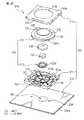
図1は本発明の第1の実施形態によるポインティングデバイス10の分解斜視図、図2はポインティングデバイス10の組立斜視図、図3はポインティングデバイス10の組立断面図である。ポインティングデバイス10は、パーソナルコンピュータ、パーソナルワードプロセッサ等のデータ処理装置や、電子手帳、携帯情報端末(PDA)、携帯電話等の携帯型情報機器において、ディスプレイ上の二次元座標データを指示する補助入力装置として機器筐体に一体的に組み込んだ構成で使用できるものである。
【0049】
ポインティングデバイス10は、基部12と、基部12に対して任意の水平方向へ変位可能に基部12上に支持される操作部14と、操作部14に設置される円板状の磁石(例えば永久磁石)16と、磁石16の近傍で基部12に設置される複数の磁電変換素子(例えばホール素子)18とを備える。操作部14は、磁石16を固定的に保持して基部12上に水平方向へ移動可能に支持される保持部20と、保持部20に連結され、基部12上での保持部20の水平移動に伴い、保持部20を水平移動範囲の原点位置に復帰させる弾性力を発揮する弾性部22とを備える。
【0050】
基部12は、図示しないCPU等の電子部品が実装される回路基板24と、回路基板24に固定的に連結される支持部材26とを備える。支持部材26は、回路基板24の表面24aから離隔した位置に、操作部14の保持部20を任意の水平方向へ摺動自在に支持する支持部分28を有する。なお、この実施形態において「水平方向」とは、回路基板24の略平坦な表面24aに実質的平行な方向を意味する。したがって支持部材26の支持部分28には、回路基板24から離れた側に、回路基板24の表面24aに実質的平行に広がる平坦かつ円形の支持面28aが形成される。支持面28aは、回路基板24の表面24aから突出した位置で、保持部20を任意の水平方向へ摺動自在に支持する。
【0051】
支持部材26にはさらに、支持面28aを囲繞するようにして、操作部14の保持部20の水平移動範囲を規定する円筒壁30が突設される。円筒壁30は、回路基板24の表面24aからの高さが支持面28aよりも高い位置まで突設され、後述するように弾性部22がその一部分で円筒壁30を包囲して支持部材26に取り付けられる。支持面28aの中心を通る円筒壁30の中心軸線は、ポインティングデバイス10の中心軸線Pを構成するとともに、支持面28a上での保持部20の水平移動範囲の原点位置を規定する。また支持部材26の外縁には、円筒壁30の反対側に突出する複数(図では4個)の弾性爪32が形成される。支持部材26は、回路基板24の対応位置に設けられた複数の穴34にそれら弾性爪32をスナップ式に嵌入することにより、回路基板24上の所定位置に固定的に組み付けられる。
【0052】
回路基板24の表面24aには、回路基板24と支持部材26の支持部分28との間に形成される空所の内部で、計4個の磁電変換素子18が中心軸線Pを中心とした等間隔分散配置で実装される。このような磁電変換素子18の配置構成により、ポインティングデバイス10は二次元座標系におけるアナログデータ信号を出力できるようになっている。
【0053】
基部12はさらに、支持部材26の外縁領域を実質的に遮蔽して回路基板24に固定的に連結されるカバー部材36を備える。カバー部材36は、円筒状の外周壁38と、外周壁38の軸線方向一端から径方向内方へ延長される円環状の端壁40とを備え、端壁40の内縁が、後述する操作部14の主要操作部分を水平移動可能に挿通させる中心開口42を画定する。カバー部材36の外周壁38の軸線方向他端には、端壁40の反対側に突出する複数(図では4個)の弾性爪44が一体的に連結される。カバー部材36は、矩形平板状の回路基板24の一組の対向外縁にそれら弾性爪44をスナップ式に嵌着することにより、回路基板24上の所定位置に固定的に組み付けられる。カバー部材36は、中心開口42を通して操作部14の主要操作部分を外方に突出させた状態で、操作部14を基部12から脱落しないように保持する。
【0054】
図示実施形態では、操作部14の保持部20及び弾性部22は、別部材として個別に作製されて、互いに固定的に組み合わされる。保持部20は、操作部14を基部12上で水平移動操作する間に実質的に変形しない程度の剛性を有する段付き円筒状の部材からなり、その軸線方向一端側の大径部分に、磁石16を収容する凹所46が形成される。磁石16は、例えば接着剤を用いたり圧入したりすることにより、保持部20の凹所46に固定できる。保持部20は、凹所46を画定する円筒状の外周壁48の先端(図で下端)を、基部12の支持部材26の支持面28aに一様に当接した状態で、支持面28a上で360°全方位へ摺動しつつ平行移動できる。このような構成は、保持部20と支持面28aとの接触面間の摩擦を低減して、操作部14の水平移動操作性を向上させる点で有利である。
【0055】
弾性部22は、操作部14を基部12上で水平移動操作する間に比較的容易に弾性変形する椀状の部材からなり、保持部20の周囲に隙間を介して延長される主部分50と、主部分50の一端で保持部20に連結される第1連結部分52と、主部分50の他端で基部12に連結される第2連結部分54とを一体に有する。弾性部22の主部分50は、保持部20を実質的全周に渡って囲繞するとともに、無負荷状態で保持部20に対し同軸に配置される円錐台状又はドーム状の輪郭形状を有する。したがって弾性部22は、その主部分50が、基部12上での保持部20の水平移動に伴い弾性変形するとともに、変形量に対応する弾性力を、保持部20の水平移動方向に関わらず一様に発揮する。
【0056】
弾性部22の第1連結部分52は、円錐台状輪郭の主部分50の小径端から軸線方向へ皿状に突出して一体に延長され、その内側に形成される窪みに、保持部20の軸線方向他端側の小径部分56が固定的に嵌入される。弾性部22の第1連結部分52は、例えば接着剤により保持部20の小径部分56に固定できる。第1連結部分52は、保持部20の小径部分56を密接被覆して延び、その外面に、オペレータが操作部14を移動操作する際に例えば手の指先を接触させる操作面58が形成される。
【0057】
弾性部22の第2連結部分54は、円錐台状輪郭の主部分50の大径端から径方向及び軸線方向へフランジ状に突出して一体に延長され、その肉厚部分で、基部12を構成する支持部材26の円筒壁30の外側領域とカバー部材36の外周壁38及び端壁40との間に固定的に挟持かつ掛止される。第1及び第2連結部分52、54は、基部12上で保持部20が水平移動する間に実質的に変形することなく、弾性部22を保持部20及び基部12にそれぞれ固定的に連結する。
【0058】
なお弾性部22は、合成ゴム、天然ゴム等の種々の弾性材料から形成できる。特に、ポインティングデバイス10を搭載対象機器の主回路基板に実装する際にリフロー工程を実施することを考慮すれば、シリコンゴム等の、高温下でも性質が劣化し難い材料から形成することが有利である。
【0059】
上記した各種構成部品を適正に組み合わせた状態で、操作部14は、弾性部22の主部分50及び第1連結部分52を、基部12のカバー部材36の中心開口42に水平移動可能に挿通するとともに、保持部20の小径部分56及びそれを被覆する弾性部22の第1連結部分52を、基部12のカバー部材36の端壁40から外方に突出した位置に配置する。この状態でオペレータは、弾性部22の第1連結部分52に形成される操作面58を、例えば手指により操作して、保持部20を基部12上で水平移動させることができる。
【0060】
図3に示すように、操作部14の弾性部22が平衡状態にあるときには、保持部20及びその凹所46に保持される磁石16の中心軸線Qは、ポインティングデバイス10の中心軸線Pに合致する。この状態で保持部20は、基部12の支持部材26上で水平移動範囲の原点位置に位置決めされ、回路基板24上の4個の磁電変換素子18が磁石16から等距離の位置に配置される。この状態から、図4に示すように、オペレータが操作面58に指先を当接して保持部20を任意の水平方向へ平行移動させると、弾性部22の主部分50が、保持部20の移動方向及び移動距離に対応して、全周に渡り異なる形態の弾性変形を生じる。それにより弾性部22は、主部分50の全体で合力としての弾性力を発揮し、保持部20をその移動方向と反対の方向に付勢する。したがってオペレータは、弾性部22の主部分50が生ずるばね付勢力に抗して、操作部14を水平移動操作することになる。
【0061】
操作部14を図3の原点位置から図4に示す位置に水平移動操作すると、磁石16と各磁電変換素子18との相対的位置関係が変化し、各磁電変換素子18の出力電圧が変動する。各磁電変換素子18の出力電圧の変動は、回路基板24上の図示しないCPUでアナログ情報として処理されてデジタル座標データに変換され、回路基板24に設けられるコネクタ部(図示せず)を介して、搭載対象機器(図示せず)のデータ処理回路に出力される。このようにして、操作部14の保持部20の移動方向及び移動距離に対応して、例えば搭載対象機器のディスプレイ上のカーソルやポインタを所望方向に所望距離だけ移動することができる。
【0062】
図4のデータ入力位置から、オペレータが操作部14から指を離して操作力を解除すると、弾性部22の主部分50が生じているばね付勢力により、直ちに保持部20が磁石16と一体的に原点位置に向けて移動し、弾性部22の主部分50が平衡状態に到達した時点で原点位置に復帰する。なお、保持部20が原点位置に復帰する間に、磁石16の迅速な移動に伴って生じる各磁電変換素子18の出力電圧の急激な変動は、例えばCPUにおける処理フローでキャンセルしてデジタル座標データに変換しないように構成することができる。
【0063】
上記構成を有するポインティングデバイス10によれば、基部12の支持部材26に設けた平坦な支持面28a上で、操作部14の保持部20を移動させる構成としたから、曲面状の支持面を採用した従来の構成に比べて、基部12の外形寸法を削減することができる。また操作部14に、保持部20を水平移動範囲の原点位置に復帰させる弾性部22を設けたから、保持部20を迅速かつ正確に原点位置に復帰させることができ、操作部14の操作性を向上させることができる。しかも弾性部22は、保持部20を実質的全周に渡って囲繞する主部分50で、保持部20の移動方向に関わらず一様な弾性力を発揮する構成であるから、基部と操作部との間に復帰ばねを介在させた従来の構成に比べて、操作性を損なうことなく、特に高さ方向の外形寸法を削減できる。保持部20の小径部分56を被覆する弾性部22の第1連結部分52は、基部12のカバー部材36から外方に突出した位置で操作面58を形成するので、オペレータが基部12上での操作部14の位置を触覚で容易に確認できる利点もある。このように、ポインティングデバイス10は、操作部14の操作性を損なうことなく、電子手帳、携帯情報端末(PDA)、携帯電話等の、手持操作可能な種々の携帯型情報機器への搭載が実現可能な水準まで、外形寸法を削減できる。
【0064】
図5及び図6は、本発明の第2の実施形態によるポインティングデバイス60を、それぞれ分解斜視図及び組立断面図で示す。ポインティングデバイス60は、基部の回路基板に連結される支持部材の構成以外は、前述した第1実施形態によるポインティングデバイス10と実質的同一の構成を有するので、対応する構成要素には共通の参照符号を付してその説明を省略する。
【0065】
ポインティングデバイス60は、基部62と、基部62に対して任意の水平方向へ移動可能に基部62上に支持される操作部14と、操作部14に設置される磁石16と、磁石16の近傍で基部62に設置される複数の磁電変換素子18とを備える。基部62は、図示しないCPU等の電子部品が実装される回路基板24と、回路基板24に固定的に連結される支持部材64と、支持部材64を実質的に遮蔽して回路基板24に固定的に連結されるカバー部材36とから構成される。
【0066】
支持部材64は、円形の中心開口を画定する中空の円筒壁66を備える。さらに支持部材64は、その外縁に沿って、円筒壁66の反対側に突出する複数(図では4個)の弾性爪68を有し、それら弾性爪68により、回路基板24上の所定位置に固定的に組み付けられる。そして回路基板24の表面24aには、支持部材64の円筒壁66に包囲された円形領域に、操作部14の保持部20を任意の水平方向へ摺動自在に支持する平坦な支持面70が形成される。
【0067】
支持部材64の円筒壁66は、回路基板24の表面24aに形成される支持面70内での、操作部14の保持部20の水平移動範囲を規定する。また、支持面70の中心を通る円筒壁66の中心軸線は、ポインティングデバイス60の中心軸線Pを構成するとともに、支持面70上での保持部20の水平移動範囲の原点位置を規定する。保持部20は、大径部分の外周壁48の先端(図で下端)を、回路基板24上の支持面70に一様に当接した状態で、支持面70上で360°全方位へ摺動しつつ平行移動できる。そして、4個の磁電変換素子18は、支持面70の反対側に位置する回路基板24の裏面24bに、中心軸線Pを中心とした等間隔分散配置で実装される。
【0068】
ポインティングデバイス60は、前述したポインティングデバイス10と同様にして、基部62上で操作部14を水平移動操作することにより、アナログデータを入力することができる。このとき、操作部14に設けた弾性部22の作用により、保持部20を水平移動範囲の原点位置に迅速かつ正確に復帰させることができる。特にポインティングデバイス60では、基部62の回路基板24の表面24aに直接、操作部14の保持部20を搭載するとともに、磁電変換素子18を回路基板24の裏面24bに実装しているので、前述したポインティングデバイス10に比べて、高さ方向の寸法を一層効果的に削減することができる。
【0069】
なお上記構成では、支持部材64は、上記したように保持部20の水平移動範囲を規定するとともに、カバー部材36と協働して弾性部22の第2連結部分54を固定的に挟持するように作用する。したがって、カバー部材36の中心開口42の寸法を調整して中心開口42により保持部20の水平移動範囲を規定できるように構成するとともに、弾性部22の第2連結部分54とカバー部材36の連結強度を例えば一体成形等により向上させることによって、支持部材64を省略することもできる。
【0070】
図7及び図8は、本発明の第3の実施形態によるポインティングデバイス80を、それぞれ分解斜視図及び組立断面図で示す。ポインティングデバイス80は、基部の回路基板に連結される支持部材の構成と、クリック機能を付加するためのスイッチ機構を内蔵した構成以外は、前述した第1実施形態によるポインティングデバイス10と実質的同一の構成を有するので、対応する構成要素には共通の参照符号を付してその説明を省略する。
【0071】
ポインティングデバイス80は、基部82と、基部82に対して任意の水平方向へ移動可能に基部82上に支持される操作部14と、操作部14に設置される磁石16と、磁石16の近傍で基部82に設置される複数の磁電変換素子18と、基部82と操作部14との間に配置されるスイッチ機構84とを備える。基部82は、図示しないCPU等の電子部品が実装される回路基板24と、回路基板24に固定的に連結される支持部材86と、支持部材86の外縁領域を実質的に遮蔽して回路基板24に固定的に連結されるカバー部材36とを備える。支持部材86は、回路基板24の表面24aから離隔した位置に、操作部14の保持部20を任意の水平方向へ摺動自在に支持する支持部分を構成する複数(図では4個)の弾性梁部分88を有する。支持部材86のそれら弾性梁部分88には、回路基板24から離れた側に、無負荷状態で回路基板24の表面24aに実質的平行に広がる平坦な支持面88aがそれぞれ形成される。
【0072】
支持部材86の複数の弾性梁部分88は、ポインティングデバイス80の中心軸線Pを中心として放射状に配置され、それらの径方向外端を支点として、互いに独立して弾性的に変位できる。各弾性梁部分88の基端すなわち径方向外端には、各々の支持面88aを囲繞するようにして、操作部14の保持部20の水平移動範囲を規定する円弧壁90がそれぞれ突設される。それら円弧壁90は、中心軸線Pを中心とする同一円周上に配置され、中心軸線Pが、複数の支持面88a上での保持部20の水平移動範囲の原点位置を規定する。保持部20は、大径部分の外周壁48の先端(図で下端)を、複数の弾性梁部分88の支持面88aに一様に当接した状態で、それら支持面88a上で360°全方位へ摺動しつつ平行移動できる。
【0073】
また、複数の弾性梁部分88のうちで所望の1つの弾性梁部分88には、その径方向内端の自由端に、支持面88aの反対側に局部的に隆起する押圧点92が形成される。押圧点92は、ポインティングデバイス80の中心軸線P上に整合して配置される。支持部材86は、その外縁に設けた複数(図では4個)の弾性爪94により、回路基板24上の所定位置に固定的に組み付けられる。
【0074】
回路基板24の表面24aには、回路基板24と支持部材86の複数の弾性梁部分88との間に形成される空所の内部で、クリック機能を付加するためのスイッチ機構84が実装される。スイッチ機構84は、可動接点と固定接点とを有する周知の開閉構造を備え、それら両接点がポインティングデバイス80の中心軸線Pに実質的に整合する位置に配置される。すなわち、スイッチ機構84の可動接点は、支持部材86の1つの弾性梁部分88に設けた押圧点92の直下に位置決めされる。そして、4個の磁電変換素子18は、スイッチ機構84の反対側に位置する回路基板24の裏面24bに、中心軸線Pを中心とした等間隔分散配置で実装される。
【0075】
なお、スイッチ機構84の構成は任意であり、可動接点がばねに担持されるメカニカルスイッチや、一対のフレキシブル回路基板を有するメンブレンスイッチ等、様々なものを採用できる。また、スイッチ機構84の外形寸法によっては、複数の磁電変換素子18を、回路基板24と複数の弾性梁部分88との間の空所内に設置することもできる。
【0076】
ポインティングデバイス80は、前述したポインティングデバイス10と同様にして、基部82上で操作部14を水平移動操作することにより、アナログデータを入力することができる。このとき、操作部14に設けた弾性部22の作用により、保持部20を水平移動範囲の原点位置に迅速かつ正確に復帰させることができる。さらにポインティングデバイス80では、図8に示す原点位置において、オペレータが操作部14の操作面58を例えば指先で押下して、保持部20の外周壁48の下端を複数の弾性梁部分88に押し付けることにより、それら弾性梁部分88の下方に位置するスイッチ機構84を閉成させることができる。この実施形態では、図9に示すように、操作部14を押下することにより、各弾性梁部分88が径方向外端を支点に弾性的に撓み、1つの弾性梁部分88に設けた押圧点92がその直下のスイッチ機構84を押圧して作動させる。
【0077】
スイッチ機構84が閉成作動すると、回路基板24上のCPUがクリック信号として処理して、搭載対象機器のデータ処理回路に出力する。このようにして、操作部14を原点位置で押下することにより、例えば搭載対象機器のディスプレイ上のポインタに関連してクリック操作を実施することができる。そして図9の押下位置から、オペレータが押下力を解除すると、複数の弾性梁部分88が弾性的に復原して、スイッチ機構84が開成されるとともに、操作部14が図8の原点位置に復帰する。なお、操作部14の水平移動操作中に、オペレータが操作部14に負荷する操作力によってスイッチ機構84を不用意に作動させてしまわないようにするために、支持部材86の材料や弾性梁部分88の寸法を適宜選択してそれら弾性梁部分88の弾性力を調整することが望ましい。
【0078】
上記したスイッチ機構を有するポインティングデバイスは、他の構成によっても実現できる。図10及び図11は、そのような本発明の第4の実施形態によるポインティングデバイス100を、それぞれ分解斜視図及び組立断面図で示す。ポインティングデバイス100は、基部の回路基板に連結されてスイッチ機構を作動させる支持部材の構成以外は、前述した第3実施形態によるポインティングデバイス80と実質的同一の構成を有するので、対応する構成要素には共通の参照符号を付してその説明を省略する。
【0079】
ポインティングデバイス100は、基部102と、基部102に対して任意の水平方向へ移動可能に基部102上に支持される操作部14と、操作部14に設置される磁石16と、磁石16の近傍で基部102に設置される複数の磁電変換素子18と、基部102と操作部14との間に配置されるスイッチ機構84とを備える。基部102は、図示しないCPU等の電子部品が実装される回路基板24と、回路基板24に固定的に連結される第1支持部材104と、弾性部材106を介して第1支持部材104上に弾性変位可能に支持される第2支持部材108と、第1支持部材104を実質的に遮蔽して回路基板24に固定的に連結されるカバー部材36とを備える。
【0080】
第1支持部材104は、同心かつ周方向等間隔に配置される複数の円弧壁110を備え、それら円弧壁110によって円形の中心開口を画定する。さらに第1支持部材104は、その外縁に沿って、各円弧壁110の反対側に突出する複数(図では4個)の弾性爪112を有し、それら弾性爪112により、回路基板24上の所定位置に固定的に組み付けられる。例として圧縮コイルばねからなる弾性部材106は、第1支持部材104の複数の円弧壁110を同心状に取り巻いて配置される。
【0081】
第2支持部材108は、円板状の支持部分114と、支持部分114の外縁に沿って周方向等間隔に配置され、径方向外方へ延設される複数(図では4個)のフランジ部分116とを備える。第2支持部材108の支持部分114は、第1支持部材104の複数の円弧壁110によって画定される中心開口にがたつき無く軸線方向摺動自在に収容される寸法及び形状を有する。また、複数のフランジ部分116は、第1支持部材104の周方向へ隣り合う円弧壁110の間に各々ががたつき無く軸線方向摺動自在に受容される寸法及び形状を有する。
【0082】
第2支持部材108を第1支持部材104に適正に組み付けた状態で、複数のフランジ部分116は、複数の円弧壁110を取り巻いて配置された弾性部材106の上端に載せられる。この状態で、第2支持部材108の支持部分114は、回路基板24の表面24aから離隔した位置に配置される。支持部分114には、回路基板24から離れた側に、弾性部材106が無負荷の状態で回路基板24の表面24aに実質的平行に広がる平坦かつ円形の支持面114aが形成される。
【0083】
第2支持部材108の複数のフランジ部分116は、支持面114aを囲繞する円弧面をそれぞれに有し、第1支持部材104の複数の円弧壁110と協働して、操作部14の保持部20の水平移動範囲を規定する。支持面114aの中心を通るそれら円弧壁110の中心軸線は、ポインティングデバイス100の中心軸線Pを構成するとともに、支持面114a上での保持部20の水平移動範囲の原点位置を規定する。また、第2支持部材108の支持部分114には、中心軸線P上で支持面114aの反対側に局部的に隆起する押圧点118が形成される。保持部20は、その大径部分の外周壁48の先端(図で下端)を、第2支持部材108の支持面114aに一様に当接した状態で、支持面114a上で360°全方位へ摺動しつつ平行移動できる。
【0084】
ポインティングデバイス100は、前述したポインティングデバイス10と同様にして、基部102上で操作部14を水平移動操作することにより、アナログデータを入力することができる。このとき、操作部14に設けた弾性部22の作用により、保持部20を水平移動範囲の原点位置に迅速かつ正確に復帰させることができる。さらにポインティングデバイス100では、図11に示す原点位置において、オペレータが操作部14の操作面58を例えば指先で押下して、保持部20の外周壁48の下端を第2支持部材108の支持部分114に押し付けることにより、支持部分114の下方に位置するスイッチ機構84を閉成させることができる。この実施形態では、図12に示すように、操作部14を押下することにより、弾性部材106が第2支持部材108の複数のフランジ部分116を介して弾性的に圧縮され、支持部分114に設けた押圧点118がその直下のスイッチ機構84を押圧して作動させる。
【0085】
そして図12の押下位置から、オペレータが押下力を解除すると、弾性部材106が弾性的に復原して、スイッチ機構84が開成されるとともに、操作部14が図11の原点位置に復帰する。なお、操作部14の水平移動操作中に、オペレータが操作部14に負荷する操作力によってスイッチ機構84を不用意に作動させてしまわないようにするために、弾性部材106のばね定数を適宜調整することが望ましい。
【0086】
上記した各実施形態によるポインティングデバイス10、60、80、100には、様々な修正及び変形を施すことができる。例えば、操作部14は、異種材料から別部材として個別に作製した保持部20及び弾性部22を互いに固定的に組み合わせた上記構成に代えて、図13に示すように、保持部20と弾性部22とを異種材料から一体的に成形した構成を採用することもできる。図13に示すポインティングデバイス10の変形例では、同一又は異なる樹脂材料から予め個別に成形された保持部20及びカバー部材36に対し、インサート成形工程により、ゴム材料からなる弾性部22を一体成形している。このような構成によれば、弾性部22の第1連結部分52と保持部20の小径部分56との連結強度を向上させることができるとともに、弾性部22をその第2連結部分54でカバー部材36と一体化できるので組立作業が容易になる利点がある。
【0087】
この場合、図14に示すように、保持部20がその小径部分56で、弾性部22の第1連結部分52を貫通して外部に突出し、その突出部分120に、別部材として形成したキートップ122を装着する構成とすることもできる。キートップ122の外面には、オペレータが操作部14を移動操作する際に例えば手の指先を接触させる操作面124が形成される。この構成では、上記したように保持部20と弾性部22とを一体的に成形することにより、保持部20の小径部分56と弾性部22の第1連結部分52との十分な連結強度を確保することができる。また、キートップ122の裏側に設けた凹部126に保持部20の突出部分120を圧入するだけで、キートップ122を保持部20に強固に固定的に連結することができる。この構成によれば、キートップ122の外面に種々の符号や図柄を印刷したり、キートップ122を着色したりすることにより、ポインティングデバイスの意匠性を向上させることができる。
【0088】
或いは、図15に示すように、保持部20と弾性部22とを同一のゴム材料から一体成形することにより、操作部14を作製することもできる。この構成によれば、操作部14の部品点数が削減され、組立作業性が向上する。また、弾性部22の第1連結部分52における保持部20との組付強度を考慮する必要が無いので、操作部14の小形化を一層促進することができる。
【0089】
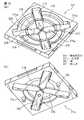
また、図16〜図20に示すように、弾性部による原点位置復帰機能を補助するための補助弾性部を、基部と操作部との間に配置することもできる。例えば、図16及び図17に示すポインティングデバイス10の変形例では、基部12の支持部材26と操作部14の保持部20との間に、補助弾性部として機能する板ばね128が設置されている。板ばね128は、円環状の基礎部分130と、基礎部分130の内周縁に沿って等間隔に配置され、中心軸線Pに向けて凸状に湾曲して径方向内方へ延設される複数(図では4個)の腕部分132とを有する。板ばね128の基礎部分130は、支持部材26の円筒壁30の内面に一様に接触して支持面28a上に搭載される寸法及び形状を有する。
【0090】
ポインティングデバイス10の構成部品を適正に組み合わせた状態で、板ばね128の複数の腕部分132は、それらの自由端で、保持部20の大径部分の外周壁48に当接される。そして、弾性部22と板ばね128との双方が平衡状態にあるときに、操作部14は基部12上で原点位置に位置決めされる(図17)。操作部14を図17の原点位置から水平移動操作すると、弾性部22の主部分50及び板ばね128の任意の腕部分132が、保持部20の移動方向及び移動距離に対応して弾性変形し、それにより保持部20をその移動方向と反対の方向に付勢する(図18)。
【0091】
図18のデータ入力位置から、オペレータが操作部14から指を離して操作力を解除すると、弾性部22の主部分50及び板ばね128の腕部分132が生じているばね付勢力により、直ちに保持部20が磁石16と一体的に原点位置に向けて移動し、弾性部22及び板ばね128の双方が平衡状態に到達した時点で原点位置に復帰する。このように、補助弾性部として板ばね128を用いることにより、保持部20を水平移動範囲の原点位置にさらに迅速かつ正確に復帰させることができる。また、ゴム製の弾性部22の経年劣化による操作性の低下を、板ばね128の作用により抑制することができる。
【0092】
上記した板ばね128の代わりに、図19及び図20に示すように、平坦形状に巻かれたコイルばね134を、補助弾性部として使用することもできる。この場合、コイルばね134は、その外方端136で支持部材26の円筒壁30の内面に嵌着され、その内方端138で、保持部20の大径部分の外周壁48に嵌着される。なお、保持部20の外周壁48の下端には、コイルばね134の内方端138を掛止するビード140を形成することが好ましい。そして、弾性部22とコイルばね134との双方が平衡状態にあるときに、操作部14は基部12上で原点位置に位置決めされる(図20)。操作部14を図20の原点位置から水平移動操作すると、弾性部22の主部分50及びコイルばね134が、保持部20の移動方向及び移動距離に対応して弾性変形し、それにより保持部20をその移動方向と反対の方向に付勢する。
【0093】
以上、説明したように、本発明に係る磁電変換素子型のポインティングデバイスは、その外形寸法を、操作部の操作性を損なうことなく、電子手帳、携帯情報端末(PDA)、携帯電話等の手持操作可能な携帯型情報機器へ搭載可能な水準まで削減できる。ところで、このような携帯型情報機器にポインティングデバイスを搭載する場合には、機器筐体の狭小な内部空間で、ポインティングデバイスと搭載対象機器の主回路基板(実装基板)との電気的及び機械的接続を確実かつ安定的に実現することが要求されている。
【0094】
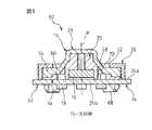
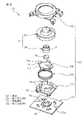
図21及び図22は、そのような高機能の電気的接続構造及び機械的接続構造を有する本発明の第5の実施形態によるポインティングデバイス150を示す。なおポインティングデバイス150は、電気的及び機械的接続構造の構成以外は、前述した第3実施形態によるポインティングデバイス80と実質的同一の構成を有するものとし、対応する構成要素には共通の参照符号を付してその説明を省略する。
【0095】
ポインティングデバイス150は、基部82の回路基板24に実装された磁電変換素子18及びスイッチ機構84を、搭載対象機器の主回路基板(実装基板)Mに電気的に接続するための2個のコネクタ152を備える。各コネクタ152は、絶縁部材154と、絶縁部材154に等間隔配置で整列支持される複数の端子156とを備える。矩形平板状の回路基板24の外縁近傍領域には、カバー部材36の弾性爪44を嵌着しない側の一組の対向外縁に沿って、複数のスルーホール158が、コネクタ152の端子156に対応する等間隔配置で整列してそれぞれ形成される。それらスルーホール158は、回路基板24上の磁電変換素子18及びスイッチ機構84に例えば印刷回路を介して電気的に接続される。
【0096】
各コネクタ152の絶縁部材154は、樹脂材料から一体成形される角棒状部材であり、例えばインサート成形工程により複数の端子156を埋設した状態に成形される。各端子156は、プレス工程により打ち抜いたピン状金属片をL字状に屈曲して形成される。各端子156は、その一端156aを絶縁部材154の頂面154aから突出させるとともに、他端156bを絶縁部材154の側面154bから突出させて、絶縁部材154に固定的に支持される。各コネクタ152の絶縁部材154の頂面154aには、端子配列方向の両端部位に、それぞれ位置決め突起160が形成される。他方、回路基板24には、各列のスルーホール158の配列方向両側に、位置決め突起160を受容する位置決め孔162が形成される。
【0097】
各コネクタ152は、絶縁部材154に設けた位置決め突起160を回路基板24の対応の位置決め孔162に嵌入するとともに、複数の端子156の一端156aを回路基板24の対応のスルーホール158に個別に挿入した状態で、回路基板24に装着される。このとき各コネクタ152は、複数の端子116の他端116bが回路基板24の外方へ張り出すように方向付けされる。この状態で、各端子156はその一端156aで、はんだ164により各スルーホール158に固着されて、磁電変換素子18及びスイッチ機構84に電気的に接続される。また各コネクタ152は、複数の端子156の他端156bを、実装基板Mの表面に設けた複数の電極(図示せず)にそれぞれ位置合せした状態で、はんだ166を介して実装基板Mに実装される。
【0098】
このように、上記構成を有するコネクタ152は、棒状の絶縁部材154に複数の端子156を埋設した極めて単純な構成を有するので、小形化及び狭ピッチ化が容易である利点を有する。しかも、回路基板24に設けた対応のスルーホール158に各端子156を固定するようにしたから、例えば電極パッドに端子をはんだ付けする構成に比べて、回路基板24上で各端子156の固定に要する面積を効果的に縮減できる利点がある。したがって、携帯型情報機器にポインティングデバイス150を搭載する場合に、機器筐体の狭小な内部空間で、ポインティングデバイス150と情報機器の主回路基板との電気的接続を確実かつ安定的に実現することが可能になる。
【0099】
なお、図示実施形態では、ポインティングデバイス150の一対のコネクタ152と実装基板Mとの間のはんだ付けによる電気的及び機械的接続を補強するための機械的連結構造として、一対の取付部材168が使用されている。各取付部材168は、例えば板金材料から打ち抜きかつ折曲して形成され、一端のフック部分170と他端の脚部分172とを一体に有する。他方、基部82の支持部材86には、その外縁に沿って互いに対向する位置に、一対のフック受け174が延長形成されている。
【0100】
ポインティングデバイス150を実装基板Mに実装する際には、上記したように各コネクタ152をはんだ付けした後に、一対の取付部材168を、各々のフック部分170を対応のフック受け174に掛着して支持部材86に取り付ける。その状態で、各取付部材168の脚部分172を、はんだ176によって実装基板Mの表面の所望位置に固定する。このようにして、ポインティングデバイス150は、オペレータが操作部14に負荷する力に抗して、実装基板M上に強固に固定保持される。
【0101】
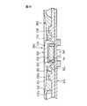
ポインティングデバイス150においては、回路基板24に形成される複数のスルーホール158に対し、回路基板24上で種々の電子部品を実装するために要する実装面積を効果的に拡大し得る特殊な形状のランドを形成することができる。例えば図23に示すように、回路基板24の各スルーホール158の開口縁158aに隣接して、開口縁158aと回路基板24の外縁24cとの間の部分でそれ以外の部分よりも狭い幅を有するランド178を、回路基板24の表面24aに形成することができる。このような形状のランド178を採用すれば、スルーホール158を回路基板24の外縁24cに可及的に近接して形成できるので、回路基板24上の電子部品実装面積を効果的に拡大できる。
【0102】
このような特徴的形状のランド178を有するスルーホール158に接続されたコネクタ152を備える回路基板24は、以下の方法で作製することが有利である。
まず、図24に示すように、図示しない電子部品を実装するための矩形の実装領域180と、実装領域180の両側に隣接する一対の捨て領域182とを有する回路基板24を用意する。このような捨て領域182は、電子部品の実装や回路の形成を行わない領域であって、一般的な基板実装工程で回路基板を搬送する際の支持及び位置決め用に使用されるものとして知られている。
【0103】
次いで、回路基板24の実装領域180に、各々の円環状のランド178が実装領域180から捨て領域182まで連続して広がるようにして、複数のランド付きスルーホール158を、実装領域180と捨て領域182との境界線184に沿って形成する。ここで、各スルーホール158は、例えば図25(a)に示すような、回路基板24の両面にランド178を有する両面めっきスルーホールとして、一般的な印刷回路板の製造方法によって形成することができる。さらに、スルーホール158を形成した後に、回路基板24の両面に、境界線184に沿って延びる溝186(図25(b))を形成することが有利である。
【0104】
次に、コネクタ152の複数の端子156を、それらの一端156aで、複数のスルーホール158に個別に挿入して、対応のランド178にはんだ付けする。それにより一対のコネクタ152を、捨て領域182を有する回路基板24の実装領域180に固定する。最後に、各コネクタ152を実装領域180に取り付けたままの状態で、境界線184上に形成した溝186に沿って、捨て領域182を実装領域180から折り取って分離する。このようにして、図26に示すように、一組の対向外縁24cに沿って取り付けた一対のコネクタ152を有する回路基板24が作製される。
【0105】
なお、上記したランド付きスルーホール158は、はんだ164による端子固着強度を確保できることを前提に、回路基板24の外縁24cに部分的に開口するような形状とすることもできる。この場合、各スルーホール158には、C形状のランドが形成されることになる。
【0106】
以上、図面を参照して幾つかの好適な実施形態を説明したが、本発明は、それら図示実施形態以外の様々な形態を採ることができる。例えば、本発明に係るポインティングデバイスの操作部の特徴的構成は、磁石16と複数の磁電変換素子18との位置関係が、図示実施形態とは逆の構成、すなわち基部12、62、82、102に設置した磁石16に対し、操作部14に設置した磁電変換素子18が変位するように構成されたポインティングデバイスにおいても、有効に採用でき、かつ同様に格別の作用効果を奏するものである。また、上記したコネクタ付き回路基板の製造方法は、上記したポインティングデバイス150への適用に限らず、他の様々な電子機器における回路基板接続構造に適用できるものである。
【0107】
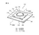
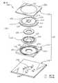
ところで、本発明に係る磁電変換素子型のポインティングデバイスは、例えば、ディスプレイ部とキーボード部とが互いに蝶番連結された折り畳み可能な携帯型情報機器(例えば携帯電話)に搭載することができる。この場合、ポインティングデバイスを含む各種スイッチ類の、キーボード部表面からの突出量を極力低減することが、折り畳み時の機器全体の厚みを削減して携帯性を一層向上させる観点で望ましい。図27〜図29は、このような携帯型情報機器のキーボード部に好適に搭載可能な低背構造を有する本発明の第6の実施形態によるポインティングデバイス190を示す。なおポインティングデバイス190は、前述した第1実施形態によるポインティングデバイス10と機能的に実質的同一の基本構造を有するものである。
【0108】
ポインティングデバイス190は、基部192と、基部192に対して任意の水平方向へ移動可能に基部192上に支持される操作部194と、操作部194に設置される円板状の磁石(例えば永久磁石)196と、磁石196の近傍で基部192に設置される複数の磁電変換素子(例えばホール素子)198とを備える。操作部194は、磁石196を固定的に保持して基部192上に水平方向へ移動可能に支持される保持部200と、保持部200に連結され、基部192上での保持部200の水平移動に伴い、保持部200を水平移動範囲の原点位置に復帰させる弾性力を発揮する弾性部202とを備える。
【0109】
基部192は、図示しないCPU等の電子部品が実装される回路基板204と、回路基板204に固定的に連結される支持部材206とを備える。支持部材206は、平面視で略正方形の板状部材であり、回路基板204の表面204aに隙間を介さずに搭載されるとともに、その中央の略円形の凹状領域に、操作部194の保持部200を任意の水平方向へ摺動自在に支持する支持部分208を有する。なお、この実施形態において「水平方向」とは、回路基板204の略平坦な表面204aに実質的平行な方向を意味する。したがって支持部材206の支持部分208には、回路基板204から離れた側に、回路基板204の表面204aに実質的平行に広がる平坦かつ円形の支持面208aが形成される。支持面208aは、回路基板204の表面204aから突出した位置で、保持部200を任意の水平方向へ摺動自在に支持する。
【0110】
支持部材206にはさらに、支持面208aを囲繞するようにして、操作部194の保持部200の水平移動範囲を規定する円筒壁210が突設される。円筒壁210は、回路基板204の表面204aからの高さが支持面208aよりも高い位置まで突設され、後述するように弾性部202がその一部分で円筒壁210を包囲して支持部材206に取り付けられる。支持面208aの中心を通る円筒壁210の中心軸線は、ポインティングデバイス190の中心軸線Pを構成するとともに、支持面208a上での保持部200の水平移動範囲の原点位置を規定する。また支持部材206の支持部分208には、その略中央で支持面208a及び円筒壁210の反対側に突出する1個の位置決めピン212が形成される。支持部材206は、回路基板204の対応位置に設けられた穴214に位置決めピン212を嵌入することにより、回路基板204上の所定位置に固定的に組み付けられる。なお、支持部材206を回路基板204に強固に固定するために、接着剤を補助的に用いることもできる。
【0111】
回路基板204の表面204aの反対側(すなわち裏面204b)には、計4個の磁電変換素子198が、中心軸線Pを中心とした等間隔分散配置で実装される。このような磁電変換素子198の配置構成により、ポインティングデバイス190は二次元座標系におけるアナログデータ信号を出力できるようになっている。
【0112】
基部192はさらに、支持部材206の外縁領域206aを実質的に遮蔽して支持部材206に固定的に連結されるカバー部材216を備える。カバー部材216は、支持部材206に対応する平面視略正方形状を有する薄板状部材であり、その端板部分216aの中央領域に、後述する操作部194の主要操作部分を水平移動可能に挿通させる略円形の中心開口218を有する。カバー部材216の外縁には、四辺に沿ってそれぞれ延長片220が端板部分216aに略直交する方向へ延設され、各延長片220に、板厚方向へ貫通する取付孔222が貫通形成される。カバー部材216は、支持部材206の四辺に沿って側方へ突設された複数の爪224を、それら延長片220の対応の取付孔222に、各延長片220の弾性変形を利用してスナップ式に嵌着することにより、支持部材206に固定的に組み付けられる。カバー部材216は、中心開口218を通して操作部194の主要操作部分を外方に突出させた状態で、操作部194を基部192から脱落しないように保持する。なお、このような構成を有するカバー部材216は、所望の板金材料から作製できる。
【0113】
図示実施形態では、操作部194の保持部200及び弾性部202は、別部材として個別に作製されて、互いに固定的に組み合わされる。保持部200は、操作部194を基部192上で水平移動操作する間に実質的に変形しない程度の剛性を有する中空円筒状の部材からなり、その円筒状の外周壁226の内側に、磁石196を収容する空洞部226aが形成される。磁石196は、例えば接着剤を用いたり圧入したりすることにより、保持部200の空洞部226aに固定できる。保持部200は、外周壁48の軸線方向一端(図で下端)に径方向外方へ延設したフランジ部分228の軸線方向端面を、基部192の支持部材206の支持面208aに一様に当接した状態で、支持面208a上で360°全方位へ摺動しつつ平行移動できる。このような構成は、保持部200と支持面208aとの接触面間の摩擦を低減して、操作部194の水平移動操作性を向上させる点で有利である。
【0114】
保持部200には、磁石196と弾性部202との間に介在するヨーク230が取り付けられる。ヨーク230は、平面視で略円形の蓋状部材であり、その円板状の端壁部分230aで、保持部200に収容された磁石196を一面(図で上面)から遮蔽するとともに、端壁部分230aの外縁から延設される円筒状の周壁部分230bで、保持部200の外周壁226を包囲して保持部200に取り付けられる。ヨーク230は、例えば接着剤を用いたり圧入したりすることにより、保持部200の外周壁226に固定できる。ヨーク230は所望の磁性金属材料からなり、磁石196と磁電変換素子198との間で磁路を積極的に閉じることにより、弾性部202を通した外部への磁気漏洩を防止するように作用する。このようなヨーク230は、低背型のポインティングデバイス190に特に有効に装備されるものである。
【0115】
弾性部202は、操作部194を基部192上で水平移動操作する間に比較的容易に弾性変形する椀状の部材からなり、保持部200の周囲に隙間を介して延長される主部分232と、主部分232の一端で保持部200に連結される第1連結部分234と、主部分232の他端で基部192に連結される第2連結部分236とを一体に有する。弾性部202の主部分232は、保持部200を実質的全周に渡って囲繞するとともに、無負荷状態で保持部200に対し同軸に配置される円錐台状又はドーム状の輪郭形状を有する。したがって弾性部202は、その主部分232が、基部192上での保持部200の水平移動に伴い弾性変形するとともに、変形量に対応する弾性力を、保持部200の水平移動方向に関わらず一様に発揮する。
【0116】
弾性部202の第1連結部分234は、円錐台状輪郭の主部分232の小径端から軸線方向へ皿状に突出して一体に延長され、その内側に形成される窪みに、保持部200に取り付けたヨーク230が固定的に嵌入される。弾性部202の第1連結部分234は、例えば接着剤を用いたり圧入したりすることによりヨーク230に固定できる。第1連結部分234は、ヨーク230の端壁部分230a及び周壁部分230bを密接被覆して延び、その外面に、オペレータが操作部194を移動操作する際に例えば手の指先を接触させる操作面238が形成される。
【0117】
弾性部202の第2連結部分236は、円錐台状輪郭の主部分232の大径端から径方向及び軸線方向へフランジ状に突出して一体に延長され、その肉厚部分で、基部192を構成する支持部材206の円筒壁210の外側環状溝領域210aとカバー部材216の端板部分216aとの間に固定的に挟持かつ掛止される。第1及び第2連結部分234、236は、基部192上で保持部200が水平移動する間に実質的に変形することなく、弾性部202を保持部200及び基部192にそれぞれ固定的に連結する。
【0118】
なお弾性部202は、合成ゴム、天然ゴム等の種々の弾性材料から形成できる。特に、ポインティングデバイス190を搭載対象機器の主回路基板に実装する際にリフロー工程を実施することを考慮すれば、シリコンゴム等の、高温下でも性質が劣化し難い材料から形成することが有利である。
【0119】
上記した各種構成部品を適正に組み合わせた状態で、操作部194は、弾性部202の主部分232及び第1連結部分234を、基部192のカバー部材216の中心開口218に水平移動可能に挿通するとともに、ヨーク230を介して保持部200に連結される弾性部202の第1連結部分234を、基部192のカバー部材216の端板部分216aから外方に突出した位置に配置する。この状態でオペレータは、弾性部202の第1連結部分234に形成される操作面238を、例えば手指により操作して、保持部200を基部192上で水平移動させることができる。
【0120】
図29に示すように、操作部194の弾性部202が平衡状態にあるときには、保持部200及びその空洞部226aに保持される磁石196の中心軸線Qは、ポインティングデバイス190の中心軸線Pに合致する。この状態で保持部200は、基部192の支持部材206上で水平移動範囲の原点位置に位置決めされ、回路基板204上の4個の磁電変換素子198が磁石196から等距離の位置に配置される。この状態から、オペレータが操作面238に指先を当接して保持部200を任意の水平方向へ平行移動させると、弾性部202の主部分232が、保持部200の移動方向及び移動距離に対応して、全周に渡り異なる形態の弾性変形を生じる。それにより弾性部202は、主部分232の全体で合力としての弾性力を発揮し、保持部200をその移動方向と反対の方向に付勢する。したがってオペレータは、弾性部202の主部分232が生ずるばね付勢力に抗して、操作部194を水平移動操作することになる。
【0121】
このように、ポインティングデバイス190は、前述したポインティングデバイス10における基部12及び操作部14と機能的に同一の基部192および操作部194を備えるので、ポインティングデバイス10と同様の操作により、操作部194の移動方向及び移動距離に対応したアナログ情報を入力することができる。しかも、基部192及び操作部194を構成する各構成要素を薄型化するとともに、磁電変換素子198を回路基板204の裏面204bに実装する構成としたから、ポインティングデバイス10に比べて、全体として低背化を実現したポインティングデバイス190が提供される。
【0122】
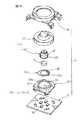
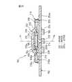
図30〜図32は、ポインティングデバイス190に比べてさらなる低背化を可能にする本発明の第7の実施形態によるポインティングデバイス240を示す。ポインティングデバイス240は、基部の回路基板に連結される支持部材の構成以外は、前述した第6実施形態によるポインティングデバイス190と実質的同一の構成を有するので、対応する構成要素には同一の参照符号を付してその説明を省略する。
【0123】
ポインティングデバイス240は、基部242と、基部242に対して任意の水平方向へ変位可能に基部242上に支持される操作部194と、操作部194に設置される磁石196と、磁石196の近傍で基部242に設置される複数の磁電変換素子198とを備える。基部242は、図示しないCPU等の電子部品が実装される回路基板204と、回路基板204に固定的に連結される支持部材244と、支持部材244の外縁領域244aを実質的に遮蔽して支持部材244に固定的に連結されるカバー部材216とから構成される。
【0124】
支持部材244は、平面視で略正方形の板状部材であり、回路基板204の表面204aに隙間を介さずに搭載されるとともに、その中央の略円形の凹状領域に、操作部194の保持部200を任意の水平方向へ摺動自在に支持する支持部分246を有する。支持部材244の支持部分246には、回路基板204から離れた側に、回路基板204の表面204aに実質的平行に広がる平坦かつ円形の支持面246aが形成される。支持面246aは、回路基板204の表面204aから突出した位置で、保持部200を任意の水平方向へ摺動自在に支持する。
【0125】
支持部材244はさらに、回路基板204の表面204aからの高さが支持面246aよりも低い位置まで凹設され、支持面246aを囲繞する方向に円弧状に延びる複数(図では4個)の溝248を有する。図示実施形態では、支持部材244の支持部分246と外縁領域244aとが、支持面246aの周方向へ等間隔配置された複数(図では4個)の連結片250のみによって互いに一体的に連結され、それにより、支持面246aを囲繞する同一円周上に、連結片250を介して互いに分離された複数の溝248が、板厚方向へ貫通形成される。
【0126】
支持面246aの中心を通る複数の溝248の中心軸線は、ポインティングデバイス240の中心軸線Pを構成するとともに、支持面246a上での保持部200の水平移動範囲の原点位置を規定する。保持部200は、そのフランジ部分228の軸線方向端面を、支持部材244の支持面246aに一様に当接した状態で、支持面246a上で360°全方位へ摺動しつつ平行移動できる。
【0127】
また、支持部材244の支持部分246には、その略中央で支持面246aの反対側に突出する1個の位置決めピン252が形成される。支持部材244は、回路基板204の対応位置に設けられた穴214に位置決めピン252を嵌入することにより、回路基板204上の所定位置に固定的に組み付けられる。なお、カバー部材216は、支持部材244の四辺に沿って側方へ突設された複数の爪254を、各延長片220の対応の取付孔222にスナップ式に嵌着することにより、支持部材244に固定的に組み付けられる。
【0128】
支持部材244の複数の溝248には、弾性部202の第2連結部分236が挿入される。すなわち、弾性部202の第2連結部分236は、その肉厚部分で、支持部材244の複数の溝248とカバー部材216の端板部分216aとの間に固定的に挟持かつ掛止される。したがって、弾性部202の第2連結部分236には、支持部材244の複数の連結片250に対応する位置に、連結片250を受容する切欠き236aが形成される。弾性部202の第1及び第2連結部分234、236は、基部242上で保持部200が水平移動する間に実質的に変形することなく、弾性部202を保持部200及び基部242にそれぞれ固定的に連結する。
【0129】
ポインティングデバイス240は、前述したポインティングデバイス190と同様にして、基部242上で操作部194を水平移動操作することにより、アナログデータを入力することができる。特にポインティングデバイス240では、基部242を構成する支持部材244に、ポインティングデバイス190で支持部材206に設けた円筒壁210の代わりに、支持面246aよりも低い位置まで凹設される複数の溝248を形成し、これら溝248に第2連結部分236を挿入して弾性部202を支持部材244に取り付ける構成としたから、支持部材244のさらなる薄型化が可能となる。したがってポインティングデバイス240では、前述したポインティングデバイス190に比べて、高さ方向の寸法を一層効果的に削減することができる。
【0130】
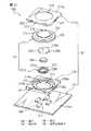
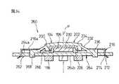
図33及び図34は、上記したポインティングデバイス240に比べてさらなる低背化を可能にする本発明の第8の実施形態によるポインティングデバイス260を示す。ポインティングデバイス260は、基部の構成以外は、前述した第6実施形態によるポインティングデバイス190と実質的同一の構成を有するので、対応する構成要素には同一の参照符号を付してその説明を省略する。
【0131】
ポインティングデバイス260は、基部262と、基部262に対して任意の水平方向へ変位可能に基部262上に支持される操作部194と、操作部194に設置される磁石196と、磁石196の近傍で基部262に設置される複数の磁電変換素子198とを備える。基部262は、図示しないCPU等の電子部品が実装される回路基板264と、操作部194の弾性部202を基部262に固定的に連結するためのカバー部材216とから構成される。したがって基部262は、操作部194の保持部200を摺動自在に支持する支持部材を備えない構成となっている。
【0132】
回路基板264は、その表面264aの所望の円形領域に、操作部194の保持部200を任意の水平方向へ摺動自在に支持する平坦な支持面266を有する。回路基板264はさらに、支持面266を囲繞する方向に円弧状に延びる複数(図では4個)の溝孔268を有する。それら溝孔268は、支持面266を囲繞する同一円周上に互いに分離して配置され、板厚方向へ貫通形成される。隣接する溝孔268の間には、回路基板264の一部分として連結片270が形成される。
【0133】
支持面266の中心を通る複数の溝孔268の中心軸線は、ポインティングデバイス260の中心軸線Pを構成するとともに、支持面266上での保持部200の水平移動範囲の原点位置を規定する。保持部200は、そのフランジ部分228の軸線方向端面を、回路基板264上の支持面266に一様に当接した状態で、支持面266上で360°全方位へ摺動しつつ平行移動できる。そして、4個の磁電変換素子198は、支持面266の反対側で回路基板264の裏面264bに、中心軸線Pを中心とした等間隔分散配置で実装される。なお、カバー部材216は、その四辺に延設した延長片220のそれぞれに、取付孔222(図27)の代わりに差込片272を有し、それら差込片272を、回路基板264の対応位置に貫通形成したスリット274に挿入して適宜折曲することにより、回路基板264に固定される。
【0134】
回路基板264の複数の溝孔268には、弾性部202の第2連結部分236が挿入される。すなわち、弾性部202の第2連結部分236は、その肉厚部分で、回路基板264の複数の溝孔268とカバー部材216の端板部分216aとの間に固定的に挟持かつ掛止される。したがって、弾性部202の第2連結部分236には、回路基板264の複数の連結片270に対応する位置に、連結片270を受容する切欠き236aが形成される。弾性部202の第1及び第2連結部分234、236は、基部262上で保持部200が水平移動する間に実質的に変形することなく、弾性部202を保持部200及び基部262にそれぞれ固定的に連結する。
【0135】
ポインティングデバイス260は、前述したポインティングデバイス190、240と同様にして、基部262上で操作部194を水平移動操作することにより、アナログデータを入力することができる。特にポインティングデバイス260では、支持部材206、244を省略して、基部262の回路基板264の表面264aに直接、支持面266を形成して操作部194の保持部200を搭載する構成としたから、前述したポインティングデバイス190、240に比べて、高さ方向の寸法を一層効果的に削減することができる。
【0136】
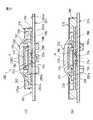
図35〜図37は、低背型でかつクリック機能を有する本発明の第9の実施形態によるポインティングデバイス280を示す。ポインティングデバイス280は、基部の回路基板に連結される支持部材の構成と、クリック機能を付加するためのスイッチ機構を内蔵した構成以外は、前述した第6実施形態によるポインティングデバイス190と実質的同一の構成を有するので、対応する構成要素には同一の参照符号を付してその説明を省略する。なおポインティングデバイス280は、前述した第3実施形態によるポインティングデバイス80と機能的に実質的同一の基本構造を有するものである。
【0137】
ポインティングデバイス280は、基部282と、基部282に対して任意の水平方向へ変位可能に基部282上に支持される操作部194と、操作部194に設置される磁石196と、磁石196の近傍で基部282に設置される複数の磁電変換素子198と、基部282と操作部194との間に配置されるスイッチ機構284とを備える。基部282は、図示しないCPU等の電子部品が実装される回路基板204と、回路基板204に固定的に連結される支持部材286と、支持部材286の外縁領域286aを実質的に遮蔽して支持部材286に固定的に連結されるカバー部材216とを備える。
【0138】
支持部材286は、平面視で略正方形の板状部材であり、その中央の略円形の凹状領域に、操作部194の保持部200を任意の水平方向へ摺動自在に支持する支持部分として機能する複数(図では4個)の弾性梁部分288を、回路基板204の表面204aから離隔した位置に備える。支持部材286のそれら弾性梁部分288には、回路基板204から離れた側に、無負荷状態で回路基板204の表面204aに実質的平行に広がる平坦な支持面288aがそれぞれ形成される。それら支持面288aは互いに協働して、回路基板204の表面204aから突出した位置で、保持部200を任意の水平方向へ摺動自在に支持する。
【0139】
支持部材286の複数の弾性梁部分288は、ポインティングデバイス280の中心軸線Pを中心として放射状に配置され、それらの径方向外端を支点として、互いに独立して弾性的に変位できる。特にこの実施形態では、各弾性梁部分288を、支持部材286の平面視で略正方形輪郭の各頂点部位から径方向へ延設したので、小型化かつ薄型化した支持部材286において、弾性梁部分288の長さを最大限に確保できる。その結果、弾性梁部分288の弾性力の増加及びスイッチ作動時の押下操作力の軽減を図ることができる。
【0140】
支持部材286にはさらに、隣り合う弾性梁部分288の間にそれぞれ扇形に広がる取付部分290が形成される。それら取付部分290の径方向内縁には、各弾性梁部分288の支持面288aを囲繞するようにして、操作部194の保持部200の水平移動範囲を規定する円弧壁292が突設される。各円弧壁292は、回路基板204の表面204aからの高さが各支持面288aよりも高い位置まで突設され、後述するように弾性部202が第2連結部分236で全ての円弧壁292を包囲して支持部材286に取り付けられる。それら円弧壁292は、中心軸線Pを中心とする同一円周上に配置され、中心軸線Pが、複数の支持面288a上での保持部200の水平移動範囲の原点位置を規定する。保持部200は、そのフランジ部分228の軸線方向端面を、複数の弾性梁部分288の支持面288aに一様に当接した状態で、それら支持面288a上で360°全方位へ摺動しつつ平行移動できる。
【0141】
また、複数の弾性梁部分288のうちで所望の1つの弾性梁部分288には、その径方向内端の自由端に、支持面288aの反対側に局部的に隆起する押圧点294が形成される。押圧点294を有する弾性梁部分288は、他の弾性梁部分288よりも若干長く、ポインティングデバイス280の中心軸線Pを越える位置まで延設される。それにより押圧点294は、ポインティングデバイス280の中心軸線P上に整合して配置される。
【0142】
さらに、支持部材286の互いに対向する一対の取付部分290には、円弧壁292の反対側に位置決めピン296が突設される。支持部材286は、それら位置決めピン296を、回路基板204の対応位置に設けられた穴298に嵌入することにより、回路基板204上の所定位置に固定的に組み付けられる。なお、カバー部材216は、支持部材286の四辺に沿って側方へ突設された複数の爪300を、各延長片220の対応の取付孔222にスナップ式に嵌着することにより、支持部材286に固定的に組み付けられる。
【0143】
弾性部202の第2連結部分236は、その肉厚部分で、支持部材286の各円弧壁292の外側環状溝領域292aとカバー部材216の端板部分216aとの間に固定的に挟持かつ掛止される。弾性部202の第1及び第2連結部分234、236は、基部282上で保持部200が水平移動する間に実質的に変形することなく、弾性部202を保持部200及び基部282にそれぞれ固定的に連結する。
【0144】
回路基板204の表面204aには、回路基板204と支持部材286の複数の弾性梁部分288との間に形成される空所の内部で、クリック機能を付加するためのスイッチ機構284が実装される。スイッチ機構284は、可動接点と固定接点とを有する周知の開閉構造を備え、それら両接点がポインティングデバイス280の中心軸線Pに実質的に整合する位置に配置される。すなわち、スイッチ機構284の可動接点は、支持部材286の1つの弾性梁部分288に設けた押圧点294の直下に位置決めされる。そして、4個の磁電変換素子198は、スイッチ機構284の反対側に位置する回路基板204の裏面204bに、中心軸線Pを中心とした等間隔分散配置で実装される。
【0145】
なお、スイッチ機構284の構成は任意であり、可動接点がばねに担持されるメカニカルスイッチや、一対のフレキシブル回路基板を有するメンブレンスイッチ等、様々なものを採用できる。また、スイッチ機構284の外形寸法によっては、複数の磁電変換素子198を、回路基板204と複数の弾性梁部分288との間の空所内に設置することもできる。
【0146】
上記構成を有するポインティングデバイス280では、図37に示す原点位置において、オペレータが操作部194の操作面238を例えば指先で押下して、保持部200のフランジ部分228を複数の弾性梁部分288に押し付けることにより、それら弾性梁部分288の下方に位置するスイッチ機構284を閉成させることができる。この実施形態では、操作部194を押下することにより、各弾性梁部分288が径方向外端を支点に弾性的に撓み、長尺の弾性梁部分288に設けた押圧点294がその直下のスイッチ機構284を押圧して作動させる。
【0147】
このように、ポインティングデバイス280は、前述したポインティングデバイス80における基部82及び操作部14と機能的に同一の基部282及び操作部194を備えるので、ポインティングデバイス80と同様の操作により、操作部194の移動方向及び移動距離に対応したアナログ情報を入力できるとともに、例えば搭載対象機器のディスプレイ上のポインタに関連してクリック操作を実施することができる。しかも、基部282及び操作部194を構成する各構成要素を薄型化したから、ポインティングデバイス80に比べて、全体として低背化を実現したポインティングデバイス280が提供される。
【0148】
図38〜図40は、ポインティングデバイス280に比べてさらなる低背化を可能にする本発明の第10の実施形態によるポインティングデバイス310を示す。ポインティングデバイス310は、基部の回路基板に連結される支持部材の構成以外は、前述した第9実施形態によるポインティングデバイス280と実質的同一の構成を有するので、対応する構成要素には同一の参照符号を付してその説明を省略する。
【0149】
ポインティングデバイス310は、基部312と、基部312に対して任意の水平方向へ変位可能に基部312上に支持される操作部194と、操作部194に設置される磁石196と、磁石196の近傍で基部312に設置される複数の磁電変換素子198とを備える。基部312は、図示しないCPU等の電子部品が実装される回路基板204と、回路基板204に固定的に連結される支持部材314と、支持部材314の外縁領域314aを実質的に遮蔽して支持部材314に固定的に連結されるカバー部材216とから構成される。
【0150】
支持部材314は、平面視で略正方形の板状部材であり、その中央の略円形の凹状領域に、操作部194の保持部200を任意の水平方向へ摺動自在に支持する支持部分として機能する複数(図では4個)の弾性梁部分316を、回路基板204の表面204aから離隔した位置に備える。支持部材314のそれら弾性梁部分316には、回路基板204から離れた側に、無負荷状態で回路基板204の表面204aに実質的平行に広がる平坦な支持面316aがそれぞれ形成される。それら支持面316aは互いに協働して、回路基板204の表面204aから突出した位置で、保持部200を任意の水平方向へ摺動自在に支持する。
【0151】
支持部材314の複数の弾性梁部分316は、ポインティングデバイス310の中心軸線Pを中心として放射状に配置され、それらの径方向外端を支点として、互いに独立して弾性的に変位できる。特にこの実施形態では、各弾性梁部分316を、支持部材314の平面視で略正方形輪郭の各頂点部位から径方向へ延設したので、小型化かつ薄型化した支持部材314において、弾性梁部分316の長さを最大限に確保できる。その結果、弾性梁部分316の弾性力の増加及びスイッチ作動時の押下操作力の軽減を図ることができる。また、この実施形態では、全ての弾性梁部分316が同一の長さを有し、中心軸線Pの周囲に対称に配置される。
【0152】
支持部材314にはさらに、隣り合う弾性梁部分316の間にそれぞれ扇形に広がる取付部分318が形成される。それら取付部分318の径方向外縁には、各弾性梁部分316の支持面316aを囲繞する方向に円弧状に延びる複数(図では4個)の溝320が凹設される。各溝320は、回路基板204の表面204aからの高さが支持面316aよりも低い位置まで凹設される。それら溝320は、中心軸線Pを中心とする同一円周上に配置され、中心軸線Pが、複数の支持面316a上での保持部200の水平移動範囲の原点位置を規定する。保持部200は、そのフランジ部分228の軸線方向端面を、複数の弾性梁部分316の支持面316aに一様に当接した状態で、それら支持面316a上で360°全方位へ摺動しつつ平行移動できる。
【0153】
また、複数の弾性梁部分316のうちで所望の1つの弾性梁部分316には、その径方向内端の自由端に、支持面316aの反対側に局部的に隆起する押圧点322が形成される。押圧点322は、ポインティングデバイス310の中心軸線Pから径方向へずれた位置に配置される。そして、回路基板204の表面204aに実装されるスイッチ機構284は、支持部材314の1つの弾性梁部分316に設けた押圧点322の直下に位置決めされる。
【0154】
さらに、支持部材314の互いに対向する一対の取付部分318には、溝320の反対側に位置決めピン324が突設される。支持部材314は、それら位置決めピン324を、回路基板204の対応位置に設けられた穴298に嵌入することにより、回路基板204上の所定位置に固定的に組み付けられる。なお、カバー部材216は、支持部材314の四辺に沿って側方へ突設された複数の爪326を、各延長片220の対応の取付孔222にスナップ式に嵌着することにより、支持部材314に固定的に組み付けられる。
【0155】
支持部材314の複数の溝320には、弾性部202の第2連結部分236が挿入される。すなわち、弾性部202の第2連結部分236は、その肉厚部分で、支持部材314の複数の溝320とカバー部材216の端板部分216aとの間に固定的に挟持かつ掛止される。したがって、弾性部202の第2連結部分236には、支持部材314の複数の弾性梁部分316に対応する位置に、弾性梁部分316の一部分を受容する切欠き236aが形成される。弾性部202の第1及び第2連結部分234、236は、基部312上で保持部200が水平移動する間に実質的に変形することなく、弾性部202を保持部200及び基部312にそれぞれ固定的に連結する。
【0156】
上記構成を有するポインティングデバイス310は、前述したポインティングデバイス280と同様にして、基部312上で操作部194を水平移動操作することによりアナログデータを入力できるとともに、操作部194を押下操作することにより例えば搭載対象機器のディスプレイ上のポインタに関連してクリック操作を実施することができる。特にポインティングデバイス310では、基部312を構成する支持部材314に、ポインティングデバイス280で支持部材286に設けた複数の円弧壁290の代わりに、支持面316aよりも低い位置まで凹設される複数の溝320を形成し、これら溝320に第2連結部分236を挿入して弾性部202を支持部材314に取り付ける構成としたから、支持部材314のさらなる薄型化が可能となる。したがってポインティングデバイス310では、前述したポインティングデバイス280に比べて、高さ方向の寸法を一層効果的に削減することができる。
【0157】
なお、ポインティングデバイス310においては、図39に示すように、支持部材314の各弾性梁部分316及び各取付部分318に、支持面316a上での操作部194の保持部200の水平移動範囲を規定する円弧状のリブ328を突設することもできる。これらのリブ328は、弾性部202の固定には関与しないので、支持面316aからの突出高さを可及的に削減でき、したがって支持部材314の薄型化を妨げないものである。
【0158】
さらに、ポインティングデバイス310では、支持部材314に設けた複数の弾性梁部分316を、全て同一の寸法及び形状に形成して中心軸線Pの周囲に対象に配置したので、オペレータが操作部194に押下力を加えたときの弾性梁部分316からの反発力が平衡し、結果として正確なスイッチ押下操作を遂行可能とする利点が得られる。特に、図41に示すように、スイッチ機構284を押圧するための押圧点322を、1つの弾性梁部分316上で、水平移動範囲の原点位置にある保持部200のフランジ部分228に重畳する位置に配置すれば、操作部194の保持部200から複数の弾性梁部分316に加えられる押下力を、無駄なくスイッチ機構284に伝達することができる。その結果、オペレータによる押下操作力が軽減され、スイッチ操作性が向上する。
【0159】
上記のように押圧点322をポインティングデバイス310の中心軸線Pからずれた位置に配置する構成では、支持部材314と回路基板204との間に、組立時に互いに合致させるべき方向性が生じる。したがって、図42に示すように、互いに対向する一対の弾性梁部分316に押圧点322を設けたり(図42(a))、全ての弾性梁部分316に押圧点322を設けたり(図42(b))することが、組立作業性を向上させる観点で有利である。
【0160】
クリック機能を有する上記したポインティングデバイス280、310においては、操作部194を押下操作する際に、操作部194を基部282、312及びスイッチ機構284に対して正確に鉛直方向(すなわち操作部194の水平移動方向に略直交する方向)へ変位させることが、カーソル移動データ等のアナログデータの意図しない入力を回避する点で肝要である。そこで、ポインティングデバイス280、310に、操作部194をスイッチ機構284に対して鉛直方向に案内する案内部分を設けることが有利である。
【0161】
図43及び図44は、そのような案内部分を有したポインティングデバイス310の変形例を示す。この変形例では、支持部材314に設けた複数の取付部分318の各々に、径方向内方へ扇形に延長される案内部分330が一体的に形成される。それら案内部分330は、それぞれの内周縁330aが、保持部200のフランジ部分228の外径寸法よりも僅かに大きな直径の、ポインティングデバイス310の中心軸線Pを中心とした同一円周上に配置される。また、各案内部分330の表面330bは、無負荷時の弾性梁部分316の支持面316aと同一の平面上に配置され、複数の支持面316aと協働して、保持部200を任意の水平方向へ摺動自在に支持する。
【0162】
このような構成によると、保持部200が水平移動範囲の原点位置にあるときに操作部194を押下操作すれば、保持部200のフランジ部分228が支持部材314の複数の案内部分330によってスイッチ機構284に対し鉛直方向へ正確に案内される。この間、磁石196と複数の磁電変換素子198との間に水平方向への相対移動は生じないので、カーソル移動データ等のアナログデータの意図しない入力が回避される。また、保持部200が水平移動範囲の原点位置から移動している間は、操作部194に押下力を負荷しても、保持部200のフランジ部分228が支持部材314の案内部分330に干渉するので、弾性梁部分316を押し下げることができない。したがってこの構成によれば、クリック操作等を行う際のスイッチ操作位置を、保持部200の水平移動範囲の原点位置のみに特定することができる。
【0163】
ところで、前述した本発明の種々の実施形態による磁電変換素子型のポインティングデバイスを、携帯電話等の携帯型情報機器に搭載する場合、小型化されたポインティングデバイスの各種構成部品の取り扱いが煩雑になり、情報機器全体の組立作業性が悪化することが懸念される。図45〜図55は、本発明に係るポインティングデバイスを搭載した携帯型情報機器であって、それ自体の組立作業性を向上させる構造を有する本発明の種々の実施形態による携帯型情報機器の主要部を示す。
【0164】
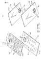
図45は、本発明の一実施形態による携帯型情報機器(例えば携帯電話)の構成部品である回路基板340及びキーパネル342を示す。この携帯型情報機器は、前述した第8実施形態によるポインティングデバイス260を、組立作業性を向上させる構造の下で搭載したものであり、対応する構成要素には同一の参照符号を付してその説明を省略する。
【0165】
図45(a)に示すように、回路基板340は、その表面340aに、携帯型情報機器の主入力部である複数のスイッチ344を、所定の整列配置で搭載して備えている。さらに回路基板340には、表面340aの所定位置に、ポインティングデバイス260の弾性部202を取り付けるための複数(図で4個)の円弧状の溝孔346が形成される。各溝孔346は、図33に示す回路基板264の溝孔268に対応し、それら溝孔346に囲繞される円形領域に、操作部194の保持部200を任意の水平方向へ摺動自在に支持する平坦な支持面266が画定される。回路基板340の裏面340bには、支持面266に対応する位置に、4個の磁電変換素子198が、ポインティングデバイス260の中心軸線Pを中心とした等間隔分散配置で実装される(図45(b))。
【0166】
キーパネル342は、例えばゴム等の弾性材料から一体成形された薄板状部材であり、その表面342aには、回路基板340の複数のスイッチ344に対応する位置に複数のキートップ348が突設される。さらにキーパネル342には、回路基板340の支持面266に対応する位置に、ポインティングデバイス260の弾性部202が一体的に形成される。つまり、弾性部202は、その第2連結部分236で、複数のキートップ348を有するキーパネル342に一体に連結される。そして、弾性部202の主部分232及び第1連結部分234が、キーパネル342の表面342aに突設されるとともに、第2連結部分236の複数の肉厚部分236bが、キーパネル342の裏面342bに突設される。
【0167】
図46(a)に示すように、キーパネル342に形成した弾性部202には、磁石196を収容した保持部200及び保持部200に取り付けられたヨーク230が、第1連結部分234の裏側の凹所に固定的に受容される。この状態でキーパネル342は、その裏面342bを回路基板340の表面340aに接触させて、各キートップ348と各スイッチ344とが整合する所定の相対位置関係で回路基板340に組み付けられる。このとき、弾性部202の第2連結部分236に形成した複数の肉厚部分236bが、回路基板340の対応の溝孔346にそれぞれ嵌入される。それにより保持部200は、回路基板340の支持面266上に適正に位置決めして摺動可能に載置される。さらに、回路基板340に組み付けられたキーパネル342に、携帯型情報機器の筐体350を被せることにより、弾性部202の第2連結部分236が、回路基板340と筐体350との間に固定的に挟持かつ掛止される(図46(b))。このようにして、携帯型情報機器に一体的に組み込まれたポインティングデバイス260が完成する。
【0168】
上記構成によれば、ポインティングデバイス260の本来の構成要素である弾性部202と回路基板264とを、ポインティングデバイス260を搭載する携帯型情報機器の必須の構成要素であるキーパネル342と回路基板340とに、それぞれ一体化したから、ポインティングデバイス260自体の独立した構成部品の点数が削減される。しかも、ポインティングデバイス260を組み立てる際に、携帯型情報機器の主要部品を装備した大判のキーパネル342及び回路基板340に対して、他の小寸の構成部品群を組み合わせていくことができるので、ポインティングデバイス260自体の組立作業性、及びポインティングデバイス260を搭載した携帯型情報機器の組立作業性が、著しく向上する。
【0169】
上記した携帯型情報機器は、回路基板340とキーパネル342とを組み合わせた後に筐体350を取り付ける構成となっているが、先にキーパネルに筐体を取り付け、次いでキーパネルを回路基板に組み付ける手順が採られる場合がある。図47は、このような手順に対応できる変形例としてのキーパネル342及び筐体350を示す。
【0170】
この変形例では、キーパネル342に一体成形された弾性部202は、その第2連結部分236の肉厚部分236bを、キーパネル342の表面342aに突設して備えている(図47(a))。これに対応して、筐体350の裏面350aには、弾性部202を挿入する開口部352の周囲に、第2連結部分236の肉厚部分236bをそれぞれに受容する複数の溝354が形成される(図47(b))。そこで、キーパネル342を、弾性部202及び複数のキートップ348を筐体350に設けた開口部352及び複数のキー孔356にそれぞれ挿入しつつ、筐体350に組み付ける。このとき、弾性部202の第2連結部分236に形成した複数の肉厚部分236bが、筐体350の対応の溝354にそれぞれ嵌入される。
【0171】
このようにして筐体350を取り付けたキーパネル342は、弾性部202に磁石196、保持部200及びヨーク230を受容した状態で、その裏面342bを回路基板340の表面340aに接触させて、各キートップ348と各スイッチ344とが整合する所定の相対位置関係で回路基板340に組み付けられる。それにより、保持部200は、回路基板340の支持面266上に適正に位置決めして摺動可能に載置され、弾性部202の第2連結部分236は、回路基板340と筐体350との間に固定的に挟持かつ掛止される(図48)。このようにして、携帯型情報機器に一体的に組み込まれたポインティングデバイス260が完成する。
【0172】
図49〜図51は、本発明の他の実施形態による携帯型情報機器(例えば携帯電話)の構成部品である回路基板360、キーパネル362及び筐体364を示す。この携帯型情報機器は、前述した第1実施形態によるポインティングデバイス10に類似した構成を有するポインティングデバイス366を、組立作業性を向上させる構造の下で搭載したものであり、ポインティングデバイス10に対応する構成要素には同一の参照符号を付してその説明を省略する。
【0173】
図49に示すように、回路基板360は、その表面360aに、携帯型情報機器の主入力部である複数のスイッチ368を、所定の整列配置で搭載して備えている。また、キーパネル362は、例えばゴム等の弾性材料から一体成形された薄板状部材であり、その表面362aには、回路基板360の複数のスイッチ368に対応する位置に複数のキートップ370が突設される。
【0174】
筐体364は、樹脂材料から一体成形された薄板状部材であり、キーパネル362の複数のキートップ370に対応する位置に複数のキー孔372が貫通形成される。さらに筐体364には、その表面364aの所定位置に凹状領域が設けられ、この凹状領域の底部に、ポインティングデバイス366の支持部材26が一体的に形成される。つまり、支持部材26は、その円筒壁30の外側領域にて、複数のキー孔372を有する筐体364に一体に連結される。そして、支持部材26の支持面28a及び円筒壁30が、筐体364の表面364a側に配置される。
【0175】
図50及び図51に示すように、筐体364に形成した支持部材26には、磁石16を収容した保持部20及び保持部20に取り付けられた弾性部22が、保持部20の軸線方向端縁を支持面28a上に摺動可能に載置した状態で搭載される。さらに、弾性部22の第2連結部分54を覆うようにして、環状のカバー部材36を筐体364に取り付けることにより、弾性部22の第2連結部分54が、筐体364上で固定的に掛止される。
【0176】
この状態で、回路基板360、キーパネル362及び筐体364を、それぞれのスイッチ368、キートップ370及びキー孔372が互いに整合する所定の相対位置関係で相互に組み付ける。このとき、キーパネル362は、筐体364に形成した支持部材26に重畳しない輪郭形状を有し、また回路基板360の裏面360bには、支持部材26の支持面28aに対応する位置に、4個の磁電変換素子18が、ポインティングデバイス366の中心軸線Pを中心とした等間隔分散配置で実装されている。このようにして、携帯型情報機器に一体的に組み込まれたポインティングデバイス366が完成する。
【0177】
上記構成によれば、ポインティングデバイス366の本来の構成要素である支持部材26と回路基板24とを、ポインティングデバイス366を搭載する携帯型情報機器の必須の構成要素である筐体364と回路基板360とに、それぞれ一体化したから、ポインティングデバイス366自体の独立した構成部品の点数が削減される。しかも、ポインティングデバイス366を組み立てる際に、携帯型情報機器の主要部品を装備した大判の筐体364及び回路基板360に対して、他の小寸の構成部品群を組み合わせていくことができるので、ポインティングデバイス366自体の組立作業性、及びポインティングデバイス366を搭載した携帯型情報機器の組立作業性が、著しく向上する。
【0178】
さらに上記構成では、図51に示すように、回路基板360の表面360aと筐体364に形成した支持部材26との間に空間を形成することができるので、回路基板360上の電子部品の実装可能領域が拡大される利点がある。なお、上記構成において、ポインティングデバイス366にクリック機能を有するスイッチ機構を付加する場合は、支持部材26の代わりに、図52に示すように、前述したポインティングデバイス310における複数の弾性梁部分316を有する支持部材314を、筐体364に一体成形すればよい。
【0179】
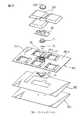
図53〜図55は、本発明のさらに他の実施形態による携帯型情報機器(例えば携帯型キーボード)の構成部品である下部パネル380、メンブレンシート382、スイッチパネル384及びキートップ386を示す。この携帯型情報機器は、前述した第1実施形態によるポインティングデバイス10に類似した構成を有するポインティングデバイス388を、組立作業性を向上させる構造の下で搭載したものであり、ポインティングデバイス10に対応する構成要素には同一の参照符号を付してその説明を省略する。
【0180】
図53に示すように、スイッチパネル384は、樹脂材料から一体成形された薄板状部材であり、メンブレンシート382に形成された複数のスイッチ(図示せず)に対応する位置に複数の開口部390が貫通形成される。さらにスイッチパネル384には、その表面384aの所定位置に凸状領域が設けられ、この凸状領域の底部に、ポインティングデバイス388の支持部材26が一体的に形成される。つまり、支持部材26は、その円筒壁30の外側領域にて、複数の開口部390を有するスイッチパネル384に一体に連結される。そして、支持部材26の支持面28a及び円筒壁30が、スイッチパネル384の表面384a側に配置される。
【0181】
図54及び図55に示すように、スイッチパネル384に形成した支持部材26には、磁石16を収容した保持部20及び保持部20に取り付けられた弾性部22が、保持部20の軸線方向端縁を支持面28a上に摺動可能に載置した状態で搭載される。さらに、弾性部22の第2連結部分54を覆うようにして、カバー部材36をスイッチパネル384に取り付けることにより、弾性部22の第2連結部分54が、スイッチパネル384上で固定的に掛止される。
【0182】
この状態で、メンブレンシート382とスイッチパネル384とを、それぞれのスイッチと開口部390とが互いに整合する所定の相対位置関係で相互に組み付けて、下部パネル380上に載置する。このとき、メンブレンシート382とスイッチパネル384との間には、磁電変換素子18を実装した回路基板24が、支持部材26の支持面28aの反対側に形成される空間に磁電変換素子18を挿入した状態で配置されている。さらに、スイッチパネル384の各開口部390に設置されるスイッチ作動機構(図示せず)に対応のキートップ386を組み付けるとともに、ポインティングデバイス388の弾性部22にキートップ392を取り付ける。このようにして、携帯型情報機器に一体的に組み込まれたポインティングデバイス388が完成する。
【0183】
上記構成においても、ポインティングデバイス388の本来の構成要素である支持部材26を、ポインティングデバイス388を搭載する携帯型情報機器の必須の構成要素であるスイッチパネル384に一体化したから、ポインティングデバイス388自体の独立した構成部品の点数が削減されるとともに、ポインティングデバイス388自体の組立作業性、及びポインティングデバイス388を搭載した携帯型情報機器の組立作業性が、著しく向上する。
【0184】
ところで、前述したクリック機能を有する本発明の種々の実施形態によるポインティングデバイス80、100、280、310は、操作部14、194を、基部82、102、282、312に対して鉛直方向へ押下操作することにより、スイッチ機構84、284を作動させるように構成される。この構成では、操作部14、194の押下操作に伴って、保持部20、200に保持された磁石16、196が基部82、102、282、312上の複数の磁電変換素子18、198に対して必然的に移動する。このときの磁石16、196の移動方向が、複数の磁電変換素子18、198に対して水平方向成分を含んでいる場合には、クリック操作の直前に、それら磁電変換素子18、198の出力電圧の変動により、カーソル移動データ等のアナログデータの信号がポインティングデバイス80、100、280、310から出力されてしまう懸念がある。そこで、適正なクリック操作を実施するためには、操作部14、194を基部82、102、282、312に対して正確に鉛直方向へ押し込むことが必要となり、そのための案内構造を追加装備するか、さもなければオペレータの熟練が要求されることになる。
【0185】
これに対し、図56〜図58に示す本発明の第11の実施形態によるポインティングデバイス400は、低背型でかつ適正なクリック操作を極めて容易に実施できる構造を有する。ポインティングデバイス400は、基部402と、基部402に対して任意の水平方向へ変位可能に基部402上に支持される操作部404と、操作部404に設置される円環状の磁石(例えば永久磁石)406と、磁石406の近傍で基部402に設置される複数の磁電変換素子(例えばホール素子)408と、基部402と操作部404との間に配置されるスイッチ機構410とを備える。操作部404は、磁石406を固定的に保持して基部402上に水平方向へ移動可能に支持される保持部412と、保持部412に連結され、基部402上での保持部412の水平移動に伴い、保持部412を水平移動範囲の原点位置に復帰させる弾性力を発揮する弾性部414と、保持部412から独立して、基部402上に、水平方向に略直交する鉛直方向へ移動可能に配置される作動部416とを備えて構成される。
【0186】
基部402は、図示しないCPU等の電子部品が実装される回路基板418と、回路基板418に固定的に連結される支持部材420とを備える。支持部材420は、平面視で略正方形の板状部材であり、その中央の略円形の凹状領域に、操作部404の保持部412を任意の水平方向へ摺動自在に支持する円環状の支持部分422を有するとともに、支持部分422の中心に形成される円形の開口424にスイッチ機構410を挿入した状態で、回路基板418の表面418aに隙間を介さずに搭載される。なお、この実施形態において「水平方向」とは、回路基板418の略平坦な表面418aに実質的平行な方向を意味する。したがって支持部材420の支持部分422には、回路基板418から離れた側に、回路基板418の表面418aに実質的平行に広がる平坦かつ円環状の支持面422aが形成される。支持面422aは、回路基板418の表面418aから突出した位置で、保持部412を任意の水平方向へ摺動自在に支持する。
【0187】
支持部材420にはさらに、支持面422aを囲繞するようにして、操作部404の保持部412の水平移動範囲を規定する円筒壁426が突設される。円筒壁426は、回路基板418の表面418aからの高さが支持面422aよりも高い位置まで突設され、後述するように弾性部414がその一部分で円筒壁426を包囲して支持部材420に取り付けられる。開口424の中心を通る円筒壁426の中心軸線は、ポインティングデバイス400の中心軸線Pを構成するとともに、支持面422a上での保持部412の水平移動範囲の原点位置を規定する。支持部材420は、例えば接着剤を用いて、回路基板418上の所定位置に固定的に組み付けられる。
【0188】
回路基板418の表面418aには、平面視で略円形輪郭を有するスイッチ機構410が、中心軸線Pを中心として搭載される。また、回路基板418の裏面418bには、計4個の磁電変換素子408が、中心軸線Pを中心とした等間隔分散配置で実装される。このような磁電変換素子408の配置構成により、ポインティングデバイス400は二次元座標系におけるアナログデータ信号を出力できるようになっている。
【0189】
基部402はさらに、支持部材420の外縁領域420aを実質的に遮蔽して支持部材420に固定的に連結されるカバー部材428を備える。カバー部材428は、支持部材420に対応する平面視略正方形状を有する薄板状部材であり、その端板部分428aの中央領域に、後述する操作部404の主要操作部分を水平移動可能に挿通させる略円形の中心開口430を有する。カバー部材428の外縁には、四辺に沿ってそれぞれ延長片432が端板部分428aに略直交する方向へ延設され、各延長片432に、板厚方向へ貫通する取付孔434が貫通形成される。カバー部材428は、支持部材420の四辺に沿って側方へ突設された複数の爪436を、それら延長片432の対応の取付孔434に、各延長片432の弾性変形を利用してスナップ式に嵌着することにより、支持部材420に固定的に組み付けられる。カバー部材428は、中心開口430を通して操作部404の主要操作部分を外方に突出させた状態で、操作部404を基部402から脱落しないように保持する。なお、このような構成を有するカバー部材428は、所望の板金材料から作製できる。
【0190】
図示実施形態では、操作部404の保持部412及び弾性部414は、別部材として個別に作製されて、互いに固定的に組み合わされる。保持部412は、操作部404を基部402上で水平移動操作する間に実質的に変形しない程度の剛性を有する円環状の部材からなる。保持部412の軸線方向一端面(図で上端面)には、同心円状に突設された内周壁438と中間壁440との間に、磁石406を収容する環状凹部442が形成される。磁石406は、例えば接着剤を用いたり圧入したりすることにより、保持部412の環状凹部442に固定できる。保持部412は、その軸線方向他端面を、基部402の支持部材420の支持面422aに一様に当接した状態で、支持面422a上で360°全方位へ摺動しつつ平行移動できる。
【0191】
弾性部414は、操作部404を基部402上で水平移動操作する間に比較的容易に弾性変形する椀状の部材からなり、保持部412の周囲に隙間を介して延長される主部分444と、主部分444の一端で保持部412に連結される第1連結部分446と、主部分444の他端で基部402に連結される第2連結部分448とを一体に有する。弾性部414の主部分444は、保持部412を実質的全周に渡って囲繞するとともに、無負荷状態で保持部412に対し同軸に配置される円錐台状又はドーム状の輪郭形状を有する。したがって弾性部414は、その主部分444が、基部402上での保持部412の水平移動に伴い弾性変形するとともに、変形量に対応する弾性力を、保持部412の水平移動方向に関わらず一様に発揮する。
【0192】
弾性部414の第1連結部分446は、円錐台状輪郭の主部分444の小径端から径方向内方へ円環状に一体に延長され、その内側に形成される窪みに、磁石406を保持した保持部412の内周壁438と中間壁440とが固定的に嵌入される。弾性部414の第1連結部分446は、例えば接着剤を用いたり圧入したりすることにより保持部412に固定できる。さらに第1連結部分446は、その中央に、保持部412の内周壁438及び中間壁440に対して同心に貫通形成される円筒状の受容穴450を有する。第1連結部分446は、保持部412及び磁石406の軸線方向一端面を密接被覆して延び、その外面に、オペレータが操作部404を移動操作する際に例えば手の指先を接触させる操作面452が形成される。
【0193】
弾性部414の第2連結部分448は、円錐台状輪郭の主部分444の大径端から径方向及び軸線方向へフランジ状に突出して一体に延長され、その肉厚部分で、基部402を構成する支持部材420の円筒壁426の外側環状溝領域426aとカバー部材428の端板部分428aとの間に固定的に挟持かつ掛止される。第1及び第2連結部分446、448は、基部402上で保持部412が水平移動する間に実質的に変形することなく、弾性部414を保持部412及び基部402にそれぞれ固定的に連結する。
【0194】
なお弾性部414は、合成ゴム、天然ゴム等の種々の弾性材料から形成できる。特に、ポインティングデバイス400を搭載対象機器の主回路基板に実装する際にリフロー工程を実施することを考慮すれば、シリコンゴム等の、高温下でも性質が劣化し難い材料から形成することが有利である。
【0195】
作動部416は、基部402上で鉛直移動操作される間に実質的に変形しない程度の剛性を有する円柱状の部材からなる。作動部416の軸線方向一端(図で下端)には、径方向外方へ突縁部分416aが一体的に延設される。また、作動部416の軸線方向他端には、オペレータが作動部416を押下操作する際に例えば手の指先を接触させる押下操作面454が形成される。作動部416は、弾性部414から分離されて、弾性部414の第1連結部分446に設けた受容穴450に隙間を介して受容される。このとき作動部416は、その突縁部分416aが、保持部412の内周壁438から径方向内方へ僅かに突設された肩部分438aに、磁石406とは反対側で係合できるように方向付けされる。作動部416の突縁部分416aが保持部412の肩部分438aに係合した状態で、作動部416の押下操作面454は、弾性部414の操作面452の中央で僅かに隆起して配置される。
【0196】
作動部416の軸線方向一端面(図で下端面)には、その中央に、局部的に隆起する押圧点456が形成される。押圧点456は、ポインティングデバイス400の中心軸線P上に整合して配置される。操作部404を基部402に適正に組み付けた状態で、作動部416は、その押圧点456を、支持部材420の開口424内に配置されたスイッチ機構410に当接して、操作部404内で鉛直方向へ移動可能に、スイッチ機構410に支持される。
【0197】
なお、スイッチ機構410の構成は任意であり、可動接点がばねに担持されるメカニカルスイッチや、一対のフレキシブル回路基板を有するメンブレンスイッチ等、様々なものを採用できる。また、スイッチ機構410の外形寸法によっては、複数の磁電変換素子408を、支持部材420の開口424内に設置することもできる。
【0198】
上記した各種構成部品を適正に組み合わせた状態で、操作部404は、弾性部414の主部分444及び第1連結部分446並びに作動部416の押下操作面454を含む部分を、基部402のカバー部材428の中心開口430に水平移動可能に挿通するとともに、カバー部材428の端板部分428aから外方に突出した位置に配置する。この状態でオペレータは、弾性部414の第1連結部分446に形成される操作面238を、例えば手指により操作して、保持部412を基部402上で水平移動させることができるとともに、作動部416の押下操作面454を、例えば手指により押下操作して、作動部416を基部402上で鉛直移動させることができる。
【0199】
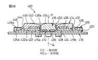
図58に示すように、操作部404の弾性部414が平衡状態にあるときには、保持部412及びその環状凹部442に保持される磁石406並びに作動部416の中心軸線Qは、ポインティングデバイス400の中心軸線Pに合致する。この状態で保持部412は、基部402の支持部材420上で水平移動範囲の原点位置に位置決めされ、回路基板418上の4個の磁電変換素子408が磁石406から等距離の位置に配置される。この状態から、オペレータが操作面452に指先を当接して保持部412を任意の水平方向へ平行移動させると、弾性部414の主部分444が、保持部412の移動方向及び移動距離に対応して、全周に渡り異なる形態の弾性変形を生じる(図59(a))。それにより弾性部414は、主部分444の全体で合力としての弾性力を発揮し、保持部412をその移動方向と反対の方向に付勢する。したがってオペレータは、弾性部414の主部分444が生ずるばね付勢力に抗して、操作部404を水平移動操作することになる。
【0200】
また、図58に示す原点位置において、オペレータが操作部404の作動部416の押下操作面454を例えば指先で押下して、作動部416の押圧点456をスイッチ機構410に押し付けることにより、スイッチ機構284を閉成させることができる(図59(b))。このとき、保持部412は、支持部材420の支持面422a上に静止支持されているので、オペレータの押下操作力が弾性部414の操作面452に負荷されたとしても、保持部412すなわち磁石406の鉛直方向移動は確実に回避される。
【0201】
このように、ポインティングデバイス400では、操作部404に実質的水平方向への操作力を負荷することにより、保持部412の移動方向及び移動距離に対応したアナログ情報を入力できるとともに、原点位置にある操作部404に実質的鉛直方向への押下操作力を負荷することにより、例えば搭載対象機器のディスプレイ上のポインタに関連してクリック操作を実施することができる。しかも押下操作時には、基部402に対する保持部412の鉛直方向移動を確実に防止できるので、磁石406と複数の磁電変換素子408との相対移動が排除される。したがってポインティングデバイス400では、適正なクリック操作を極めて容易に実施できる。
【0202】
また、ポインティングデバイス400では、前述した第9実施形態によるポインティングデバイス280と同様に、基部402及び操作部404を構成する各構成要素を薄型化したから、全体として低背化を実現することができる。なお、第10実施形態によるポインティングデバイス310と同様に、支持部材420に、弾性部414の第2連結部分448を取り付ける環状の溝を、円筒壁426に代えて形成することにより、さらなる低背化を実現することもできる。
【0203】
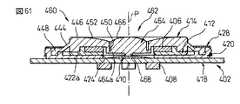
図60及び図61は、低背型でかつ適正なクリック操作を極めて容易に実施できる本発明の第12の実施形態によるポインティングデバイス460を示す。ポインティングデバイス460は、操作部の作動部の構成以外は、前述した第11実施形態によるポインティングデバイス400と実質的同一の構成を有するので、対応する構成要素には同一の参照符号を付してその説明を省略する。
【0204】
ポインティングデバイス460は、基部402と、基部402に対して任意の水平方向へ変位可能に基部402上に支持される操作部462と、操作部462に設置される磁石406と、磁石406の近傍で基部402に設置される複数の磁電変換素子408と、基部402と操作部462との間に配置されるスイッチ機構410とを備える。基部402は、図示しないCPU等の電子部品が実装される回路基板418と、回路基板418に固定的に連結される支持部材420と、支持部材420の外縁領域420aを実質的に遮蔽して支持部材420に固定的に連結されるカバー部材428とを備える。
【0205】
操作部462は、磁石406を保持して基部402上に水平移動可能に支持される保持部412と、保持部412をその水平移動範囲の原点位置に復帰させる弾性部414と、保持部412から独立して、基部402上に、水平方向に略直交する鉛直方向へ移動可能に配置される作動部464とを備えて構成される。作動部464は、弾性部414の第1連結部分446に一体的に連結されて、受容穴450内に収容される。詳述すれば、作動部464は、その軸線方向一端(図で下端)に径方向外方へ延設された突縁部分464aにて、弾性部414の第1連結部分446の受容穴450を画定する内周壁に、例えば弾性部414と同一の材料から一体的に成形される。
【0206】
作動部464の軸線方向他端には、オペレータが作動部464を押下操作する際に例えば手の指先を接触させる押下操作面466が形成される。作動部464に押下力が負荷されない状態では、作動部464の押下操作面466は、弾性部414の操作面452の中央で僅かに隆起して配置される。また、作動部464に押下力が負荷されたときには、弾性部414と作動部464との相互連結領域が弾性変形しつつ、作動部464が弾性部414の受容穴450内で鉛直方向へ移動する。なお、作動部464に押下力が負荷されたときに、弾性部414と作動部464との相互連結領域が障害無く弾性変形できるように、図示のように保持部412の内周壁438(図56)を省略することが望ましい。
【0207】
作動部464の軸線方向一端面(図で下端面)には、その中央に、局部的に隆起する押圧点468が形成される。押圧点468は、ポインティングデバイス460の中心軸線P上に整合して配置される。操作部462を基部402に適正に組み付けた状態で、作動部464は、その押圧点468を、支持部材420の開口424内に配置されたスイッチ機構410に当接して、操作部462内で鉛直方向へ移動可能に、スイッチ機構410に支持される。
【0208】
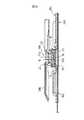
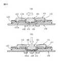
上記構成を有するポインティングデバイス460は、前述したポインティングデバイス400と同様にして、操作部462に実質的水平方向への操作力を負荷することにより、基部402上での保持部412の移動方向及び移動距離に対応したアナログ情報を入力できる(図62(a))。また、図61に示す原点位置において、オペレータが操作部462の作動部464の押下操作面466を例えば指先で押下して、作動部464の押圧点468をスイッチ機構410に押し付けることによりスイッチ機構410を作動させることができる(図62(b))。このとき、基部402に対する保持部412の鉛直方向移動が確実に防止されるので、例えば搭載対象機器のディスプレイ上のポインタに関連して、適正なクリック操作を極めて容易に実施できる。特にポインティングデバイス460では、操作部462の弾性部414と作動部464とを一体化したので、部品点数が削減され、組立作業性が向上する利点が得られる。
【0209】
押下操作専用の作動部416、464を有する上記したポインティングデバイス400、460においては、押下操作時に、作動部416、464を正確に鉛直方向へ移動させることだけでなく、保持部412を支持部材420上で無意識に水平方向へ移動させないようにすることが、カーソル移動データ等のアナログデータの意図しない入力を回避する点で肝要である。そこで、ポインティングデバイス400、460に、作動部416、464をスイッチ機構410の直上の限られた位置でのみ鉛直方向に案内する案内部分を設けることが有利である。
【0210】
図63は、そのような案内部分を有したポインティングデバイス460の変形例を示す。この変形例では、支持部材420に設けた開口424が、作動部464の突縁部分464aの外径寸法よりも僅かに大きな径寸法を有するように形成されている。また、作動部464に押下力を負荷しない状態では、作動部464の底面が支持部材420の支持面422aよりも回路基板418の表面418aから僅かに遠い位置に配置されるように形成されている。
【0211】
このような構成によると、作動部464に押下力を負荷しないようにして操作部462を水平移動操作すれば、作動部464が支持部材420に干渉することなく、保持部412が支持面422a上で所望の水平方向へ円滑に摺動する(図63(a))。保持部412が水平移動している間に、作動部464に押下力を加えたとしても、作動部464が支持部材420の支持面422aに衝突するので、スイッチ機構410を作動させることができない。また、保持部412が水平移動範囲の原点位置にあるときに作動部464を押下操作すれば、作動部464の突縁部分464aが、支持部材420の開口424によってスイッチ機構410の直上で鉛直方向へ正確に案内される(図63(b))。この間、操作部462に無意識に水平方向分力が負荷されたとしても、作動部464が開口424内で支持部材420に衝突するので、保持部412は水平方向へ移動しない。したがってこの構成によれば、クリック操作等を行う際のスイッチ操作位置を、保持部412の水平移動範囲の原点位置のみに特定できるとともに、スイッチ操作時にカーソル移動データ等のアナログデータの意図しない入力を確実に回避できる。
【0212】
また、弾性部414に一体成形した作動部464を有する上記したポインティングデバイス460においては、図64に他の変形例として示すように、作動部464に、弾性部414から独立したキートップ470を装備することができる。この場合、作動部464は、弾性部414に連結される突縁部分464aの近傍領域のみを弾性部414と一体的に成形するとともに、この一体成形部分の、弾性部414の操作面452側に、キートップ470を固定することにより構成できる(図65(a))。そしてキートップ470には、操作面452に近接するその軸線方向端面に、作動部464を鉛直方向へ押圧操作するための押圧操作面472が形成される。
【0213】
この構成によれば、弾性部414とは異なる材料から作製されるキートップ470を装備することにより、作動部464の視認性及び押下操作性、並びに操作部462全体の意匠性を向上させることができる。特に、図示のように、キートップ470の軸線方向他端面の中央に押圧ピン474を突設し、この押圧ピン474を、作動部464の一体成形部分の中央に設けた貫通孔464bに挿通して、その先端を作動部464からスイッチ機構410に向けて突出させることが好ましい。この構成によれば、弾性部414よりも硬質の材料から形成されるキートップ470の押圧ピン474により、スイッチ機構410を正確に作動させることができる。
【0214】
さらに、操作部462の寸法の増加を許容できる場合は、図65(b)に示すように、磁石406の内径寸法よりも大きな外径の押下操作面476を有するキートップ478を、作動部464に装備することもできる。この構成では、作動部464の視認性及び押下操作性を一層向上させることができる。
【0215】
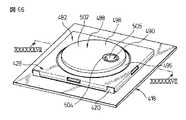
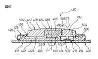
図66及び図67は、押下操作専用の作動部を有する本発明の第13の実施形態によるポインティングデバイス480を示す。ポインティングデバイス480は、操作部の構成以外は、前述した第11実施形態によるポインティングデバイス400と実質的同一の構成を有するので、対応する構成要素には同一の参照符号を付してその説明を省略する。
【0216】
ポインティングデバイス480は、基部402と、基部402に対して任意の水平方向へ変位可能に基部402上に支持される操作部482と、操作部482に設置される磁石484と、磁石484の近傍で基部402に設置される複数の磁電変換素子408と、基部402と操作部482との間に配置されるスイッチ機構410とを備える。基部402は、図示しないCPU等の電子部品が実装される回路基板418と、回路基板418に固定的に連結される支持部材420と、支持部材420の外縁領域420aを実質的に遮蔽して支持部材420に固定的に連結されるカバー部材428とを備える。スイッチ機構410は、回路基板418上でポインティングデバイス480の中心軸線Pからずれた位置に搭載され、支持部材420は、スイッチ機構410に対応する位置に開口424を有する。
【0217】
操作部482は、磁石484を保持して基部402上に水平移動可能に支持される保持部486と、保持部486をその水平移動範囲の原点位置に復帰させる弾性部488と、保持部486から独立して、基部402上に、鉛直方向へ移動可能に配置される作動部490とを備えて構成される。保持部486は、中央に収容溝492を有する板状部材であり、収容溝492に近接する位置に、支持部材420の開口424に対応する寸法の開口494が形成される。保持部486の開口494は、保持部486が基部402上で水平移動範囲の原点位置にあるときに、支持部材420の開口424に整合かつ重畳して配置される。保持部486は、収容溝492に円板状の磁石484を固定的に収容して、弾性部488に取り付けられる。保持部486は、その軸線方向端面を、支持部材420の支持面422aに一様に当接した状態で、支持面422a上で360°全方位へ摺動しつつ平行移動できる。
【0218】
弾性部488は、保持部486の周囲に隙間を介して延長される主部分496と、主部分496の一端で保持部486に連結される第1連結部分498と、主部分496の他端で基部402に連結される第2連結部分500とを一体に有する。弾性部488は、その主部分496が、基部402上での保持部486の水平移動に伴い弾性変形するとともに、変形量に対応する弾性力を、保持部486の水平移動方向に関わらず一様に発揮する。弾性部488の第1連結部分498には、オペレータが操作部482を移動操作する際に例えば手の指先を接触させる操作面502が形成される。さらに第1連結部分498は、保持部486の開口494に対応する位置に、円筒状の受容穴504を有する。
【0219】
作動部490は、軸線方向一端(図で下端)に径方向外方へ延設された突縁部分490aにて、弾性部488の第1連結部分498に一体的に連結されて、受容穴504内に収容される。作動部490の軸線方向他端には、オペレータが作動部490を押下操作する際に例えば手の指先を接触させる押下操作面506が形成される。また、作動部490の軸線方向一端面(図で下端面)には、その中央に、局部的に隆起する押圧点508が形成される。操作部482を基部402に適正に組み付けた状態で、作動部490は、その押圧点508を、支持部材420の開口424内に配置されたスイッチ機構410に当接して、操作部482内で鉛直方向へ移動可能に、スイッチ機構410に支持される。
【0220】
上記構成を有するポインティングデバイス480は、前述したポインティングデバイス460と同様にして、操作部482に実質的水平方向への操作力を負荷することにより、基部402上での保持部486の移動方向及び移動距離に対応したアナログ情報を入力できる。また、図67に示す原点位置において、オペレータが操作部482の作動部490の押下操作面506を例えば指先で押下して、作動部490の押圧点508をスイッチ機構410に押し付けることによりスイッチ機構410を作動させることができる。このとき、基部402に対する保持部486の鉛直方向移動が確実に防止されるので、例えば搭載対象機器のディスプレイ上のポインタに関連して、適正なクリック操作を極めて容易に実施できる。特にポインティングデバイス480では、中心軸線Pからずれた位置に作動部490を配置したので、単純な円板形状の磁石484を使用できる利点が得られる。また、回路基板418上に複数のスイッチ機構410を搭載するとともに、操作部482にそれらスイッチ機構410に対応する複数の作動部490を設けることができるので、多様な機能性をポインティングデバイス480に付加することができる。
【0221】
クリック機能を有する前述した種々の実施形態によるポインティングデバイスでは、操作部の正確な鉛直移動操作を可能にする案内部分を設ける等、構造上の工夫により、スイッチ押下操作時にアナログデータの意図しない入力を回避することができる。しかし、このような案内構造に代えて、又は補足的に追加して、ポインティングデバイスから出力される信号処理上の工夫により、スイッチ押下操作時にアナログデータの意図しない入力を回避することもできる。図68は、そのような工夫を施した本発明の関連技術による信号処理方法を示す。
【0222】
例えば前述した第11実施形態によるポインティングデバイス400において、作動部416を押下操作してスイッチ機構410を作動させると、回路基板418に実装したCPUが、スイッチ機構410から受け取ったオン信号をクリック信号として処理して、ポインティングデバイス400を搭載したデータ処理装置の処理機構に出力する。ここで、図68に示すように、スイッチ機構410がオン状態にある間は、仮に保持部412が水平移動したとしても、CPUがカーソル移動データ信号を出力しないように、信号処理プログラムを設定する。それにより、スイッチ押下操作時に、意図しないアナログデータ入力を回避することができる。
【0223】
さらにポインティングデバイス400では、作動部416の押下操作を解除した後にも、保持部412に無意識の水平移動が生じたときに、カーソル移動データ信号が出力されてしまう場合がある。そこで、図68に示すように、スイッチ機構410がオフ状態になった後に、所定時間Tの間は、仮に保持部412が水平移動したとしても、CPUがカーソル移動データ信号を出力しないように、信号処理プログラムを設定することが有利である。それにより、スイッチ押下操作の解除後にも、意図しないアナログデータ入力を回避することができる。なお、この構成における時間Tは、ポインティングデバイスの操作性を考慮して様々に設定できる。例えば、パーソナルコンピュータ等で多用されるダブルクリック操作の間に、ディスプレイ画面上でポインタを一定位置に容易に保持し得る程度の時間に設定することができる。
【0224】
以上、低背化及び操作性向上を主目的とした幾つかの好適な実施形態を説明したが、それら実施形態においても図示構成以外の様々な形態を採ることができる。例えば、本発明に係る低背型ポインティングデバイスの特徴的構成は、磁石と複数の磁電変換素子との位置関係が、図示実施形態とは逆の構成、すなわち基部に設置した磁石に対し、操作部に設置した磁電変換素子が変位するように構成されたポインティングデバイスにおいても、有効に採用でき、かつ同様に格別の作用効果を奏するものである。また、上記した種々の低背型ポインティングデバイスに、前述したコネクタ付き回路基板の製造方法を適用することもできる。さらに、前述したポインティングデバイスの出力信号処理方法は、図示実施形態による磁電変換素子型のポインティングデバイスへの適用に限らず、他の様々なアナログデータ入力構造を有するポインティングデバイスに適用できるものである。
【0225】
【発明の効果】
以上の説明から明らかなように、本発明によれば、磁電変換素子型のポインティングデバイスにおいて、操作部の操作性を損なうことなく、携帯型情報機器への搭載が実現可能な水準まで外形寸法を削減することが可能になる。また、磁電変換素子型のポインティングデバイスにおいて、搭載対象機器の実装基板への電気的及び機械的接続を狭小な空間で確実かつ安定的に実現することが可能になる。したがって本発明によれば、電子手帳、携帯情報端末(PDA)、携帯電話等の、手持操作可能な種々の携帯型情報機器へ有利に搭載できるポインティングデバイスが提供される。
【0226】
また、本発明によれば、磁電変換素子型のポインティングデバイスを搭載した携帯型情報機器の、組立作業性を向上させることが可能になる。さらに、クリック機能を有する磁電変換素子型のポインティングデバイスにおいて、案内構造を追加装備やオペレータの熟練を要することなく、適正なクリック操作を容易に実施することが可能になる。
【図面の簡単な説明】
【図1】本発明の第1実施形態によるポインティングデバイスの分解斜視図である。
【図2】図1のポインティングデバイスの組立斜視図である。
【図3】図2の線III−IIIに沿ったポインティングデバイスの縦断面図で、操作部が原点位置にある状態を示す。
【図4】図3に対応する縦断面図で、操作部を水平移動させた状態を示す。
【図5】本発明の第2実施形態によるポインティングデバイスの分解斜視図である。
【図6】図5のポインティングデバイスの縦断面図で、操作部が原点位置にある状態を示す。
【図7】本発明の第3実施形態によるポインティングデバイスの分解斜視図である。
【図8】図7のポインティングデバイスの縦断面図で、操作部が原点位置にある状態を示す。
【図9】図8に対応する縦断面図で、操作部を押下操作した状態を示す。
【図10】本発明の第4実施形態によるポインティングデバイスの分解斜視図である。
【図11】図10のポインティングデバイスの縦断面図で、操作部が原点位置にある状態を示す。
【図12】図11に対応する縦断面図で、操作部を押下操作した状態を示す。
【図13】変形例によるポインティングデバイスの縦断面分解図である。
【図14】他の変形例によるポインティングデバイスの縦断面分解図である。
【図15】さらに他の変形例によるポインティングデバイスの縦断面分解図である。
【図16】さらに他の変形例によるポインティングデバイスの分解斜視図である。
【図17】図16のポインティングデバイスの縦断面図で、操作部が原点位置にある状態を示す。
【図18】図17に対応する縦断面図で、操作部を水平移動させた状態を示す。
【図19】さらに他の変形例によるポインティングデバイスの分解斜視図である。
【図20】図19のポインティングデバイスの縦断面図で、操作部が原点位置にある状態を示す。
【図21】本発明の第5実施形態によるポインティングデバイスを、実装基板に実装した状態で示す組立斜視図である。
【図22】図21のポインティングデバイスの分解斜視図である。
【図23】図21のポインティングデバイスにおけるコネクタ付き回路基板の平面図である。
【図24】図23の回路基板の製造工程を説明する図で、コネクタを取り付ける前段階の回路基板の平面図である。
【図25】図24の回路基板の(a)部分拡大断面図、及び(b)部分拡大平面図である。
【図26】図23の線XXVI−XXVIに沿った回路基板の断面図である。
【図27】本発明の第6実施形態によるポインティングデバイスの分解斜視図である。
【図28】図27のポインティングデバイスの組立斜視図である。
【図29】図28の線XXIX−XXIXに沿ったポインティングデバイスの縦断面図で、操作部が原点位置にある状態を示す。
【図30】本発明の第7実施形態によるポインティングデバイスの分解斜視図である。
【図31】図30のポインティングデバイスにおける支持部材の斜視図である。
【図32】図30のポインティングデバイスの縦断面図で、操作部が原点位置にある状態を示す。
【図33】本発明の第8実施形態によるポインティングデバイスの分解斜視図である。
【図34】図33のポインティングデバイスの縦断面図で、操作部が原点位置にある状態を示す。
【図35】本発明の第9実施形態によるポインティングデバイスの分解斜視図である。
【図36】図35のポインティングデバイスにおける支持部材の図で、(a)上方から見た斜視図、及び(b)下方から見た斜視図である。
【図37】図35のポインティングデバイスの縦断面図で、(a)図36の線XXXVIIA−XXXVIIAに沿って示す図、及び(b)図36の線XXXVIIB−XXXVIIBに沿って示す図である。
【図38】本発明の第10実施形態によるポインティングデバイスの分解斜視図である。
【図39】図38のポインティングデバイスにおける支持部材の図で、(a)上方から見た斜視図、及び(b)下方から見た斜視図である。
【図40】図38のポインティングデバイスの縦断面図で、(a)図41の線XXXXA−XXXXAに沿って示す図、及び(b)図36の線XXXXB−XXXXBに沿って示す図である。
【図41】図38のポインティングデバイスの変形例における支持部材の底面図である。
【図42】(a)図38のポインティングデバイスの他の変形例における支持部材の平面図、及び(b)さらに他の変形例における支持部材の平面図である。
【図43】図38のポインティングデバイスの変形例における支持部材の平面図である。
【図44】図43の支持部材を備えた変形例によるポインティングデバイスの縦断面図である。
【図45】本発明の一実施形態による携帯型情報機器の主要構成要素を示す分解斜視図で、(a)上方から見た図、及び(b)下方から見た図である。
【図46】図45の主要構成要素の組立時の縦断面図で、(a)筐体組み付け前、及び(b)筐体組み付け後の状態を示す。
【図47】本発明の他の実施形態による携帯型情報機器の主要構成要素を示す分解斜視図で、(a)上方から見た図、及び(b)下方から見た図である。
【図48】図47の主要構成要素の組立時の縦断面図である。
【図49】本発明のさらに他の実施形態による携帯型情報機器の主要構成要素を示す分解斜視図である。
【図50】図49に示す筐体にポインティングデバイスの構成要素を取り付けた状態を示す斜視図である。
【図51】図49の主要構成要素の組立時の図で、図50の線XXXXXI−XXXXXIに沿って示す縦断面図である。
【図52】図49に示す筐体の変形例の拡大斜視図である。
【図53】本発明のさらに他の実施形態による携帯型情報機器の主要構成要素を示す分解斜視図である。
【図54】図53の主要構成要素の組立時の斜視図である。
【図55】図53の主要構成要素の組立時の図で、図54の線XXXXXV−XXXXXVに沿って示す縦断面図である。
【図56】本発明の第11実施形態によるポインティングデバイスの分解斜視図である。
【図57】図56のポインティングデバイスの組立斜視図である。
【図58】図57の線XXXXXVIII−XXXXXVIIIに沿ったポインティングデバイスの縦断面図で、操作部が原点位置にある状態を示す。
【図59】図56のポインティングデバイスの縦断面図で、(a)水平移動操作時、及び(b)押下操作時の状態を示す。
【図60】本発明の第12実施形態によるポインティングデバイスの分解斜視図である。
【図61】図60のポインティングデバイスの組立斜視図である。
【図62】図60のポインティングデバイスの縦断面図で、(a)水平移動操作時、及び(b)押下操作時の状態を示す。
【図63】図60のポインティングデバイスの変形例の縦断面図で、(a)水平移動操作時、及び(b)押下操作時の状態を示す。
【図64】図60のポインティングデバイスの他の変形例の分解斜視図である。
【図65】(a)図64の変形例の縦断面図、及び(b)他の変形例の縦断面図である。
【図66】本発明の第13実施形態によるポインティングデバイスの組立斜視図である。
【図67】図66のポインティングデバイスの、線XXXXXXVII−XXXXXXVIIに沿った縦断面図である。
【図68】 本発明の関連技術による信号処理方法を示す線図である。
【符号の説明】
10、60、80、100、150、190、240、260、280、310、400、460、480…ポインティングデバイス
12、62、82、102、192、242、262、282、312、402…基部
14、194、404、462、482…操作部
16、196、406、484…磁石
18、198、408…磁電変換素子
20、200、412…保持部
22、202、414、488…弾性部
24、204、418…回路基板
26、64、86、206、244、286、314、420…支持部材
28、208、422…支持部分
28a、70、88a、114a、208a、288a、316a、422a…支持面
36、216、428…カバー部材
50、232、444、496…主部分
52、234、446、498…第1連結部分
54、236、448、500…第2連結部分
58、238、452、502…操作面
84、284、410…スイッチ機構
88、288、316…弾性梁部分
104…第1支持部材
106…弾性部材
108…第2支持部材
122、470、478…キートップ
128…板ばね
134…コイルばね
152…コネクタ
154…絶縁部材
156…端子
158…スルーホール
164、166、176…はんだ
168…取付部材
178…ランド
180…実装領域
182…捨て領域
184…境界線
416、464、490…作動部[0001]
BACKGROUND OF THE INVENTION
The present invention relates to a pointing device incorporated in a data processing apparatus. Furthermore, the present invention relates to a portable information device equipped with a pointing device. Furthermore, the present invention relates to an output signal processing method for a pointing device. Furthermore, the present invention relates to a method for manufacturing a circuit board with a connector provided in an electronic device such as a pointing device.
[0002]
[Prior art]
Auxiliary input that indicates coordinate data such as cursor movement data on the display when the operator manually inputs analog information in a digital data processing device equipped with a display and keyboard, such as a personal computer or word processor An apparatus having a pointing device as an apparatus is well known. In particular, a portable data processing device generally has a configuration in which a pointing device is integrated into a housing of the processing device.
[0003]
As a pointing device of this type, a base, an operation unit supported movably on the base, a magnetoelectric conversion element installed on the base, and a magnet installed on the operation unit in the vicinity of the magnetoelectric conversion element are provided. What to do is known. In this pointing device, the operator moves the operation unit in an arbitrary curved surface direction on the base, thereby changing the relative positional relationship between the magnet and the magnetoelectric conversion element to change the output voltage of the magnetoelectric conversion element. Thus, analog information corresponding to the moving direction and moving distance of the operation unit can be input.
[0004]
In addition to the above-described configuration, a pointing device is also known in which a switch mechanism is provided between the base and the operation unit, and the switch mechanism is operated by the operator pushing the operation unit toward the base ( For example, see Japanese Patent Publication No. 7-117875). In this pointing device, in addition to inputting analog information, a click operation can be performed in association with a pointer on a display of a target device, for example, by pressing the operation unit.
[0005]
[Problems to be solved by the invention]
In general, a magneto-electric conversion element type pointing device requires a small amount of movement of an operation unit necessary for inputting coordinate data and has relatively low power consumption. Therefore, such as an electronic notebook, a personal digital assistant (PDA), a mobile phone, It is considered that it can be particularly advantageously mounted on various portable information devices that can be operated by hand. However, in the above-described conventional magnetoelectric conversion element type pointing device, since the operation part is moved in the curved surface direction on the base part, the required curvature and the mutual engagement part between the base part and the operation part are adopted. It is necessary to form a curved surface having an area, and as a result, it has been difficult to reduce the external dimensions of the pointing device to such an extent that it can be mounted on a portable information device.
[0006]
For example, in a foldable portable information device in which the display unit and the keyboard unit are hinged to each other, it is possible to eliminate the protrusion of the switches installed in the keyboard unit from the surface of the keyboard as much as possible. This is desirable from the viewpoint of reducing the thickness and further improving portability. Therefore, when a magnetoelectric conversion element type pointing device is mounted on the keyboard portion of such a portable information device, it is required to reduce the dimension of the pointing device particularly in the height direction as much as possible.
[0007]
In addition, when a pointing device is mounted on a portable information device, the electrical and mechanical connection between the pointing device and the main circuit board (mounting substrate) of the information device is ensured in the narrow internal space of the device housing. It is required to be realized stably. Furthermore, when a magneto-electric conversion element type pointing device is mounted on a portable information device, handling of various components of the miniaturized pointing device becomes complicated, and there is a concern that the assembly workability of the entire information device may deteriorate. The
[0008]
Further, in a magnetoelectric conversion element type pointing device having a click function, a relative movement inevitably occurs between the magnet and the magnetoelectric conversion element as the operation unit is pressed. At this time, depending on the relative movement directions of the two, there is a concern that an analog data signal such as cursor movement data may be output from the pointing device due to fluctuations in the output voltage of the magnetoelectric transducer immediately before the click operation. Therefore, in order to perform an appropriate click operation, it is necessary to accurately push the operation unit vertically with respect to the base, and an additional guide structure is required for that purpose, or the skill of the operator is required. Will be.
[0009]
Therefore, an object of the present invention is to provide a pointing device that can reduce the outer dimensions to a level that can be mounted on a portable information device without impairing the operability of the operation unit in a magnetoelectric conversion element type pointing device. It is in.
Another object of the present invention is to provide a pointing device capable of reliably and stably realizing an electrical and mechanical connection to a mounting substrate of a mounting target device in a narrow space in a magnetoelectric conversion element type pointing device. is there.
[0010]
Book Still another object of the present invention is to provide a portable information device having a structure that improves assembly workability in a portable information device equipped with a magnetoelectric conversion element type pointing device.
[0011]
Still another object of the present invention is to provide a pointing device of a magnetoelectric transducer type pointing device having a click function, which can easily carry out an appropriate click operation without requiring additional equipment or operator skill.The It is to provide.
[0012]
[Means for Solving the Problems]
In order to achieve the above object, the invention according to
[0014]
Claim2 The invention described in
[0015]
Claim3 The invention described in
[0017]
Claim4 The invention described in claim3 The pointing device according to
[0018]
Claim5 The invention described in claim3 or 4 The pointing device according to
[0019]
[0020]
Claim7 The invention described in
[0021]
[0022]
[0024]
[0025]
[0026]
[0029]
[0032]
[0033]
[0034]
[0035]
Claim17 The invention described in
[0036]
[0037]
Claim19 The invention described in
[0038]
Claim 20 The invention described in
[0039]
Claim 21 According to the invention described in
[0040]
Claim 22 The invention described in claim 21 In the pointing device according to
[0043]
Claim 23 According to the invention described in
[0046]
Claim 24 The invention according to
[0048]
DETAILED DESCRIPTION OF THE INVENTION
Embodiments of the present invention will be described below in detail with reference to the accompanying drawings. In the drawings, the same or similar components are denoted by common reference numerals.
1 is an exploded perspective view of a
[0049]
The
[0050]
The
[0051]
The
[0052]
On the
[0053]
The base 12 further includes a
[0054]
In the illustrated embodiment, the holding
[0055]
The
[0056]
The first connecting
[0057]
The second connecting
[0058]
The
[0059]
With the above-described various components properly combined, the
[0060]
As shown in FIG. 3, when the
[0061]
When the
[0062]
When the operator releases the operation force by releasing the finger from the
[0063]
According to the
[0064]
5 and 6 show a
[0065]
The
[0066]
The
[0067]
The
[0068]
The
[0069]
In the above configuration, the
[0070]
7 and 8 show a
[0071]
The
[0072]
The plurality of
[0073]
In addition, in one desired
[0074]
On the
[0075]
The configuration of the
[0076]
The
[0077]
When the
[0078]
The pointing device having the above switch mechanism can also be realized by other configurations. 10 and 11 show such a
[0079]
The
[0080]
The
[0081]
The
[0082]
In a state in which the
[0083]
The plurality of
[0084]
The
[0085]
Then, when the operator releases the pressing force from the pressing position in FIG. 12, the
[0086]
Various modifications and variations can be made to the
[0087]
In this case, as shown in FIG. 14, the holding
[0088]
Or as shown in FIG. 15, the
[0089]
Also, as shown in FIGS. 16 to 20, an auxiliary elastic part for assisting the origin position return function by the elastic part can be arranged between the base part and the operation part. For example, in the modification of the
[0090]
In a state where the components of the
[0091]
When the operator releases the operation force by releasing the finger from the
[0092]
As shown in FIGS. 19 and 20, a
[0093]
As described above, the magneto-electric conversion element type pointing device according to the present invention has the external dimensions of a handheld device such as an electronic notebook, a personal digital assistant (PDA), and a mobile phone without impairing the operability of the operation unit. It can be reduced to a level that can be installed in portable information devices that can be operated. By the way, when a pointing device is mounted on such a portable information device, the electrical and mechanical relationship between the pointing device and the main circuit board (mounting substrate) of the mounting target device in a narrow internal space of the device housing. There is a demand for reliable and stable connection.
[0094]
21 and 22 show a
[0095]
The
[0096]
The insulating
[0097]
In each
[0098]
Thus, the
[0099]
In the illustrated embodiment, a pair of
[0100]
When the
[0101]
In the
[0102]
The
First, as shown in FIG. 24, a
[0103]
Next, a plurality of through
[0104]
Next, the plurality of
[0105]
Note that the above-mentioned through-
[0106]
Although several preferred embodiments have been described above with reference to the drawings, the present invention can take various forms other than the illustrated embodiments. For example, the characteristic configuration of the operation unit of the pointing device according to the present invention is such that the positional relationship between the
[0107]
By the way, the magnetoelectric conversion element type pointing device according to the present invention can be mounted on, for example, a foldable portable information device (for example, a cellular phone) in which a display unit and a keyboard unit are hingedly connected to each other. In this case, it is desirable to reduce the amount of protrusion of various switches including the pointing device from the keyboard surface as much as possible from the viewpoint of further improving portability by reducing the thickness of the entire device when folded. 27 to 29 show a
[0108]
The
[0109]
The
[0110]
Further, a
[0111]
A total of four
[0112]
The base 192 further includes a
[0113]
In the illustrated embodiment, the holding
[0114]
A
[0115]
The
[0116]
The first connecting
[0117]
The second connecting
[0118]
The
[0119]
With the above-described various components properly combined, the
[0120]
As shown in FIG. 29, when the
[0121]
As described above, the
[0122]
30 to 32 show a
[0123]
The
[0124]
The
[0125]
The
[0126]
Center axes of the plurality of
[0127]
In addition, the
[0128]
The
[0129]
The
[0130]
33 and 34 show a
[0131]
The
[0132]
The
[0133]
The central axis of the plurality of
[0134]
The
[0135]
The
[0136]
35 to 37 show a
[0137]
The
[0138]
The
[0139]
The plurality of
[0140]
The
[0141]
In addition, in one desired
[0142]
Further, a
[0143]
The second connecting
[0144]
A
[0145]
The configuration of the
[0146]
In the
[0147]
As described above, the
[0148]
38 to 40 show a
[0149]
The
[0150]
The
[0151]
The plurality of
[0152]
The
[0153]
Also, a desired
[0154]
Further, a
[0155]
The
[0156]
The
[0157]
In the
[0158]
Further, in the
[0159]
In the configuration in which the
[0160]
In the
[0161]
43 and 44 show a modification of the
[0162]
According to such a configuration, if the
[0163]
By the way, when the magnetoelectric transducer type pointing device according to the various embodiments of the present invention described above is mounted on a portable information device such as a mobile phone, handling of various components of the miniaturized pointing device becomes complicated. There is a concern that the assembly workability of the entire information equipment will deteriorate. 45 to 55 are portable information devices equipped with a pointing device according to the present invention, and have a structure for improving the assembly workability of the portable information devices according to various embodiments of the present invention. Indicates the part.
[0164]
FIG. 45 shows a
[0165]
As shown in FIG. 45A, the
[0166]
The
[0167]
As shown in FIG. 46A, the
[0168]
According to the above-described configuration, the
[0169]
The above-described portable information device has a configuration in which the
[0170]
In this modification, the
[0171]
The
[0172]
49 to 51 show a
[0173]
As shown in FIG. 49, the
[0174]
The
[0175]
As shown in FIGS. 50 and 51, the
[0176]
In this state, the
[0177]
According to the above configuration, the
[0178]
Furthermore, in the above configuration, as shown in FIG. 51, a space can be formed between the
[0179]
53 to 55 show a
[0180]
As shown in FIG. 53, the
[0181]
As shown in FIGS. 54 and 55, the
[0182]
In this state, the
[0183]
Also in the above configuration, since the
[0184]
By the way, the
[0185]
On the other hand, the
[0186]
The
[0187]
The
[0188]
On the
[0189]
The base 402 further includes a
[0190]
In the illustrated embodiment, the holding
[0191]
The
[0192]
The first connecting
[0193]
The second connecting
[0194]
The
[0195]
The actuating
[0196]
A
[0197]
The configuration of the
[0198]
In a state where the above-described various components are appropriately combined, the
[0199]
As shown in FIG. 58, when the
[0200]
58, the operator presses the
[0201]
As described above, the
[0202]
Further, in the
[0203]
60 and 61 show a
[0204]
The
[0205]
The
[0206]
At the other end in the axial direction of the operating
[0207]
A
[0208]
In the same manner as the
[0209]
In the
[0210]
FIG. 63 shows a modification of the
[0211]
According to such a configuration, if the
[0212]
Further, in the above-described
[0213]
According to this configuration, by providing the key top 470 made of a material different from that of the
[0214]
Further, when the increase in the size of the
[0215]
66 and 67 show a
[0216]
The
[0217]
The
[0218]
The
[0219]
The actuating
[0220]
In the same manner as the
[0221]
In the pointing device according to the above-described various embodiments having a click function, an unintended input of analog data can be performed when a switch is pressed by structural measures such as providing a guide portion that enables an accurate vertical movement operation of the operation unit. It can be avoided. However, instead of or in addition to such a guide structure, unintentional input of analog data can be avoided when the switch is pressed by means of signal processing output from the pointing device. FIG. 68 shows an example of the present invention with such a device.Related technology Shows a signal processing method according to.
[0222]
For example, in the
[0223]
Further, the
[0224]
As mentioned above, although several suitable embodiment mainly aiming at low profile and operability improvement was described, various forms other than illustration composition can be taken also in those embodiments. For example, the characteristic configuration of the low-profile pointing device according to the present invention is such that the positional relationship between the magnet and the plurality of magnetoelectric transducers is opposite to that in the illustrated embodiment, that is, the operation unit Also in the pointing device configured such that the magnetoelectric conversion element installed in the device is displaced, it can be effectively employed, and similarly exhibits special effects. In addition, the various low-profile pointing devices described above are described above.Tako The manufacturing method of the circuit board with a nectar can also be applied. Further, the above-described output signal processing method of the pointing device is not limited to application to the magnetoelectric conversion element type pointing device according to the illustrated embodiment, but can be applied to other pointing devices having various analog data input structures.
[0225]
【The invention's effect】
As is apparent from the above description, according to the present invention, in the magnetoelectric transducer type pointing device, the external dimensions are reduced to a level that can be mounted on a portable information device without impairing the operability of the operation unit. It becomes possible to reduce. In addition, in the magnetoelectric conversion element type pointing device, it is possible to reliably and stably realize the electrical and mechanical connection to the mounting substrate of the mounting target device in a small space. Therefore, according to the present invention, there is provided a pointing device that can be advantageously mounted on various portable information devices that can be handheld, such as an electronic notebook, a personal digital assistant (PDA), and a cellular phone.
[0226]
Moreover, according to the present invention,, Magnetism It becomes possible to improve the assembly workability of the portable information device equipped with the electro-conversion element type pointing device. Furthermore, in a magnetoelectric conversion element type pointing device having a click function, it is possible to easily perform an appropriate click operation without requiring additional equipment for a guide structure or skill of an operator.
[Brief description of the drawings]
FIG. 1 is an exploded perspective view of a pointing device according to a first embodiment of the present invention.
2 is an assembled perspective view of the pointing device of FIG. 1. FIG.
FIG. 3 is a longitudinal sectional view of the pointing device taken along line III-III in FIG. 2 and shows a state where the operation unit is at the origin position.
4 is a longitudinal sectional view corresponding to FIG. 3 and shows a state in which an operation unit is moved horizontally. FIG.
FIG. 5 is an exploded perspective view of a pointing device according to a second embodiment of the present invention.
6 is a vertical cross-sectional view of the pointing device of FIG. 5, showing a state where the operation unit is at the origin position.
FIG. 7 is an exploded perspective view of a pointing device according to a third embodiment of the present invention.
8 is a longitudinal sectional view of the pointing device of FIG. 7, showing a state in which the operation unit is at the origin position.
FIG. 9 is a longitudinal sectional view corresponding to FIG. 8 and shows a state where an operation unit is pressed.
FIG. 10 is an exploded perspective view of a pointing device according to a fourth embodiment of the present invention.
11 is a longitudinal sectional view of the pointing device of FIG. 10, showing a state where the operation unit is at the origin position.
12 is a longitudinal sectional view corresponding to FIG. 11 and shows a state where an operation unit is pressed.
FIG. 13 is an exploded vertical sectional view of a pointing device according to a modification.
FIG. 14 is an exploded vertical sectional view of a pointing device according to another modification.
FIG. 15 is an exploded vertical sectional view of a pointing device according to still another modification.
FIG. 16 is an exploded perspective view of a pointing device according to still another modification.
17 is a longitudinal sectional view of the pointing device of FIG. 16, showing a state where the operation unit is at the origin position.
18 is a longitudinal sectional view corresponding to FIG. 17, showing a state in which the operation unit is horizontally moved.
FIG. 19 is an exploded perspective view of a pointing device according to still another modification.
20 is a longitudinal sectional view of the pointing device of FIG. 19, showing a state where the operation unit is at the origin position.
FIG. 21 is an assembled perspective view showing the pointing device according to the fifth embodiment of the present invention mounted on a mounting board;
22 is an exploded perspective view of the pointing device of FIG. 21. FIG.
23 is a plan view of a circuit board with a connector in the pointing device of FIG. 21. FIG.
24 is a diagram for explaining a manufacturing process of the circuit board in FIG. 23, and is a plan view of the circuit board at a stage before the connector is attached. FIG.
25A is a partially enlarged sectional view of the circuit board of FIG. 24, and FIG. 25B is a partially enlarged plan view thereof.
FIG. 26 is a cross-sectional view of the circuit board taken along line XXVI-XXVI in FIG.
FIG. 27 is an exploded perspective view of a pointing device according to a sixth embodiment of the present invention.
28 is an assembled perspective view of the pointing device of FIG. 27. FIG.
29 is a longitudinal sectional view of the pointing device taken along line XXIX-XXIX in FIG. 28, showing a state where the operation unit is at the origin position.
FIG. 30 is an exploded perspective view of a pointing device according to a seventh embodiment of the present invention.
31 is a perspective view of a support member in the pointing device of FIG. 30. FIG.
32 is a longitudinal sectional view of the pointing device in FIG. 30, showing a state where the operation unit is at the origin position.
FIG. 33 is an exploded perspective view of a pointing device according to an eighth embodiment of the present invention.
34 is a longitudinal sectional view of the pointing device of FIG. 33, showing a state where the operation unit is at the origin position.
FIG. 35 is an exploded perspective view of a pointing device according to a ninth embodiment of the present invention.
36 is a view of a support member in the pointing device of FIG. 35, (a) a perspective view seen from above, and (b) a perspective view seen from below.
37 is a longitudinal sectional view of the pointing device of FIG. 35, where (a) is a view taken along line XXXVIIA-XXXVIIA in FIG. 36, and (b) is a view taken along line XXXVIIB-XXXVIIB in FIG.
FIG. 38 is an exploded perspective view of a pointing device according to a tenth embodiment of the present invention.
39 is a view of a support member in the pointing device of FIG. 38, (a) a perspective view seen from above, and (b) a perspective view seen from below.
40 is a longitudinal sectional view of the pointing device of FIG. 38, (a) a view taken along line XXXXA-XXXXA in FIG. 41, and (b) a view taken along line XXXXB-XXXXB in FIG.
41 is a bottom view of a support member in a modification of the pointing device of FIG. 38. FIG.
42A is a plan view of a support member in another modification of the pointing device of FIG. 38, and FIG. 42B is a plan view of a support member in still another modification.
43 is a plan view of a support member in a modification of the pointing device of FIG. 38. FIG.
44 is a longitudinal sectional view of a pointing device according to a modification including the support member of FIG. 43. FIG.
FIG. 45 is an exploded perspective view showing main components of a portable information device according to an embodiment of the present invention, (a) a view from above and (b) a view from below.
46 is a longitudinal sectional view of the main components shown in FIG. 45 during assembly, showing (a) before assembly of the casing and (b) a state after assembly of the casing.
FIG. 47 is an exploded perspective view showing main components of a portable information device according to another embodiment of the present invention, (a) a view from above and (b) a view from below.
48 is a longitudinal sectional view of the main components shown in FIG. 47 when assembled.
FIG. 49 is an exploded perspective view showing main components of a portable information device according to still another embodiment of the present invention.
50 is a perspective view showing a state in which components of the pointing device are attached to the housing shown in FIG. 49. FIG.
51 is a longitudinal sectional view taken along line XXXXXI-XXXXXI of FIG. 50, when the main components of FIG. 49 are assembled.
52 is an enlarged perspective view of a modified example of the housing shown in FIG. 49. FIG.
FIG. 53 is an exploded perspective view showing main components of a portable information device according to still another embodiment of the present invention.
54 is a perspective view of the main components shown in FIG. 53 when assembled. FIG.
55 is a longitudinal sectional view taken along line XXXXXV-XXXXXV in FIG. 54, when the main components in FIG. 53 are assembled.
FIG. 56 is an exploded perspective view of a pointing device according to an eleventh embodiment of the present invention.
57 is an assembled perspective view of the pointing device of FIG. 56. FIG.
58 is a longitudinal sectional view of the pointing device taken along line XXXXXVIII-XXXXXVIII in FIG. 57, showing a state in which the operation unit is at the origin position.
59 is a longitudinal sectional view of the pointing device of FIG. 56, showing a state when (a) a horizontal movement operation and (b) a pressing operation are performed.
FIG. 60 is an exploded perspective view of a pointing device according to a twelfth embodiment of the present invention.
61 is an assembled perspective view of the pointing device of FIG. 60. FIG.
62 is a longitudinal sectional view of the pointing device of FIG. 60, showing a state when (a) a horizontal movement operation and (b) a pressing operation are performed.
63 is a longitudinal sectional view of a modified example of the pointing device of FIG. 60, showing a state when (a) a horizontal movement operation and (b) a pressing operation are performed.
64 is an exploded perspective view of another modification of the pointing device of FIG. 60. FIG.
65A is a longitudinal sectional view of a modified example of FIG. 64, and FIG. 65B is a longitudinal sectional view of another modified example.
FIG. 66 is an assembled perspective view of a pointing device according to a thirteenth embodiment of the present invention.
67 is a longitudinal sectional view of the pointing device of FIG. 66 taken along line XXXXXXVII-XXXXXXVII.
FIG. 68 of the present inventionRelated technology It is a diagram which shows the signal processing method by.
[Explanation of symbols]
10, 60, 80, 100, 150, 190, 240, 260, 280, 310, 400, 460, 480 ... pointing device
12, 62, 82, 102, 192, 242, 262, 282, 312, 402 ... base
14, 194, 404, 462, 482 ... operation unit
16, 196, 406, 484 ... magnet
18, 198, 408 ... Magnetoelectric transducer
20, 200, 412 ... holding part
22, 202, 414, 488 ... elastic part
24, 204, 418 ... circuit board
26, 64, 86, 206, 244, 286, 314, 420 ... support members
28, 208, 422 ... support part
28a, 70, 88a, 114a, 208a, 288a, 316a, 422a ... support surface
36, 216, 428 ... cover member
50, 232, 444, 496 ... main part
52, 234, 446, 498 ... 1st connection part
54, 236, 448, 500 ... second connecting portion
58, 238, 452, 502 ... operation surface
84, 284, 410 ... switch mechanism
88, 288, 316 ... elastic beam portion
104 ... 1st support member
106: Elastic member
108: Second support member
122, 470, 478 ... key top
128 ... leaf spring
134 ... Coil spring
152 ... Connector
154 ... Insulating member
156 ... Terminal
158 ... through hole
164, 166, 176 ... solder
168 ... Mounting member
178 ... Land
180 ... Mounting area
182 ... Abandoned area
184 ... Borderline
416, 464, 490 ... operation part
Claims (24)
Translated fromJapanese前記操作部は、前記磁石及び前記磁電変換素子の一方を固定的に保持して前記基部上に前記水平方向へ移動可能に支持される保持部と、該保持部に連結され、該基部上での該保持部の水平移動に伴い、該保持部を水平移動範囲の原点位置に復帰させる弾性力を発揮する弾性部とを具備し、該保持部と該弾性部とが別部材から形成されて互いに組み合わされ、
前記弾性部は、前記保持部を実質的全周に渡って囲繞する主部分と、該主部分の一端で該保持部に重なるように延長されて該保持部に連結される第1連結部分と、該主部分の他端で前記基部に連結される第2連結部分とを、互いに一体に有し、該主部分が、該基部上での該保持部の移動方向に関わらず一様な前記弾性力を発揮するように形成され、
前記基部は、前記磁石と前記磁電変換素子との間に該磁石と該磁電変換素子とを隔てるように介在する部分を有し、
前記基部は、前記弾性部の前記第2連結部分を包囲するカバー部材を備え、該カバー部材が、中心開口を画定する円環状の端壁を有し、該端壁で、該弾性部の該第2連結部分を固定的に保持すること、
を特徴とするポインティングデバイス。A base, an operating unit supported on the base so as to be displaceable in an arbitrary horizontal direction with respect to the base, a magnet installed on one of the base and the operating unit, and the base and the vicinity of the magnet In a pointing device comprising a magnetoelectric conversion element installed on the other side of the operation unit,
The operation unit is fixedly held on one of the magnet and the magnetoelectric conversion element and supported on the base so as to be movable in the horizontal direction, and is connected to the holding unit. An elastic part that exerts an elastic force to return the holding part to the origin position of the horizontal movement range with the horizontal movement of the holding part, and the holding part and the elastic part are formed of separate members. Combined with each other,
The elastic portion includes a main portion that surrounds the holding portion over substantially the entire circumference, and a first connecting portion that is extended to overlap the holding portion at one end of the main portion and is connected to the holding portion.A second connecting portion connected to the base at the other end of the main portion, and the main portion is uniform regardless of the moving direction of the holding portion on the base. Formed to exert elastic force,
The base,have a portion interposed to separate the magnet and the magnetic-electric conversion element between said magnet said magnetoelectric conversionelement,
The base portion includes a cover member that surrounds the second connecting portion of the elastic portion, and the cover member has an annular end wall that defines a central opening, and the end wall includes the end portion of the elastic portion. Holding the second connecting part fixedly ;
Pointing device featuring.
Priority Applications (7)
| Application Number | Priority Date | Filing Date | Title |
|---|---|---|---|
| JP2001318509AJP4121730B2 (en) | 2001-01-19 | 2001-10-16 | Pointing device and portable information device |
| US10/050,973US6831629B2 (en) | 2001-01-19 | 2002-01-22 | Pointing device |
| US10/986,858US7595712B2 (en) | 2001-01-19 | 2004-11-15 | Pointing device |
| US10/986,983US7502013B2 (en) | 2001-01-19 | 2004-11-15 | Pointing device |
| US10/986,859US7489296B2 (en) | 2001-01-19 | 2004-11-15 | Pointing device |
| US10/986,888US7633488B2 (en) | 2001-01-19 | 2004-11-15 | Pointing device |
| US10/988,573US7502014B2 (en) | 2001-01-19 | 2004-11-16 | Pointing device |
Applications Claiming Priority (3)
| Application Number | Priority Date | Filing Date | Title |
|---|---|---|---|
| JP2001-12082 | 2001-01-19 | ||
| JP2001012082 | 2001-01-19 | ||
| JP2001318509AJP4121730B2 (en) | 2001-01-19 | 2001-10-16 | Pointing device and portable information device |
Related Child Applications (6)
| Application Number | Title | Priority Date | Filing Date |
|---|---|---|---|
| JP2003435263ADivisionJP3816076B2 (en) | 2001-01-19 | 2003-12-26 | Output signal processing method of pointing device |
| JP2003435282ADivisionJP4121940B2 (en) | 2001-01-19 | 2003-12-26 | Pointing device and portable information device |
| JP2003435481ADivisionJP4121942B2 (en) | 2001-01-19 | 2003-12-26 | Portable information equipment |
| JP2003435237ADivisionJP4121939B2 (en) | 2001-01-19 | 2003-12-26 | Pointing device and portable information device |
| JP2003435457ADivisionJP4121941B2 (en) | 2001-01-19 | 2003-12-26 | Pointing device and portable information device |
| JP2007263166ADivisionJP4122045B2 (en) | 2001-01-19 | 2007-10-09 | pointing device |
Publications (3)
| Publication Number | Publication Date |
|---|---|
| JP2002287891A JP2002287891A (en) | 2002-10-04 |
| JP2002287891A5 JP2002287891A5 (en) | 2004-12-16 |
| JP4121730B2true JP4121730B2 (en) | 2008-07-23 |
Family
ID=26608000
Family Applications (1)
| Application Number | Title | Priority Date | Filing Date |
|---|---|---|---|
| JP2001318509AExpired - Fee RelatedJP4121730B2 (en) | 2001-01-19 | 2001-10-16 | Pointing device and portable information device |
Country Status (2)
| Country | Link |
|---|---|
| US (6) | US6831629B2 (en) |
| JP (1) | JP4121730B2 (en) |
Cited By (1)
| Publication number | Priority date | Publication date | Assignee | Title |
|---|---|---|---|---|
| JP2014070985A (en)* | 2012-09-28 | 2014-04-21 | Denso Corp | Acting force detection apparatus |
Families Citing this family (592)
| Publication number | Priority date | Publication date | Assignee | Title |
|---|---|---|---|---|
| JP4121730B2 (en)* | 2001-01-19 | 2008-07-23 | 富士通コンポーネント株式会社 | Pointing device and portable information device |
| ATE419576T1 (en)* | 2001-04-19 | 2009-01-15 | Asahi Kasei Emd Corp | DISPLAY DEVICE |
| JP4108401B2 (en)* | 2002-07-26 | 2008-06-25 | 日本電気株式会社 | Input device and mobile terminal |
| KR100847652B1 (en)* | 2003-01-20 | 2008-07-21 | 아사히 가세이 일렉트로닉스 가부시끼가이샤 | Pointing device |
| US7538758B2 (en)* | 2003-03-07 | 2009-05-26 | Westing Software, Inc. | Absolute coordinate, single user-interface element pointing device |
| US20070084897A1 (en) | 2003-05-20 | 2007-04-19 | Shelton Frederick E Iv | Articulating surgical stapling instrument incorporating a two-piece e-beam firing mechanism |
| US9060770B2 (en) | 2003-05-20 | 2015-06-23 | Ethicon Endo-Surgery, Inc. | Robotically-driven surgical instrument with E-beam driver |
| DE10341466B4 (en)* | 2003-09-05 | 2009-12-03 | Zf Friedrichshafen Ag | ball pin |
| JP2005331549A (en)* | 2004-05-18 | 2005-12-02 | Konica Minolta Photo Imaging Inc | Hand shake correcting device and position detector |
| USD515580S1 (en)* | 2004-05-25 | 2006-02-21 | Pelco | Joystick control module |
| USD506758S1 (en)* | 2004-05-25 | 2005-06-28 | Pelco | Jog-shuttle control module |
| JP4495525B2 (en)* | 2004-06-01 | 2010-07-07 | 旭化成エレクトロニクス株式会社 | Key sheet for pointing device and pointing device |
| JP4489525B2 (en)* | 2004-07-23 | 2010-06-23 | 富士通コンポーネント株式会社 | Input device |
| US11998198B2 (en) | 2004-07-28 | 2024-06-04 | Cilag Gmbh International | Surgical stapling instrument incorporating a two-piece E-beam firing mechanism |
| US9072535B2 (en) | 2011-05-27 | 2015-07-07 | Ethicon Endo-Surgery, Inc. | Surgical stapling instruments with rotatable staple deployment arrangements |
| US8215531B2 (en) | 2004-07-28 | 2012-07-10 | Ethicon Endo-Surgery, Inc. | Surgical stapling instrument having a medical substance dispenser |
| US11890012B2 (en) | 2004-07-28 | 2024-02-06 | Cilag Gmbh International | Staple cartridge comprising cartridge body and attached support |
| JP2006092814A (en)* | 2004-09-22 | 2006-04-06 | Alps Electric Co Ltd | Operation device |
| JP2006172802A (en)* | 2004-12-14 | 2006-06-29 | Mic Electron Co | Switch composite structure, composite switch |
| EP1845542B1 (en)* | 2005-01-19 | 2009-10-07 | Murata Manufacturing Co., Ltd. | Multistage switch |
| JP2006276983A (en) | 2005-03-28 | 2006-10-12 | Yamaha Corp | Magnetic sensor for pointing device |
| JP2006286458A (en)* | 2005-04-01 | 2006-10-19 | Omron Corp | Operation input device and electronic equipment using it |
| JP4100409B2 (en)* | 2005-04-01 | 2008-06-11 | オムロン株式会社 | Operation input device and electronic apparatus using the same |
| JP4694392B2 (en)* | 2005-05-30 | 2011-06-08 | 旭化成エレクトロニクス株式会社 | Key sheet for pointing device and pointing device |
| JP2007004705A (en)* | 2005-06-27 | 2007-01-11 | Mitsumi Electric Co Ltd | Joy stick device |
| US9237891B2 (en) | 2005-08-31 | 2016-01-19 | Ethicon Endo-Surgery, Inc. | Robotically-controlled surgical stapling devices that produce formed staples having different lengths |
| US7934630B2 (en) | 2005-08-31 | 2011-05-03 | Ethicon Endo-Surgery, Inc. | Staple cartridges for forming staples having differing formed staple heights |
| US11246590B2 (en) | 2005-08-31 | 2022-02-15 | Cilag Gmbh International | Staple cartridge including staple drivers having different unfired heights |
| US10159482B2 (en) | 2005-08-31 | 2018-12-25 | Ethicon Llc | Fastener cartridge assembly comprising a fixed anvil and different staple heights |
| US11484312B2 (en) | 2005-08-31 | 2022-11-01 | Cilag Gmbh International | Staple cartridge comprising a staple driver arrangement |
| US7673781B2 (en) | 2005-08-31 | 2010-03-09 | Ethicon Endo-Surgery, Inc. | Surgical stapling device with staple driver that supports multiple wire diameter staples |
| US7669746B2 (en) | 2005-08-31 | 2010-03-02 | Ethicon Endo-Surgery, Inc. | Staple cartridges for forming staples having differing formed staple heights |
| US7375300B2 (en)* | 2005-09-08 | 2008-05-20 | Illinois Tool Works Inc. | Switch assembly |
| EP1922797A1 (en)* | 2005-09-09 | 2008-05-21 | Linak A/S | Actuator with electrical equipment enclosed in a seperate enclosure made of a fire resistant |
| US20070106317A1 (en) | 2005-11-09 | 2007-05-10 | Shelton Frederick E Iv | Hydraulically and electrically actuated articulation joints for surgical instruments |
| TWI306688B (en)* | 2005-11-18 | 2009-02-21 | Sunplus Technology Co Ltd | Method for adaptively driving a tracking element with mechanical deviation and device using the same |
| EP1962062B1 (en) | 2005-12-16 | 2016-03-09 | Asahi Kasei EMD Corporation | Position detector |
| FR2896082B1 (en)* | 2006-01-10 | 2012-10-26 | Bosch Rexroth Dsi Sas | REMOTE CONTROL OF PUBLIC WORKS MACHINE |
| US20120292367A1 (en) | 2006-01-31 | 2012-11-22 | Ethicon Endo-Surgery, Inc. | Robotically-controlled end effector |
| US9861359B2 (en) | 2006-01-31 | 2018-01-09 | Ethicon Llc | Powered surgical instruments with firing system lockout arrangements |
| US20110024477A1 (en) | 2009-02-06 | 2011-02-03 | Hall Steven G | Driven Surgical Stapler Improvements |
| US11793518B2 (en) | 2006-01-31 | 2023-10-24 | Cilag Gmbh International | Powered surgical instruments with firing system lockout arrangements |
| US8186555B2 (en) | 2006-01-31 | 2012-05-29 | Ethicon Endo-Surgery, Inc. | Motor-driven surgical cutting and fastening instrument with mechanical closure system |
| US8820603B2 (en) | 2006-01-31 | 2014-09-02 | Ethicon Endo-Surgery, Inc. | Accessing data stored in a memory of a surgical instrument |
| US20110295295A1 (en) | 2006-01-31 | 2011-12-01 | Ethicon Endo-Surgery, Inc. | Robotically-controlled surgical instrument having recording capabilities |
| US8708213B2 (en) | 2006-01-31 | 2014-04-29 | Ethicon Endo-Surgery, Inc. | Surgical instrument having a feedback system |
| US7845537B2 (en) | 2006-01-31 | 2010-12-07 | Ethicon Endo-Surgery, Inc. | Surgical instrument having recording capabilities |
| US7753904B2 (en) | 2006-01-31 | 2010-07-13 | Ethicon Endo-Surgery, Inc. | Endoscopic surgical instrument with a handle that can articulate with respect to the shaft |
| US11278279B2 (en) | 2006-01-31 | 2022-03-22 | Cilag Gmbh International | Surgical instrument assembly |
| US11224427B2 (en) | 2006-01-31 | 2022-01-18 | Cilag Gmbh International | Surgical stapling system including a console and retraction assembly |
| US8992422B2 (en) | 2006-03-23 | 2015-03-31 | Ethicon Endo-Surgery, Inc. | Robotically-controlled endoscopic accessory channel |
| US8236010B2 (en) | 2006-03-23 | 2012-08-07 | Ethicon Endo-Surgery, Inc. | Surgical fastener and cutter with mimicking end effector |
| KR100797673B1 (en)* | 2006-04-20 | 2008-01-23 | 삼성전기주식회사 | Modular input device, portable terminal and remote controller with same |
| US7898523B1 (en)* | 2006-06-09 | 2011-03-01 | Ronald Van Meter | Device for controlling on-screen pointer |
| US8322455B2 (en) | 2006-06-27 | 2012-12-04 | Ethicon Endo-Surgery, Inc. | Manually driven surgical cutting and fastening instrument |
| US7737945B2 (en)* | 2006-07-28 | 2010-06-15 | Sony Ericsson Mobile Communications Ab | Pointing device with moveable magnetic disc and method |
| KR100816713B1 (en)* | 2006-09-20 | 2008-03-27 | 삼성전기주식회사 | Input device |
| US10568652B2 (en) | 2006-09-29 | 2020-02-25 | Ethicon Llc | Surgical staples having attached drivers of different heights and stapling instruments for deploying the same |
| US10130359B2 (en) | 2006-09-29 | 2018-11-20 | Ethicon Llc | Method for forming a staple |
| US7506791B2 (en) | 2006-09-29 | 2009-03-24 | Ethicon Endo-Surgery, Inc. | Surgical stapling instrument with mechanical mechanism for limiting maximum tissue compression |
| US8902173B2 (en)* | 2006-09-29 | 2014-12-02 | Cypress Semiconductor Corporation | Pointing device using capacitance sensor |
| US11980366B2 (en) | 2006-10-03 | 2024-05-14 | Cilag Gmbh International | Surgical instrument |
| US7701202B2 (en)* | 2006-11-02 | 2010-04-20 | Massachusetts Institute Of Technology | Compliant tactile sensor that delivers a force vector |
| US8632535B2 (en) | 2007-01-10 | 2014-01-21 | Ethicon Endo-Surgery, Inc. | Interlock and surgical instrument including same |
| US8652120B2 (en) | 2007-01-10 | 2014-02-18 | Ethicon Endo-Surgery, Inc. | Surgical instrument with wireless communication between control unit and sensor transponders |
| US11291441B2 (en) | 2007-01-10 | 2022-04-05 | Cilag Gmbh International | Surgical instrument with wireless communication between control unit and remote sensor |
| US8684253B2 (en) | 2007-01-10 | 2014-04-01 | Ethicon Endo-Surgery, Inc. | Surgical instrument with wireless communication between a control unit of a robotic system and remote sensor |
| US20080169333A1 (en) | 2007-01-11 | 2008-07-17 | Shelton Frederick E | Surgical stapler end effector with tapered distal end |
| US11039836B2 (en) | 2007-01-11 | 2021-06-22 | Cilag Gmbh International | Staple cartridge for use with a surgical stapling instrument |
| US8125445B1 (en)* | 2007-01-26 | 2012-02-28 | Cypress Semiconductor Corporation | Horizontal capacitively sensed pointing device |
| US7673782B2 (en) | 2007-03-15 | 2010-03-09 | Ethicon Endo-Surgery, Inc. | Surgical stapling instrument having a releasable buttress material |
| US8893946B2 (en) | 2007-03-28 | 2014-11-25 | Ethicon Endo-Surgery, Inc. | Laparoscopic tissue thickness and clamp load measuring devices |
| TW200842666A (en)* | 2007-04-26 | 2008-11-01 | Distech Technology Co Ltd | Direction control device |
| TWI350470B (en)* | 2007-05-24 | 2011-10-11 | Asustek Comp Inc | Handheld electric device and operate module thereof |
| US8931682B2 (en) | 2007-06-04 | 2015-01-13 | Ethicon Endo-Surgery, Inc. | Robotically-controlled shaft based rotary drive systems for surgical instruments |
| US11564682B2 (en) | 2007-06-04 | 2023-01-31 | Cilag Gmbh International | Surgical stapler device |
| US8408439B2 (en) | 2007-06-22 | 2013-04-02 | Ethicon Endo-Surgery, Inc. | Surgical stapling instrument with an articulatable end effector |
| US7753245B2 (en) | 2007-06-22 | 2010-07-13 | Ethicon Endo-Surgery, Inc. | Surgical stapling instruments |
| US11849941B2 (en) | 2007-06-29 | 2023-12-26 | Cilag Gmbh International | Staple cartridge having staple cavities extending at a transverse angle relative to a longitudinal cartridge axis |
| KR101404745B1 (en)* | 2007-10-15 | 2014-06-12 | 엘지전자 주식회사 | Jog input device and portable terminal having the same |
| WO2009063799A1 (en)* | 2007-11-12 | 2009-05-22 | Alps Electric Co., Ltd. | Input device |
| US20090239665A1 (en)* | 2007-12-31 | 2009-09-24 | Michael Minuto | Brandable thumbstick cover for game controllers |
| US8561870B2 (en) | 2008-02-13 | 2013-10-22 | Ethicon Endo-Surgery, Inc. | Surgical stapling instrument |
| US8573465B2 (en) | 2008-02-14 | 2013-11-05 | Ethicon Endo-Surgery, Inc. | Robotically-controlled surgical end effector system with rotary actuated closure systems |
| US8758391B2 (en) | 2008-02-14 | 2014-06-24 | Ethicon Endo-Surgery, Inc. | Interchangeable tools for surgical instruments |
| US8657174B2 (en) | 2008-02-14 | 2014-02-25 | Ethicon Endo-Surgery, Inc. | Motorized surgical cutting and fastening instrument having handle based power source |
| US7819298B2 (en) | 2008-02-14 | 2010-10-26 | Ethicon Endo-Surgery, Inc. | Surgical stapling apparatus with control features operable with one hand |
| US9179912B2 (en) | 2008-02-14 | 2015-11-10 | Ethicon Endo-Surgery, Inc. | Robotically-controlled motorized surgical cutting and fastening instrument |
| JP5410110B2 (en) | 2008-02-14 | 2014-02-05 | エシコン・エンド−サージェリィ・インコーポレイテッド | Surgical cutting / fixing instrument with RF electrode |
| US7866527B2 (en) | 2008-02-14 | 2011-01-11 | Ethicon Endo-Surgery, Inc. | Surgical stapling apparatus with interlockable firing system |
| US8636736B2 (en) | 2008-02-14 | 2014-01-28 | Ethicon Endo-Surgery, Inc. | Motorized surgical cutting and fastening instrument |
| US11986183B2 (en) | 2008-02-14 | 2024-05-21 | Cilag Gmbh International | Surgical cutting and fastening instrument comprising a plurality of sensors to measure an electrical parameter |
| US11272927B2 (en) | 2008-02-15 | 2022-03-15 | Cilag Gmbh International | Layer arrangements for surgical staple cartridges |
| US9585657B2 (en) | 2008-02-15 | 2017-03-07 | Ethicon Endo-Surgery, Llc | Actuator for releasing a layer of material from a surgical end effector |
| JP4311495B1 (en)* | 2008-03-17 | 2009-08-12 | オムロン株式会社 | Operation input device and electronic apparatus using the same |
| JP2009224212A (en)* | 2008-03-17 | 2009-10-01 | Hosiden Corp | Slide operation type switch |
| US8212771B1 (en)* | 2008-03-24 | 2012-07-03 | Sanchez-Garcia Raul A | Interconnected computer mouse and pad |
| US7954686B2 (en) | 2008-09-19 | 2011-06-07 | Ethicon Endo-Surgery, Inc. | Surgical stapler with apparatus for adjusting staple height |
| PL3476312T3 (en) | 2008-09-19 | 2024-03-11 | Ethicon Llc | Surgical stapler with apparatus for adjusting staple height |
| US8210411B2 (en) | 2008-09-23 | 2012-07-03 | Ethicon Endo-Surgery, Inc. | Motor-driven surgical cutting instrument |
| US9386983B2 (en) | 2008-09-23 | 2016-07-12 | Ethicon Endo-Surgery, Llc | Robotically-controlled motorized surgical instrument |
| US9005230B2 (en) | 2008-09-23 | 2015-04-14 | Ethicon Endo-Surgery, Inc. | Motorized surgical instrument |
| US11648005B2 (en) | 2008-09-23 | 2023-05-16 | Cilag Gmbh International | Robotically-controlled motorized surgical instrument with an end effector |
| JP5098928B2 (en)* | 2008-09-26 | 2012-12-12 | オムロン株式会社 | INPUT DEVICE AND ELECTRONIC DEVICE USING THE SAME |
| US8608045B2 (en) | 2008-10-10 | 2013-12-17 | Ethicon Endo-Sugery, Inc. | Powered surgical cutting and stapling apparatus with manually retractable firing system |
| JP4855454B2 (en)* | 2008-10-14 | 2012-01-18 | 旭化成エレクトロニクス株式会社 | Position detection device and electronic apparatus using the position detection device |
| JP5124879B2 (en)* | 2008-10-31 | 2013-01-23 | 旭化成エレクトロニクス株式会社 | POSITION DETECTING DEVICE AND ELECTRONIC DEVICE USING THE POSITION DETECTING DEVICE |
| DE102008054959A1 (en)† | 2008-12-19 | 2010-07-01 | Robert Bosch Gmbh | Electric machine, in particular alternator |
| JP4702475B2 (en)* | 2008-12-25 | 2011-06-15 | ソニー株式会社 | Input device, handheld device and control method |
| JP2011108270A (en)* | 2008-12-25 | 2011-06-02 | Sony Corp | Input device, handheld device and control method |
| JP5024358B2 (en)* | 2009-01-08 | 2012-09-12 | 株式会社日本自動車部品総合研究所 | Action force detector |
| US8432356B2 (en)* | 2009-01-09 | 2013-04-30 | Amazon Technologies, Inc. | Button with edge mounted pivot point |
| JP5321806B2 (en)* | 2009-01-13 | 2013-10-23 | 株式会社リコー | Image forming apparatus operating device and image forming apparatus |
| US8517239B2 (en) | 2009-02-05 | 2013-08-27 | Ethicon Endo-Surgery, Inc. | Surgical stapling instrument comprising a magnetic element driver |
| US8453907B2 (en) | 2009-02-06 | 2013-06-04 | Ethicon Endo-Surgery, Inc. | Motor driven surgical fastener device with cutting member reversing mechanism |
| RU2525225C2 (en) | 2009-02-06 | 2014-08-10 | Этикон Эндо-Серджери, Инк. | Improvement of drive surgical suturing instrument |
| US8444036B2 (en) | 2009-02-06 | 2013-05-21 | Ethicon Endo-Surgery, Inc. | Motor driven surgical fastener device with mechanisms for adjusting a tissue gap within the end effector |
| DE102009009501B4 (en)* | 2009-02-18 | 2014-05-15 | Continental Automotive Gmbh | Operating unit for the electrical adjustment of a movable element of a motor vehicle and vehicle seat with such a control unit |
| US8289278B2 (en)* | 2009-05-27 | 2012-10-16 | Memsor Corporation | Pointing device and method of enabling a pointing device to generate a control signal |
| US20100300772A1 (en)* | 2009-05-28 | 2010-12-02 | Synaptics Incorporated | Depressable touch sensor |
| JP5432597B2 (en)* | 2009-06-01 | 2014-03-05 | 株式会社オーディオテクニカ | Boundary microphone and desktop electroacoustic transducer |
| TWM372999U (en)* | 2009-06-10 | 2010-01-21 | Speedtech Corp | Structure of low profile multi-directional key |
| JP5356165B2 (en)* | 2009-09-10 | 2013-12-04 | 信越ポリマー株式会社 | pointing device |
| JP2012138167A (en)* | 2009-09-30 | 2012-07-19 | Nec Corp | Analog pointing key structure |
| JP5352861B2 (en)* | 2009-10-09 | 2013-11-27 | 旭化成エレクトロニクス株式会社 | pointing device |
| US8994666B2 (en)* | 2009-12-23 | 2015-03-31 | Colin J. Karpfinger | Tactile touch-sensing interface system |
| US8851354B2 (en) | 2009-12-24 | 2014-10-07 | Ethicon Endo-Surgery, Inc. | Surgical cutting instrument that analyzes tissue thickness |
| US8220688B2 (en) | 2009-12-24 | 2012-07-17 | Ethicon Endo-Surgery, Inc. | Motor-driven surgical cutting instrument with electric actuator directional control assembly |
| JP5385165B2 (en)* | 2010-01-15 | 2014-01-08 | ホシデン株式会社 | Input device |
| TWI464771B (en)* | 2010-03-10 | 2014-12-11 | Ching Tang Chang | Magnetic trigger mechanism |
| CN102194587B (en)* | 2010-03-16 | 2014-04-30 | 深圳富泰宏精密工业有限公司 | Pushbutton structure and portable electronic device with the pushbutton structure |
| WO2011116929A1 (en) | 2010-03-22 | 2011-09-29 | Fm Marketing Gmbh | Input apparatus with haptic feedback |
| DE102010012247A1 (en) | 2010-03-22 | 2011-09-22 | Fm Marketing Gmbh | Input device for e.g. computer, has inductors formed as coil that is connected with oscillator, where output signal of oscillator has frequency based on relative position of movable magnets to coil |
| DE102010019596A1 (en) | 2010-05-05 | 2011-11-10 | Fm Marketing Gmbh | Input device, has coils attached on circuit board and connected with oscillator, where output signal of oscillator has frequency that is dependent on relative position of movable magnetic part towards coil |
| DE102010013625A1 (en)* | 2010-04-01 | 2011-10-06 | A. Raymond | Seismic generator, has bearing spring connected with magnet and loading magnet with spring force during movement of magnet in direction of coil arrangement, where spring force acts opposite to movement direction of magnet |
| DE102010022008A1 (en)* | 2010-05-29 | 2011-12-01 | Daimler Ag | magnetic switches |
| FR2961340B1 (en)* | 2010-06-11 | 2013-06-28 | Coactive Technologies Inc | DOUBLE-ACTING TOUCH-EFFECT ELECTRIC SWITCH |
| CN101924543B (en)* | 2010-07-22 | 2013-08-28 | 鸿富锦精密工业(深圳)有限公司 | Electronic equipment and key connecting structure thereof |
| US8783543B2 (en) | 2010-07-30 | 2014-07-22 | Ethicon Endo-Surgery, Inc. | Tissue acquisition arrangements and methods for surgical stapling devices |
| US8698016B2 (en)* | 2010-08-27 | 2014-04-15 | Blackberry Limited | Configuration and method for mounting a key to a deflection web for a keypad |
| RU2013119928A (en) | 2010-09-30 | 2014-11-10 | Этикон Эндо-Серджери, Инк. | A STAPLING SYSTEM CONTAINING A RETAINING MATRIX AND A LEVELING MATRIX |
| US11925354B2 (en) | 2010-09-30 | 2024-03-12 | Cilag Gmbh International | Staple cartridge comprising staples positioned within a compressible portion thereof |
| US9629814B2 (en) | 2010-09-30 | 2017-04-25 | Ethicon Endo-Surgery, Llc | Tissue thickness compensator configured to redistribute compressive forces |
| US9386988B2 (en) | 2010-09-30 | 2016-07-12 | Ethicon End-Surgery, LLC | Retainer assembly including a tissue thickness compensator |
| US9232941B2 (en) | 2010-09-30 | 2016-01-12 | Ethicon Endo-Surgery, Inc. | Tissue thickness compensator comprising a reservoir |
| US10945731B2 (en) | 2010-09-30 | 2021-03-16 | Ethicon Llc | Tissue thickness compensator comprising controlled release and expansion |
| US9314246B2 (en) | 2010-09-30 | 2016-04-19 | Ethicon Endo-Surgery, Llc | Tissue stapler having a thickness compensator incorporating an anti-inflammatory agent |
| US9016542B2 (en) | 2010-09-30 | 2015-04-28 | Ethicon Endo-Surgery, Inc. | Staple cartridge comprising compressible distortion resistant components |
| US9351730B2 (en) | 2011-04-29 | 2016-05-31 | Ethicon Endo-Surgery, Llc | Tissue thickness compensator comprising channels |
| US9332974B2 (en) | 2010-09-30 | 2016-05-10 | Ethicon Endo-Surgery, Llc | Layered tissue thickness compensator |
| US12213666B2 (en) | 2010-09-30 | 2025-02-04 | Cilag Gmbh International | Tissue thickness compensator comprising layers |
| US11298125B2 (en) | 2010-09-30 | 2022-04-12 | Cilag Gmbh International | Tissue stapler having a thickness compensator |
| US9364233B2 (en) | 2010-09-30 | 2016-06-14 | Ethicon Endo-Surgery, Llc | Tissue thickness compensators for circular surgical staplers |
| US11812965B2 (en) | 2010-09-30 | 2023-11-14 | Cilag Gmbh International | Layer of material for a surgical end effector |
| US9301753B2 (en) | 2010-09-30 | 2016-04-05 | Ethicon Endo-Surgery, Llc | Expandable tissue thickness compensator |
| US9220501B2 (en) | 2010-09-30 | 2015-12-29 | Ethicon Endo-Surgery, Inc. | Tissue thickness compensators |
| US9788834B2 (en) | 2010-09-30 | 2017-10-17 | Ethicon Llc | Layer comprising deployable attachment members |
| US9307989B2 (en) | 2012-03-28 | 2016-04-12 | Ethicon Endo-Surgery, Llc | Tissue stapler having a thickness compensator incorportating a hydrophobic agent |
| US9277919B2 (en) | 2010-09-30 | 2016-03-08 | Ethicon Endo-Surgery, Llc | Tissue thickness compensator comprising fibers to produce a resilient load |
| US9055941B2 (en) | 2011-09-23 | 2015-06-16 | Ethicon Endo-Surgery, Inc. | Staple cartridge including collapsible deck |
| US9301752B2 (en) | 2010-09-30 | 2016-04-05 | Ethicon Endo-Surgery, Llc | Tissue thickness compensator comprising a plurality of capsules |
| US8695866B2 (en) | 2010-10-01 | 2014-04-15 | Ethicon Endo-Surgery, Inc. | Surgical instrument having a power control circuit |
| DE102010047261B4 (en)* | 2010-10-01 | 2013-04-25 | Trw Automotive Electronics & Components Gmbh | switching device |
| EP2665989B1 (en)* | 2010-11-08 | 2019-12-25 | SeeScan, Inc. | Slim profile magnetic user interface devices |
| KR20120049630A (en)* | 2010-11-09 | 2012-05-17 | 주식회사 이노칩테크놀로지 | Multi-direction input device |
| EP2671129B1 (en)* | 2010-12-02 | 2016-03-09 | SeeScan, Inc. | Magnetically sensed user interface apparatus and devices |
| JP5630560B2 (en)* | 2011-02-28 | 2014-11-26 | 村田機械株式会社 | Upper limb training device |
| DE102011014763A1 (en) | 2011-03-22 | 2012-09-27 | Fm Marketing Gmbh | Input device with haptic feedback |
| CN102906841B (en)* | 2011-03-26 | 2015-09-09 | 株式会社爱霓威亚 | Non-contact switch construction |
| AU2012250197B2 (en) | 2011-04-29 | 2017-08-10 | Ethicon Endo-Surgery, Inc. | Staple cartridge comprising staples positioned within a compressible portion thereof |
| US11207064B2 (en) | 2011-05-27 | 2021-12-28 | Cilag Gmbh International | Automated end effector component reloading system for use with a robotic system |
| JP6096764B2 (en)* | 2011-06-02 | 2017-03-15 | ノニン・メディカル・インコーポレーテッド | Home uterine activity monitoring |
| TWM430646U (en)* | 2011-08-02 | 2012-06-01 | Howay Corp | Capacitive pointing device |
| US9050084B2 (en) | 2011-09-23 | 2015-06-09 | Ethicon Endo-Surgery, Inc. | Staple cartridge including collapsible deck arrangement |
| WO2013052005A2 (en)* | 2011-10-07 | 2013-04-11 | Quek Joo Hai | A self-centering input device |
| JP2013083577A (en) | 2011-10-11 | 2013-05-09 | Denso Corp | Position detector |
| US9343247B2 (en) | 2011-11-17 | 2016-05-17 | Darfon Electronics Corp. | Keyswitch |
| TWI473134B (en) | 2011-11-17 | 2015-02-11 | Darfon Electronics Corp | Keyswitch |
| KR20130075527A (en)* | 2011-12-27 | 2013-07-05 | 삼성전자주식회사 | Die attach apparatus |
| DE102012001997B4 (en)* | 2012-02-03 | 2023-02-09 | Tdk-Micronas Gmbh | Operating device for an electrical device |
| US9044230B2 (en) | 2012-02-13 | 2015-06-02 | Ethicon Endo-Surgery, Inc. | Surgical cutting and fastening instrument with apparatus for determining cartridge and firing motion status |
| EP2629422B1 (en)* | 2012-02-15 | 2014-08-20 | Flextronics International Kft. | Capacitive switch |
| MX358135B (en) | 2012-03-28 | 2018-08-06 | Ethicon Endo Surgery Inc | Tissue thickness compensator comprising a plurality of layers. |
| JP6224070B2 (en) | 2012-03-28 | 2017-11-01 | エシコン・エンド−サージェリィ・インコーポレイテッドEthicon Endo−Surgery,Inc. | Retainer assembly including tissue thickness compensator |
| BR112014024098B1 (en) | 2012-03-28 | 2021-05-25 | Ethicon Endo-Surgery, Inc. | staple cartridge |
| US9101358B2 (en) | 2012-06-15 | 2015-08-11 | Ethicon Endo-Surgery, Inc. | Articulatable surgical instrument comprising a firing drive |
| US20140005718A1 (en) | 2012-06-28 | 2014-01-02 | Ethicon Endo-Surgery, Inc. | Multi-functional powered surgical device with external dissection features |
| BR112014032776B1 (en) | 2012-06-28 | 2021-09-08 | Ethicon Endo-Surgery, Inc | SURGICAL INSTRUMENT SYSTEM AND SURGICAL KIT FOR USE WITH A SURGICAL INSTRUMENT SYSTEM |
| US9289256B2 (en) | 2012-06-28 | 2016-03-22 | Ethicon Endo-Surgery, Llc | Surgical end effectors having angled tissue-contacting surfaces |
| US20140001231A1 (en) | 2012-06-28 | 2014-01-02 | Ethicon Endo-Surgery, Inc. | Firing system lockout arrangements for surgical instruments |
| JP6290201B2 (en) | 2012-06-28 | 2018-03-07 | エシコン・エンド−サージェリィ・インコーポレイテッドEthicon Endo−Surgery,Inc. | Lockout for empty clip cartridge |
| US9101385B2 (en) | 2012-06-28 | 2015-08-11 | Ethicon Endo-Surgery, Inc. | Electrode connections for rotary driven surgical tools |
| US9408606B2 (en) | 2012-06-28 | 2016-08-09 | Ethicon Endo-Surgery, Llc | Robotically powered surgical device with manually-actuatable reversing system |
| US9282974B2 (en) | 2012-06-28 | 2016-03-15 | Ethicon Endo-Surgery, Llc | Empty clip cartridge lockout |
| US12383267B2 (en) | 2012-06-28 | 2025-08-12 | Cilag Gmbh International | Robotically powered surgical device with manually-actuatable reversing system |
| US11278284B2 (en) | 2012-06-28 | 2022-03-22 | Cilag Gmbh International | Rotary drive arrangements for surgical instruments |
| JP5867423B2 (en)* | 2013-01-30 | 2016-02-24 | 株式会社デンソー | Meter device |
| US9386984B2 (en) | 2013-02-08 | 2016-07-12 | Ethicon Endo-Surgery, Llc | Staple cartridge comprising a releasable cover |
| JP6325007B2 (en)* | 2013-03-01 | 2018-05-16 | エシコン・エンド−サージェリィ・インコーポレイテッドEthicon Endo−Surgery,Inc. | Joystick switch assembly for surgical instruments |
| US9468438B2 (en) | 2013-03-01 | 2016-10-18 | Eticon Endo-Surgery, LLC | Sensor straightened end effector during removal through trocar |
| BR112015021082B1 (en) | 2013-03-01 | 2022-05-10 | Ethicon Endo-Surgery, Inc | surgical instrument |
| RU2672520C2 (en) | 2013-03-01 | 2018-11-15 | Этикон Эндо-Серджери, Инк. | Hingedly turnable surgical instruments with conducting ways for signal transfer |
| TWI472769B (en)* | 2013-03-06 | 2015-02-11 | 威剛科技股份有限公司 | Thin heating device |
| US9345481B2 (en) | 2013-03-13 | 2016-05-24 | Ethicon Endo-Surgery, Llc | Staple cartridge tissue thickness sensor system |
| US9808244B2 (en) | 2013-03-14 | 2017-11-07 | Ethicon Llc | Sensor arrangements for absolute positioning system for surgical instruments |
| US9629629B2 (en) | 2013-03-14 | 2017-04-25 | Ethicon Endo-Surgey, LLC | Control systems for surgical instruments |
| US9795384B2 (en) | 2013-03-27 | 2017-10-24 | Ethicon Llc | Fastener cartridge comprising a tissue thickness compensator and a gap setting element |
| US9332984B2 (en) | 2013-03-27 | 2016-05-10 | Ethicon Endo-Surgery, Llc | Fastener cartridge assemblies |
| US9572577B2 (en) | 2013-03-27 | 2017-02-21 | Ethicon Endo-Surgery, Llc | Fastener cartridge comprising a tissue thickness compensator including openings therein |
| US9826976B2 (en) | 2013-04-16 | 2017-11-28 | Ethicon Llc | Motor driven surgical instruments with lockable dual drive shafts |
| BR112015026109B1 (en) | 2013-04-16 | 2022-02-22 | Ethicon Endo-Surgery, Inc | surgical instrument |
| US9574644B2 (en) | 2013-05-30 | 2017-02-21 | Ethicon Endo-Surgery, Llc | Power module for use with a surgical instrument |
| CN103440752B (en)* | 2013-08-15 | 2017-07-25 | 深圳Tcl新技术有限公司 | The control method of electromagnetic remote controlled device and electromagnetic remote controlled device |
| US9775609B2 (en) | 2013-08-23 | 2017-10-03 | Ethicon Llc | Tamper proof circuit for surgical instrument battery pack |
| MX369362B (en) | 2013-08-23 | 2019-11-06 | Ethicon Endo Surgery Llc | Firing member retraction devices for powered surgical instruments. |
| JP2015088158A (en)* | 2013-09-26 | 2015-05-07 | アルプス電気株式会社 | Input device |
| JP2015102953A (en)* | 2013-11-22 | 2015-06-04 | 株式会社デンソー | Operation input device |
| US9839428B2 (en) | 2013-12-23 | 2017-12-12 | Ethicon Llc | Surgical cutting and stapling instruments with independent jaw control features |
| US9724092B2 (en) | 2013-12-23 | 2017-08-08 | Ethicon Llc | Modular surgical instruments |
| US20150173749A1 (en) | 2013-12-23 | 2015-06-25 | Ethicon Endo-Surgery, Inc. | Surgical staples and staple cartridges |
| US20150173756A1 (en) | 2013-12-23 | 2015-06-25 | Ethicon Endo-Surgery, Inc. | Surgical cutting and stapling methods |
| US9962161B2 (en) | 2014-02-12 | 2018-05-08 | Ethicon Llc | Deliverable surgical instrument |
| JP6462004B2 (en) | 2014-02-24 | 2019-01-30 | エシコン エルエルシー | Fastening system with launcher lockout |
| US20140166724A1 (en) | 2014-02-24 | 2014-06-19 | Ethicon Endo-Surgery, Inc. | Staple cartridge including a barbed staple |
| US10004497B2 (en) | 2014-03-26 | 2018-06-26 | Ethicon Llc | Interface systems for use with surgical instruments |
| US20150272580A1 (en) | 2014-03-26 | 2015-10-01 | Ethicon Endo-Surgery, Inc. | Verification of number of battery exchanges/procedure count |
| US10013049B2 (en) | 2014-03-26 | 2018-07-03 | Ethicon Llc | Power management through sleep options of segmented circuit and wake up control |
| BR112016021943B1 (en) | 2014-03-26 | 2022-06-14 | Ethicon Endo-Surgery, Llc | SURGICAL INSTRUMENT FOR USE BY AN OPERATOR IN A SURGICAL PROCEDURE |
| US9913642B2 (en) | 2014-03-26 | 2018-03-13 | Ethicon Llc | Surgical instrument comprising a sensor system |
| US12232723B2 (en) | 2014-03-26 | 2025-02-25 | Cilag Gmbh International | Systems and methods for controlling a segmented circuit |
| BR112016023825B1 (en) | 2014-04-16 | 2022-08-02 | Ethicon Endo-Surgery, Llc | STAPLE CARTRIDGE FOR USE WITH A SURGICAL STAPLER AND STAPLE CARTRIDGE FOR USE WITH A SURGICAL INSTRUMENT |
| CN106456176B (en) | 2014-04-16 | 2019-06-28 | 伊西康内外科有限责任公司 | Fastener Cartridge Including Extensions With Different Configurations |
| CN106456159B (en) | 2014-04-16 | 2019-03-08 | 伊西康内外科有限责任公司 | Fastener Cartridge Assembly and Nail Retainer Cover Arrangement |
| US20150297225A1 (en) | 2014-04-16 | 2015-10-22 | Ethicon Endo-Surgery, Inc. | Fastener cartridges including extensions having different configurations |
| US10470768B2 (en) | 2014-04-16 | 2019-11-12 | Ethicon Llc | Fastener cartridge including a layer attached thereto |
| US10327764B2 (en) | 2014-09-26 | 2019-06-25 | Ethicon Llc | Method for creating a flexible staple line |
| US10045781B2 (en) | 2014-06-13 | 2018-08-14 | Ethicon Llc | Closure lockout systems for surgical instruments |
| US10444862B2 (en) | 2014-08-22 | 2019-10-15 | Synaptics Incorporated | Low-profile capacitive pointing stick |
| US20160064172A1 (en)* | 2014-09-02 | 2016-03-03 | Delta Systems, Inc. | Plunger switch assembly and method of operation |
| US10135242B2 (en) | 2014-09-05 | 2018-11-20 | Ethicon Llc | Smart cartridge wake up operation and data retention |
| BR112017004361B1 (en) | 2014-09-05 | 2023-04-11 | Ethicon Llc | ELECTRONIC SYSTEM FOR A SURGICAL INSTRUMENT |
| US11311294B2 (en) | 2014-09-05 | 2022-04-26 | Cilag Gmbh International | Powered medical device including measurement of closure state of jaws |
| US10073488B2 (en)* | 2014-09-11 | 2018-09-11 | Grayhill, Inc. | Multifunction joystick apparatus and a method for using same |
| US10105142B2 (en) | 2014-09-18 | 2018-10-23 | Ethicon Llc | Surgical stapler with plurality of cutting elements |
| US11523821B2 (en) | 2014-09-26 | 2022-12-13 | Cilag Gmbh International | Method for creating a flexible staple line |
| CN107427300B (en) | 2014-09-26 | 2020-12-04 | 伊西康有限责任公司 | Surgical suture buttresses and auxiliary materials |
| DE102015116290B4 (en) | 2014-09-30 | 2021-11-04 | Preh Gmbh | Control element with force sensor matrix |
| US10076325B2 (en) | 2014-10-13 | 2018-09-18 | Ethicon Llc | Surgical stapling apparatus comprising a tissue stop |
| US9924944B2 (en) | 2014-10-16 | 2018-03-27 | Ethicon Llc | Staple cartridge comprising an adjunct material |
| US11141153B2 (en) | 2014-10-29 | 2021-10-12 | Cilag Gmbh International | Staple cartridges comprising driver arrangements |
| US10517594B2 (en) | 2014-10-29 | 2019-12-31 | Ethicon Llc | Cartridge assemblies for surgical staplers |
| US9844376B2 (en) | 2014-11-06 | 2017-12-19 | Ethicon Llc | Staple cartridge comprising a releasable adjunct material |
| US10736636B2 (en) | 2014-12-10 | 2020-08-11 | Ethicon Llc | Articulatable surgical instrument system |
| US9987000B2 (en) | 2014-12-18 | 2018-06-05 | Ethicon Llc | Surgical instrument assembly comprising a flexible articulation system |
| US10117649B2 (en) | 2014-12-18 | 2018-11-06 | Ethicon Llc | Surgical instrument assembly comprising a lockable articulation system |
| US9844375B2 (en) | 2014-12-18 | 2017-12-19 | Ethicon Llc | Drive arrangements for articulatable surgical instruments |
| US10188385B2 (en) | 2014-12-18 | 2019-01-29 | Ethicon Llc | Surgical instrument system comprising lockable systems |
| MX389118B (en) | 2014-12-18 | 2025-03-20 | Ethicon Llc | SURGICAL INSTRUMENT WITH AN ANVIL THAT CAN BE SELECTIVELY MOVED ON A DISCRETE, NON-MOBILE AXIS RELATIVE TO A STAPLE CARTRIDGE. |
| US10085748B2 (en) | 2014-12-18 | 2018-10-02 | Ethicon Llc | Locking arrangements for detachable shaft assemblies with articulatable surgical end effectors |
| US9844374B2 (en) | 2014-12-18 | 2017-12-19 | Ethicon Llc | Surgical instrument systems comprising an articulatable end effector and means for adjusting the firing stroke of a firing member |
| US9943309B2 (en) | 2014-12-18 | 2018-04-17 | Ethicon Llc | Surgical instruments with articulatable end effectors and movable firing beam support arrangements |
| US9993258B2 (en) | 2015-02-27 | 2018-06-12 | Ethicon Llc | Adaptable surgical instrument handle |
| US10159483B2 (en) | 2015-02-27 | 2018-12-25 | Ethicon Llc | Surgical apparatus configured to track an end-of-life parameter |
| US10180463B2 (en) | 2015-02-27 | 2019-01-15 | Ethicon Llc | Surgical apparatus configured to assess whether a performance parameter of the surgical apparatus is within an acceptable performance band |
| US11154301B2 (en) | 2015-02-27 | 2021-10-26 | Cilag Gmbh International | Modular stapling assembly |
| US10441279B2 (en) | 2015-03-06 | 2019-10-15 | Ethicon Llc | Multiple level thresholds to modify operation of powered surgical instruments |
| US10687806B2 (en) | 2015-03-06 | 2020-06-23 | Ethicon Llc | Adaptive tissue compression techniques to adjust closure rates for multiple tissue types |
| US9808246B2 (en) | 2015-03-06 | 2017-11-07 | Ethicon Endo-Surgery, Llc | Method of operating a powered surgical instrument |
| US9993248B2 (en) | 2015-03-06 | 2018-06-12 | Ethicon Endo-Surgery, Llc | Smart sensors with local signal processing |
| JP2020121162A (en) | 2015-03-06 | 2020-08-13 | エシコン エルエルシーEthicon LLC | Time dependent evaluation of sensor data to determine stability element, creep element and viscoelastic element of measurement |
| US10045776B2 (en) | 2015-03-06 | 2018-08-14 | Ethicon Llc | Control techniques and sub-processor contained within modular shaft with select control processing from handle |
| US10617412B2 (en) | 2015-03-06 | 2020-04-14 | Ethicon Llc | System for detecting the mis-insertion of a staple cartridge into a surgical stapler |
| US9924961B2 (en) | 2015-03-06 | 2018-03-27 | Ethicon Endo-Surgery, Llc | Interactive feedback system for powered surgical instruments |
| US9901342B2 (en) | 2015-03-06 | 2018-02-27 | Ethicon Endo-Surgery, Llc | Signal and power communication system positioned on a rotatable shaft |
| US10548504B2 (en) | 2015-03-06 | 2020-02-04 | Ethicon Llc | Overlaid multi sensor radio frequency (RF) electrode system to measure tissue compression |
| US10245033B2 (en) | 2015-03-06 | 2019-04-02 | Ethicon Llc | Surgical instrument comprising a lockable battery housing |
| US9895148B2 (en) | 2015-03-06 | 2018-02-20 | Ethicon Endo-Surgery, Llc | Monitoring speed control and precision incrementing of motor for powered surgical instruments |
| US10433844B2 (en) | 2015-03-31 | 2019-10-08 | Ethicon Llc | Surgical instrument with selectively disengageable threaded drive systems |
| US10154841B2 (en) | 2015-06-18 | 2018-12-18 | Ethicon Llc | Surgical stapling instruments with lockout arrangements for preventing firing system actuation when a cartridge is spent or missing |
| US10835249B2 (en) | 2015-08-17 | 2020-11-17 | Ethicon Llc | Implantable layers for a surgical instrument |
| MX2018002392A (en) | 2015-08-26 | 2018-08-01 | Ethicon Llc | Staple cartridge assembly comprising various tissue compression gaps and staple forming gaps. |
| RU2725081C2 (en) | 2015-08-26 | 2020-06-29 | ЭТИКОН ЭлЭлСи | Strips with surgical staples allowing the presence of staples with variable properties and providing simple loading of the cartridge |
| MX2022009705A (en) | 2015-08-26 | 2022-11-07 | Ethicon Llc | Surgical staples comprising hardness variations for improved fastening of tissue. |
| US10980538B2 (en) | 2015-08-26 | 2021-04-20 | Ethicon Llc | Surgical stapling configurations for curved and circular stapling instruments |
| MX2022006189A (en) | 2015-09-02 | 2022-06-16 | Ethicon Llc | Surgical staple configurations with camming surfaces located between portions supporting surgical staples. |
| US10238390B2 (en) | 2015-09-02 | 2019-03-26 | Ethicon Llc | Surgical staple cartridges with driver arrangements for establishing herringbone staple patterns |
| US10327769B2 (en) | 2015-09-23 | 2019-06-25 | Ethicon Llc | Surgical stapler having motor control based on a drive system component |
| US10085751B2 (en) | 2015-09-23 | 2018-10-02 | Ethicon Llc | Surgical stapler having temperature-based motor control |
| US10076326B2 (en) | 2015-09-23 | 2018-09-18 | Ethicon Llc | Surgical stapler having current mirror-based motor control |
| US10105139B2 (en) | 2015-09-23 | 2018-10-23 | Ethicon Llc | Surgical stapler having downstream current-based motor control |
| US10363036B2 (en) | 2015-09-23 | 2019-07-30 | Ethicon Llc | Surgical stapler having force-based motor control |
| US10238386B2 (en) | 2015-09-23 | 2019-03-26 | Ethicon Llc | Surgical stapler having motor control based on an electrical parameter related to a motor current |
| US10299878B2 (en) | 2015-09-25 | 2019-05-28 | Ethicon Llc | Implantable adjunct systems for determining adjunct skew |
| US10478188B2 (en) | 2015-09-30 | 2019-11-19 | Ethicon Llc | Implantable layer comprising a constricted configuration |
| US10980539B2 (en) | 2015-09-30 | 2021-04-20 | Ethicon Llc | Implantable adjunct comprising bonded layers |
| US11890015B2 (en) | 2015-09-30 | 2024-02-06 | Cilag Gmbh International | Compressible adjunct with crossing spacer fibers |
| US10433846B2 (en) | 2015-09-30 | 2019-10-08 | Ethicon Llc | Compressible adjunct with crossing spacer fibers |
| US10292704B2 (en) | 2015-12-30 | 2019-05-21 | Ethicon Llc | Mechanisms for compensating for battery pack failure in powered surgical instruments |
| US10265068B2 (en) | 2015-12-30 | 2019-04-23 | Ethicon Llc | Surgical instruments with separable motors and motor control circuits |
| US10368865B2 (en) | 2015-12-30 | 2019-08-06 | Ethicon Llc | Mechanisms for compensating for drivetrain failure in powered surgical instruments |
| US10413291B2 (en) | 2016-02-09 | 2019-09-17 | Ethicon Llc | Surgical instrument articulation mechanism with slotted secondary constraint |
| US11213293B2 (en) | 2016-02-09 | 2022-01-04 | Cilag Gmbh International | Articulatable surgical instruments with single articulation link arrangements |
| BR112018016098B1 (en) | 2016-02-09 | 2023-02-23 | Ethicon Llc | SURGICAL INSTRUMENT |
| US11224426B2 (en) | 2016-02-12 | 2022-01-18 | Cilag Gmbh International | Mechanisms for compensating for drivetrain failure in powered surgical instruments |
| US10448948B2 (en) | 2016-02-12 | 2019-10-22 | Ethicon Llc | Mechanisms for compensating for drivetrain failure in powered surgical instruments |
| US10258331B2 (en) | 2016-02-12 | 2019-04-16 | Ethicon Llc | Mechanisms for compensating for drivetrain failure in powered surgical instruments |
| US10617413B2 (en) | 2016-04-01 | 2020-04-14 | Ethicon Llc | Closure system arrangements for surgical cutting and stapling devices with separate and distinct firing shafts |
| US10413297B2 (en) | 2016-04-01 | 2019-09-17 | Ethicon Llc | Surgical stapling system configured to apply annular rows of staples having different heights |
| US10828028B2 (en) | 2016-04-15 | 2020-11-10 | Ethicon Llc | Surgical instrument with multiple program responses during a firing motion |
| US10405859B2 (en) | 2016-04-15 | 2019-09-10 | Ethicon Llc | Surgical instrument with adjustable stop/start control during a firing motion |
| US10335145B2 (en) | 2016-04-15 | 2019-07-02 | Ethicon Llc | Modular surgical instrument with configurable operating mode |
| US11607239B2 (en) | 2016-04-15 | 2023-03-21 | Cilag Gmbh International | Systems and methods for controlling a surgical stapling and cutting instrument |
| US10357247B2 (en) | 2016-04-15 | 2019-07-23 | Ethicon Llc | Surgical instrument with multiple program responses during a firing motion |
| US11179150B2 (en) | 2016-04-15 | 2021-11-23 | Cilag Gmbh International | Systems and methods for controlling a surgical stapling and cutting instrument |
| US10456137B2 (en) | 2016-04-15 | 2019-10-29 | Ethicon Llc | Staple formation detection mechanisms |
| US10492783B2 (en) | 2016-04-15 | 2019-12-03 | Ethicon, Llc | Surgical instrument with improved stop/start control during a firing motion |
| US10426467B2 (en) | 2016-04-15 | 2019-10-01 | Ethicon Llc | Surgical instrument with detection sensors |
| US10363037B2 (en) | 2016-04-18 | 2019-07-30 | Ethicon Llc | Surgical instrument system comprising a magnetic lockout |
| US11317917B2 (en) | 2016-04-18 | 2022-05-03 | Cilag Gmbh International | Surgical stapling system comprising a lockable firing assembly |
| US20170296173A1 (en) | 2016-04-18 | 2017-10-19 | Ethicon Endo-Surgery, Llc | Method for operating a surgical instrument |
| JP6957532B2 (en) | 2016-06-24 | 2021-11-02 | エシコン エルエルシーEthicon LLC | Staple cartridges including wire staples and punched staples |
| JP6980705B2 (en) | 2016-06-24 | 2021-12-15 | エシコン エルエルシーEthicon LLC | Stapling system for use with wire staples and punched staples |
| USD847989S1 (en) | 2016-06-24 | 2019-05-07 | Ethicon Llc | Surgical fastener cartridge |
| US10893863B2 (en) | 2016-06-24 | 2021-01-19 | Ethicon Llc | Staple cartridge comprising offset longitudinal staple rows |
| USD850617S1 (en) | 2016-06-24 | 2019-06-04 | Ethicon Llc | Surgical fastener cartridge |
| USD826405S1 (en) | 2016-06-24 | 2018-08-21 | Ethicon Llc | Surgical fastener |
| DE102016211755B3 (en)* | 2016-06-29 | 2017-12-14 | Knick Elektronische Messgeräte GmbH & Co. KG | Transmitter for high-voltage measuring technology |
| JP6574968B2 (en)* | 2016-07-07 | 2019-09-18 | 積水ポリマテック株式会社 | Magnetic deformation member |
| DE102017006466A1 (en)* | 2016-07-15 | 2018-01-18 | Marquardt Gmbh | Switching control element |
| US10500000B2 (en) | 2016-08-16 | 2019-12-10 | Ethicon Llc | Surgical tool with manual control of end effector jaws |
| WO2018042716A1 (en)* | 2016-08-31 | 2018-03-08 | アルプス電気株式会社 | Operation device |
| US10687810B2 (en) | 2016-12-21 | 2020-06-23 | Ethicon Llc | Stepped staple cartridge with tissue retention and gap setting features |
| US11419606B2 (en) | 2016-12-21 | 2022-08-23 | Cilag Gmbh International | Shaft assembly comprising a clutch configured to adapt the output of a rotary firing member to two different systems |
| MX2019007295A (en) | 2016-12-21 | 2019-10-15 | Ethicon Llc | Surgical instrument system comprising an end effector lockout and a firing assembly lockout. |
| US10993715B2 (en) | 2016-12-21 | 2021-05-04 | Ethicon Llc | Staple cartridge comprising staples with different clamping breadths |
| US10582928B2 (en) | 2016-12-21 | 2020-03-10 | Ethicon Llc | Articulation lock arrangements for locking an end effector in an articulated position in response to actuation of a jaw closure system |
| US11684367B2 (en) | 2016-12-21 | 2023-06-27 | Cilag Gmbh International | Stepped assembly having and end-of-life indicator |
| US20180168625A1 (en) | 2016-12-21 | 2018-06-21 | Ethicon Endo-Surgery, Llc | Surgical stapling instruments with smart staple cartridges |
| US10758229B2 (en) | 2016-12-21 | 2020-09-01 | Ethicon Llc | Surgical instrument comprising improved jaw control |
| US10426471B2 (en) | 2016-12-21 | 2019-10-01 | Ethicon Llc | Surgical instrument with multiple failure response modes |
| US10980536B2 (en) | 2016-12-21 | 2021-04-20 | Ethicon Llc | No-cartridge and spent cartridge lockout arrangements for surgical staplers |
| US10945727B2 (en) | 2016-12-21 | 2021-03-16 | Ethicon Llc | Staple cartridge with deformable driver retention features |
| JP7010956B2 (en) | 2016-12-21 | 2022-01-26 | エシコン エルエルシー | How to staple tissue |
| US11134942B2 (en) | 2016-12-21 | 2021-10-05 | Cilag Gmbh International | Surgical stapling instruments and staple-forming anvils |
| US10568625B2 (en) | 2016-12-21 | 2020-02-25 | Ethicon Llc | Staple cartridges and arrangements of staples and staple cavities therein |
| US20180168648A1 (en) | 2016-12-21 | 2018-06-21 | Ethicon Endo-Surgery, Llc | Durability features for end effectors and firing assemblies of surgical stapling instruments |
| US10485543B2 (en) | 2016-12-21 | 2019-11-26 | Ethicon Llc | Anvil having a knife slot width |
| JP2020501815A (en) | 2016-12-21 | 2020-01-23 | エシコン エルエルシーEthicon LLC | Surgical stapling system |
| US10898186B2 (en) | 2016-12-21 | 2021-01-26 | Ethicon Llc | Staple forming pocket arrangements comprising primary sidewalls and pocket sidewalls |
| US10695055B2 (en) | 2016-12-21 | 2020-06-30 | Ethicon Llc | Firing assembly comprising a lockout |
| JP7010957B2 (en) | 2016-12-21 | 2022-01-26 | エシコン エルエルシー | Shaft assembly with lockout |
| CN110087565A (en) | 2016-12-21 | 2019-08-02 | 爱惜康有限责任公司 | Surgical stapling system |
| US20180168615A1 (en) | 2016-12-21 | 2018-06-21 | Ethicon Endo-Surgery, Llc | Method of deforming staples from two different types of staple cartridges with the same surgical stapling instrument |
| US10973516B2 (en) | 2016-12-21 | 2021-04-13 | Ethicon Llc | Surgical end effectors and adaptable firing members therefor |
| JP6983893B2 (en) | 2016-12-21 | 2021-12-17 | エシコン エルエルシーEthicon LLC | Lockout configuration for surgical end effectors and replaceable tool assemblies |
| US10813638B2 (en) | 2016-12-21 | 2020-10-27 | Ethicon Llc | Surgical end effectors with expandable tissue stop arrangements |
| US11090048B2 (en) | 2016-12-21 | 2021-08-17 | Cilag Gmbh International | Method for resetting a fuse of a surgical instrument shaft |
| US10542982B2 (en) | 2016-12-21 | 2020-01-28 | Ethicon Llc | Shaft assembly comprising first and second articulation lockouts |
| US10541093B2 (en) | 2017-02-08 | 2020-01-21 | Eaton Intelligent Power Limited | Control circuits for self-powered switches and related methods of operation |
| US10141144B2 (en)* | 2017-02-08 | 2018-11-27 | Eaton Intelligent Power Limited | Self-powered switches and related methods |
| USD848958S1 (en) | 2017-02-08 | 2019-05-21 | Eaton Intelligent Power Limited | Toggle for a self-powered wireless switch |
| JP2018179647A (en)* | 2017-04-07 | 2018-11-15 | 日本電産コパル電子株式会社 | Torque sensor |
| US10813639B2 (en) | 2017-06-20 | 2020-10-27 | Ethicon Llc | Closed loop feedback control of motor velocity of a surgical stapling and cutting instrument based on system conditions |
| US10307170B2 (en) | 2017-06-20 | 2019-06-04 | Ethicon Llc | Method for closed loop control of motor velocity of a surgical stapling and cutting instrument |
| US11071554B2 (en) | 2017-06-20 | 2021-07-27 | Cilag Gmbh International | Closed loop feedback control of motor velocity of a surgical stapling and cutting instrument based on magnitude of velocity error measurements |
| US10368864B2 (en) | 2017-06-20 | 2019-08-06 | Ethicon Llc | Systems and methods for controlling displaying motor velocity for a surgical instrument |
| US10327767B2 (en) | 2017-06-20 | 2019-06-25 | Ethicon Llc | Control of motor velocity of a surgical stapling and cutting instrument based on angle of articulation |
| US11382638B2 (en) | 2017-06-20 | 2022-07-12 | Cilag Gmbh International | Closed loop feedback control of motor velocity of a surgical stapling and cutting instrument based on measured time over a specified displacement distance |
| US11517325B2 (en) | 2017-06-20 | 2022-12-06 | Cilag Gmbh International | Closed loop feedback control of motor velocity of a surgical stapling and cutting instrument based on measured displacement distance traveled over a specified time interval |
| US10888321B2 (en) | 2017-06-20 | 2021-01-12 | Ethicon Llc | Systems and methods for controlling velocity of a displacement member of a surgical stapling and cutting instrument |
| US10779820B2 (en) | 2017-06-20 | 2020-09-22 | Ethicon Llc | Systems and methods for controlling motor speed according to user input for a surgical instrument |
| US10390841B2 (en) | 2017-06-20 | 2019-08-27 | Ethicon Llc | Control of motor velocity of a surgical stapling and cutting instrument based on angle of articulation |
| US10980537B2 (en) | 2017-06-20 | 2021-04-20 | Ethicon Llc | Closed loop feedback control of motor velocity of a surgical stapling and cutting instrument based on measured time over a specified number of shaft rotations |
| US10881399B2 (en) | 2017-06-20 | 2021-01-05 | Ethicon Llc | Techniques for adaptive control of motor velocity of a surgical stapling and cutting instrument |
| US11090046B2 (en) | 2017-06-20 | 2021-08-17 | Cilag Gmbh International | Systems and methods for controlling displacement member motion of a surgical stapling and cutting instrument |
| US10646220B2 (en) | 2017-06-20 | 2020-05-12 | Ethicon Llc | Systems and methods for controlling displacement member velocity for a surgical instrument |
| US10881396B2 (en) | 2017-06-20 | 2021-01-05 | Ethicon Llc | Surgical instrument with variable duration trigger arrangement |
| USD879809S1 (en) | 2017-06-20 | 2020-03-31 | Ethicon Llc | Display panel with changeable graphical user interface |
| USD879808S1 (en) | 2017-06-20 | 2020-03-31 | Ethicon Llc | Display panel with graphical user interface |
| USD890784S1 (en) | 2017-06-20 | 2020-07-21 | Ethicon Llc | Display panel with changeable graphical user interface |
| US11653914B2 (en) | 2017-06-20 | 2023-05-23 | Cilag Gmbh International | Systems and methods for controlling motor velocity of a surgical stapling and cutting instrument according to articulation angle of end effector |
| US10624633B2 (en) | 2017-06-20 | 2020-04-21 | Ethicon Llc | Systems and methods for controlling motor velocity of a surgical stapling and cutting instrument |
| US11324503B2 (en) | 2017-06-27 | 2022-05-10 | Cilag Gmbh International | Surgical firing member arrangements |
| US10856869B2 (en) | 2017-06-27 | 2020-12-08 | Ethicon Llc | Surgical anvil arrangements |
| US10993716B2 (en) | 2017-06-27 | 2021-05-04 | Ethicon Llc | Surgical anvil arrangements |
| US11266405B2 (en) | 2017-06-27 | 2022-03-08 | Cilag Gmbh International | Surgical anvil manufacturing methods |
| US10772629B2 (en) | 2017-06-27 | 2020-09-15 | Ethicon Llc | Surgical anvil arrangements |
| US11090049B2 (en) | 2017-06-27 | 2021-08-17 | Cilag Gmbh International | Staple forming pocket arrangements |
| US10716614B2 (en) | 2017-06-28 | 2020-07-21 | Ethicon Llc | Surgical shaft assemblies with slip ring assemblies with increased contact pressure |
| USD854151S1 (en) | 2017-06-28 | 2019-07-16 | Ethicon Llc | Surgical instrument shaft |
| US11259805B2 (en) | 2017-06-28 | 2022-03-01 | Cilag Gmbh International | Surgical instrument comprising firing member supports |
| US11246592B2 (en) | 2017-06-28 | 2022-02-15 | Cilag Gmbh International | Surgical instrument comprising an articulation system lockable to a frame |
| EP3420947B1 (en) | 2017-06-28 | 2022-05-25 | Cilag GmbH International | Surgical instrument comprising selectively actuatable rotatable couplers |
| USD869655S1 (en) | 2017-06-28 | 2019-12-10 | Ethicon Llc | Surgical fastener cartridge |
| USD851762S1 (en) | 2017-06-28 | 2019-06-18 | Ethicon Llc | Anvil |
| US10765427B2 (en) | 2017-06-28 | 2020-09-08 | Ethicon Llc | Method for articulating a surgical instrument |
| US10903685B2 (en) | 2017-06-28 | 2021-01-26 | Ethicon Llc | Surgical shaft assemblies with slip ring assemblies forming capacitive channels |
| US11564686B2 (en) | 2017-06-28 | 2023-01-31 | Cilag Gmbh International | Surgical shaft assemblies with flexible interfaces |
| US10211586B2 (en) | 2017-06-28 | 2019-02-19 | Ethicon Llc | Surgical shaft assemblies with watertight housings |
| USD906355S1 (en) | 2017-06-28 | 2020-12-29 | Ethicon Llc | Display screen or portion thereof with a graphical user interface for a surgical instrument |
| US10758232B2 (en) | 2017-06-28 | 2020-09-01 | Ethicon Llc | Surgical instrument with positive jaw opening features |
| US11484310B2 (en) | 2017-06-28 | 2022-11-01 | Cilag Gmbh International | Surgical instrument comprising a shaft including a closure tube profile |
| US10932772B2 (en) | 2017-06-29 | 2021-03-02 | Ethicon Llc | Methods for closed loop velocity control for robotic surgical instrument |
| US10398434B2 (en) | 2017-06-29 | 2019-09-03 | Ethicon Llc | Closed loop velocity control of closure member for robotic surgical instrument |
| US10258418B2 (en) | 2017-06-29 | 2019-04-16 | Ethicon Llc | System for controlling articulation forces |
| US11007022B2 (en) | 2017-06-29 | 2021-05-18 | Ethicon Llc | Closed loop velocity control techniques based on sensed tissue parameters for robotic surgical instrument |
| US10898183B2 (en) | 2017-06-29 | 2021-01-26 | Ethicon Llc | Robotic surgical instrument with closed loop feedback techniques for advancement of closure member during firing |
| US11471155B2 (en) | 2017-08-03 | 2022-10-18 | Cilag Gmbh International | Surgical system bailout |
| US11944300B2 (en) | 2017-08-03 | 2024-04-02 | Cilag Gmbh International | Method for operating a surgical system bailout |
| US11974742B2 (en) | 2017-08-03 | 2024-05-07 | Cilag Gmbh International | Surgical system comprising an articulation bailout |
| US11304695B2 (en) | 2017-08-03 | 2022-04-19 | Cilag Gmbh International | Surgical system shaft interconnection |
| US10729501B2 (en) | 2017-09-29 | 2020-08-04 | Ethicon Llc | Systems and methods for language selection of a surgical instrument |
| USD907648S1 (en) | 2017-09-29 | 2021-01-12 | Ethicon Llc | Display screen or portion thereof with animated graphical user interface |
| US10743872B2 (en) | 2017-09-29 | 2020-08-18 | Ethicon Llc | System and methods for controlling a display of a surgical instrument |
| USD907647S1 (en) | 2017-09-29 | 2021-01-12 | Ethicon Llc | Display screen or portion thereof with animated graphical user interface |
| US10796471B2 (en) | 2017-09-29 | 2020-10-06 | Ethicon Llc | Systems and methods of displaying a knife position for a surgical instrument |
| US11399829B2 (en) | 2017-09-29 | 2022-08-02 | Cilag Gmbh International | Systems and methods of initiating a power shutdown mode for a surgical instrument |
| US10765429B2 (en) | 2017-09-29 | 2020-09-08 | Ethicon Llc | Systems and methods for providing alerts according to the operational state of a surgical instrument |
| USD917500S1 (en) | 2017-09-29 | 2021-04-27 | Ethicon Llc | Display screen or portion thereof with graphical user interface |
| US10847330B2 (en) | 2017-10-06 | 2020-11-24 | Grayhill, Inc. | No/low-wear bearing arrangement for a knob system |
| US11134944B2 (en) | 2017-10-30 | 2021-10-05 | Cilag Gmbh International | Surgical stapler knife motion controls |
| US11090075B2 (en) | 2017-10-30 | 2021-08-17 | Cilag Gmbh International | Articulation features for surgical end effector |
| US10842490B2 (en) | 2017-10-31 | 2020-11-24 | Ethicon Llc | Cartridge body design with force reduction based on firing completion |
| US10779903B2 (en) | 2017-10-31 | 2020-09-22 | Ethicon Llc | Positive shaft rotation lock activated by jaw closure |
| US11071543B2 (en) | 2017-12-15 | 2021-07-27 | Cilag Gmbh International | Surgical end effectors with clamping assemblies configured to increase jaw aperture ranges |
| US10966718B2 (en) | 2017-12-15 | 2021-04-06 | Ethicon Llc | Dynamic clamping assemblies with improved wear characteristics for use in connection with electromechanical surgical instruments |
| US10779825B2 (en) | 2017-12-15 | 2020-09-22 | Ethicon Llc | Adapters with end effector position sensing and control arrangements for use in connection with electromechanical surgical instruments |
| US11033267B2 (en) | 2017-12-15 | 2021-06-15 | Ethicon Llc | Systems and methods of controlling a clamping member firing rate of a surgical instrument |
| US10869666B2 (en) | 2017-12-15 | 2020-12-22 | Ethicon Llc | Adapters with control systems for controlling multiple motors of an electromechanical surgical instrument |
| US10743875B2 (en) | 2017-12-15 | 2020-08-18 | Ethicon Llc | Surgical end effectors with jaw stiffener arrangements configured to permit monitoring of firing member |
| US10828033B2 (en) | 2017-12-15 | 2020-11-10 | Ethicon Llc | Handheld electromechanical surgical instruments with improved motor control arrangements for positioning components of an adapter coupled thereto |
| US10743874B2 (en) | 2017-12-15 | 2020-08-18 | Ethicon Llc | Sealed adapters for use with electromechanical surgical instruments |
| US11006955B2 (en) | 2017-12-15 | 2021-05-18 | Ethicon Llc | End effectors with positive jaw opening features for use with adapters for electromechanical surgical instruments |
| US10779826B2 (en) | 2017-12-15 | 2020-09-22 | Ethicon Llc | Methods of operating surgical end effectors |
| US10687813B2 (en) | 2017-12-15 | 2020-06-23 | Ethicon Llc | Adapters with firing stroke sensing arrangements for use in connection with electromechanical surgical instruments |
| US11197670B2 (en) | 2017-12-15 | 2021-12-14 | Cilag Gmbh International | Surgical end effectors with pivotal jaws configured to touch at their respective distal ends when fully closed |
| US11020112B2 (en) | 2017-12-19 | 2021-06-01 | Ethicon Llc | Surgical tools configured for interchangeable use with different controller interfaces |
| US10835330B2 (en) | 2017-12-19 | 2020-11-17 | Ethicon Llc | Method for determining the position of a rotatable jaw of a surgical instrument attachment assembly |
| USD910847S1 (en) | 2017-12-19 | 2021-02-16 | Ethicon Llc | Surgical instrument assembly |
| US10729509B2 (en) | 2017-12-19 | 2020-08-04 | Ethicon Llc | Surgical instrument comprising closure and firing locking mechanism |
| US10716565B2 (en) | 2017-12-19 | 2020-07-21 | Ethicon Llc | Surgical instruments with dual articulation drivers |
| US11045270B2 (en) | 2017-12-19 | 2021-06-29 | Cilag Gmbh International | Robotic attachment comprising exterior drive actuator |
| US11076853B2 (en) | 2017-12-21 | 2021-08-03 | Cilag Gmbh International | Systems and methods of displaying a knife position during transection for a surgical instrument |
| US12336705B2 (en) | 2017-12-21 | 2025-06-24 | Cilag Gmbh International | Continuous use self-propelled stapling instrument |
| US11311290B2 (en) | 2017-12-21 | 2022-04-26 | Cilag Gmbh International | Surgical instrument comprising an end effector dampener |
| US11129680B2 (en) | 2017-12-21 | 2021-09-28 | Cilag Gmbh International | Surgical instrument comprising a projector |
| US11179151B2 (en) | 2017-12-21 | 2021-11-23 | Cilag Gmbh International | Surgical instrument comprising a display |
| EP3735629A4 (en) | 2018-01-03 | 2021-10-06 | Grayhill, Inc. | Touch encoder, touch panel, and input method editor with integrated development environment and methods thereof |
| US11474553B2 (en) | 2018-02-28 | 2022-10-18 | Bourns, Iec. | Non-contact hall-effect joystick |
| TWI702626B (en)* | 2018-03-30 | 2020-08-21 | 英屬開曼群島商康而富控股股份有限公司 | Touch button with better pressing feel |
| US10842492B2 (en) | 2018-08-20 | 2020-11-24 | Ethicon Llc | Powered articulatable surgical instruments with clutching and locking arrangements for linking an articulation drive system to a firing drive system |
| US11253256B2 (en) | 2018-08-20 | 2022-02-22 | Cilag Gmbh International | Articulatable motor powered surgical instruments with dedicated articulation motor arrangements |
| USD914878S1 (en) | 2018-08-20 | 2021-03-30 | Ethicon Llc | Surgical instrument anvil |
| US11083458B2 (en) | 2018-08-20 | 2021-08-10 | Cilag Gmbh International | Powered surgical instruments with clutching arrangements to convert linear drive motions to rotary drive motions |
| US20200054321A1 (en) | 2018-08-20 | 2020-02-20 | Ethicon Llc | Surgical instruments with progressive jaw closure arrangements |
| US10779821B2 (en) | 2018-08-20 | 2020-09-22 | Ethicon Llc | Surgical stapler anvils with tissue stop features configured to avoid tissue pinch |
| US11324501B2 (en) | 2018-08-20 | 2022-05-10 | Cilag Gmbh International | Surgical stapling devices with improved closure members |
| US11039834B2 (en) | 2018-08-20 | 2021-06-22 | Cilag Gmbh International | Surgical stapler anvils with staple directing protrusions and tissue stability features |
| US11045192B2 (en) | 2018-08-20 | 2021-06-29 | Cilag Gmbh International | Fabricating techniques for surgical stapler anvils |
| US10856870B2 (en) | 2018-08-20 | 2020-12-08 | Ethicon Llc | Switching arrangements for motor powered articulatable surgical instruments |
| US11207065B2 (en) | 2018-08-20 | 2021-12-28 | Cilag Gmbh International | Method for fabricating surgical stapler anvils |
| US11291440B2 (en) | 2018-08-20 | 2022-04-05 | Cilag Gmbh International | Method for operating a powered articulatable surgical instrument |
| US10912559B2 (en) | 2018-08-20 | 2021-02-09 | Ethicon Llc | Reinforced deformable anvil tip for surgical stapler anvil |
| WO2020079729A1 (en)* | 2018-10-15 | 2020-04-23 | 三菱電機株式会社 | Touch panel input device, touch panel input method, and program |
| CN111204579A (en)* | 2018-11-21 | 2020-05-29 | 天启智动化有限公司 | Multi-directional overvoltage detection device |
| US11971739B2 (en)* | 2019-01-10 | 2024-04-30 | Makersan Makina Otomotiv Sanayi Ticaret Anonim Sirketi | Joystick with precise control |
| DE102019001781A1 (en)* | 2019-03-13 | 2020-09-17 | Kostal Automobil Elektrik Gmbh & Co. Kg | Seat adjustment switch |
| US11147551B2 (en) | 2019-03-25 | 2021-10-19 | Cilag Gmbh International | Firing drive arrangements for surgical systems |
| US11696761B2 (en) | 2019-03-25 | 2023-07-11 | Cilag Gmbh International | Firing drive arrangements for surgical systems |
| US11147553B2 (en) | 2019-03-25 | 2021-10-19 | Cilag Gmbh International | Firing drive arrangements for surgical systems |
| US11172929B2 (en) | 2019-03-25 | 2021-11-16 | Cilag Gmbh International | Articulation drive arrangements for surgical systems |
| US11253254B2 (en) | 2019-04-30 | 2022-02-22 | Cilag Gmbh International | Shaft rotation actuator on a surgical instrument |
| US11903581B2 (en) | 2019-04-30 | 2024-02-20 | Cilag Gmbh International | Methods for stapling tissue using a surgical instrument |
| US11452528B2 (en) | 2019-04-30 | 2022-09-27 | Cilag Gmbh International | Articulation actuators for a surgical instrument |
| US11471157B2 (en) | 2019-04-30 | 2022-10-18 | Cilag Gmbh International | Articulation control mapping for a surgical instrument |
| US11426251B2 (en) | 2019-04-30 | 2022-08-30 | Cilag Gmbh International | Articulation directional lights on a surgical instrument |
| US11432816B2 (en) | 2019-04-30 | 2022-09-06 | Cilag Gmbh International | Articulation pin for a surgical instrument |
| US11648009B2 (en) | 2019-04-30 | 2023-05-16 | Cilag Gmbh International | Rotatable jaw tip for a surgical instrument |
| US11478241B2 (en) | 2019-06-28 | 2022-10-25 | Cilag Gmbh International | Staple cartridge including projections |
| US11399837B2 (en) | 2019-06-28 | 2022-08-02 | Cilag Gmbh International | Mechanisms for motor control adjustments of a motorized surgical instrument |
| US11241235B2 (en) | 2019-06-28 | 2022-02-08 | Cilag Gmbh International | Method of using multiple RFID chips with a surgical assembly |
| US11298127B2 (en) | 2019-06-28 | 2022-04-12 | Cilag GmbH Interational | Surgical stapling system having a lockout mechanism for an incompatible cartridge |
| US11638587B2 (en) | 2019-06-28 | 2023-05-02 | Cilag Gmbh International | RFID identification systems for surgical instruments |
| US11259803B2 (en) | 2019-06-28 | 2022-03-01 | Cilag Gmbh International | Surgical stapling system having an information encryption protocol |
| US12004740B2 (en) | 2019-06-28 | 2024-06-11 | Cilag Gmbh International | Surgical stapling system having an information decryption protocol |
| US11219455B2 (en) | 2019-06-28 | 2022-01-11 | Cilag Gmbh International | Surgical instrument including a lockout key |
| US11497492B2 (en) | 2019-06-28 | 2022-11-15 | Cilag Gmbh International | Surgical instrument including an articulation lock |
| US11246678B2 (en) | 2019-06-28 | 2022-02-15 | Cilag Gmbh International | Surgical stapling system having a frangible RFID tag |
| US11051807B2 (en) | 2019-06-28 | 2021-07-06 | Cilag Gmbh International | Packaging assembly including a particulate trap |
| US11376098B2 (en) | 2019-06-28 | 2022-07-05 | Cilag Gmbh International | Surgical instrument system comprising an RFID system |
| US11298132B2 (en) | 2019-06-28 | 2022-04-12 | Cilag GmbH Inlernational | Staple cartridge including a honeycomb extension |
| US11660163B2 (en) | 2019-06-28 | 2023-05-30 | Cilag Gmbh International | Surgical system with RFID tags for updating motor assembly parameters |
| US11553971B2 (en) | 2019-06-28 | 2023-01-17 | Cilag Gmbh International | Surgical RFID assemblies for display and communication |
| US11224497B2 (en) | 2019-06-28 | 2022-01-18 | Cilag Gmbh International | Surgical systems with multiple RFID tags |
| US11627959B2 (en) | 2019-06-28 | 2023-04-18 | Cilag Gmbh International | Surgical instruments including manual and powered system lockouts |
| US11464601B2 (en) | 2019-06-28 | 2022-10-11 | Cilag Gmbh International | Surgical instrument comprising an RFID system for tracking a movable component |
| US11426167B2 (en) | 2019-06-28 | 2022-08-30 | Cilag Gmbh International | Mechanisms for proper anvil attachment surgical stapling head assembly |
| US11291451B2 (en) | 2019-06-28 | 2022-04-05 | Cilag Gmbh International | Surgical instrument with battery compatibility verification functionality |
| US11523822B2 (en) | 2019-06-28 | 2022-12-13 | Cilag Gmbh International | Battery pack including a circuit interrupter |
| US11771419B2 (en) | 2019-06-28 | 2023-10-03 | Cilag Gmbh International | Packaging for a replaceable component of a surgical stapling system |
| US11684434B2 (en) | 2019-06-28 | 2023-06-27 | Cilag Gmbh International | Surgical RFID assemblies for instrument operational setting control |
| JP7349284B2 (en)* | 2019-07-31 | 2023-09-22 | 株式会社ワコム | controller |
| US11529137B2 (en) | 2019-12-19 | 2022-12-20 | Cilag Gmbh International | Staple cartridge comprising driver retention members |
| US11291447B2 (en) | 2019-12-19 | 2022-04-05 | Cilag Gmbh International | Stapling instrument comprising independent jaw closing and staple firing systems |
| US11576672B2 (en) | 2019-12-19 | 2023-02-14 | Cilag Gmbh International | Surgical instrument comprising a closure system including a closure member and an opening member driven by a drive screw |
| US11234698B2 (en) | 2019-12-19 | 2022-02-01 | Cilag Gmbh International | Stapling system comprising a clamp lockout and a firing lockout |
| US11446029B2 (en) | 2019-12-19 | 2022-09-20 | Cilag Gmbh International | Staple cartridge comprising projections extending from a curved deck surface |
| US11931033B2 (en) | 2019-12-19 | 2024-03-19 | Cilag Gmbh International | Staple cartridge comprising a latch lockout |
| US11504122B2 (en) | 2019-12-19 | 2022-11-22 | Cilag Gmbh International | Surgical instrument comprising a nested firing member |
| US11701111B2 (en) | 2019-12-19 | 2023-07-18 | Cilag Gmbh International | Method for operating a surgical stapling instrument |
| US11607219B2 (en) | 2019-12-19 | 2023-03-21 | Cilag Gmbh International | Staple cartridge comprising a detachable tissue cutting knife |
| US11304696B2 (en) | 2019-12-19 | 2022-04-19 | Cilag Gmbh International | Surgical instrument comprising a powered articulation system |
| US11529139B2 (en) | 2019-12-19 | 2022-12-20 | Cilag Gmbh International | Motor driven surgical instrument |
| US11911032B2 (en) | 2019-12-19 | 2024-02-27 | Cilag Gmbh International | Staple cartridge comprising a seating cam |
| US12035913B2 (en) | 2019-12-19 | 2024-07-16 | Cilag Gmbh International | Staple cartridge comprising a deployable knife |
| US11464512B2 (en) | 2019-12-19 | 2022-10-11 | Cilag Gmbh International | Staple cartridge comprising a curved deck surface |
| US11559304B2 (en) | 2019-12-19 | 2023-01-24 | Cilag Gmbh International | Surgical instrument comprising a rapid closure mechanism |
| US11844520B2 (en) | 2019-12-19 | 2023-12-19 | Cilag Gmbh International | Staple cartridge comprising driver retention members |
| USD975850S1 (en) | 2020-06-02 | 2023-01-17 | Cilag Gmbh International | Staple cartridge |
| USD967421S1 (en) | 2020-06-02 | 2022-10-18 | Cilag Gmbh International | Staple cartridge |
| USD974560S1 (en) | 2020-06-02 | 2023-01-03 | Cilag Gmbh International | Staple cartridge |
| USD975851S1 (en) | 2020-06-02 | 2023-01-17 | Cilag Gmbh International | Staple cartridge |
| USD975278S1 (en) | 2020-06-02 | 2023-01-10 | Cilag Gmbh International | Staple cartridge |
| USD966512S1 (en) | 2020-06-02 | 2022-10-11 | Cilag Gmbh International | Staple cartridge |
| USD976401S1 (en) | 2020-06-02 | 2023-01-24 | Cilag Gmbh International | Staple cartridge |
| US11871925B2 (en) | 2020-07-28 | 2024-01-16 | Cilag Gmbh International | Surgical instruments with dual spherical articulation joint arrangements |
| US11844518B2 (en) | 2020-10-29 | 2023-12-19 | Cilag Gmbh International | Method for operating a surgical instrument |
| US11534259B2 (en) | 2020-10-29 | 2022-12-27 | Cilag Gmbh International | Surgical instrument comprising an articulation indicator |
| US11717289B2 (en) | 2020-10-29 | 2023-08-08 | Cilag Gmbh International | Surgical instrument comprising an indicator which indicates that an articulation drive is actuatable |
| US12053175B2 (en) | 2020-10-29 | 2024-08-06 | Cilag Gmbh International | Surgical instrument comprising a stowed closure actuator stop |
| US11617577B2 (en) | 2020-10-29 | 2023-04-04 | Cilag Gmbh International | Surgical instrument comprising a sensor configured to sense whether an articulation drive of the surgical instrument is actuatable |
| USD1013170S1 (en) | 2020-10-29 | 2024-01-30 | Cilag Gmbh International | Surgical instrument assembly |
| US11517390B2 (en) | 2020-10-29 | 2022-12-06 | Cilag Gmbh International | Surgical instrument comprising a limited travel switch |
| US11931025B2 (en) | 2020-10-29 | 2024-03-19 | Cilag Gmbh International | Surgical instrument comprising a releasable closure drive lock |
| US11896217B2 (en) | 2020-10-29 | 2024-02-13 | Cilag Gmbh International | Surgical instrument comprising an articulation lock |
| USD980425S1 (en) | 2020-10-29 | 2023-03-07 | Cilag Gmbh International | Surgical instrument assembly |
| US11779330B2 (en) | 2020-10-29 | 2023-10-10 | Cilag Gmbh International | Surgical instrument comprising a jaw alignment system |
| US11452526B2 (en) | 2020-10-29 | 2022-09-27 | Cilag Gmbh International | Surgical instrument comprising a staged voltage regulation start-up system |
| US11653920B2 (en) | 2020-12-02 | 2023-05-23 | Cilag Gmbh International | Powered surgical instruments with communication interfaces through sterile barrier |
| US11627960B2 (en) | 2020-12-02 | 2023-04-18 | Cilag Gmbh International | Powered surgical instruments with smart reload with separately attachable exteriorly mounted wiring connections |
| US11653915B2 (en) | 2020-12-02 | 2023-05-23 | Cilag Gmbh International | Surgical instruments with sled location detection and adjustment features |
| US11737751B2 (en) | 2020-12-02 | 2023-08-29 | Cilag Gmbh International | Devices and methods of managing energy dissipated within sterile barriers of surgical instrument housings |
| US11849943B2 (en) | 2020-12-02 | 2023-12-26 | Cilag Gmbh International | Surgical instrument with cartridge release mechanisms |
| US11944296B2 (en) | 2020-12-02 | 2024-04-02 | Cilag Gmbh International | Powered surgical instruments with external connectors |
| US11678882B2 (en) | 2020-12-02 | 2023-06-20 | Cilag Gmbh International | Surgical instruments with interactive features to remedy incidental sled movements |
| US11744581B2 (en) | 2020-12-02 | 2023-09-05 | Cilag Gmbh International | Powered surgical instruments with multi-phase tissue treatment |
| US11890010B2 (en) | 2020-12-02 | 2024-02-06 | Cllag GmbH International | Dual-sided reinforced reload for surgical instruments |
| US11812964B2 (en) | 2021-02-26 | 2023-11-14 | Cilag Gmbh International | Staple cartridge comprising a power management circuit |
| US11701113B2 (en) | 2021-02-26 | 2023-07-18 | Cilag Gmbh International | Stapling instrument comprising a separate power antenna and a data transfer antenna |
| US11723657B2 (en) | 2021-02-26 | 2023-08-15 | Cilag Gmbh International | Adjustable communication based on available bandwidth and power capacity |
| US11925349B2 (en) | 2021-02-26 | 2024-03-12 | Cilag Gmbh International | Adjustment to transfer parameters to improve available power |
| US11744583B2 (en) | 2021-02-26 | 2023-09-05 | Cilag Gmbh International | Distal communication array to tune frequency of RF systems |
| US11749877B2 (en) | 2021-02-26 | 2023-09-05 | Cilag Gmbh International | Stapling instrument comprising a signal antenna |
| US11793514B2 (en) | 2021-02-26 | 2023-10-24 | Cilag Gmbh International | Staple cartridge comprising sensor array which may be embedded in cartridge body |
| US11950777B2 (en) | 2021-02-26 | 2024-04-09 | Cilag Gmbh International | Staple cartridge comprising an information access control system |
| US12108951B2 (en) | 2021-02-26 | 2024-10-08 | Cilag Gmbh International | Staple cartridge comprising a sensing array and a temperature control system |
| US11980362B2 (en) | 2021-02-26 | 2024-05-14 | Cilag Gmbh International | Surgical instrument system comprising a power transfer coil |
| US11696757B2 (en) | 2021-02-26 | 2023-07-11 | Cilag Gmbh International | Monitoring of internal systems to detect and track cartridge motion status |
| US11950779B2 (en) | 2021-02-26 | 2024-04-09 | Cilag Gmbh International | Method of powering and communicating with a staple cartridge |
| US11730473B2 (en) | 2021-02-26 | 2023-08-22 | Cilag Gmbh International | Monitoring of manufacturing life-cycle |
| US12324580B2 (en) | 2021-02-26 | 2025-06-10 | Cilag Gmbh International | Method of powering and communicating with a staple cartridge |
| US11751869B2 (en) | 2021-02-26 | 2023-09-12 | Cilag Gmbh International | Monitoring of multiple sensors over time to detect moving characteristics of tissue |
| US11826012B2 (en) | 2021-03-22 | 2023-11-28 | Cilag Gmbh International | Stapling instrument comprising a pulsed motor-driven firing rack |
| US11717291B2 (en) | 2021-03-22 | 2023-08-08 | Cilag Gmbh International | Staple cartridge comprising staples configured to apply different tissue compression |
| US11759202B2 (en) | 2021-03-22 | 2023-09-19 | Cilag Gmbh International | Staple cartridge comprising an implantable layer |
| US11737749B2 (en) | 2021-03-22 | 2023-08-29 | Cilag Gmbh International | Surgical stapling instrument comprising a retraction system |
| US11723658B2 (en) | 2021-03-22 | 2023-08-15 | Cilag Gmbh International | Staple cartridge comprising a firing lockout |
| US11826042B2 (en) | 2021-03-22 | 2023-11-28 | Cilag Gmbh International | Surgical instrument comprising a firing drive including a selectable leverage mechanism |
| US11806011B2 (en) | 2021-03-22 | 2023-11-07 | Cilag Gmbh International | Stapling instrument comprising tissue compression systems |
| US11903582B2 (en) | 2021-03-24 | 2024-02-20 | Cilag Gmbh International | Leveraging surfaces for cartridge installation |
| US11786243B2 (en) | 2021-03-24 | 2023-10-17 | Cilag Gmbh International | Firing members having flexible portions for adapting to a load during a surgical firing stroke |
| US11832816B2 (en) | 2021-03-24 | 2023-12-05 | Cilag Gmbh International | Surgical stapling assembly comprising nonplanar staples and planar staples |
| US11849945B2 (en) | 2021-03-24 | 2023-12-26 | Cilag Gmbh International | Rotary-driven surgical stapling assembly comprising eccentrically driven firing member |
| US11857183B2 (en) | 2021-03-24 | 2024-01-02 | Cilag Gmbh International | Stapling assembly components having metal substrates and plastic bodies |
| US12102323B2 (en) | 2021-03-24 | 2024-10-01 | Cilag Gmbh International | Rotary-driven surgical stapling assembly comprising a floatable component |
| US11944336B2 (en) | 2021-03-24 | 2024-04-02 | Cilag Gmbh International | Joint arrangements for multi-planar alignment and support of operational drive shafts in articulatable surgical instruments |
| US11896218B2 (en) | 2021-03-24 | 2024-02-13 | Cilag Gmbh International | Method of using a powered stapling device |
| US11786239B2 (en) | 2021-03-24 | 2023-10-17 | Cilag Gmbh International | Surgical instrument articulation joint arrangements comprising multiple moving linkage features |
| US11849944B2 (en) | 2021-03-24 | 2023-12-26 | Cilag Gmbh International | Drivers for fastener cartridge assemblies having rotary drive screws |
| US11896219B2 (en) | 2021-03-24 | 2024-02-13 | Cilag Gmbh International | Mating features between drivers and underside of a cartridge deck |
| US11793516B2 (en) | 2021-03-24 | 2023-10-24 | Cilag Gmbh International | Surgical staple cartridge comprising longitudinal support beam |
| US11744603B2 (en) | 2021-03-24 | 2023-09-05 | Cilag Gmbh International | Multi-axis pivot joints for surgical instruments and methods for manufacturing same |
| US11826047B2 (en) | 2021-05-28 | 2023-11-28 | Cilag Gmbh International | Stapling instrument comprising jaw mounts |
| US11957337B2 (en) | 2021-10-18 | 2024-04-16 | Cilag Gmbh International | Surgical stapling assembly with offset ramped drive surfaces |
| US11877745B2 (en) | 2021-10-18 | 2024-01-23 | Cilag Gmbh International | Surgical stapling assembly having longitudinally-repeating staple leg clusters |
| US12239317B2 (en) | 2021-10-18 | 2025-03-04 | Cilag Gmbh International | Anvil comprising an arrangement of forming pockets proximal to tissue stop |
| US11980363B2 (en) | 2021-10-18 | 2024-05-14 | Cilag Gmbh International | Row-to-row staple array variations |
| US12089841B2 (en) | 2021-10-28 | 2024-09-17 | Cilag CmbH International | Staple cartridge identification systems |
| US12432790B2 (en) | 2021-10-28 | 2025-09-30 | Cilag Gmbh International | Method and device for transmitting UART communications over a security short range wireless communication |
| US11937816B2 (en) | 2021-10-28 | 2024-03-26 | Cilag Gmbh International | Electrical lead arrangements for surgical instruments |
| EP4485150A4 (en)* | 2022-02-21 | 2025-03-26 | Nintendo Co., Ltd. | INPUT DEVICE AND CONTROL DEVICE |
| JP2024021132A (en)* | 2022-08-03 | 2024-02-16 | キヤノン株式会社 | Input devices and electronic equipment |
Family Cites Families (90)
| Publication number | Priority date | Publication date | Assignee | Title |
|---|---|---|---|---|
| US3932722A (en) | 1974-04-16 | 1976-01-13 | Nippo Communication Industrial Co., Ltd. | Push button body for a push-button switch providing snap-action of the switch |
| US3898397A (en)* | 1974-06-27 | 1975-08-05 | Amp Inc | Multi-directional switch with elastomeric pivot and sealing member |
| US4366463A (en) | 1981-05-22 | 1982-12-28 | Cooper Industries, Inc. | Keyboard |
| SE443672B (en) | 1982-12-23 | 1986-03-03 | Akermans Verkstad Ab | CONTROL lever means |
| US4488017A (en)* | 1983-02-07 | 1984-12-11 | Amiga Corporation | Control unit for video games and the like |
| US4492830A (en) | 1983-03-28 | 1985-01-08 | Wico Corporation | Joystick with single-leaf spring switch |
| GB2144582B (en)* | 1983-08-05 | 1987-06-10 | Nintendo Co Ltd | Multi-directional electrical switch |
| JPH0689778B2 (en) | 1986-01-24 | 1994-11-14 | 株式会社東芝 | Non-contact positioning device |
| US4748441A (en) | 1986-09-17 | 1988-05-31 | Brzezinski Stephen R M | Multiple function control member |
| JP2615607B2 (en)* | 1987-04-07 | 1997-06-04 | ソニー株式会社 | Input operation device |
| US4825157A (en)* | 1988-05-16 | 1989-04-25 | Mikan Peter J | Hall-effect controller |
| JPH02115921A (en) | 1988-10-25 | 1990-04-27 | Fuji Electric Co Ltd | Slide hole type coordinate input device |
| US4896003A (en)* | 1989-06-30 | 1990-01-23 | Hsieh Man Ching | Multi-position electrical switch |
| US5231386A (en)* | 1990-07-24 | 1993-07-27 | Home Row, Inc. | Keyswitch-integrated pointing assembly |
| EP0477098B1 (en)* | 1990-09-18 | 1996-06-26 | Fujitsu Limited | Cursor displacement control device for a computer display |
| JPH07117876B2 (en) | 1990-09-18 | 1995-12-18 | 富士通株式会社 | Pointing control device |
| JPH04277816A (en) | 1991-03-05 | 1992-10-02 | Fujitsu Ltd | pointing stick |
| JPH04307616A (en) | 1991-04-05 | 1992-10-29 | Nkk Corp | Information input device |
| DE69233132T2 (en) | 1991-05-15 | 2004-07-29 | Fujitsu Ltd., Kawasaki | Information arrangement and control device of the same |
| US5349263A (en) | 1991-10-09 | 1994-09-20 | Mitsumi Electric Co., Ltd. | Pointing device suitable for miniaturization |
| JP3058216B2 (en) | 1992-01-24 | 2000-07-04 | 富士通株式会社 | Computer equipment |
| US6285356B1 (en)* | 1999-02-19 | 2001-09-04 | Brad A. Armstrong | Displacement joystick with compression-sensitive sensors |
| US6906700B1 (en) | 1992-03-05 | 2005-06-14 | Anascape | 3D controller with vibration |
| ES2098729T3 (en)* | 1992-03-25 | 1997-05-01 | Penny & Giles Blackwood Ltd | CONTROL LEVER CONTROLLERS. |
| US5380222A (en)* | 1992-04-16 | 1995-01-10 | Canon Kabushiki Kaisha | Connector for circuit boards, and device using same |
| JP2638395B2 (en)* | 1992-06-30 | 1997-08-06 | 株式会社セガ・エンタープライゼス | Control key device |
| US5498843A (en)* | 1992-06-30 | 1996-03-12 | Sega Enterprises, Ltd. | Control key multiple electrical contact switching device |
| JPH0725420A (en) | 1993-07-14 | 1995-01-27 | Kyoei Print Giken Kk | Printed base board sequently feeding mechanism |
| JPH0784717A (en) | 1993-09-13 | 1995-03-31 | Fujitsu Ltd | pointing device |
| EP0645856B1 (en)* | 1993-09-24 | 1997-11-26 | Siemens Aktiengesellschaft | Method of making contact elements-groups for a connecting device |
| JPH07117876A (en) | 1993-10-25 | 1995-05-09 | Matsushita Electric Ind Co Ltd | Sheet material feeder |
| JPH07117875A (en) | 1993-10-28 | 1995-05-09 | Canon Inc | Automatic paper feeder and recorder |
| JP3219353B2 (en)* | 1994-08-26 | 2001-10-15 | アルプス電気株式会社 | Rotary switch and multi-directional input device |
| JPH08185257A (en) | 1994-10-31 | 1996-07-16 | Matsushita Electric Ind Co Ltd | Coordinate input device |
| GB9422459D0 (en)* | 1994-11-08 | 1995-01-04 | Lucas Ind Inc | Electrical switch |
| JPH08152961A (en) | 1994-11-30 | 1996-06-11 | Fujitsu Ltd | pointing device |
| JPH08272538A (en) | 1995-04-04 | 1996-10-18 | Matsushita Electric Ind Co Ltd | Coordinate position input device |
| EP0829066B1 (en) | 1995-06-02 | 2001-03-14 | Gerhard Wergen | Analogue control element |
| US5714980A (en)* | 1995-10-31 | 1998-02-03 | Mitsumi Electric Co., Ltd. | Pointing device |
| JPH09265347A (en) | 1996-03-28 | 1997-10-07 | Shin Etsu Polymer Co Ltd | Cover member for pointing device |
| JP4056582B2 (en) | 1996-05-29 | 2008-03-05 | 富士通コンポーネント株式会社 | pointing device |
| EP0810544B1 (en)* | 1996-05-29 | 2003-04-16 | Fujitsu Takamisawa Component Limited | Pointing device for moving and positioning a pointer on a display of a computer |
| JPH1049292A (en) | 1996-07-31 | 1998-02-20 | Mitsumi Electric Co Ltd | Multidirectional switch device |
| JP3764217B2 (en) | 1996-09-20 | 2006-04-05 | 株式会社東芝 | Portable information equipment |
| JPH10116639A (en)* | 1996-10-15 | 1998-05-06 | Shin Etsu Polymer Co Ltd | Thin type push-button switch member |
| JP2002091691A (en)* | 2000-09-20 | 2002-03-29 | Nagano Fujitsu Component Kk | Pointing device |
| JPH10207616A (en) | 1997-01-20 | 1998-08-07 | Sharp Corp | Input device |
| US5959557A (en) | 1997-09-22 | 1999-09-28 | Linvatec Corporation | Autoclavable remote hand control |
| JP3911800B2 (en)* | 1997-11-10 | 2007-05-09 | 松下電器産業株式会社 | Multi-directional operation switch |
| DE19753867B4 (en) | 1997-12-04 | 2007-07-05 | Linde Ag | operating lever |
| DE19756052C2 (en)* | 1997-12-17 | 2002-06-27 | Trw Automotive Electron & Comp | Multifunction switch |
| JP4194165B2 (en) | 1998-04-10 | 2008-12-10 | 富士通コンポーネント株式会社 | pointing device |
| JP2000029622A (en) | 1998-07-14 | 2000-01-28 | Topre Corp | pointing device |
| US6320284B1 (en) | 1998-12-23 | 2001-11-20 | Engineering Matters, Inc. | Motor assembly allowing output in multiple degrees of freedom |
| US6664666B2 (en) | 1998-12-23 | 2003-12-16 | Engineering Matters, Inc. | Motor assembly allowing output in multiple degrees of freedom |
| US6356256B1 (en)* | 1999-01-19 | 2002-03-12 | Vina Technologies, Inc. | Graphical user interface for display of statistical data |
| US6373265B1 (en)* | 1999-02-02 | 2002-04-16 | Nitta Corporation | Electrostatic capacitive touch sensor |
| US6320569B1 (en)* | 1999-04-07 | 2001-11-20 | Sony Corporation | Miniature track ball pointer with built-in selector |
| JP3698586B2 (en)* | 1999-04-22 | 2005-09-21 | アルプス電気株式会社 | Multi-directional input device |
| JP4233174B2 (en) | 1999-04-30 | 2009-03-04 | 富士通コンポーネント株式会社 | pointing device |
| US7047826B2 (en) | 1999-05-07 | 2006-05-23 | Northwestern University | Force sensors |
| JP3900749B2 (en)* | 1999-07-16 | 2007-04-04 | 松下電器産業株式会社 | Multi-directional operation switch and multi-directional operating device using the same |
| US6217183B1 (en) | 1999-09-15 | 2001-04-17 | Michael Shipman | Keyboard having illuminated keys |
| JP2001331272A (en)* | 2000-05-24 | 2001-11-30 | Alps Electric Co Ltd | Character inputting device |
| JP2002007059A (en) | 2000-06-27 | 2002-01-11 | Nagano Fujitsu Component Kk | Device for inputting coordinates |
| USD474247S1 (en)* | 2000-06-27 | 2003-05-06 | Hosiden Corporation | Multi directional input apparatus |
| JP2002157943A (en)* | 2000-11-17 | 2002-05-31 | Yazaki Corp | Rocking switch |
| EP1217495A3 (en) | 2000-12-22 | 2004-04-21 | Alps Electric Co., Ltd. | Force feedback functioning manual input device and onboard instrument control system having it |
| JP4121730B2 (en) | 2001-01-19 | 2008-07-23 | 富士通コンポーネント株式会社 | Pointing device and portable information device |
| ES2192952B1 (en)* | 2001-08-24 | 2005-03-01 | Lear Automotive (Eeds) Spain, S.L. | MEMBRANE ELECTRIC SWITCH, WITH SEVEN CONTACT POSITIONS. |
| JP4591649B2 (en)* | 2001-09-26 | 2010-12-01 | ミツミ電機株式会社 | Cross key switch |
| US6818845B2 (en)* | 2001-09-27 | 2004-11-16 | Phonak Ag | Electromechanical switch |
| US6630635B1 (en)* | 2002-01-29 | 2003-10-07 | Connector Set Limited Partnership | Universal contact switch |
| US7336006B2 (en)* | 2002-09-19 | 2008-02-26 | Fuji Xerox Co., Ltd. | Magnetic actuator with reduced magnetic flux leakage and haptic sense presenting device |
| JP3988646B2 (en)* | 2003-01-17 | 2007-10-10 | 日産自動車株式会社 | Vehicle control device |
| US7310084B2 (en)* | 2004-06-29 | 2007-12-18 | Matsushita Electric Industrial Co., Ltd. | Multi-way operation switch, input device and input unit |
| JP2006120396A (en)* | 2004-10-20 | 2006-05-11 | Matsushita Electric Ind Co Ltd | Electronic device equipped with movable contact body and panel switch using the same |
| JP4448020B2 (en)* | 2004-12-21 | 2010-04-07 | サンアロー株式会社 | Direction detection switch |
| JP2006260179A (en)* | 2005-03-17 | 2006-09-28 | Matsushita Electric Ind Co Ltd | Trackball equipment |
| US7279647B2 (en)* | 2005-06-17 | 2007-10-09 | Harald Philipp | Control panel |
| JP4584782B2 (en)* | 2005-06-21 | 2010-11-24 | 旭化成エレクトロニクス株式会社 | Pointing device and key sheet for pointing device |
| JP4721874B2 (en)* | 2005-11-02 | 2011-07-13 | ホシデン株式会社 | Slide operation switch |
| GB0600531D0 (en)* | 2006-01-12 | 2006-02-22 | Penny & Giles Controls Ltd | Joystick controller with centre-lock |
| JP4674167B2 (en)* | 2006-01-25 | 2011-04-20 | ホシデン株式会社 | Slide operation switch |
| GB0603925D0 (en)* | 2006-02-28 | 2006-04-05 | Penny & Giles Controls Ltd | Joystick controller |
| US7659883B2 (en)* | 2006-03-20 | 2010-02-09 | Tech-Way Computer Co., Ltd. | Joystick device configured with a mouse unit |
| KR100827621B1 (en)* | 2006-04-27 | 2008-05-07 | 삼성전기주식회사 | Input device |
| US20070262959A1 (en)* | 2006-05-12 | 2007-11-15 | Industrial Technology Research Institute | Magnetic joystick |
| TW200807287A (en)* | 2006-07-21 | 2008-02-01 | Kye Systems Corp | Optical operation input device |
| KR100816713B1 (en)* | 2006-09-20 | 2008-03-27 | 삼성전기주식회사 | Input device |
- 2001
- 2001-10-16JPJP2001318509Apatent/JP4121730B2/ennot_activeExpired - Fee Related
- 2002
- 2002-01-22USUS10/050,973patent/US6831629B2/ennot_activeExpired - Lifetime
- 2004
- 2004-11-15USUS10/986,888patent/US7633488B2/ennot_activeExpired - Fee Related
- 2004-11-15USUS10/986,858patent/US7595712B2/ennot_activeExpired - Fee Related
- 2004-11-15USUS10/986,859patent/US7489296B2/ennot_activeExpired - Fee Related
- 2004-11-15USUS10/986,983patent/US7502013B2/ennot_activeExpired - Fee Related
- 2004-11-16USUS10/988,573patent/US7502014B2/ennot_activeExpired - Fee Related
Cited By (1)
| Publication number | Priority date | Publication date | Assignee | Title |
|---|---|---|---|---|
| JP2014070985A (en)* | 2012-09-28 | 2014-04-21 | Denso Corp | Acting force detection apparatus |
Also Published As
| Publication number | Publication date |
|---|---|
| US7595712B2 (en) | 2009-09-29 |
| JP2002287891A (en) | 2002-10-04 |
| US20050093822A1 (en) | 2005-05-05 |
| US7502013B2 (en) | 2009-03-10 |
| US20050099391A1 (en) | 2005-05-12 |
| US20050068135A1 (en) | 2005-03-31 |
| US6831629B2 (en) | 2004-12-14 |
| US7633488B2 (en) | 2009-12-15 |
| US7502014B2 (en) | 2009-03-10 |
| US20050068134A1 (en) | 2005-03-31 |
| US20050088411A1 (en) | 2005-04-28 |
| US7489296B2 (en) | 2009-02-10 |
| US20020097224A1 (en) | 2002-07-25 |
Similar Documents
| Publication | Publication Date | Title |
|---|---|---|
| JP4121730B2 (en) | Pointing device and portable information device | |
| JP2002091691A (en) | Pointing device | |
| JP2002287891A5 (en) | ||
| JP4121941B2 (en) | Pointing device and portable information device | |
| JP2000315138A (en) | Pointing device | |
| JP4122045B2 (en) | pointing device | |
| JP5311848B2 (en) | keyboard | |
| US7989716B2 (en) | Keypad assembly and electronic device using same | |
| US11670465B2 (en) | Key structure | |
| US8129643B2 (en) | Pushbutton type switch device | |
| JP4121942B2 (en) | Portable information equipment | |
| JP4121940B2 (en) | Pointing device and portable information device | |
| JP4121939B2 (en) | Pointing device and portable information device | |
| US8445795B2 (en) | Multi function navigational switch | |
| JP2012142229A (en) | Switch device | |
| JP3816076B2 (en) | Output signal processing method of pointing device | |
| JP4305642B2 (en) | Terminal device with pointing device | |
| JP4557599B2 (en) | Pointing device and terminal device | |
| JP5281538B2 (en) | Slide operation switch | |
| JP4721874B2 (en) | Slide operation switch | |
| JP2004133703A (en) | Pointing device and portable information device | |
| JP2022043622A (en) | Push switch | |
| CN119446826A (en) | keyboard |
Legal Events
| Date | Code | Title | Description |
|---|---|---|---|
| A521 | Request for written amendment filed | Free format text:JAPANESE INTERMEDIATE CODE: A523 Effective date:20031226 | |
| A621 | Written request for application examination | Free format text:JAPANESE INTERMEDIATE CODE: A621 Effective date:20031226 | |
| A711 | Notification of change in applicant | Free format text:JAPANESE INTERMEDIATE CODE: A712 Effective date:20031125 | |
| A977 | Report on retrieval | Free format text:JAPANESE INTERMEDIATE CODE: A971007 Effective date:20060420 | |
| A131 | Notification of reasons for refusal | Free format text:JAPANESE INTERMEDIATE CODE: A131 Effective date:20060509 | |
| A521 | Request for written amendment filed | Free format text:JAPANESE INTERMEDIATE CODE: A523 Effective date:20060707 | |
| A131 | Notification of reasons for refusal | Free format text:JAPANESE INTERMEDIATE CODE: A131 Effective date:20070109 | |
| A521 | Request for written amendment filed | Free format text:JAPANESE INTERMEDIATE CODE: A523 Effective date:20070312 | |
| A02 | Decision of refusal | Free format text:JAPANESE INTERMEDIATE CODE: A02 Effective date:20070807 | |
| A521 | Request for written amendment filed | Free format text:JAPANESE INTERMEDIATE CODE: A523 Effective date:20071009 | |
| A911 | Transfer to examiner for re-examination before appeal (zenchi) | Free format text:JAPANESE INTERMEDIATE CODE: A911 Effective date:20071120 | |
| TRDD | Decision of grant or rejection written | ||
| A01 | Written decision to grant a patent or to grant a registration (utility model) | Free format text:JAPANESE INTERMEDIATE CODE: A01 Effective date:20080401 | |
| A61 | First payment of annual fees (during grant procedure) | Free format text:JAPANESE INTERMEDIATE CODE: A61 Effective date:20080430 | |
| FPAY | Renewal fee payment (event date is renewal date of database) | Free format text:PAYMENT UNTIL: 20110509 Year of fee payment:3 | |
| R150 | Certificate of patent or registration of utility model | Free format text:JAPANESE INTERMEDIATE CODE: R150 Ref document number:4121730 Country of ref document:JP Free format text:JAPANESE INTERMEDIATE CODE: R150 | |
| FPAY | Renewal fee payment (event date is renewal date of database) | Free format text:PAYMENT UNTIL: 20110509 Year of fee payment:3 | |
| FPAY | Renewal fee payment (event date is renewal date of database) | Free format text:PAYMENT UNTIL: 20120509 Year of fee payment:4 | |
| R250 | Receipt of annual fees | Free format text:JAPANESE INTERMEDIATE CODE: R250 | |
| FPAY | Renewal fee payment (event date is renewal date of database) | Free format text:PAYMENT UNTIL: 20130509 Year of fee payment:5 | |
| R250 | Receipt of annual fees | Free format text:JAPANESE INTERMEDIATE CODE: R250 | |
| FPAY | Renewal fee payment (event date is renewal date of database) | Free format text:PAYMENT UNTIL: 20140509 Year of fee payment:6 | |
| R250 | Receipt of annual fees | Free format text:JAPANESE INTERMEDIATE CODE: R250 | |
| R250 | Receipt of annual fees | Free format text:JAPANESE INTERMEDIATE CODE: R250 | |
| R250 | Receipt of annual fees | Free format text:JAPANESE INTERMEDIATE CODE: R250 | |
| S531 | Written request for registration of change of domicile | Free format text:JAPANESE INTERMEDIATE CODE: R313531 | |
| R350 | Written notification of registration of transfer | Free format text:JAPANESE INTERMEDIATE CODE: R350 | |
| R250 | Receipt of annual fees | Free format text:JAPANESE INTERMEDIATE CODE: R250 | |
| R250 | Receipt of annual fees | Free format text:JAPANESE INTERMEDIATE CODE: R250 | |
| R250 | Receipt of annual fees | Free format text:JAPANESE INTERMEDIATE CODE: R250 | |
| LAPS | Cancellation because of no payment of annual fees |