JP4121567B2 - Moving picture encoding method, moving picture decoding method, moving picture encoding apparatus, and moving picture decoding apparatus - Google Patents
Moving picture encoding method, moving picture decoding method, moving picture encoding apparatus, and moving picture decoding apparatusDownload PDFInfo
- Publication number
- JP4121567B2 JP4121567B2JP34351593AJP34351593AJP4121567B2JP 4121567 B2JP4121567 B2JP 4121567B2JP 34351593 AJP34351593 AJP 34351593AJP 34351593 AJP34351593 AJP 34351593AJP 4121567 B2JP4121567 B2JP 4121567B2
- Authority
- JP
- Japan
- Prior art keywords
- signal
- frequency component
- circuit
- nonlinear
- image
- Prior art date
- Legal status (The legal status is an assumption and is not a legal conclusion. Google has not performed a legal analysis and makes no representation as to the accuracy of the status listed.)
- Expired - Fee Related
Links
- 238000000034methodMethods0.000titleclaimsdescription38
- 238000013139quantizationMethods0.000claimsdescription263
- 238000012545processingMethods0.000claimsdescription31
- 230000008569processEffects0.000claimsdescription17
- 230000002194synthesizing effectEffects0.000claimsdescription9
- 238000007781pre-processingMethods0.000claimsdescription7
- 230000015572biosynthetic processEffects0.000claimsdescription4
- 238000003786synthesis reactionMethods0.000claimsdescription4
- 230000005540biological transmissionEffects0.000description32
- 238000010586diagramMethods0.000description28
- 238000001514detection methodMethods0.000description27
- 238000006243chemical reactionMethods0.000description23
- 230000002457bidirectional effectEffects0.000description15
- 241000255925DipteraSpecies0.000description9
- 230000000007visual effectEffects0.000description8
- 238000004364calculation methodMethods0.000description7
- 230000009467reductionEffects0.000description6
- 230000008707rearrangementEffects0.000description5
- 230000008859changeEffects0.000description4
- 230000000694effectsEffects0.000description4
- 230000004048modificationEffects0.000description4
- 238000012986modificationMethods0.000description4
- 230000006835compressionEffects0.000description3
- 238000007906compressionMethods0.000description3
- 239000000284extractSubstances0.000description3
- 238000012805post-processingMethods0.000description3
- 230000009466transformationEffects0.000description3
- 238000009825accumulationMethods0.000description2
- 230000009471actionEffects0.000description2
- 230000015556catabolic processEffects0.000description2
- 230000007423decreaseEffects0.000description2
- 238000006731degradation reactionMethods0.000description2
- 238000011835investigationMethods0.000description2
- 238000011045prefiltrationMethods0.000description2
- 239000012141concentrateSubstances0.000description1
- 230000003247decreasing effectEffects0.000description1
- 239000000203mixtureSubstances0.000description1
- 230000003287optical effectEffects0.000description1
- 238000003672processing methodMethods0.000description1
Images


Landscapes
- Image Processing (AREA)
- Television Signal Processing For Recording (AREA)
- Compression Or Coding Systems Of Tv Signals (AREA)
- Compression, Expansion, Code Conversion, And Decoders (AREA)
- Transmission Systems Not Characterized By The Medium Used For Transmission (AREA)
Description
Translated fromJapanese【0001】
【目次】
以下の順序で本発明を説明する。
産業上の利用分野
従来の技術(図17〜図25)
発明が解決しようとする課題
課題を解決するための手段(図1〜図16)
作用(図1〜図16)
実施例
(1)第1の実施例(図1〜図10)
(2)第2の実施例(図11〜図14)
(3)第3の実施例(図1、図2、図4、図10、図13及び図14)
(4)第4の実施例(図2、図4、図15及び図16)
(5)第5の実施例(図11、図12、図15及び図16)
(6)第6の実施例(図2、図15及び図16)
発明の効果
【0002】
【産業上の利用分野】
本発明は、動画像符号化方法、動画像復号化方法及び動画像符号化装置に関し、例えば動画像信号を光デイスクや磁気テープなどの記録媒体に記録し、これを再生してデイスプレイなどに表示したり、テレビ会議システム、テレビ電話システム、放送用機器等動画像信号を伝送路を介して送信側から受信側に伝送し、受信側においてこれを受信して表示する場合に適用して好適なものである。
【0003】
【従来の技術】
例えば、テレビ会議システムやテレビ電話システム等のように、動画像信号を遠隔地に伝送するシステムにおいては、伝送路を効率良く利用するため、動画像信号のライン相関やフレーム間相関を利用して、画像信号を圧縮符号化するようになされている。実際上ライン相関を利用すると、画像信号を離散コサイン変換(DCT(discreat cosine transform))等の直交変換により処理する等により情報量を圧縮することができる。またフレーム間相関を利用すると、動画像信号をさらに圧縮して符号化することが可能となる。
【0004】
図17は、フレーム間相関を利用した場合の動画像信号の圧縮符号化の例を示す。図において、A列に示す3枚の画像は、時刻t1、t2、t3におけるフレーム画像PC1、PC2、PC3をそれぞれ示す。フレーム画像PC1とPC2の画像信号の差を演算してPC12を生成し、またフレーム画像PC2とPC3の差を演算してPC23を生成する。B列は差分画像を示し、便宜上差を黒く示している。
【0005】
一般に、時間的に隣接するフレームの画像は、それ程大きな変化を有していないため、両者の差を演算すると、その差分信号は小さな値のものとなる。そこで、この差分信号を符号化すれば、符号量を圧縮することができる。例えばこの図では、B列の黒く示した部分のみの符号化で良いことになる。しかしながら、差分信号のみを伝送したのでは、シーンチエンジのようにフレーム間に相関が無い場合には、元の画像を復元することができない。
【0006】
そこで各フレームの画像をI(フレーム内符号)ピクチヤ、P(前方向予測)ピクチヤ又はB(両方向予測)ピクチヤの3種類のピクチヤのいずれかのピクチヤとし、画像信号を圧縮符号化するようにしている。すなわち図18に示すように、フレームF1〜F17までの17フレームの画像信号をグループオブピクチヤとして、処理の1単位とする。そしてその先頭のフレームF1(黒く示すフレーム)の画像信号はIピクチヤとして符号化し、第2番目のフレームF2(白く示すフレーム)はBピクチヤとして、また第3番目のフレームF3(斜線で示すフレーム)はPピクチヤとして、それぞれ処理する。以下第4番目以降のフレームF4〜F17は、Bピクチヤ又はPピクチヤとして交互に処理する。
【0007】
Iピクチヤの画像信号としては、その1フレーム分の画像信号をそのまま伝送する。これに対してPピクチヤの画像信号としては、基本的には図18のAに示すように、それより時間的に先行するIピクチヤ又はPピクチヤの画像信号からの差分を伝送する。さらにBピクチヤの画像信号としては、基本的には図18のBに示すように、時間的に先行するフレーム又は後行するフレームの両方の平均値からの差分を求め、その差分を符号化する。
【0008】
図19は、このようにして動画像信号を符号化する方法の原理を示している。この図において、A列は原画像を示し、B列は符号化された画像を示す。図のように、最初のフレームF1はIピクチヤとして処理されるため、そのまま伝送データF1Xとして伝送路に伝送される(画像内符号化)。これに対して、第2のフレームF2はBピクチヤとして処理されるため、時間的に先行するフレームF1と、時間的に後行するフレームF3の平均値との差分が演算され、その差分が伝送データF2Xとして伝送される。ただしこのBピクチヤとしての処理は、さらに細かく説明すると、4種類の処理が存在する。
【0009】
その第1の処理は、元のフレームF2のデータをそのまま伝送データF2Xとして伝送するものであり(SP1(イントラ符号化))、Iピクチヤにおける場合と同様の処理となる。第2の処理は、時間的に後のフレームF3からの差分を演算し、その差分を伝送するものである(SP2(後方予測符号化))。第3の処理は、時間的に先行するフレームF1との差分を伝送するものである(SP3(前方予測符号化))。さらに第4の処理は、時間的に先行するフレームF1と後行するフレームF3の平均値との差分を生成し、これを伝送データF2Xとして伝送するものである(SP4(両方向予測符号化))。
【0010】
これらの4つの方法を各々処理した後、伝送データが最も少なくなつた処理方法による画像が伝送データとされる。なお差分データを伝送するとき、差分を演算する対象となるフレームの画像(予測画像)との間の動きベクトルx1(フレームF1とF2の間の動きベクトル(前方予測の場合))、もしくはx2(フレームF3とF2の間の動きベクトル(後方予測の場合))、またはx1とx2の両方(両方向予測の場合)が、差分データと共に伝送される。
【0011】
またPピクチヤのフレームF3は、時間的に先行するフレームF1を予測画像として、このフレームとの差分信号と、動きベクトルx3が演算され、これが伝送データF3Xとして伝送される(SP3(前方予測符号化))。あるいはまた、元のフレームF3のデータがそのまま伝送データF3Xとして伝送される(SP1(イントラ符号化))。いずれの方法により伝送されるかは、Bピクチヤにおける場合と同様に、伝送データがより少なくなる方が選択される。
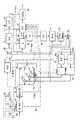
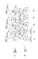
【0012】
図20は、上述した原理に基づいて、動画像信号を符号化して伝送し、これを復号化する装置の具体構成例を示している。1は全体として符号化装置の構成を示し、入力された動画像信号VDを符号化し、伝送路としての記録媒体3に伝送するようになされている。そして2は全体として復号化装置の構成を示し、記録媒体3に記録された信号を再生し、これを復号して映像信号を出力するようになされている。
【0013】
符号化装置1においては、入力された映像信号VDが前処理回路11に入力され、そこで輝度信号と色信号(この例の場合、色差信号)に分離され、それぞれA/D変換器12、13でA/D変換される。A/D変換器12、13によりA/D変換されてデジタル信号となつた映像信号は、フレームメモリ14に供給され書き込まれる。輝度信号は輝度信号フレームメモリ15に、また色差信号は色差信号フレームメモリ16にそれぞれ書き込まれる。
【0014】
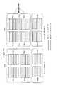
フオーマツト変換回路17は、フレームメモリ14に書き込まれたフレームフオーマツトの信号を、ブロツクフオーマツトの信号に変換する。すなわち、図21に示すように、フレームメモリ14に書き込まれた画像信号は、1ライン当りHドツトの画素よりなるラインがVライン集められたフレームフオーマツトのデータとされている。フオーマツト変換回路17は、この1フレームの信号を、16ラインを単位としてM個のスライスに区分する。
【0015】
そして各スライスは、M個のマクロブロツクに分割される。各マクロブロツクは、16×16個の画素(ドツト)に対応する輝度信号により構成され、この輝度信号はさらに8×8ドツトを単位とするブロツクY[1]〜Y[4]に区分される。そしてこの16×16ドツトの輝度信号には、8×8ドツトのCb信号と、8×8ドツトのCr信号の2ブロツクの色差信号が対応する。
【0016】
このように、ブロツクフオーマツトに変換されたデータBDは、フオーマツト変換回路17からエンコーダ18に供給され、ここでエンコード(符号化)される。その詳細については、図22を参照して後述する。エンコーダ18によりエンコードされた信号は、ビツトストリームとして記録媒体3に記録され、または伝送路に出力される。
【0017】
記録媒体3より再生されたデータは、復号化装置2のデコーダ31に供給されてデコード(復号化)される。デコーダ31の詳細については、図25を参照して後述する。デコーダ31によりデコードされたデータは、フオーマツト変換回路32に入力され、ブロツクフオーマツトからフレームフオーマツトに変換される。そして、フレームフオーマツトの輝度信号は、フレームメモリ33の輝度信号フレームメモリ34に供給されて書き込まれ、色差信号は色差信号フレームメモリ35に供給されて書き込まれる。輝度信号フレームメモリ34と色差信号フレームメモリ35より読み出された輝度信号と色差信号は、D/A変換器36と37によりそれぞれD/A変換され、後処理回路38に供給されて合成される。そして例えばCRT等のデイスプレイ(図示せず)に出力され表示される。
【0018】
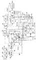
次に図22を参照して、エンコーダ18の構成例について説明する。符号化されるべき画像データBDは、マクロブロツク単位で動きベクトル検出回路(MV−Det)50に入力される。動きベクトル検出回路50は、予め設定されている所定のシーケンスに従つて、各フレームの画像データを、Iピクチヤ、Pピクチヤ又はBピクチヤとして処理する。シーケンシヤルに入力される各フレームの画像を、I、P、Bのいずれのピクチヤとして処理するかは予め定められている。例えば、図18に示したように、フレームF1〜F17により構成されるグループオブピクチヤが、I、B、P、B、P、……B、Pとして処理される。
【0019】
Iピクチヤとして処理されるフレーム(例えばフレームF1)の画像データは、動きベクトル検出回路50からフレームメモリ51の前方原画像部51aに転送されて記憶され、Bピクチヤとして処理されるフレーム(例えばフレームF2)の画像データは、原画像部51bに転送されて記憶され、Pピクチヤとして処理されるフレーム(例えばフレームF3)の画像データは、後方原画像部51cに転送されて記憶される。
【0020】
また次のタイミングにおいて、さらにBピクチヤ(フレームF4)又はPピクチヤ(フレームF5)として処理すべきフレームの画像が入力されたとき、それまで後方原画像部51cに記憶されていた最初のPピクチヤ(フレームF3)の画像データが、前方原画像部51aに転送され、次のBピクチヤ(フレームF4)の画像データが、原画像部51bに記憶(上書き)され、次のPピクチヤ(フレームF5)の画像データが、後方原画像部51cに記憶(上書き)される。このような動作が順次繰り返される。
【0021】
フレームメモリ51に記憶された各ピクチヤの信号は、そこから読み出され、予測モード切り替え回路(Mode−SW)52において、フレーム予測モード処理、又はフイールド予測モード処理が行われる。さらにまた予測判定回路54の制御の下に、演算部53において、画像内予測、前方予測、後方予測又は両方向予測の演算が行われる。これらの処理のうちいずれの処理を行うかは、予測誤差信号(処理の対象とされている参照画像と、これに対する予測画像との差分)に対応して決定される。このため、動きベクトル検出回路50は、この判定に用いられる予測誤差信号の絶対値和(自乗和でもよい)を生成する。
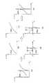
【0022】
ここで、予測モード切り替え回路52におけるフレーム予測モードとフイールド予測モードについて説明する。フレーム予測モードが設定された場合において予測モード切り替え回路52は、動きベクトル検出回路50より供給される4個の輝度ブロツクY[1]〜Y[4]を、そのまま後段の演算部53に出力する。すなわちこの場合においては、図23(A)に示すように、各輝度ブロツクに奇数フイールドのラインのデータと、偶数フイールドのラインのデータとが混在した状態となつている。このフレーム予測モードにおいては、4個の輝度ブロツク(マクロブロツク)を単位として予測が行われ、4個の輝度ブロツクに対して1個の動きベクトルが対応される。
【0023】
これに対して、予測モード切り替え回路52は、フイールド予測モードにおいては、図23(A)に示す構成で動きベクトル検出回路50より入力される信号を、図23(B)に示すように、4個の輝度ブロツクのうち、輝度ブロツクY[1]とY[2]を、例えば奇数フイールドのラインのドツトによりのみ構成させ、他の2個の輝度ブロツクY[3]とY[4]を、偶数フイールドのラインのデータにより構成させて、演算部53に出力する。この場合においては、2個の輝度ブロツクY[1]とY[2]に対して、1個の動きベクトルが対応され、他の2個の輝度ブロツクY[3]とY[4]に対して、他の1個の動きベクトルが対応される。
【0024】
動きベクトル検出回路50は、フレーム予測モードにおける予測誤差の絶対値和と、フイールド予測モードにおける予測誤差の絶対値和を、予測モード切り替え回路52に出力する。予測モード切り替え回路52は、フレーム予測モードとフイールド予測モードにおける予測誤差の絶対値和を比較し、その値が小さい予測モードに対応する処理を施して、データを演算部53に出力する。一般には、動画像の動きが速い場合にはフイールド予測モードが選択され、動きの遅い場合にはフレーム予測モードが選択される。
【0025】
ただしこのような処理は、実際には動きベクトル検出回路50で行われる。すなわち動きベクトル検出回路50は、決定されたモードに対応する構成の信号を予測モード切り替え回路52に出力し、予測モード切り替え回路52は、その信号を、そのまま後段の演算部53に出力する。なお色差信号は、フレーム予測モードの場合、図23(A)に示すように、奇数フイールドのラインのデータと偶数フイールドのラインのデータとが混在する状態で、演算部53に供給される。またフイールド予測モードの場合、図23(B)に示すように、各色差ブロツクCb、Crの上半分(4ライン)が、輝度ブロツクY[1]、Y[2]に対応する奇数フイールドの色差信号とされ、下半分(4ライン)が、輝度ブロツクY[3]、Y[4]に対応する偶数フイールドの色差信号とされる。
【0026】
また動きベクトル検出回路50は、次のようにして予測判定回路54において、画像内予測、前方予測、後方予測又は両方向予測のいずれの予測を行うかを決定するための予測誤差の絶対値和を生成する。すなわち、画像内予測の予測誤差の絶対値和として、参照画像のマクロブロツクの信号Aijの和ΣAijの絶対値|ΣAij|と、マクロブロツクの信号Aijの絶対値|Aij|の和Σ|Aij|の差を求める。また前方予測の予測誤差の絶対値和として、参照画像のマクロブロツクの信号Aijと、予測画像のマクロブロツクの信号Bijの差Aij−Bijの絶対値|Aij−Bij|の和Σ|Aij−Bij|を求める。また、後方予測と両方向予測の予測誤差の絶対値和も、前方予測における場合と同様に(その予測画像を前方予測における場合と異なる予測画像に変更して)求める。
【0027】
これらの絶対値和は、予測判定回路54に供給される。予測判定回路54は、前方予測、後方予測及び両方向予測の予測誤差の絶対値和のうち、最も小さいものをインター予測の予測誤差の絶対値和として選択する。さらにこのインター予測の予測誤差の絶対値和と、画像内予測の予測誤差の絶対値和とを比較し、その小さい方を選択し、この選択した絶対値和に対応するモードを予測モード(P-mode)として選択する。すなわち画像内予測の予測誤差の絶対値和の方が小さければ、画像内予測モードが設定される。インター予測の予測誤差の絶対値和の方が小さければ、前方予測、後方予測又は両方向予測モードのうち、対応する絶対値和が最も小さかつたモードが設定される。
【0028】
このように動きベクトル検出回路50は、参照画像のマクロブロツクの信号を、フレーム又はフイールド予測モードのうち、予測モード切り替え回路52により選択されたモードに対応する構成で、予測モード切り替え回路52を介して演算部53に供給すると共に、4つの予測モードのうち、予測判定回路54により選択された予測モード(P-mode)に対応する予測画像と参照画像の間の動きベクトルMVを検出し、可変長符号化回路(VLC)58と動き補償回路(M−comp)64に出力する。上述したように、この動きベクトルとしては、対応する予測誤差の絶対値和が最小となるものが選択される。
【0029】
予測判定回路54は、動きベクトル検出回路50が前方原画像部51aよりIピクチヤの画像データを読み出しているとき、予測モードとしてフレーム(画像)内予測モード(動き補償を行わないモード)を設定し、演算部53のスイツチを接点a側に切り替える。これによりIピクチヤの画像データがDCTモード切り替え回路(DCT CTL)55に入力される。
【0030】
このDCTモード切り替え回路55は、図24(A)又は(B)に示すように、4個の輝度ブロツクのデータを、奇数フイールドのラインと偶数フイールドのラインが混在する状態(フレームDCTモード)、または分離された状態(フイールドDCTモード)のいずれかの状態にして、DCT回路56に出力する。すなわちDCTモード切り替え回路55は、奇数フイールドと偶数フイールドのデータを混在してDCT処理した場合における符号化効率と、分離した状態においてDCT処理した場合の符号化効率とを比較し、符号化効率の良好なモードを選択する。
【0031】
例えば入力された信号を、図24(A)に示すように、奇数フイールドと偶数フイールドのラインが混在する構成とし、上下に隣接する奇数フイールドのラインの信号と偶数フイールドのラインの信号の差を演算し、さらにその絶対値の和(または自乗和)を求める。また入力された信号を、図24(B)に示すように、奇数フイールドと偶数フイールドのラインが分離した構成とし、上下に隣接する奇数フイールドのライン同士の信号の差と、偶数フイールドのライン同士の信号の差を演算し、それぞれの絶対値の和(または自乗和)を求める。
【0032】
さらに両者(絶対値和)を比較し、小さい値に対応するDCTモードを設定する。すなわち前者の方が小さければ、フレームDCTモードを設定し、後者の方が小さければ、フイールドDCTモードを設定する。そして選択したDCTモードに対応する構成のデータをDCT回路56に出力するとともに、選択したDCTモードを示すDCTフラグ(DCT-FLG)を、可変長符号化回路58と動き補償回路64に出力する。
【0033】
予測モード切り替え回路52における予測モード(図23)と、このDCTモード切り替え回路55におけるDCTモード(図24)を比較して明らかなように、輝度ブロツクに関しては両者の各モードにおけるデータ構造は実質的に同一である。一般には予測モード切り替え回路52において、フレーム予測モードが選択された場合、DCTモード切り替え回路55においても、フレームDCTモードが選択される可能性が高い。
【0034】
また予測モード切り替え回路52において、フイールド予測モードが選択された場合、DCTモード切り替え回路55においても、フイールドDCTモードが選択される可能性が高い。しかしながら必ずしも常にそのようになされるわけではなく、予測モード切り替え回路52においては、予測誤差の絶対値和が小さくなるようにモードが決定される。またDCTモード切り替え回路55においては、符号化効率が良好となるようにモードが決定される。
【0035】
DCTモード切り替え回路55より出力されたIピクチヤの画像データは、DCT回路56に入力され、DCT(離散コサイン変換)処理され、DCT係数に変換される。このDCT係数は、量子化回路(Q)57に入力され、送信バツフア(Buffer)59のデータ蓄積量(バツフア蓄積量(B-full))に対応した量子化ステツプで量子化された後、可変長符号化回路58に入力される。可変長符号化回路58は、量子化回路57より供給される量子化ステツプ(スケール(QS))に対応して、量子化回路57より供給される画像データ(この場合、Iピクチヤのデータ)を、例えばハフマン符号などの可変長符号に変換して、送信バツフア59に出力する。
【0036】
可変長符号化回路58にはまた、量子化回路57より量子化ステツプ(スケール(QS))、予測判定回路54より予測モード(画像内予測、前方予測、後方予測又は両方向予測のいずれが設定されたかを示すモード(P-mode))、動きベクトル検出回路50より動きベクトル(MV)、予測モード切り替え回路52より予測フラグ(フレーム予測モード又はフイールド予測モードのいずれが設定されたかを示すフラグ(P-FLG))、およびDCTモード切り替え回路55が出力するDCTフラグ(フレームDCTモード又はフイールドDCTモードのいずれが設定されたかを示すフラグ(DCT-FLG))が入力されており、これらも可変長符号化される。
【0037】
送信バツフア59は、入力されたデータを一時蓄積し、蓄積量に対応するデータを量子化回路57に出力する。送信バツフア59は、そのデータ残量が許容上限値まで増量すると、量子化制御信号(B-full)によつて量子化回路57の量子化スケールを大きくすることにより、量子化データのデータ量を低下させる。またこれとは逆に、データ残量が許容下限値まで減少すると、送信バツフア59は、量子化制御信号(B-full)によつて量子化回路57の量子化スケールを小さくすることにより、量子化データのデータ量を増大させる。このようにして、送信バツフア59のオーバフロー又はアンダフローが防止される。そして送信バツフア59に蓄積されたデータは、所定のタイミングで読み出され、伝送路に出力され又は記録媒体3に記録される。
【0038】
一方量子化回路57より出力されたIピクチヤのデータは、逆量子化回路(IQ)60に入力され、量子化回路(QS)57より供給される量子化ステツプに対応して逆量子化される。逆量子化回路60の出力は、逆DCT(IDCT)回路61に入力されて逆DCT処理された後、ブロツク並び換え回路(Block
Change)65により、各DCTモード(フレーム/フイールド)に対応してブロツクの並び換えが行われる。ブロツク並び換え回路65の出力信号は、演算器62を介してフレームメモリ63の前方予測画像部(F−P)63aに供給されて記憶される。
【0039】
動きベクトル検出回路50は、シーケンシヤルに入力される各フレームの画像データを、例えばI、B、P、B、P、B……のピクチヤとしてそれぞれ処理する場合、最初に入力されたフレームの画像データをIピクチヤとして処理した後、次に入力されたフレームの画像をBピクチヤとして処理する前に、さらにその次に入力されたフレームの画像データをPピクチヤとして処理する。Bピクチヤは、後方予測を伴うため、後方予測画像としてのPピクチヤが先に用意されていないと、復号することができないからである。
【0040】
そこで動きベクトル検出回路50は、Iピクチヤの処理の次に、後方原画像部51cに記憶されているPピクチヤの画像データの処理を開始する。そして、上述した場合と同様に、マクロブロツク単位でのフレーム間差分(予測誤差)の絶対値和が、動きベクトル検出回路50から予測モード切り替え回路52と予測判定回路54に供給される。予測モード切り替え回路52と予測判定回路54は、このPピクチヤのマクロブロツクの予測誤差の絶対値和に対応して、フレーム/フイールド予測モード、または画像内予測、前方予測、後方予測もしくは両方向予測の予測モードを設定する。
【0041】
演算部53はフレーム内予測モードが設定されたとき、スイツチを上述したように接点a側に切り替える。従つてこのデータは、Iピクチヤのデータと同様に、DCTモード切り替え回路55、DCT回路56、量子化回路57、可変長符号化回路58、送信バツフア59を介して伝送路に伝送される。また、このデータは、逆量子化回路60、逆DCT回路61、ブロツク並び換え回路65、演算器62を介してフレームメモリ63の後方予測画像部(B−P)63bに供給されて記憶される。
【0042】
前方予測モードの時、スイツチが接点bに切り替えられると共に、フレームメモリ63の前方予測画像部63aに記憶されている画像(この場合Iピクチヤの画像)データが読み出され、動き補償回路64により、動きベクトル検出回路50が出力する動きベクトルに対応して動き補償される。すなわち動き補償回路64は、予測判定回路54より前方予測モードの設定が指令されたとき、前方予測画像部63aの読み出しアドレスを、動きベクトル検出回路50がいま出力しているマクロブロツクの位置に対応する位置から動きベクトルに対応する分だけずらしてデータを読み出し、予測画像データを生成する。
【0043】
動き補償回路64より出力された予測画像データは、演算器53aに供給される。演算器53aは、予測モード切り替え回路52より供給された参照画像のマクロブロツクのデータから、動き補償回路64より供給されたこのマクロブロツクに対応する予測画像データを減算し、その差分(予測誤差)を出力する。この差分データは、DCTモード切り替え回路55、DCT回路56、量子化回路57、可変長符号化回路58、送信バツフア59を介して伝送路に伝送される。また、この差分データは、逆量子化回路60、逆DCT回路61により局所的に復号され、ブロツク並び換え回路65を介して演算器62に入力される。
【0044】
この演算器62にはまた演算器53aに供給されている予測画像データと同一のデータが供給されている。演算器62は、逆DCT回路61が出力する差分データに、動き補償回路64が出力する予測画像データを加算する。これにより元の(復号した)Pピクチヤの画像データが得られる。このPピクチヤの画像データは、フレームメモリ63の後方予測画像部63bに供給され、記憶される。
【0045】
動きベクトル検出回路50は、このようにIピクチヤとPピクチヤのデータが前方予測画像部63aと後方予測画像部63bにそれぞれ記憶された後、次にBピクチヤの処理を実行する。予測モード切り替え回路52と予測判定回路54は、マクロブロツク単位でのフレーム間差分の絶対値和の大きさに対応して、フレーム/フイールドモードを設定し、また予測モードをフレーム内予測モード、前方予測モード、後方予測モード又は両方向予測モードのいずれかに設定する。上述したように、フレーム内予測モード又は前方予測モードの時、スイツチは接点a又はbに切り替えられる。このときPピクチヤにおける場合と同様の処理が行われデータが伝送される。
【0046】
これに対して、後方予測モード又は両方向予測モードが設定された時、スイツチは、接点c又はdにそれぞれ切り替えられる。スイツチが接点cに切り替えられている後方予測モードの時、後方予測画像部63bに記憶されている画像(この場合、Pピクチヤの画像)データが読み出され、動き補償回路64により、動きベクトル検出回路50が出力する動きベクトルに対応して動き補償される。すなわち動き補償回路64は、予測判定回路54より後方予測モードの設定が指令されたとき、後方予測画像部63bの読み出しアドレスを、動きベクトル検出回路50がいま出力しているマクロブロツクの位置に対応する位置から動きベクトルに対応する分だけずらしてデータを読み出し、予測画像データを生成する。
【0047】
動き補償回路64より出力された予測画像データは、演算器53bに供給される。演算器53bは、予測モード切り替え回路52より供給された参照画像のマクロブロツクのデータから、動き補償回路64より供給された予測画像データを減算しその差分を出力する。この差分データは、DCTモード切り替え回路55、DCT回路56、量子化回路57、可変長符号化回路58、送信バツフア59を介して伝送路に伝送される。
【0048】
スイツチが接点dに切り替えられている両方向予測モードの時、前方予測画像部63aに記憶されている画像(この場合、Iピクチヤの画像)データと、後方予測画像部63bに記憶されている画像(この場合、Pピクチヤの画像)データが読み出され、動き補償回路64により、動きベクトル検出回路50が出力する動きベクトルに対応して動き補償される。
【0049】
すなわち、動き補償回路64は、予測判定回路54より両方向予測モードの設定が指令されたとき、前方予測画像部63aと後方予測画像部63bの読み出しアドレスを、動きベクトル検出回路50がいま出力しているマクロブロツクの位置に対応する位置から動きベクトル(この場合の動きベクトルは、前方予測画像用と後方予測画像用の2つとなる)に対応する分だけずらしてデータを読み出し、予測画像データを生成する。
【0050】
動き補償回路64より出力された予測画像データは、演算器53cに供給される。演算器53cは、動きベクトル検出回路50より供給された参照画像のマクロブロツクのデータから、動き補償回路64より供給された予測画像データの平均値を減算し、その差分を出力する。この差分データは、DCTモード切り替え回路55、DCT回路56、量子化回路57、可変長符号化回路58、送信バツフア59を介して伝送路に伝送される。
【0051】
Bピクチヤの画像は、他の画像の予測画像とされることがないため、フレームメモリ63には記憶されない。なおフレームメモリ63において、前方予測画像部63aと後方予測画像部63bは、必要に応じてバンク切り替えが行われ、所定の参照画像に対して、一方又は他方に記憶されているものを、前方予測画像あるいは後方予測画像として切り替えて出力することができる。
【0052】
上述の処理においては、輝度ブロツクを中心として説明したが、色差ブロツクについても同様に、図23及び図24に示すマクロブロツクを単位として処理される。なお色差ブロツクを処理する場合の動きベクトルは、対応する輝度ブロツクの動きベクトルを垂直方向と水平方向に、それぞれ1/2にしたものが用いられる。
【0053】
次に図25は、図20のデコーダ31の一例の構成を示すブロツク図である。伝送路又は記録媒体を介して供給される画像データは、図示せぬ受信回路で受信され又は再生装置で再生され、受信バツフア(Buffer)81に一時記憶される。その後、復号回路90の可変長復号化回路(IVLC)82に供給される。
【0054】
可変長復号化回路(IVLC)82は、受信バツフア81より供給されたデータを可変長復号化し、動きベクトル(MV)、予測モード(P-mode)及び予測フラグ(P-FLG)を動き補償回路(M−comp)87に供給する。またDCTフラグ(DCT-FLG)は逆ブロツク並び換え回路(Block Change)88に、量子化ステツプ(QS)を逆量子化回路(IQ)83に、それぞれ出力するとともに、復号された画像データを逆量子化回路83に出力する。
【0055】
逆量子化回路83は、可変長復号化回路82より供給された画像データを、同じく可変長復号化回路82より供給された量子化ステツプに従つて逆量子化し、逆DCT回路84に出力する。逆量子化回路83より出力されたデータ(DCT係数)は、逆DCT回路84で逆DCT処理されて演算器85に供給される。
【0056】
逆DCT回路84より供給された画像データが、Iピクチヤのデータである場合、そのデータは演算器85より出力され、演算器85に後に入力される画像データ(PまたはBピクチヤのデータ)の予測画像データ生成のために、フレームメモリ86の前方予測画像部(F−P)86aに供給されて記憶される。またこのデータはフオーマツト変換回路32(図20)に出力される。
【0057】
逆DCT回路84より供給された画像データが、その1フレーム前の画像データを予測画像データとするPピクチヤのデータであつて、前方予測モードのデータである場合、フレームメモリ86の前方予測画像部86aに記憶されている1フレーム前の画像データ(Iピクチヤのデータ)が読み出され、動き補償回路87で可変長復号化回路82より出力された動きベクトルに対応する動き補償が施される。
【0058】
そして演算器85において、逆DCT回路84より供給された画像データ(差分のデータ)と加算され出力される。この加算されたデータ、すなわち復号されたPピクチヤのデータは、演算器85に後に入力される画像データ(Bピクチヤ又はPピクチヤのデータ)の予測画像データ生成のために、フレームメモリ86の後方予測画像部(B−P)86bに供給されて記憶される。
【0059】
Pピクチヤのデータであつても画像内予測モードのデータは、Iピクチヤのデータと同様に演算器85で特に処理は行わず、そのまま後方予測画像部86bに記憶される。このPピクチヤは次のBピクチヤの次に表示されるべき画像であるため、この時点ではまだフオーマツト変換回路32へ出力されない。すなわち上述したようにBピクチヤの後に入力されたPピクチヤが、Bピクチヤより先に処理され、伝送されている。
【0060】
逆DCT回路84より供給された画像データが、Bピクチヤのデータである場合、可変長復号化回路82より供給された予測モードに対応して、フレームメモリ86の前方予測画像部86aに記憶されているIピクチヤの画像データ(前方予測モードの場合)、後方予測画像部86bに記憶されているPピクチヤの画像データ(後方予測モードの場合)、またはその両方の画像データ(両方向予測モードの場合)が読み出され、動き補償回路87において、可変長復号化回路82より出力された動きベクトルに対応する動き補償が施されて、予測画像が生成される。ただし動き補償を必要としない場合すなわち画像内予測モードの場合、予測画像は生成されない。
【0061】
このようにして動き補償回路87で動き補償が施されたデータは、演算器85において、逆DCT回路84の出力と加算される。この加算出力はフオーマツト変換回路32に出力される。ただしこの加算出力はBピクチヤのデータであり、他の画像の予測画像生成のために利用されることがないため、フレームメモリ86には記憶されない。Bピクチヤの画像が出力された後、後方予測画像部86bに記憶されているPピクチヤの画像データが読み出され、動き補償回路87を介して演算器85に供給される。ただしこのとき動き補償は行われない。
【0062】
なおこのデコーダ31には図22のエンコーダ18における予測モード切り替え回路52とDCTモード切り替え回路55に対応する回路を図示していない。これらの回路に対応する処理、すなわち奇数フイールドと偶数フイールドのラインの信号が分離された構成を、元の混在する構成に必要に応じて戻す処理は、動き補償回路87が実行するためである。また上述の処理においては、輝度信号の処理について説明したが、色差信号の処理も同様に行われる。ただし、この場合動きベクトルは、輝度信号用のものを垂直方向及び水平方向に1/2にしたものが用いられる。
【0063】
【発明が解決しようとする課題】
ところで上述の画像符号化における変換符号化は、入力信号の相関を利用し、ある特定の座標軸に信号電力を集中させることにより情報量の圧縮を可能とする。DCTはこうした変換符号化に用いられる変換方式、特に直交変換の1例である。DCTは画像信号の持つ2次元相関性を利用して、ある特定の周波数成分に信号電力を集中させ、この集中分布した係数のみを符号化することで情報量の圧縮を可能とする。例えば、絵柄が平坦で画像信号の自己相関性が高い部分では、DCT係数は低周波数成分へ集中分布し、他の成分は小さな値となる。従つてこの場合は低域へ集中分布した係数のみを符号化することで、情報量の圧縮が可能となる。
【0064】
ところが画像のエツジ等のように輪郭を含む画像信号では、DCT係数は低周波から高周波数成分まで広く分散して発生する。すると輪郭のような信号の不連続点をDCT係数で精度良く表すためには、非常に多くの係数を必要とし、符号化効率が落ちることになる。このとき従来のように画像の高圧縮符号化のために係数の量子化特性を粗くしたり、高周波数成分の係数を打ち切つたりすると、画像信号の劣化が目立ち、例えば輪郭のまわりに揺らぎのような歪み(コロナイフエクト又はモスキートノイズ等、以下簡単にノイズという)が発生する。
【0065】
また画像符号化においては動き補償予測を用いているために、上述したようなノイズは次々と予測フレームに伝播し、時間方向へ伝播されていく。その結果再生画像では、ノイズが不規則に揺らいでいるように見え、視覚上非常に不快に感じられるようになる。この問題を解決するために、前置フイルタ及び後置フイルタが用いられる。前置フイルタとして例えば、ローパスフイルタを用い、符号化効率を向上させることで、ノイズの発生を抑制することができる。また後置フイルタとしても、ローパスフイルタを用い発生したノイズを目立たないように除去するために用いられる。こうした後置フイルタとしては例えばεフイルタやメデイアンフイルタがある。
【0066】
ところがこのように、モスキートノイズを低減するために前置フイルタや後置フイルタを用いると、モスキートノイズを低減するだけでなく画像信号がもつ視覚的重要な情報をも損失させてしまう。すなわちSN比が悪い信号帯域では、画像の歪みと画像の細かい模様の区別が難しく、ローパスフイルタにより、画像の平坦部にある模様をも失われぼやけた画像になつてしまう問題がある。
【0067】
本発明は以上の点を考慮してなされたもので、SN比が悪い信号帯域でもノイズを低減させながら画像の細かい模様の情報の低減を最小限に押え得る動画像符号化方法、動画像復号化方法及び動画像符号化装置を提案しようとするものである。
【0068】
【課題を解決するための手段】
かかる課題を解決するため本発明は、動画像符号化方法であって、動画像信号に対する前処理結果として入力されるブロック単位の信号を高周波成分及び低周波成分に分割し、当該高周波成分におけるエッジ情報、振幅情報及び輝度信号と色差信号との相関を調べ、その調べた結果に応じて使用する非線形量子化特性を決定し、決定された非線形量子化特性に従って高周波成分を量子化し、量子化された高周波成分と、低周波成分とを合成し、当該合成結果に対して直交変換処理を施すようにした。
【0070】
また本発明は、動画像復号化方法であって、動画像符号化信号に対するブロック単位での復元処理結果として得られたブロック単位の信号を高周波成分及び低周波成分に分割し、当該高周波成分におけるエッジ情報、振幅情報及び輝度信号と色差信号との相関を調べ、その調べた結果に応じて使用する非線形逆量子化特性を決定し、決定された非線形逆量子化特性に従って高周波成分を逆量子化し、逆量子化された高周波成分と、低周波成分とを合成するようにした。
【0071】
さらに本発明は、動画像符号化装置であって、動画像信号に対する前処理結果として入力されるブロック単位の信号を高周波成分及び低周波成分に分割する分割手段と、分割手段により分割された高周波成分におけるエッジ情報、振幅情報及び輝度信号と色差信号との相関を調べ、当該調べた結果に応じて使用する非線形量子化特性を決定する特性決定手段と、特性決定手段により決定された非線形量子化特性に従って高周波成分を量子化する高周波成分量子化手段と、高周波成分量子化手段により量子化された高周波成分と、低周波成分とを合成する合成手段と、合成手段により合成された結果に対して直交変換処理を施す直交変換手段とを設けるようにした。
【0072】
さらに本発明は、動画像復号化方法であって、動画像符号化信号に対するブロック単位での復元処理結果として得られたブロック単位の信号を高周波成分及び低周波成分に分割する分割手段と、分割手段により分割された高周波成分におけるエッジ情報、振幅情報及び輝度信号と色差信号との相関を調べ、当該調べた結果に応じて使用する非線形逆量子化特性を決定する特性決定手段と、特性決定手段により決定された非線形逆量子化特性に従って高周波成分を逆量子化する高周波成分逆量子化手段と、高周波成分逆量子化手段により逆量子化された高周波成分と、低周波成分とを合成する合成手段とを設けるようにした。
【0073】
【作用】
動画像信号を所定の予測画像信号を用いてモードの切り替えを行い、当該モードの切り替えられた信号を直交変換し、当該直交変換した信号を量子化し、量子化した信号を可変長符号化して符号化処理する際に、動画像信号のSN比が低下する信号の帯域を、非線形特性に基づいて量子化して強調させる。そして復号側においては、符号側と逆の特性をもつ非線形特性に基づいて動画像符号化信号を逆量子化し復調する。これにより、画像の歪みと画像の細かい模様の区別がし難かつた場合でも、画像信号の平坦部にある模様の低減を押えることができるので、ノイズを低減させながら画像の細かい模様情報の低減は押え、SN比の改善と視覚的印象を改善し得る。
【0074】
【実施例】
以下図面について、本発明の一実施例を詳述する。
【0075】
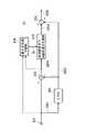
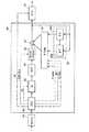
(1)第1の実施例
図1においては全体として本発明の第1の実施例を示し、この実施例では非線形量子化回路(NLQ)70及び非線形逆量子化回路(NLIQ)71を除き、上述した図22に示す従来の動画像符号化装置と同様の構成である。非線形量子化回路70を図2を用いて説明する。すなわち、非線形量子化回路70には、フレーム内符号化マクロブロツクの場合にはブロツクの画素値が、またフレーム間符号化マクロブロツクの場合には動き補償を行つた後のフレーム間差分値が、それぞれ入力端子200に供給される。入力端子200に供給された画像信号S201は、ローパスフイルタ(LPF)201及び加算器202に入力される。ローパスフイルタ201では入力画像信号S201の低周波成分が取り出される。ローパスフイルタ201の出力は加算器202及び204に出力される。
【0076】
加算器202では入力画像信号S201とローパスフイルタ201の出力値S202の差分が計算され出力される(S203)。ローパスフイルタ201の出力値S202は画像信号の低周波成分であるから、加算器202の出力S203は画像の高周波成分の振幅を示す信号である。信号S203は高周波信号の非線形量子化回路203及び量子化回路の制御器206に入力される。
【0077】
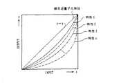
高周波信号の非線形量子化回路203は図3に示す非線形特性を用い、非線形量子化を行う。図中の横軸は入力画像信号S203の値(振幅値)であり、縦軸は出力信号S204の値(振幅値)である。なおここでは、正側特性のみを示す。負側は、原点対象である。y=xが示す点線が、通常の線形量子化特性を表す。線形量子化特性を用いる場合、高周波信号の非線形量子化回路203の入力信号S203と出力信号S204は同一の信号となり、従つて非線形量子化回路70の入力信号と出力信号は同一の信号となる。図3では非線形特性をNCとして一例を示すが、非線形量子化特性はいくつか考えられる。従つて図3の特性の場合、入力信号S203よりも大きな値がS204として出力される。
【0078】
高周波信号の非線形量子化回路203の非線形量子化特性は適応的に切替えることも可能である。量子化回路の制御器206は高周波信号の非線形量子化回路203の高周波信号S203の性質を検査し、その性質に応じて非線形量子化特性を決定し、量子化特性を示す信号QLを高周波信号の非線形量子化回路203に出力する。この実施例においては量子化回路の制御器は使用せず、常に同一の量子化特性を用いる。高周波信号の非線形量子化回路203の出力信号S204は加算器204に入力される。加算器204では信号S204及びローパスフイルタ201の出力信号S202を加算しその和を出力する(S205)。
【0079】
S202は非線形量子化回路70に入力された画像信号S201の低周波成分であり、S204はS201の非線形量子化後の高周波成分である。従つて非線形量子化回路70の出力S205は入力信号S201の高周波成分を強調した信号となる。非線形量子化回路70によつて高域が強調された画像信号は、DCT回路56に入力される。
【0080】
従来と同様にDCT回路56はDCT変換を行い、量子化回路57に変換後の値を入力し、量子化後の値は可変長符号化回路58に入力される。また量子化回路57の出力は、逆量子化回路60にも入力される。逆量子化回路60では量子化回路57の逆の操作を行う。逆DCT回路61は逆量子化回路60の出力値を逆DCT変換した後、復元された信号を非線形逆量子化回路71に入力する。
【0081】
非線形逆量子化回路71は図4に示すように構成され、非線形量子化回路70の逆の操作を行う。非線形逆量子化回路71の入力端400より入力された信号S401はローパスフイルタ401及び加算器402に入力される。ローパスフイルタ401では信号S401の低周波成分が抽出される。ローパスフイルタ401の出力信号S402は加算器402及び404に入力される。加算器402では信号S401及びS402の差分が求められ出力される(S403)。これにより信号S402は信号S401の低周波成分、信号S403は信号S401の高周波成分を表す。信号S403は高周波信号の非線形逆量子化回路403に入力される。
【0082】
高周波信号の非線形逆量子化回路403は図5に示す非線形特性INCを用い、非線形量子化を行う。図5に示す非線形特性INCは、図3に示した非線形特性NCと対称な特性を有する。すなわち、図3及び図5における各特性は、直線y=xに対して対称となつている。なおここでも、正側特性のみを示す。負側は、原点対象である。
【0083】
図5の横軸は入力画像信号S403の値(振幅値)であり、縦軸は出力信号S404の値(振幅値)である。y=xが示す点線が線形逆量子化特性を表す。線形量子化特性を用いる場合、高周波信号の非線形逆量子化回路403の入力信号S403と出力信号S404は同一の信号となり、従つて非線形逆量子化回路71の入力信号と出力信号は同一の信号となる。
【0084】
逆量子化回路の制御器406は、高周波信号の非線形逆量子化回路403で使用する逆量子化特性を決定し、使用する逆量子化特性を示す信号QLを高周波信号の非線形逆量子化回路403に出力する。逆量子化回路の制御器406は高周波信号S403の性質を検査し、その性質に従つて使用する逆量子化特性を決定するか、または外部から入力される逆量子化特性を指示する信号(QL)に従つて使用する逆量子化特性を決定する。
【0085】
この実施例においては、常に同一の逆量子化特性を用いるため、逆量子化回路の制御器406は使用しない。また高周波信号の非線形逆量子化回路403で使用する逆量子化特性は、高周波信号の非線形量子化回路203で使用した量子化特性の逆の操作を行う逆量子化特性でなければならない。高周波信号の非線形逆量子化回路403の出力は、加算器404に入力される。加算器404は信号S404及び信号S402を加算し出力する(S405)。以上のように非線形逆量子化回路71は非線形量子化回路70により強調された高周波成分をもとに戻す操作を行う。
【0086】
このような非線形量子化操作が、変換符号化によつて生じたモスキートノイズ等のノイズを低減する原理を説明する。図6は図2の非線形量子化回路70での信号の変化の様子を示す。(a)は信号S201の1例である。(a)の信号はローパスフイルタ201により(b)のような低周波成分が抽出される。これが信号S202である。
【0087】
一方加算器202によりS201とS202の差分がとられ、高周波成分として信号S203が(d)のように出力される。このときの信号の最大値と平坦部の差をA1とする。このとき高周波成分を非線形量子化することにより強調する。高周波信号の非線形量子化回路203の出力S204を(e)に示す。このとき信号の最大値と平坦部の差はA2となる(A2>A1)。加算器204は信号S202と信号S204を加算し、出力信号S205を生成する(f)。
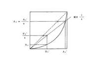
【0088】
図7に非線形量子化特性を示す。横軸は入力信号の値、縦軸は出力信号の値である。なおここでは、正側特性のみを示す。負側は、原点対象である。ここで、変換符号化の際に生じる歪み、ノイズ成分の最大値は変換回路(この実施例の場合DCT回路)に入力する信号の最大値の50%の値を持つと仮定する。すなわち、変換回路への入力の最大値と線形の関係にある。入力信号の最大値がA1である場合を考える。非線形量子化を行わない場合、変換符号化によつて生じる歪みの最大値はN1であるとする(図7)。非線形量子化を行つた場合、A1はA2=a×A1となる。このとき、歪みの最大値はDCTに入力する信号の50%であることから、非線形量子化後の値をDCT変換することによつて生じる歪みの最大値は、N2=a×N1となると考えられる。
【0089】
図8は、図4の非線形逆量子化回路71での信号の変化の様子を示す。(a)は図6の(f)の信号をDCT変換回路56、量子化回路57、逆量子化回路60、逆DCT回路61によつて処理を行つた後、非線形逆量子化回路71に入力された信号S401を示す。信号S401からローパスフイルタ401により低周波成分S402が抽出される。信号S402を(b)に示す。
【0090】
加算器402は信号S401と信号S402の差分をとることにより、高周波成分S403を抽出する。S403を(d)に示す。この(d)に示される信号には、変換符号化によつて生じた歪みが付加されている。このとき信号の最大値はA2′、歪みの最大値はN2′であるとする。
【0091】
高周波信号の非線形逆量子化回路403の出力S403を(e)に示す。また逆量子化特性を図9に示す。非線形逆量子化により、信号の最大値はA3=A2′/aとなる。またこのとき歪みの最大値はN3となる。非線形逆量子化を行わない場合の歪みの最大値は、N2′/aとなる。非線形量子化を行わない場合と比較すると、N1−N3だけ歪みの最大値が減少したことがわかる。
【0092】
以上のような方法により、高周波成分を強調して符号化することにより、歪みを減少させることが可能となる。この非線形量子化操作は、変換回路(この実施例の場合DCT変換回路)に入力するブロツク単位で行う。これは変換符号化によつて生じる劣化は、ブロツク内で閉じているためである。このことにより、ブロツクを越えて必要以上に情報を失うことを防ぐことができる。
【0093】
図10に第1の実施例における動画像復号化装置を示す。非線形逆量子化回路(NLIQ)91を除き、従来と同様であるので、既に従来例にて説明してある部分については、説明を省略する。この非線形逆量子化回路91について説明すると、非線形逆量子化回路91は、図1及び図4に上述した非線形逆量子化回路71と同様の回路であり、非線形量子化回路70と逆の操作を行うためのものである。またこのとき、非線形量子化回路70の持つ非線形量子化特性及び非線形逆量子化回路91の持つ非線形逆量子化特性は、互いに逆の特性を持つ。
【0094】
この実施例においては非線形量子化回路をDCT回路の直前に、また非線形逆量子化回路を逆DCT回路の直後に設けることにより、画像信号符号化装置及び画像信号復号装置の間で整合性を保つことが出来る。またこの実施例における方法では、画像信号復号装置が非線形逆量子化回路を持たない場合においても最低限の画像を再生することが可能である。画像信号復号装置が非線形逆量子化回路を持たない場合、高周波成分が強調されたままの信号が復号され表示される。この場合の画像信号復号装置は従来例と同様である。
【0095】
また非線形逆量子化器71(または91)の逆量子化特性と非線形量子化器70の量子化特性は、互いに正反対の特性である必要は必ずしもない。量子化特性の強調度よりも逆量子化特性の復調度が大きい場合は、復号画像にローパスフィルタをかけた効果が得られ、それと逆の場合には、復号画像に輪郭強調をかけた効果が得られる。
【0096】
以上の構成によれば、符号化によりSN比が悪くなりがちな信号帯域に、非線形特性をもつ前処理及び後処理を連携して施すことにより、SN比を効果的に改善できる。すなわちSN比が悪い信号帯域において、モスキートノイズは低減させながらも、画像の細かい模様情報の低減は押えることができ、これにより、従来画像の歪みと画像の細かい模様の区別が難しかつた場合でも、画像信号の平坦部にある模様の低減を押えることができるので、SN比の改善と視覚的印象の改善を図ることができる。
【0097】
さらに変換符号化における歪みは変換に用いるブロツク内で閉じて発生するので、上述の前処理及び後処理の操作を変換符号化を行うブロツク単位で閉じて行うことにより、モスキートノイズの時間方向への伝搬を小さくすることが可能となる。これにより従来動き補償予測を用いているために、時間方向へ歪みノイズが伝搬することにより見られたノイスの揺らぎが軽減され、視覚的印象の改善を図ることができる。
【0098】
(2)第2の実施例
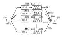
第2の実施例は第1の実施例の変形であり、非線形量子化回路(NLQ)70及び非線形逆量子化回路(NLIQ)71、91を除き上述した第1の実施例と同一構成である。すなわち、第2の実施例における非線形量子化回路70の内部構成を図11に示す。非線形量子化回路70に入力される画像信号S1100は、バンドパスフイルタ1(1101)〜バンドパスフイルタn(110n)に入力される。
【0099】
バンドパスフイルタ1(1101)〜バンドパスフイルタn(110n)はそれぞれ異なる通過周波数帯域を持つフイルタである。バンドパスフイルタ1(1101)が最も通過周波数帯域の低いフイルタ(ローパスフイルタ)であり、バンドパスフイルタn(110n)が最も通過周波数帯域が高いフイルタ(ハイパスフイルタ)である。
【0100】
バンドパスフイルタの出力信号S1101〜S110nは第1の非線形量子化回路(1121)〜第nの非線形量子化回路(112n)にそれぞれ入力される。入力信号S1100の各周波数成分に対し、周波数に応じて異なる量子化特性の非線形量子化を行う。
【0101】
図11に示す各非線形量子化回路の量子化特性の例を図13に示す。第1の非線形量子化回路(1121)の周波数特性は図13における特性1であり、また第nの非線形量子化回路(112n)の量子化特性は特性nである。周波数成分が低くなるにつれ、線形量子化特性(y=x)に近くなるような量子化特性を用いる。従つて高周波成分ほど強調されることになる。非線形量子化回路からの出力信号S1121〜S112nは加算器1130に入力される。加算器1130では非線形量子化後の各周波数成分を加算し出力する(S1130)。
【0102】
次にこの実施例における非線形逆量子化回路71及び91を図12を用いて説明する。図12は非線形逆量子化回路71及び91の構成図である。すなわち逆DCT回路からの出力信号S1200は第1のバンドパスフイルタ(1201)〜第nのバンドパスフイルタ(120n)に入力される。第1のバンドパスフイルタ(1201)から第nのバンドパスフイルタn(120n)は、それぞれ異なる通過帯域を持つたフイルタである。第1のバンドパスフイルタ(1201)が最も低い通過帯域をもつフイルタ(ローパスフイルタ)であり、第nのバンドパスフイルタ(120n)が最も高い通過帯域を持つフイルタ(ハイパスフイルタ)である。
【0103】
バンドパスフイルタ(1201〜120n)からの出力信号S1201〜S120nは、第1の非線形逆量子化回路(1221)〜第nの非線形逆量子化回路(122n)にそれぞれ入力される。逆DCT回路からの信号S1200の各周波数成分に対し、周波数に応じて異なる逆量子化特性の非線形逆量子化を行う。
【0104】
図12に示す各非線形逆量子化回路の逆量子化特性の例を図14に示す。第1の非線形逆量子化回路(1221)の周波数特性は、図14における特性1であり、また第nの非線形逆量子化回路(122n)の量子化特性は特性nである。周波数成分が低くなるにつれ、線形量子化特性(y=x)に近くなるような逆量子化特性を用いる。この時、各逆量子化特性は量子化特性の逆の操作を行う特性でなければならない。例えば逆量子化特性1は量子化特性1の逆の操作を行う特性でなければならない。これはすなわち、量子化特性1と逆量子化特性1はy=xについて対称の関係になければならない。
【0105】
非線形逆量子化回路からの出力信号S1221からS122nは加算器1230に入力される。加算器1230では非線形量子化後の各周波数成分を加算し、出力する(S1231)。この非線形逆量子化回路71、91により強調された高周波成分が元のレベルに戻される。第2の実施例では、以上のように入力画像信号の周波数成分によつて非線形量子化特性が適応的に切替えられることが特徴である。このように第2の実施例の場合には、入力信号の周波数成分に応じて量子化特性を適応的に切替えることにより、さらにSN比を向上させることができ、また画像の視覚的印象も向上させることができる。
【0106】
(3)第3の実施例
第3の実施例も第1の実施例の変形であり、非線形量子化回路70及び非線形逆量子化回路71を除き第1の実施例と同一である。第3の実施例における画像符号化装置の全体構成は、第1の実施例と同様で図1に示される構成を持つ。また非線形量子化回路70の構成は、第1の実施例と同様に図2に与えられる。第3の実施例では量子化回路の制御器206が高周波信号の非線形量子化回路203で使用される量子化特性を適応的に切替える。
【0107】
量子化回路の制御器206は入力画像信号S201の特性を調べ、その特性に応じて使用する量子化特性を決定する。この場合、使用する量子化特性を示す信号QLを高周波信号の非線形量子化回路203に出力する。量子化特性群は例えば、図13で与えられる。入力画像信号の特性とは、例えばエツジ情報であり、また例えば入力信号の振幅情報であり、また例えば輝度と色差信号の相関である。量子化特性を示す信号QLはまた、可変長符号化回路58に出力される。可変長符号化回路58では、量子化特性を示す信号QLを可変長符号化し伝送する。
【0108】
この実施例における画像復号化装置の構成は、第1の実施例と同様で、図10で与えられる。また非線形逆量子化回路71及び91の構成は、第1の実施例と同様に図4で与えられる。第3の実施例では、逆量子化回路の制御器406が高周波信号の非線形逆量子化回路403で使用される逆量子化特性を適応的に切替える。画像信号符号化装置から伝送された量子化特性を示す信号QLは、可変長復号回路82で復号され、非線形逆量子化回路91に逆量子化特性を示す信号QL′として出力される。
【0109】
逆量子化回路の制御器406は逆量子化特性を示す信号QL′に従つて、逆量子化特性を決定し、高周波信号の非線形逆量子化回路403に出力する。高周波信号の非線形逆量子化回路403は、逆量子化特性を示す信号QL′に従つて、逆量子化特性を切替える。逆量子化特性は例えば図14で与えられる。このように第3の実施例の場合には、入力画像信号の性質に応じて、量子化特性を適応的に切替えることにより、さらにSN比及び視覚的印象を向上することができる。
【0110】
(4)第4の実施例
この第4の実施例は非線形量子化回路及び非線形逆量子化回路を、変換回路(この実施例の場合DCT、IDCT回路)の前後に設置することが出来ない場合に有効な実施例である。第4の実施例における画像信号符号化装置の構成図を図15に示す。第1の実施例との相違点は非線形量子化回路70が符号化装置の先頭におかれている事である。図15では非線形量子化回路70は動きベクトル検出回路50の前に置かれているが、動きベクトル検出回路50の後、すなわち、動きベクトル検出回路50及び予測モード切替え回路52の間にあつても良い。
【0111】
非線形量子化回路70の構成は、第1の実施例と同様で図2に示される。第4の実施例においては、動き補償の前に非線形量子化を行うため、DCT回路に入力される信号そのものを処理することができない。非線形量子化は第1の実施例と同様に変換回路(DCT回路)に入力するブロツク単位で行われる。この場合、フレーム間符号化を行わない場合、すなわちフレーム内符号化マクロブロツクの場合、第1の実施例と同一の結果を得ることが出来る。
【0112】
第4の実施例における画像信号復号装置を図16に示す。第1の実施例との相違点は非線形逆量子化回路91が復号回路の最後に置かれていることである。画像信号は復号回路90で復号された後、非線形逆量子化回路91にて非線形逆量子化される。非線形逆量子化回路91の構成は第1の実施例と同様で、図4で与えられる。非線形逆量子化回路91の動作は第1の実施例と同様である。
【0113】
第4の実施例では非線形量子化回路が動き補償回路の前段にあるため、符号化装置及び復号化装置の間の非線形量子化及び非線形逆量子化の間で必ずしも整合性はとれないが、第1の実施例に示した原理と同様の原理により変換符号化により生じた歪みを除去することができる。このように第4の実施例の場合には、変換回路の直前、直後に非線形量子化回路、非線形逆量子化回路を設けることができない場合においても、符号化装置の最前部及び復号装置の最後部に非線形量子化及び非線形逆量子化回路を設けることにより、SN比が悪い信号帯域において、モスキートノイズを低減しながらも、画像の細かい情報の損失を防ぐことができる。
【0114】
(5)第5の実施例
第5の実施例は第4の実施例及び第2の実施例の変形である。非線形量子化回路及び非線形逆量子化回路を除き第4の実施例と同一である。第5の実施例における画像信号符号化回路及び画像信号復号装置の構成は第4の実施例と同様で図15及び図16に示される構成を持つ。第5の実施例における非線形量子化回路70の構成は第2の実施例と同様で図11で与えられる。また第5の実施例における非線形逆量子化回路71の構成は第2の実施例と同様で図12で与えられる。第5の実施例は、第4の実施例を変形し、第2の実施例と同様に入力画像信号の周波数成分によつて非線形量子化特性が適応的に切替えられるようにした実施例である。
【0115】
(6)第6の実施例
第6の実施例は第4の実施例及び第3の実施例の変形である。非線形量子化回路及び非線形逆量子化回路を除き第4の実施例と同一である。第6の実施例における画像信号符号化回路及び画像信号復号装置の構成は第4の実施例と同様で図15及び図16に示される構成を持つ。第6の実施例における非線形量子化回路70の構成は第3の実施例と同様で図2で与えられる。
【0116】
また第6の実施例における非線形逆量子化回路71の構成は第3の実施例と同様で図4で与えられる。第6の実施例は、第4の実施例を変形し、第3の実施例と同様に入力画像信号の周波数成分によつて非線形量子化特性が適応的に切替えられるようにした実施例である。使用した非線形量子化特性を可変長符号化し、画像信号復号装置に伝送する。画像信号復号装置では、伝送された非線形量子化特性から非線形逆量子化特性を決定する。
【0117】
【発明の効果】
上述のように本発明によれば、符号化処理によりSN比が悪くなりがちな信号帯域に、非線形特性をもつ処理を連携して施すことにより、SN比を効果的に改善できる。すなわちSN比が悪い信号帯域において、モスキートノイズは低減させながらも、画像の細かい模様情報の低減は押えることができ、これにより、従来画像の歪みと画像の細かい模様の区別が難しかつた場合でも、画像信号の平坦部にある模様の低減を押えることができるので、SN比の改善と視覚的印象を改善し得る動画像符号化方法、動画像復号化方法及び動画像符号化装置を実現できる。
【0118】
さらに変換符号化における歪みは変換に用いるブロツク内で閉じて発生するので、上述の処理の操作を変換符号化を行うブロツク単位で閉じて行うことにより、モスキートノイズの時間方向への伝搬を小さくすることが可能となる。これにより従来動き補償予測を用いているために、時間方向へ歪みノイズが伝搬することにより見られたノイズの揺らぎが軽減され、視覚的印象を改善し得る動画像符号化方法、動画像復号化方法及び動画像符号化装置を実現できる。
【図面の簡単な説明】
【図1】本発明による画像信号符号化装置の一実施例の構成を示すブロツク図である。
【図2】非線形量子化回路の構成を示すブロツク図である。
【図3】非線形量子化特性の説明に供する特性曲線図である。
【図4】非線形逆量子化回路の構成を示すブロツク図である。
【図5】非線形量子化特性の説明に供する特性曲線図である。
【図6】非線形量子化回路での信号の変化の説明に供する信号波形図である。
【図7】非線形量子化特性の説明に供する特性曲線図である。
【図8】非線形逆量子化回路での信号の変化の説明に供する信号波形図である。
【図9】非線形逆量子化特性の説明に供する特性曲線図である。
【図10】本発明による動画像復号化装置の一実施例の構成を示すブロツク図である。
【図11】第2の実施例における非線形量子化回路の構成を示すブロツク図である。
【図12】第2の実施例における非線形逆量子化回路の構成を示すブロツク図である。
【図13】非線形量子化回路の量子化特性の説明に供する特性曲線図である。
【図14】非線形逆量子化回路の逆量子化特性の説明に供する特性曲線図である。
【図15】第4の実施例における動画像符号化装置の構成を示すブロツク図である。
【図16】第4の実施例における動画像復号化装置の構成を示すブロツク図である。
【図17】フレーム間相関を利用した場合の動画像信号の圧縮符号化の原理の説明に供する略線図である。
【図18】画像データを圧縮する場合におけるピクチヤのタイプの説明に供する略線図である。
【図19】動画像信号を符号化する原理の説明に供する略線図である。
【図20】画像信号の符号化装置と復号化装置の構成を示すブロツク図である。
【図21】図20におけるフオーマツト変換回路のフオーマツト変換の動作の説明に供する略線図である。
【図22】図20におけるエンコーダの構成を示すブロツク図である。
【図23】図22における予測モード切り替え回路の動作の説明に供する略線図である。
【図24】図22におけるDCTモード切り替え回路の動作の説明に供する略線図である。
【図25】図20のデコーダの構成例を示すブロツク図である。
【符号の説明】
1……符号化装置、2……復号化装置、3……記録媒体、12、13……A/D変換器、14……フレームメモリ、15……輝度信号フレームメモリ、16……色差信号フレームメモリ、17……フオーマツト変換回路、18……エンコーダ、31……デコーダ、32……フオーマツト変換回路、33……フレームメモリ、34……輝度信号フレームメモリ、35……色差信号フレームメモリ、36、37……D/A変換器、50……動きベクトル検出回路、51……フレームメモリ、52……予測モード切り替え回路、53……演算部、54……予測判定回路、55……DCTモード切り替え回路、56……DCT回路、57……量子化回路、58……可変長符号化回路、59……送信バツフア、60……逆量子化回路、61……逆DCT回路、62……演算器、63……フレームメモリ、64……動き補償回路、81……受信バツフア、82……可変長復号化回路、83……逆量子化回路、84……逆DCT回路、85……演算器、86……フレームメモリ、87……動き補償回路。[0001]
【table of contents】
The present invention will be described in the following order.
Industrial application fields
Conventional technology (FIGS. 17 to 25)
Problems to be solved by the invention
Means for Solving the Problems (FIGS. 1 to 16)
Action (FIGS. 1-16)
Example
(1) First embodiment (FIGS. 1 to 10)
(2) Second embodiment (FIGS. 11 to 14)
(3) Third embodiment (FIGS. 1, 2, 4, 10, 13, and 14)
(4) Fourth embodiment (FIGS. 2, 4, 15 and 16)
(5) Fifth embodiment (FIGS. 11, 12, 15 and 16)
(6) Sixth embodiment (FIGS. 2, 15, and 16)
The invention's effect
[0002]
[Industrial application fields]
The present invention relates to a moving image encoding method, a moving image decoding method, and a moving image encoding apparatus. For example, a moving image signal is recorded on a recording medium such as an optical disk or a magnetic tape, and is reproduced and displayed on a display or the like. It is suitable for application when a moving image signal is transmitted from a transmitting side to a receiving side via a transmission line, and received and displayed on the receiving side, such as a video conference system, a video phone system, a broadcasting device, etc. Is.
[0003]
[Prior art]
For example, in a system that transmits a moving image signal to a remote place such as a video conference system or a videophone system, the line correlation or inter-frame correlation of the moving image signal is used in order to efficiently use the transmission path. The image signal is compressed and encoded. In practice, when line correlation is used, the amount of information can be compressed by, for example, processing an image signal by orthogonal transformation such as discrete cosine transform (DCT). In addition, when the inter-frame correlation is used, the moving image signal can be further compressed and encoded.
[0004]
FIG. 17 shows an example of compression coding of a moving image signal when inter-frame correlation is used. In the figure, the three images shown in the A column indicate frame images PC1, PC2, and PC3 at times t1, t2, and t3, respectively. A difference between the image signals of the frame images PC1 and PC2 is calculated to generate PC12, and a difference between the frame images PC2 and PC3 is calculated to generate PC23. The B column shows the difference image, and the difference is shown in black for convenience.
[0005]
Generally, images of frames that are temporally adjacent do not have such a large change. Therefore, when the difference between them is calculated, the difference signal has a small value. Therefore, if this difference signal is encoded, the code amount can be compressed. For example, in this figure, it is sufficient to encode only the portion of column B shown in black. However, if only the differential signal is transmitted, the original image cannot be restored if there is no correlation between frames as in scene change.
[0006]
Therefore, the image of each frame is set to one of the three types of pictures: I (intra-frame code) picture, P (forward prediction) picture, or B (bidirectional prediction) picture, and the image signal is compressed and encoded. Yes. That is, as shown in FIG. 18, 17 frames of image signals from frames F1 to F17 are grouped as a unit of processing. The image signal of the first frame F1 (frame shown in black) is encoded as an I picture, the second frame F2 (frame shown in white) is used as a B picture, and the third frame F3 (frame shown by diagonal lines). Are processed as P pictures. Hereinafter, the fourth and subsequent frames F4 to F17 are alternately processed as a B picture or a P picture.
[0007]
As an I-picture image signal, the image signal for one frame is transmitted as it is. On the other hand, as a P-picture image signal, basically, a difference from an I-picture or P-picture image signal preceding in time is transmitted as shown in FIG. Further, as the B-picture image signal, basically, as shown in FIG. 18B, a difference from the average value of both the temporally preceding frame and the succeeding frame is obtained, and the difference is encoded. .
[0008]
FIG. 19 shows the principle of the method for encoding a moving image signal in this way. In this figure, the A column indicates the original image and the B column indicates the encoded image. As shown in the figure, since the first frame F1 is processed as an I-picture, it is transmitted as it is to the transmission path as transmission data F1X (intra-image coding). On the other hand, since the second frame F2 is processed as a B picture, the difference between the temporally preceding frame F1 and the average value of the temporally following frame F3 is calculated, and the difference is transmitted. It is transmitted as data F2X. However, the processing as the B picture will be described in more detail, and there are four types of processing.
[0009]
The first process is to transmit the data of the original frame F2 as it is as the transmission data F2X (SP1 (intra coding)), and is the same process as in the case of the I-picture. The second process is to calculate the difference from the temporally subsequent frame F3 and transmit the difference (SP2 (backward predictive coding)). The third process is to transmit a difference from the temporally preceding frame F1 (SP3 (forward predictive coding)). Further, the fourth process is to generate a difference between the average value of the temporally preceding frame F1 and the succeeding frame F3 and transmit this as transmission data F2X (SP4 (bidirectional predictive coding)). .
[0010]
After processing each of these four methods, an image by the processing method with the least amount of transmission data is used as transmission data. When the difference data is transmitted, the motion vector x1 (the motion vector between the frames F1 and F2 (in the case of forward prediction)) between the frame image (predicted image) whose difference is to be calculated, or x2 ( The motion vector between frames F3 and F2 (for backward prediction)) or both x1 and x2 (for bidirectional prediction) are transmitted along with the difference data.
[0011]
Also, the P-picture frame F3 is obtained by calculating a difference signal from this frame and a motion vector x3 using the temporally preceding frame F1 as a predicted image, and transmitting this as transmission data F3X (SP3 (forward prediction coding). )). Alternatively, the data of the original frame F3 is transmitted as it is as the transmission data F3X (SP1 (intra coding)). Which method is used for transmission is selected, as in the case of the B picture, in which the transmission data becomes smaller.
[0012]
FIG. 20 shows a specific configuration example of an apparatus that encodes and transmits a moving image signal and decodes it based on the principle described above.
[0013]
In the
[0014]
The
[0015]
Each slice is divided into M macroblocks. Each macro block is composed of a luminance signal corresponding to 16 × 16 pixels (dots), and this luminance signal is further divided into blocks Y [1] to Y [4] in units of 8 × 8 dots. . The luminance signal of 16 × 16 dots corresponds to a color difference signal of 2 blocks of an 8 × 8 dot Cb signal and an 8 × 8 dot Cr signal.
[0016]
Thus, the data BD converted into the block format is supplied from the
[0017]
The data reproduced from the
[0018]
Next, a configuration example of the
[0019]
Image data of a frame (for example, frame F1) processed as an I picture is transferred from the motion
[0020]
At the next timing, when an image of a frame to be further processed as a B-picture (frame F4) or a P-picture (frame F5) is input, the first P-picture (stored in the rear
[0021]
The signal of each picture stored in the
[0022]
Here, the frame prediction mode and the field prediction mode in the prediction
[0023]
On the other hand, in the field prediction mode, the prediction
[0024]
The motion
[0025]
However, such processing is actually performed by the motion
[0026]
In addition, the motion
[0027]
These sums of absolute values are supplied to the
[0028]
As described above, the motion
[0029]
The
[0030]
In this DCT
[0031]
For example, as shown in FIG. 24A, the input signal has a configuration in which odd and even field lines are mixed, and the difference between the signal of the odd and even field lines adjacent to each other is calculated. Calculate the sum and calculate the sum (or sum of squares) of the absolute values. In addition, as shown in FIG. 24B, the input signal has a structure in which odd and even field lines are separated, and the signal difference between the odd and even adjacent odd field lines and the even field lines are separated. Is calculated, and the sum (or sum of squares) of the absolute values of each is calculated.
[0032]
Furthermore, both (absolute value sum) are compared, and a DCT mode corresponding to a small value is set. That is, if the former is smaller, the frame DCT mode is set, and if the latter is smaller, the field DCT mode is set. Data having a configuration corresponding to the selected DCT mode is output to the
[0033]
As is apparent from a comparison between the prediction mode in the prediction mode switching circuit 52 (FIG. 23) and the DCT mode in the DCT mode switching circuit 55 (FIG. 24), the data structure in each of the modes is substantially related to the luminance block. Are identical. In general, when the frame prediction mode is selected in the prediction
[0034]
When the field prediction mode is selected in the prediction
[0035]
The I-picture image data output from the DCT
[0036]
The variable
[0037]
The
[0038]
On the other hand, the I-picture data output from the
(Change) 65, the blocks are rearranged corresponding to each DCT mode (frame / field). The output signal of the
[0039]
When the motion
[0040]
Therefore, the motion
[0041]
When the intra-frame prediction mode is set, the
[0042]
In the forward prediction mode, the switch is switched to the contact point b, and the image (in this case, I-picture image) data stored in the forward
[0043]
The predicted image data output from the
[0044]
The
[0045]
The motion
[0046]
On the other hand, when the backward prediction mode or the bidirectional prediction mode is set, the switch is switched to the contact point c or d, respectively. In the backward prediction mode in which the switch is switched to the contact point c, the image data (in this case, the image of the P picture) stored in the backward
[0047]
The predicted image data output from the
[0048]
In the bidirectional prediction mode in which the switch is switched to the contact point d, the image data (in this case, the I-picture image) data stored in the forward
[0049]
That is, in the
[0050]
The predicted image data output from the
[0051]
The B-picture image is not stored in the
[0052]
In the above processing, the luminance block has been mainly described. However, the color difference block is also processed in units of macro blocks shown in FIGS. As the motion vector when processing the color difference block, the motion vector of the corresponding luminance block is halved in the vertical and horizontal directions.
[0053]
FIG. 25 is a block diagram showing an example of the configuration of the
[0054]
The variable length decoding circuit (IVLC) 82 performs variable length decoding on the data supplied from the
[0055]
The
[0056]
When the image data supplied from the
[0057]
When the image data supplied from the
[0058]
The
[0059]
Even in the case of the P-picture data, the data in the intra-picture prediction mode is stored in the backward predicted
[0060]
When the image data supplied from the
[0061]
The data subjected to the motion compensation in the
[0062]
The
[0063]
[Problems to be solved by the invention]
By the way, the transform coding in the above-described image coding makes it possible to compress the amount of information by using the correlation of input signals and concentrating signal power on a specific coordinate axis. DCT is an example of a transform method used for such transform coding, particularly orthogonal transform. The DCT uses the two-dimensional correlation of the image signal to concentrate the signal power on a specific frequency component and encodes only the concentrated distribution coefficient, thereby enabling the information amount to be compressed. For example, in a portion where the pattern is flat and the autocorrelation of the image signal is high, the DCT coefficients are concentrated and distributed in low frequency components, and the other components have small values. Therefore, in this case, the amount of information can be compressed by encoding only the coefficients concentrated in the low frequency range.
[0064]
However, in an image signal including an outline such as an edge of an image, DCT coefficients are widely dispersed from a low frequency to a high frequency component. Then, in order to accurately represent a discontinuous point of a signal such as a contour with a DCT coefficient, a very large number of coefficients are required, resulting in a decrease in encoding efficiency. At this time, if the coefficient quantization characteristic is roughened for high compression coding of the image or the coefficient of the high frequency component is cut off as in the past, the degradation of the image signal is noticeable, for example, the fluctuation around the contour. Such distortion (Coloknife ect or mosquito noise, etc., hereinafter simply referred to as noise) occurs.
[0065]
In addition, since motion compensation prediction is used in image coding, the noise as described above propagates to the prediction frame one after another and propagates in the time direction. As a result, in the reproduced image, the noise seems to fluctuate irregularly, and it becomes very uncomfortable visually. In order to solve this problem, a pre-filter and a post-filter are used. For example, by using a low-pass filter as the pre-filter and improving the encoding efficiency, the generation of noise can be suppressed. The post filter is also used to remove noise generated using a low-pass filter so as not to be noticeable. Examples of such a post filter include an ε filter and a median filter.
[0066]
However, when the front filter and the rear filter are used in order to reduce mosquito noise as described above, not only mosquito noise is reduced but also important visual information of the image signal is lost. That is, in a signal band with a poor S / N ratio, it is difficult to distinguish between image distortion and fine pattern of the image, and there is a problem that a low-pass filter loses the pattern on the flat part of the image and results in a blurred image.
[0067]
The present invention has been made in consideration of the above points, and is a moving picture coding method and moving picture decoding capable of minimizing the reduction of information on a fine pattern of an image while reducing noise even in a signal band having a poor S / N ratio. The present invention intends to propose a coding method and a moving image coding apparatus.
[0068]
[Means for Solving the Problems]
In order to solve such a problem, the present invention is a moving picture encoding method, which divides a block unit signal input as a preprocessing result for a moving picture signal into a high frequency component and a low frequency component, and an edge in the high frequency component information,amplitude Investigate the correlation between the information and luminance signal and the color difference signal, determine the nonlinear quantization characteristic to be used according to the result of the investigation, quantize the high-frequency component according to the determined nonlinear quantization characteristic, and quantize the high-frequency component And the low-frequency component, and the orthogonal transformation process is performed on the synthesis result.
[0070]
The present invention is also a moving picture decoding method, wherein a block unit signal obtained as a result of restoration processing in block units for a moving picture encoded signal is divided into a high frequency component and a low frequency component, Edge information,amplitude The correlation between the information and luminance signal and the color difference signal is examined, and the nonlinear inverse quantization characteristic to be used is determined according to the examination result, and the high frequency component is inversely quantized according to the determined nonlinear inverse quantization characteristic, and the inverse quantization is performed. The high frequency component and the low frequency component are synthesized.
[0071]
Further, the present invention is a moving image encoding apparatus, a dividing unit that divides a block unit signal input as a preprocessing result for a moving image signal into a high frequency component and a low frequency component, and a high frequency divided by the dividing unit Edge information in components,amplitude The correlation between the information and luminance signal and the color difference signal is examined, and the characteristic determining means for determining the nonlinear quantization characteristic to be used according to the result of the investigation, and the high frequency component is quantized according to the nonlinear quantization characteristic determined by the characteristic determining means. High-frequency component quantizing means, synthesizing means for synthesizing the high-frequency component quantized by the high-frequency component quantizing means, and low-frequency components, and orthogonal processing for performing orthogonal transformation processing on the result synthesized by the synthesizing means Conversion means is provided.
[0072]
Furthermore, the present invention provides a moving picture decoding method, a dividing unit that divides a block unit signal obtained as a result of a block unit restoration process for a moving picture encoded signal into a high frequency component and a low frequency component; Edge information in high frequency components divided by means,amplitude The correlation between the information and the luminance signal and the color difference signal is examined, and the characteristic determining means for determining the nonlinear inverse quantization characteristic to be used according to the result of the examination, and the high frequency component according to the nonlinear inverse quantization characteristic determined by the characteristic determining means There is provided a high frequency component dequantizing means for dequantizing and a synthesizing means for synthesizing the high frequency component dequantized by the high frequency component dequantizing means and the low frequency component.
[0073]
[Action]
The mode of the moving image signal is switched using a predetermined predicted image signal, the signal whose mode is switched is orthogonally transformed, the orthogonally transformed signal is quantized, and the quantized signal is encoded by variable length coding. When performing the quantization process, the signal band in which the SN ratio of the moving image signal is reduced is quantized and emphasized based on the nonlinear characteristic. On the decoding side, the moving image encoded signal is inversely quantized and demodulated based on a nonlinear characteristic having a characteristic opposite to that on the code side. As a result, even when it is difficult to distinguish between image distortion and fine pattern of the image, it is possible to suppress the reduction of the pattern on the flat part of the image signal, so that the fine pattern information of the image can be reduced while reducing noise. Can improve the presser foot, SN ratio and visual impression.
[0074]
【Example】
Hereinafter, an embodiment of the present invention will be described in detail with reference to the drawings.
[0075]
(1) First embodiment
FIG. 1 shows the first embodiment of the present invention as a whole. In this embodiment, the conventional quantization circuit (NLQ) 70 and the nonlinear inverse quantization circuit (NLIQ) 71 are excluded, and the conventional circuit shown in FIG. The configuration is the same as that of the moving image encoding apparatus. The
[0076]
The
[0077]
The high-frequency signal
[0078]
The nonlinear quantization characteristics of the high-frequency signal
[0079]
S202 is a low-frequency component of the image signal S201 input to the
[0080]
As in the conventional case, the
[0081]
The nonlinear
[0082]
The high-frequency signal nonlinear
[0083]
The horizontal axis in FIG. 5 is the value (amplitude value) of the input image signal S403, and the vertical axis is the value (amplitude value) of the output signal S404. A dotted line indicated by y = x represents a linear inverse quantization characteristic. When the linear quantization characteristic is used, the input signal S403 and the output signal S404 of the nonlinear
[0084]
The
[0085]
In this embodiment, since the same inverse quantization characteristic is always used, the
[0086]
The principle by which such a nonlinear quantization operation reduces noise such as mosquito noise generated by transform coding will be described. FIG. 6 shows how the signal changes in the
[0087]
On the other hand, the
[0088]
FIG. 7 shows the nonlinear quantization characteristics. The horizontal axis is the value of the input signal, and the vertical axis is the value of the output signal. Here, only the positive side characteristic is shown. The negative side is the origin object. Here, it is assumed that the maximum value of distortion and noise components generated during transform coding has a value that is 50% of the maximum value of the signal input to the transform circuit (DCT circuit in this embodiment). That is, there is a linear relationship with the maximum value of the input to the conversion circuit. The maximum value of the input signal is A1 Consider the case. Without nonlinear quantization, the maximum distortion caused by transform coding is N1 (FIG. 7). When nonlinear quantization is performed, A1 Is A2 = A x A1 It becomes. At this time, since the maximum value of distortion is 50% of the signal input to DCT, the maximum value of distortion caused by DCT conversion of the value after nonlinear quantization is N2 = A x N1 It is thought that it becomes.
[0089]
FIG. 8 shows how the signal changes in the nonlinear
[0090]
The
[0091]
An output S403 of the high-frequency signal nonlinear
[0092]
With the above method, it is possible to reduce distortion by emphasizing and encoding high-frequency components. This nonlinear quantization operation is performed in units of blocks input to the conversion circuit (in this embodiment, the DCT conversion circuit). This is because the degradation caused by transform coding is closed in the block. This prevents information from being lost more than necessary beyond the block.
[0093]
FIG. 10 shows a moving picture decoding apparatus according to the first embodiment. Except for the non-linear inverse quantization circuit (NLIQ) 91, it is the same as that of the prior art, so the description of the parts already described in the prior art is omitted. The nonlinear
[0094]
In this embodiment, the non-linear quantization circuit is provided immediately before the DCT circuit, and the non-linear inverse quantization circuit is provided immediately after the inverse DCT circuit, thereby maintaining consistency between the image signal encoding device and the image signal decoding device. I can do it. Also, with the method in this embodiment, it is possible to reproduce a minimum image even when the image signal decoding apparatus does not have a nonlinear inverse quantization circuit. When the image signal decoding device does not have a non-linear inverse quantization circuit, a signal with high frequency components being emphasized is decoded and displayed. The image signal decoding apparatus in this case is the same as the conventional example.
[0095]
Further, the inverse quantization characteristics of the nonlinear inverse quantizer 71 (or 91) and the quantization characteristics of the
[0096]
According to the above configuration, the S / N ratio can be effectively improved by performing the pre-processing and post-processing having nonlinear characteristics in cooperation with a signal band in which the S / N ratio tends to be deteriorated by encoding. In other words, in a signal band with a poor signal-to-noise ratio, it is possible to suppress the reduction of fine pattern information of an image while reducing mosquito noise, so that even when it is difficult to distinguish the distortion of the conventional image from the fine pattern of the image. Since the reduction of the pattern on the flat portion of the image signal can be suppressed, the SN ratio can be improved and the visual impression can be improved.
[0097]
Furthermore, since distortion in transform coding occurs in a block used for transform, the above pre-processing and post-processing operations are performed in units of blocks for transform coding, so that the mosquito noise in the time direction can be reduced. Propagation can be reduced. As a result, since the conventional motion compensation prediction is used, the noise fluctuation seen by the propagation of the distortion noise in the time direction is reduced, and the visual impression can be improved.
[0098]
(2) Second embodiment
The second embodiment is a modification of the first embodiment, and has the same configuration as the first embodiment except for the nonlinear quantization circuit (NLQ) 70 and the nonlinear inverse quantization circuits (NLIQ) 71 and 91. . That is, FIG. 11 shows the internal configuration of the
[0099]
Band pass filter 1 (1101) to band pass filter n (110n) are filters having different pass frequency bands. The bandpass filter 1 (1101) is the filter with the lowest pass frequency band (low-pass filter), and the bandpass filter n (110n) is the filter with the highest pass frequency band (high-pass filter).
[0100]
Bandpass filter output signals S1101 to S110n are respectively input to the first nonlinear quantization circuit (1121) to the nth nonlinear quantization circuit (112n). Each frequency component of the input signal S1100 is nonlinearly quantized with different quantization characteristics depending on the frequency.
[0101]
An example of the quantization characteristic of each nonlinear quantization circuit shown in FIG. 11 is shown in FIG. The frequency characteristic of the first nonlinear quantization circuit (1121) is characteristic 1 in FIG. 13, and the quantization characteristic of the nth nonlinear quantization circuit (112n) is characteristic n. As the frequency component becomes lower, a quantization characteristic that is closer to the linear quantization characteristic (y = x) is used. Therefore, the higher frequency components are emphasized. Output signals S1121 to S112n from the nonlinear quantization circuit are input to the
[0102]
Next, the nonlinear
[0103]
Output signals S1201 to S120n from the bandpass filters (1201 to 120n) are input to the first nonlinear inverse quantization circuit (1221) to the nth nonlinear inverse quantization circuit (122n), respectively. For each frequency component of the signal S1200 from the inverse DCT circuit, nonlinear inverse quantization having different inverse quantization characteristics depending on the frequency is performed.
[0104]
An example of the inverse quantization characteristic of each nonlinear inverse quantization circuit shown in FIG. 12 is shown in FIG. The frequency characteristic of the first nonlinear inverse quantization circuit (1221) is the characteristic 1 in FIG. 14, and the quantization characteristic of the nth nonlinear inverse quantization circuit (122n) is the characteristic n. As the frequency component becomes lower, an inverse quantization characteristic is used that becomes closer to the linear quantization characteristic (y = x). At this time, each inverse quantization characteristic must be a characteristic that performs the reverse operation of the quantization characteristic. For example, the
[0105]
Output signals S1221 to S122n from the nonlinear inverse quantization circuit are input to the
[0106]
(3) Third embodiment
The third embodiment is also a modification of the first embodiment, and is the same as the first embodiment except for the
[0107]
The
[0108]
The configuration of the image decoding apparatus in this embodiment is the same as that of the first embodiment and is given in FIG. The configuration of the nonlinear
[0109]
The
[0110]
(4) Fourth embodiment
The fourth embodiment is an embodiment effective when the nonlinear quantization circuit and the nonlinear inverse quantization circuit cannot be installed before and after the conversion circuit (DCT and IDCT circuits in this embodiment). FIG. 15 shows a configuration diagram of an image signal encoding apparatus in the fourth embodiment. The difference from the first embodiment is that the
[0111]
The configuration of the
[0112]
An image signal decoding apparatus in the fourth embodiment is shown in FIG. The difference from the first embodiment is that a nonlinear
[0113]
In the fourth embodiment, since the non-linear quantization circuit is in the preceding stage of the motion compensation circuit, consistency is not always obtained between the non-linear quantization and the non-linear dequantization between the encoding device and the decoding device. Distortion caused by transform coding can be removed based on the same principle as shown in the first embodiment. As described above, in the case of the fourth embodiment, even when the nonlinear quantization circuit and the nonlinear inverse quantization circuit cannot be provided immediately before and immediately after the conversion circuit, the forefront part of the encoding device and the last of the decoding device are provided. By providing a non-linear quantization and non-linear inverse quantization circuit in the part, it is possible to prevent loss of detailed information of an image while reducing mosquito noise in a signal band having a poor S / N ratio.
[0114]
(5) Fifth embodiment
The fifth embodiment is a modification of the fourth embodiment and the second embodiment. Except for the nonlinear quantization circuit and the nonlinear inverse quantization circuit, this embodiment is the same as the fourth embodiment. The configurations of the image signal encoding circuit and the image signal decoding apparatus in the fifth embodiment are the same as those in the fourth embodiment, and have the configurations shown in FIGS. The configuration of the
[0115]
(6) Sixth embodiment
The sixth embodiment is a modification of the fourth embodiment and the third embodiment. Except for the nonlinear quantization circuit and the nonlinear inverse quantization circuit, this embodiment is the same as the fourth embodiment. The configuration of the image signal encoding circuit and the image signal decoding apparatus in the sixth embodiment is the same as that of the fourth embodiment and has the configuration shown in FIGS. The configuration of the
[0116]
The configuration of the nonlinear
[0117]
【The invention's effect】
As described above, according to the present invention, the S / N ratio can be effectively improved by performing the processing having the nonlinear characteristic in cooperation with the signal band in which the S / N ratio tends to be deteriorated by the encoding process. In other words, in a signal band with a poor signal-to-noise ratio, it is possible to suppress the reduction of fine pattern information of an image while reducing mosquito noise, so that even when it is difficult to distinguish the distortion of the conventional image from the fine pattern of the image. Since the reduction of the pattern on the flat portion of the image signal can be suppressed, it is possible to realize a moving image encoding method, a moving image decoding method, and a moving image encoding device that can improve the SN ratio and improve the visual impression. .
[0118]
Further, since distortion in transform coding is generated by being closed in a block used for transform, the above-described processing operation is performed in units of blocks for transform coding to reduce propagation of mosquito noise in the time direction. It becomes possible. As a result, since the conventional motion compensated prediction is used, the fluctuation of noise seen by the propagation of distortion noise in the time direction is reduced, and the moving picture coding method and the moving picture decoding that can improve the visual impression. A method and a moving picture coding apparatus can be realized.
[Brief description of the drawings]
FIG. 1 is a block diagram showing a configuration of an embodiment of an image signal encoding apparatus according to the present invention.
FIG. 2 is a block diagram showing a configuration of a nonlinear quantization circuit.
FIG. 3 is a characteristic curve diagram for explaining a nonlinear quantization characteristic.
FIG. 4 is a block diagram showing a configuration of a non-linear inverse quantization circuit.
FIG. 5 is a characteristic curve diagram for explaining a nonlinear quantization characteristic.
FIG. 6 is a signal waveform diagram for explaining signal changes in the nonlinear quantization circuit;
FIG. 7 is a characteristic curve diagram for explaining a nonlinear quantization characteristic.
FIG. 8 is a signal waveform diagram for explaining signal changes in the nonlinear inverse quantization circuit;
FIG. 9 is a characteristic curve diagram for explaining a nonlinear inverse quantization characteristic.
FIG. 10 is a block diagram showing a configuration of an embodiment of a moving picture decoding apparatus according to the present invention.
FIG. 11 is a block diagram showing a configuration of a nonlinear quantization circuit in the second embodiment.
FIG. 12 is a block diagram showing a configuration of a non-linear inverse quantization circuit in the second embodiment.
FIG. 13 is a characteristic curve diagram for explaining a quantization characteristic of a nonlinear quantization circuit.
FIG. 14 is a characteristic curve diagram for explaining an inverse quantization characteristic of a nonlinear inverse quantization circuit.
FIG. 15 is a block diagram showing a configuration of a moving image encoding apparatus according to a fourth embodiment.
FIG. 16 is a block diagram showing a configuration of a moving picture decoding apparatus according to the fourth embodiment.
FIG. 17 is a schematic diagram for explaining the principle of compression coding of a moving image signal when inter-frame correlation is used.
FIG. 18 is a schematic diagram for explaining a picture type when image data is compressed.
FIG. 19 is a schematic diagram for explaining a principle of encoding a moving image signal.
FIG. 20 is a block diagram illustrating a configuration of an image signal encoding device and decoding device.
FIG. 21 is a schematic diagram for explaining an operation of format conversion of the format conversion circuit in FIG. 20;
22 is a block diagram showing the configuration of the encoder in FIG. 20. FIG.
FIG. 23 is a schematic diagram for explaining the operation of the prediction mode switching circuit in FIG. 22;
24 is a schematic diagram for explaining an operation of the DCT mode switching circuit in FIG. 22;
FIG. 25 is a block diagram showing a configuration example of the decoder in FIG. 20;
[Explanation of symbols]
DESCRIPTION OF
Claims (4)
Translated fromJapanese上記高周波成分におけるエッジ情報、振幅情報及び輝度信号と色差信号との相関を調べ、当該調べた結果に応じて使用する非線形量子化特性を決定する第2のステップと、
決定された非線形量子化特性に従って上記高周波成分を量子化する第3のステップと、
量子化された高周波成分と、上記低周波成分とを合成する第4のステップと、
上記合成の結果に対して直交変換処理を施す第5のステップと
を具えることを特徴とする動画像符号化方法。A first step of dividing a block-unit signal input as a pre-processing result for a moving image signal into a high-frequency component and a low-frequency component;
A second step of examining edge information,amplitude information, and a correlation between a luminance signal and a color difference signal in the high-frequency component, and determining a nonlinear quantization characteristic to be used in accordance with the examination result;
A third step of quantizing the high frequency component according to the determined nonlinear quantization characteristic;
A fourth step of combining the quantized high frequency component and the low frequency component;
A moving image encoding method comprising: a fifth step of performing orthogonal transform processing on the synthesis result.
上記高周波成分におけるエッジ情報、振幅情報及び輝度信号と色差信号との相関を調べ、当該調べた結果に応じて使用する非線形逆量子化特性を決定する第2のステップと、
決定された非線形逆量子化特性に従って上記高周波成分を逆量子化する第3のステップと、
逆量子化された高周波成分と、上記低周波成分とを合成する第4のステップと
を具えることを特徴とする動画像復号化方法。A first step of dividing a block unit signal obtained as a result of a block unit restoration process for a moving image encoded signal into a high frequency component and a low frequency component;
A second step of examining edge information,amplitude information, and a correlation between a luminance signal and a color difference signal in the high-frequency component, and determining a nonlinear inverse quantization characteristic to be used in accordance with the examined result;
A third step of dequantizing the high frequency component according to the determined non-linear dequantization characteristic;
A moving picture decoding method comprising: a fourth step of synthesizing the inversely quantized high frequency component and the low frequency component.
上記分割手段により分割された高周波成分におけるエッジ情報、振幅情報及び輝度信号と色差信号との相関を調べ、当該調べた結果に応じて使用する非線形量子化特性を決定する特性決定手段と、
上記特性決定手段により決定された非線形量子化特性に従って上記高周波成分を量子化する高周波成分量子化手段と、
上記高周波成分量子化手段により量子化された高周波成分と、上記低周波成分とを合成する合成手段と、
上記合成手段により合成された結果に対して直交変換処理を施す直交変換手段と
を具えることを特徴とする動画像符号化装置。A dividing unit that divides a block unit signal input as a preprocessing result for a moving image signal into a high-frequency component and a low-frequency component;
Characteristic determining means for examining the correlation between edge information,amplitude information, and luminance signal and color difference signal in the high-frequency component divided by the dividing means, and determining a nonlinear quantization characteristic to be used according to the examined result;
High-frequency component quantization means for quantizing the high-frequency component according to the nonlinear quantization characteristic determined by the characteristic determination means;
A synthesis means for synthesizing the high frequency component quantized by the high frequency component quantization means and the low frequency component;
A moving picture coding apparatus comprising: orthogonal transform means for performing orthogonal transform processing on the result synthesized by the synthesis means.
上記分割手段により分割された高周波成分におけるエッジ情報、振幅情報及び輝度信号と色差信号との相関を調べ、当該調べた結果に応じて使用する非線形逆量子化特性を決定する特性決定手段と、
上記特性決定手段により決定された非線形逆量子化特性に従って上記高周波成分を逆量子化する高周波成分逆量子化手段と、
上記高周波成分逆量子化手段により逆量子化された高周波成分と、上記低周波成分とを合成する合成手段と
を具えることを特徴とする動画像復号化装置。A dividing unit that divides a block unit signal obtained as a result of the block unit restoration process for the moving image encoded signal into a high frequency component and a low frequency component;
Characteristic determining means for examining the correlation between edge information,amplitude information, and luminance signal and color difference signal in the high-frequency component divided by the dividing means, and determining a nonlinear inverse quantization characteristic to be used according to the examined result;
High-frequency component dequantization means for dequantizing the high-frequency component according to the nonlinear dequantization characteristic determined by the characteristic determination means;
A moving picture decoding apparatus comprising: a high-frequency component inversely quantized by the high-frequency component dequantizing means; and a synthesizing means for synthesizing the low-frequency component.
Priority Applications (1)
| Application Number | Priority Date | Filing Date | Title |
|---|---|---|---|
| JP34351593AJP4121567B2 (en) | 1993-11-08 | 1993-12-15 | Moving picture encoding method, moving picture decoding method, moving picture encoding apparatus, and moving picture decoding apparatus |
Applications Claiming Priority (3)
| Application Number | Priority Date | Filing Date | Title |
|---|---|---|---|
| JP5-303565 | 1993-11-08 | ||
| JP30356593 | 1993-11-08 | ||
| JP34351593AJP4121567B2 (en) | 1993-11-08 | 1993-12-15 | Moving picture encoding method, moving picture decoding method, moving picture encoding apparatus, and moving picture decoding apparatus |
Publications (2)
| Publication Number | Publication Date |
|---|---|
| JPH07177522A JPH07177522A (en) | 1995-07-14 |
| JP4121567B2true JP4121567B2 (en) | 2008-07-23 |
Family
ID=26563552
Family Applications (1)
| Application Number | Title | Priority Date | Filing Date |
|---|---|---|---|
| JP34351593AExpired - Fee RelatedJP4121567B2 (en) | 1993-11-08 | 1993-12-15 | Moving picture encoding method, moving picture decoding method, moving picture encoding apparatus, and moving picture decoding apparatus |
Country Status (1)
| Country | Link |
|---|---|
| JP (1) | JP4121567B2 (en) |
Families Citing this family (1)
| Publication number | Priority date | Publication date | Assignee | Title |
|---|---|---|---|---|
| EP1137267A3 (en)* | 2000-02-07 | 2005-09-14 | Sony Corporation | Device and method for image processing |
- 1993
- 1993-12-15JPJP34351593Apatent/JP4121567B2/ennot_activeExpired - Fee Related
Also Published As
| Publication number | Publication date |
|---|---|
| JPH07177522A (en) | 1995-07-14 |
Similar Documents
| Publication | Publication Date | Title |
|---|---|---|
| US6587509B1 (en) | Reducing undesirable effects of an emphasis processing operation performed on a moving image by adding a noise signal to a decoded uncompressed signal | |
| JP3855286B2 (en) | Image encoding device, image encoding method, image decoding device, image decoding method, and recording medium | |
| KR100393125B1 (en) | Image sequence coding method and decoding method | |
| JP3163830B2 (en) | Image signal transmission method and apparatus | |
| JPH08237669A (en) | Picture signal processor, picture signal processing method and picture signal decoder | |
| JP3189258B2 (en) | Image signal encoding method and image signal encoding device, image signal decoding method and image signal decoding device | |
| US5748243A (en) | Method for encoding and decoding motion picture as a function of its non-linear characteristic | |
| JPH07123447A (en) | Method and device for recording image signal, method and device for reproducing image signal, method and device for encoding image signal, method and device for decoding image signal and image signal recording medium | |
| JP3911035B2 (en) | Moving picture coding method and moving picture coding apparatus | |
| JP3980659B2 (en) | Video encoding method and apparatus, video decoding method and apparatus. | |
| JP2998741B2 (en) | Moving picture encoding method, computer-readable recording medium on which the method is recorded, and moving picture encoding apparatus | |
| JPH07231449A (en) | Encoder and decoder for picture signal | |
| JP4121567B2 (en) | Moving picture encoding method, moving picture decoding method, moving picture encoding apparatus, and moving picture decoding apparatus | |
| JPH06334983A (en) | Encoding method, encoding device, decoding method, and decoding device for picture signal | |
| JP3240737B2 (en) | Image signal encoding method and apparatus, decoding method and apparatus | |
| JP3322376B2 (en) | Moving image decoding method and moving image decoding device | |
| JP3104334B2 (en) | Image coding device | |
| JP4596277B2 (en) | Encoding device, encoding method, decoding device, and decoding method | |
| JP3516622B2 (en) | Decoding apparatus and method | |
| JP3307379B2 (en) | Decoding apparatus and method | |
| JPH09238345A (en) | Image signal coding method and device therefor, image signal transmission method, image signal decoding method, device therefor and recording medium | |
| JPH10164594A (en) | Moving image compression encoding method and apparatus | |
| JP3164110B2 (en) | Encoding device and method | |
| JP3500340B2 (en) | Coding apparatus and method | |
| JPH05199512A (en) | Orthogonal transform coding device |
Legal Events
| Date | Code | Title | Description |
|---|---|---|---|
| A977 | Report on retrieval | Free format text:JAPANESE INTERMEDIATE CODE: A971007 Effective date:20040203 | |
| A131 | Notification of reasons for refusal | Free format text:JAPANESE INTERMEDIATE CODE: A131 Effective date:20040220 | |
| A521 | Written amendment | Free format text:JAPANESE INTERMEDIATE CODE: A523 Effective date:20040420 | |
| A131 | Notification of reasons for refusal | Free format text:JAPANESE INTERMEDIATE CODE: A131 Effective date:20041126 | |
| A521 | Written amendment | Free format text:JAPANESE INTERMEDIATE CODE: A523 Effective date:20050124 | |
| A131 | Notification of reasons for refusal | Free format text:JAPANESE INTERMEDIATE CODE: A131 Effective date:20050826 | |
| A521 | Written amendment | Free format text:JAPANESE INTERMEDIATE CODE: A523 Effective date:20051025 | |
| A02 | Decision of refusal | Free format text:JAPANESE INTERMEDIATE CODE: A02 Effective date:20060825 | |
| A521 | Written amendment | Free format text:JAPANESE INTERMEDIATE CODE: A523 Effective date:20061024 | |
| A911 | Transfer of reconsideration by examiner before appeal (zenchi) | Free format text:JAPANESE INTERMEDIATE CODE: A911 Effective date:20061114 | |
| A912 | Removal of reconsideration by examiner before appeal (zenchi) | Free format text:JAPANESE INTERMEDIATE CODE: A912 Effective date:20070413 | |
| A521 | Written amendment | Free format text:JAPANESE INTERMEDIATE CODE: A523 Effective date:20080318 | |
| A01 | Written decision to grant a patent or to grant a registration (utility model) | Free format text:JAPANESE INTERMEDIATE CODE: A01 | |
| A61 | First payment of annual fees (during grant procedure) | Free format text:JAPANESE INTERMEDIATE CODE: A61 Effective date:20080430 | |
| FPAY | Renewal fee payment (event date is renewal date of database) | Free format text:PAYMENT UNTIL: 20110509 Year of fee payment:3 | |
| FPAY | Renewal fee payment (event date is renewal date of database) | Free format text:PAYMENT UNTIL: 20110509 Year of fee payment:3 | |
| FPAY | Renewal fee payment (event date is renewal date of database) | Free format text:PAYMENT UNTIL: 20120509 Year of fee payment:4 | |
| FPAY | Renewal fee payment (event date is renewal date of database) | Free format text:PAYMENT UNTIL: 20130509 Year of fee payment:5 | |
| LAPS | Cancellation because of no payment of annual fees |