JP4119242B2 - Gas bag for occupant protection device - Google Patents
Gas bag for occupant protection deviceDownload PDFInfo
- Publication number
- JP4119242B2 JP4119242B2JP2002507649AJP2002507649AJP4119242B2JP 4119242 B2JP4119242 B2JP 4119242B2JP 2002507649 AJP2002507649 AJP 2002507649AJP 2002507649 AJP2002507649 AJP 2002507649AJP 4119242 B2JP4119242 B2JP 4119242B2
- Authority
- JP
- Japan
- Prior art keywords
- gas bag
- gap
- occupant
- gas
- parts
- Prior art date
- Legal status (The legal status is an assumption and is not a legal conclusion. Google has not performed a legal analysis and makes no representation as to the accuracy of the status listed.)
- Expired - Fee Related
Links
- 239000000463materialSubstances0.000claimsdescription39
- 238000004806packaging method and processMethods0.000claimsdescription11
- 239000004744fabricSubstances0.000description7
- 230000004048modificationEffects0.000description7
- 238000012986modificationMethods0.000description7
- 230000006378damageEffects0.000description6
- 208000027418Wounds and injuryDiseases0.000description5
- 208000014674injuryDiseases0.000description5
- 230000002159abnormal effectEffects0.000description1
- 239000000853adhesiveSubstances0.000description1
- 230000001070adhesive effectEffects0.000description1
- 238000006073displacement reactionMethods0.000description1
- 230000006870functionEffects0.000description1
- 230000009993protective functionEffects0.000description1
- 230000000452restraining effectEffects0.000description1
- 238000009958sewingMethods0.000description1
Images


Classifications
- B—PERFORMING OPERATIONS; TRANSPORTING
- B60—VEHICLES IN GENERAL
- B60R—VEHICLES, VEHICLE FITTINGS, OR VEHICLE PARTS, NOT OTHERWISE PROVIDED FOR
- B60R21/00—Arrangements or fittings on vehicles for protecting or preventing injuries to occupants or pedestrians in case of accidents or other traffic risks
- B60R21/02—Occupant safety arrangements or fittings, e.g. crash pads
- B60R21/16—Inflatable occupant restraints or confinements designed to inflate upon impact or impending impact, e.g. air bags
- B60R21/23—Inflatable members
- B60R21/231—Inflatable members characterised by their shape, construction or spatial configuration
- B60R21/2334—Expansion control features
- B60R21/2338—Tethers
- B60R2021/23386—External tether means
- B—PERFORMING OPERATIONS; TRANSPORTING
- B60—VEHICLES IN GENERAL
- B60R—VEHICLES, VEHICLE FITTINGS, OR VEHICLE PARTS, NOT OTHERWISE PROVIDED FOR
- B60R21/00—Arrangements or fittings on vehicles for protecting or preventing injuries to occupants or pedestrians in case of accidents or other traffic risks
- B60R21/02—Occupant safety arrangements or fittings, e.g. crash pads
- B60R21/06—Safety nets, transparent sheets, curtains, or the like, e.g. between occupants and glass
- B60R21/08—Safety nets, transparent sheets, curtains, or the like, e.g. between occupants and glass automatically movable from an inoperative to an operative position, e.g. in a collision
Landscapes
- Engineering & Computer Science (AREA)
- Mechanical Engineering (AREA)
- Air Bags (AREA)
Description
Translated fromJapanese【0001】
【発明の属する分野】
本発明は、クレーム1の前文による自動車の乗員保護装置用のガスバッグに関する。
【0002】
【従来の技術】
このようなガスバッグは、ガス発生装置を使って膨張させることができ、膨張状態では、ガスが充填されたクッションを形成し、衝突時にケガをしないように乗員を保護する。このために、ガスバッグ、またはガスバッグを含むエアバッグモジュールは、ガスバッグの包体が、ガスバッグの膨張状態において乗員に面して衝突時に乗員がぶつかる包体面を有するようにして自動車に設けられている。
【0003】
しかし、ガスバッグの膨張時に乗員が通常の着座位置以外にいた場合(この場合を、本明細書においては「OOP」と称呼する)、膨張時のガスバッグの展開によって、乗員がケガを負う可能性がある。従って、展開するガスバッグによって乗員がケガをしないようにするために、これまでにも様々な提案がなされてきている。一つの提案によると、乗員の正常ではない着座位置を検出し、必要ならば、エアバッグモジュールが作動しないようにして、ガスバッグが膨張展開しないようにするセンサが設けられている。また別の公知の解決手段は、多段階ガス発生装置を使ってガスバッグを膨張させるものであり、乗員がケガをしないようにするために、ガスバッグは、第1段階ではまず、比較的低い内圧にしか膨張しない。
【0004】
DE19749914A1は、自動車のハンドルに設けられた衝撃保護用の装置を開示している。この装置は、ガスバッグを膨張させるための充填装置を備えたガスバッグを有し、充填時のガスバッグ全体の形状がリング状であり、ガスバッグのドライバーに面する前面に円錐状または漏斗状の凹部を有する。これは、OOPの場合に乗員の衝撃を減らすことを意図している。
【0005】
DE19757410A1は、ガスバッグ部を有するエアバッグモジュール用のガスバッグであり、このガスバッグ部は分離されており、他のガスバッグとは独立して動き、ガスバッグの外形内に位置している。このガスバッグ部は、衝突した場合に、乗員の動きに追従可能である。
【0006】
【特許文献1】
ドイツ特許出願公開第19749914A1号公報
【特許文献2】
ドイツ特許出願公開第19757410A1号公報
【0007】
【発明が解決しようとする課題】
本発明の課題は、冒頭に記載した種類のガスバッグを改良して、ガスバッグの膨張時に乗員が通常の着座位置以外にいた場合に、ガスバッグの膨張時に乗員がケガをする危険性をできるだけ減らすようにすることである。
【0008】
【課題を解決するための手段】
この課題は、本発明のクレーム1の特徴を有するガスバッグを提供することによって解決される。
【0009】
本発明によれば、ガスバッグの包体が、膨張状態において、乗員に対応するガスバッグの包体面につながる間隙を形成するようにし、かつ、OOPの場合、ガスバッグの膨張時に、乗員(ガスバッグに面する身体部分)が、その間隙内に入り込むことが可能であり、その際、間隙を広げるようにして、OOPの場合に乗員に面しているガスバッグの包体面と乗員とが直接衝突しないようになされている。
【0010】
この場合、乗員に対応するまたは乗員に面しているガスバッグの「包体面」とは、衝突時に、ガスバッグにぶつかる乗員と接触するようになされているガスバッグの包体の部分のことである。従って、この包体面は、衝突した場合に乗員が突っ込むガスバッグ包体の部分である。この場合、乗員に面する包体面は、特にガスバッグの包体の湾曲部によって形成されていてもよい。
【0011】
ガスバッグの包体の当該部分に接続されて、OOPの場合に乗員が嵌まり込むことが可能な本発明による間隙は、ガスバッグの展開時に、乗員に対応するガスバッグの包体面が乗員を傷つけないようにするためのものである。この包体面に面する乗員の身体部分が本発明による間隙内に嵌まり、その結果、ガスバッグ外包体との直接衝突が回避される。
【0012】
本発明の好ましい実施の形態では、ガスバッグが完全に膨張した後に、乗員の身体部分が間隙内に嵌まり込まないようにするために、対向する長手方向側面に沿って間隙を形成するガスバッグの2つの部分が、ガスバッグの膨張後、間隙を塞ぐように互いに対して拘束されるようになされている。従って、膨張状態では、ガスバッグの2つの部分には、間隙に沿って互いに当接しようとするように与圧が作用している。これは、完全に膨張した状態で、乗員に面するガスバッグの包体面が、間隙のないガスバッグと同等の機能を可及的に奏するように意図したものである。
【0013】
間隙は、乗員に対応する包体面から、ガスバッグの包体面から遠い方の他方側の方向に延びていることが好ましい。
【0014】
一方向の間隙の長さは、同方向のガスバッグの長さに一致し、ガスバッグは、間隙によって2つの部分に分割されている。
【0015】
この場合、ガスバッグは、開いた形状、特に、U字形に間隙を囲む形状を有するように形成されていることが好ましい。このようにして、DE19749914A1に記載されているような完全に閉じた形状を有するガスバッグに比べて、乗員の身体部分が間隙内にかなり入り込みやすくなる。
【0016】
本発明の一変更例によると、ガスバッグの2つの部分がガスバッグの包体の形状のために互いに対して拘束されるように、ガスバッグの包体を形成するカットパターンが選定されている。従って、ガスバッグの膨張時に乗員のどの身体部分も間隙内に入り込んでいなかった場合に、ガスバッグの2つの部分が、ガスバッグの膨張後に与圧が作用した状態にあって互いに当接するように、ガスバッグの包体の形状が選定されている。
【0017】
ここで、ガスバッグの2つの部分は、ガスバッグの膨張展開時に、まず、間隙に沿って互いに離れるように、ガス発生装置を使ってガスが充填される。その結果、間隙は、当初の段階で既に、(OOPの場合)ガスバッグの膨張時に乗員の身体部分が入り込むことができる十分な広さになっている。その後、ガスバッグが実質的に完全膨張すると、即ち、流入するガスがガスバッグの2つの部分の位置に影響を及ぼさなくなると、2つのガスバッグ部分の位置は、ガスバッグの包体の形状によって相当程度決定されることになる。従って、包体の形状、または、包体を形成するカットパターンの形状を適切に選定することによって、ガスバッグの膨張時に、確実に、ガスバッグの2つの部分が互いに当接して間隙を狭めるようにすることが可能である。
【0018】
本発明の他の変更例によると、ガスバッグの2つの部分を互いに拘束するために追加手段を設け、ガスバッグの膨張後にガスバッグの2つの部分が互いに当接可能であるようになされている。
【0019】
ガスバッグの2つの部分を拘束するための追加手段は、上記間隙に対して少なくとも部分的に渡され、ガスバッグの2つの部分を当該間隙に沿って互いに拘束する平面部材で形成してもよい。
【0020】
本発明の他の実施の形態によると、ガスバッグの2つの部分を拘束するための手段は、ガスバッグの2つの部分を囲んで互いに対して拘束する、別個のカットパターンで作られた(ガスバッグの生地で形成されていない)被覆材で形成されている。被覆材は、ガスバッグが障害なく展開すると(即ち、乗員がOOPの状態ではなく、ガスバッグの膨張時に早期に間隙内に入り込まない場合)、間隙を少なくとも部分的にカバーするようにガスバッグに構成配置されていることが好ましい。
【0021】
更に、ガスバッグの膨張時に(OOPの状態のために)乗員の身体部分が早期に間隙の方向に押し進むことによって、間隙がだんだん大きく広がって乗員の身体部分が間隙内に入り込むことができるように、被覆材が、ガスバッグに対して変位可能であるように構成配置されている。この場合、ガスバッグに対する被覆材の相対変位は、被覆材とガスバッグのどちらがが、実際に、(自動車の車体の)固定座標系に対して相対移動するかとは関係なく、被覆材とガスバッグが、互いに相対的に移動することを意味する。特に、被覆材が、間隙を押し進む乗員の身体部分によってガスバッグとともに展開できないような場合も包含するものとする。
【0022】
ガスバッグに対して被覆材の位置を固定するために、被覆材は、少なくとも1つの接続箇所でガスバッグに接続できる。この場合、特にガスバッグの膨張時に乗員の身体部分が間隙内に入り込むことによって接続解除がなされ、間隙を開くために、被覆材がガスバッグに対して変位可能であるように、接続箇所でガスバッグに着脱自在に接続されるようにしてもよい。
【0023】
更に、被覆材は、ガスバッグ部分が突出することが可能である少なくとも1つの開口部を有することが好ましい。これは、確実に膨張時にガスバッグが完全に展開するようにすることを意図している。
【0024】
本発明によるガスバッグを有する自動車の乗員保護装置が、クレーム21の構成によって特徴付けられている。
【0025】
本発明の更なる特徴及び利点は、図面を参照しつつ、以下の実施の形態の記載から明らかとなる。
【0026】
【発明の実施の形態】
図1a及び図1bには、本発明の技術的な理解を助けるための参考例が示される。
図1aには、平らに広げた空のガスバッグが示されている。ガスバッグは、連結部4を介して互いに連結されているとともに、間隙5によって互いに離間している2つのガスバッグ部2、3(脚部として構成されている)から成る。このガスバッグは、例えば、乗員用エアバッグを包含する。図1aの状態において、ガスバッグの形状は、実質的にはガスバッグ1の包体10を形成するカット生地パターンの形状によって決まる。この場合、連結部4からガスバッグ部2、3の自由端20、30に至る間隙5に沿った2つのガスバッグ部2、3の側壁部21、31が互いに押しつけられるか、または、微小間隔だけ離れるように、カット生地パターンが選定される。この場合の「微小間隔」とは、その間隔が衝突の際にガスバッグによって保護される身体部分の大きさよりも常時に非常に小さいことを意味する。
【0027】
図1bは、図1aに示されているガスバッグ1につき、ガスを充填した状態を示している。このために、適宜のガス発生装置(図1bには示されていない)は、ガスバッグ1内に流入するガスGが、ガスバッグ1の2つの部分2,3を互いに離間する方向に動かそうとして、ガスバッグ1の二部分2、3間の(部分2,3の側壁部21,31によって形成された)連続する間隙5が広がるように構成されている。すなわち、ガスバッグ部2,3の自由端20,30が互いに反対方向に動き(この時、自由端20,30が互いに離れてガスバッグ1の2部分2、3が互いに押しつけないようになる)、この方向にガスGがガス発生装置からガスバッグ1の二部分2,3内に流入する。その結果、ガスバッグ1の2つの脚状部分2,3間の間隙5が大きくなり、OOPの場合に、自動車の乗員は、この間隙5内に入り込むことが可能である。
【0028】
図1bには、乗員の頭部Kがガスバッグ1の二部分2,3間に図示されている。例えば、ガスバッグが自動車の減速によって作動した時点で、乗員がガスバッグ1に非常に近接した位置にあって、頭部が通常の着座位置の外にあった場合、このように乗員の頭部Kがガスバッグ1の二部分2,3間に入り込む。この場合、乗員の頭部K(および胸部などの他の身体部分)が、ガスバッグ1の膨張時に形成される二部分2,3間の間隙5内に入り込む。その結果、間隙5が更に広がって、乗員の頭部全体が嵌まる。これによって、乗員の頭部Kと、乗員に面しているガスバッグ1の包体10の包体面11との不可避的な衝突が回避され、OOPの際に、展開するガスバッグ1によって乗員がケガをする危険が大幅に減少する。
【0029】
また、エアバッグモジュールが作動してガスバッグ1が膨張した時に、乗員が通常の着座位置にいた場合には、ガスバッグ1は、障害なく、すなわち、乗員と接触することなく展開する。この場合にも、まず間隙5がガスバッグ1の二部分2,3内に流入するガスGの方向によって二部分2,3間に形成される。しかし、ガスバッグ1の膨張が完了して、ガスがガスバッグ1の二部分2,3内に流入しなくなると、ガスバッグ1の包体10を形成するガスバッグのカットパターンの形状(図1a)のために、二部分2,3の側壁部21,31が互いに接近する方向に動こうとし、その結果、間隙5が塞がるか、少なくとも相当狭められる。これによって、ガスバッグ1の膨張時に乗員が通常の着座位置にいた場合に、乗員に面しているガスバッグ1の包体10の包体面11が、間隙のない従来のガスバッグと同様の保護を確実に遂行する。この場合、間隙5の布または網6から離間した側で、二つのガスバッグ部2,3を互いに対して拘束するために、更に、例えば掛止バンドを設けてもよい。
【0030】
図2aには、膨張状態の図1bのガスバッグの変更例が示されている。図2aによる本実施の形態でも、ガスバッグ1は、連結部4を介して互いに連結された2つの部分2,3から成り、ガスバッグ1の包体10が、乗員に面する包体面11を有する。間隙5が、ガスバッグ1の2つの部分2,3間に形成されている。この間隙5の長手方向の二側面がガスバッグ1の2つの部分2,3の側壁部21,31によってそれぞれ形成されている。
【0031】
図2bの正面図から理解されるように、間隙5は、ガスバッグ1の全幅Bに沿って包体面11からガスバッグ包体10の反対側12に至っている。この包体10の包体面11から離間した側部12において、2つの部分2,3が、間隙5を渡す布や網などの平面部材6によって互いに連結されている。その結果、ガスバッグ1の二部分2,3が互いに拘束されて、間隙5に沿って互いに当接して間隙5を狭めようとする。これによって、乗員に面するとともに間隙5から連接されている包体面11が、通常の位置にいる乗員にとって、可及的に連続した衝撃面になるように意図されている。
【0032】
この場合、布または網6は、間隙5の全長L(ガスバッグ1の幅Bに対して交差する方向の長さ)に渡っているか(図2a参照)、あるいは、図3aに示されている変更例のように、間隙5の全長Lの一部分にのみ渡されて、間隙5がガスバッグ1の包体10につながる間隙5の前部において、特に間隙5の顕著な拡張が可能となるように構成されている。
【0033】
間隙5は、乗員に面する包体面11からガスバッグ包体10の反対側12への主たる伸長方向に対して交差する方向に関し、一方の側で2つの部分2,3の連結部4によって規定されており、他方の側ではガスバッグの包体10に連接されている。
【0034】
図2cおよび図2dは、図2aおよび図2bのガスバッグであって、自動車が相当減速してガスバッグ1を含むエアバッグモジュールが作動した時点で、乗員が通常の位置の外、即ち、エアバッグモジュールに非常に近接した位置にいた場合を示している。この場合、ガスバッグの膨張時に、包体面11に面している乗員の身体部分(頭部K)がガスバッグ1の二部分2,3間の間隙5内に入り込み、その結果、二部分2,3が広がる。このようにしてガスバッグ1の展開時に、乗員、特に乗員の頭部と、乗員に面している包体面11との直接衝突が回避され、展開するガスバッグによって乗員がケガをする危険性が減少する。
【0035】
図3bには、平面部材6が間隙5の全長Lの一部分にのみ渡されている(入り込んでくる頭部Kによって間隙5が広がるのを容易にする要素)場合において、乗員の頭部Kがガスバッグ1の2つの部分2,3間の間隙5に嵌まり込んでいる状態が示されている。
【0036】
図4には、図2a〜図2dにおけるガスバッグ1の膨張時に、ガスバッグ1に近接した位置にいた自動車の乗員I、特に前部座席の乗員が図示されている。乗員Iの頭部Kおよび胸部は、自動車のダッシュボードA内のエアバッグモジュールMから展開するガスバッグ1の二部分2,3間の間隙5内に入り込む。
【0037】
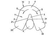
図5aには、本発明によるガスバッグ1の膨張状態が示されている。このガスバッグ1の包体10は、前記した実施の形態によるガスバッグ包体と同一の構成である。特に図5aの立面図において、ガスバッグ包体10は、開かれた実質的に逆U字状の形状とされている。この結果、ガスバッグは、間隙5によって互いに離間している2つのガスバッグ部2,3を形成するとともに、自由端部20,30および二つの部分2、3間における連結部4を有することとなる。
【0038】
2つのガスバッグ部を互いに対して拘束するために、ガスバッグ1は、更なる被覆材7によって囲まれている。この被覆材7は、ガスバッグ1の2つの部分2,3を囲み、スロット5を形成する側壁部21,31でスロット5の部分において二部分2,3を互いに押圧する。カットパターン70で作られた被覆材7は、前端部71と後端部72が開口し、ガスバッグ部2,3の端部20,30と連結部4が被覆材7から突出している。
【0039】
さらに被覆材7は、スロット5の部分にガセット73を有し、被覆材の開口前側部71に、2つのガスバッグ部2,3の前端部20,30それぞれのための2つの別個の開口部が形成されている。
【0040】
ガスバッグ1に対して被覆材7を特定の位置に位置決めするために、被覆材7を、例えばガスバッグ部2,3の前端部20,30の部分と、ガスバッグ1の連結部4で(例えば、接着剤で接着し、あるいは縫着することで)固定してもよい。この場合、被覆材7とガスバッグ部2,3の自由端部20,30との間の接続箇所は着脱自在とする。
【0041】
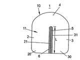
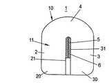
図5aは、被覆材7を有するガスバッグ1の立面図であり、平らに広げた空のガスバッグ(すなわち、ガスバッグを被覆材とともに畳んでハウジング内に収納可能なパックを形成する前の状態)と、障害なく膨張(展開)したガスバッグ1の両方を示す。
【0042】
ガスバッグが障害を受けることなく膨張する(ガスバッグの展開時にOOPの状態にあるかがみ込んだ乗員との早期衝突がない)と、2つのガスバッグ部2,3間のスロット5がほとんど塞がるように、2つのガスバッグ部2、3が被覆材7によって相互に拘束される。すなわちガスバッグ部2,3の2つの内側壁部21,31が被覆材7によって相互に押しつけられると同時に、被覆材7が間隙5をカバーする。
【0043】
一方、乗員がガスバッグの膨張時にOOPの状態にあって、ガスバッグの展開時に、既に乗員の身体部(頭部K)がガスバッグ1の間隙5内を押し進んでいると、これによって被覆材7とガスバッグ部2,3の自由端部20,30との間の接続が解除される。これは、頭部Kがガスバッグ1の間隙5内に進入する際の力によるものである。
【0044】
さらに頭部Kがガスバッグ1の間隙5内に進入することによって、被覆材7が、ガスバッグ1の展開時に、ガスバッグ部2,3の端部20,30に対して一層後方に変位するか、あるいはガスバッグ1とともに広がらないように構成され、頭部Kが更に間隙5内深くに進入可能となる。同時に、2つのガスバッグ部2、3が外側に押し離される。このように乗員の頭部Kが間隙5内に侵入することによって、OOPの場合にケガをする危険が相当減少する。
【0045】
図6aには、図5aのガスバッグの変更例が示されている。別のガスバッグ部(位置決め部74)が、被覆材7の前端部71の位置決めの補助のため、間隙5の部分に形成されている。
【0046】
被覆材7の前端部71は位置決め部74に接続されている。従って、ガスバッグ1の膨張時に、被覆材7の前端部71は、ガスバッグ部2,3の自由端部20,30の部分に位置する。さらに被覆材7は、後端部72でガスバッグ1の連結部4に接続されていることが好ましい。
【0047】
従って、図6aによるガスバッグは、平らに広げた空の状態の被覆材7を有するガスバッグ1のみならず、ガスバッグ1が障害なく膨張した状態も示している。これは、ガスバッグ部2,3の端部20,30箇所に位置する被覆材7の前端部71を、位置決め部74で固定するとともに、後端部72でガスバッグ1の連結部4に固定することにより、ガスバッグ1の膨張時に、被覆材7は、2つのガスバッグ部2,3を囲む、前記接続箇所によって固定された位置を維持するからである。
【0048】
ガスバッグ1の膨張状態では、ガスバッグ部2,3は、被覆材7によって相互に拘束され、その結果、間隙5が実質的に塞がれ、間隙のないガスバッグと同じ保護機能を果たす。
【0049】
一方、ガスバッグの膨張時に乗員がOOPの状態にあって、ガスバッグの方向に屈んでいる場合、ガスバッグの展開時に、乗員の頭部Kがガスバッグ1のスロット5内を押し進むことができる。その結果、乗員は、ガスバッグ1の位置決め部74の展開膨張を阻止する。従って、ガスは、側方の2つのガスバッグ部2、3内にのみ流入する。
【0050】
間隙5内に延出形成されている位置決め部74が膨張しないため、被覆材7は、頭部Kが間隙5内に進入する際、後方の連結部4の方向に一層変位するか、または、ガスバッグ1とともに広がらないようにされることが可能である。同時に、2つのガスバッグ部2,3が側方外側に押し離される。これによって、頭部Kが更に間隙5内に進入することが可能となり、その分、OOPにおけるケガの危険性が減る。
【0051】
図7aおよび図7bには、図5aに係る実施の形態の、他の変更例が示されている。ガスバッグ1の被覆材7の前端部71が閉口していて、ガスバッグ部2、3の自由端部20、30は、被覆材7の前端部71を突き抜けることができない。その代わりに、図7aおよび図7bの被覆材7は、側壁部76、77に開口部を有し、ガスバッグ部2,3が、その開口部から外側に突出することが可能とされている(図7c)。これは、図7bに示されているように、被覆材7の底部生地部79aと上部生地部79bが比較的狭いウェブ78のみを介して横方向に連結されているからである。従って開口部は、被覆材7の側壁部76,77に形成されており、その開口部からガスバッグ1の2つの部分2,3が突出することが可能とされる。
【0052】
上述の実施の形態と同様、図7aは、平らに広げた空のガスバッグと、障害なく膨張したガスバッグ1の双方を示す。一方、対応する図7bの側面図は、ガスバッグ1が被覆材7の底部79aと上部79bとの間に収容されている、ガスバッグ1の膨張状態のみを示している。
【0053】
被覆材7(横方向の連結ウェブ78を考慮に入れた)が、ガスバッグ1、特にガスバッグ部2,3をリング状に囲むので、この形態においても、2つのガスバッグ部2,3を相互に拘束することが可能である。
【0054】
しかしながら、ガスバッグ1の膨張時に、乗員がガスバッグ1の方向に相当屈んでいる場合、乗員は、ガスバッグの展開時にガスバッグ1の間隙5の方向に進入し、2つのガスバッグ部2,3が外側に押し離される。この時、ガスバッグ部2,3は、被覆材7の側壁部76,77の開口部を突き抜けることが可能である。その結果、被覆材7が、ガスバッグ部2,3の連結部4の方向へと後方にずれるか、あるいは広がらないように構成され、乗員の頭部Kが間隙5内に一層進入することができる。これによって頭部Kが間隙5内に深く進入することが可能となり、OOPの場合に、乗員の頭部Kとガスバッグ1との激しい衝突が回避可能とされる。
【0055】
本発明のガスバッグの構成は、特にドライバーと助手席乗員のエアバッグモジュールに適しているが、サイドエアバッグなどのエアバッグに用いてもよい。
【図面の簡単な説明】
【図1a】 間隙によって離間している2つのガスバッグ部を有する広げられた空のガスバッグが示されている。
【図1b】 図1aに示されているガスバッグの流入ガスによる膨張時の状態を示している。
【図2a】 2つのガスバッグ部を有するガスバッグの第2の実施の形態を示す立面図であり、2つのガスバッグ部の間の間隙に平面部材が渡されている。
【図2b】 図2aに示されているガスバッグの正面図である。
【図2c】 膨張時の図2aおよび図2bのガスバッグを示す。この図では、乗員の身体部分が2つのガスバッグ部間の間隙内に入り込んでいる。
【図2d】 膨張時の図2aおよび図2bのガスバッグを示す。この図では、乗員の身体部分が2つのガスバッグ部間の間隙内に入り込んでいる。
【図3a】 図2aのガスバッグの変更例を示し、平面部材が2つのガスバッグ部間の間隙の一部分にのみ渡されている。
【図3b】 膨張時の図3aのガスバッグを示し、乗員の身体部分が2つのガスバッグ部間の間隙内に入り込んでいる。
【図4】 2つのガスバッグ部間の間隙内に入り込んだ乗員の側面図である。
【図5a】 図2aのガスバッグの変更例を示し、2つのガスバッグ部が、被覆材によって囲まれて互いに対して拘束されている。
【図5b】 膨張時の図5aのガスバッグを示し、乗員の身体部分が2つのガスバッグ部間の間隙内に入り込んでいる。
【図6a】 図5aのガスバッグの変更例を示し、ガスバッグが、間隙内に被覆材の位置決めのための補助として別のガスバッグ部を有している。
【図6b】図6bは、膨張時の図6aのガスバッグを示し、乗員の身体部分が2つのガスバッグ部間の間隙内に入り込んでいる。
【図7a】 図5aのガスバッグの変更例を示し、ガスバッグの被覆材が、側部に開口部を有し、2つのガスバッグ部が、OOPの場合に開口部から突き出ることが可能である。
【図7b】 図7aのガスバッグの側面図である。
【図7c】 膨張時の図7aおよび図7bのガスバッグを示し、乗員の身体部分が2つのガスバッグ部間の間隙内に入り込んでいる。[0001]
[Field of the Invention]
The present invention relates to a gas bag for an occupant protection device for an automobile according to the preamble of
[0002]
[Prior art]
Such a gas bag can be inflated by using a gas generator, and in the inflated state, a gas-filled cushion is formed to protect an occupant from being injured during a collision. For this purpose, a gas bag or an airbag module including a gas bag is provided in an automobile such that a gas bag package has a package surface that faces an occupant in the inflated state of the gas bag and that the occupant collides with in the event of a collision. It has been.
[0003]
However, if the occupant is in a position other than the normal seating position when the gas bag is inflated (this case is referred to as “OOP” in this specification), the occupant may be injured by the deployment of the gas bag during the inflation. There is sex. Therefore, various proposals have been made so far in order to prevent the passenger from being injured by the gas bag that is deployed. According to one proposal, a sensor is provided to detect an abnormal seating position of the occupant and, if necessary, prevent the airbag module from operating and prevent the gas bag from inflating and deploying. Another known solution is to use a multi-stage gas generator to inflate the gas bag, so that the gas bag is initially relatively low in the first stage to prevent injury to the occupant. It expands only to internal pressure.
[0004]
DE 19749914A1 discloses a device for impact protection provided on the steering wheel of a motor vehicle. This device has a gas bag with a filling device for inflating the gas bag, the shape of the entire gas bag at the time of filling is a ring shape, and a conical or funnel shape on the front surface facing the driver of the gas bag With a recess. This is intended to reduce occupant impact in the case of OOP.
[0005]
DE 19757410A1 is a gas bag for an air bag module having a gas bag portion, which is separated, moves independently of other gas bags, and is located within the outer shape of the gas bag. The gas bag portion can follow the movement of the occupant when a collision occurs.
[0006]
[Patent Document 1]
German Patent Application Publication No. 19749914A1
[Patent Document 2]
German Patent Application Publication No. 19574410A1
[0007]
[Problems to be solved by the invention]
The object of the present invention is to improve the gas bag of the type described at the beginning and to minimize the risk of injury to the passenger when the gas bag is inflated when the passenger is in a position other than the normal seating position when the gas bag is inflated. It is to reduce.
[0008]
[Means for Solving the Problems]
This problem is solved by providing a gas bag having the features of
[0009]
According to the present invention, in the inflated state, the gas bag enclosure forms a gap connected to the gas bag enclosure surface corresponding to the occupant, and in the case of OOP, the occupant (gas The body part facing the bag) can enter the gap, in which case the gap is widened so that in the case of OOP, the bag surface and the occupant directly facing the occupant It is made not to collide.
[0010]
In this case, the “wrapping surface” of the gas bag corresponding to or facing the occupant is the portion of the gas bag wrapping that is brought into contact with the occupant that hits the gas bag in the event of a collision. is there. Therefore, this package surface is a portion of the gas bag package into which the occupant thrusts in the event of a collision. In this case, the package surface facing the occupant may be formed in particular by the curved portion of the package of the gas bag.
[0011]
The gap according to the present invention, which is connected to the relevant part of the gas bag enclosure and can be fitted by the occupant in the case of OOP, is such that when the gas bag is deployed, the wrapping surface of the gas bag corresponding to the occupant This is to prevent damage. The body part of the occupant facing this packaging surface fits into the gap according to the invention, so that a direct collision with the gas bag outer packaging is avoided.
[0012]
In a preferred embodiment of the present invention, a gas bag that forms a gap along opposing longitudinal sides to prevent an occupant's body part from fitting into the gap after the gas bag is fully inflated. These two parts are constrained relative to each other to close the gap after the gas bag is inflated. Accordingly, in the inflated state, a pressure is applied to the two portions of the gas bag so as to try to contact each other along the gap. This is intended so that the package surface of the gas bag facing the occupant in the fully inflated state can perform the same function as a gas bag without a gap as much as possible.
[0013]
It is preferable that the gap extends from the package surface corresponding to the occupant in the direction of the other side far from the package surface of the gas bag.
[0014]
The length of the gap in one direction corresponds to the length of the gas bag in the same direction, and the gas bag is divided into two parts by the gap.
[0015]
In this case, the gas bag is preferably formed to have an open shape, particularly a U-shape that surrounds the gap. In this way, the body part of the occupant is much easier to enter into the gap than a gas bag having a completely closed shape as described in DE 19749914A1.
[0016]
According to a variant of the invention, the cut pattern forming the gas bag envelope is selected so that the two parts of the gas bag are constrained relative to each other due to the shape of the gas bag envelope. . Therefore, if no body part of the occupant has entered the gap when the gas bag is inflated, the two parts of the gas bag are in contact with each other in a state in which pressure is applied after the gas bag is inflated. In addition, the shape of the gas bag envelope is selected.
[0017]
Here, when the gas bag is inflated and deployed, the two parts of the gas bag are first filled with gas using a gas generator so as to be separated from each other along the gap. As a result, the gap is already large enough to allow the occupant's body part to enter when the gas bag is inflated (in the case of OOP) at the initial stage. Thereafter, when the gas bag is substantially fully inflated, i.e. when the incoming gas does not affect the position of the two parts of the gas bag, the position of the two gas bag parts depends on the shape of the gas bag envelope. It will be decided considerably. Therefore, by appropriately selecting the shape of the package or the shape of the cut pattern forming the package, it is ensured that the two portions of the gas bag are in contact with each other to narrow the gap when the gas bag is inflated. It is possible to
[0018]
According to another variant of the invention, additional means are provided for restraining the two parts of the gas bag together so that the two parts of the gas bag can abut each other after the gas bag has been inflated. .
[0019]
Additional means for constraining the two parts of the gas bag may be formed by a planar member that is at least partially passed to the gap and that constrains the two parts of the gas bag along the gap. .
[0020]
According to another embodiment of the invention, the means for constraining the two parts of the gas bag are made in a separate cut pattern that surrounds and constrains the two parts of the gas bag relative to each other (gas It is made of a covering material (not made of bag fabric). When the gas bag is deployed without hindrance (ie, when the occupant is not in an OOP state and does not enter the gap early when the gas bag is inflated), the covering material is applied to the gas bag so as to at least partially cover the gap. It is preferable that they are arranged.
[0021]
In addition, when the gas bag is inflated (due to the OOP condition), the body part of the occupant is pushed forward in the direction of the gap so that the gap gradually widens and the body part of the occupant can enter the gap. Further, the covering material is configured and arranged so as to be displaceable with respect to the gas bag. In this case, the relative displacement of the covering material with respect to the gas bag is independent of whether the covering material or the gas bag actually moves relative to the fixed coordinate system (of the car body). Means that they move relative to each other. In particular, the case where the covering material cannot be deployed together with the gas bag by the body part of the occupant pushing the gap is included.
[0022]
In order to fix the position of the dressing relative to the gas bag, the dressing can be connected to the gas bag at at least one connection point. In this case, especially when the gas bag is inflated, the body part of the occupant is released into the gap, so that the connection is released. You may make it connect with a bag so that attachment or detachment is possible.
[0023]
Furthermore, the dressing preferably has at least one opening through which the gas bag portion can protrude. This is intended to ensure that the gas bag is fully deployed when inflated.
[0024]
An automobile occupant protection device having a gas bag according to the invention is characterized by the structure of
[0025]
Further features and advantages of the present invention will become apparent from the following description of embodiments with reference to the drawings.
[0026]
DETAILED DESCRIPTION OF THE INVENTION
In FIGS. 1a and 1b, reference examples are provided to help technical understanding of the present invention.
FIG. 1a shows an empty gas bag laid out flat. The gas bag is composed of two
[0027]
FIG. 1 b shows a state in which the
[0028]
In FIG. 1 b, the passenger's head K is shown between the two
[0029]
Further, when the occupant is in a normal seating position when the air bag module is activated and the
[0030]
FIG. 2a shows a modification of the gas bag of FIG. 1b in an inflated state. Also in the present embodiment according to FIG. 2a, the
[0031]
As can be seen from the front view of FIG. 2 b, the
[0032]
In this case, the cloth or net 6 extends over the entire length L of the gap 5 (the length in the direction intersecting the width B of the gas bag 1) (see FIG. 2a) or shown in FIG. 3a. As in the modified example, the
[0033]
The
[0034]
2c and 2d are the gas bags of FIGS. 2a and 2b, when the vehicle is considerably decelerated and the airbag module including the
[0035]
In FIG. 3b, the occupant's head K is shown when the
[0036]
FIG. 4 shows an occupant I of an automobile, particularly a front seat occupant who was in a position close to the
[0037]
FIG. 5a shows the inflated state of the
[0038]
In order to constrain the two gas bag parts relative to each other, the
[0039]
Furthermore, the
[0040]
In order to position the covering
[0041]
FIG. 5 a shows a
[0042]
When the gas bag is inflated without being obstructed (there is no early collision with an occupant in a state of OOP when the gas bag is deployed), the
[0043]
On the other hand, if the occupant is in the OOP state when the gas bag is inflated, and the gas bag is deployed, the occupant's body part (head K) has already been pushed through the
[0044]
Further, when the head K enters the
[0045]
FIG. 6a shows a modification of the gas bag of FIG. 5a. Another gas bag portion (positioning portion 74) is formed in the
[0046]
The
[0047]
Therefore, the gas bag according to FIG. 6a shows not only the
[0048]
In the expanded state of the
[0049]
On the other hand, if the occupant is in an OOP state when the gas bag is inflated and bends in the direction of the gas bag, the occupant's head K may push forward in the
[0050]
Since the
[0051]
FIGS. 7a and 7b show another modification of the embodiment according to FIG. 5a. The
[0052]
Similar to the embodiment described above, FIG. 7a shows both an empty gas bag laid flat and a
[0053]
Since the covering material 7 (taking into account the connecting
[0054]
However, when the occupant is considerably bent in the direction of the
[0055]
The configuration of the gas bag of the present invention is particularly suitable for an airbag module for drivers and passengers, but may be used for an airbag such as a side airbag.
[Brief description of the drawings]
FIG. 1a shows an unfolded empty gas bag having two gas bag portions separated by a gap.
FIG. 1b shows a state when the gas bag shown in FIG. 1a is inflated by an inflow gas.
FIG. 2a shows a second embodiment of a gas bag having two gas bag portions.StandingIt is a top view and the planar member is passed to the clearance gap between two gas bag parts.
2b is a front view of the gas bag shown in FIG. 2a.
FIG. 2c shows the gas bag of FIGS. 2a and 2b when inflated. In this figure, the body part of the occupant has entered the gap between the two gas bag portions.
FIG. 2d shows the gas bag of FIGS. 2a and 2b when inflated. In this figure, the body part of the occupant has entered the gap between the two gas bag portions.
FIG. 3a shows a modification of the gas bag of FIG. 2a, in which the planar member is passed only over a portion of the gap between the two gas bag portions.
FIG. 3b shows the gas bag of FIG. 3a when inflated, with the occupant's body part entering the gap between the two gas bag parts.
FIG. 4 is a side view of an occupant entering a gap between two gas bag portions.
FIG. 5a shows a modification of the gas bag of FIG. 2a in which two gas bag portions are surrounded by a covering material and are restrained with respect to each other.
FIG. 5b shows the gas bag of FIG. 5a when inflated, with the occupant's body part entering the gap between the two gas bag parts.
6a shows a modification of the gas bag of FIG. 5a, the gas bag having another gas bag part as an aid for positioning the covering in the gap.
FIG. 6b shows the gas bag of FIG. 6a when inflated, with the occupant's body part entering the gap between the two gas bag parts.
FIG. 7a shows a modification of the gas bag of FIG. 5a, in which the gas bag covering material has an opening on the side and the two gas bag parts can protrude from the opening in the case of OOP. is there.
7b is a side view of the gas bag of FIG. 7a.
FIG. 7c shows the gas bag of FIGS. 7a and 7b when inflated, with the occupant's body part entering the gap between the two gas bag parts.
Claims (11)
Translated fromJapaneseガスバッグ(1)は、連結部(4)を介して互いに連結されている2つの部分(2、3)によって立面視において実質的に逆U字形の形状とされるとともに、ガスバッグ(1)の膨張時に前記2つの部分(2、3)間に形成される間隙(5)と、前記間隙(5)によって互いに離間する前記2つの部分(2、3)の自由端(20、30)側から前記連結部(4)側へと保護する乗員に面する包体面(11)を有する構成であり、
前記2つの部分(2、3)が、前記間隙(5)を渡す平面部材(6)によって互いに連結され、これにより膨張が完了したガスバッグ(1)の前記間隙(5)を狭めるように相互に拘束される構成であり、
また前記平面部材(6)が前記間隙(5)の全長(L)の一部分にのみ渡されていることを特徴とするガスバッグ。A gas bag for an occupant protection device for a motor vehicle that is inflatable using a gas generator, wherein the wrapping body has a wrapping surface corresponding to the occupant to be protected,
The gas bag (1)has a substantiallyinverted U-shape when viewed in elevation by two portions (2, 3) connected to each other via a connecting portion (4). ) And afree end (20, 30) of the two parts (2, 3) separated from each other by the gap (5). It is a configuration having apackaging surface (11) facing the occupant protecting from the side to the connecting portion (4) side ,
The two parts (2, 3) are connected to each other by a flat member (6) that passes the gap (5), thereby narrowing the gap (5) of the gas bag (1) that has been inflated. Is constrained by
Further, the gas bag is characterized in that the planar member (6) is passed over only a part of the entire length (L) of the gap (5).
ガスバッグ(1)は、連結部(4)を介して互いに連結されている2つの部分(2、3)によって立面視において実質的に逆U字形の形状とされるとともに、ガスバッグ(1)の膨張時に前記2つの部分(2、3)間に形成される間隙(5)と、前記間隙(5)によって互いに離間する前記2つの部分(2、3)の自由端(20、30)側から前記連結部(4)側へと保護する乗員に面する包体面(11)を有する構成であり、
前記2つの部分(2、3)を互いに対して拘束するために、更に前記2つの部分(2、3)を囲む被覆材(7)が設けられていることを特徴とするガスバッグ。A gas bag for an occupant protection device for a motor vehicle that is inflatable using a gas generator, wherein the wrapping body has a wrapping surface corresponding to the occupant to be protected,
The gas bag (1) has a substantially inverted U-shape when viewed in elevation by two portions (2, 3) connected to each other via a connecting portion (4). ) And a free end (20, 30) of the two parts (2, 3) separated from each other by the gap (5). It has a structure having a packaging surface (11) facing an occupant protecting from the side to the connecting portion (4) side,
It said two parts in order to restrain the (2,3) relative to each other, further wherein the two parts (2, 3) surrounding the covering material (7), wherein a toRuga Subaggu that is provided.
Applications Claiming Priority (2)
| Application Number | Priority Date | Filing Date | Title |
|---|---|---|---|
| DE10033937ADE10033937C2 (en) | 2000-07-05 | 2000-07-05 | Airbag for an occupant protection device |
| PCT/DE2001/002532WO2002002376A1 (en) | 2000-07-05 | 2001-07-05 | Gas bag for a passenger protection device |
Publications (2)
| Publication Number | Publication Date |
|---|---|
| JP2004502585A JP2004502585A (en) | 2004-01-29 |
| JP4119242B2true JP4119242B2 (en) | 2008-07-16 |
Family
ID=7648721
Family Applications (1)
| Application Number | Title | Priority Date | Filing Date |
|---|---|---|---|
| JP2002507649AExpired - Fee RelatedJP4119242B2 (en) | 2000-07-05 | 2001-07-05 | Gas bag for occupant protection device |
Country Status (7)
| Country | Link |
|---|---|
| US (1) | US7137647B2 (en) |
| EP (1) | EP1296857B1 (en) |
| JP (1) | JP4119242B2 (en) |
| BR (1) | BR0112198A (en) |
| DE (3) | DE10033937C2 (en) |
| ES (1) | ES2248363T3 (en) |
| WO (1) | WO2002002376A1 (en) |
Families Citing this family (55)
| Publication number | Priority date | Publication date | Assignee | Title |
|---|---|---|---|---|
| US20060028009A1 (en)* | 2002-05-22 | 2006-02-09 | Takata Corporation | Airbag device |
| JP4274742B2 (en)* | 2002-05-22 | 2009-06-10 | タカタ株式会社 | Air bag and air bag device |
| DE10224138A1 (en)* | 2002-05-24 | 2003-12-11 | Takata Petri Ag | Driver or front passenger airbag |
| US6834886B2 (en)* | 2003-02-18 | 2004-12-28 | Takata Corporation | Airbag device |
| JP4622386B2 (en)* | 2004-08-24 | 2011-02-02 | タカタ株式会社 | Air bag and air bag device |
| US20050098994A1 (en)* | 2003-11-07 | 2005-05-12 | Takata Corporation | Airbag cushion with angled recess |
| JP4321228B2 (en) | 2003-11-14 | 2009-08-26 | タカタ株式会社 | Air bag and air bag device |
| JP2005239128A (en)* | 2004-02-24 | 2005-09-08 | Takata Corp | Twin air bag device |
| JP2006051884A (en)* | 2004-08-11 | 2006-02-23 | Autoliv Development Ab | Airbag device |
| JP4654645B2 (en)* | 2004-09-24 | 2011-03-23 | タカタ株式会社 | Air bag and air bag device |
| JP2006117235A (en) | 2004-10-21 | 2006-05-11 | Takata Corp | Airbag device |
| JP4449734B2 (en)* | 2004-12-16 | 2010-04-14 | タカタ株式会社 | Air bag and air bag device |
| JP4659484B2 (en)* | 2005-02-25 | 2011-03-30 | 日本プラスト株式会社 | Airbag |
| JP4645280B2 (en)* | 2005-04-18 | 2011-03-09 | 日産自動車株式会社 | Occupant protection device and method |
| JP2006321313A (en)* | 2005-05-18 | 2006-11-30 | Mazda Motor Corp | Vehicular air bag device |
| US7350807B2 (en) | 2005-05-25 | 2008-04-01 | Autoliv Asp, Inc. | Divided airbag system |
| JP4235975B2 (en) | 2005-06-10 | 2009-03-11 | オートリブ ディベロップメント エービー | Airbag device and airbag manufacturing method |
| JP4760158B2 (en)* | 2005-06-24 | 2011-08-31 | タカタ株式会社 | Air bag and air bag device |
| DE102006011058A1 (en) | 2005-08-25 | 2007-03-15 | Takata-Petri Ag | Driver or passenger airbag module with a gas bag |
| US7625008B2 (en)* | 2005-10-17 | 2009-12-01 | Key Safety Systems, Inc. | Air bag with groove or recess, open or partially covered |
| US7152880B1 (en) | 2005-10-17 | 2006-12-26 | Key Safety Systems, Inc. | Grooved air bag |
| US7484757B2 (en) | 2005-12-08 | 2009-02-03 | Gm Global Technology Operations, Inc. | Air bag with a supported channel |
| US7980592B2 (en)* | 2006-05-11 | 2011-07-19 | Trw Vehicle Safety Systems Inc. | Bi-lobular air bag |
| JP5128836B2 (en)* | 2007-03-20 | 2013-01-23 | オートリブ ディベロップメント エービー | Vehicle airbag |
| JP2009061867A (en) | 2007-09-05 | 2009-03-26 | Toyoda Gosei Co Ltd | Air bag for front passenger seat |
| EP2072346A1 (en)* | 2007-12-19 | 2009-06-24 | Dalphi Metal Espana, S.A. | Optimised airbag module |
| JP4995070B2 (en)* | 2007-12-28 | 2012-08-08 | 日本プラスト株式会社 | Knee airbag device |
| US7946619B2 (en)* | 2008-01-31 | 2011-05-24 | Tk Holdings Inc. | Airbag |
| US7695012B2 (en)* | 2008-04-03 | 2010-04-13 | Autoliv Asp, Inc. | Airbag systems with a split pocket |
| US7862073B2 (en) | 2008-06-05 | 2011-01-04 | Gm Global Technology Operations, Inc. | Split top air bag assembly |
| JP5426903B2 (en)* | 2009-03-02 | 2014-02-26 | オートリブ ディベロップメント エービー | Airbag device |
| US7938445B2 (en)* | 2009-03-03 | 2011-05-10 | Autoliv Asp, Inc. | Dual chamber airbag cushions with a safety vent in the front chamber |
| US7946613B2 (en) | 2009-03-03 | 2011-05-24 | Autoliv Asp, Inc. | Dual chamber airbag cushion |
| JP2011063112A (en)* | 2009-09-17 | 2011-03-31 | Nippon Plast Co Ltd | Airbag device |
| US8371612B2 (en) | 2009-09-17 | 2013-02-12 | Autoliv Asp, Inc. | Inflatable airbag assemblies with lateral and longitudinal tethers |
| DE102010004528B4 (en) | 2010-01-14 | 2018-07-19 | Autoliv Development Ab | An air bag assembly |
| JP5582834B2 (en)* | 2010-03-19 | 2014-09-03 | 日本プラスト株式会社 | Airbag device |
| KR101219694B1 (en)* | 2010-08-30 | 2013-01-18 | 현대자동차주식회사 | Airbag apparatus for vehicle |
| US8657334B2 (en) | 2011-02-11 | 2014-02-25 | Key Safety Systems, Inc. | Airbag cushion |
| JP5738332B2 (en)* | 2013-02-08 | 2015-06-24 | オートリブ ディベロップメント エービー | Airbag device |
| US9340176B2 (en) | 2014-03-13 | 2016-05-17 | Ford Global Technologies, Llc | Passenger airbag with secondary chamber |
| US9150186B1 (en)* | 2014-03-13 | 2015-10-06 | Ford Global Technologies, Llc | Passenger airbag with secondary chamber |
| US9707921B2 (en)* | 2014-10-21 | 2017-07-18 | Trw Vehicle Safety Systems Inc. | Self-conforming rearseat air bag |
| CN107107857B (en) | 2014-12-24 | 2020-02-18 | Tk控股公司 | Side impact airbag module |
| JP2016132410A (en)* | 2015-01-21 | 2016-07-25 | 豊田合成株式会社 | Vehicle external airbag device |
| JP6390596B2 (en)* | 2015-11-18 | 2018-09-19 | トヨタ自動車株式会社 | Airbag device |
| US10046726B2 (en)* | 2016-02-16 | 2018-08-14 | Allied Treasure Inc, Limited | Airbag safety system for a two-wheeled vehicle |
| US10343641B2 (en) | 2017-04-17 | 2019-07-09 | Ford Global Technologies, Llc | Vehicle airbag |
| JP6709263B2 (en) | 2018-09-28 | 2020-06-10 | 株式会社Subaru | Occupant protection device |
| JP6703580B2 (en)* | 2018-09-28 | 2020-06-03 | 株式会社Subaru | Occupant protection device |
| JP6603773B1 (en) | 2018-09-28 | 2019-11-06 | 株式会社Subaru | Crew protection device |
| JP6757382B2 (en) | 2018-09-28 | 2020-09-16 | 株式会社Subaru | Crew protection device |
| CN111688623A (en)* | 2019-03-12 | 2020-09-22 | 本田技研工业株式会社 | Airbag and occupant restraint device |
| CN110843714B (en)* | 2019-11-15 | 2020-11-24 | 江苏理工学院 | A kind of delayed detonation of automobile airbag and control method thereof |
| DE102023132907A1 (en)* | 2023-11-24 | 2025-05-28 | Global Safety Textiles Gmbh | Airbag, preferably OPW airbag, for a vehicle |
Family Cites Families (17)
| Publication number | Priority date | Publication date | Assignee | Title |
|---|---|---|---|---|
| US3588142A (en)* | 1968-09-09 | 1971-06-28 | John F Gorman | Vehicle safety device |
| DE3630685C2 (en)* | 1986-07-22 | 1994-03-10 | Trw Repa Gmbh | Gas cushion impact protection device for a motor vehicle occupant |
| DE4010767A1 (en)* | 1990-04-04 | 1991-10-10 | Daimler Benz Ag | IMPACT PROTECTION DEVICE FOR A PASSENGER OF A MOTOR VEHICLE |
| US5190313A (en)* | 1991-08-07 | 1993-03-02 | Robert Hickling | Impact cushioning device |
| JP2900098B2 (en)* | 1991-12-27 | 1999-06-02 | 日産自動車株式会社 | Automotive airbag device |
| US5308113A (en)* | 1992-10-09 | 1994-05-03 | Trw Vehicle Safety Systems Inc. | Airbag inflation-controlling member |
| US5480184A (en)* | 1994-03-23 | 1996-01-02 | Young; William A. | Inflatable occupant restraint device |
| JPH07285408A (en)* | 1994-04-21 | 1995-10-31 | Toyota Motor Corp | Airbag device |
| WO1997034783A1 (en)* | 1996-03-19 | 1997-09-25 | Milliken Research Corporation | Toroidal air bag assembly |
| JP3035691U (en)* | 1996-09-12 | 1997-03-28 | 桂司 古川 | Air bag for automobile |
| JP3878220B2 (en)* | 1996-09-30 | 2007-02-07 | 日本プラスト株式会社 | Airbag device |
| JPH10166981A (en)* | 1996-12-13 | 1998-06-23 | Ikeda Bussan Co Ltd | Air bag main body of air bag device |
| DE19747410A1 (en) | 1997-10-27 | 1999-04-29 | Siemens Ag | Method for synchronising synchronous drive EMF with current space vector using digital field orientation |
| DE19749914C2 (en)* | 1997-11-11 | 2001-05-23 | Hs Tech & Design | Airbag device which is housed in the steering wheel of a motor vehicle |
| DE19757410C2 (en)* | 1997-12-15 | 2001-01-25 | Petri Ag | Airbag for an airbag module |
| US6059311A (en)* | 1998-02-21 | 2000-05-09 | Breed Automotive Technology, Inc. | Pillar-mounted side impact and rollover air bag |
| DE19930157B4 (en)* | 1999-06-30 | 2012-10-31 | TAKATA Aktiengesellschaft | Airbag for a motor vehicle |
- 2000
- 2000-07-05DEDE10033937Apatent/DE10033937C2/ennot_activeExpired - Fee Related
- 2001
- 2001-07-05BRBR0112198-7Apatent/BR0112198A/ennot_activeIP Right Cessation
- 2001-07-05ESES01955229Tpatent/ES2248363T3/ennot_activeExpired - Lifetime
- 2001-07-05WOPCT/DE2001/002532patent/WO2002002376A1/enactiveIP Right Grant
- 2001-07-05DEDE50107436Tpatent/DE50107436D1/ennot_activeExpired - Lifetime
- 2001-07-05DEDE10193245Tpatent/DE10193245D2/ennot_activeExpired - Fee Related
- 2001-07-05JPJP2002507649Apatent/JP4119242B2/ennot_activeExpired - Fee Related
- 2001-07-05EPEP01955229Apatent/EP1296857B1/ennot_activeExpired - Lifetime
- 2003
- 2003-01-06USUS10/336,836patent/US7137647B2/ennot_activeExpired - Fee Related
Also Published As
| Publication number | Publication date |
|---|---|
| BR0112198A (en) | 2003-07-01 |
| EP1296857A1 (en) | 2003-04-02 |
| DE10033937A1 (en) | 2002-01-24 |
| DE10193245D2 (en) | 2003-07-17 |
| ES2248363T3 (en) | 2006-03-16 |
| EP1296857B1 (en) | 2005-09-14 |
| JP2004502585A (en) | 2004-01-29 |
| DE10033937C2 (en) | 2002-09-26 |
| US7137647B2 (en) | 2006-11-21 |
| US20040232681A1 (en) | 2004-11-25 |
| WO2002002376A1 (en) | 2002-01-10 |
| DE50107436D1 (en) | 2005-10-20 |
Similar Documents
| Publication | Publication Date | Title |
|---|---|---|
| JP4119242B2 (en) | Gas bag for occupant protection device | |
| EP1338478B1 (en) | Passenger protecting device | |
| CN109153363B (en) | side air bag device | |
| JP2960359B2 (en) | Gas bag protector against lateral impact | |
| JP2769424B2 (en) | Automotive inflatable gas bag | |
| JP3773088B2 (en) | Automotive airbag equipment | |
| KR20190028588A (en) | Air bag device for vehicle | |
| EP1479571B1 (en) | Occupant leg protection apparatus | |
| JP2011527965A (en) | Vehicle seat device and airbag device for automobile, and vehicle occupant protection method | |
| JP2011527965A5 (en) | ||
| JP7290748B2 (en) | side airbag device | |
| WO1997042061A1 (en) | Air bag with externally mounted tether | |
| JP2005297917A (en) | Vehicle occupant restraint system | |
| JP2007230395A (en) | Airbag and airbag device | |
| JP2009505876A (en) | Driver or passenger airbag module having an airbag | |
| WO2007099668A1 (en) | Airbag and airbag device | |
| CN115195657B (en) | Occupant protection device | |
| JP7223621B2 (en) | Airbag | |
| KR20240154018A (en) | Restraint devices, restraint assemblies and seat units | |
| JP4103633B2 (en) | Side airbag device | |
| JP4569310B2 (en) | Knee airbag device for vehicle | |
| JPH1148889A (en) | Air bag | |
| JP3539312B2 (en) | Vehicle occupant protection system | |
| KR20150022257A (en) | Air-bag apparatus for vehicles | |
| JPH05208648A (en) | Protecting device for vehicle occupant |
Legal Events
| Date | Code | Title | Description |
|---|---|---|---|
| A621 | Written request for application examination | Free format text:JAPANESE INTERMEDIATE CODE: A621 Effective date:20040512 | |
| A131 | Notification of reasons for refusal | Free format text:JAPANESE INTERMEDIATE CODE: A131 Effective date:20060512 | |
| A977 | Report on retrieval | Free format text:JAPANESE INTERMEDIATE CODE: A971007 Effective date:20060517 | |
| A601 | Written request for extension of time | Free format text:JAPANESE INTERMEDIATE CODE: A601 Effective date:20060811 | |
| A602 | Written permission of extension of time | Free format text:JAPANESE INTERMEDIATE CODE: A602 Effective date:20060818 | |
| A521 | Request for written amendment filed | Free format text:JAPANESE INTERMEDIATE CODE: A523 Effective date:20061110 | |
| A131 | Notification of reasons for refusal | Free format text:JAPANESE INTERMEDIATE CODE: A131 Effective date:20070316 | |
| A601 | Written request for extension of time | Free format text:JAPANESE INTERMEDIATE CODE: A601 Effective date:20070614 | |
| A602 | Written permission of extension of time | Free format text:JAPANESE INTERMEDIATE CODE: A602 Effective date:20070621 | |
| A521 | Request for written amendment filed | Free format text:JAPANESE INTERMEDIATE CODE: A523 Effective date:20070809 | |
| A131 | Notification of reasons for refusal | Free format text:JAPANESE INTERMEDIATE CODE: A131 Effective date:20071204 | |
| A521 | Request for written amendment filed | Free format text:JAPANESE INTERMEDIATE CODE: A523 Effective date:20080303 | |
| TRDD | Decision of grant or rejection written | ||
| A01 | Written decision to grant a patent or to grant a registration (utility model) | Free format text:JAPANESE INTERMEDIATE CODE: A01 Effective date:20080404 | |
| A61 | First payment of annual fees (during grant procedure) | Free format text:JAPANESE INTERMEDIATE CODE: A61 Effective date:20080424 | |
| R150 | Certificate of patent or registration of utility model | Free format text:JAPANESE INTERMEDIATE CODE: R150 | |
| FPAY | Renewal fee payment (event date is renewal date of database) | Free format text:PAYMENT UNTIL: 20110502 Year of fee payment:3 | |
| FPAY | Renewal fee payment (event date is renewal date of database) | Free format text:PAYMENT UNTIL: 20110502 Year of fee payment:3 | |
| FPAY | Renewal fee payment (event date is renewal date of database) | Free format text:PAYMENT UNTIL: 20120502 Year of fee payment:4 | |
| FPAY | Renewal fee payment (event date is renewal date of database) | Free format text:PAYMENT UNTIL: 20130502 Year of fee payment:5 | |
| R250 | Receipt of annual fees | Free format text:JAPANESE INTERMEDIATE CODE: R250 | |
| LAPS | Cancellation because of no payment of annual fees |