JP4119123B2 - Bone screw for variable angle connection to longitudinal retainer - Google Patents
Bone screw for variable angle connection to longitudinal retainerDownload PDFInfo
- Publication number
- JP4119123B2 JP4119123B2JP2001522906AJP2001522906AJP4119123B2JP 4119123 B2JP4119123 B2JP 4119123B2JP 2001522906 AJP2001522906 AJP 2001522906AJP 2001522906 AJP2001522906 AJP 2001522906AJP 4119123 B2JP4119123 B2JP 4119123B2
- Authority
- JP
- Japan
- Prior art keywords
- screw
- bone screw
- bone
- longitudinal
- clamping clamp
- Prior art date
- Legal status (The legal status is an assumption and is not a legal conclusion. Google has not performed a legal analysis and makes no representation as to the accuracy of the status listed.)
- Expired - Fee Related
Links
Images


Classifications
- A—HUMAN NECESSITIES
- A61—MEDICAL OR VETERINARY SCIENCE; HYGIENE
- A61B—DIAGNOSIS; SURGERY; IDENTIFICATION
- A61B17/00—Surgical instruments, devices or methods
- A61B17/56—Surgical instruments or methods for treatment of bones or joints; Devices specially adapted therefor
- A61B17/58—Surgical instruments or methods for treatment of bones or joints; Devices specially adapted therefor for osteosynthesis, e.g. bone plates, screws or setting implements
- A61B17/68—Internal fixation devices, including fasteners and spinal fixators, even if a part thereof projects from the skin
- A61B17/70—Spinal positioners or stabilisers, e.g. stabilisers comprising fluid filler in an implant
- A61B17/7001—Screws or hooks combined with longitudinal elements which do not contact vertebrae
- A61B17/7035—Screws or hooks, wherein a rod-clamping part and a bone-anchoring part can pivot relative to each other
- A61B17/7037—Screws or hooks, wherein a rod-clamping part and a bone-anchoring part can pivot relative to each other wherein pivoting is blocked when the rod is clamped
- A—HUMAN NECESSITIES
- A61—MEDICAL OR VETERINARY SCIENCE; HYGIENE
- A61B—DIAGNOSIS; SURGERY; IDENTIFICATION
- A61B17/00—Surgical instruments, devices or methods
- A61B17/56—Surgical instruments or methods for treatment of bones or joints; Devices specially adapted therefor
- A61B17/58—Surgical instruments or methods for treatment of bones or joints; Devices specially adapted therefor for osteosynthesis, e.g. bone plates, screws or setting implements
- A61B17/68—Internal fixation devices, including fasteners and spinal fixators, even if a part thereof projects from the skin
- A61B17/70—Spinal positioners or stabilisers, e.g. stabilisers comprising fluid filler in an implant
- A61B17/7001—Screws or hooks combined with longitudinal elements which do not contact vertebrae
- A61B17/7041—Screws or hooks combined with longitudinal elements which do not contact vertebrae with single longitudinal rod offset laterally from single row of screws or hooks
- Y—GENERAL TAGGING OF NEW TECHNOLOGICAL DEVELOPMENTS; GENERAL TAGGING OF CROSS-SECTIONAL TECHNOLOGIES SPANNING OVER SEVERAL SECTIONS OF THE IPC; TECHNICAL SUBJECTS COVERED BY FORMER USPC CROSS-REFERENCE ART COLLECTIONS [XRACs] AND DIGESTS
- Y10—TECHNICAL SUBJECTS COVERED BY FORMER USPC
- Y10T—TECHNICAL SUBJECTS COVERED BY FORMER US CLASSIFICATION
- Y10T403/00—Joints and connections
- Y10T403/70—Interfitted members
- Y10T403/7062—Clamped members
Landscapes
- Health & Medical Sciences (AREA)
- Orthopedic Medicine & Surgery (AREA)
- Life Sciences & Earth Sciences (AREA)
- Neurology (AREA)
- Surgery (AREA)
- Heart & Thoracic Surgery (AREA)
- Engineering & Computer Science (AREA)
- Biomedical Technology (AREA)
- Nuclear Medicine, Radiotherapy & Molecular Imaging (AREA)
- Medical Informatics (AREA)
- Molecular Biology (AREA)
- Animal Behavior & Ethology (AREA)
- General Health & Medical Sciences (AREA)
- Public Health (AREA)
- Veterinary Medicine (AREA)
- Surgical Instruments (AREA)
- Prostheses (AREA)
Abstract
Description
Translated fromJapanese【0001】
本発明は、骨接合(osteosynthesis)用、すなわち外科的な骨のつなぎ合わせのための縦方向保持材に対して角度可変に接続する骨用ネジに関する。特には、脊椎の矯正及び固定のための生体埋め込み部材用接合ネジ(pedicle screw for implant)であって、骨、特には脊椎の椎体にネジ込むためのネジ脚部と、縦方向保持材固定用のネジ頭部とを備えるものに関する。
【0002】
このような骨用ネジは実務上公知である。骨用ネジは、複数の可能な角位置から選択された角度での固定のために、回転軸に対して対称に切り込まれた歯を有している。
【0003】
しかし、このように切られた歯は、ぜいたくなものであるので、作製コストが大きい。また、限られた数の、離散した角度位置のみとることが可能である。
【0004】
接合ネジは、例えばDE4107480C2号により公知である。公知の接合ネジは、ネジ脚部及びネジ頭部の2部分からなるものであり、ほぞ接ぎ(ほぞ−ほぞ穴による接続)により互いに接続可能に作られている。ここで、ネジ頭部は、湾曲部分からなり、ほぞ接ぎのところに載せられた後、止めネジにより固定される。このような接合ネジは、実務上、良いものであることが実証されている。確かに、特定の用途では、脊椎の椎体に接合ネジをねじ込んだ後に、わずかな部品及び操作により、縦方向保持材を嵌め合わせてから位置を固定できるならば望ましいことが知られた。
【0005】
そこで、本発明の根底をなす課題は、冒頭に述べたような骨用ネジにおいて、骨用ネジを配置した後にも、縦方向保持材の位置を、該ネジの縦軸に対して自由に変更可能に構成することである。
【0006】
<課題を解決するための手段>
冒頭に述べたような骨用ネジにおいて、上記課題は以下の構成により解決される。ネジ頭部は、回転弦形体(一つの球面とこれを切断する一つの平面とにより囲まれる立体)に、ネジ穴を有する円錐台形部が付属したものとして形成される。この円錐台形部は、そのネジ穴により、ネジ脚部の縦軸に傾斜して配される。また、円錐台形部には、ネジ穴に噛み合うネジにより、縦方向保持材のための受入部を提供する締付クランプが固定可能である。
【0007】
本発明により得られる利点は、次の通りである。締付クランプについて、ゆるめたネジと共に円錐台形部の周りで回転させることができ、締付クランプの受入部中で縦方向保持材がその縦方向にて移動可能である。したがって、執刀医が、縦方向保持材の配列方向と、骨に対する縦方向保持材の拡がりとを、容易に変更することができる。角度位置の自由な選択が可能であることから所望の位置・姿勢が達成されたならば、ネジを締付ることにより、回転運動の自由と移動の自由とを同時に消滅させる。ここでは、次の理由により、歯を切り込んでおくことが不要である。円錐台形部が、ネジ穴に噛み合うネジの回転軸に対して傾斜した周面を有する。そのため、締付クランプと骨用ネジとを接続する荷重モーメントは、専ら摩擦や歯による噛み合わせでもって支持しなければならないのではなく、円錐台形部により面に分配され、締付クランプ及び縦方向保持材の曲げ荷重として伝達されるからである。
【0008】
ここで、次のようであるのが合目的である。円錐台形部が、回転弦形体に設けられた突き当て用縁部により取り囲まれている。したがって、円錐台形部の側面により制限されない、より大きな当接面を用いることができる。
【0009】
本発明の好ましい実施態様は次のような特徴を有する。締付クランプが湾曲クランプからなり、この締め付けクランプにおける互いに平行に延びる脚部が、受入部を与えるスプリングリングによって接続されており、ネジを差し込むための開口を有する。この実施態様により得られる利点は、ネジを締付る種々の段階で、締付クランプの回転運動性、または縦方向保持材の軸方向移動可能性を制限するかまたは消滅させることができることである。
【0010】
ネジを差し込むための開口の壁が、円錐台形部の傾斜に対応して傾斜しているなら好ましいことが知られた。この場合、線接触のみを行い対応して大きな面圧を生じるのでなく、一つの、より大きな当接面が用いられるからである。
【0011】
円錐台形部の外壁が、周方向に延びる凹面部を有しているなら、締付クランプの傾斜は、少なくとも、ネジを締付る前に制限された状態で変更可能となる。
【0012】
当接縁部の面を最大にする点では、回転弦形体が、ネジ脚部に融合した形の半球として形成されているのが好ましい。
【0013】
<発明の実施の形態>
以下において、図面に描かれた実施例を用いて本発明を詳細に説明する。
【0014】
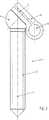
本発明の骨用ネジは、縦方向保持材に角度可変に接続することが望まれる場合の骨の接合に用いることを想定しており、例えば脊椎の外科手術で用いられる。ここでは、骨用ネジが接合ネジ1であるとして記載される。図に描かれた接合ネジ1は、生体埋め込み部材を固定する役割を果たすものであり、これにより脊椎の椎体が矯正され安定になるのである。接合ネジ1は、椎体3中にねじ込むためのネジ脚部2と、ネジ頭部4とからなる。ネジ頭部4は、ネジ穴5を有する円錐台形部6を備えた回転弦形体(球を平面で切断したような形状)として形成される。図示の実施例では、回転弦形体が、ネジ脚部2と一体となった半球7として具現されており、該半球7の直径は、円錐台形部6が当接縁部8によって囲まれるように設定される。円錐台形部6は、そのネジ穴5と共に、ネジ脚部2の縦軸9に対して傾斜して配されている。円錐台形部6及び当接縁部8には、ネジ穴5に噛み合うネジ10により、締付クランプ11が固定される。締付クランプ11は縦方向保持材13のための受入部12を形成する。
【0015】
締付クランプ11は、湾曲クランプ14からなり、互いに平行に延びる脚部15,16が、受入部12を形成するスプリングワッシャー(ばね座金)17によって接続されており、ネジ10を差込むための開口18を有している。開口18の壁は、円錐台形部6の傾斜に対応して傾斜している。また、図5の実施例においては周方向に延びる凹面部19が備えられる。
【0016】
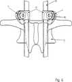
図6及び図7には、脊椎に沿って案内された2つの縦方向保持材13による脊椎の固定及び/または矯正を行うために、すなわち固定及び矯正のいずれかまたは両方を行うために、接合ネジ1がどのように用いられるのかについて示される。この接合ネジ1の形態により、手術の場での作業を簡易なものとすることができる。円錐台形部6が傾斜しているために、ネジ穴5に差し込まれたネジ10へのアクセスが容易であり、比較的大きな回転角にわたっての執刀医による調整が可能だからである。これらネジ10を締付ることで、予め自由に選択可能な締付クランプ11の回転位置と、受入部12中の縦方向保持材13の軸方向の位置とが、摩擦によりロックされ、同時に固定される。
【図面の簡単な説明】
【図1】接合ネジとして実施された本発明の骨用ネジについて、円錐台形部上に配された締付クランプとともに示す軸方向断面である。
【図2】締付クランプを備えた接合ネジの側面図である。
【図3】締付クランプを備えた接合ネジの斜視図である。
【図4】円錐台形部及び当接縁部を備えたネジ頭部の側面図である。
【図5】円錐台形部の周方向に凹面部がぐるりとめぐらされた場合の、図4に対応する側面図である。
【図6】椎骨中にねじ込まれていてそれぞれが1つの縦方向保持材を保持する2つの接合ネジについて示す正面図である。
【図7】図6の矢印VIIの方向からの図である。
【図8】図6の矢印VIIIの方向からの図である。[0001]
The present invention relates to a bone screw for variable angle connection to a longitudinal retainer for osteosynthesis, i.e. for surgical bone stitching. In particular, pedicle screws for implants for spinal correction and fixation, with screw legs for screwing into bones, in particular vertebral bodies of the spine, and longitudinal retainer fixation It is related with a thing provided with a screw head for.
[0002]
Such bone screws are known in practice. The bone screw has teeth that are cut symmetrically with respect to the axis of rotation for fixation at an angle selected from a plurality of possible angular positions.
[0003]
However, since the teeth cut in this way are luxurious, the production cost is high. It is also possible to take only a limited number of discrete angular positions.
[0004]
Joining screws are known, for example, from DE 4107480C2. A known joining screw is composed of two parts, a screw leg part and a screw head part, and is made so as to be connectable to each other by a tenon joint (a tenon-tenon connection). Here, the screw head is composed of a curved portion, and after being placed on the tenon, it is fixed with a set screw. Such joining screws have proven to be good in practice. Certainly, it has been found desirable in certain applications to be able to fix the position after the longitudinal retainer has been fitted with few parts and manipulation after screwing the joining screw into the vertebral body of the spine.
[0005]
Therefore, the problem underlying the present invention is to freely change the position of the longitudinal holding material with respect to the longitudinal axis of the screw in the bone screw as described at the beginning even after the bone screw is arranged. It is possible to configure.
[0006]
<Means for solving the problem>
In the bone screw as described at the beginning, the above problem is solved by the following configuration. The screw head is formed as a rotating chord shape (a solid surrounded by one spherical surface and one plane that cuts it) and a truncated cone portion having a screw hole. The frustoconical portion is arranged so as to be inclined on the longitudinal axis of the screw leg portion by the screw hole. Further, a clamping clamp that provides a receiving portion for the longitudinal holding member can be fixed to the truncated cone portion by a screw that meshes with the screw hole.
[0007]
The advantages obtained by the present invention are as follows. The clamping clamp can be rotated around the frustoconical part together with the loosened screw, and the longitudinal holding material is movable in its longitudinal direction in the receiving part of the clamping clamp. Therefore, the surgeon can easily change the arrangement direction of the longitudinal holding members and the spread of the longitudinal holding member with respect to the bone. If the desired position / posture is achieved because the angular position can be freely selected, the freedom of rotational movement and the freedom of movement are eliminated simultaneously by tightening the screw. Here, it is not necessary to cut teeth for the following reasons. The frustoconical portion has a peripheral surface that is inclined with respect to the rotation axis of the screw that meshes with the screw hole. Therefore, the load moment connecting the clamping clamp and the bone screw does not have to be supported exclusively by friction or engagement by teeth, but is distributed to the surface by the frustoconical part, and the clamping clamp and longitudinal direction This is because it is transmitted as a bending load of the holding material.
[0008]
Here, the purpose is as follows. The frustoconical part is surrounded by an abutting edge provided on the rotating string form. Therefore, a larger abutment surface that is not limited by the side surface of the frustoconical portion can be used.
[0009]
Preferred embodiments of the present invention have the following characteristics. The clamping clamp consists of a curved clamp, the legs extending parallel to each other in this clamping clamp are connected by a spring ring which provides a receiving part and has an opening for inserting a screw. The advantage obtained with this embodiment is that at various stages of tightening the screw, the rotational movement of the clamping clamp or the axial movement of the longitudinal holding material can be limited or eliminated. .
[0010]
It has been found that it is preferable if the wall of the opening for inserting the screw is inclined corresponding to the inclination of the frustoconical part. In this case, not only a line contact is performed and a corresponding large surface pressure is generated, but one larger contact surface is used.
[0011]
If the outer wall of the frustoconical part has a concave surface extending in the circumferential direction, the inclination of the clamping clamp can be changed at least in a restricted state before the screw is tightened.
[0012]
In order to maximize the surface of the abutting edge, it is preferable that the rotating chordal shape is formed as a hemisphere with a shape fused to the screw leg.
[0013]
<Embodiment of the Invention>
In the following, the invention will be described in detail by means of an embodiment depicted in the drawings.
[0014]
The bone screw of the present invention is assumed to be used for bone joining when it is desired to connect the longitudinal holding member with a variable angle, and is used, for example, in spinal surgery. Here, the bone screw is described as being the joining
[0015]
The
[0016]
FIG. 6 and FIG. 7 show joints for performing spinal fixation and / or correction by means of two
[Brief description of the drawings]
FIG. 1 is an axial cross-section showing a bone screw of the present invention implemented as a joining screw, with a clamping clamp disposed on a frustoconical portion.
FIG. 2 is a side view of a joining screw provided with a clamping clamp.
FIG. 3 is a perspective view of a joining screw provided with a clamping clamp.
FIG. 4 is a side view of a screw head having a frustoconical portion and a contact edge portion.
FIG. 5 is a side view corresponding to FIG. 4 when the concave surface portion is swung around in the circumferential direction of the frustoconical portion.
FIG. 6 is a front view showing two joining screws screwed into a vertebra and each holding one longitudinal retainer.
7 is a view from the direction of arrow VII in FIG. 6;
FIG. 8 is a view from the direction of arrow VIII in FIG. 6;
Claims (6)
Translated fromJapanese脊椎の椎体(3)中にねじ込むためのネジ脚部(2)と、
縦方向保持材(13)の固定のために形成されたネジ頭部(4)とを備えた骨用ネジにおいて、
ネジ頭部(4)が、ネジ穴(5)を有する円錐台形部(6)を備えた回転弦形体として形成され、
円錐台形部(6)はそのネジ穴(5)と共にネジ脚部(2)の縦軸(9)に傾斜して配され、
円錐台形部(6)上には、縦方向保持材(13)のための受入部(12)を与える締付クランプ(11)が、ネジ穴(5)に噛み合うネジ(10)により固定可能であることを特徴とする骨用ネジ。A bone screw that is variably connected to a longitudinal holding material for bone joining, in particular, a connection screw for an implant for correcting and fixing the spine,
A screw leg (2) for screwing into the vertebral body (3) of the spine;
In a bone screw with a screw head (4) formed for fixing a longitudinal holding material (13),
The screw head (4) is formed as a rotating string with a frustoconical part (6) having a screw hole (5);
The frustoconical part (6) is inclined with respect to the longitudinal axis (9) of the screw leg part (2) together with the screw hole (5),
On the frustoconical part (6), a clamping clamp (11) for providing a receiving part (12) for the longitudinal holding member (13) can be fixed by a screw (10) meshing with the screw hole (5). A bone screw characterized by being.
Applications Claiming Priority (3)
| Application Number | Priority Date | Filing Date | Title |
|---|---|---|---|
| DE19944120.0 | 1999-09-15 | ||
| DE19944120ADE19944120B4 (en) | 1999-09-15 | 1999-09-15 | Bone screw for variable angle connection with a side member |
| PCT/DE2000/001658WO2001019266A1 (en) | 1999-09-15 | 2000-05-20 | Orthopaedic screw for variable angle connection to a longitudinal support |
Publications (2)
| Publication Number | Publication Date |
|---|---|
| JP2003509106A JP2003509106A (en) | 2003-03-11 |
| JP4119123B2true JP4119123B2 (en) | 2008-07-16 |
Family
ID=7922043
Family Applications (1)
| Application Number | Title | Priority Date | Filing Date |
|---|---|---|---|
| JP2001522906AExpired - Fee RelatedJP4119123B2 (en) | 1999-09-15 | 2000-05-20 | Bone screw for variable angle connection to longitudinal retainer |
Country Status (9)
| Country | Link |
|---|---|
| US (1) | US6423064B1 (en) |
| EP (1) | EP1128771B1 (en) |
| JP (1) | JP4119123B2 (en) |
| AT (1) | ATE337738T1 (en) |
| DE (2) | DE19944120B4 (en) |
| DK (1) | DK1128771T3 (en) |
| ES (1) | ES2265950T3 (en) |
| PT (1) | PT1128771E (en) |
| WO (1) | WO2001019266A1 (en) |
Families Citing this family (67)
| Publication number | Priority date | Publication date | Assignee | Title |
|---|---|---|---|---|
| CA2330705A1 (en)* | 1998-04-29 | 1999-11-04 | Dimso (Distribution Medicale Du Sud-Ouest) | Backbone osteosynthesis system for anterior fixing |
| FR2784282B1 (en) | 1998-10-09 | 2001-03-23 | Dimso Sa | SPINAL OSTEOSYNTHESIS SYSTEM WITH IMPROVED RIGIDITY |
| DE50214457D1 (en) | 2001-10-23 | 2010-07-08 | Biedermann Motech Gmbh | BONE FIXATION DEVICE AND SCREW FOR ONE SUCH |
| EP1608275A4 (en)* | 2003-03-26 | 2009-04-15 | Donald W Bryan | Pedicle screw spinal fixation device |
| US7951176B2 (en) | 2003-05-30 | 2011-05-31 | Synthes Usa, Llc | Bone plate |
| US11259851B2 (en) | 2003-08-26 | 2022-03-01 | DePuy Synthes Products, Inc. | Bone plate |
| DE20321551U1 (en) | 2003-08-26 | 2007-12-27 | Synthes Gmbh | bone plate |
| ES2295708T3 (en)* | 2003-09-08 | 2008-04-16 | Synthes Gmbh | DEVICE FOR OSEA FIXATION. |
| DE20314297U1 (en) | 2003-09-12 | 2003-11-20 | AlloCon GmbH, 42929 Wermelskirchen | bone screw |
| DE50311436D1 (en)* | 2003-10-30 | 2009-05-28 | Synthes Gmbh | BONE PLATE |
| US7637928B2 (en) | 2004-01-26 | 2009-12-29 | Synthes Usa, Llc | Variable angle locked bone fixation system |
| US8574268B2 (en)* | 2004-01-26 | 2013-11-05 | DePuy Synthes Product, LLC | Highly-versatile variable-angle bone plate system |
| US11291484B2 (en) | 2004-01-26 | 2022-04-05 | DePuy Synthes Products, Inc. | Highly-versatile variable-angle bone plate system |
| US20050240181A1 (en)* | 2004-04-23 | 2005-10-27 | Boomer Mark C | Spinal implant connectors |
| US7572282B2 (en)* | 2004-04-23 | 2009-08-11 | Depuy Spine Sarl | Spinal fixation plates and plate extensions |
| US7766945B2 (en)* | 2004-08-10 | 2010-08-03 | Lanx, Inc. | Screw and rod fixation system |
| US7186255B2 (en)* | 2004-08-12 | 2007-03-06 | Atlas Spine, Inc. | Polyaxial screw |
| DE202004020396U1 (en) | 2004-08-12 | 2005-07-07 | Columbus Trading-Partners Pos und Brendel GbR (vertretungsberechtigte Gesellschafter Karin Brendel, 95503 Hummeltal und Bohumila Pos, 95445 Bayreuth) | Child seat for motor vehicles |
| US7736380B2 (en) | 2004-12-21 | 2010-06-15 | Rhausler, Inc. | Cervical plate system |
| US7951175B2 (en)* | 2005-03-04 | 2011-05-31 | Depuy Spine, Inc. | Instruments and methods for manipulating a vertebra |
| US7628799B2 (en) | 2005-08-23 | 2009-12-08 | Aesculap Ag & Co. Kg | Rod to rod connector |
| US20080058808A1 (en) | 2006-06-14 | 2008-03-06 | Spartek Medical, Inc. | Implant system and method to treat degenerative disorders of the spine |
| US7922748B2 (en)* | 2006-06-16 | 2011-04-12 | Zimmer Spine, Inc. | Removable polyaxial housing for a pedicle screw |
| US8048123B2 (en) | 2007-06-05 | 2011-11-01 | Spartek Medical, Inc. | Spine implant with a deflection rod system and connecting linkages and method |
| US8021396B2 (en) | 2007-06-05 | 2011-09-20 | Spartek Medical, Inc. | Configurable dynamic spinal rod and method for dynamic stabilization of the spine |
| US8048115B2 (en) | 2007-06-05 | 2011-11-01 | Spartek Medical, Inc. | Surgical tool and method for implantation of a dynamic bone anchor |
| US8092501B2 (en) | 2007-06-05 | 2012-01-10 | Spartek Medical, Inc. | Dynamic spinal rod and method for dynamic stabilization of the spine |
| US8114134B2 (en) | 2007-06-05 | 2012-02-14 | Spartek Medical, Inc. | Spinal prosthesis having a three bar linkage for motion preservation and dynamic stabilization of the spine |
| US8048128B2 (en) | 2007-06-05 | 2011-11-01 | Spartek Medical, Inc. | Revision system and method for a dynamic stabilization and motion preservation spinal implantation system and method |
| US8052722B2 (en) | 2007-06-05 | 2011-11-08 | Spartek Medical, Inc. | Dual deflection rod system for a dynamic stabilization and motion preservation spinal implantation system and method |
| US8109970B2 (en) | 2007-06-05 | 2012-02-07 | Spartek Medical, Inc. | Deflection rod system with a deflection contouring shield for a spine implant and method |
| US8083772B2 (en) | 2007-06-05 | 2011-12-27 | Spartek Medical, Inc. | Dynamic spinal rod assembly and method for dynamic stabilization of the spine |
| US8048125B2 (en) | 2008-02-26 | 2011-11-01 | Spartek Medical, Inc. | Versatile offset polyaxial connector and method for dynamic stabilization of the spine |
| US8083775B2 (en) | 2008-02-26 | 2011-12-27 | Spartek Medical, Inc. | Load-sharing bone anchor having a natural center of rotation and method for dynamic stabilization of the spine |
| US8267979B2 (en) | 2008-02-26 | 2012-09-18 | Spartek Medical, Inc. | Load-sharing bone anchor having a deflectable post and axial spring and method for dynamic stabilization of the spine |
| US8211155B2 (en) | 2008-02-26 | 2012-07-03 | Spartek Medical, Inc. | Load-sharing bone anchor having a durable compliant member and method for dynamic stabilization of the spine |
| US8007518B2 (en) | 2008-02-26 | 2011-08-30 | Spartek Medical, Inc. | Load-sharing component having a deflectable post and method for dynamic stabilization of the spine |
| US8333792B2 (en) | 2008-02-26 | 2012-12-18 | Spartek Medical, Inc. | Load-sharing bone anchor having a deflectable post and method for dynamic stabilization of the spine |
| US8057517B2 (en) | 2008-02-26 | 2011-11-15 | Spartek Medical, Inc. | Load-sharing component having a deflectable post and centering spring and method for dynamic stabilization of the spine |
| US8097024B2 (en) | 2008-02-26 | 2012-01-17 | Spartek Medical, Inc. | Load-sharing bone anchor having a deflectable post and method for stabilization of the spine |
| US8337536B2 (en) | 2008-02-26 | 2012-12-25 | Spartek Medical, Inc. | Load-sharing bone anchor having a deflectable post with a compliant ring and method for stabilization of the spine |
| US9289220B2 (en)* | 2008-06-24 | 2016-03-22 | Extremity Medical Llc | Intramedullary fixation assembly and method of use |
| US9017329B2 (en) | 2008-06-24 | 2015-04-28 | Extremity Medical, Llc | Intramedullary fixation assembly and method of use |
| US9044282B2 (en) | 2008-06-24 | 2015-06-02 | Extremity Medical Llc | Intraosseous intramedullary fixation assembly and method of use |
| US8303589B2 (en) | 2008-06-24 | 2012-11-06 | Extremity Medical Llc | Fixation system, an intramedullary fixation assembly and method of use |
| US8343199B2 (en) | 2008-06-24 | 2013-01-01 | Extremity Medical, Llc | Intramedullary fixation screw, a fixation system, and method of fixation of the subtalar joint |
| US8328806B2 (en) | 2008-06-24 | 2012-12-11 | Extremity Medical, Llc | Fixation system, an intramedullary fixation assembly and method of use |
| US8313487B2 (en) | 2008-06-24 | 2012-11-20 | Extremity Medical Llc | Fixation system, an intramedullary fixation assembly and method of use |
| US20110230884A1 (en)* | 2008-06-24 | 2011-09-22 | Adam Mantzaris | Hybrid intramedullary fixation assembly and method of use |
| US8603145B2 (en)* | 2008-12-16 | 2013-12-10 | Zimmer Spine, Inc. | Coaxially lockable poly-axial bone fastener assemblies |
| US8998961B1 (en) | 2009-02-26 | 2015-04-07 | Lanx, Inc. | Spinal rod connector and methods |
| US8758346B2 (en) | 2009-09-14 | 2014-06-24 | DePuy Synthes Products, LLC | Variable angle compression plate |
| CN102695465A (en) | 2009-12-02 | 2012-09-26 | 斯帕泰克医疗股份有限公司 | Low profile spinal prosthesis incorporating a bone anchor having a deflectable post and a compound spinal rod |
| US20110307015A1 (en) | 2010-06-10 | 2011-12-15 | Spartek Medical, Inc. | Adaptive spinal rod and methods for stabilization of the spine |
| US8430916B1 (en) | 2012-02-07 | 2013-04-30 | Spartek Medical, Inc. | Spinal rod connectors, methods of use, and spinal prosthesis incorporating spinal rod connectors |
| CN114983546A (en) | 2013-05-13 | 2022-09-02 | 尼奥医疗公司 | Orthopedic implant kit |
| US10905476B2 (en) | 2016-09-08 | 2021-02-02 | DePuy Synthes Products, Inc. | Variable angle bone plate |
| US10820930B2 (en) | 2016-09-08 | 2020-11-03 | DePuy Synthes Products, Inc. | Variable angle bone plate |
| US10624686B2 (en) | 2016-09-08 | 2020-04-21 | DePuy Synthes Products, Inc. | Variable angel bone plate |
| US9814497B1 (en) | 2017-05-09 | 2017-11-14 | King Saud University | Lumbar spine pedicle screw guide |
| US11026727B2 (en) | 2018-03-20 | 2021-06-08 | DePuy Synthes Products, Inc. | Bone plate with form-fitting variable-angle locking hole |
| US10772665B2 (en) | 2018-03-29 | 2020-09-15 | DePuy Synthes Products, Inc. | Locking structures for affixing bone anchors to a bone plate, and related systems and methods |
| US11013541B2 (en) | 2018-04-30 | 2021-05-25 | DePuy Synthes Products, Inc. | Threaded locking structures for affixing bone anchors to a bone plate, and related systems and methods |
| US10925651B2 (en) | 2018-12-21 | 2021-02-23 | DePuy Synthes Products, Inc. | Implant having locking holes with collection cavity for shavings |
| CN113795211B (en) | 2019-03-26 | 2024-11-29 | 尼奥医疗公司 | System for tightening an orthopedic set screw at two different torque levels |
| ES2988747T3 (en) | 2019-07-02 | 2024-11-21 | Neo Medical Sa | System to prevent lateral tension on bone structures resulting from off-axis forces caused by the screwdriver and screw extender |
| CN115568924B (en)* | 2020-11-12 | 2024-09-27 | 上海三友医疗器械股份有限公司 | Internal fixation structure of spine and internal fixation system thereof |
Family Cites Families (10)
| Publication number | Priority date | Publication date | Assignee | Title |
|---|---|---|---|---|
| DE4107480C2 (en)* | 1991-03-08 | 1994-09-22 | Heinrich Ulrich | Pedicle screw for implants to correct and stabilize the spine |
| JP3308271B2 (en) | 1992-06-25 | 2002-07-29 | ジンテーズ アクチエンゲゼルシャフト,クール | Osteosynthesis fixation device |
| FR2709412B1 (en)* | 1993-09-01 | 1995-11-24 | Tornier Sa | Screw for lumbo-sacral fixator. |
| FR2724553B1 (en)* | 1994-09-15 | 1996-12-20 | Tornier Sa | EXTERNAL OR INTERNAL FIXER FOR THE REPAIR OF FRACTURES OR ARTHROPLASTIES OF THE SKELETON |
| FR2731344B1 (en)* | 1995-03-06 | 1997-08-22 | Dimso Sa | SPINAL INSTRUMENTATION ESPECIALLY FOR A ROD |
| US5569247A (en)* | 1995-03-27 | 1996-10-29 | Smith & Nephew Richards, Inc. | Enhanced variable angle bone bolt |
| US5613968A (en)* | 1995-05-01 | 1997-03-25 | Lin; Chih-I | Universal pad fixation device for orthopedic surgery |
| US5725528A (en)* | 1997-02-12 | 1998-03-10 | Third Millennium Engineering, Llc | Modular polyaxial locking pedicle screw |
| IES77331B2 (en)* | 1997-06-03 | 1997-12-03 | Tecos Holdings Inc | Pluridirectional and modulable vertebral osteosynthesis device of small overall size |
| DE29712697U1 (en) | 1997-07-18 | 1997-09-25 | ENDOTEC Vertriebs- und Beratungsgesellschaft für Medizintechnik mbH, 51399 Burscheid | Spinal fixator |
- 1999
- 1999-09-15DEDE19944120Apatent/DE19944120B4/ennot_activeExpired - Fee Related
- 2000
- 2000-05-20PTPT00943628Tpatent/PT1128771E/enunknown
- 2000-05-20ATAT00943628Tpatent/ATE337738T1/ennot_activeIP Right Cessation
- 2000-05-20EPEP00943628Apatent/EP1128771B1/ennot_activeExpired - Lifetime
- 2000-05-20USUS09/831,972patent/US6423064B1/ennot_activeExpired - Lifetime
- 2000-05-20ESES00943628Tpatent/ES2265950T3/ennot_activeExpired - Lifetime
- 2000-05-20WOPCT/DE2000/001658patent/WO2001019266A1/enactiveIP Right Grant
- 2000-05-20DEDE50013396Tpatent/DE50013396D1/ennot_activeExpired - Lifetime
- 2000-05-20DKDK00943628Tpatent/DK1128771T3/enactive
- 2000-05-20JPJP2001522906Apatent/JP4119123B2/ennot_activeExpired - Fee Related
Also Published As
| Publication number | Publication date |
|---|---|
| US6423064B1 (en) | 2002-07-23 |
| EP1128771B1 (en) | 2006-08-30 |
| ATE337738T1 (en) | 2006-09-15 |
| PT1128771E (en) | 2006-11-30 |
| DE19944120B4 (en) | 2008-08-28 |
| DE19944120A1 (en) | 2001-03-22 |
| DK1128771T3 (en) | 2006-12-27 |
| DE50013396D1 (en) | 2006-10-12 |
| JP2003509106A (en) | 2003-03-11 |
| WO2001019266A1 (en) | 2001-03-22 |
| ES2265950T3 (en) | 2007-03-01 |
| EP1128771A1 (en) | 2001-09-05 |
Similar Documents
| Publication | Publication Date | Title |
|---|---|---|
| JP4119123B2 (en) | Bone screw for variable angle connection to longitudinal retainer | |
| JP5654584B2 (en) | Correction connector for spine construction | |
| JP5006926B2 (en) | Method and apparatus for interconnecting bone appliers | |
| JP5193025B2 (en) | Facial joint implant cross-linking system | |
| RU2302839C2 (en) | Implant having multiaxial head fixable in bone | |
| US9421042B2 (en) | Bone fixation apparatus | |
| EP1954206B1 (en) | Dorsal adjusting multi-rod connector | |
| JP4131612B2 (en) | Vertebral joint device | |
| US9554837B2 (en) | Device for fixing an elongate element in a retaining structure | |
| US8167912B2 (en) | Modular pedicle screw system | |
| US7951173B2 (en) | Pedicle screw implant system | |
| EP0981300B1 (en) | Articulating toggle bolt bone screw | |
| JP5187594B2 (en) | Transformer connector | |
| US7144396B2 (en) | Apparatus for connecting a longitudinal member to a bone portion | |
| JP5713972B2 (en) | Spinous process fixation graft | |
| JP4128224B2 (en) | Modular multi-axis locking stem screw | |
| US7722648B2 (en) | Crosslink interconnection of bone attachment devices | |
| US8361120B2 (en) | Outrigger | |
| JP2003504105A (en) | Angle adjustable bone screw and osteosynthetic bone fixation device | |
| JP2003526444A (en) | Polyaxial bone anchor system | |
| JP2009512466A (en) | Multi-axis screw | |
| KR101166614B1 (en) | Orthopedic plate system | |
| US20250312070A1 (en) | Double tulip spinal fixation connectors and related methods and apparatus | |
| RU2283630C2 (en) | Device for osteosynthesis |
Legal Events
| Date | Code | Title | Description |
|---|---|---|---|
| A621 | Written request for application examination | Free format text:JAPANESE INTERMEDIATE CODE: A621 Effective date:20061114 | |
| A977 | Report on retrieval | Free format text:JAPANESE INTERMEDIATE CODE: A971007 Effective date:20080311 | |
| TRDD | Decision of grant or rejection written | ||
| A01 | Written decision to grant a patent or to grant a registration (utility model) | Free format text:JAPANESE INTERMEDIATE CODE: A01 Effective date:20080325 | |
| A61 | First payment of annual fees (during grant procedure) | Free format text:JAPANESE INTERMEDIATE CODE: A61 Effective date:20080424 | |
| R150 | Certificate of patent or registration of utility model | Free format text:JAPANESE INTERMEDIATE CODE: R150 | |
| FPAY | Renewal fee payment (event date is renewal date of database) | Free format text:PAYMENT UNTIL: 20110502 Year of fee payment:3 | |
| LAPS | Cancellation because of no payment of annual fees |