JP4116143B2 - Ultrasonic diagnostic equipment - Google Patents
Ultrasonic diagnostic equipmentDownload PDFInfo
- Publication number
- JP4116143B2 JP4116143B2JP09939698AJP9939698AJP4116143B2JP 4116143 B2JP4116143 B2JP 4116143B2JP 09939698 AJP09939698 AJP 09939698AJP 9939698 AJP9939698 AJP 9939698AJP 4116143 B2JP4116143 B2JP 4116143B2
- Authority
- JP
- Japan
- Prior art keywords
- fundamental
- fundamental wave
- ultrasonic
- wave mode
- mode
- Prior art date
- Legal status (The legal status is an assumption and is not a legal conclusion. Google has not performed a legal analysis and makes no representation as to the accuracy of the status listed.)
- Expired - Fee Related
Links
Images
Classifications
- G—PHYSICS
- G01—MEASURING; TESTING
- G01S—RADIO DIRECTION-FINDING; RADIO NAVIGATION; DETERMINING DISTANCE OR VELOCITY BY USE OF RADIO WAVES; LOCATING OR PRESENCE-DETECTING BY USE OF THE REFLECTION OR RERADIATION OF RADIO WAVES; ANALOGOUS ARRANGEMENTS USING OTHER WAVES
- G01S15/00—Systems using the reflection or reradiation of acoustic waves, e.g. sonar systems
- G01S15/88—Sonar systems specially adapted for specific applications
- G01S15/89—Sonar systems specially adapted for specific applications for mapping or imaging
- G01S15/8906—Short-range imaging systems; Acoustic microscope systems using pulse-echo techniques
- G01S15/8979—Combined Doppler and pulse-echo imaging systems
- G01S15/8988—Colour Doppler imaging
- G—PHYSICS
- G01—MEASURING; TESTING
- G01S—RADIO DIRECTION-FINDING; RADIO NAVIGATION; DETERMINING DISTANCE OR VELOCITY BY USE OF RADIO WAVES; LOCATING OR PRESENCE-DETECTING BY USE OF THE REFLECTION OR RERADIATION OF RADIO WAVES; ANALOGOUS ARRANGEMENTS USING OTHER WAVES
- G01S7/00—Details of systems according to groups G01S13/00, G01S15/00, G01S17/00
- G01S7/52—Details of systems according to groups G01S13/00, G01S15/00, G01S17/00 of systems according to group G01S15/00
- G01S7/52017—Details of systems according to groups G01S13/00, G01S15/00, G01S17/00 of systems according to group G01S15/00 particularly adapted to short-range imaging
- G01S7/52023—Details of receivers
- G01S7/52036—Details of receivers using analysis of echo signal for target characterisation
- G01S7/52038—Details of receivers using analysis of echo signal for target characterisation involving non-linear properties of the propagation medium or of the reflective target
- G—PHYSICS
- G01—MEASURING; TESTING
- G01S—RADIO DIRECTION-FINDING; RADIO NAVIGATION; DETERMINING DISTANCE OR VELOCITY BY USE OF RADIO WAVES; LOCATING OR PRESENCE-DETECTING BY USE OF THE REFLECTION OR RERADIATION OF RADIO WAVES; ANALOGOUS ARRANGEMENTS USING OTHER WAVES
- G01S7/00—Details of systems according to groups G01S13/00, G01S15/00, G01S17/00
- G01S7/52—Details of systems according to groups G01S13/00, G01S15/00, G01S17/00 of systems according to group G01S15/00
- G01S7/52017—Details of systems according to groups G01S13/00, G01S15/00, G01S17/00 of systems according to group G01S15/00 particularly adapted to short-range imaging
- G01S7/52046—Techniques for image enhancement involving transmitter or receiver
- G—PHYSICS
- G01—MEASURING; TESTING
- G01S—RADIO DIRECTION-FINDING; RADIO NAVIGATION; DETERMINING DISTANCE OR VELOCITY BY USE OF RADIO WAVES; LOCATING OR PRESENCE-DETECTING BY USE OF THE REFLECTION OR RERADIATION OF RADIO WAVES; ANALOGOUS ARRANGEMENTS USING OTHER WAVES
- G01S7/00—Details of systems according to groups G01S13/00, G01S15/00, G01S17/00
- G01S7/52—Details of systems according to groups G01S13/00, G01S15/00, G01S17/00 of systems according to group G01S15/00
- G01S7/52017—Details of systems according to groups G01S13/00, G01S15/00, G01S17/00 of systems according to group G01S15/00 particularly adapted to short-range imaging
- G01S7/52023—Details of receivers
- G01S7/52034—Data rate converters
- G—PHYSICS
- G01—MEASURING; TESTING
- G01S—RADIO DIRECTION-FINDING; RADIO NAVIGATION; DETERMINING DISTANCE OR VELOCITY BY USE OF RADIO WAVES; LOCATING OR PRESENCE-DETECTING BY USE OF THE REFLECTION OR RERADIATION OF RADIO WAVES; ANALOGOUS ARRANGEMENTS USING OTHER WAVES
- G01S7/00—Details of systems according to groups G01S13/00, G01S15/00, G01S17/00
- G01S7/52—Details of systems according to groups G01S13/00, G01S15/00, G01S17/00 of systems according to group G01S15/00
- G01S7/52017—Details of systems according to groups G01S13/00, G01S15/00, G01S17/00 of systems according to group G01S15/00 particularly adapted to short-range imaging
- G01S7/52053—Display arrangements
- G01S7/52057—Cathode ray tube displays
- G01S7/5206—Two-dimensional coordinated display of distance and direction; B-scan display
Landscapes
- Engineering & Computer Science (AREA)
- Physics & Mathematics (AREA)
- Radar, Positioning & Navigation (AREA)
- Remote Sensing (AREA)
- Computer Networks & Wireless Communication (AREA)
- General Physics & Mathematics (AREA)
- Acoustics & Sound (AREA)
- Nonlinear Science (AREA)
- Ultra Sonic Daignosis Equipment (AREA)
- Investigating Or Analyzing Materials By The Use Of Ultrasonic Waves (AREA)
- Apparatuses For Generation Of Mechanical Vibrations (AREA)
- Length Measuring Devices Characterised By Use Of Acoustic Means (AREA)
Description
Translated fromJapanese【0001】
【発明の属する技術分野】
本発明は、超音波の非線形な伝搬により生じる高調波成分を取りだし、この高調波成分に基づいて超音波画像を生成し、表示する超音波診断装置に関する。
【0002】
【従来の技術】
上記ハーモニックイメージング(HI)法と呼ばれている手法は、超音波の受信信号に含まれる高調波成分を検出して、映像化する手法であり(例えば2MHzの超音波を送信し、4MHzの高調波でイメージング)、微小気泡よりなる超音波造影剤をより効率的に検出することを目的として開発された。
【0003】
微小気泡は強い非線形散乱特性を有しており、その散乱信号は生体組織と比べて大きな高調波成分を含んでいる。そこでこの高調波成分のみを検出することにより、通常(基本波)では周囲組織からのエコーに埋もれてしまような微小な血流(パフュージョン)の映像化が可能となる。
【0004】
近年、ハーモニックイメージング法の他の応用として、組織ハーモニック映像法(Tissue Harmonic Imaging;THI)が注目されている。これはハーモニックイメージング法が有する画質改善効果に着目したもので、いわゆるタフペイシャントにおいてもノイズの低減された高コントラストのBモード画像が得られ、心内膜等の描出に優れることが特徴である。
【0005】
ハーモニックイメージング法ではコントラスト剤(微小気泡)での非線形な“散乱”信号を映像化するのに対して、組織ハーモニック映像法では、送信された超音波が生体内を歪みながら“伝搬”するいわゆる伝搬の非線形性により発生する高調波を映像化している。
【0006】
この高調波の振幅は、超音波の伝搬距離および基本波の音圧の二乗に比例するため、超音波ビームの中心軸上(音圧の高い領域)に集中して発生する。すなわち基本波を用いた場合に比べ、メインローブが細くかつサイドローブレベルが低いシャープな超音波ビームが形成可能である。
【0007】
このようにハーモニック映像法ではビーム幅が狭くかつサイドローブレベルの低いビーム形成が可能なため、ビーム幅の低減により方位方向分解能が向上し、またサイドローブレベルの低減によりコントラスト分解能が向上する。
【0008】
このような数々の優位性が予測されているにも関わらず、実際に組織ハーモニックイメージングを行うと、(1)高調波があまり効率的に発生せず思ったほど画質が向上しない、(2)超音波を収束させているはずの関心領域において画質があまり向上しない、(3)通常のイメージングと組織ハーモニックイメージングとを切り替えると、その都度、画質の高い領域の場所が変わってしまう、(4)関心領域が体表から浅い領域にあるような場合には、十分な伝搬距離を確保できず、高調波成分があまり発生せず、映像化が困難となる、
といったいろいろな問題が生じている。
【0009】
【発明が解決しようとする課題】
本発明の目的は、高調波画像の画質を向上し得る超音波診断装置を提供することにある。
【0010】
【課題を解決するための手段】
本発明は、基本周波数の超音波を被検体に送信し、この被検体から返ってくる反射波に含まれる前記基本周波数の成分を主体として前記被検体内を映像化する基本波モードと、前記反射波に含まれる前記基本周波数以外の非基本周波数の成分を主体として前記被検体内を映像化する非基本波モードとで選択可能に動作することが可能に構成された超音波診断装置において、前記超音波の収束強度を、前記基本波モードのときよりも前記非基本波モードのときに高く設定することを特徴とする。
【0019】
【発明の実施の形態】
以下、本発明を好ましい実施形態により図面を参照しながら説明する。
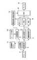
図1に、本実施形態による超音波診断装置の構成を示している。超音波プローブ2の先端部分には、電気信号と音響信号とを相互変換するための複数の圧電素子が配列されている。なお、ここでは、1圧電素子が1チャンネルを構成するものとして説明する。このプローブ2には、送信回路1が接続されている。この送信回路1は、超音波をビーム状に形成し、また任意の深さで収束させて焦点を形成するように遅延処理をかけた駆動信号(高周波電圧)を、プローブ2の各チャンネルに印加する。これにより、各チャンネルの圧電素子は振動し、超音波を発生する。なお、この超音波の周波数スペクトラムは、駆動信号の周波数(基本周波数f0 )を中心として通常は若干分散している。
【0020】
プローブ2から発生された超音波は、被検体に送信され、被検体内部を伝播し、その途中にある音響インピーダンスの不連続面で反射し、エコーとしてプローブ2に返ってくる。このエコーには、基本周波数f0 の基本波成分の他に、超音波が生体内を歪みながら“伝搬”するいわゆる伝搬の非線形性により基本周波数f0 以外の非基本波成分が発生する。この非基本波成分としては、ここでは、基本周波数f0 の整数倍の高調波成分、特に基本周波数f0 の2倍の二次高調波成分を扱うものとするが、それ以外に、超音波を少なくとも2種類の基本周波数で送信され、非基本波成分は、この2種類の基本周波数どうしの和あるいは差の周波数成分でもよいし、2種類の基本周波数それぞれの高調周波数の和あるいは差の周波数成分でもよいし、2種類の基本周波数とそれぞれの高調周波数との和あるいは差の周波数成分でもよい。
【0021】
プローブ2に返ってきたエコーは、送信時とは逆に、圧電素子を機械的に振動させ、微弱な電気信号を発生させる。この信号は、受信回路3に取り込まれ、プリアンプで増幅され、送信時と同じ遅延処理を経て加算される。この受信信号は、基本波モード(通常のイメージング法)時には、受信信号から基本波成分を主に抽出するために通過帯域が基本周波数f0 を中心とした所定の帯域に設定されている基本波用帯域通過型フィルタ(BPF)4を通って、また高調波モード(組織ハーモニック映像法)時には、受信信号から高調波成分を抽出するために通過帯域が基本周波数f0 の2倍の周波数を中心とした所定の帯域に設定されている高調波用帯域通過型フィルタ(BPF)5を通って、Bモード処理系6、カラーフローマッピング(CFM)処理系7、パルス波(PW)処理系8に送られる。
【0022】
Bモード処理系6は、基本波モード時には基本波用帯域通過型フィルタ4からの基本波成分に基づいて通常のBモード像を生成し、また高調波モード時には高調波用帯域通過型フィルタ5からの高調波成分に基づいて組織ハーモニック画像を生成する。また、カラーフローマッピング処理系7とパルス波(PW)処理系8はそれぞれ、基本波用帯域通過型フィルタ4からの基本波成分又は高調波用帯域通過型フィルタ5からの高調波成分に基づいて血流画像、周波数スペクトラムを生成する。これら画像はディジタルスキャンコンバータ(DSC)9を介してモニタに表示される。
【0023】
送信制御回路12は、操作者によってモード入力部13から入力された関心領域(ROI)の位置(深さ)及びモード(基本波モード又は高調波モード)に対応する送信条件を送信条件メモリ11から入手し、この入手した送信条件に従って送信回路1を制御して送信周波数、送信時の焦点深度、送信開口の口径等の動作状態を調整するようになっている。また、高調波発生領域演算部14は、上記送信条件に従って高調波成分が最も強く発生する領域の場所(向きと深さ)を演算し、又は様々な送信条件に従って高調波成分が最も強く発生する領域(高調波成分の最大音圧領域)の場所を事前に演算しておき、この演算結果を保管しておいたメモリから送信条件に合致する当該場所を読み出し、そして、この高調波成分が最も強く表れる領域を示すマーカをディジタルスキャンコンバータ9に出力する。このマーカは、音圧分布、Bモード像、組織ハーモニック画像に合成され、高調波焦点の場所を観察者に提示するようになっている。
【0024】
ここで、基本波モードと高調波モードとは、操作者が入力部13を適当なモード切り替え操作したときに切り替わるようにしてもよいし、1断面分を1回走査する毎に、又は1回送受信する毎に自動的に切り替えるようにしてもよい。さらには、切り替えせずに、同じ受信信号を2つのフィルタ4,5に分配し、それぞれを通過した信号から個別に画像を生成するようにしてもよい。ただし、モード切り替えによって両画像がそれそれ別個の送受信で形成されることが両画像がそれぞれを最適な画質で得る上で望ましく、つまり、それぞれの最適な画質を得るために、後述するように、送信開口の口径、超音波の焦点深度、送信周波数等の送信条件を独立に設定することが望ましい。
【0025】
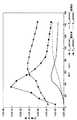
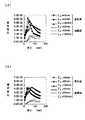
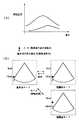
この高調波モードで最適な画質を得るための送信条件に付いて説明する。まず、発明者らは、実際に基本波成分と高調波成分の中心軸上の音圧分布を、焦点深度を40mmと80mmとの2種類で求めた。その結果を、図2に示している。なお、焦点Z0 は、超音波合成による計算上の超音波焦点として定義され、基本波の場合にはその最大音圧点は、焦点Z0 とほぼ合致する。高調波成分が最大音圧を示す領域は、焦点Z0 よりも若干深い場所に現れるという事態に注目した。このような事態が生じるのは、高調波の発生が超音波の伝搬距離および基本波の音圧の二乗に比例するためである。
【0026】
そこで本発明では、基本波モードでは超音波の焦点を関心領域に合わせるが、高調波モードでは超音波の焦点を関心領域よりも若干浅い場所に合わせるように送信条件を設定しておくことにより、基本波モードでも高調波モードでも最大音圧を示す領域を、関心領域に合わすことができ、これによりいずれのモードでも関心領域の画質を向上させ、通常の基本波モードと高調波モードとを切り替えるときに画質の高い領域の場所が変わってしまうようなことを防止することができる。
【0027】
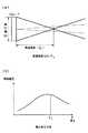
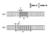
次に、高調波を特に浅い部分で効率的に発生させる手法について説明する。まず、ここで収束強度について定義しておく。この収束強度fは、超音波をどの程度収束させるかを表しており、超音波の音圧分布を定義する上で重要なパラメータであり、図3(a)、(b)に示すように、送信開口の口径をD、焦点深度をZ0 として、“D/Z0 ”で与えられる。周知の通り、口径Dは、駆動チャンネル数を変えることにより、また焦点深度Z0 は遅延時間を変えることにより、それぞれ調整することができる。なお、焦点深度Z0 は操作者により設定される関心領域に従って決まるので、当該収束強度fは専ら口径Dの変更により調整される。
【0028】
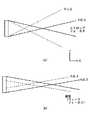
また、ストロングフォーカスについて説明する。ストロングフォーカスとは、基本波成分を主にイメージングするBモードの映像法で一般的なウィークフォーカスで使われている収束強度f=0.3よりも高い、例えば0.5以上の収束強度で超音波を収束させるように送信することをいい、図4(a)には収束強度fが1.0と0.5のときのストロングフォーカスでの超音波の音場を模式的に示している。同様に、図4(b)には収束強度fが0.3のときのウィークフォーカスでの超音波の音場を模式的に示している。
【0029】
収束強度fが0.3以下という比較的小さい場合には、比較的広い範囲に渡って均一な音圧分布が得られる。逆に比較的大きい場合には、超音波は局所的に収束する。
【0030】
図4(a)、(b)から明らかなように、通常の基本波成分による映像法で、広範囲に渡って均一な画質を得ようとすると、収束強度をあまり大きくすることはできず、上述したように収束強度としては0.3を上限値としている調整している。そこで通常は、図4(b)にように、収束強度が変化しないように、焦点深度が浅くなると、それに応じて口径を狭くしている。
【0031】
図5(a),(b)に、図4(a),(b)の音場における中心軸上の音圧分布を示している。図5(b)は通常の基本波成分による映像法で一般的に用いられる音場であり、焦点を変更させても基本波成分の音圧ピークが略均一に保たれている。これはすでに述べた通り、収束強度をほぼ一定に保った結果である。
【0032】
この基本波音場による高調波の発生をシミュレーションにより計算すると、基本波音場の均一性とは対照的に不均一となり、しかも近距離の領域でほとんど発生していない。
【0033】
一方、図4(a)や図5(a)のようにストロングフォーカスを行うことにより、高調波成分を均一に、しかも近距離領域から効率的に発生させることができる。
【0034】
以上をまとめると、超音波の焦点に関しては、基本波モードでは関心領域に合わせ、一方、高調波モードでは関心領域よりも浅い場所に合わせる。また、収束強度に関しては、基本波モードでは例えば0.3以下という比較的低い値を採用してウィークフォーカスで送信し、一方、高調波モードでは例えば0.5以上という比較的高い値を採用して、ストロングフォーカスで送信する。
【0035】
このような規則に従って送信条件を基本波モードと高調波モードとで使い分けることにより、基本波モードでも高調波モードでも最大音圧を示す領域を、関心領域に合わすことができ、これによりいずれのモードでも関心領域の画質を向上させることができ、また、基本波成分による通常の映像法と組織ハーモニック映像法とを切り替えるときに画質の高い領域の場所が変わってしまうようなことを防止することができ、しかも浅い部分でも高調波を効率的に発生させることができる。
【0036】
なお、送信条件メモリには、非基本波成分による映像化のための送信条件と、基本波成分による映像化の送信条件とを別テーブルとして独立に持つことが望ましい。メモリ容量あるいは、参照テーブル切り替えの制約から別テーブルを持てない場合には、各フォーカス点毎のデータとして、近距離のフォーカス段分には前記非基本波成分用のデータを、遠距離のデータには基本波成分用のデータを持つ方法もある。
【0037】
ここで上述したように、超音波の焦点に関しては、基本波モードでは関心領域に合わせ、一方、高調波モードでは関心領域よりも浅い場所に合わせるとしたが、これについてもう少し具体的に説明する。ここでは、通常の基本波による映像法、つまり基本波モードから、組織ハーモニック映像法、つまり高調波モードに切り替える場合を想定する。
【0038】
上述したように、高調波成分は基本波成分の音圧分布に追従するように若干深い場所で強く発生するので、超音波の焦点を変えずに切り替えると、関心領域では高調波は十分に発生しないことになる。そこで、このようにモードを切り替える際に、これと連動して、焦点を若干浅くするように送信条件を切り替える。例えば基本波による通常の映像法における焦点深度が、
30mm、40mm、50mm、80mm、120mm
のとき、高調波成分が最も強く表れる場所は、
35mm、50mm、60mm、100mm、140mm
それぞれの深さになる。従って、例えば関心領域が50mmの深さにあるときには、基本波モードではそのまま50mmに超音波の焦点を合わせ、一方、高調波モードでは、40mmの深さに超音波の焦点を合わせることにより、高調波成分が最大音圧となる場所が関心領域に丁度合うようになる。
【0039】
このような最大音圧点の対応関係をメモり11に保管させておき、基本波モードから高調波モードに又はその逆に切り替えたとき、音圧が最大となる深さが変化しないように、焦点深度を自動的に変えるようにすることで、両映像法を切り替えても画像内でもっとも良好な画質が得られる領域の場所が変化しないで、手動で焦点深度を変える必要がなくなる。
【0040】
上述したように、高調波モードでは例えば0.5以上という比較的高い値を採用して、ストロングフォーカスで送信するものであるが、これは、焦点深度Z0 が操作者により設定された関心領域により決めるので、収束強度fは送信開口の口径Dにより調整することになる。
【0041】
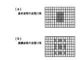
図6(a)に通常の基本波モードでの映像法のときの駆動チャンネルと口径を示し、図6(b)に高調波モードでの組織ハーモニック映像法のときの駆動チャンネルと口径を示している。ここでは、1次元アレイ型のプローブ2において、1本のラスターを生成するために同時駆動するチャンネル数が8の例である。通常のBモードでは、主にグレーティングローブを考慮して、チャンネルピッチが設計されているため、連続した8つのチャンネルが駆動され、送信の超音波ビームが形成される。なお、グレーティングローブを考慮するというのは、周知の通り、メインローブからグレーティングローブまでの距離はチャンネルピッチをPとして、1/Pで与えられる。つまり、チャンネルピッチが短ければ短いほど、メインローブからグレーティングローブを離すことができるのである。
【0042】
しかし、高調波では、その発生原理から考えると、チャンネルピッチをより広い間隔にとっても、この間隔の拡大に対してグレーティングローブはあまり上昇しないため、同時駆動チャンネルが仮に8チャンネルしかなくても、例えば図6(b)に示すように1チャンネルずつ間引いて同時駆動することにより、実質的に口径を拡大して、必要な収束強度を獲得することができる。もちろん、この間引きは、1チャンネルずつでなくても、2チャンネル又はそれ以上ずつ間引いてもよいし、口径の外側ほど間引きの間隔を広げるようにしてもよい。また、間引かれた素子を、隣接する素子と同一のパルサーに短絡し、例えば、2素子で1チャンネルを構成することも考えられる。
【0043】
このような考えは、図7に示すように、チャンネルが2次元状に配列されているいわゆる2次元アレイ型のプローブの場合にも適用できる。つまり、基本波モードでは、図7(a)に示すように、隣接する例えば16チャンネルを同時駆動し、一方、高調波モードでは、図7(b)に示すように、離散的に16チャンネルを同時駆動して、縦横に口径を拡大する。
【0044】
なお、2次元アレイでは、送信チャンネル数をシステムの同時駆動可能なチャンネル数以内にするために、間引き駆動が提案されている。しかしながら、この間引きの設計基準は、基本波での送受信を前提としたサイドローブやグレーティングローブレベルの発生を抑えるという方向付けで行われる。これに対して、本発明では、このような方向付けは不要であり、つまり収束強度に基づいて駆動チャンネルを分散させることができる。
【0045】
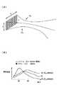
上述したように超音波プローブ2としては図8(a)に示すような2次元アレイ型を採用してもよく、この2次元アレイ型プローブで、縦方向と横方向とにそれぞれ同じ深度にストロングフォーカスをかけることにより、図8(b)に示すように1次元アレイ型の場合よりも、より効率的に高調波を発生させることができる。つまり、1次元アレイでは、レンズ方向の焦点が固定であるため、可変なのはスキャン方向(横方向)のフォーカスのみである。レンズフォーカスが例えば60mmで固定されている場合には、近距離にストロングフォーカスしても図8(a)に示すように、急峻な収束音場は得られずに、両者の中間にピークがくるような緩やか軸上分布となる。
【0046】
一方、2次元アレイ型ではエレべーション方向(縦方向)、スキャン方向(横方向)ともに焦点深度を制御することが可能であり、効率的に高調波を発生させ、高画質の組織ハーモニック画像が得ることができる。
【0047】
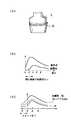
ところで、ストロングフォーカスをかけても、それ以上に浅い場所に関心領域があるような場合が考えられる。このような事態に対処するために、ここではプローブ2に着脱自在な音響カプラを提供している。
【0048】
図9(a)にこの音響カプラの外観を示す。この音響カプラ21は、ケーシング内に、少なくともマイクロバブルを混入させた水、又はゼラチン状の超音波が非線形に伝搬して多くの高調波を発生するような非線形媒質を封入してなる。図9(b)に示すようにカプラ21を装着しなければ、体表から1乃至2cm程度の非常に浅い領域では高調波は発生しないが、このようなカプラ21をプローブ2の送受信面に装着することで、プローブ2の先端から生体までの距離を実質的に延長し、且つその間に発生する高調波成分によって図9(c)に示すように近距離領域でも高調波を効果的に発生させることができ、従って浅い領域でも高画質で組織ハーモニック画像を生成することができる。
【0049】
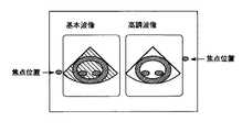
次に、画像表示に関して説明する。この表示の特徴としては、高調波成分の最大音圧点は送信条件から発生領域演算部14で求めることができるので、この高調波成分の最大音圧点を観察者に提示しようとする点にある。図10(a)に示すように、基本波の音圧分布と高調波の音圧分布に対して、それぞれの最大音圧点の深度をマーカで表すようにしてもよいし、また、図10(b)に示すように、基本波モードでの基本波成分による画像や高調波モードでの高調波成分による画像の対して同様のマーカを添付するようにしてもよい。このように最大音圧点を提示することで、操作者は高調波モードにおいても、例えば手動で高調波成分の最大音圧点を関心領域に合わせてその領域の高画質なハーモニック画像を得ることができる。
【0050】
また、図11に示すように、基本波成分を主体としたBモード画像(基本波画像)と、高調波モードの高調波成分を主体としたBモード画像(高調波画像)とを、同一画面内に並列に並べて同時表示するようにしてもよい。このときには、超音波の焦点の深さを表すマーカを付けると、関心領域にそれぞれの成分の最大音圧点が合っているか否かを把握でき、好ましい。
【0051】
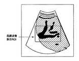
さらに、基本波画像と高調波画像とを同時表示する際、図12に示すように、基本波画像と高調波画像とを部分的に合成して、具体的には、関心領域を高調波画像で構成し、関心領域以外の領域を基本波画像で構成して、表示するようにしてもよい。このような部分的な合成表示は、高調波画像は原理的に近距離部と遠距離部に画質が悪くなるという欠点があり、その欠点を基本波画像で補って、近距離から遠距離まで高画質で提供することができる。
本発明は、上述の実施形態に限定されること無く、種々変形して実施可能である。
【0052】
【発明の効果】
本発明によると、高調波画像の画質を向上させることができる。
【図面の簡単な説明】
【図1】本発明の好ましい実施形態による超音波診断装置のブロック図。
【図2】基本波成分と高調波成分の音圧分布を示す図。
【図3】(a)は収束強度の説明図、(b)は中心軸状の音圧分布を示す図。
【図4】(a)はストロングフォーカスを使ったときの高調波成分の音場を示し、(b)はウィークフォーカスのときの基本波成分の音場を示す図。
【図5】(a)は収束強度fが1.0のストロングフォーカスを様々な深さにかけたときの基本波成分と高調波成分それぞれの音圧分布を示し、(b)は収束強度fが0.5の通常のウィークフォーカスを様々な深さにかけたときの基本波成分と高調波成分それぞれの音圧分布を示す図。
【図6】(a)は基本波モード(ウィークフォーカス)時の口径及び駆動チャンネルを示す図、(b)は高調波モード(ストロングフォーカス)時の口径及び駆動チャンネルを示す図。
【図7】(a)はプローブが2次元アレイ型のときの基本波モード(ウィークフォーカス)時の口径及び駆動チャンネルを示す図、(b)はプローブが2次元アレイ型のときの高調波モード(ストロングフォーカス)時の口径及び駆動チャンネルを示す図。
【図8】(a)は超音波プローブを2次元アレイ型のときに縦横にストロングフォーカスをかけたとき音場を示す図、(b)はこのときの中心軸状の音圧分布を1次元アレイの場合と比較して示す図。
【図9】(a)は超音波プローブに装着したときの音響カプラの外観図、(b)は音響カプラを装着しないときの音圧分布を示す図、(c)は音響カプラを装着したときの音圧分布を示す図。
【図10】(a)は高調波の最大音圧点を音圧分布に対して添付する表示例を示す図、(b)は高調波の最大音圧点を画像に対して添付する表示例を示す図。
【図11】基本波画像と高調波画像とを略同時に同一画面に並べて表示する場合の表示画面例を示す図。
【図12】関心領域(ROI)内を高調波画像で、関心領域以外を基本波画像でそれぞれ構成するように両画像を部分的に合成して表示する場合の表示画面例を示す図。
【符号の説明】
1…送信回路、
2…超音波プローブ、
3…受信回路、
4…基本波用帯域通過型フィルタ(BPF)、
5…高調波用帯域通過型フィルタ(BPF)、
6…Bモード処理部、
7…カラーフローマッピング(CFM)処理部、
8…パルス波(PW)処理部、
9…ディジタルスキャンコンバータ(DSC)、
10…モニタ、
11…送信条件メモリ、
12…送信制御部、
13…モード入力部、
14…高調波発生領域演算部。[0001]
BACKGROUND OF THE INVENTION
The present invention relates to an ultrasonic diagnostic apparatus that extracts a harmonic component generated by nonlinear propagation of ultrasonic waves, generates an ultrasonic image based on the harmonic component, and displays the ultrasonic image.
[0002]
[Prior art]
The technique called the harmonic imaging (HI) method is a technique for detecting a harmonic component contained in an ultrasonic reception signal and visualizing it (for example, transmitting a 2 MHz ultrasonic wave and generating a 4 MHz harmonic wave). It was developed for the purpose of more efficiently detecting ultrasound contrast agents consisting of microbubbles.
[0003]
The microbubbles have strong nonlinear scattering characteristics, and the scattered signal contains a higher harmonic component than that of the living tissue. Therefore, by detecting only this harmonic component, it is possible to visualize a minute blood flow (perfusion) that is normally buried in an echo from the surrounding tissue (fundamental wave).
[0004]
In recent years, tissue harmonic imaging (THI) has attracted attention as another application of harmonic imaging. This is focused on the image quality improvement effect of the harmonic imaging method, and is characterized by high-contrast B-mode images with reduced noise even in the so-called tough patient, which is excellent in rendering the endocardium and the like. .
[0005]
In contrast to the harmonic imaging method, which visualizes a nonlinear “scatter” signal in a contrast agent (microbubbles), the tissue harmonic imaging method is a so-called propagation in which the transmitted ultrasonic wave “propagates” while being distorted in the living body. The harmonics generated by the non-linearity are visualized.
[0006]
Since the amplitude of this harmonic is proportional to the propagation distance of the ultrasonic wave and the square of the sound pressure of the fundamental wave, it is concentrated on the central axis of the ultrasonic beam (region with high sound pressure). That is, it is possible to form a sharp ultrasonic beam having a narrow main lobe and a low side lobe level as compared with the case where the fundamental wave is used.
[0007]
As described above, the harmonic imaging method can form a beam with a narrow beam width and a low side lobe level. Therefore, the azimuth resolution is improved by reducing the beam width, and the contrast resolution is improved by reducing the side lobe level.
[0008]
Despite these many advantages being predicted, when actually performing tissue harmonic imaging, (1) the harmonics are not generated efficiently and the image quality is not improved as expected, (2) The image quality does not improve much in the region of interest where the ultrasound should be focused. (3) When switching between normal imaging and tissue harmonic imaging, the location of the high-quality region changes each time. (4) When the region of interest is in a shallow region from the body surface, a sufficient propagation distance cannot be ensured, harmonic components are not generated much, and imaging becomes difficult.
Various problems have arisen.
[0009]
[Problems to be solved by the invention]
An object of the present invention is to provide an ultrasonic diagnostic apparatus capable of improving the image quality of a harmonic image.
[0010]
[Means for Solving the Problems]
The present inventiontransmits ultrasound ofbasic frequency to a subject, the fundamental mode to image the target in the sample the component of the fundamental frequency included in the reflected wave returned from the subject mainly, In the ultrasonic diagnostic apparatus configured to be able to selectably operate in a non-fundamental wave mode that visualizes the inside of the subject with a non-fundamental frequency component other than the fundamental frequency included in the reflected wave as a main component The convergence intensity of the ultrasonic wave is set higher in the non-fundamental wave mode than in the fundamental wave mode.
[0019]
DETAILED DESCRIPTION OF THE INVENTION
Hereinafter, the present invention will be described by way of preferred embodiments with reference to the drawings.
FIG. 1 shows the configuration of the ultrasonic diagnostic apparatus according to the present embodiment. A plurality of piezoelectric elements for mutual conversion between electrical signals and acoustic signals are arranged at the distal end portion of the
[0020]
The ultrasonic wave generated from the
[0021]
The echo returned to the
[0022]
The B
[0023]
The
[0024]
Here, the fundamental wave mode and the harmonic wave mode may be switched when the operator performs an appropriate mode switching operation on the
[0025]
A transmission condition for obtaining an optimum image quality in this harmonic mode will be described. First, the inventors actually obtained the sound pressure distribution on the central axis of the fundamental wave component and the harmonic component in two types of focal depths of 40 mm and 80 mm. The result is shown in FIG. The focal point Z0 is defined as an ultrasonic focal point calculated by ultrasonic synthesis. In the case of a fundamental wave, the maximum sound pressure point substantially coincides with the focal point Z0 . It was noted that the region where the harmonic component shows the maximum sound pressure appears in a place slightly deeper than the focal point Z0 . Such a situation occurs because the generation of harmonics is proportional to the propagation distance of the ultrasonic wave and the square of the sound pressure of the fundamental wave.
[0026]
Therefore, in the present invention, in the fundamental mode, the focus of the ultrasound is focused on the region of interest, but in the harmonic mode, by setting the transmission condition so that the focus of the ultrasound is slightly shallower than the region of interest, The region showing the maximum sound pressure in both the fundamental wave mode and the harmonic mode can be matched to the region of interest, thereby improving the image quality of the region of interest in either mode and switching between the normal fundamental wave mode and the harmonic mode. It is possible to prevent the location of the high image quality area from changing.
[0027]
Next, a method for efficiently generating harmonics in a particularly shallow portion will be described. First, the convergence strength is defined here. This convergence strength f represents how much the ultrasonic wave is converged, and is an important parameter in defining the sound pressure distribution of the ultrasonic wave. As shown in FIGS. 3 (a) and 3 (b), It is given by “D / Z0 ” where D is the aperture of the transmission aperture and Z0 is the depth of focus. As is well known, the aperture D can be adjusted by changing the number of drive channels, and the focal depth Z0 can be adjusted by changing the delay time. Since the focal depth Z0 is determined according to the region of interest set by the operator, the convergence strength f is adjusted exclusively by changing the aperture D.
[0028]
The strong focus will be described. Strong focus is higher than the convergence strength f = 0.3 used in general weak focus in the B-mode imaging method that mainly images the fundamental wave component, for example, with a convergence strength of 0.5 or higher. This means that the sound wave is transmitted so as to converge, and FIG. 4A schematically shows the sound field of the ultrasonic wave in the strong focus when the convergence intensity f is 1.0 and 0.5. Similarly, FIG. 4B schematically shows an ultrasonic sound field in weak focus when the convergence intensity f is 0.3.
[0029]
When the convergence strength f is relatively small at 0.3 or less, a uniform sound pressure distribution can be obtained over a relatively wide range. On the other hand, when the frequency is relatively large, the ultrasonic waves converge locally.
[0030]
As is clear from FIGS. 4A and 4B, when trying to obtain a uniform image quality over a wide range by a normal fundamental wave component video method, the convergence strength cannot be increased so much. As described above, the convergence strength is adjusted to 0.3 as the upper limit. Therefore, normally, as shown in FIG. 4B, when the focal depth becomes shallow so that the convergence intensity does not change, the aperture is narrowed accordingly.
[0031]
5 (a) and 5 (b) show the sound pressure distribution on the central axis in the sound field of FIGS. 4 (a) and 4 (b). FIG. 5B shows a sound field generally used in an image method using a normal fundamental wave component, and the sound pressure peak of the fundamental wave component is kept substantially uniform even when the focus is changed. As described above, this is a result of keeping the convergence intensity almost constant.
[0032]
When the generation of harmonics by the fundamental sound field is calculated by simulation, it becomes non-uniform in contrast to the uniformity of the fundamental sound field, and hardly occurs in a short distance region.
[0033]
On the other hand, by performing strong focusing as shown in FIGS. 4A and 5A, harmonic components can be generated uniformly and efficiently from a short distance region.
[0034]
In summary, the focus of the ultrasonic wave is adjusted to a region of interest in the fundamental wave mode, while being adjusted to a location shallower than the region of interest in the harmonic mode. Also, with regard to the convergence intensity, a relatively low value of, for example, 0.3 or less is adopted in the fundamental wave mode and transmitted by weak focus, while a relatively high value of, for example, 0.5 or more is adopted in the harmonic mode. Send with strong focus.
[0035]
By properly using the transmission conditions for the fundamental mode and the harmonic mode according to these rules, the region showing the maximum sound pressure in the fundamental mode and the harmonic mode can be matched to the region of interest. However, it is possible to improve the image quality of the region of interest, and to prevent the location of the high-quality region from changing when switching between the normal imaging method using the fundamental wave component and the tissue harmonic imaging method. In addition, harmonics can be efficiently generated even in shallow portions.
[0036]
In addition, it is desirable that the transmission condition memory has a transmission condition for imaging using a non-fundamental wave component and a transmission condition for imaging using a fundamental wave component independently as separate tables. If there is no separate table due to memory capacity or restrictions on reference table switching, the data for each focus point is converted to the data for each non-fundamental wave component for the short distance focus stage. There is also a method with data for the fundamental wave component.
[0037]
As described above, the focus of the ultrasonic wave is adjusted to the region of interest in the fundamental wave mode, while it is adjusted to a place shallower than the region of interest in the harmonic mode. This will be described more specifically. Here, it is assumed that the normal fundamental image method, that is, the fundamental wave mode is switched to the tissue harmonic image method, that is, the harmonic mode.
[0038]
As described above, the harmonic component is strongly generated at a slightly deep location so as to follow the sound pressure distribution of the fundamental component, so if switching without changing the focus of the ultrasonic wave, sufficient harmonics are generated in the region of interest. Will not. Therefore, when the mode is switched in this way, the transmission condition is switched so that the focus is slightly shallower in conjunction with this. For example, the depth of focus in the normal imaging method using the fundamental wave is
30mm, 40mm, 50mm, 80mm, 120mm
Where the harmonic component appears most strongly
35mm, 50mm, 60mm, 100mm, 140mm
At each depth. Thus, for example, when the region of interest is at a depth of 50 mm, in the fundamental mode, the ultrasound is focused as it is to 50 mm, while in the harmonic mode, the ultrasound is focused to a depth of 40 mm. The location where the wave component is at the maximum sound pressure just matches the region of interest.
[0039]
Such correspondence of the maximum sound pressure point is stored in the
[0040]
As described above, in the harmonic mode, for example, a relatively high value of 0.5 or more is adopted and transmission is performed with strong focus. This is a region of interest in which the depth of focus Z0 is set by the operator. Therefore, the convergence strength f is adjusted by the aperture D of the transmission aperture.
[0041]
FIG. 6 (a) shows the drive channel and aperture when imaging in the normal fundamental mode, and FIG. 6 (b) shows the drive channel and aperture during tissue harmonic imaging in the harmonic mode. Yes. Here, in the one-dimensional
[0042]
However, in the case of harmonics, considering the generation principle, even if the channel pitch is wider, the grating lobe does not rise so much as the interval increases, so even if there are only 8 simultaneous drive channels, for example, As shown in FIG. 6B, by thinning out one channel at a time and driving simultaneously, the aperture can be substantially enlarged and the necessary convergence strength can be obtained. Of course, this thinning may not be performed for each channel, but may be performed for two channels or more, or the thinning interval may be increased toward the outside of the aperture. It is also conceivable that the thinned element is short-circuited to the same pulsar as the adjacent element, and, for example, two elements constitute one channel.
[0043]
Such an idea can also be applied to a so-called two-dimensional array type probe in which channels are two-dimensionally arranged as shown in FIG. That is, in the fundamental wave mode, as shown in FIG. 7A, adjacent 16 channels, for example, are driven simultaneously, while in the harmonic mode, as shown in FIG. Simultaneously drive to enlarge the aperture vertically and horizontally.
[0044]
In the two-dimensional array, thinning driving has been proposed in order to keep the number of transmission channels within the number of channels that can be driven simultaneously in the system. However, this thinning-out design standard is oriented to suppress the generation of side lobes and grating lobe levels on the premise of transmission / reception with a fundamental wave. On the other hand, in the present invention, such orientation is not necessary, that is, the drive channels can be distributed based on the convergence strength.
[0045]
As described above, a two-dimensional array type as shown in FIG. 8A may be adopted as the
[0046]
On the other hand, in the two-dimensional array type, it is possible to control the depth of focus in both the elevation direction (vertical direction) and the scan direction (horizontal direction), efficiently generate harmonics, and produce high-quality tissue harmonic images. Obtainable.
[0047]
By the way, even when strong focus is applied, there may be a case where the region of interest is in a shallower area. In order to cope with such a situation, an acoustic coupler that is detachable from the
[0048]
FIG. 9A shows the appearance of this acoustic coupler. The
[0049]
Next, image display will be described. As a feature of this display, since the maximum sound pressure point of the harmonic component can be obtained from the transmission condition by the generation
[0050]
Further, as shown in FIG. 11, a B-mode image (fundamental wave image) mainly composed of the fundamental wave component and a B-mode image (harmonic image) mainly composed of the harmonic component of the harmonic mode are displayed on the same screen. They may be arranged in parallel and displayed simultaneously. At this time, it is preferable to attach a marker indicating the depth of focus of the ultrasonic wave because it is possible to grasp whether or not the maximum sound pressure point of each component is in the region of interest.
[0051]
Further, when the fundamental wave image and the harmonic image are simultaneously displayed, as shown in FIG. 12, the fundamental wave image and the harmonic image are partially synthesized, and specifically, the region of interest is represented by the harmonic image. The region other than the region of interest may be configured with a fundamental wave image and displayed. Such a partial composite display has the disadvantage that the image quality of the harmonic image is deteriorated in principle in the short distance portion and the long distance portion, and the short wave to the long distance are compensated for with the fundamental wave image. It can be provided with high image quality.
The present invention is not limited to the above-described embodiment, and can be implemented with various modifications.
[0052]
【The invention's effect】
According to the present invention, the image quality of a harmonic image can be improved.
[Brief description of the drawings]
FIG. 1 is a block diagram of an ultrasonic diagnostic apparatus according to a preferred embodiment of the present invention.
FIG. 2 is a diagram showing sound pressure distributions of fundamental wave components and harmonic components.
FIGS. 3A and 3B are explanatory diagrams of convergence strength, and FIG. 3B is a diagram showing a central axis-shaped sound pressure distribution;
4A is a diagram showing a sound field of a harmonic component when using strong focus, and FIG. 4B is a diagram showing a sound field of a fundamental component when using weak focus.
FIG. 5A shows the sound pressure distributions of the fundamental wave component and the harmonic component when a strong focus with a convergence strength f of 1.0 is applied to various depths, and FIG. The figure which shows the sound pressure distribution of each of a fundamental wave component and a harmonic component when a normal weak focus of 0.5 is applied to various depths.
6A is a diagram showing the aperture and drive channel in the fundamental mode (weak focus), and FIG. 6B is a diagram showing the aperture and drive channel in the harmonic mode (strong focus).
7A is a diagram showing the aperture and driving channel in the fundamental wave mode (weak focus) when the probe is a two-dimensional array type, and FIG. 7B is a harmonic mode when the probe is a two-dimensional array type. The figure which shows the aperture and drive channel at the time of (strong focus).
8A is a diagram showing a sound field when a strong focus is applied vertically and horizontally when an ultrasonic probe is a two-dimensional array type, and FIG. 8B is a one-dimensional view of a central axis-shaped sound pressure distribution at this time. The figure shown in comparison with the case of an array.
9A is an external view of an acoustic coupler when it is attached to an ultrasonic probe, FIG. 9B is a diagram showing a sound pressure distribution when the acoustic coupler is not attached, and FIG. 9C is a case when the acoustic coupler is attached. FIG.
10A is a diagram showing a display example in which the maximum sound pressure point of harmonics is attached to the sound pressure distribution, and FIG. 10B is a display example in which the maximum sound pressure point of harmonics is attached to the image. FIG.
FIG. 11 is a diagram showing an example of a display screen when a fundamental wave image and a harmonic image are displayed side by side on the same screen at substantially the same time.
FIG. 12 is a diagram showing an example of a display screen when both images are partially combined and displayed so that a region of interest (ROI) is composed of a harmonic image and a region other than the region of interest is composed of a fundamental wave image.
[Explanation of symbols]
1 ... Transmission circuit,
2 ... ultrasonic probe,
3 ... receiving circuit,
4 ... Bandpass filter for fundamental wave (BPF),
5: Harmonic band-pass filter (BPF),
6 ... B-mode processing unit,
7. Color flow mapping (CFM) processing unit,
8: Pulse wave (PW) processing unit,
9: Digital scan converter (DSC),
10 ... Monitor,
11: Transmission condition memory,
12 ... transmission control unit,
13 ... mode input part,
14: Harmonic generation region calculation unit.
Claims (11)
Translated fromJapanese前記超音波の収束強度を、前記基本波モードのときよりも前記非基本波モードのときに高く設定するとともに、前記基本波モードでは前記超音波の焦点を関心領域に合わせ、前記非基本波モードでは前記焦点を前記関心領域より浅く合わせることを特徴とする超音波診断装置。A fundamental wave mode for transmitting an ultrasonic wave of a fundamental frequency to a subject and imaging the inside of the subject mainly with the fundamental frequency component contained in the reflected wave returned from the subject; and included in the reflected wave In an ultrasonic diagnostic apparatus configured to be able to operate selectively in a non-fundamental wave mode that visualizes the inside of the subject mainly with a non-fundamental frequency component other than the fundamental frequency,
The convergence intensity of the ultrasonic wave is set to be higher in the non-fundamental wave mode than in the fundamental wave mode. In the fundamental wave mode, the ultrasonic wave is focused on a region of interest, and the non-fundamental wave mode is set. Then, the ultrasonic diagnostic apparatus characterized in that the focus is set shallower than the region of interest.
前記超音波の収束強度を、前記基本波モードのときよりも前記非基本波モードのときに高く設定するとともに、前記超音波の送信口径を、前記基本波モードのときよりも前記非基本波モードのときに広く設定することを特徴とする超音波診断装置。A fundamental wave mode for transmitting an ultrasonic wave of a fundamental frequency to a subject and imaging the inside of the subject mainly with the fundamental frequency component contained in the reflected wave returned from the subject; and included in the reflected wave In an ultrasonic diagnostic apparatus configured to be able to operate selectively in a non-fundamental wave mode that visualizes the inside of the subject mainly with a non-fundamental frequency component other than the fundamental frequency,
The convergence intensity of the ultrasonic wave is set higher in the non-fundamental wave mode than in the fundamental wave mode, and the transmission aperture of the ultrasonic wave isset in the non-fundamental wave mode than in the fundamental wave mode. An ultrasonic diagnostic apparatus characterized in that it is set widely when.
Priority Applications (2)
| Application Number | Priority Date | Filing Date | Title |
|---|---|---|---|
| JP09939698AJP4116143B2 (en) | 1998-04-10 | 1998-04-10 | Ultrasonic diagnostic equipment |
| US09/288,851US6146330A (en) | 1998-04-10 | 1999-04-09 | Ultrasound diagnosis apparatus for generating an image based on extracted harmonics component |
Applications Claiming Priority (1)
| Application Number | Priority Date | Filing Date | Title |
|---|---|---|---|
| JP09939698AJP4116143B2 (en) | 1998-04-10 | 1998-04-10 | Ultrasonic diagnostic equipment |
Related Child Applications (1)
| Application Number | Title | Priority Date | Filing Date |
|---|---|---|---|
| JP2008074296ADivisionJP4607980B2 (en) | 2008-03-21 | 2008-03-21 | Ultrasonic diagnostic equipment |
Publications (2)
| Publication Number | Publication Date |
|---|---|
| JPH11290318A JPH11290318A (en) | 1999-10-26 |
| JP4116143B2true JP4116143B2 (en) | 2008-07-09 |
Family
ID=14246345
Family Applications (1)
| Application Number | Title | Priority Date | Filing Date |
|---|---|---|---|
| JP09939698AExpired - Fee RelatedJP4116143B2 (en) | 1998-04-10 | 1998-04-10 | Ultrasonic diagnostic equipment |
Country Status (2)
| Country | Link |
|---|---|
| US (1) | US6146330A (en) |
| JP (1) | JP4116143B2 (en) |
Families Citing this family (205)
| Publication number | Priority date | Publication date | Assignee | Title |
|---|---|---|---|---|
| US6014897A (en)* | 1998-09-02 | 2000-01-18 | Mo; Larry Y. L. | Method and apparatus for improving sidelobe performance of sparse array using harmonic imaging |
| US6258033B1 (en)* | 1999-11-30 | 2001-07-10 | Agilent Technologies, Inc. | Ultrasound method employing echoes from a region of interest to enable quantization of backscatter signals |
| US6413218B1 (en)* | 2000-02-10 | 2002-07-02 | Acuson Corporation | Medical diagnostic ultrasound imaging system and method for determining an acoustic output parameter of a transmitted ultrasonic beam |
| US6409667B1 (en)* | 2000-02-23 | 2002-06-25 | Acuson Corporation | Medical diagnostic ultrasound transducer system and method for harmonic imaging |
| JP4551524B2 (en) | 2000-03-06 | 2010-09-29 | 株式会社東芝 | Ultrasonic probe and ultrasonic diagnostic apparatus |
| US6398735B1 (en)* | 2000-03-07 | 2002-06-04 | Koninklijke Philips Electronics N.V. | Detecting a relative level of an ultrasound imaging contrast agent |
| US6516667B1 (en)* | 2000-03-07 | 2003-02-11 | Koninklijke Philips Electronics N.V. | Ultrasonic harmonic signal acquisition |
| JP4632476B2 (en)* | 2000-03-24 | 2011-02-16 | 株式会社東芝 | Ultrasonic diagnostic equipment |
| JP2001327492A (en)* | 2000-05-24 | 2001-11-27 | Hitachi Medical Corp | Ultrasonic diagnostic apparatus |
| JP2002017720A (en)* | 2000-06-15 | 2002-01-22 | Ge Medical Systems Global Technology Co Llc | Signal processing method and device, and image photographing device |
| JP4642977B2 (en) | 2000-07-26 | 2011-03-02 | 株式会社東芝 | Ultrasonic diagnostic apparatus and ultrasonic imaging method |
| JP4768911B2 (en)* | 2000-11-21 | 2011-09-07 | 株式会社東芝 | Ultrasonic diagnostic equipment |
| US7198601B2 (en) | 2001-02-01 | 2007-04-03 | Hitachi Medical Corporation | Ultrasonic contrast medium imaging apparatus and method |
| JP4723747B2 (en)* | 2001-04-09 | 2011-07-13 | 株式会社東芝 | Ultrasonic diagnostic equipment |
| US6544179B1 (en)* | 2001-12-14 | 2003-04-08 | Koninklijke Philips Electronics, Nv | Ultrasound imaging system and method having automatically selected transmit focal positions |
| GB2391625A (en)* | 2002-08-09 | 2004-02-11 | Diagnostic Ultrasound Europ B | Instantaneous ultrasonic echo measurement of bladder urine volume with a limited number of ultrasound beams |
| US7819806B2 (en) | 2002-06-07 | 2010-10-26 | Verathon Inc. | System and method to identify and measure organ wall boundaries |
| US8221322B2 (en) | 2002-06-07 | 2012-07-17 | Verathon Inc. | Systems and methods to improve clarity in ultrasound images |
| US8221321B2 (en)* | 2002-06-07 | 2012-07-17 | Verathon Inc. | Systems and methods for quantification and classification of fluids in human cavities in ultrasound images |
| EP1515158B1 (en)* | 2003-09-09 | 2013-07-17 | Esaote S.p.A. | Ultrasound imaging method combined with the presence of contrast media in the body under examination |
| JP5260874B2 (en)* | 2003-10-08 | 2013-08-14 | コーニンクレッカ フィリップス エレクトロニクス エヌ ヴィ | Improved ultrasonic volume imaging apparatus and method by a combination of acoustic sampling resolution, volume line density and volume imaging rate |
| JP2008511408A (en)* | 2004-08-27 | 2008-04-17 | ベラソン インコーポレイテッド | System and method for quantifying and classifying body cavity fluids in ultrasound images |
| JP4348310B2 (en)* | 2004-09-30 | 2009-10-21 | ジーイー・メディカル・システムズ・グローバル・テクノロジー・カンパニー・エルエルシー | Ultrasonic imaging apparatus, image processing apparatus, and program |
| JP2006102332A (en)* | 2004-10-08 | 2006-04-20 | Ge Medical Systems Global Technology Co Llc | Ultrasonic diagnostic equipment |
| JP2006304930A (en)* | 2005-04-27 | 2006-11-09 | Fukuda Denshi Co Ltd | Ultrasonic diagnostic equipment |
| JP4690167B2 (en)* | 2005-10-04 | 2011-06-01 | 中央精機株式会社 | Weld penetration depth exploration method and weld penetration depth exploration device |
| US8167803B2 (en) | 2007-05-16 | 2012-05-01 | Verathon Inc. | System and method for bladder detection using harmonic imaging |
| EP2155067B1 (en)* | 2007-05-16 | 2016-01-06 | Verathon Inc. | System and method for bladder detection using ultrasonic harmonic imaging |
| JP5095380B2 (en)* | 2007-12-26 | 2012-12-12 | ジーイー・メディカル・システムズ・グローバル・テクノロジー・カンパニー・エルエルシー | Ultrasonic imaging device |
| JP4719765B2 (en)* | 2008-04-07 | 2011-07-06 | 株式会社日立メディコ | Ultrasonic diagnostic equipment |
| WO2010001443A1 (en)* | 2008-07-04 | 2010-01-07 | 株式会社島津製作所 | Ultrasonic diagnostic equipment |
| JP5658151B2 (en) | 2008-08-07 | 2015-01-21 | ベラソン インコーポレイテッドVerathon Inc. | Apparatus, system and method for measuring the diameter of an abdominal aortic aneurysm |
| JP4465018B2 (en) | 2008-09-09 | 2010-05-19 | オリンパスメディカルシステムズ株式会社 | Ultrasonic diagnostic equipment |
| JP2010162133A (en)* | 2009-01-15 | 2010-07-29 | Aloka Co Ltd | Ultrasonic diagnostic apparatus |
| JP5289482B2 (en)* | 2011-03-03 | 2013-09-11 | 富士フイルム株式会社 | Ultrasonic probe and ultrasonic diagnostic apparatus |
| JP5346990B2 (en)* | 2011-06-03 | 2013-11-20 | 富士フイルム株式会社 | Ultrasonic diagnostic equipment |
| JP5840069B2 (en) | 2012-05-08 | 2016-01-06 | 富士フイルム株式会社 | Photoacoustic image generation apparatus, system, and method |
| JP5213083B2 (en)* | 2012-11-19 | 2013-06-19 | ジーイー・メディカル・システムズ・グローバル・テクノロジー・カンパニー・エルエルシー | Ultrasonic imaging device |
| US10009065B2 (en) | 2012-12-05 | 2018-06-26 | At&T Intellectual Property I, L.P. | Backhaul link for distributed antenna system |
| US9113347B2 (en) | 2012-12-05 | 2015-08-18 | At&T Intellectual Property I, Lp | Backhaul link for distributed antenna system |
| KR101462175B1 (en)* | 2013-01-10 | 2014-11-20 | 삼성전자주식회사 | Ultrasonic imaging apparatus and method for controlling the same |
| US9525524B2 (en) | 2013-05-31 | 2016-12-20 | At&T Intellectual Property I, L.P. | Remote distributed antenna system |
| US9999038B2 (en) | 2013-05-31 | 2018-06-12 | At&T Intellectual Property I, L.P. | Remote distributed antenna system |
| KR101477607B1 (en)* | 2013-07-22 | 2014-12-31 | 한양대학교 산학협력단 | Ultrasonic wave linear/non-linear hybrid imaging device using filter and method for the same |
| KR102111626B1 (en) | 2013-09-10 | 2020-05-15 | 삼성전자주식회사 | Image processing apparatus and image processing method |
| US8897697B1 (en) | 2013-11-06 | 2014-11-25 | At&T Intellectual Property I, Lp | Millimeter-wave surface-wave communications |
| US9209902B2 (en) | 2013-12-10 | 2015-12-08 | At&T Intellectual Property I, L.P. | Quasi-optical coupler |
| KR102210014B1 (en)* | 2014-07-16 | 2021-02-01 | 삼성전자주식회사 | Image processing apparatus and controlling method thereof |
| US9692101B2 (en) | 2014-08-26 | 2017-06-27 | At&T Intellectual Property I, L.P. | Guided wave couplers for coupling electromagnetic waves between a waveguide surface and a surface of a wire |
| EP3185779B1 (en)* | 2014-08-28 | 2022-12-21 | Koninklijke Philips N.V. | Concurrent acquisition of harmonic and fundamental images for screening applications |
| US9768833B2 (en) | 2014-09-15 | 2017-09-19 | At&T Intellectual Property I, L.P. | Method and apparatus for sensing a condition in a transmission medium of electromagnetic waves |
| US10063280B2 (en) | 2014-09-17 | 2018-08-28 | At&T Intellectual Property I, L.P. | Monitoring and mitigating conditions in a communication network |
| US9615269B2 (en) | 2014-10-02 | 2017-04-04 | At&T Intellectual Property I, L.P. | Method and apparatus that provides fault tolerance in a communication network |
| US9685992B2 (en) | 2014-10-03 | 2017-06-20 | At&T Intellectual Property I, L.P. | Circuit panel network and methods thereof |
| US9503189B2 (en) | 2014-10-10 | 2016-11-22 | At&T Intellectual Property I, L.P. | Method and apparatus for arranging communication sessions in a communication system |
| US9973299B2 (en) | 2014-10-14 | 2018-05-15 | At&T Intellectual Property I, L.P. | Method and apparatus for adjusting a mode of communication in a communication network |
| US9762289B2 (en) | 2014-10-14 | 2017-09-12 | At&T Intellectual Property I, L.P. | Method and apparatus for transmitting or receiving signals in a transportation system |
| US9520945B2 (en) | 2014-10-21 | 2016-12-13 | At&T Intellectual Property I, L.P. | Apparatus for providing communication services and methods thereof |
| US9627768B2 (en) | 2014-10-21 | 2017-04-18 | At&T Intellectual Property I, L.P. | Guided-wave transmission device with non-fundamental mode propagation and methods for use therewith |
| US9312919B1 (en) | 2014-10-21 | 2016-04-12 | At&T Intellectual Property I, Lp | Transmission device with impairment compensation and methods for use therewith |
| US9577306B2 (en) | 2014-10-21 | 2017-02-21 | At&T Intellectual Property I, L.P. | Guided-wave transmission device and methods for use therewith |
| US9653770B2 (en) | 2014-10-21 | 2017-05-16 | At&T Intellectual Property I, L.P. | Guided wave coupler, coupling module and methods for use therewith |
| US9769020B2 (en) | 2014-10-21 | 2017-09-19 | At&T Intellectual Property I, L.P. | Method and apparatus for responding to events affecting communications in a communication network |
| US9780834B2 (en) | 2014-10-21 | 2017-10-03 | At&T Intellectual Property I, L.P. | Method and apparatus for transmitting electromagnetic waves |
| US10009067B2 (en) | 2014-12-04 | 2018-06-26 | At&T Intellectual Property I, L.P. | Method and apparatus for configuring a communication interface |
| US10243784B2 (en) | 2014-11-20 | 2019-03-26 | At&T Intellectual Property I, L.P. | System for generating topology information and methods thereof |
| US9654173B2 (en) | 2014-11-20 | 2017-05-16 | At&T Intellectual Property I, L.P. | Apparatus for powering a communication device and methods thereof |
| US9954287B2 (en) | 2014-11-20 | 2018-04-24 | At&T Intellectual Property I, L.P. | Apparatus for converting wireless signals and electromagnetic waves and methods thereof |
| US9680670B2 (en) | 2014-11-20 | 2017-06-13 | At&T Intellectual Property I, L.P. | Transmission device with channel equalization and control and methods for use therewith |
| US10340573B2 (en) | 2016-10-26 | 2019-07-02 | At&T Intellectual Property I, L.P. | Launcher with cylindrical coupling device and methods for use therewith |
| US9461706B1 (en) | 2015-07-31 | 2016-10-04 | At&T Intellectual Property I, Lp | Method and apparatus for exchanging communication signals |
| US9997819B2 (en) | 2015-06-09 | 2018-06-12 | At&T Intellectual Property I, L.P. | Transmission medium and method for facilitating propagation of electromagnetic waves via a core |
| US9742462B2 (en) | 2014-12-04 | 2017-08-22 | At&T Intellectual Property I, L.P. | Transmission medium and communication interfaces and methods for use therewith |
| US9544006B2 (en) | 2014-11-20 | 2017-01-10 | At&T Intellectual Property I, L.P. | Transmission device with mode division multiplexing and methods for use therewith |
| US9800327B2 (en) | 2014-11-20 | 2017-10-24 | At&T Intellectual Property I, L.P. | Apparatus for controlling operations of a communication device and methods thereof |
| US10952703B2 (en)* | 2015-01-29 | 2021-03-23 | Koninklijke Philips N.V. | Broadband blended fundamental and harmonic frequency ultrasonic diagnostic imaging |
| US10144036B2 (en) | 2015-01-30 | 2018-12-04 | At&T Intellectual Property I, L.P. | Method and apparatus for mitigating interference affecting a propagation of electromagnetic waves guided by a transmission medium |
| US9876570B2 (en) | 2015-02-20 | 2018-01-23 | At&T Intellectual Property I, Lp | Guided-wave transmission device with non-fundamental mode propagation and methods for use therewith |
| US9749013B2 (en) | 2015-03-17 | 2017-08-29 | At&T Intellectual Property I, L.P. | Method and apparatus for reducing attenuation of electromagnetic waves guided by a transmission medium |
| US9705561B2 (en) | 2015-04-24 | 2017-07-11 | At&T Intellectual Property I, L.P. | Directional coupling device and methods for use therewith |
| US10224981B2 (en) | 2015-04-24 | 2019-03-05 | At&T Intellectual Property I, Lp | Passive electrical coupling device and methods for use therewith |
| US9948354B2 (en) | 2015-04-28 | 2018-04-17 | At&T Intellectual Property I, L.P. | Magnetic coupling device with reflective plate and methods for use therewith |
| US9793954B2 (en) | 2015-04-28 | 2017-10-17 | At&T Intellectual Property I, L.P. | Magnetic coupling device and methods for use therewith |
| US9748626B2 (en) | 2015-05-14 | 2017-08-29 | At&T Intellectual Property I, L.P. | Plurality of cables having different cross-sectional shapes which are bundled together to form a transmission medium |
| US9490869B1 (en) | 2015-05-14 | 2016-11-08 | At&T Intellectual Property I, L.P. | Transmission medium having multiple cores and methods for use therewith |
| US9871282B2 (en) | 2015-05-14 | 2018-01-16 | At&T Intellectual Property I, L.P. | At least one transmission medium having a dielectric surface that is covered at least in part by a second dielectric |
| US10650940B2 (en) | 2015-05-15 | 2020-05-12 | At&T Intellectual Property I, L.P. | Transmission medium having a conductive material and methods for use therewith |
| US9917341B2 (en) | 2015-05-27 | 2018-03-13 | At&T Intellectual Property I, L.P. | Apparatus and method for launching electromagnetic waves and for modifying radial dimensions of the propagating electromagnetic waves |
| US9912381B2 (en) | 2015-06-03 | 2018-03-06 | At&T Intellectual Property I, Lp | Network termination and methods for use therewith |
| US10103801B2 (en) | 2015-06-03 | 2018-10-16 | At&T Intellectual Property I, L.P. | Host node device and methods for use therewith |
| US9866309B2 (en) | 2015-06-03 | 2018-01-09 | At&T Intellectual Property I, Lp | Host node device and methods for use therewith |
| US10812174B2 (en) | 2015-06-03 | 2020-10-20 | At&T Intellectual Property I, L.P. | Client node device and methods for use therewith |
| US9913139B2 (en) | 2015-06-09 | 2018-03-06 | At&T Intellectual Property I, L.P. | Signal fingerprinting for authentication of communicating devices |
| US9608692B2 (en) | 2015-06-11 | 2017-03-28 | At&T Intellectual Property I, L.P. | Repeater and methods for use therewith |
| US10142086B2 (en) | 2015-06-11 | 2018-11-27 | At&T Intellectual Property I, L.P. | Repeater and methods for use therewith |
| US9820146B2 (en) | 2015-06-12 | 2017-11-14 | At&T Intellectual Property I, L.P. | Method and apparatus for authentication and identity management of communicating devices |
| US9667317B2 (en) | 2015-06-15 | 2017-05-30 | At&T Intellectual Property I, L.P. | Method and apparatus for providing security using network traffic adjustments |
| US9509415B1 (en) | 2015-06-25 | 2016-11-29 | At&T Intellectual Property I, L.P. | Methods and apparatus for inducing a fundamental wave mode on a transmission medium |
| US9640850B2 (en)* | 2015-06-25 | 2017-05-02 | At&T Intellectual Property I, L.P. | Methods and apparatus for inducing a non-fundamental wave mode on a transmission medium |
| US9865911B2 (en) | 2015-06-25 | 2018-01-09 | At&T Intellectual Property I, L.P. | Waveguide system for slot radiating first electromagnetic waves that are combined into a non-fundamental wave mode second electromagnetic wave on a transmission medium |
| CN104949634B (en)* | 2015-07-03 | 2017-11-28 | 保定钞票纸业有限公司 | A kind of method for detecting paper and detection device |
| US9853342B2 (en) | 2015-07-14 | 2017-12-26 | At&T Intellectual Property I, L.P. | Dielectric transmission medium connector and methods for use therewith |
| US9836957B2 (en) | 2015-07-14 | 2017-12-05 | At&T Intellectual Property I, L.P. | Method and apparatus for communicating with premises equipment |
| US9847566B2 (en) | 2015-07-14 | 2017-12-19 | At&T Intellectual Property I, L.P. | Method and apparatus for adjusting a field of a signal to mitigate interference |
| US9628116B2 (en) | 2015-07-14 | 2017-04-18 | At&T Intellectual Property I, L.P. | Apparatus and methods for transmitting wireless signals |
| US10148016B2 (en) | 2015-07-14 | 2018-12-04 | At&T Intellectual Property I, L.P. | Apparatus and methods for communicating utilizing an antenna array |
| US10320586B2 (en) | 2015-07-14 | 2019-06-11 | At&T Intellectual Property I, L.P. | Apparatus and methods for generating non-interfering electromagnetic waves on an insulated transmission medium |
| US10033108B2 (en) | 2015-07-14 | 2018-07-24 | At&T Intellectual Property I, L.P. | Apparatus and methods for generating an electromagnetic wave having a wave mode that mitigates interference |
| US10205655B2 (en) | 2015-07-14 | 2019-02-12 | At&T Intellectual Property I, L.P. | Apparatus and methods for communicating utilizing an antenna array and multiple communication paths |
| US10341142B2 (en) | 2015-07-14 | 2019-07-02 | At&T Intellectual Property I, L.P. | Apparatus and methods for generating non-interfering electromagnetic waves on an uninsulated conductor |
| US9722318B2 (en) | 2015-07-14 | 2017-08-01 | At&T Intellectual Property I, L.P. | Method and apparatus for coupling an antenna to a device |
| US10170840B2 (en) | 2015-07-14 | 2019-01-01 | At&T Intellectual Property I, L.P. | Apparatus and methods for sending or receiving electromagnetic signals |
| US9882257B2 (en) | 2015-07-14 | 2018-01-30 | At&T Intellectual Property I, L.P. | Method and apparatus for launching a wave mode that mitigates interference |
| US10044409B2 (en) | 2015-07-14 | 2018-08-07 | At&T Intellectual Property I, L.P. | Transmission medium and methods for use therewith |
| US10033107B2 (en) | 2015-07-14 | 2018-07-24 | At&T Intellectual Property I, L.P. | Method and apparatus for coupling an antenna to a device |
| US9608740B2 (en) | 2015-07-15 | 2017-03-28 | At&T Intellectual Property I, L.P. | Method and apparatus for launching a wave mode that mitigates interference |
| US10090606B2 (en) | 2015-07-15 | 2018-10-02 | At&T Intellectual Property I, L.P. | Antenna system with dielectric array and methods for use therewith |
| US9793951B2 (en) | 2015-07-15 | 2017-10-17 | At&T Intellectual Property I, L.P. | Method and apparatus for launching a wave mode that mitigates interference |
| US9948333B2 (en) | 2015-07-23 | 2018-04-17 | At&T Intellectual Property I, L.P. | Method and apparatus for wireless communications to mitigate interference |
| US10784670B2 (en) | 2015-07-23 | 2020-09-22 | At&T Intellectual Property I, L.P. | Antenna support for aligning an antenna |
| US9871283B2 (en) | 2015-07-23 | 2018-01-16 | At&T Intellectual Property I, Lp | Transmission medium having a dielectric core comprised of plural members connected by a ball and socket configuration |
| US9749053B2 (en) | 2015-07-23 | 2017-08-29 | At&T Intellectual Property I, L.P. | Node device, repeater and methods for use therewith |
| US9912027B2 (en) | 2015-07-23 | 2018-03-06 | At&T Intellectual Property I, L.P. | Method and apparatus for exchanging communication signals |
| US9967173B2 (en) | 2015-07-31 | 2018-05-08 | At&T Intellectual Property I, L.P. | Method and apparatus for authentication and identity management of communicating devices |
| US9735833B2 (en) | 2015-07-31 | 2017-08-15 | At&T Intellectual Property I, L.P. | Method and apparatus for communications management in a neighborhood network |
| US10020587B2 (en) | 2015-07-31 | 2018-07-10 | At&T Intellectual Property I, L.P. | Radial antenna and methods for use therewith |
| US9904535B2 (en) | 2015-09-14 | 2018-02-27 | At&T Intellectual Property I, L.P. | Method and apparatus for distributing software |
| US10136434B2 (en) | 2015-09-16 | 2018-11-20 | At&T Intellectual Property I, L.P. | Method and apparatus for use with a radio distributed antenna system having an ultra-wideband control channel |
| US10009901B2 (en) | 2015-09-16 | 2018-06-26 | At&T Intellectual Property I, L.P. | Method, apparatus, and computer-readable storage medium for managing utilization of wireless resources between base stations |
| US10079661B2 (en) | 2015-09-16 | 2018-09-18 | At&T Intellectual Property I, L.P. | Method and apparatus for use with a radio distributed antenna system having a clock reference |
| US10009063B2 (en) | 2015-09-16 | 2018-06-26 | At&T Intellectual Property I, L.P. | Method and apparatus for use with a radio distributed antenna system having an out-of-band reference signal |
| US11109844B2 (en)* | 2015-09-25 | 2021-09-07 | Canon Medical Systems Corporation | Ultrasound diagnosis apparatus and ultrasound probe |
| US9769128B2 (en) | 2015-09-28 | 2017-09-19 | At&T Intellectual Property I, L.P. | Method and apparatus for encryption of communications over a network |
| US9729197B2 (en) | 2015-10-01 | 2017-08-08 | At&T Intellectual Property I, L.P. | Method and apparatus for communicating network management traffic over a network |
| US9882277B2 (en) | 2015-10-02 | 2018-01-30 | At&T Intellectual Property I, Lp | Communication device and antenna assembly with actuated gimbal mount |
| US9876264B2 (en) | 2015-10-02 | 2018-01-23 | At&T Intellectual Property I, Lp | Communication system, guided wave switch and methods for use therewith |
| US10355367B2 (en) | 2015-10-16 | 2019-07-16 | At&T Intellectual Property I, L.P. | Antenna structure for exchanging wireless signals |
| US10665942B2 (en) | 2015-10-16 | 2020-05-26 | At&T Intellectual Property I, L.P. | Method and apparatus for adjusting wireless communications |
| US9912419B1 (en) | 2016-08-24 | 2018-03-06 | At&T Intellectual Property I, L.P. | Method and apparatus for managing a fault in a distributed antenna system |
| US9860075B1 (en) | 2016-08-26 | 2018-01-02 | At&T Intellectual Property I, L.P. | Method and communication node for broadband distribution |
| CN107774554A (en)* | 2016-08-31 | 2018-03-09 | 通用电气公司 | Transducer system and transducer control method |
| US10291311B2 (en) | 2016-09-09 | 2019-05-14 | At&T Intellectual Property I, L.P. | Method and apparatus for mitigating a fault in a distributed antenna system |
| US11032819B2 (en) | 2016-09-15 | 2021-06-08 | At&T Intellectual Property I, L.P. | Method and apparatus for use with a radio distributed antenna system having a control channel reference signal |
| US10340600B2 (en) | 2016-10-18 | 2019-07-02 | At&T Intellectual Property I, L.P. | Apparatus and methods for launching guided waves via plural waveguide systems |
| US10135146B2 (en) | 2016-10-18 | 2018-11-20 | At&T Intellectual Property I, L.P. | Apparatus and methods for launching guided waves via circuits |
| US10135147B2 (en) | 2016-10-18 | 2018-11-20 | At&T Intellectual Property I, L.P. | Apparatus and methods for launching guided waves via an antenna |
| US10374316B2 (en) | 2016-10-21 | 2019-08-06 | At&T Intellectual Property I, L.P. | System and dielectric antenna with non-uniform dielectric |
| US9876605B1 (en) | 2016-10-21 | 2018-01-23 | At&T Intellectual Property I, L.P. | Launcher and coupling system to support desired guided wave mode |
| US10811767B2 (en) | 2016-10-21 | 2020-10-20 | At&T Intellectual Property I, L.P. | System and dielectric antenna with convex dielectric radome |
| US9991580B2 (en) | 2016-10-21 | 2018-06-05 | At&T Intellectual Property I, L.P. | Launcher and coupling system for guided wave mode cancellation |
| US10312567B2 (en) | 2016-10-26 | 2019-06-04 | At&T Intellectual Property I, L.P. | Launcher with planar strip antenna and methods for use therewith |
| US10224634B2 (en) | 2016-11-03 | 2019-03-05 | At&T Intellectual Property I, L.P. | Methods and apparatus for adjusting an operational characteristic of an antenna |
| US10498044B2 (en) | 2016-11-03 | 2019-12-03 | At&T Intellectual Property I, L.P. | Apparatus for configuring a surface of an antenna |
| US10291334B2 (en) | 2016-11-03 | 2019-05-14 | At&T Intellectual Property I, L.P. | System for detecting a fault in a communication system |
| US10225025B2 (en) | 2016-11-03 | 2019-03-05 | At&T Intellectual Property I, L.P. | Method and apparatus for detecting a fault in a communication system |
| US10535928B2 (en) | 2016-11-23 | 2020-01-14 | At&T Intellectual Property I, L.P. | Antenna system and methods for use therewith |
| US10340601B2 (en) | 2016-11-23 | 2019-07-02 | At&T Intellectual Property I, L.P. | Multi-antenna system and methods for use therewith |
| US10178445B2 (en) | 2016-11-23 | 2019-01-08 | At&T Intellectual Property I, L.P. | Methods, devices, and systems for load balancing between a plurality of waveguides |
| US10090594B2 (en) | 2016-11-23 | 2018-10-02 | At&T Intellectual Property I, L.P. | Antenna system having structural configurations for assembly |
| US10340603B2 (en) | 2016-11-23 | 2019-07-02 | At&T Intellectual Property I, L.P. | Antenna system having shielded structural configurations for assembly |
| US10361489B2 (en) | 2016-12-01 | 2019-07-23 | At&T Intellectual Property I, L.P. | Dielectric dish antenna system and methods for use therewith |
| US10305190B2 (en) | 2016-12-01 | 2019-05-28 | At&T Intellectual Property I, L.P. | Reflecting dielectric antenna system and methods for use therewith |
| US10326494B2 (en) | 2016-12-06 | 2019-06-18 | At&T Intellectual Property I, L.P. | Apparatus for measurement de-embedding and methods for use therewith |
| US10382976B2 (en) | 2016-12-06 | 2019-08-13 | At&T Intellectual Property I, L.P. | Method and apparatus for managing wireless communications based on communication paths and network device positions |
| US10135145B2 (en) | 2016-12-06 | 2018-11-20 | At&T Intellectual Property I, L.P. | Apparatus and methods for generating an electromagnetic wave along a transmission medium |
| US9927517B1 (en) | 2016-12-06 | 2018-03-27 | At&T Intellectual Property I, L.P. | Apparatus and methods for sensing rainfall |
| US10439675B2 (en) | 2016-12-06 | 2019-10-08 | At&T Intellectual Property I, L.P. | Method and apparatus for repeating guided wave communication signals |
| US10727599B2 (en) | 2016-12-06 | 2020-07-28 | At&T Intellectual Property I, L.P. | Launcher with slot antenna and methods for use therewith |
| US10819035B2 (en) | 2016-12-06 | 2020-10-27 | At&T Intellectual Property I, L.P. | Launcher with helical antenna and methods for use therewith |
| US10694379B2 (en) | 2016-12-06 | 2020-06-23 | At&T Intellectual Property I, L.P. | Waveguide system with device-based authentication and methods for use therewith |
| US10020844B2 (en) | 2016-12-06 | 2018-07-10 | T&T Intellectual Property I, L.P. | Method and apparatus for broadcast communication via guided waves |
| US10637149B2 (en) | 2016-12-06 | 2020-04-28 | At&T Intellectual Property I, L.P. | Injection molded dielectric antenna and methods for use therewith |
| US10755542B2 (en) | 2016-12-06 | 2020-08-25 | At&T Intellectual Property I, L.P. | Method and apparatus for surveillance via guided wave communication |
| US10446936B2 (en) | 2016-12-07 | 2019-10-15 | At&T Intellectual Property I, L.P. | Multi-feed dielectric antenna system and methods for use therewith |
| US10389029B2 (en) | 2016-12-07 | 2019-08-20 | At&T Intellectual Property I, L.P. | Multi-feed dielectric antenna system with core selection and methods for use therewith |
| US10139820B2 (en) | 2016-12-07 | 2018-11-27 | At&T Intellectual Property I, L.P. | Method and apparatus for deploying equipment of a communication system |
| US10168695B2 (en) | 2016-12-07 | 2019-01-01 | At&T Intellectual Property I, L.P. | Method and apparatus for controlling an unmanned aircraft |
| US10359749B2 (en) | 2016-12-07 | 2019-07-23 | At&T Intellectual Property I, L.P. | Method and apparatus for utilities management via guided wave communication |
| US9893795B1 (en) | 2016-12-07 | 2018-02-13 | At&T Intellectual Property I, Lp | Method and repeater for broadband distribution |
| US10547348B2 (en) | 2016-12-07 | 2020-01-28 | At&T Intellectual Property I, L.P. | Method and apparatus for switching transmission mediums in a communication system |
| US10243270B2 (en) | 2016-12-07 | 2019-03-26 | At&T Intellectual Property I, L.P. | Beam adaptive multi-feed dielectric antenna system and methods for use therewith |
| US10027397B2 (en) | 2016-12-07 | 2018-07-17 | At&T Intellectual Property I, L.P. | Distributed antenna system and methods for use therewith |
| US10389037B2 (en) | 2016-12-08 | 2019-08-20 | At&T Intellectual Property I, L.P. | Apparatus and methods for selecting sections of an antenna array and use therewith |
| US10069535B2 (en) | 2016-12-08 | 2018-09-04 | At&T Intellectual Property I, L.P. | Apparatus and methods for launching electromagnetic waves having a certain electric field structure |
| US9911020B1 (en) | 2016-12-08 | 2018-03-06 | At&T Intellectual Property I, L.P. | Method and apparatus for tracking via a radio frequency identification device |
| US10103422B2 (en) | 2016-12-08 | 2018-10-16 | At&T Intellectual Property I, L.P. | Method and apparatus for mounting network devices |
| US10938108B2 (en) | 2016-12-08 | 2021-03-02 | At&T Intellectual Property I, L.P. | Frequency selective multi-feed dielectric antenna system and methods for use therewith |
| US9998870B1 (en) | 2016-12-08 | 2018-06-12 | At&T Intellectual Property I, L.P. | Method and apparatus for proximity sensing |
| US10530505B2 (en) | 2016-12-08 | 2020-01-07 | At&T Intellectual Property I, L.P. | Apparatus and methods for launching electromagnetic waves along a transmission medium |
| US10777873B2 (en) | 2016-12-08 | 2020-09-15 | At&T Intellectual Property I, L.P. | Method and apparatus for mounting network devices |
| US10326689B2 (en) | 2016-12-08 | 2019-06-18 | At&T Intellectual Property I, L.P. | Method and system for providing alternative communication paths |
| US10601494B2 (en) | 2016-12-08 | 2020-03-24 | At&T Intellectual Property I, L.P. | Dual-band communication device and method for use therewith |
| US10916969B2 (en) | 2016-12-08 | 2021-02-09 | At&T Intellectual Property I, L.P. | Method and apparatus for providing power using an inductive coupling |
| US10411356B2 (en) | 2016-12-08 | 2019-09-10 | At&T Intellectual Property I, L.P. | Apparatus and methods for selectively targeting communication devices with an antenna array |
| US10340983B2 (en) | 2016-12-09 | 2019-07-02 | At&T Intellectual Property I, L.P. | Method and apparatus for surveying remote sites via guided wave communications |
| US9838896B1 (en) | 2016-12-09 | 2017-12-05 | At&T Intellectual Property I, L.P. | Method and apparatus for assessing network coverage |
| US10264586B2 (en) | 2016-12-09 | 2019-04-16 | At&T Mobility Ii Llc | Cloud-based packet controller and methods for use therewith |
| US9973940B1 (en) | 2017-02-27 | 2018-05-15 | At&T Intellectual Property I, L.P. | Apparatus and methods for dynamic impedance matching of a guided wave launcher |
| US10298293B2 (en) | 2017-03-13 | 2019-05-21 | At&T Intellectual Property I, L.P. | Apparatus of communication utilizing wireless network devices |
| CN112672693B (en)* | 2018-09-27 | 2024-11-19 | 深圳迈瑞生物医疗电子股份有限公司 | A spatial composite method and system, and computer-readable storage medium |
| JP2020069301A (en)* | 2018-11-02 | 2020-05-07 | コニカミノルタ株式会社 | Ultrasonic diagnostic device |
| EP3918305B1 (en)* | 2019-01-28 | 2022-11-30 | Universiteit Gent | Photoacoustic transducer |
| CN110954207B (en)* | 2019-11-15 | 2021-12-10 | 重庆医科大学 | Detection device and detection method for focused ultrasound focus sound wave structure |
| CN113768542B (en)* | 2020-06-10 | 2022-11-08 | 无锡祥生医疗科技股份有限公司 | Ultrasonic blood flow imaging device and ultrasonic equipment |
| CA3184116A1 (en)* | 2020-07-01 | 2022-01-06 | Scott A. Miller | Acousto-optic harmonic imaging with optical sensors |
Family Cites Families (5)
| Publication number | Priority date | Publication date | Assignee | Title |
|---|---|---|---|---|
| US5833613A (en)* | 1996-09-27 | 1998-11-10 | Advanced Technology Laboratories, Inc. | Ultrasonic diagnostic imaging with contrast agents |
| US5908389A (en)* | 1996-09-27 | 1999-06-01 | Atl Ultrasound, Inc. | Ultrasonic diagnostic imaging of harmonic frequencies with speckle reduction processing |
| US5961460A (en)* | 1997-04-11 | 1999-10-05 | Acuson Corporation | Ultrasound imaging enhancement methods and systems |
| US5897500A (en)* | 1997-12-18 | 1999-04-27 | Acuson Corporation | Ultrasonic imaging system and method for displaying composite fundamental and harmonic images |
| US6036643A (en)* | 1998-05-14 | 2000-03-14 | Advanced Technology Laboratories, Inc. | Ultrasonic harmonic doppler imaging |
- 1998
- 1998-04-10JPJP09939698Apatent/JP4116143B2/ennot_activeExpired - Fee Related
- 1999
- 1999-04-09USUS09/288,851patent/US6146330A/ennot_activeExpired - Lifetime
Also Published As
| Publication number | Publication date |
|---|---|
| US6146330A (en) | 2000-11-14 |
| JPH11290318A (en) | 1999-10-26 |
Similar Documents
| Publication | Publication Date | Title |
|---|---|---|
| JP4116143B2 (en) | Ultrasonic diagnostic equipment | |
| JP4551524B2 (en) | Ultrasonic probe and ultrasonic diagnostic apparatus | |
| US6629929B1 (en) | Method and apparatus for automatically setting the transmit aperture and apodization of an ultrasound transducer array | |
| JP6000569B2 (en) | Ultrasonic diagnostic apparatus and control program | |
| JP5976441B2 (en) | Ultrasonic probe and ultrasonic diagnostic apparatus | |
| US20140316275A1 (en) | High frequency ultrasonic convex array transducers and tissue imaging | |
| US20020147398A1 (en) | Ultrasonic diagnostic apparatus | |
| JP5851575B2 (en) | Ultrasonic diagnostic equipment | |
| JP4642977B2 (en) | Ultrasonic diagnostic apparatus and ultrasonic imaging method | |
| JPH06315482A (en) | Therapeutic device for detecting the position of a region of the living body by sound waves and treating the detected region | |
| US11369343B2 (en) | Ultrasound imaging by nonlinear localization | |
| JPH1033535A (en) | Ultrasonic Doppler diagnostic apparatus and method of ultrasonic Doppler diagnostic | |
| JP4334032B2 (en) | Ultrasonic diagnostic equipment | |
| JP5475971B2 (en) | Ultrasonic diagnostic equipment | |
| Hemmsen et al. | Tissue harmonic synthetic aperture ultrasound imaging | |
| JP4382382B2 (en) | Ultrasonic diagnostic apparatus and ultrasonic probe | |
| JPH0654850A (en) | Ultrasonic diagnostic device | |
| JP4607980B2 (en) | Ultrasonic diagnostic equipment | |
| JP2001327492A (en) | Ultrasonic diagnostic apparatus | |
| JP2004073620A (en) | Ultrasound diagnostic equipment | |
| JP7170359B1 (en) | Ultrasound image processor | |
| JP4580490B2 (en) | Ultrasonic diagnostic equipment | |
| JP2014108191A (en) | Ultrasonic diagnostic apparatus and control program | |
| JP4393572B2 (en) | Ultrasonic diagnostic equipment | |
| JP6769511B2 (en) | Ultrasonic diagnostic equipment |
Legal Events
| Date | Code | Title | Description |
|---|---|---|---|
| A621 | Written request for application examination | Free format text:JAPANESE INTERMEDIATE CODE: A621 Effective date:20050328 | |
| A977 | Report on retrieval | Free format text:JAPANESE INTERMEDIATE CODE: A971007 Effective date:20070313 | |
| A131 | Notification of reasons for refusal | Free format text:JAPANESE INTERMEDIATE CODE: A131 Effective date:20080122 | |
| A521 | Written amendment | Free format text:JAPANESE INTERMEDIATE CODE: A523 Effective date:20080321 | |
| TRDD | Decision of grant or rejection written | ||
| A01 | Written decision to grant a patent or to grant a registration (utility model) | Free format text:JAPANESE INTERMEDIATE CODE: A01 Effective date:20080415 | |
| A61 | First payment of annual fees (during grant procedure) | Free format text:JAPANESE INTERMEDIATE CODE: A61 Effective date:20080417 | |
| FPAY | Renewal fee payment (event date is renewal date of database) | Free format text:PAYMENT UNTIL: 20110425 Year of fee payment:3 | |
| FPAY | Renewal fee payment (event date is renewal date of database) | Free format text:PAYMENT UNTIL: 20110425 Year of fee payment:3 | |
| FPAY | Renewal fee payment (event date is renewal date of database) | Free format text:PAYMENT UNTIL: 20130425 Year of fee payment:5 | |
| FPAY | Renewal fee payment (event date is renewal date of database) | Free format text:PAYMENT UNTIL: 20140425 Year of fee payment:6 | |
| LAPS | Cancellation because of no payment of annual fees |