JP4115983B2 - Blade contact - Google Patents
Blade contactDownload PDFInfo
- Publication number
- JP4115983B2 JP4115983B2JP2004317952AJP2004317952AJP4115983B2JP 4115983 B2JP4115983 B2JP 4115983B2JP 2004317952 AJP2004317952 AJP 2004317952AJP 2004317952 AJP2004317952 AJP 2004317952AJP 4115983 B2JP4115983 B2JP 4115983B2
- Authority
- JP
- Japan
- Prior art keywords
- contact
- pair
- connector
- press
- socket
- Prior art date
- Legal status (The legal status is an assumption and is not a legal conclusion. Google has not performed a legal analysis and makes no representation as to the accuracy of the status listed.)
- Expired - Lifetime
Links
Images


Classifications
- H—ELECTRICITY
- H01—ELECTRIC ELEMENTS
- H01R—ELECTRICALLY-CONDUCTIVE CONNECTIONS; STRUCTURAL ASSOCIATIONS OF A PLURALITY OF MUTUALLY-INSULATED ELECTRICAL CONNECTING ELEMENTS; COUPLING DEVICES; CURRENT COLLECTORS
- H01R13/00—Details of coupling devices of the kinds covered by groups H01R12/70 or H01R24/00 - H01R33/00
- H01R13/02—Contact members
- H01R13/10—Sockets for co-operation with pins or blades
- H01R13/11—Resilient sockets
- H01R13/113—Resilient sockets co-operating with pins or blades having a rectangular transverse section
- H—ELECTRICITY
- H01—ELECTRIC ELEMENTS
- H01R—ELECTRICALLY-CONDUCTIVE CONNECTIONS; STRUCTURAL ASSOCIATIONS OF A PLURALITY OF MUTUALLY-INSULATED ELECTRICAL CONNECTING ELEMENTS; COUPLING DEVICES; CURRENT COLLECTORS
- H01R12/00—Structural associations of a plurality of mutually-insulated electrical connecting elements, specially adapted for printed circuits, e.g. printed circuit boards [PCB], flat or ribbon cables, or like generally planar structures, e.g. terminal strips, terminal blocks; Coupling devices specially adapted for printed circuits, flat or ribbon cables, or like generally planar structures; Terminals specially adapted for contact with, or insertion into, printed circuits, flat or ribbon cables, or like generally planar structures
- H01R12/70—Coupling devices
- H01R12/71—Coupling devices for rigid printing circuits or like structures
- H01R12/75—Coupling devices for rigid printing circuits or like structures connecting to cables except for flat or ribbon cables
- H—ELECTRICITY
- H01—ELECTRIC ELEMENTS
- H01R—ELECTRICALLY-CONDUCTIVE CONNECTIONS; STRUCTURAL ASSOCIATIONS OF A PLURALITY OF MUTUALLY-INSULATED ELECTRICAL CONNECTING ELEMENTS; COUPLING DEVICES; CURRENT COLLECTORS
- H01R13/00—Details of coupling devices of the kinds covered by groups H01R12/70 or H01R24/00 - H01R33/00
- H01R13/56—Means for preventing chafing or fracture of flexible leads at outlet from coupling part
- H01R13/567—Traverse cable outlet or wire connection
- H—ELECTRICITY
- H01—ELECTRIC ELEMENTS
- H01R—ELECTRICALLY-CONDUCTIVE CONNECTIONS; STRUCTURAL ASSOCIATIONS OF A PLURALITY OF MUTUALLY-INSULATED ELECTRICAL CONNECTING ELEMENTS; COUPLING DEVICES; CURRENT COLLECTORS
- H01R12/00—Structural associations of a plurality of mutually-insulated electrical connecting elements, specially adapted for printed circuits, e.g. printed circuit boards [PCB], flat or ribbon cables, or like generally planar structures, e.g. terminal strips, terminal blocks; Coupling devices specially adapted for printed circuits, flat or ribbon cables, or like generally planar structures; Terminals specially adapted for contact with, or insertion into, printed circuits, flat or ribbon cables, or like generally planar structures
- H01R12/50—Fixed connections
- H01R12/51—Fixed connections for rigid printed circuits or like structures
- H01R12/55—Fixed connections for rigid printed circuits or like structures characterised by the terminals
- H01R12/57—Fixed connections for rigid printed circuits or like structures characterised by the terminals surface mounting terminals
- H—ELECTRICITY
- H01—ELECTRIC ELEMENTS
- H01R—ELECTRICALLY-CONDUCTIVE CONNECTIONS; STRUCTURAL ASSOCIATIONS OF A PLURALITY OF MUTUALLY-INSULATED ELECTRICAL CONNECTING ELEMENTS; COUPLING DEVICES; CURRENT COLLECTORS
- H01R13/00—Details of coupling devices of the kinds covered by groups H01R12/70 or H01R24/00 - H01R33/00
- H01R13/62—Means for facilitating engagement or disengagement of coupling parts or for holding them in engagement
- H01R13/627—Snap or like fastening
- H01R13/6271—Latching means integral with the housing
- H01R13/6273—Latching means integral with the housing comprising two latching arms
- H—ELECTRICITY
- H01—ELECTRIC ELEMENTS
- H01R—ELECTRICALLY-CONDUCTIVE CONNECTIONS; STRUCTURAL ASSOCIATIONS OF A PLURALITY OF MUTUALLY-INSULATED ELECTRICAL CONNECTING ELEMENTS; COUPLING DEVICES; CURRENT COLLECTORS
- H01R4/00—Electrically-conductive connections between two or more conductive members in direct contact, i.e. touching one another; Means for effecting or maintaining such contact; Electrically-conductive connections having two or more spaced connecting locations for conductors and using contact members penetrating insulation
- H01R4/10—Electrically-conductive connections between two or more conductive members in direct contact, i.e. touching one another; Means for effecting or maintaining such contact; Electrically-conductive connections having two or more spaced connecting locations for conductors and using contact members penetrating insulation effected solely by twisting, wrapping, bending, crimping, or other permanent deformation
- H01R4/18—Electrically-conductive connections between two or more conductive members in direct contact, i.e. touching one another; Means for effecting or maintaining such contact; Electrically-conductive connections having two or more spaced connecting locations for conductors and using contact members penetrating insulation effected solely by twisting, wrapping, bending, crimping, or other permanent deformation by crimping
- H01R4/183—Electrically-conductive connections between two or more conductive members in direct contact, i.e. touching one another; Means for effecting or maintaining such contact; Electrically-conductive connections having two or more spaced connecting locations for conductors and using contact members penetrating insulation effected solely by twisting, wrapping, bending, crimping, or other permanent deformation by crimping for cylindrical elongated bodies, e.g. cables having circular cross-section
- H01R4/184—Electrically-conductive connections between two or more conductive members in direct contact, i.e. touching one another; Means for effecting or maintaining such contact; Electrically-conductive connections having two or more spaced connecting locations for conductors and using contact members penetrating insulation effected solely by twisting, wrapping, bending, crimping, or other permanent deformation by crimping for cylindrical elongated bodies, e.g. cables having circular cross-section comprising a U-shaped wire-receiving portion
- H01R4/185—Electrically-conductive connections between two or more conductive members in direct contact, i.e. touching one another; Means for effecting or maintaining such contact; Electrically-conductive connections having two or more spaced connecting locations for conductors and using contact members penetrating insulation effected solely by twisting, wrapping, bending, crimping, or other permanent deformation by crimping for cylindrical elongated bodies, e.g. cables having circular cross-section comprising a U-shaped wire-receiving portion combined with a U-shaped insulation-receiving portion
Landscapes
- Coupling Device And Connection With Printed Circuit (AREA)
- Connector Housings Or Holding Contact Members (AREA)
Description
Translated fromJapanese本発明は、ブレードコンタクトに関する。特に、相手側コンタクトは平行に延出した一対の弾性をもつ接触片を備え、この一対の接触片で、平板状又は直刃状のコンタクト本体の両面に接触力が加えられるブレードコンタクトに関する。このブレードコンタクトはコネクタに圧入されて、プリント基板に例えば、はんだ接合される。 The present invention relates to a blade contact. In particular, the mating contact is provided with a pair of elastic contact pieces extending in parallel, and the pair of contact pieces relates to a blade contact in which contact force is applied to both surfaces of a flat or straight blade-shaped contact body. The blade contact is press-fitted into the connector, and is soldered to the printed board, for example.
近年の小型化した携帯用電子機器、例えば、DSC(Digital Still Camera)や携帯電話機、CDプレイヤー又はMDプレイヤーなどには、バッテリーが内蔵されている。このバッテリー電源を前記電子機器に備わる回路基板(プリント基板)に供給するために、極小型、いわゆるチップサイズパッケージ型のワイヤー・ツー・ボード・コネクタ(Wire to Board Connector)が用いられている。 In recent years, miniaturized portable electronic devices such as DSC (Digital Still Camera), mobile phones, CD players, and MD players have built-in batteries. In order to supply this battery power to a circuit board (printed circuit board) provided in the electronic device, a very small, so-called chip-size package type wire-to-board connector (Wire to Board Connector) is used.
前述のコネクタ及びソケットコネクタとして、ソケットコネクタはバッテリーから延びるリード線の端部が取り付けられており、ベースコネクタはプリント基板に固定されており、このリード線を引っ張って、ベースコネクタからソケットコネクタを取り外すときに、挿抜方向とリード線の延びる方向が異なるために、両コネクタ間にこじれを生じて破損し易いことを解消したコネクタが発明されている(例えば、特許文献1参照)。 As the above-mentioned connector and socket connector, the socket connector has an end of a lead wire extending from the battery, the base connector is fixed to the printed circuit board, and the lead connector is pulled to remove the socket connector from the base connector. Sometimes, since the insertion / extraction direction is different from the direction in which the lead wire extends, a connector has been invented in which the two connectors are distorted and easily broken (see, for example, Patent Document 1).
特許文献1によるコネクタは、リード線を引っ張ると、この引っ張り力が、ベースコネクタのカム面とソケットコネクタのカム面の働きにより、ソケットコネクタを抜去方向に沿う力に変換されている。又、このベースコネクタはブレードコンタクトを備え、このソケットコネクタはソケットコンタクトを備え、ソケットコンタクトが有する一対の接触片で、ブレードコンタクトを両側から抱き合わせるように接触力を加えて接続される。
図12は、特許文献1において、連結状態の両コネクタの縦断面図である。図12において、ソケットコンタクト及びブレードコンタクトは断面のハッチングを省略してある。そして、本願の図12は特許文献1の図9に対応している。図13は、特許文献1によるソケットコンタクトの正面図である。そして、本願の図13は特許文献1の図8に対応している。 FIG. 12 is a longitudinal sectional view of both connectors in a connected state in
図12において、コネクタ100は、ベースコネクタ6とソケットコネクタ7を備えている。ベースコネクタ6は、プリント基板5の取り付け面51に「はんだ」接合されている。一方、ソケットコネクタ7は、ベースコネクタ6と組をなし、ベースコネクタ6に形成された凹部(挿抜空間)に挿抜される。 In FIG. 12, the
図12において、ベースコネクタ6のハウジング60には、ブレードコンタクト8が設けられている。一方、ソケットコネクタ7のハウジング70には、ソケットコンタクト9が設けられている。例えば、ハウジング60には、3極のブレードコンタクト8が並列配置されており、対応する3本のソケットコンタクト9はハウジング70に並列配置されている。ソケットコンタクト9の圧着部92に圧着されたリード線9wはハウジング70から延出している。 In FIG. 12, a
図12において、ブレードコンタクト8は、ベース62に形成された固定穴69に挿通された状態で、ベース62および後壁62cにより保持されている。ブレードコンタクト8は、略矩形をなす本体80と、本体80の下端から後方へ延びるリード部81を含んでいる。本体80は、ベース62の上方へ突出するコンタクト部82と、固定穴69に圧入される圧入突起83を有する固定部84を有している。透孔85は圧入突起83に対応して固定部84に形成される。コンタクト部82の上縁及び前縁には、面取り部86が形成され、ソケットコンタクト9の挿入を容易にしている。 In FIG. 12, the
図12において、ブレードコンタクト8は、本体80がハウジング60に圧入されて固定され、コンタクト部82がベースコネクタ6に形成された凹部に突出している。一方、ソケットコンタクト9は、四角柱状の収容室71に挿入され、保持されている。収容室71は、ソケットコンタクト9の接触部91に対応する部位が、前記凹部に向って開口している。 In FIG. 12, the
図12において、ベースコネクタ6に形成された凹部に向って、ソケットコネクタ7が挿入され、ソケットコネクタ7がベースコネクタ6に嵌合される。そして、ブレードコンタクト8とソケットコンタクト9が導電接続される。 In FIG. 12, the
図13において、ソケットコンタクト9は相対向して平行に延びる一対の接触片91a・91bを有し、一対の接触片91a・91bの対向面に相対向して突出する突起からなる接点91c・91dが設けられている。 In FIG. 13, the
図13において、対向する一対の接点91c・91d間の間隙Sに、ブレードコンタクト8のコンタクト部82(図12参照)が導入されて、ブレードコンタクト8が一対の接触片91a・91bにより抱き合わせ状に弾性的に保持され、ブレードコンタクト8とソケットコンタクト9間に接触力が確保されるようになっている。 In FIG. 13, the contact portion 82 (see FIG. 12) of the
しかしながら、図12に示されるベースコネクタ6は、実装高さの更なる低背化が要求されている。一方では、ベースコネクタ6に設けられたブレードコンタクト8の高さで、ベースコネクタ6の実装高さがほぼ規定されている。図12において、ブレードコンタクト8はベース62の底面から圧入されており、ベース62に所要の肉厚が無いと、ブレードコンタクト8の姿勢を保持できないからである。ブレードコンタクトの構造を変えて、ベースコネクタの更なる低背化が求められている。そして、以上が本発明の課題といってよい。 However, the
本発明は、このような課題に鑑み、ベースコネクタに形成される凹部に配列されるブレードコンタクトであって、低背化に適合するベースコネクタに好適な構造を有するブレードコンタクトを提供することを目的とする。 SUMMARY OF THE INVENTION The present invention has been made in view of the above problems, and an object of the present invention is to provide a blade contact that is arranged in a recess formed in a base connector and has a structure suitable for a base connector suitable for a low profile. And
発明者は、上記目的を満たすため、対向する一対の第1側壁と、この一対の第1側壁と直交する第2側壁とで凹部を形成するベースコネクタに対して、第2側壁から凹部に向って挿嵌され、相手側コンタクトと接続されるためのコンタクト接続部が凹部の底面に当接する構造とし、以下のような新たなブレードコンタクトを発明した。 In order to satisfy the above-mentioned object, the inventor is directed from the second side wall to the recess with respect to the base connector in which the pair of first side walls facing each other and the second side wall perpendicular to the pair of first side walls form a recess. In this case, the contact connecting portion to be inserted and connected to the mating contact is in contact with the bottom surface of the recess, and the following new blade contact has been invented.
(1) 略直方体状のベースコネクタは、対向する一対の第1側壁と、この一対の第1側壁と直交する第2側壁とで三方が囲まれる凹部を有し、この凹部の第2側壁側に前記一対の第1側壁と略平行に配列されるブレードコンタクトであって、相手側コンタクトと接続されるための略長方形板のコンタクト接続部と、このコンタクト接続部の基端側に設けられ、前記第2側壁内部に挿嵌される固定部と、を備え、前記コンタクト接続部における長手方向の一方の板厚面は、前記凹部の底面に当接するブレードコンタクト。 (1) The substantially rectangular parallelepiped base connector has a recess surrounded on three sides by a pair of first side walls facing each other and a second side wall orthogonal to the pair of first side walls. Blade contacts arranged substantially parallel to the pair of first side walls, provided with a contact connection portion of a substantially rectangular plate to be connected to the counterpart contact, and provided on the proximal end side of the contact connection portion, A blade contact that includes a fixing portion inserted into the second side wall, wherein one plate thickness surface in the longitudinal direction of the contact connection portion contacts the bottom surface of the recess.
(1)の発明によるブレードコンタクトは、略直方体状のベースコネクタが対向する一対の第1側壁と、一対の第1側壁と直交する第2側壁とで三方が囲まれる凹部を有しており、凹部の第2側壁側に一対の第1側壁と略平行に配列される。そして、ブレードコンタクトは、相手側コンタクトと接続されるための略長方形板のコンタクト接続部と、このコンタクト接続部の基端側に設けられ、前記第2側壁内部に挿嵌される固定部と、を備えており、コンタクト接続部における長手方向の一方の板厚面は、凹部の底面に当接する。 The blade contact according to the invention of (1) has a recess whose three sides are surrounded by a pair of first side walls opposed to a substantially rectangular parallelepiped base connector and a second side wall orthogonal to the pair of first side walls, Arranged substantially parallel to the pair of first sidewalls on the second sidewall side of the recess. Then, the blade contact is a contact connection portion of a substantially rectangular plate for connection to the counterpart contact, a fixing portion provided on the proximal end side of the contact connection portion and inserted into the second side wall, The one plate thickness surface in the longitudinal direction of the contact connecting portion is in contact with the bottom surface of the recess.
ベースコネクタの凹部にブレードコンタクトが配列されているとは、例えば、相手側コンタクトと接続されるためのコンタクト接続部が凹部に突出されていることを含んでよく、この凹部に突出されたコンタクト接続部がソケットハウジングに収容されるソケットコンタクト(相手側コンタクト)と嵌合して接続される。 The arrangement of the blade contacts in the concave portion of the base connector may include, for example, a contact connection portion for connecting to the counterpart contact protruding into the concave portion, and the contact connection protruding into the concave portion. The portion is fitted and connected to a socket contact (mating contact) accommodated in the socket housing.
このベースコネクタは、例えば、プリント基板に固定されるプリント基板用コネクタであってよく、例えば、ねじなどで、ベースコネクタがプリント基板に固定される態様を含んでよく、ベースハウジングに圧入されて固定されるブレードコンタクトがプリント基板に「はんだ」接合されて固定される、いわゆる表面実装によって、ベースコネクタがプリント基板に固定される態様を含んでよい。なお、表面実装の場合は、金属製の補強部材としての一対の補強タブを設け、この一対の補強タブをベースコネクタに圧入して固定し、プリント基板の取り付け面にブレードコンタクトと共にこの一対の補強タブを「はんだ」接合して、ベースコネクタをプリント基板に固定してもよい。 This base connector may be, for example, a printed circuit board connector fixed to a printed circuit board, and may include a mode in which the base connector is fixed to the printed circuit board, for example, with a screw, and is fixed by being press-fitted into the base housing. The base connector may be fixed to the printed circuit board by so-called surface mounting, in which the blade contact is fixed by being “soldered” to the printed circuit board. In the case of surface mounting, a pair of reinforcing tabs as metal reinforcing members are provided, the pair of reinforcing tabs are press-fitted into the base connector and fixed, and the pair of reinforcing tabs together with the blade contact are attached to the mounting surface of the printed circuit board. The tabs may be “soldered” to secure the base connector to the printed circuit board.
ブレードコンタクトは、通常、面取りされた挿入部分をもつ断面が長方形のばね性(弾性)のないコンタクトと定義され、例えば、リード線を圧着する圧着部を有している態様もあるが、この発明では、ブレードコンタクトは、ベースコネクタに配列され、プリント基板に固定されるベースコネクタ用のコンタクトとして取り扱う。そして、前述の「面取りされた挿入部分」とは、コンタクト接続部の部位のことであってよい。 The blade contact is usually defined as a contact having a chamfered insertion portion and having a rectangular cross section and having no spring property (elasticity). For example, the blade contact may have a crimping portion for crimping a lead wire. Then, the blade contact is arranged as a contact for the base connector that is arranged in the base connector and fixed to the printed circuit board. The above-described “chamfered insertion portion” may be a portion of the contact connecting portion.
例えば、相手側コンタクトは、平行に延出した一対の弾性を有する接触片で、平板状又は直刃状のコンタクト接続部の両面に接触力を加えるソケットコンタクトであってよく、例えば、前記ソケットコンタクトは、平形端子であり2本のアームによって向かい合った板厚方向に接触力を加える音叉形をした弾性コンタクト、いわゆる音叉形コンタクトであってもよい。前記ソケットコンタクトは、従来技術で開示されたベーロズ形の二股コンタクトであってもよく、低背・小型のソケットコネクタに対応する構造を有するソケットコンタクトが好ましい。 For example, the mating contact may be a pair of elastic contact pieces extending in parallel, and may be a socket contact that applies contact force to both surfaces of a flat plate-like or straight-blade contact connecting portion. For example, the socket contact May be a so-called tuning fork contact, which is a flat terminal and is a tuning fork that applies a contact force in the thickness direction facing each other by two arms. The socket contact may be a Belloz-type bifurcated contact disclosed in the prior art, and a socket contact having a structure corresponding to a low-profile and small socket connector is preferable.
又、バッテリー電源を供給するためのコネクタということであれば、ブレードコンタクト及び相手側コンタクトは2極又は3極であってよいが、3極以上のブレードコンタクト及び相手側コンタクトを有する多極のコネクタとしてもよい。 If it is a connector for supplying battery power, the blade contact and the mating contact may be two-pole or three-pole, but a multipolar connector having three or more blade contacts and the mating contact. It is good.
例えば、ソケットコネクタは、ベースコネクタの凹部に対してプリント基板の取り付け面と直交する挿抜方向に沿って挿抜され、このコネクタが、いわゆるトップ型であることを意味している。トップ型のコネクタに対して、いわゆるサイド型のコネクタがある。サイド型のコネクタの場合は、ベースコネクタに対してプリント基板の取り付け面と平行する挿抜方向に沿って挿抜される。ワイヤー・ツー・ボード・コネクタにおいて、トップ型のコネクタはプリント基板への配置の自由度が確保されるという利点がある。一方、サイド型のコネクタはベースコネクタがプリント基板の端部に配置されるという制約がある。 For example, the socket connector is inserted and removed along the insertion / removal direction perpendicular to the mounting surface of the printed circuit board with respect to the concave portion of the base connector, which means that this connector is a so-called top type. There is a so-called side type connector for the top type connector. In the case of a side type connector, it is inserted / removed along the insertion / removal direction parallel to the mounting surface of the printed circuit board with respect to the base connector. In the wire-to-board connector, the top-type connector has an advantage that the degree of freedom of arrangement on the printed circuit board is ensured. On the other hand, the side type connector has a restriction that the base connector is arranged at the end of the printed circuit board.
「挿嵌」とは、差し込んで嵌めることであって、「第2側壁内部に挿嵌される固定部」とは、「第2側壁内部に差し込まれて嵌められる固定部」としてもよい。そして、「挿嵌」の概念は「挿入」と「圧入」の双方の概念を含んでよい。 “Insertion” refers to insertion and fitting, and “fixed portion inserted into the second side wall” may be “fixed portion inserted into the second side wall”. The concept of “insertion” may include both the concept of “insertion” and “press-fit”.
そして、コンタクト接続部における長手方向の一方の板厚面は、凹部の底面に当接する。コンタクト接続部における長手方向の他方の板厚面は、相手側コンタクトの挿入を容易にするために面取りが施されている。 And one plate | board thickness surface of the longitudinal direction in a contact connection part contact | abuts to the bottom face of a recessed part. The other plate thickness surface in the longitudinal direction of the contact connecting portion is chamfered to facilitate the insertion of the mating contact.
本発明によるブレードコンタクトは、対向する一対の第1側壁と、この一対の第1側壁と直交する第2側壁とで凹部を形成するベースコネクタに対して、第2側壁から凹部に向って挿嵌され、相手側コンタクトと接続されるためのコンタクト接続部が凹部の底面に当接する構造としたので、従来のように、ブレードコンタクトをベースの底面から圧入して、ブレードコンタクトの姿勢を保持することなく、凹部の底面と第2側壁でブレードコンタクトの姿勢を保持できる。したがって、ベースの肉厚が薄くでき、ベースコネクタの更なる低背化が実現できる。 The blade contact according to the present invention is inserted from the second side wall toward the concave portion with respect to the base connector in which the concave portion is formed by the pair of first side walls facing each other and the second side wall orthogonal to the pair of first side walls. Since the contact connecting part to be connected to the mating contact is in contact with the bottom surface of the recess, the blade contact is press-fitted from the bottom surface of the base to maintain the blade contact posture as before. The blade contact posture can be maintained by the bottom surface of the recess and the second side wall. Therefore, the thickness of the base can be reduced, and the base connector can be further reduced in height.
(2) 前記固定部は、前記第2側壁内部に圧入される圧入部と、この圧入部に対向し、かつ前記第2側壁内部に挿入される固定アームと、前記圧入部と前記固定アームの基端同士を連結する連結脚と、を備える(1)記載のブレードコンタクト。 (2) The fixed portion includes a press-fit portion that is press-fitted into the second side wall, a fixed arm that faces the press-fit portion and is inserted into the second side wall, and the press-fit portion and the fixed arm. A blade contact according to (1), comprising a connecting leg that connects the base ends.
(2)の発明によるブレードコンタクトは、第2側壁内部に圧入される圧入部と、圧入部に対向し、かつ第2側壁内部に挿入される固定アームと、圧入部と前記固定アームの基端同士を連結する連結脚と、を固定部が備えている。 The blade contact according to the invention of (2) includes a press-fit portion that is press-fitted into the second side wall, a fixed arm that faces the press-fit portion and is inserted into the second side wall, a press-fit portion, and a base end of the fixed arm The fixing part includes a connecting leg that connects the two.
例えば、第2側壁内部に圧入される圧入部の基端側が立脚して連結脚を形成し、更に、連結脚から固定アームが反転し、この固定アームがコンタクト接続部側に延出しているUの字状の形状としてもよい。 For example, the base end side of the press-fitting portion that is press-fitted into the second side wall is erected to form a connecting leg, and the fixed arm is inverted from the connecting leg, and the fixed arm extends to the contact connecting portion side. It is good also as a letter-shaped shape.
ブレードコンタクトの固定部は、このように構成されているので、ブレードコンタクトのコンタクト接続部に相手側コンタクトが挿入されるときは、圧入部を支点とする第1の方向に作用する回転モーメントは、コンタクト接続部が凹部の底面に当接して、ブレードコンタクトの姿勢が維持される。一方、ブレードコンタクトのコンタクト接続部から相手側コンタクトが抜去されるときは、圧入部を支点とする第2の方向に作用する回転モーメントは、固定アームにより阻止され、ブレードコンタクトの姿勢が維持される。 Since the fixed part of the blade contact is configured in this way, when the mating contact is inserted into the contact connection part of the blade contact, the rotational moment acting in the first direction with the press-fit part as a fulcrum is: The contact connecting portion comes into contact with the bottom surface of the concave portion, and the posture of the blade contact is maintained. On the other hand, when the mating contact is removed from the contact connection portion of the blade contact, the rotational moment acting in the second direction with the press-fit portion as a fulcrum is blocked by the fixed arm, and the posture of the blade contact is maintained. .
(3) 前記圧入部は、固定アームに向う側に第2側壁内部に係止される圧入突起を備える(2)記載のブレードコンタクト。 (3) The blade contact according to (2), wherein the press-fitting portion includes a press-fitting protrusion that is locked inside the second side wall on a side facing the fixed arm.
例えば、圧入突起は山脈状に突出する微細突起であってよく、合成樹脂で成形された第2側壁内部を食い破るように圧入される。そして、互いに対向する固定アームと圧入部とは、第2側壁内部を挟むことにより、ブレードコンタクトの姿勢が強固に維持される。 For example, the press-fitting protrusion may be a fine protrusion protruding in a mountain range, and is press-fitted so as to break through the inside of the second side wall formed of synthetic resin. The fixed arm and the press-fitting portion that face each other sandwich the inside of the second side wall, so that the posture of the blade contact is firmly maintained.
(4) 前記固定部は、プリント基板にはんだ接合されるリード部を前記コンタクト接続部と相反する方向に延出する(1)から(3)のいずれかに記載のブレードコンタクト。 (4) The blade contact according to any one of (1) to (3), wherein the fixing portion extends a lead portion soldered to the printed circuit board in a direction opposite to the contact connection portion.
前述のとおり、このベースコネクタを表面実装型のコネクタとする場合は、固定部にリード部を設けて、このリード部がプリント基板にはんだ接合されてよく、固定部にプリント基板に形成されるスルーホールに挿入されるピン端子を設け、このベースコネクタをプリント基板に実装してもよい。 As described above, when this base connector is a surface mount type connector, a lead portion may be provided in the fixing portion, and the lead portion may be soldered to the printed circuit board. A pin terminal to be inserted into the hole may be provided, and this base connector may be mounted on the printed board.
本発明のブレードコンタクトは、対向する一対の第1側壁と、この一対の第1側壁と直交する第2側壁とで凹部を形成するベースコネクタに対して、第2側壁から凹部に向って挿嵌され、相手側コンタクトと接続されるためのコンタクト接続部が凹部の底面に当接する構造としたので、従来のように、ブレードコンタクトをベースの底面から圧入して、ブレードコンタクトの姿勢を保持することなく、凹部の底面と第2側壁でブレードコンタクトの姿勢を保持できる。したがって、ベースの肉厚が薄くでき、ベースコネクタの更なる低背化が実現できる。 The blade contact of the present invention is inserted from the second side wall toward the concave portion with respect to the base connector in which the concave portion is formed by the pair of first side walls facing each other and the second side wall orthogonal to the pair of first side walls. Since the contact connecting part to be connected to the mating contact is in contact with the bottom surface of the recess, the blade contact is press-fitted from the bottom surface of the base to maintain the blade contact posture as before. The blade contact posture can be maintained by the bottom surface of the recess and the second side wall. Therefore, the thickness of the base can be reduced, and the base connector can be further reduced in height.
以下、図面を参照して本発明を実施するための最良の形態を説明する。 The best mode for carrying out the present invention will be described below with reference to the drawings.
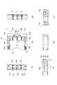
図1は、本発明による一実施形態のブレードコンタクトを備えるベースコネクタを示す斜視外観図である。図2は、前記実施形態によるベースコネクタの斜視外観図である。図2は、図1と反対側からベースコネクタを観ている。図3は、前記実施形態によるベースコネクタと連結されるソケットコネクタの斜視外観図である。図4は、前記実施形態によるソケットコネクタの斜視外観図である。図4は、図3と反対側からソケットコネクタを観ている。 FIG. 1 is a perspective external view showing a base connector having a blade contact according to an embodiment of the present invention. FIG. 2 is a perspective external view of the base connector according to the embodiment. FIG. 2 looks at the base connector from the opposite side of FIG. FIG. 3 is a perspective external view of the socket connector connected to the base connector according to the embodiment. FIG. 4 is a perspective external view of the socket connector according to the embodiment. 4 is a view of the socket connector from the opposite side of FIG.
図5は、前記実施形態によるベースコネクタの外観図及び断面図である。図5(A)はベースコネクタの平面図、図5(B)はベースコネクタの正面図、図5(C)は図5(A)の左側面図、図5(D)は図5(A)の右側面図、図5(E)は図5(A)のQ−Q矢視断面図、図5(F)は図5(A)のR−R矢視断面図である。図6は、前記実施形態によるソケットコネクタの外観図である。図6(A)はソケットコネクタの平面図、図6(B)はソケットコネクタの正面図、図6(C)はソケットコネクタの背面図、図6(D)は図6(A)の左側面図、図6(E)は図6(A)の右側面図である。 FIG. 5 is an external view and a cross-sectional view of the base connector according to the embodiment. 5A is a plan view of the base connector, FIG. 5B is a front view of the base connector, FIG. 5C is a left side view of FIG. 5A, and FIG. 5D is FIG. ) Is a right side view, FIG. 5 (E) is a cross-sectional view taken along the line Q-Q of FIG. 5 (A), and FIG. 5 (F) is a cross-sectional view taken along the line RR of FIG. FIG. 6 is an external view of the socket connector according to the embodiment. 6A is a plan view of the socket connector, FIG. 6B is a front view of the socket connector, FIG. 6C is a rear view of the socket connector, and FIG. 6D is a left side of FIG. 6A. FIG. 6E is a right side view of FIG.
図7は、前記実施形態によるソケットコネクタに適用されるソケットコンタクトの斜視外観図である。図8は、前記実施形態によるソケットコネクタに適用されるソケットコンタクトの斜視外観図である。図8は、図7と反対側からソケットコンタクトを観ている。図9は、前記実施形態による連結状態の両コネクタの縦断面図である。図10は、前記実施形態による連結状態の両コネクタの平面図である。図10は、要部を横断面図としている。図11は、前記実施形態による連結状態の両コネクタの斜視外観図である。 FIG. 7 is a perspective external view of a socket contact applied to the socket connector according to the embodiment. FIG. 8 is a perspective external view of a socket contact applied to the socket connector according to the embodiment. FIG. 8 shows the socket contact from the opposite side of FIG. FIG. 9 is a longitudinal sectional view of both connectors in a connected state according to the embodiment. FIG. 10 is a plan view of both connectors in a connected state according to the embodiment. FIG. 10 is a cross-sectional view of the main part. FIG. 11 is a perspective external view of both connectors in a connected state according to the embodiment.
最初に、本発明の一実施形態によるブレードコンタクトを備えるベースコネクタ及びこのベースコネクタと連結されるソケットコネクタを説明する。図1及び図2において、略直方体状のベースコネクタ1はプリント基板5の取り付け面51に「はんだ」接合により固定されている。ベースコネクタ1の凹部11はプリント基板5の取り付け面51と直交する方向であって取り付け面51から離れる方向(図1の抜去方向X2に相当)に開放し、又、取り付け面51と平行な方向のうち前方Y2に開口している。 First, a base connector including a blade contact according to an embodiment of the present invention and a socket connector connected to the base connector will be described. 1 and 2, the substantially rectangular
図3及び図4に示されるソケットコネクタ2は、ベースコネクタ1の凹部11に対して、取り付け面51と直交する挿抜方向X1・X2に沿って挿抜される。ソケットコネクタ2は概ね前方Y2へ延びる複数のリード線4wを備えている。 The
ソケットコネクタ2をベースコネクタ1から取り外すときに、リード線4wが抜去方向X2以外の方向へ引っ張られることがあるが、その場合に、リード線4wを介する引っ張り力をソケットコネクタ2の抜去方向X2の力に変換して、こじりを生ずることなく、ソケットコネクタ2をスムーズに引き抜くことができる。 When the
図1及び図2において、ベースコネクタ1はベースハウジング1hを備え、ベースハウジング1hは、取り付け面51に沿って固定されるベース12と、ベース12上に立設される左右一対の第1側壁12a・12b及び第1側壁12a・12bに直交する第2側壁12cを備えている。これらベース12、一対の第1側壁12a・12b及び第2側壁12cにより、凹部11は三方が囲まれ、区画されている。 1 and 2, the
図1及び図2において、凹部11の第2側壁12c側には、一対の第1側壁12a・12bに平行な三つの平板状のブレードコンタクト3が配列されている。図5において、ブレードコンタクト3は、第2側壁12cに形成された固定穴121・122に挿嵌された状態で、ベース12及び第2側壁12cにより保持されている。 In FIG. 1 and FIG. 2, three
図9に示されるように、ブレードコンタクト3は、ソケットコンタクト(相手側コンタクト)4と接続されるための略長方形板のコンタクト接続部31と、コンタクト接続部31の基端側に設けられ、第2側壁12c内部に挿嵌される固定部32と、を備えている。コンタクト接続部31における長手方向の一方の板厚面は、凹部11の底面に当接している。固定部32は、プリント基板5に「はんだ」接合されるリード部36を、コンタクト接続部31と相反する方向に延出している。 As shown in FIG. 9, the
図9に示される両コネクタ1・2の連結状態において、ソケットコンタクト4が有する一対の反転アーム45a・45bによって、コンタクト接続部31の両側を挟み接触力が加えられる(図10参照)。 In the coupled state of the
図1及び図2において、一対の第1側壁12a・12bの内側面には、凹部11の底面から抜去方向X2に延びる一対の嵌合溝13a・13bが設けられている。一対の嵌合溝13a・13bは、ソケットコネクタ2の両翼に突出形成された一対の張り出し片23a・23bと嵌まり合う(図3及び図4参照)。 1 and 2, a pair of
図3、図4及び図6に示されるように、一対の張り出し片23a・23bは、下方において隅部が円弧形状をなし、その円弧面は、一対の嵌合溝13a・13bに形成される斜面(図5参照)と滑り合うカム面を形成している。 As shown in FIGS. 3, 4, and 6, the pair of projecting
図1及び図2において、凹部11において対向する一対の第1側壁12a・12bの一対の第1内壁には、互いに対向する一対の嵌合凹部16a・16bが設けられている。一方、ソケットハウジング2hにおいて、相反する位置に形成される一対の第1外壁には、一対の嵌合凸部26a・26bが設けられている(図3、図4及び図6参照)。 1 and 2, a pair of first fitting inner walls of the pair of
そして、一対の嵌合凹部16a・16bに一対の嵌合凸部26a・26bが嵌まり合うことにより、両コネクタ1・2の連結状態が所定の保持力で保持される。このように、一対の嵌合凹部16a・16bと一対の嵌合凸部26a・26bは、リード線4wが延びる方向と直交する方向に互いに係合する一対の第1ロック機構を構成している。 Then, when the pair of fitting
図1及び図2において、一対の嵌合凹部16a・16bは、前記一対の第1内壁に横断面が「C」の字状に窪みを有する形状で形成されている。一対の前記窪みが一対の第1内壁に互いに対向する方向に形成される。一方、図3、図4及び図6に示されるように、一対の嵌合凸部26a・26bは、一対の前記第1外壁に横断面が鋭角の斜面を有する略直角三角形の形状に形成され、一対の突出端が一対の第1外壁に互いに相反する方向に形成されている。 1 and 2, the pair of
一対の嵌合凹部16a・16bをベースハウジング1hの一対の第1内壁に設けることにより、凹部11を区画する一対の第1側壁12a・12bの肉厚を薄くし、ソケットコネクタ2の挿抜が容易なると考えられる。又、一対の嵌合凹部16a・16bをベースハウジング1hの一対の第1内壁に設けることにより、ベースハウジング1hを小型化(実装面積の縮小)できると考えられる。 By providing the pair of
又、図1及び図2において、ベースハウジング1hの凹部11において、リード線4wが延びる方向と相反する方向Y1に形成される第2内壁(第2側壁12cに含まれる)には、二つの溝14a・14bが設けられている。二つの溝14a・14bは、凹部11側に開口されると共に、プリント基板5の取り付け面51と直交する挿抜方向X1・X2に沿って貫通されている。又、二つの溝14a・14bは、ブレードコンタクト3の配列間にそれぞれ設けられている。そして、これらの溝14a・14bの対向する一方の内壁にはそれぞれ第1突起15a・15bが設けられている(図1及び図5参照)。 1 and 2, in the
一方、図3及び図4に示されるように、ソケットハウジング2hにおいてリード線4wが延びる方向と相反する方向Y1(図1参照)に形成される第2外壁には、二つの凸条片24a・24bが設けられている。そして、これらの凸条片24a・24bは、一方の外壁にそれぞれ第2突起25a・25bが設けられている。 On the other hand, as shown in FIGS. 3 and 4, the second outer wall formed in the direction Y1 (see FIG. 1) opposite to the direction in which the
ソケットコネクタ2を凹部11に向けて挿入すると、二つの溝14a・14bに二つの凸条片24a・24bが挿入され、第2突起25a・25bが第1突起15a・15bをそれぞれ乗り越える。ソケットコネクタ2が凹部11に完全に挿入された状態では、第2突起25a・25bが第1突起15a・15bに係止され、ソケットコネクタ2とベースコネクタ1の係合状態が維持される(図11参照)。 When the
このように、二つの溝14a・14bと二つの凸条片24a・24bは、互いに係合する一つ以上の第2ロック機構を構成している。なお、第1突起15a・15b及び第2突起25a・25bも第2ロック機構に含まれる。又、二つの溝14a・14bは方形溝が図示されているが、Uの字状の円弧溝であってもよい。 Thus, the two
図1及び図2において、凹部11に対して互い向かい合う一対の突部18a・18bが設けられている。一方の突部18aは、嵌合溝13aと嵌合凹部16aを区画している。そして、一方の突部18aは、張り出し片23aと嵌合凸部26a間に挿入される。他方の突部18bは、嵌合溝13bと嵌合凹部16bを区画している。そして、他方の突部18bは、張り出し片23bと嵌合凸部26b間に挿入される。 1 and 2, a pair of
図1、図2及び図5において、金属製の補強部材としての一対の補強タブ17a・17bが、ベースハウジング1hの前下部に形成された圧入溝に圧入されて、一部がベースハウジング1hの底面に露出し、プリント基板5の取り付け面51に「はんだ」接合されている。 In FIG. 1, FIG. 2 and FIG. 5, a pair of reinforcing
図6において、ソケットコネクタ2の前部には、ソケットハウジング2hの押圧面としての上面にブレードコンタクト3の位置に対応して突出する凸部22cと、ソケットハウジング2hの両側面にそれぞれ突出する上述した一対の張り出し片23a・23bを備えている。凸部22cの表面を押すことにより、ソケットコネクタ2をベースコネクタ1に装着できる。 In FIG. 6, at the front portion of the
図3及び図4において、ソケットコネクタ2は、略直方体状のソケットハウジング2hを有している。ソケットハウジング2hには、リード線4wの延びる方向に収容穴21が設けられている。ソケットハウジング2hには、複数の収容穴21が並べて設けられている。各収容穴21には、それぞれリード線4wの端部に圧着されたソケットコンタクト4が収容されている(図9参照)。 3 and 4, the
図7及び図8に示されるソケットコンタクト4はブレードコンタクト3と接続される。ソケットコンタクト4は、リード線4wが接続される長尺状の圧着部47と、圧着部47の基端側に設けられ、ブレードコンタクト3に接続されるコンタクト接続部45と、を備えている。 The
コンタクト接続部45は、平板状のコンタクト本体41と、コンタクト本体41の基端42側から延出する略平行な一対の伸長アーム43a・43bと、一対の伸長アーム43a・43bの先端からコンタクト本体41に向って延出しかつ先端同士が結合された略平行な一対の反転アーム45a・45bを備えている。そして、一対の反転アーム45a・45bには、互いに対向しブレードコンタクト3が挿入可能な一対の接点46a・46bが設けられている。 The
図7及び図8に示されるように、一対の反転アーム45a・45bは、先端部が相互に結合されている。一対の反転アーム45a・45bの先端部は、予め相互に結合されて結合部45cが形成されており、折り曲げ加工により一対の反転アーム45a・45bが形成されている。 As shown in FIGS. 7 and 8, the tip ends of the pair of
図7又は図8に示されるように、一対の反転アーム45a・45bは、折り返し部44a・44b側の板厚面に互いに対向する半球状の突起からなる一対の接点46a・46bが設けられている。これら一対の接点46a・46b間に平板状のブレードコンタクト3(図9参照)を挿入可能としている。一対の反転アーム45a・45bから一対の伸長アーム43a・43bに向けて、一対の接点46a・46b間にコンタクト接続部31が挿入される(図9及び図10参照) As shown in FIG. 7 or FIG. 8, the pair of reversing
一対の接点46a・46b間にコンタクト接続部31が挿入されると、一対の接点46a・46bが押し広げられる。つまり、一対の伸長アーム43a・43b及び反転アーム45a・15bの折り返し部44a・44b側が押し広げられる。一対の伸長アーム43a・43b及び反転アーム45a・45bの折り返し部44a・44b側と反対側は、相互に結合されているので、弾性力によりコンタクト接続部31の両面に適切な接触力を加えることができる。 When the
このソケットコンタクト4は、従来のソケットコンタクトに比べ強い接触力をブレードコンタクト3に加えることでき、しかも、従来のソケットコンタクトより小型化できる。又、ソケットコンタクト4は、1.2mm程度の狭ピッチでも並列配置することができる。このようなソケットコンタクト4が適用されるソケットコネクタ2は、低背化・小型化を可能としている。 The
図7及び図8において、ソケットコンタクト4は、リード線4wを圧着する圧着部47が設けられている。そして、圧着部47は、リード線4wの被覆部に圧着されるインシュレーショングリップ47aと、リード線4wの芯線に圧着されるコンダクタグリップ47bを備えている。リード線4wの一方の端末が圧着されて、収容穴21に挿入される(図9参照)。 7 and 8, the
図9において、弾性突起からなるランス41cは、収容穴21に連通して外面に開口している係合穴に係止しており、ソケットコンタクト4が収容穴21から抜け出すのを防止している。ソケットコネクタ2は、一対の接点46a・46bがベースコネクタ1に対向する部分が開口され、ブレードコンタクト3が一対の接点46a・46bに挿入可能となっている(図10参照)。 In FIG. 9, a
図9において、ブレードコンタクト3は、略長方形をなすコンタクト接続部31と、コンタクト接続部31の基端側に設けられる固定部32を備えている。固定部32は、第2側壁12cに形成された固定穴121・122(図5参照)に挿嵌された状態で、第2側壁12c内部に保持されている。そして、固定部32は、第2側壁12c内部に圧入される圧入部33と、圧入部33に対向し、かつ第2側壁12c内部に挿入される固定アーム34と、圧入部33と固定アーム34の基端同士を連結する連結脚35と、を備えている。 In FIG. 9, the
図9において、圧入部33は、第2側壁12cに形成された固定穴122(図5参照)に圧入された状態で、第2側壁12c内部に保持されている。固定アーム34は、第2側壁12cに形成された固定穴122(図5参照)に挿入された状態で、第2側壁12c内部に保持されている。又、連結脚35は、固定穴121と固定穴122を連通するスリット状の溝に挿入されている。 In FIG. 9, the press-
図9において、ブレードコンタクト3の固定部32は、このように構成されているので、ブレードコンタクト3のコンタクト接続部31に相手側コンタクトが挿入されるときは、圧入部33を支点とする第1の方向に作用する回転モーメントは、コンタクト接続部31が凹部11の底面(図1参照)に当接して、ブレードコンタクト3の姿勢が維持される。一方、ブレードコンタクト3のコンタクト接続部31から相手側コンタクトが抜去されるときは、圧入部33を支点とする第2の方向に作用する回転モーメントは、固定アーム34により阻止され、ブレードコンタクト3の姿勢が維持される。 In FIG. 9, the fixing
又、圧入部33は、固定アーム34に向う側に第2側壁12c内部に係止される圧入突起33aを備えている。圧入突起33aは山脈状に突出する微細突起であってよく、合成樹脂で成形された第2側壁12c内部を食い破るように圧入される。そして、互いに対向する固定アーム34と圧入部33とは、第2側壁12c内部を挟むことにより、ブレードコンタクト3の姿勢が強固に維持される。 Further, the press-
図9において、コンタクト接続部31の上縁31a及び前縁31bには、面取りが形成され、ソケットコンタクト4の挿入を容易にしている。そして、コンタクト接続部31における長手方向の一方の板厚面は、凹部11の底面に当接している。 In FIG. 9, chamfering is formed on the
本発明によるブレードコンタクトは、対向する一対の第1側壁と、この一対の第1側壁と直交する第2側壁とで凹部を形成するベースコネクタに対して、第2側壁から凹部に向って挿嵌され、相手側コンタクトと接続されるためのコンタクト接続部が凹部の底面に当接する構造としたので、従来のように、ブレードコンタクトをベースの底面から圧入して、ブレードコンタクトの姿勢を保持することなく、凹部の底面と第2側壁でブレードコンタクトの姿勢を保持できる。したがって、ベースの肉厚が薄くでき、ベースコネクタの更なる低背化が実現できる。例えば、ベースコネクタの高さを、従来の「6.1」mmから「1.5」mmに低背化できた。 The blade contact according to the present invention is inserted from the second side wall toward the concave portion with respect to the base connector in which the concave portion is formed by the pair of first side walls facing each other and the second side wall orthogonal to the pair of first side walls. Since the contact connecting part to be connected to the mating contact is in contact with the bottom surface of the recess, the blade contact is press-fitted from the bottom surface of the base to maintain the blade contact posture as before. The blade contact posture can be maintained by the bottom surface of the recess and the second side wall. Therefore, the thickness of the base can be reduced, and the base connector can be further reduced in height. For example, the height of the base connector can be lowered from the conventional “6.1” mm to “1.5” mm.
本発明によるブレードコンタクト3を備えるベースコネクタ1と、上述のソケットコンタクト4を備えるソケットコネクタ2が連結されたコネクタ3cn(図11参照)は、大変小型・低背であり、近年の小型化した携帯用電子機器に適合している。 The connector 3cn (see FIG. 11) to which the
1 ベースコネクタ
3 ブレードコンタクト
4 ソケットコンタクト(相手側コンタクト)
5 プリント基板
11 凹部
12a・12b 一対の第1側壁
12c 第2側壁
31 コンタクト接続部
32 固定部
33 圧入部
33a 圧入突起
34 固定アーム
35 連結脚
36 リード部1
DESCRIPTION OF
Claims (2)
Translated fromJapanese相手側コンタクトと接続されるための略長方形板のコンタクト接続部と、このコンタクト接続部の基端側に設けられ、前記第2側壁の内部に挿嵌される固定部と、を備え、
前記固定部は、前記第2側壁の内部に圧入される圧入部と、この圧入部に対向し、かつ前記第2側壁の内部に挿入される固定アームと、前記圧入部と前記固定アームの基端同士を連結する連結脚と、を有し、
前記圧入部は、前記固定アームに向う側に前記第2側壁の内部に係止される圧入突起を有し、
前記コンタクト接続部における長手方向の一方の板厚面は、前記凹部の底面に当接するブレードコンタクト。The pair of first sidewalls on the second sidewall side of the recess in the substantially rectangular parallelepiped base connector having a recess surrounded on three sides by a pair of first sidewalls facing each other and a second sidewall orthogonal to the first sidewalls Blade contacts arranged substantially in parallel with
A contact connection portion of a substantially rectangular plate to be connected to the mating contact, anda fixing portion provided on the proximal end side of the contact connection portion andfitted into the second side wall ,
The fixed portion includes a press-fit portion that is press-fitted into the second side wall, a fixed arm that is opposed to the press-fit portion and is inserted into the second side wall, and a base between the press-fit portion and the fixed arm. A connecting leg for connecting the ends,
The press-fitting part has a press-fitting protrusion that is locked inside the second side wall on the side facing the fixed arm,
One plate thickness surface in the longitudinal direction of the contact connecting portion is a blade contact that contacts the bottom surface of the recess.
Priority Applications (3)
| Application Number | Priority Date | Filing Date | Title |
|---|---|---|---|
| JP2004317952AJP4115983B2 (en) | 2004-11-01 | 2004-11-01 | Blade contact |
| CNB2005101172364ACN100550527C (en) | 2004-11-01 | 2005-10-31 | Dock connector |
| US11/261,716US7112102B2 (en) | 2004-11-01 | 2005-10-31 | Base connector |
Applications Claiming Priority (1)
| Application Number | Priority Date | Filing Date | Title |
|---|---|---|---|
| JP2004317952AJP4115983B2 (en) | 2004-11-01 | 2004-11-01 | Blade contact |
Publications (2)
| Publication Number | Publication Date |
|---|---|
| JP2006128034A JP2006128034A (en) | 2006-05-18 |
| JP4115983B2true JP4115983B2 (en) | 2008-07-09 |
Family
ID=36262644
Family Applications (1)
| Application Number | Title | Priority Date | Filing Date |
|---|---|---|---|
| JP2004317952AExpired - LifetimeJP4115983B2 (en) | 2004-11-01 | 2004-11-01 | Blade contact |
Country Status (3)
| Country | Link |
|---|---|
| US (1) | US7112102B2 (en) |
| JP (1) | JP4115983B2 (en) |
| CN (1) | CN100550527C (en) |
Cited By (3)
| Publication number | Priority date | Publication date | Assignee | Title |
|---|---|---|---|---|
| US11005215B2 (en) | 2018-07-03 | 2021-05-11 | Molex, Llc | Connector and connector assembly |
| US11025009B2 (en) | 2018-12-27 | 2021-06-01 | Molex, Llc | Circuit substrate mounted cable connector |
| US11374358B2 (en) | 2019-07-01 | 2022-06-28 | Amphenol Fci Asia Pte. Ltd. | Wire to board connector with low height |
Families Citing this family (38)
| Publication number | Priority date | Publication date | Assignee | Title |
|---|---|---|---|---|
| WO2008015817A1 (en)* | 2006-07-31 | 2008-02-07 | Mitsumi Electric Co., Ltd. | Connector for connecting electronic component |
| JP2009181769A (en) | 2008-01-30 | 2009-08-13 | Kyocera Elco Corp | Connector, plug connector, and portable terminal |
| JP5086853B2 (en)* | 2008-03-18 | 2012-11-28 | 日本圧着端子製造株式会社 | Socket contact |
| IT1391120B1 (en)* | 2008-10-02 | 2011-11-18 | Techno S R L | SOCKET AND ELECTRIC CONNECTION STRUCTURE OF TWO OR THREE-POLE SOCKETS. |
| JP5203989B2 (en)* | 2009-01-28 | 2013-06-05 | タイコエレクトロニクスジャパン合同会社 | Electrical connector |
| US8096825B2 (en)* | 2009-03-25 | 2012-01-17 | Belkin International Inc. | Electrical coupler system and method for manufacture thereof |
| JP5247904B2 (en)* | 2009-04-16 | 2013-07-24 | ヒロセ電機株式会社 | Electrical connector assembly |
| JP5385022B2 (en)* | 2009-06-16 | 2014-01-08 | モレックス インコーポレイテド | Wire-to-board connector |
| CN201498712U (en)* | 2009-06-24 | 2010-06-02 | 富士康(昆山)电脑接插件有限公司 | electrical connector |
| CN102208726B (en)* | 2010-03-29 | 2013-05-08 | 富士康(昆山)电脑接插件有限公司 | Cable connector assembly |
| TWM391764U (en)* | 2010-04-16 | 2010-11-01 | Hon Hai Prec Ind Co Ltd | Electrical connector |
| JP2012003874A (en)* | 2010-06-15 | 2012-01-05 | Fujitsu Ltd | Connector, receptacle connector and plug connector |
| CN102957042B (en)* | 2011-08-31 | 2014-11-26 | 昆山联滔电子有限公司 | Socket connector and connector assembly |
| US20130090018A1 (en)* | 2011-10-06 | 2013-04-11 | Cheng Uei Precision Industry Co., Ltd. | Cable connector |
| TWI427841B (en)* | 2011-10-18 | 2014-02-21 | Hongwen Hwang | Li battery and connector thereof |
| CN104221227B (en)* | 2012-03-27 | 2016-08-24 | 日本航空电子工业株式会社 | Wire-to-board connector |
| KR101292746B1 (en)* | 2012-07-04 | 2013-08-02 | 한국몰렉스 주식회사 | Offset type wire to board connector |
| US9246242B2 (en)* | 2012-09-05 | 2016-01-26 | Hubbell Incorporated | Push wire connector having a rotatable release member |
| JP5903726B2 (en)* | 2012-12-27 | 2016-04-13 | ヒロセ電機株式会社 | Cable connector and connector device having the cable connector |
| TWI489697B (en)* | 2013-08-09 | 2015-06-21 | Wistron Corp | Wire to board connector assembly and board connector thereof |
| JP6249676B2 (en)* | 2013-08-21 | 2017-12-20 | 宏致電子股▲ふん▼有限公司Aces Electronics Co.,Ltd. | Electrical connector |
| TWM470405U (en)* | 2013-09-27 | 2014-01-11 | Bellwether Electronic Corp | Electrical connector |
| CN103794945B (en)* | 2014-02-25 | 2016-04-13 | 实盈电子(东莞)有限公司 | Electric connector |
| US9293863B2 (en)* | 2014-06-16 | 2016-03-22 | Apple Inc. | Mountable open top connector having a retainer |
| US9337573B2 (en)* | 2014-07-01 | 2016-05-10 | Foxconn Interconnect Technology Limited | Electrical connector assembly with jumper element assembled thereon |
| US9270053B2 (en)* | 2014-07-01 | 2016-02-23 | Foxconn Interconnect Technology Limited | Electrical connector assembly with jumper element assembled thereon |
| JP6254542B2 (en)* | 2015-02-10 | 2017-12-27 | ヒロセ電機株式会社 | Connector device having a cable connector |
| JP6594248B2 (en)* | 2016-04-04 | 2019-10-23 | ヒロセ電機株式会社 | Power connector device |
| DE102016110050B4 (en)* | 2016-05-31 | 2020-01-23 | Endress+Hauser SE+Co. KG | Plug connection for electrical contacting of a printed circuit board |
| CN206004039U (en) | 2016-08-04 | 2017-03-08 | 富士康(昆山)电脑接插件有限公司 | Electric connector and combinations thereof |
| CN107565237B (en)* | 2017-05-12 | 2020-04-24 | 番禺得意精密电子工业有限公司 | Electrical connector |
| US10404008B2 (en)* | 2017-10-06 | 2019-09-03 | Te Connectivity Corporation | Connector system with receptacle and plug connectors having complimentary angled connector platforms |
| WO2020014449A1 (en) | 2018-07-12 | 2020-01-16 | Samtec, Inc. | Cable connector system |
| JP7039435B2 (en)* | 2018-10-05 | 2022-03-22 | モレックス エルエルシー | Connector assembly |
| TWM601912U (en)* | 2019-03-26 | 2020-09-21 | 英屬開曼群島商鴻騰精密科技股份有限公司 | Receptacle connector |
| CN211295428U (en)* | 2020-02-28 | 2020-08-18 | 厦门广泓工贸有限公司 | A patch connector |
| CN117293575A (en)* | 2020-03-26 | 2023-12-26 | 上海莫仕连接器有限公司 | Electric connection device and terminal |
| US20250112404A1 (en)* | 2023-09-29 | 2025-04-03 | Eaton Intelligent Power Limited | Connector arm lock for plug-in type electrical wiring management devices |
Family Cites Families (14)
| Publication number | Priority date | Publication date | Assignee | Title |
|---|---|---|---|---|
| US5575674A (en) | 1994-07-29 | 1996-11-19 | The Whitaker Corporation | Connector adapted for hermaphroditic construction |
| JPH08213082A (en) | 1994-10-21 | 1996-08-20 | Whitaker Corp:The | Electric terminal and electric connector using the same |
| US5641308A (en) | 1995-04-28 | 1997-06-24 | Molex Incorporated | Electrical connector |
| US5727961A (en) | 1996-04-30 | 1998-03-17 | The Whitaker Corporation | Two-way transversely matable electrical connector |
| WO1997045896A1 (en)* | 1996-05-30 | 1997-12-04 | The Whitaker Corporation | Surface mountable electrical connector |
| US6135781A (en) | 1996-07-17 | 2000-10-24 | Minnesota Mining And Manufacturing Company | Electrical interconnection system and device |
| TW399810U (en)* | 1997-03-13 | 2000-07-21 | Hon Hai Prec Ind Co Ltd | Multi-direction connector |
| US6039610A (en)* | 1998-04-08 | 2000-03-21 | The Whitaker Corporation | Multiple circuit fork contact connector |
| TW444940U (en)* | 2000-03-03 | 2001-07-01 | Molex Inc | Battery connector |
| JP3386783B2 (en)* | 2000-07-14 | 2003-03-17 | 日本圧着端子製造株式会社 | Electrical connector and socket connector |
| JP3614768B2 (en)* | 2000-10-20 | 2005-01-26 | タイコエレクトロニクスアンプ株式会社 | Battery connector |
| US6506081B2 (en)* | 2001-05-31 | 2003-01-14 | Tyco Electronics Corporation | Floatable connector assembly with a staggered overlapping contact pattern |
| US6848950B2 (en)* | 2003-05-23 | 2005-02-01 | Fci Americas Technology, Inc. | Multi-interface power contact and electrical connector including same |
| JP2005196975A (en)* | 2003-12-26 | 2005-07-21 | Jst Mfg Co Ltd | connector |
- 2004
- 2004-11-01JPJP2004317952Apatent/JP4115983B2/ennot_activeExpired - Lifetime
- 2005
- 2005-10-31USUS11/261,716patent/US7112102B2/enactiveActive
- 2005-10-31CNCNB2005101172364Apatent/CN100550527C/enactiveActive
Cited By (4)
| Publication number | Priority date | Publication date | Assignee | Title |
|---|---|---|---|---|
| US11005215B2 (en) | 2018-07-03 | 2021-05-11 | Molex, Llc | Connector and connector assembly |
| US11509094B2 (en) | 2018-07-03 | 2022-11-22 | Molex, Llc | Connector and connector assembly |
| US11025009B2 (en) | 2018-12-27 | 2021-06-01 | Molex, Llc | Circuit substrate mounted cable connector |
| US11374358B2 (en) | 2019-07-01 | 2022-06-28 | Amphenol Fci Asia Pte. Ltd. | Wire to board connector with low height |
Also Published As
| Publication number | Publication date |
|---|---|
| JP2006128034A (en) | 2006-05-18 |
| CN1770562A (en) | 2006-05-10 |
| US20060094306A1 (en) | 2006-05-04 |
| CN100550527C (en) | 2009-10-14 |
| US7112102B2 (en) | 2006-09-26 |
Similar Documents
| Publication | Publication Date | Title |
|---|---|---|
| JP4115983B2 (en) | Blade contact | |
| JP4328709B2 (en) | Electrical connector | |
| JP4020907B2 (en) | Socket contact | |
| JP4287825B2 (en) | Board connector | |
| JP4620587B2 (en) | Electrical connector | |
| US7637787B2 (en) | Audio jack connector | |
| JP3173283U (en) | Electrical connector | |
| CN102751601B (en) | Electric connector used for circuit substrate | |
| JP2009206059A (en) | Electric connector | |
| JP2007503693A (en) | Board-to-board electrical connector assembly | |
| JP2000277196A (en) | Electric connector | |
| JP2008243689A (en) | connector | |
| JP2010157368A (en) | Electrical connector | |
| JP2009517802A (en) | Electrical connector | |
| JP2004207165A (en) | Electric connector | |
| JP5444285B2 (en) | Circuit board electrical connector | |
| JP2007095371A (en) | Electrical connector | |
| JP2004119374A (en) | Electrical connector for card | |
| JP4482568B2 (en) | Electrical connector | |
| JP2010157367A (en) | Electrical connector | |
| US7077674B2 (en) | Board attachment type electrical connector | |
| US6364717B1 (en) | Audio jack with a controlled normal force for retaining a mating plug | |
| JP3087810B2 (en) | Multi-pole flat connector plug | |
| JPH0684682U (en) | Wire connector | |
| CN2305793Y (en) | Board-to-Board Connector Assemblies |
Legal Events
| Date | Code | Title | Description |
|---|---|---|---|
| A977 | Report on retrieval | Free format text:JAPANESE INTERMEDIATE CODE: A971007 Effective date:20071214 | |
| A131 | Notification of reasons for refusal | Free format text:JAPANESE INTERMEDIATE CODE: A131 Effective date:20071218 | |
| A521 | Request for written amendment filed | Free format text:JAPANESE INTERMEDIATE CODE: A523 Effective date:20080213 | |
| TRDD | Decision of grant or rejection written | ||
| A01 | Written decision to grant a patent or to grant a registration (utility model) | Free format text:JAPANESE INTERMEDIATE CODE: A01 Effective date:20080408 | |
| A61 | First payment of annual fees (during grant procedure) | Free format text:JAPANESE INTERMEDIATE CODE: A61 Effective date:20080416 | |
| FPAY | Renewal fee payment (event date is renewal date of database) | Free format text:PAYMENT UNTIL: 20110425 Year of fee payment:3 | |
| R150 | Certificate of patent or registration of utility model | Ref document number:4115983 Country of ref document:JP Free format text:JAPANESE INTERMEDIATE CODE: R150 Free format text:JAPANESE INTERMEDIATE CODE: R150 | |
| FPAY | Renewal fee payment (event date is renewal date of database) | Free format text:PAYMENT UNTIL: 20110425 Year of fee payment:3 | |
| FPAY | Renewal fee payment (event date is renewal date of database) | Free format text:PAYMENT UNTIL: 20120425 Year of fee payment:4 | |
| R250 | Receipt of annual fees | Free format text:JAPANESE INTERMEDIATE CODE: R250 | |
| FPAY | Renewal fee payment (event date is renewal date of database) | Free format text:PAYMENT UNTIL: 20130425 Year of fee payment:5 | |
| R250 | Receipt of annual fees | Free format text:JAPANESE INTERMEDIATE CODE: R250 | |
| FPAY | Renewal fee payment (event date is renewal date of database) | Free format text:PAYMENT UNTIL: 20140425 Year of fee payment:6 | |
| R250 | Receipt of annual fees | Free format text:JAPANESE INTERMEDIATE CODE: R250 | |
| R250 | Receipt of annual fees | Free format text:JAPANESE INTERMEDIATE CODE: R250 | |
| R250 | Receipt of annual fees | Free format text:JAPANESE INTERMEDIATE CODE: R250 | |
| R250 | Receipt of annual fees | Free format text:JAPANESE INTERMEDIATE CODE: R250 | |
| R250 | Receipt of annual fees | Free format text:JAPANESE INTERMEDIATE CODE: R250 | |
| R250 | Receipt of annual fees | Free format text:JAPANESE INTERMEDIATE CODE: R250 | |
| R250 | Receipt of annual fees | Free format text:JAPANESE INTERMEDIATE CODE: R250 | |
| R250 | Receipt of annual fees | Free format text:JAPANESE INTERMEDIATE CODE: R250 | |
| R250 | Receipt of annual fees | Free format text:JAPANESE INTERMEDIATE CODE: R250 | |
| R250 | Receipt of annual fees | Free format text:JAPANESE INTERMEDIATE CODE: R250 | |
| R250 | Receipt of annual fees | Free format text:JAPANESE INTERMEDIATE CODE: R250 | |
| R250 | Receipt of annual fees | Free format text:JAPANESE INTERMEDIATE CODE: R250 | |
| EXPY | Cancellation because of completion of term |