JP4114194B2 - Head-up display device - Google Patents
Head-up display deviceDownload PDFInfo
- Publication number
- JP4114194B2 JP4114194B2JP30801498AJP30801498AJP4114194B2JP 4114194 B2JP4114194 B2JP 4114194B2JP 30801498 AJP30801498 AJP 30801498AJP 30801498 AJP30801498 AJP 30801498AJP 4114194 B2JP4114194 B2JP 4114194B2
- Authority
- JP
- Japan
- Prior art keywords
- liquid crystal
- crystal display
- display element
- display device
- crystal cell
- Prior art date
- Legal status (The legal status is an assumption and is not a legal conclusion. Google has not performed a legal analysis and makes no representation as to the accuracy of the status listed.)
- Expired - Lifetime
Links
- 239000004973liquid crystal related substanceSubstances0.000claimsdescription81
- 210000002858crystal cellAnatomy0.000claimsdescription33
- 230000010287polarizationEffects0.000claimsdescription19
- 239000000758substrateSubstances0.000claimsdescription13
- 230000003287optical effectEffects0.000claimsdescription10
- 239000011521glassSubstances0.000claimsdescription8
- 238000010586diagramMethods0.000description3
- 230000000694effectsEffects0.000description1
Images


Landscapes
- Liquid Crystal (AREA)
- Devices For Indicating Variable Information By Combining Individual Elements (AREA)
Description
Translated fromJapanese【0001】
【発明の属する技術分野】
本発明は、液晶表示素子を有するヘッドアップディスプレイ装置に関するものである。
【0002】
【従来の技術】
従来より、図6及び図7に示すような車両用表示装置1がある。斯かる車両用表示装置1は、液晶表示素子2,光源3及びリフレクタ4をケース5に収容したものであり、車両のダッシュボード6に埋設されている。この車両用表示装置1はフロントガラス7に表示像aを投影し運転者8に虚像9を視認させるものであり、一般にヘッドアップディスプレイと称されている。
液晶表示素子2は透明電極膜を付けた一対の透光性基板に液晶を封入した液晶セル10の前後面に前側偏光板11,後側偏光板12を貼り合わせたものである。前側偏光板11の偏光方向(Y軸方向)と後側偏光板12の偏光方向(X軸方向)とは垂直になっている。液晶表示素子2は受光型表示素子であり、液晶表示素子2の後方に光源3及びこの光源3の光を反射させるリフレクタ4を設け液晶表示素子2を後方から照明し、良好な視認性を得るようにしている。
【0003】
【発明が解決しようとする課題】
液晶セル10内の液晶の粘性は温度によって変化するため、適正なコントラスト比が得られるように駆動電圧を調整している。例えば、ケース5内に温度センサを取付けて、この温度センサの出力に基づいて、液晶セル10の温度が高いときは駆動電圧を下げ、温度が低いときは駆動電圧を上げるように構成している。
しかし、液晶セル10の温度が著しく上昇すると駆動電圧を調整しても所望のコントラスト比が得られない。ところが、ケース5の開口13から太陽光bが入射する場合があり、前側偏光板11が太陽光bを吸収して発熱しこの熱が液晶セル10に伝わり、液晶セル10の温度が過度に上昇してしまう虞があった。特に、表示像aを拡大する凸レンズ等の光学部材14が設けられた表示装置では、光学部材14により太陽光bが前側偏光板11の狭い範囲に集められるため温度上昇が著しい。本発明は、液晶セルの温度上昇を抑制し適正なコントラスト比が得られるヘッドアップディスプレイ装置を提供するものである。
【0004】
【課題を解決するための手段】
本発明は、前記課題を解決するため、一対の透光性基板に液晶を封入した液晶セルと、前記液晶セルの前面に配設される第一の前側偏光部材と、前記液晶セルの後面に配設される後側偏光部材と、を有する液晶表示素子と、前記液晶表示素子の後方に配設され前記液晶表示素子を照明する光源と、前記第一の前側偏光部材と略同じ方向の偏光方向を有し、ガラス基板に貼着され、前記液晶表示素子の前方に配設される第二の前側偏光部材と、を有するものである。
【0005】
また、本発明は、前記第二の前側偏光部材は、反射型偏光フィルムであるものである。
【0006】
また、本発明は、前記液晶表示素子の表示像を拡大する光学部材を有するものである。
【0007】
また、本発明は、前記液晶表示素子は、赤(R)または緑(G)の画素よりも多数の青(B)の画素を有するものである。
【0008】
【発明の実施の形態】
以下、本発明の一実施形態を添付の図面に基づいて説明する。なお、図1,図3及び図4においては紙面と垂直な方向をY軸方向、紙面の横方向をX軸方向、紙面の縦方向をZ軸方向として説明する。図1及び図2は実施形態を示す図である。
【0009】
15は液晶表示素子であり、この液晶表示素子15は一対の透光性基板に液晶が封入された液晶セル16,前側偏光板17(第一の前側偏光部材)及び後側偏光板18(後側偏光部材)からなるものである。前側偏光板17の偏光方向はY軸方向となっており、後側偏光板18の偏光方向はX軸方向となっている。
19はランプ(光源)であり、このランプ19は液晶表示素子15の後方に配設され液晶表示素子15を照明する。20はリフレクタであり、このリフレクタ20はランプ19が発する光を液晶表示素子15に反射させる。リフレクタ20はおわん形となっている。
【0010】
21は反射型偏光フィルム(第二の前側偏光部材)である。この反射型偏光フィルム21は例えば商品名「HMF(Heat Management Filter)」(住友スリーエム株式会社製)からなるものである。反射型偏光フィルム21の偏光方向は前側偏光板17の偏光方向と同じ方向(Y軸方向)となっている。反射型偏光フィルム21はガラス基板22に貼着され、液晶表示素子15の前方に配設されている。
【0011】
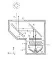
23は平面反射鏡であり、この平面反射鏡23は液晶表示素子15に対して略45度の角度で配置されており表示像aを後述する凹面反射鏡に反射させる。24は凹面反射鏡(光学部材)であり、この凹面反射鏡24は表示像aを車両のフロントガラス(図示しない)に向けて反射させる。凹面反射鏡24の反射面25は凹面となっており、表示像aを拡大することができる。26はケースであり、このケース26には表示像aを出射する開口27が形成されている。液晶表示素子15,ランプ19,リフレクタ20,反射型偏光フィルム21,平面反射鏡23及び凹面反射鏡24はケース26に収容される。
【0012】
次に、図2を用いて反射型偏光フィルム21の作用を説明する。反射型偏光フィルム21はY軸方向の光を通過させ、X軸方向の光を反射させる。つまり、通常の偏光板は偏光方向(Y軸方向)と直交する方向(X軸方向)の光を吸収するが、反射型偏光フィルム21はX軸方向の光を反射することができる。
従って、太陽が略真上にある時は太陽光bがケース26の開口27から入射し凹面反射鏡25及び平面反射鏡23に反射されて液晶表示素子15に照射されるが、太陽光bは反射型偏光フィルム21に吸収されることがない。反射型偏光フィルム21に反射された光は、平面反射鏡23及び凹面反射鏡25に反射され、開口27からケース26に射出される。
【0013】
そして、反射型偏光フィルム21を通過した太陽光bは、Y軸方向の偏光であるので、前側偏光板17を通過し液晶セル16内で90度捩じられてX軸方向の偏光となり、後側偏光板18も通過する。従って、太陽光bは各偏光板17,18に吸収されることがなく、液晶セル16の温度は上昇しない。
一方、液晶表示素子15の前側偏光板17の偏光方向と反射型偏光フィルム21の偏光方向とは同じ方向(Y軸方向)となっているため、表示像aは反射型偏光フィルム21を通過できる。
【0014】
なお、第二の前側偏光部材は通常の偏光板であっても良いが、X軸方向の光を吸収し発熱するため、この熱によりケース26内の空気が暖められて液晶セル16の温度が上がるので、第二の前側偏光部材は反射型偏光フィルム21が望ましい。
【0015】
図3は参考例を示す図である。参考例においては、実施形態と同一の箇所には同一の符号を付しその詳細な説明を省略する。
【0016】
液晶表示素子28は、液晶セル16の後面に後側偏光板18を貼着し前面に反射型偏光フィルム21を貼着したものである。29は凸レンズ(光学部材)であり、この凸レンズ29は表示像aを拡大させることができる。
太陽が略真上にある時は太陽光bがケース26の開口27から入射し、液晶表示素子28に照射されるが、第一の実施の形態と同様に反射型偏光フィルム21の作用により、太陽光bは各偏光板17,18に吸収されることがなく、液晶セル16の温度は上昇しない。反射型偏光フィルム21に反射された光は、開口27からケース26に射出される。
【0017】
図4は他の参考例を示す図である。他の参考例においては、実施形態と同一の箇所には同一の符号を付しその詳細な説明を省略する。
【0018】
液晶表示素子30は、反射型偏光フィルム21,ガラス基板22,液晶セル16,後側偏光板18及びガラス基板31からなるものである。後側偏光板18はガラス基板31に貼着され、液晶セル16から所定間隔d1をあけて配置されている。反射型偏光フィルム21はガラス基板22に貼着され、液晶セル16から所定間隔d2をあけて配置されている。
太陽が略真上にある時は太陽光bがケース26の開口27から入射し、液晶表示素子30に照射されるが、第一の実施の形態と同様に反射型偏光フィルム21の作用により、太陽光bは反射型偏光フィルム21,後側偏光板18に吸収されることがなく、液晶セル16の温度は上昇しない。
【0019】
後側偏光板18の偏光方向はX軸方向であり、X軸方向の光を通過させY軸方向の光を吸収する。ランプ19の光はX軸及びY軸方向の光を含んでいるため、後側偏光板18はY軸方向の光を吸収し発熱するため、この熱によりケース26内の空気が暖められるが、後側偏光板18は液晶セル16から所定間隔d1をあけて配置されており液晶セル16に接していないため、液晶セル16の温度上昇は僅かである。
【0020】
なお、前側偏光部材は通常の偏光板であっても良いが、X軸方向の光を吸収し発熱するため、この熱によりケース26内の空気が暖められて液晶セル16の温度が上がるので、前側偏光部材は反射型偏光フィルム21が望ましい。
【0021】
実施形態によれば、太陽光bに因る液晶セル16の温度上昇を緩和することができ、液晶表示素子15,28,30の適正なコントラストを得ることができる。特に、表示像aを拡大するため凹面反射鏡24または凸レンズ29等の光学部材を設けたヘッドアップディスプレイ装置において、太陽光bが光学部材により集光されるため、本発明を適用することが効果的である。
なお、本明細書において、「前方」とは表示像aが進む向きを意味する。前側偏光部材は液晶表示素子15の前方に配置すれば良く、例えば、実施形態において、反射型偏光フィルム21(第二の前側偏光部材)を平面反射鏡23と凹面反射鏡24との間に配置しても良い。
【0022】
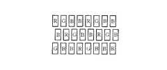
また、一般にランプ19の光は青色の光が弱くいため、図5に示すように、液晶表示素子15,28,30には、赤(R)または緑(G)の画素よりも2倍の青(B)の画素を設けることが望ましい。
【0023】
【発明の効果】
本発明は、一対の透光性基板に液晶を封入した液晶セルと、前記液晶セルの前面に配設される第一の前側偏光部材と、前記液晶セルの後面に配設される後側偏光部材と、を有する液晶表示素子と、前記液晶表示素子の後方に配設され前記液晶表示素子を照明する光源と、前記第一の前側偏光部材と略同じ方向の偏光方向を有し、ガラス基板に貼着され、前記液晶表示素子の前方に配設される第二の前側偏光部材と、を有するものであり、液晶セルの温度上昇を抑制し適正なコントラスト比を得ることができる。
【図面の簡単な説明】
【図1】 本発明の実施形態を示す断面図。
【図2】 同上実施形態を示す要部斜視図。
【図3】参考例を示す断面図。
【図4】他の参考例を示す断面図。
【図5】 本発明の液晶表示素子の画素の説明図。
【図6】 従来例を示す側面図。
【図7】 同上従来例を示す断面図。
【符号の説明】
15 液晶表示素子
16 液晶セル
17 前側偏光板(第一の前側偏光部材)
18 後側偏光板(後側偏光部材)
19 ランプ(光源)
21 反射型偏光フィルム(第二の前側偏光部材)
24 凹面反射鏡(光学部材)
28 液晶表示素子
29 凸レンズ(光学部材)
a 表示像[0001]
BACKGROUND OF THE INVENTION
The present invention relates to ahead-up display device having a liquid crystal display element.
[0002]
[Prior art]
Conventionally, there is a
The liquid
[0003]
[Problems to be solved by the invention]
Since the viscosity of the liquid crystal in the
However, if the temperature of the
[0004]
[Means for Solving the Problems]
The present invention for solving the above problems, a liquid crystal cell in which liquid crystal is sealed pair of light-transmittingsubstrate, a first front polarization member disposed on a front surface of the liquid crystalcell, the rear surface of the liquid crystal cell a liquid crystal display element having a side polarizationmember, the after disposed,the liquid crystal and a light source display is disposed behind the device for illuminating the liquid crystal display device, the first substantially the same direction of polarization as the front polarizing member A second front polarizing member that hasa direction,is attached to a glass substrate, and is disposed in front of the liquid crystal display element.
[0005]
In the present invention, the second front polarizing member isa reflective polarizing film.
[0006]
Moreover, this invention has an optical member which expands the display image of the said liquid crystal display element.
[0007]
In the present invention, the liquid crystal display element has more blue (B) pixels than red (R) or green (G) pixels.
[0008]
DETAILED DESCRIPTION OF THE INVENTION
Hereinafter, it describes the groupDzu in the accompanying drawings an embodimentof the present invention. 1, 3, and 4, a direction perpendicular to the paper surface is described as a Y-axis direction, a horizontal direction of the paper surface is defined as an X-axis direction, and a vertical direction of the paper surface is described as a Z-axis direction. 1 and 2 are diagrams showing an embodiment.
[0009]
[0010]
[0011]
[0012]
Next, the operation of the reflective polarizing
Therefore, when the sun is almost directly above, sunlight b enters from the
[0013]
Since the sunlight b that has passed through the reflective polarizing
On the other hand, since the polarization direction of the front polarizing plate 17 of the liquid
[0014]
The second front polarizing member may be a normal polarizing plate, but absorbs light in the X-axis direction and generates heat. This heat warms the air in the
[0015]
FIG. 3 shows areference example .In the reference example, the same portions as those in the embodiment are denoted by the same reference numerals, and detailed description thereof is omitted.
[0016]
The liquid
When the sun is almost directly above, the sunlight b enters from the
[0017]
FIG. 4 is a diagram showinganother reference example .In other reference examples, the same portions as those in the embodiment are denoted by the same reference numerals, and detailed description thereof is omitted.
[0018]
The liquid
When the sun is almost directly above, sunlight b enters from the
[0019]
The polarization direction of the rear
[0020]
The front polarizing member may be a normal polarizing plate, but absorbs light in the X-axis direction and generates heat. This heat warms the air in the
[0021]
According to the embodiment, the temperature rise of the
In the present specification, “front” means the direction in which the display image a advances. The front polarizing member may be disposed in front of the liquid
[0022]
In general, since the light of the
[0023]
【The invention's effect】
The present invention includes a liquid crystal cell in which liquid crystal is sealed pair of light-transmittingsubstrate, a first front polarization member disposed on a front surface of the liquid crystalcell, side polarization after is disposed on the rear surface of the liquid crystal cell A liquid crystal display element having a member;a light source disposed behind the liquid crystal display element to illuminate the liquid crystal display element ; anda glass substrate having a polarization direction substantially the same as the first front polarizing member.And a second front-side polarizing member disposed in front of the liquid crystal display element, and an appropriate contrast ratio can be obtained by suppressing the temperature rise of the liquid crystal cell.
[Brief description of the drawings]
FIG. 1 is a cross-sectional view showing an embodiment of the present invention.
FIG. 2 is a perspective view showing a main part of the embodiment.
FIG. 3 is a cross-sectional view showing areference example .
FIG. 4 is a cross-sectional view showinganother reference example .
FIG. 5 is an explanatory diagram of a pixel of a liquid crystal display element of the present invention.
FIG. 6 is a side view showing a conventional example.
FIG. 7 is a sectional view showing a conventional example.
[Explanation of symbols]
15 Liquid
18 Rear polarizing plate (rear polarizing member)
19 Lamp (light source)
21 reflective polarizing film (second front polarizing member)
24 Concave reflector (optical member)
28 Liquid
a Display image
Claims (4)
Translated fromJapanese前記液晶表示素子の後方に配設され前記液晶表示素子を照明する光源と、
前記第一の前側偏光部材と略同じ方向の偏光方向を有し、ガラス基板に貼着され、前記液晶表示素子の前方に配設される第二の前側偏光部材と、を備えたことを特徴とするヘッドアップディスプレイ装置。A liquid crystal cell in which liquid crystal is sealed pair of light-transmittingsubstrate, a first front polarization member disposed on a front surface of the liquid crystalcell, the side polarization member after being arranged on the rear surface of the liquid crystalcell, the A liquid crystal display element having
A light source disposed behind the liquid crystal display element and illuminating the liquid crystal display element;
The first has a substantially polarization direction in the same direction as the front polarizingmember, is adhered to the glass substrate, characterized inthat and a second front polarizing member which is disposed in front of the liquid crystal display deviceHead-up display device.
Priority Applications (1)
| Application Number | Priority Date | Filing Date | Title |
|---|---|---|---|
| JP30801498AJP4114194B2 (en) | 1998-10-29 | 1998-10-29 | Head-up display device |
Applications Claiming Priority (1)
| Application Number | Priority Date | Filing Date | Title |
|---|---|---|---|
| JP30801498AJP4114194B2 (en) | 1998-10-29 | 1998-10-29 | Head-up display device |
Publications (2)
| Publication Number | Publication Date |
|---|---|
| JP2000131682A JP2000131682A (en) | 2000-05-12 |
| JP4114194B2true JP4114194B2 (en) | 2008-07-09 |
Family
ID=17975858
Family Applications (1)
| Application Number | Title | Priority Date | Filing Date |
|---|---|---|---|
| JP30801498AExpired - LifetimeJP4114194B2 (en) | 1998-10-29 | 1998-10-29 | Head-up display device |
Country Status (1)
| Country | Link |
|---|---|
| JP (1) | JP4114194B2 (en) |
Cited By (8)
| Publication number | Priority date | Publication date | Assignee | Title |
|---|---|---|---|---|
| WO2017195740A1 (en) | 2016-05-09 | 2017-11-16 | 日本精機株式会社 | Head-up display device |
| WO2017195741A1 (en) | 2016-05-10 | 2017-11-16 | 日本精機株式会社 | Head-up display device |
| US10114218B2 (en) | 2014-11-12 | 2018-10-30 | Nippon Seiki Co., Ltd. | Head up display device |
| US10558039B2 (en) | 2015-04-03 | 2020-02-11 | Denso Corporation | Head-up display apparatus |
| US10739587B2 (en) | 2015-12-03 | 2020-08-11 | Denso Corporation | Head-up display apparatus |
| US11586039B2 (en) | 2017-03-06 | 2023-02-21 | 3M Innovative Properties Company | Vehicle projection assembly |
| US11921287B2 (en) | 2017-09-04 | 2024-03-05 | Maxell, Ltd. | Information display apparatus |
| US12235468B2 (en) | 2019-11-11 | 2025-02-25 | Denso Corporation | Virtual image display device and polarization adjustment member |
Families Citing this family (58)
| Publication number | Priority date | Publication date | Assignee | Title |
|---|---|---|---|---|
| JP4788882B2 (en)* | 2005-08-29 | 2011-10-05 | 日本精機株式会社 | Head-up display device |
| JP4940850B2 (en)* | 2006-09-15 | 2012-05-30 | セイコーエプソン株式会社 | Head-up display |
| US12185512B2 (en) | 2007-11-16 | 2024-12-31 | Manufacturing Resources International, Inc. | Electronic display assembly with thermal management |
| WO2009065125A2 (en)* | 2007-11-16 | 2009-05-22 | Manufacturing Resources International, Inc. | System and method for thermally controlling an electronic display |
| US8854595B2 (en) | 2008-03-03 | 2014-10-07 | Manufacturing Resources International, Inc. | Constricted convection cooling system for an electronic display |
| US9173325B2 (en) | 2008-03-26 | 2015-10-27 | Manufacturing Resources International, Inc. | Heat exchanger for back to back electronic displays |
| US8654302B2 (en) | 2008-03-03 | 2014-02-18 | Manufacturing Resources International, Inc. | Heat exchanger for an electronic display |
| US8497972B2 (en) | 2009-11-13 | 2013-07-30 | Manufacturing Resources International, Inc. | Thermal plate with optional cooling loop in electronic display |
| US8773633B2 (en) | 2008-03-03 | 2014-07-08 | Manufacturing Resources International, Inc. | Expanded heat sink for electronic displays |
| US8693185B2 (en) | 2008-03-26 | 2014-04-08 | Manufacturing Resources International, Inc. | System and method for maintaining a consistent temperature gradient across an electronic display |
| US8749749B2 (en) | 2008-12-18 | 2014-06-10 | Manufacturing Resources International, Inc. | System for cooling an electronic image assembly with manifolds and ambient gas |
| US10827656B2 (en) | 2008-12-18 | 2020-11-03 | Manufacturing Resources International, Inc. | System for cooling an electronic image assembly with circulating gas and ambient gas |
| DE102011014145A1 (en)* | 2010-12-23 | 2012-06-28 | Continental Automotive Gmbh | Head-up display for a motor vehicle |
| EP2909829B1 (en) | 2012-10-16 | 2020-02-12 | Manufacturing Resources International, INC. | Back pan cooling assembly for electronic display |
| JP6121144B2 (en)* | 2012-11-16 | 2017-04-26 | 旭化成株式会社 | Head-up display device |
| WO2014149773A1 (en) | 2013-03-15 | 2014-09-25 | Manufacturing Resources International, Inc. | Heat exchange assembly for an electronic display |
| US10524384B2 (en) | 2013-03-15 | 2019-12-31 | Manufacturing Resources International, Inc. | Cooling assembly for an electronic display |
| JP6052050B2 (en) | 2013-05-14 | 2016-12-27 | 株式会社デンソー | Head-up display device |
| AU2014287438B2 (en) | 2013-07-08 | 2017-09-28 | Manufacturing Resources International, Inc. | Figure eight closed loop cooling system for electronic display |
| JP6247952B2 (en)* | 2014-02-13 | 2017-12-13 | 株式会社 オルタステクノロジー | Head-up display device |
| ES2876252T3 (en) | 2014-03-11 | 2021-11-12 | Mri Inc | Procedure for mounting a display on a wall |
| JP6269293B2 (en)* | 2014-04-24 | 2018-01-31 | 株式会社デンソー | Head-up display device |
| JP6305564B2 (en) | 2014-04-30 | 2018-04-04 | マニュファクチャリング・リソーシズ・インターナショナル・インコーポレーテッド | Back-to-back electronic display assembly |
| JP6446259B2 (en)* | 2014-12-24 | 2018-12-26 | 旭化成株式会社 | Head-up display device |
| US9723765B2 (en) | 2015-02-17 | 2017-08-01 | Manufacturing Resources International, Inc. | Perimeter ventilation system for electronic display |
| JP6455339B2 (en)* | 2015-06-26 | 2019-01-23 | 株式会社デンソー | Head-up display device |
| US10820445B2 (en) | 2016-03-04 | 2020-10-27 | Manufacturing Resources International, Inc. | Cooling system for double sided display assembly |
| JP6361939B2 (en) | 2016-03-08 | 2018-07-25 | パナソニックIpマネジメント株式会社 | Display device |
| FR3054328B1 (en)* | 2016-07-22 | 2019-08-16 | Valeo Comfort And Driving Assistance | IMAGE GENERATING DEVICE AND HIGH HEAD DISPLAY |
| JP2018084596A (en)* | 2016-11-21 | 2018-05-31 | マクセル株式会社 | Information display device |
| US10485113B2 (en) | 2017-04-27 | 2019-11-19 | Manufacturing Resources International, Inc. | Field serviceable and replaceable display |
| KR102262912B1 (en) | 2017-04-27 | 2021-06-10 | 매뉴팩처링 리소시스 인터내셔널 인코포레이티드 | A system and method for preventing warping of a display device |
| US10525886B2 (en) | 2017-05-31 | 2020-01-07 | Panasonic Intellectual Property Management Co., Ltd. | Display system, electronic mirror system and movable-body apparatus equipped with the same |
| JP6706802B2 (en)* | 2017-05-31 | 2020-06-10 | パナソニックIpマネジメント株式会社 | Display system, electronic mirror system, and moving body including the same |
| JP6663891B2 (en)* | 2017-09-06 | 2020-03-13 | 矢崎総業株式会社 | Backlight unit and head-up display device |
| US10559965B2 (en) | 2017-09-21 | 2020-02-11 | Manufacturing Resources International, Inc. | Display assembly having multiple charging ports |
| US10852538B2 (en) | 2017-09-28 | 2020-12-01 | Maxell, Ltd. | Head-up display |
| JP6907256B2 (en)* | 2018-05-11 | 2021-07-21 | 矢崎総業株式会社 | Vehicle display device |
| US10602626B2 (en) | 2018-07-30 | 2020-03-24 | Manufacturing Resources International, Inc. | Housing assembly for an integrated display unit |
| US10712558B2 (en) | 2018-12-17 | 2020-07-14 | Denso International America, Inc. | Head-up display device |
| US11096317B2 (en) | 2019-02-26 | 2021-08-17 | Manufacturing Resources International, Inc. | Display assembly with loopback cooling |
| US10795413B1 (en) | 2019-04-03 | 2020-10-06 | Manufacturing Resources International, Inc. | Electronic display assembly with a channel for ambient air in an access panel |
| US11477923B2 (en) | 2020-10-02 | 2022-10-18 | Manufacturing Resources International, Inc. | Field customizable airflow system for a communications box |
| US11778757B2 (en) | 2020-10-23 | 2023-10-03 | Manufacturing Resources International, Inc. | Display assemblies incorporating electric vehicle charging equipment |
| US11470749B2 (en) | 2020-10-23 | 2022-10-11 | Manufacturing Resources International, Inc. | Forced air cooling for display assemblies using centrifugal fans |
| CN112835198A (en)* | 2021-03-04 | 2021-05-25 | 浙江水晶光电科技股份有限公司 | Optical module for head-up display and optical system thereof, vehicle |
| US11966263B2 (en) | 2021-07-28 | 2024-04-23 | Manufacturing Resources International, Inc. | Display assemblies for providing compressive forces at electronic display layers |
| US12408312B2 (en) | 2021-07-28 | 2025-09-02 | Manufacturing Resources International, Inc. | Display assemblies with vents |
| US11919393B2 (en) | 2021-08-23 | 2024-03-05 | Manufacturing Resources International, Inc. | Display assemblies inducing relatively turbulent flow and integrating electric vehicle charging equipment |
| US11744054B2 (en) | 2021-08-23 | 2023-08-29 | Manufacturing Resources International, Inc. | Fan unit for providing improved airflow within display assemblies |
| US11762231B2 (en) | 2021-08-23 | 2023-09-19 | Manufacturing Resources International, Inc. | Display assemblies inducing turbulent flow |
| US11968813B2 (en) | 2021-11-23 | 2024-04-23 | Manufacturing Resources International, Inc. | Display assembly with divided interior space |
| CN114236838A (en)* | 2021-12-15 | 2022-03-25 | 浙江水晶光电科技股份有限公司 | HUD light path system and new line display device |
| CN114077065A (en)* | 2021-12-15 | 2022-02-22 | 浙江水晶光电科技股份有限公司 | Optical module and head-up display |
| JP2024003952A (en)* | 2022-06-28 | 2024-01-16 | マクセル株式会社 | heads up display device |
| US12010813B2 (en) | 2022-07-22 | 2024-06-11 | Manufacturing Resources International, Inc. | Self-contained electronic display assembly, mounting structure and methods for the same |
| US12072561B2 (en) | 2022-07-22 | 2024-08-27 | Manufacturing Resources International, Inc. | Self-contained electronic display assembly, mounting structure and methods for the same |
| US12035486B1 (en) | 2022-07-25 | 2024-07-09 | Manufacturing Resources International, Inc. | Electronic display assembly with fabric panel communications box |
Family Cites Families (9)
| Publication number | Priority date | Publication date | Assignee | Title |
|---|---|---|---|---|
| JPS62275845A (en)* | 1986-05-23 | 1987-11-30 | Nissan Motor Co Ltd | Vehicle display device |
| JP3049752B2 (en)* | 1990-10-04 | 2000-06-05 | セイコーエプソン株式会社 | Projection display device |
| JPH04179921A (en)* | 1990-11-14 | 1992-06-26 | Sony Corp | Liquid crystal display device |
| JPH0485370U (en)* | 1990-11-29 | 1992-07-24 | ||
| JPH10501075A (en)* | 1994-05-31 | 1998-01-27 | フィリップス エレクトロニクス ネムローゼ フェンノートシャップ | Display device having diffusion display panel |
| JPH09311307A (en)* | 1996-05-21 | 1997-12-02 | Asahi Glass Co Ltd | Display device |
| JPH10138794A (en)* | 1996-11-06 | 1998-05-26 | Denso Corp | Head-up display device |
| JP3274824B2 (en)* | 1997-09-16 | 2002-04-15 | シャープ株式会社 | LCD projector |
| JPH11295660A (en)* | 1998-04-14 | 1999-10-29 | Matsushita Electric Ind Co Ltd | Projection image display |
- 1998
- 1998-10-29JPJP30801498Apatent/JP4114194B2/ennot_activeExpired - Lifetime
Cited By (9)
| Publication number | Priority date | Publication date | Assignee | Title |
|---|---|---|---|---|
| US10114218B2 (en) | 2014-11-12 | 2018-10-30 | Nippon Seiki Co., Ltd. | Head up display device |
| US10558039B2 (en) | 2015-04-03 | 2020-02-11 | Denso Corporation | Head-up display apparatus |
| US10739587B2 (en) | 2015-12-03 | 2020-08-11 | Denso Corporation | Head-up display apparatus |
| WO2017195740A1 (en) | 2016-05-09 | 2017-11-16 | 日本精機株式会社 | Head-up display device |
| WO2017195741A1 (en) | 2016-05-10 | 2017-11-16 | 日本精機株式会社 | Head-up display device |
| US11586039B2 (en) | 2017-03-06 | 2023-02-21 | 3M Innovative Properties Company | Vehicle projection assembly |
| US11921287B2 (en) | 2017-09-04 | 2024-03-05 | Maxell, Ltd. | Information display apparatus |
| US12332435B2 (en) | 2017-09-04 | 2025-06-17 | Maxell, Ltd. | Vehicle |
| US12235468B2 (en) | 2019-11-11 | 2025-02-25 | Denso Corporation | Virtual image display device and polarization adjustment member |
Also Published As
| Publication number | Publication date |
|---|---|
| JP2000131682A (en) | 2000-05-12 |
Similar Documents
| Publication | Publication Date | Title |
|---|---|---|
| JP4114194B2 (en) | Head-up display device | |
| TWI444715B (en) | Liquid crystal display | |
| JP6247952B2 (en) | Head-up display device | |
| JP2001021883A (en) | Reflective liquid crystal display device and electronic equipment | |
| JP2020134588A (en) | Virtual image display device | |
| JP2007086387A (en) | On-vehicle display device | |
| JPS61238015A (en) | Display device for vehicle | |
| JPH10301109A (en) | Liquid crystal display | |
| EP3460536A1 (en) | Electronic mirror with an enhanced switchable lens system | |
| CN101782684A (en) | Head-up display device | |
| CN113900299A (en) | Display module and display device | |
| CN115826286B (en) | Display screen, head-up display and vehicle | |
| CN219657949U (en) | Virtual image display system and vehicle | |
| JP4264965B2 (en) | Display device | |
| JP2003131163A (en) | Mirror and mirror device equipped with the mirror | |
| JP4436752B2 (en) | Light source device and liquid crystal display device | |
| JP2003131162A (en) | Display device | |
| JP2004317906A (en) | Display device | |
| JPH11109344A (en) | Liquid crystal display | |
| JP2004170737A (en) | Display device for vehicle | |
| CN116224595B (en) | Head-up display system and vehicle | |
| JP2020189605A (en) | Head-up display | |
| JP3750134B2 (en) | Display device | |
| JP2005326853A (en) | Liquid crystal display device (Liquid Crystal Display) | |
| JP2002277814A (en) | Display device |
Legal Events
| Date | Code | Title | Description |
|---|---|---|---|
| A621 | Written request for application examination | Free format text:JAPANESE INTERMEDIATE CODE: A621 Effective date:20050908 | |
| A977 | Report on retrieval | Free format text:JAPANESE INTERMEDIATE CODE: A971007 Effective date:20071217 | |
| A131 | Notification of reasons for refusal | Free format text:JAPANESE INTERMEDIATE CODE: A131 Effective date:20080115 | |
| A521 | Written amendment | Free format text:JAPANESE INTERMEDIATE CODE: A523 Effective date:20080211 | |
| TRDD | Decision of grant or rejection written | ||
| A01 | Written decision to grant a patent or to grant a registration (utility model) | Free format text:JAPANESE INTERMEDIATE CODE: A01 Effective date:20080324 | |
| A61 | First payment of annual fees (during grant procedure) | Free format text:JAPANESE INTERMEDIATE CODE: A61 Effective date:20080406 | |
| FPAY | Renewal fee payment (event date is renewal date of database) | Free format text:PAYMENT UNTIL: 20110425 Year of fee payment:3 | |
| R150 | Certificate of patent or registration of utility model | Free format text:JAPANESE INTERMEDIATE CODE: R150 | |
| FPAY | Renewal fee payment (event date is renewal date of database) | Free format text:PAYMENT UNTIL: 20110425 Year of fee payment:3 | |
| R250 | Receipt of annual fees | Free format text:JAPANESE INTERMEDIATE CODE: R250 | |
| EXPY | Cancellation because of completion of term |