JP4113779B2 - Single-compartment knee joint surgical guidance system and method - Google Patents
Single-compartment knee joint surgical guidance system and methodDownload PDFInfo
- Publication number
- JP4113779B2 JP4113779B2JP2002567159AJP2002567159AJP4113779B2JP 4113779 B2JP4113779 B2JP 4113779B2JP 2002567159 AJP2002567159 AJP 2002567159AJP 2002567159 AJP2002567159 AJP 2002567159AJP 4113779 B2JP4113779 B2JP 4113779B2
- Authority
- JP
- Japan
- Prior art keywords
- knee joint
- sensor
- image
- computer
- tracked
- Prior art date
- Legal status (The legal status is an assumption and is not a legal conclusion. Google has not performed a legal analysis and makes no representation as to the accuracy of the status listed.)
- Expired - Fee Related
Links
- 210000000629knee jointAnatomy0.000titleclaimsdescription52
- 238000000034methodMethods0.000titleabstractdescription48
- 239000007943implantSubstances0.000claimsabstractdescription50
- 210000000689upper legAnatomy0.000claimsdescription48
- 210000000988bone and boneAnatomy0.000claimsdescription43
- 210000002303tibiaAnatomy0.000claimsdescription33
- 239000000523sampleSubstances0.000claimsdescription31
- 210000003127kneeAnatomy0.000claimsdescription24
- 238000011882arthroplastyMethods0.000claimsdescription19
- 238000003384imaging methodMethods0.000claimsdescription15
- 230000033001locomotionEffects0.000claimsdescription11
- 230000003287optical effectEffects0.000claimsdescription2
- 230000008569processEffects0.000abstractdescription8
- 210000003484anatomyAnatomy0.000abstractdescription7
- 238000009877renderingMethods0.000abstract1
- 238000011883total knee arthroplastyMethods0.000abstract1
- 238000001356surgical procedureMethods0.000description37
- 230000006870functionEffects0.000description29
- 210000003041ligamentAnatomy0.000description12
- 238000002271resectionMethods0.000description11
- 238000011156evaluationMethods0.000description10
- 238000012545processingMethods0.000description10
- 230000000875corresponding effectEffects0.000description9
- 210000002683footAnatomy0.000description8
- 210000004417patellaAnatomy0.000description8
- 238000010586diagramMethods0.000description7
- 238000012360testing methodMethods0.000description7
- 210000000544articulatio talocruralisAnatomy0.000description6
- 210000004872soft tissueAnatomy0.000description6
- 210000001519tissueAnatomy0.000description6
- 241001227561ValgusSpecies0.000description5
- 241000469816VarusSpecies0.000description5
- 230000008439repair processEffects0.000description5
- 230000008901benefitEffects0.000description4
- 238000004364calculation methodMethods0.000description4
- 210000001503jointAnatomy0.000description4
- 238000005516engineering processMethods0.000description3
- 238000002594fluoroscopyMethods0.000description3
- 208000003241Fat EmbolismDiseases0.000description2
- 206010003246arthritisDiseases0.000description2
- 238000004891communicationMethods0.000description2
- 210000004394hip jointAnatomy0.000description2
- 208000015181infectious diseaseDiseases0.000description2
- 208000014674injuryDiseases0.000description2
- 238000002595magnetic resonance imagingMethods0.000description2
- 230000009467reductionEffects0.000description2
- 238000007493shaping processMethods0.000description2
- 230000008733traumaEffects0.000description2
- 208000006820ArthralgiaDiseases0.000description1
- 206010007710Cartilage injuryDiseases0.000description1
- 208000032843HemorrhageDiseases0.000description1
- 208000002193PainDiseases0.000description1
- 210000000588acetabulumAnatomy0.000description1
- 210000001264anterior cruciate ligamentAnatomy0.000description1
- 238000013459approachMethods0.000description1
- 230000002917arthritic effectEffects0.000description1
- 230000009286beneficial effectEffects0.000description1
- 230000005540biological transmissionEffects0.000description1
- 208000034158bleedingDiseases0.000description1
- 230000000740bleeding effectEffects0.000description1
- 239000008280bloodSubstances0.000description1
- 210000004369bloodAnatomy0.000description1
- 230000008859changeEffects0.000description1
- 238000002591computed tomographyMethods0.000description1
- 230000002596correlated effectEffects0.000description1
- 238000013500data storageMethods0.000description1
- 238000005553drillingMethods0.000description1
- 230000000694effectsEffects0.000description1
- 210000002310elbow jointAnatomy0.000description1
- 238000012854evaluation processMethods0.000description1
- 210000003128headAnatomy0.000description1
- 210000001624hipAnatomy0.000description1
- 238000002513implantationMethods0.000description1
- 230000006872improvementEffects0.000description1
- 230000001939inductive effectEffects0.000description1
- 230000009545invasionEffects0.000description1
- 230000008407joint functionEffects0.000description1
- 208000024765knee painDiseases0.000description1
- 210000002414legAnatomy0.000description1
- 239000000463materialSubstances0.000description1
- 239000002184metalSubstances0.000description1
- 238000012986modificationMethods0.000description1
- 230000004048modificationEffects0.000description1
- 230000002969morbidEffects0.000description1
- 201000008482osteoarthritisDiseases0.000description1
- 238000004321preservationMethods0.000description1
- 230000005855radiationEffects0.000description1
- 206010039073rheumatoid arthritisDiseases0.000description1
- 210000000323shoulder jointAnatomy0.000description1
- 238000001228spectrumMethods0.000description1
- 230000003068static effectEffects0.000description1
- 210000003813thumbAnatomy0.000description1
- 230000007704transitionEffects0.000description1
- 238000013519translationMethods0.000description1
- 230000000007visual effectEffects0.000description1
Images


Classifications
- A—HUMAN NECESSITIES
- A61—MEDICAL OR VETERINARY SCIENCE; HYGIENE
- A61B—DIAGNOSIS; SURGERY; IDENTIFICATION
- A61B90/00—Instruments, implements or accessories specially adapted for surgery or diagnosis and not covered by any of the groups A61B1/00 - A61B50/00, e.g. for luxation treatment or for protecting wound edges
- A61B90/36—Image-producing devices or illumination devices not otherwise provided for
- A—HUMAN NECESSITIES
- A61—MEDICAL OR VETERINARY SCIENCE; HYGIENE
- A61B—DIAGNOSIS; SURGERY; IDENTIFICATION
- A61B34/00—Computer-aided surgery; Manipulators or robots specially adapted for use in surgery
- A61B34/20—Surgical navigation systems; Devices for tracking or guiding surgical instruments, e.g. for frameless stereotaxis
- A—HUMAN NECESSITIES
- A61—MEDICAL OR VETERINARY SCIENCE; HYGIENE
- A61B—DIAGNOSIS; SURGERY; IDENTIFICATION
- A61B90/00—Instruments, implements or accessories specially adapted for surgery or diagnosis and not covered by any of the groups A61B1/00 - A61B50/00, e.g. for luxation treatment or for protecting wound edges
- A61B90/10—Instruments, implements or accessories specially adapted for surgery or diagnosis and not covered by any of the groups A61B1/00 - A61B50/00, e.g. for luxation treatment or for protecting wound edges for stereotaxic surgery, e.g. frame-based stereotaxis
- A—HUMAN NECESSITIES
- A61—MEDICAL OR VETERINARY SCIENCE; HYGIENE
- A61B—DIAGNOSIS; SURGERY; IDENTIFICATION
- A61B90/00—Instruments, implements or accessories specially adapted for surgery or diagnosis and not covered by any of the groups A61B1/00 - A61B50/00, e.g. for luxation treatment or for protecting wound edges
- A61B90/36—Image-producing devices or illumination devices not otherwise provided for
- A61B90/361—Image-producing devices, e.g. surgical cameras
- A—HUMAN NECESSITIES
- A61—MEDICAL OR VETERINARY SCIENCE; HYGIENE
- A61B—DIAGNOSIS; SURGERY; IDENTIFICATION
- A61B90/00—Instruments, implements or accessories specially adapted for surgery or diagnosis and not covered by any of the groups A61B1/00 - A61B50/00, e.g. for luxation treatment or for protecting wound edges
- A61B90/36—Image-producing devices or illumination devices not otherwise provided for
- A61B90/37—Surgical systems with images on a monitor during operation
- A—HUMAN NECESSITIES
- A61—MEDICAL OR VETERINARY SCIENCE; HYGIENE
- A61B—DIAGNOSIS; SURGERY; IDENTIFICATION
- A61B17/00—Surgical instruments, devices or methods
- A61B17/56—Surgical instruments or methods for treatment of bones or joints; Devices specially adapted therefor
- A61B17/58—Surgical instruments or methods for treatment of bones or joints; Devices specially adapted therefor for osteosynthesis, e.g. bone plates, screws or setting implements
- A61B17/68—Internal fixation devices, including fasteners and spinal fixators, even if a part thereof projects from the skin
- A61B17/70—Spinal positioners or stabilisers, e.g. stabilisers comprising fluid filler in an implant
- A—HUMAN NECESSITIES
- A61—MEDICAL OR VETERINARY SCIENCE; HYGIENE
- A61B—DIAGNOSIS; SURGERY; IDENTIFICATION
- A61B34/00—Computer-aided surgery; Manipulators or robots specially adapted for use in surgery
- A61B34/10—Computer-aided planning, simulation or modelling of surgical operations
- A61B2034/101—Computer-aided simulation of surgical operations
- A61B2034/102—Modelling of surgical devices, implants or prosthesis
- A61B2034/104—Modelling the effect of the tool, e.g. the effect of an implanted prosthesis or for predicting the effect of ablation or burring
- A—HUMAN NECESSITIES
- A61—MEDICAL OR VETERINARY SCIENCE; HYGIENE
- A61B—DIAGNOSIS; SURGERY; IDENTIFICATION
- A61B34/00—Computer-aided surgery; Manipulators or robots specially adapted for use in surgery
- A61B34/10—Computer-aided planning, simulation or modelling of surgical operations
- A61B2034/101—Computer-aided simulation of surgical operations
- A61B2034/105—Modelling of the patient, e.g. for ligaments or bones
- A—HUMAN NECESSITIES
- A61—MEDICAL OR VETERINARY SCIENCE; HYGIENE
- A61B—DIAGNOSIS; SURGERY; IDENTIFICATION
- A61B34/00—Computer-aided surgery; Manipulators or robots specially adapted for use in surgery
- A61B34/10—Computer-aided planning, simulation or modelling of surgical operations
- A61B2034/107—Visualisation of planned trajectories or target regions
- A—HUMAN NECESSITIES
- A61—MEDICAL OR VETERINARY SCIENCE; HYGIENE
- A61B—DIAGNOSIS; SURGERY; IDENTIFICATION
- A61B34/00—Computer-aided surgery; Manipulators or robots specially adapted for use in surgery
- A61B34/20—Surgical navigation systems; Devices for tracking or guiding surgical instruments, e.g. for frameless stereotaxis
- A61B2034/2046—Tracking techniques
- A61B2034/2055—Optical tracking systems
- A—HUMAN NECESSITIES
- A61—MEDICAL OR VETERINARY SCIENCE; HYGIENE
- A61B—DIAGNOSIS; SURGERY; IDENTIFICATION
- A61B34/00—Computer-aided surgery; Manipulators or robots specially adapted for use in surgery
- A61B34/20—Surgical navigation systems; Devices for tracking or guiding surgical instruments, e.g. for frameless stereotaxis
- A61B2034/2068—Surgical navigation systems; Devices for tracking or guiding surgical instruments, e.g. for frameless stereotaxis using pointers, e.g. pointers having reference marks for determining coordinates of body points
- A—HUMAN NECESSITIES
- A61—MEDICAL OR VETERINARY SCIENCE; HYGIENE
- A61B—DIAGNOSIS; SURGERY; IDENTIFICATION
- A61B34/00—Computer-aided surgery; Manipulators or robots specially adapted for use in surgery
- A61B34/20—Surgical navigation systems; Devices for tracking or guiding surgical instruments, e.g. for frameless stereotaxis
- A61B2034/2072—Reference field transducer attached to an instrument or patient
- A—HUMAN NECESSITIES
- A61—MEDICAL OR VETERINARY SCIENCE; HYGIENE
- A61B—DIAGNOSIS; SURGERY; IDENTIFICATION
- A61B34/00—Computer-aided surgery; Manipulators or robots specially adapted for use in surgery
- A61B34/25—User interfaces for surgical systems
- A61B2034/252—User interfaces for surgical systems indicating steps of a surgical procedure
- A—HUMAN NECESSITIES
- A61—MEDICAL OR VETERINARY SCIENCE; HYGIENE
- A61B—DIAGNOSIS; SURGERY; IDENTIFICATION
- A61B34/00—Computer-aided surgery; Manipulators or robots specially adapted for use in surgery
- A61B34/25—User interfaces for surgical systems
- A61B2034/254—User interfaces for surgical systems being adapted depending on the stage of the surgical procedure
- A—HUMAN NECESSITIES
- A61—MEDICAL OR VETERINARY SCIENCE; HYGIENE
- A61B—DIAGNOSIS; SURGERY; IDENTIFICATION
- A61B34/00—Computer-aided surgery; Manipulators or robots specially adapted for use in surgery
- A61B34/25—User interfaces for surgical systems
- A61B2034/256—User interfaces for surgical systems having a database of accessory information, e.g. including context sensitive help or scientific articles
- A—HUMAN NECESSITIES
- A61—MEDICAL OR VETERINARY SCIENCE; HYGIENE
- A61B—DIAGNOSIS; SURGERY; IDENTIFICATION
- A61B90/00—Instruments, implements or accessories specially adapted for surgery or diagnosis and not covered by any of the groups A61B1/00 - A61B50/00, e.g. for luxation treatment or for protecting wound edges
- A61B90/36—Image-producing devices or illumination devices not otherwise provided for
- A61B2090/363—Use of fiducial points
- A—HUMAN NECESSITIES
- A61—MEDICAL OR VETERINARY SCIENCE; HYGIENE
- A61B—DIAGNOSIS; SURGERY; IDENTIFICATION
- A61B90/00—Instruments, implements or accessories specially adapted for surgery or diagnosis and not covered by any of the groups A61B1/00 - A61B50/00, e.g. for luxation treatment or for protecting wound edges
- A61B90/36—Image-producing devices or illumination devices not otherwise provided for
- A61B90/37—Surgical systems with images on a monitor during operation
- A61B2090/376—Surgical systems with images on a monitor during operation using X-rays, e.g. fluoroscopy
- A61B2090/3762—Surgical systems with images on a monitor during operation using X-rays, e.g. fluoroscopy using computed tomography systems [CT]
- A—HUMAN NECESSITIES
- A61—MEDICAL OR VETERINARY SCIENCE; HYGIENE
- A61B—DIAGNOSIS; SURGERY; IDENTIFICATION
- A61B90/00—Instruments, implements or accessories specially adapted for surgery or diagnosis and not covered by any of the groups A61B1/00 - A61B50/00, e.g. for luxation treatment or for protecting wound edges
- A61B90/39—Markers, e.g. radio-opaque or breast lesions markers
- A61B2090/3904—Markers, e.g. radio-opaque or breast lesions markers specially adapted for marking specified tissue
- A61B2090/3916—Bone tissue
- A—HUMAN NECESSITIES
- A61—MEDICAL OR VETERINARY SCIENCE; HYGIENE
- A61B—DIAGNOSIS; SURGERY; IDENTIFICATION
- A61B90/00—Instruments, implements or accessories specially adapted for surgery or diagnosis and not covered by any of the groups A61B1/00 - A61B50/00, e.g. for luxation treatment or for protecting wound edges
- A61B90/39—Markers, e.g. radio-opaque or breast lesions markers
- A61B2090/3983—Reference marker arrangements for use with image guided surgery
- A—HUMAN NECESSITIES
- A61—MEDICAL OR VETERINARY SCIENCE; HYGIENE
- A61B—DIAGNOSIS; SURGERY; IDENTIFICATION
- A61B34/00—Computer-aided surgery; Manipulators or robots specially adapted for use in surgery
- A61B34/10—Computer-aided planning, simulation or modelling of surgical operations
- A—HUMAN NECESSITIES
- A61—MEDICAL OR VETERINARY SCIENCE; HYGIENE
- A61B—DIAGNOSIS; SURGERY; IDENTIFICATION
- A61B34/00—Computer-aided surgery; Manipulators or robots specially adapted for use in surgery
- A61B34/25—User interfaces for surgical systems
- A—HUMAN NECESSITIES
- A61—MEDICAL OR VETERINARY SCIENCE; HYGIENE
- A61F—FILTERS IMPLANTABLE INTO BLOOD VESSELS; PROSTHESES; DEVICES PROVIDING PATENCY TO, OR PREVENTING COLLAPSING OF, TUBULAR STRUCTURES OF THE BODY, e.g. STENTS; ORTHOPAEDIC, NURSING OR CONTRACEPTIVE DEVICES; FOMENTATION; TREATMENT OR PROTECTION OF EYES OR EARS; BANDAGES, DRESSINGS OR ABSORBENT PADS; FIRST-AID KITS
- A61F2/00—Filters implantable into blood vessels; Prostheses, i.e. artificial substitutes or replacements for parts of the body; Appliances for connecting them with the body; Devices providing patency to, or preventing collapsing of, tubular structures of the body, e.g. stents
- A61F2/02—Prostheses implantable into the body
- A61F2/30—Joints
- A61F2/38—Joints for elbows or knees
- A61F2/3859—Femoral components
- A—HUMAN NECESSITIES
- A61—MEDICAL OR VETERINARY SCIENCE; HYGIENE
- A61F—FILTERS IMPLANTABLE INTO BLOOD VESSELS; PROSTHESES; DEVICES PROVIDING PATENCY TO, OR PREVENTING COLLAPSING OF, TUBULAR STRUCTURES OF THE BODY, e.g. STENTS; ORTHOPAEDIC, NURSING OR CONTRACEPTIVE DEVICES; FOMENTATION; TREATMENT OR PROTECTION OF EYES OR EARS; BANDAGES, DRESSINGS OR ABSORBENT PADS; FIRST-AID KITS
- A61F2/00—Filters implantable into blood vessels; Prostheses, i.e. artificial substitutes or replacements for parts of the body; Appliances for connecting them with the body; Devices providing patency to, or preventing collapsing of, tubular structures of the body, e.g. stents
- A61F2/02—Prostheses implantable into the body
- A61F2/30—Joints
- A61F2/38—Joints for elbows or knees
- A61F2/389—Tibial components
- A—HUMAN NECESSITIES
- A61—MEDICAL OR VETERINARY SCIENCE; HYGIENE
- A61F—FILTERS IMPLANTABLE INTO BLOOD VESSELS; PROSTHESES; DEVICES PROVIDING PATENCY TO, OR PREVENTING COLLAPSING OF, TUBULAR STRUCTURES OF THE BODY, e.g. STENTS; ORTHOPAEDIC, NURSING OR CONTRACEPTIVE DEVICES; FOMENTATION; TREATMENT OR PROTECTION OF EYES OR EARS; BANDAGES, DRESSINGS OR ABSORBENT PADS; FIRST-AID KITS
- A61F2/00—Filters implantable into blood vessels; Prostheses, i.e. artificial substitutes or replacements for parts of the body; Appliances for connecting them with the body; Devices providing patency to, or preventing collapsing of, tubular structures of the body, e.g. stents
- A61F2/02—Prostheses implantable into the body
- A61F2/30—Joints
- A61F2/46—Special tools for implanting artificial joints
- A61F2/4657—Measuring instruments used for implanting artificial joints
- A—HUMAN NECESSITIES
- A61—MEDICAL OR VETERINARY SCIENCE; HYGIENE
- A61F—FILTERS IMPLANTABLE INTO BLOOD VESSELS; PROSTHESES; DEVICES PROVIDING PATENCY TO, OR PREVENTING COLLAPSING OF, TUBULAR STRUCTURES OF THE BODY, e.g. STENTS; ORTHOPAEDIC, NURSING OR CONTRACEPTIVE DEVICES; FOMENTATION; TREATMENT OR PROTECTION OF EYES OR EARS; BANDAGES, DRESSINGS OR ABSORBENT PADS; FIRST-AID KITS
- A61F2/00—Filters implantable into blood vessels; Prostheses, i.e. artificial substitutes or replacements for parts of the body; Appliances for connecting them with the body; Devices providing patency to, or preventing collapsing of, tubular structures of the body, e.g. stents
- A61F2/02—Prostheses implantable into the body
- A61F2/30—Joints
- A61F2/46—Special tools for implanting artificial joints
- A61F2/4684—Trial or dummy prostheses
- A—HUMAN NECESSITIES
- A61—MEDICAL OR VETERINARY SCIENCE; HYGIENE
- A61F—FILTERS IMPLANTABLE INTO BLOOD VESSELS; PROSTHESES; DEVICES PROVIDING PATENCY TO, OR PREVENTING COLLAPSING OF, TUBULAR STRUCTURES OF THE BODY, e.g. STENTS; ORTHOPAEDIC, NURSING OR CONTRACEPTIVE DEVICES; FOMENTATION; TREATMENT OR PROTECTION OF EYES OR EARS; BANDAGES, DRESSINGS OR ABSORBENT PADS; FIRST-AID KITS
- A61F2/00—Filters implantable into blood vessels; Prostheses, i.e. artificial substitutes or replacements for parts of the body; Appliances for connecting them with the body; Devices providing patency to, or preventing collapsing of, tubular structures of the body, e.g. stents
- A61F2/02—Prostheses implantable into the body
- A61F2/30—Joints
- A61F2002/30001—Additional features of subject-matter classified in A61F2/28, A61F2/30 and subgroups thereof
- A61F2002/30316—The prosthesis having different structural features at different locations within the same prosthesis; Connections between prosthetic parts; Special structural features of bone or joint prostheses not otherwise provided for
- A61F2002/30535—Special structural features of bone or joint prostheses not otherwise provided for
- A61F2002/30604—Special structural features of bone or joint prostheses not otherwise provided for modular
- A61F2002/30616—Sets comprising a plurality of prosthetic parts of different sizes or orientations
- A—HUMAN NECESSITIES
- A61—MEDICAL OR VETERINARY SCIENCE; HYGIENE
- A61F—FILTERS IMPLANTABLE INTO BLOOD VESSELS; PROSTHESES; DEVICES PROVIDING PATENCY TO, OR PREVENTING COLLAPSING OF, TUBULAR STRUCTURES OF THE BODY, e.g. STENTS; ORTHOPAEDIC, NURSING OR CONTRACEPTIVE DEVICES; FOMENTATION; TREATMENT OR PROTECTION OF EYES OR EARS; BANDAGES, DRESSINGS OR ABSORBENT PADS; FIRST-AID KITS
- A61F2/00—Filters implantable into blood vessels; Prostheses, i.e. artificial substitutes or replacements for parts of the body; Appliances for connecting them with the body; Devices providing patency to, or preventing collapsing of, tubular structures of the body, e.g. stents
- A61F2/02—Prostheses implantable into the body
- A61F2/30—Joints
- A61F2/30767—Special external or bone-contacting surface, e.g. coating for improving bone ingrowth
- A61F2/30771—Special external or bone-contacting surface, e.g. coating for improving bone ingrowth applied in original prostheses, e.g. holes or grooves
- A61F2002/30878—Special external or bone-contacting surface, e.g. coating for improving bone ingrowth applied in original prostheses, e.g. holes or grooves with non-sharp protrusions, for instance contacting the bone for anchoring, e.g. keels, pegs, pins, posts, shanks, stems, struts
- A61F2002/30891—Plurality of protrusions
- A61F2002/30892—Plurality of protrusions parallel
- A—HUMAN NECESSITIES
- A61—MEDICAL OR VETERINARY SCIENCE; HYGIENE
- A61F—FILTERS IMPLANTABLE INTO BLOOD VESSELS; PROSTHESES; DEVICES PROVIDING PATENCY TO, OR PREVENTING COLLAPSING OF, TUBULAR STRUCTURES OF THE BODY, e.g. STENTS; ORTHOPAEDIC, NURSING OR CONTRACEPTIVE DEVICES; FOMENTATION; TREATMENT OR PROTECTION OF EYES OR EARS; BANDAGES, DRESSINGS OR ABSORBENT PADS; FIRST-AID KITS
- A61F2/00—Filters implantable into blood vessels; Prostheses, i.e. artificial substitutes or replacements for parts of the body; Appliances for connecting them with the body; Devices providing patency to, or preventing collapsing of, tubular structures of the body, e.g. stents
- A61F2/02—Prostheses implantable into the body
- A61F2/30—Joints
- A61F2/46—Special tools for implanting artificial joints
- A61F2002/4632—Special tools for implanting artificial joints using computer-controlled surgery, e.g. robotic surgery
- A61F2002/4633—Special tools for implanting artificial joints using computer-controlled surgery, e.g. robotic surgery for selection of endoprosthetic joints or for pre-operative planning
Landscapes
- Health & Medical Sciences (AREA)
- Life Sciences & Earth Sciences (AREA)
- Surgery (AREA)
- Engineering & Computer Science (AREA)
- Nuclear Medicine, Radiotherapy & Molecular Imaging (AREA)
- Heart & Thoracic Surgery (AREA)
- Biomedical Technology (AREA)
- Animal Behavior & Ethology (AREA)
- General Health & Medical Sciences (AREA)
- Public Health (AREA)
- Veterinary Medicine (AREA)
- Medical Informatics (AREA)
- Molecular Biology (AREA)
- Oral & Maxillofacial Surgery (AREA)
- Pathology (AREA)
- Robotics (AREA)
- Orthopedic Medicine & Surgery (AREA)
- Transplantation (AREA)
- Gynecology & Obstetrics (AREA)
- Biophysics (AREA)
- Physical Education & Sports Medicine (AREA)
- Radiology & Medical Imaging (AREA)
- Cardiology (AREA)
- Vascular Medicine (AREA)
- Prostheses (AREA)
- Surgical Instruments (AREA)
- Apparatus For Radiation Diagnosis (AREA)
- Orthopedics, Nursing, And Contraception (AREA)
- Processing Or Creating Images (AREA)
- Surface Acoustic Wave Elements And Circuit Networks Thereof (AREA)
- Controls For Constant Speed Travelling (AREA)
- Professional, Industrial, Or Sporting Protective Garments (AREA)
- Control Of Position, Course, Altitude, Or Attitude Of Moving Bodies (AREA)
- Electrotherapy Devices (AREA)
Abstract
Description
Translated fromJapanese関連出願データ
この文書は、2001年2月27日に出願された「関節形成術用画像案内システム」というタイトルの米国特許出願第60/271818号及び、2002年2月11日に出願された「外科手術誘導システム及び方法」というタイトルの米国特許出願第60/355,899号の利益を主張する。これらの文書は、この参照により、ここに取り込まれる。Related Application Data This document is a US patent application Ser. No. 60/271818 entitled “Joint Arthroplasty Image Guidance System” filed on Feb. 27, 2001, and filed on Feb. 11, 2002. We claim the benefit of US Patent Application No. 60 / 355,899, entitled “Surgical Guidance System and Method”. These documents are incorporated herein by this reference.
本発明の分野
この発明は、一般的に、解剖学的組織、道具、器具、試行インプラント(trial implants)、インプラント部品(implant components)、及び、仮想構成体又は参照体(virtual constructs or references)を追跡し、それらに関連する画像及びデータを表わすためのシステム及び方法を用いた単一区画膝関節形成外科手術に関する。解剖学上の構造及びこのような部材は、基準機能に取り付けられるか、あるいは、それ以外の手段で、基準機能と関連付けられ、構成体は、基準機能を用いて、その位置で登録されることが可能である。基準機能の位置と方向は、単一区画膝関節形成術を行うために、本発明のシステムにより、そして、本発明の方法に従って、三次元で感知され、追跡されることが可能である。このような構造、部材(item)及び構成体は、追跡に基いて関係付けられた画像ファイル、データファイル、画像入力、その他のセンサ入力を用いて、互いに適切に配置され、方向付けされて、画面上に表されることが可能である。このようなシステム及び方法は、特に、外科医が、身体部分に対して適切に配置され、方向付けされた、外科手術道具、器具、試行品、インプラント、及び/又は、その他の装置を示すコンピュータ生成又は伝送画像と結合して体の内部の一部を示す画像を用いて、単一区画膝関節形成外科手術を誘導して行うことを可能とする。このようなシステム及び方法は、特に、より正確で効果的な骨の切除、試行インプラント及び関節の性能の配置及び評価、実際のインプラントの性能及び関節の性能の配置及び評価を可能とする。FIELD OF THE INVENTION This invention generally relates to anatomy, tools, instruments, trial implants, implant components, and virtual constructs or references. It relates to single-compartment knee arthroplasty using systems and methods for tracking and representing images and data associated therewith. Anatomical structures and such members are attached to the reference function or otherwise associated with the reference function, and the construct is registered at that position using the reference function Is possible. The location and orientation of the reference function can be sensed and tracked in three dimensions by the system of the present invention and according to the method of the present invention to perform a single compartment knee arthroplasty. Such structures, items, and constructs are properly positioned and oriented with each other using image files, data files, image inputs, and other sensor inputs that are related based on tracking. It can be represented on the screen. Such systems and methods are particularly computer-generated that show the surgical tool, instrument, trial, implant, and / or other device that the surgeon is properly positioned and oriented relative to the body part. Or, it can be used to guide and perform single-compartmental knee arthroplasty using an image that is combined with the transmitted image to show a portion of the interior of the body. Such systems and methods in particular allow for more accurate and effective bone resection, placement and evaluation of trial implant and joint performance, placement and evaluation of actual implant performance and joint performance.
背景
膝関節形成術(knee arthroplasty)は、外科手術法であり、大腿骨、脛骨及び膝蓋骨の関節面が、切り取られ、金属及び/又はプラスチックの人工装具部品により交換される。膝関節形成術の目的は、膝関節にある骨の表面を付け替え、脚の機械軸上の関節中心を再配置することを含む。膝関節形成術は、一般に、慢性関節リウマチ、変形性関節症又は外傷から軟骨への損傷によって引き起こされた深刻な膝の痛みと障害を持つ患者に推奨される。それは、痛みを取り除き、関節機能を回復させるのに、大いに効を奏しうる。Background knee arthroplasty is a surgical procedure in which the femoral, tibia and patella joint surfaces are cut and replaced with metal and / or plastic prosthetic components. The purpose of knee arthroplasty involves changing the bone surface at the knee joint and repositioning the joint center on the mechanical axis of the leg. Knee arthroplasty is generally recommended for patients with severe knee pain and disability caused by rheumatoid arthritis, osteoarthritis or trauma to cartilage damage. It can be very effective in removing pain and restoring joint function.
米国で行われた膝関節形成術の95%以上は、三区画膝関節形成術(「TKA」)であり、これは、膝関節の全ての関節面の交換を含む。TKAは、関節炎又は外傷が膝の3つの区画の2つ以上を侵したときに行われる。3つの区画とは、(体の中心軸に向かった)内側区画、(体の中心軸から離れた)外側区画、(膝の前に向かった)膝蓋大腿区画である。 More than 95% of knee arthroplasties performed in the United States are three-compartment knee arthroplasty (“TKA”), which involves replacement of all articular surfaces of the knee joint. TKA is performed when arthritis or trauma affects two or more of the three sections of the knee. The three compartments are an inner compartment (facing the body's central axis), an outer compartment (away from the body's central axis), and a patellofemoral compartment (facing the front of the knee).
残りの膝関節形成術は、単一区画膝関節形成術(「UKA」)である。UKAは、ただ1つの膝区画、通常は内側区画の関節面の交換を含む。UKAは、ただ1つの区画に関節炎があり、健康な膝蓋骨を持つ患者にとって魅力的な外科手術治療である。 The remaining knee arthroplasty is a single compartment knee arthroplasty (“UKA”). UKA involves the replacement of the articular surface of only one knee compartment, usually the inner compartment. UKA is an attractive surgical treatment for patients with arthritis in only one compartment and with a healthy patella.
UKAは、TKAに対していくつかの利点がある。UKAは、両方の十字靭帯の保存を可能とする。一方、TKAでは、通常は、前十字靭帯が取り除かれる。靭帯の保存は、外科手術後の関節に大きな安定を与える。UKAは、関節における多くの骨ストックの保存も可能とする。このストックは、更新部品を設置しなければならない場合に有益であろう。最後に、UKAは、TKAよりも、侵襲性が少ない。なぜなら、UKAは小さな切除と部品しか必要としないからである。 UKA has several advantages over TKA. UKA allows the storage of both cruciate ligaments. On the other hand, in TKA, the anterior cruciate ligament is usually removed. The preservation of the ligament provides great stability to the joint after surgery. UKA also allows the storage of many bone stocks in joints. This stock would be beneficial if renewal parts must be installed. Finally, UKA is less invasive than TKA. This is because UKA requires only a small cut and part.
これらの利点に関わらず、UKAの性能には問題がある。膝関節インプラント、股関節インプラント、肩関節インプラントのような人工装具の磨耗と更新の主要な原因は、インプラントの整合が最適でないことである。UKAでは、例えば、現在の骨切除のための器具のデザインが、大腿骨と脛骨切除の整合を、内反/外反、屈曲/伸展、及び、内側/外側回転のための平均値に制限する。さらに、外科医は、可視標識点、又は「経験則」を整合のために用いることが多いが、これは、解剖学的な多様性のために誤った方向に導くことがありうる。髄内参照器具も、大腿骨と脛骨の管を侵す。この侵入は、患者に脂肪塞栓症及び不要な失血の危険性を増加させる。外科医は、また、性能が最適となるインプラントの適切なサイズを手術中にテンプレート(template)する能力を用いずに、大腿骨と脛骨用の適切なインプラントサイズを器具に頼って予測する。外科医の別の難題は、骨の切除が行われた後に、軟部組織、又は、靭帯の均衡化である。いくつかの軟部組織点を解放することによって、膝のバランスを変えることができる。しかしながら、多数の選択肢は、多くの外科医を混乱させることがある。多くの骨ストックがUKAの後に残るけれども、更新が必要な場合に、多くの可視標識点は、もはや存在せず、関節ラインの整合と修復が困難になる。 Despite these advantages, there are problems with the performance of UKA. A major cause of wear and renewal of prosthetic devices such as knee implants, hip implants, and shoulder implants is that the implant alignment is not optimal. In UKA, for example, current bone resection instrument designs limit femoral and tibial resection alignment to average values for varus / valgus, flexion / extension, and medial / lateral rotation . In addition, surgeons often use visible landmarks, or “rules of thumb” for alignment, but this can lead to misdirection due to anatomical diversity. Intramedullary reference devices also affect the femoral and tibial canals. This invasion increases the risk of fat embolism and unnecessary blood loss in the patient. The surgeon also relies on the instrument to predict the appropriate implant size for the femur and tibia without using the ability to template the optimal size of the implant for optimal performance during surgery. Another challenge for the surgeon is balancing soft tissue or ligaments after bone resection has been performed. By releasing some soft tissue points, the balance of the knee can be changed. However, many options can confuse many surgeons. Although many bone stocks remain after UKA, many visible landmarks no longer exist when renewal is required, making joint line alignment and repair difficult.
(発明の開示)
要約
本発明は、膝関節の修復、再構成、交換外科手術のみならず、体のその他の関節と関連する修復、再構成、交換外科手術、その他の外科手術又はその他の手術にも適用でき、それには、身体部分、非身体部品及び/又は回転軸のような仮想参照体の位置及び方向を追跡し、手術の施行及び誘導で使用される、互いに対するそれらの位置及び方向に関するデータを表示及び出力することが有益である。(Disclosure of the Invention)
Summary The present invention is applicable not only to knee joint repair, reconstruction, and replacement surgery, but also to repair, reconstruction, replacement surgery, other surgery, or other surgery associated with other joints of the body, It tracks the position and orientation of virtual references, such as body parts, non-body parts and / or rotation axes, and displays data about their position and orientation relative to each other used in performing and guiding surgery It is useful to output.
本発明の1つの実施形態によるシステム及び方法は、外科手術関連部材、例えば、身体部分、道具、器具、試行人工装具、人工装具部品、骨の標識点の指定に基づいて計算及び格納された回転軸のような仮想構成体又は参照体の位置を、立体的に又はその他の方法で追跡するように作動する位置及び/又は方向追跡センサ、例えば、赤外線センサを用いる。独立駆動形の、ネットワークに接続された、又は、それ以外のものであってもよい所望の形式のコンピュータ機能のような処理能力は、関連する基準器の感知された位置及び方向に基づいて、又は格納された位置及び/又は方向情報に基づいて、位置感知領域(この領域は、外科手術領域全体の全部又は一部又はそれより広い範囲に概略的に又は厳密に対応していてもよい)にある種々の部材に関する位置及び方向の情報を考慮する。その処理機能は、それぞれの対象物に対するこの位置及び方向情報を、部材に関して保存された情報、例えば、大腿骨又は脛骨のコンピュータによりX線透視画像化されたファイル、器具部品、試行人工装具又は実際の人工装具を表わすワイヤーフレームデータファイル又は、回転軸又はその他の仮想構成体又は参照体に関するコンピュータ生成ファイルと相関させる。その処理機能は、次に、これらの対象物の位置及び方向を画面、モニタ、又はその他のものに表示する。次に、本発明の1つの実施形態によるシステム及び方法は、誘導、評価及びその他の手段で外科手術又はその他の手術を行う際に使用される身体部分、外科手術に関する部材、インプラント、仮想構成体の予測された又は実際の位置及び方向に関する有益なデータを、表示又は他の方法で出力することができる。 A system and method according to one embodiment of the present invention is a computed and stored rotation based on the designation of a surgical-related member, such as a body part, tool, instrument, trial prosthesis, prosthetic component, bone landmark. A position and / or direction tracking sensor, such as an infrared sensor, is used that operates to track the position of a virtual structure or reference body, such as an axis, three-dimensionally or otherwise. The processing capability, such as the desired type of computer function, which may be independently driven, networked or otherwise, is based on the sensed position and orientation of the associated reference unit, Or based on stored position and / or orientation information, a position sensing area (this area may correspond roughly or strictly to all or part of the entire surgical area or a wider area) Consider position and orientation information for the various components in The processing function is responsible for this position and orientation information for each object, information stored on the member, eg, a file, instrument part, trial prosthesis or actual radiographic image of the femur or tibia. Correlate with a wireframe data file representing a prosthetic device or a computer generated file for a rotating shaft or other virtual construct or reference. The processing function then displays the position and orientation of these objects on a screen, monitor, or others. Next, a system and method according to one embodiment of the present invention includes a body part, a surgical member, an implant, and a virtual structure used in performing surgery or other operations by guidance, evaluation and other means. Useful data regarding the predicted or actual position and orientation of the image can be displayed or otherwise output.
1つの例として、大腿骨や脛骨の内部の特徴を示す画像、例えば、X線透視画像は、外科医が修復、再構成、交換される膝関節を適切に配置し、その種々の特徴の性能を適切に評価することを可能にするため、外科手術道具、器具部品、試行インプラント、実際の人工装具部品及び回転軸の実際の又は予測された形状、位置及び方向と組み合わされてモニタに表示可能である。外科医は、さらに正確に、さらに効率的に、そして、さらに良い整合性と安定性でUKAを行うために、大腿骨及び脛骨に対して、道具、器具、試行人工装具、実際の人工装具及びその他の部材を誘導することができる。 As an example, images showing the internal features of the femur and tibia, such as fluoroscopic images, can be used to properly place the knee joint that the surgeon repairs, reconstructs, and replaces, and demonstrates the performance of the various features Can be displayed on a monitor in combination with the actual or predicted shape, position and orientation of surgical tools, instrument parts, trial implants, actual prosthetic parts and rotational axes to enable proper evaluation is there. Surgeons can use tools, instruments, trial prostheses, actual prostheses, and others on the femur and tibia to perform UKA more accurately, more efficiently, and with better alignment and stability The member can be guided.
本発明によるシステム及び方法は、外科手術関連部材及び仮想構成体又は参照体の位置追跡情報及び、所望により、形状及び形態に関するデータも用いて、仕事、例えば、静的に又は可動域に渡って試行人工装具の性能を評価すること、このような性能を向上させるために適切に靭帯のような組織を整形すること、及び、同様に整合と安定性のために患者の中に置かれた実際の人工装具部品の性能を評価すること、を行うために、グラフィック画像と共に、又は、グラフィック画像無しで用いられる数値データを生成することができる。 The system and method according to the present invention also employs position tracking information of surgically related members and virtual structures or references, and optionally also data relating to shape and form, for work, eg statically or over a range of motion. Evaluate the performance of trial prostheses, properly shape ligamentous tissues to improve such performance, and the actual placement in the patient for alignment and stability as well Numerical data can be generated for use with or without a graphic image to evaluate the performance of the prosthetic component.
本発明によるシステム及び方法は、また、位置追跡、所望により、他の情報に基づくデータを生成し、画面上に又は聴覚で又は別の所望の方法で合図を送り、本発明によるシステム及び方法によって感知されるような部品の性能に基づいて、ある靭帯又はその部分を解放するために行う骨の整形方法又は手段を提案するような援助を手術中に行う。 The system and method according to the present invention also generates data based on position tracking, optionally other information, and signals on the screen or audibly or in another desired manner, according to the system and method according to the present invention. Based on the performance of the component as perceived, assistance is provided during the procedure, such as proposing a bone shaping method or means to release a ligament or portion thereof.
本発明によるシステム及び方法の好ましい実施形態によると、少なくとも次のステップが含まれる。 According to a preferred embodiment of the system and method according to the invention, at least the following steps are included.
1. 適切な身体部分、例えば、大腿骨及び脛骨の適切な画像、例えば、X線透視画像を取得する。画像化装置が、関連する基準器により位置で追跡され、基準器の位置及び方向が、本発明による位置/方向センサ、例えば、立体赤外線(能動又は受動)センサにより追跡される。 1. Appropriate images of appropriate body parts, eg, femur and tibia, eg, fluoroscopic images, are acquired. The imaging device is tracked in position by an associated fiducial, and the position and orientation of the fiducial is tracked by a position / direction sensor according to the present invention, for example a stereoscopic infrared (active or passive) sensor.
2. 外科手術で使用される道具、器具、試行部品、人工装具部品、及び、その他の部材を登録する。それぞれが、位置/方向センサにより、その位置及び方向が追跡される基準器に対応する。 2. Register tools, instruments, trial parts, prosthetic parts, and other parts used in surgery. Each corresponds to a fiducial whose position and direction are tracked by a position / direction sensor.
3. 身体部分に関連する処理機能情報、例えば、回転軸を提供するために、基準器と関連付けられたプローブを用いて、体の構造の位置を特定し、登録すること、例えば、大腿骨及び脛骨上の点を指定すること。 3. Locating and registering body structure using a probe associated with a fiducial to provide processing function information related to the body part, eg, a rotation axis, eg, on the femur and tibia Specify a point.
4. 追跡されているもの及び/又は追跡されていたもの、及び/又は、システムにより予測されるものに対応して処理機能により生成された画像を少なくとも部分的に用いて骨を整形するために、器具、例えば、切断器具を誘導及び配置し、これにより、効果的に、効率的に及び正確に骨を切除すること。 4). An instrument to shape the bone using at least in part the image generated by the processing function corresponding to what is being tracked and / or tracked and / or predicted by the system For example, guiding and placing a cutting instrument, thereby effectively, efficiently and accurately resecting bone.
5. 例えば、大腿骨部品や脛骨部品のような、その一部又は全部が、基準器の付いた衝撃装置(impactors)を用いて取り付けられてもよい試行部品を誘導及び配置し、所望により、適切な時に、衝撃装置の基準器を用いた試行部品の位置及び方向の追跡を中止し、その部品が取り付けられた身体部分の基準器を用いて位置及び方向の追跡を開始すること。 5. For example, a pilot component, such as a femoral component or a tibial component, some or all of which can be attached using impactors with a fiducial, is guided and placed, if appropriate Occasionally, stop tracking the position and orientation of the trial part using the impact device reference and begin tracking the position and orientation using the reference of the body part to which the part is attached.
6. 適切な回転、前−後引き出し及び屈曲/伸展試験を行い、結果を自動的に格納及び計算して、外科医に整合性と安定性を評価させるデータ又は情報を示し、試行部品の画像と組み合わせた身体部分の画像を用いて、静的に、所望により、動的に試行部品と関節との整合性及び安定性を評価すること。 6). Appropriate rotation, anterior-posterior pullout and flexion / extension tests are performed, and results are automatically stored and calculated to provide data or information that allows the surgeon to assess consistency and stability, combined with images of trial parts Assess the integrity and stability of trial parts and joints statically, if desired, dynamically using body part images.
7. 必要に応じて、組織、例えば、靭帯を解放し、整合性及び安定性が受け入れられるように、試行部品を所望通りに調節すること。 7. If necessary, release the tissue, eg, the ligament, and adjust the trial part as desired so that consistency and stability are acceptable.
8. その位置が、最初はその部品用の衝撃装置と関連した基準器によって追跡され、次に、その部品が取り付けられる身体部分上の基準器によって追跡されるインプラント部品を取り付けること。 8). Attach an implant part whose position is first tracked by a fiducial associated with the impact device for that part and then tracked by a fiducial on the body part to which the part is attached.
9. 上述の試験の一部又は全部、及び/又は、所望の他の試験を用いてインプラント部品と関節との整合性及び安定性を評価し、所望により組織を解放し、所望により調節を行い、そして、その他の手段で、人工装具の受け入れ可能な整合性、安定性及び性能を、静的及び動的に確認すること。 9. Evaluate the integrity and stability of the implant component and joint using some or all of the above tests and / or other tests desired, release the tissue if desired, make adjustments if desired, and By other means, to verify the acceptable integrity, stability and performance of the prosthesis statically and dynamically.
この方法、又は、この方法又はその一部を含む方法は、膝関節、股関節、肩関節、肘関節、足関節、及び、その他の所望の体の関節を含めて、全体的な又は部分的な、修復、再構成又は交換において使用可能である。 This method, or a method comprising this method or a portion thereof, may be complete or partial, including knee joints, hip joints, shoulder joints, elbow joints, ankle joints, and other desired body joints. Can be used in repair, reconfiguration or replacement.
本発明によるシステム及び方法は、従来のシステム及び方法と比較して、著しく改良されている。例えば、CT及びMRIデータを用いるシステムは、一般に、手術の前に、参照フレームの配置を必要とする。これは、ピンの場所で、感染を引き起こすこともありえる。結果的に取得される3D画像は、次に、手術中に、登録され、患者の解剖学的組織に対して校正されなければならない。現在の登録方法は、X線透視法のシステムよりも正確でない。これらの画像様式は、より費用もかかる。一部の「画像なし」システム、つまり、画像のないシステムは、それぞれの所望の場所で膝関節の複雑な解剖学的な形状を定義するために多くの点をデジタル化する必要がある。これは、とても時間集約的であることもありえ、より長い手術室時間という結果になる。その他の画像なしのシステムは、股関節、膝関節及び足関節での回転中心を決定するための手術中の運動学的な動きを行うことによって、膝関節の機械的な軸を決定する。これは、骨盤の腸骨稜と、足関節の中又は上で、参照フレームの配置を必要とする。回転中心を見つけるために、システムは、異なる面で複数の点を見つけなければならないので、この計算も、時間を消費する。これは、病的な状態にある患者において問題でもある。関節炎の患者の靭帯及び軟部組織は、正常でないので、正常な膝関節にとって望ましくない回転中心を与えるだろう。ロボット利用のシステムは、高価なCT又はMRIスキャンを必要とし、手術前に、通常は、外科手術の前に参照フレームを配置することも必要とする。これらのシステムは、はるかに遅く、手術室時間及び費用をほぼ2倍にする。 The system and method according to the present invention is a significant improvement over conventional systems and methods. For example, systems using CT and MRI data generally require placement of a reference frame prior to surgery. This can cause infection at the pin location. The resulting 3D image must then be registered and calibrated to the patient's anatomy during surgery. Current registration methods are less accurate than fluoroscopy systems. These image formats are more expensive. Some “no-image” systems, ie, no-image systems, require many points to be digitized to define the complex anatomical shape of the knee joint at each desired location. This can be very time intensive and results in longer operating room times. Other imageless systems determine the mechanical axis of the knee joint by performing kinematic movements during surgery to determine the center of rotation at the hip, knee and ankle joints. This requires placement of a reference frame in the pelvic iliac crest and in or on the ankle joint. This calculation is also time consuming because the system must find multiple points on different planes to find the center of rotation. This is also a problem in patients who are in a morbid state. The ligaments and soft tissues of arthritic patients will not be normal and will provide an undesired center of rotation for normal knee joints. Robotic systems require expensive CT or MRI scans and also require a reference frame to be placed before surgery, usually before surgery. These systems are much slower and almost double operating room time and cost.
これらのシステムのどれも、可動域の間に効果的に大腿骨及び/又は脛骨試行品を追跡することができず、特に、関節面の相対位置を計算することができない。さらに、それらのどれも、現在は、靭帯均衡化についての提案をせず、靭帯均衡化技術又は外科手術の技術を示さない。さらに、これらのシステムのどれも、現在は、膝蓋骨を追跡しない。 None of these systems can effectively track the femur and / or tibial trial during the range of motion, and in particular, cannot calculate the relative position of the articular surface. Moreover, none of them currently make proposals for ligament balancing and do not present ligament balancing techniques or surgical techniques. Furthermore, none of these systems currently track the patella.
本発明のある観点の目的は、画像化、及び、位置及び/又は方向追跡センサと組み合わせたコンピュータ処理機能を用いて、外科医に外科手術の間に、道具、器具、試行部品、人工装具部品、及び、その他の部材、並びに、人体に対する仮想構成体を誘導、追跡及び/又は配置するのに役立つ可視情報及びデータ情報を示し、修復、交換又は再構成された膝関節の性能を向上させることである。 An object of one aspect of the present invention is to provide a surgeon with tools, instruments, trial parts, prosthetic parts, during surgery, using imaging and computer processing functions in combination with position and / or direction tracking sensors. And show visual and data information to help guide, track and / or place virtual components on the human body and other components, and improve the performance of repaired, replaced or reconstructed knee joints is there.
本発明のある観点の別の目的は、画像化、及び、位置及び/又は方向追跡センサと組み合わせたコンピュータ処理機能を用いて、外科医に外科手術の間に、膝関節及びその中に配置されたある種の部材(試行部品や人工装具部品のような部品を含む)の性能を、安定性、整合性及びその他の要因について評価して組織及び体及び体以外の物の構造を調節するのに役立つ、可視情報及びデータ情報を示し、修復、交換又は再構成された膝関節の性能を向上させることである。 Another object of one aspect of the present invention is to place the knee joint and its position in the surgeon during surgery using imaging and computer processing functions in combination with position and / or direction tracking sensors. To adjust the performance of certain parts (including parts such as trial parts and prosthetic parts) for stability, consistency, and other factors to adjust the structure and structure of the body and other bodies It is useful to show visible and data information and improve the performance of the repaired, replaced or reconstructed knee joint.
本発明のある観点の別の目的は、画像化、及び、位置及び/又は方向追跡センサと組み合わせてコンピュータ処理機能を用いて、外科医に外科手術の間に、道具、器具、試行部品、人工装具部品、及び、その他の部材、並びに、人間の体に対する仮想構成体の、いずれかの又は全ての予測された位置及び動きを示すのに役立つ可視情報及びデータ情報を示し、適切な部品を選択し、骨を正確に、効果的に、効率的に切除し、それによって、修復、交換又は再構成された膝関節の性能を向上させることである。 Another object of one aspect of the present invention is to provide tools, instruments, trial parts, prostheses during surgery to the surgeon using computer processing functions in combination with imaging and position and / or orientation tracking sensors. Show visible and data information to help indicate any or all predicted positions and movements of parts and other parts and virtual structures relative to the human body, and select appropriate parts To accurately, effectively and efficiently excise the bone, thereby improving the performance of the repaired, replaced or reconstructed knee joint.
本発明のその他の目的、特徴及び利点は、この書類の残りに関連して明らかである。 Other objects, features and advantages of the present invention will be apparent in connection with the remainder of this document.
詳細な説明
本発明の1つの実施形態によるシステム及び方法は、外科手術に関連した部材及び仮想構成体又は参照体(例えば、身体部分、道具、器具、試行部品、人工装具部品、及び、身体部分の回転軸を含む)の空間的な側面に関するデータを保存するために、コンピュータ(独立駆動形のもの、及び/又は、ネットワークに接続されたものを含む)の能力を用いる。これらのいずれか又は全ては、所望の形態のマーク、構造、部品、又は、その他の基準器又は参照の装置又は技術に、物理的に又は事実上接続され、又は、それを取り込む。これは、それが取り付けられた部材の位置及び/又は方向が、希望ならば遅れずに、好ましくは、3次元の並進及び3つの回転角で感知され、追跡されるのを可能とする。The system and method according to one embodimentDETAILED DESCRIPTION The present invention is related members and virtual constructs or references body surgery (e.g., body parts, tools, instruments, trial components, prosthetic components, and the body portion The ability of a computer (including independently driven and / or connected to a network) is used to store data regarding the spatial aspects of the rotation axis. Any or all of these are physically or effectively connected to, or incorporate, a desired form of mark, structure, component, or other standard or reference device or technology. This allows the position and / or orientation of the member to which it is attached to be sensed and tracked, preferably with 3D translation and 3 rotation angles, without delay, if desired.
好ましい実施形態では、ある特定の基準器上の素子の方向は、基準器ごとに変化する。従って、本発明によるセンサは、基準器が取り付けられた種々の部品を識別し、表示及びその他の目的のために各部品のデータファイル又は画像を相関させることができる。本発明の好ましい実施形態では、一部の基準器は反射素子を用い、一部は能動素子を用いる。この両方は、好ましくは2つの、時々、それより多くの赤外線センサによって追跡可能である。各赤外線センサの出力は、基準器が取り付けられた部材の位置及び方向を幾何学的に計算するように、一緒に処理可能である。 In a preferred embodiment, the orientation of elements on a particular reference device varies from reference device to reference device. Thus, the sensor according to the present invention can identify the various parts to which the fiducial is attached and correlate the data files or images of each part for display and other purposes. In a preferred embodiment of the invention, some fiducials use reflective elements and some use active elements. Both can be tracked, preferably by two, sometimes more infrared sensors. The output of each infrared sensor can be processed together to geometrically calculate the position and orientation of the member to which the fiducial is attached.
位置/方向追跡センサ、及び、基準器は、赤外線周波数域に限定される必要はない。いかなる電磁気的、静電的、光、音、高周波、又は、その他の所望の技術が用いられてもよい。代わりに、各部材、例えば、外科手術用の道具、器具、試行部品、インプラント部品、又は、その他の器具は、その部材の位置及び方向を伝えるため、適切な領域感知機能又は位置/方向感知機能、及び、伝達リンク、例えば、スペクトラム拡散RFリンクを有するそれ自身の「能動」基準器、例えば、マイクロチップを備えていてもよい。このような能動基準器又はハイブリッド型能動/受動基準器、例えば、トランスポンダは、身体部分又は上述の外科手術に関連するどんな装置にも移植可能であり、又は、その表面に、所望によりそれ以外に、都合よく配置可能である。基準器は、骨の中に取り付けられたネジ、又は、別の部材に取り付けられたその他の三次元部材のような従来構造の形態を採ってもよい。このような三次元部材の位置及び方向は、追跡されることができ、身体部分及び外科手術的に関連する部材の位置及び方向を追跡する。ハイブリッド型基準器は、本発明によるセンサにより問い合わせをされるとき、ある種の信号又はデータのセットで反応する誘導部品又はトランスポンダのように、一部が受動で、一部が能動であってもよい。 Position / direction tracking sensors and fiducials need not be limited to the infrared frequency range. Any electromagnetic, electrostatic, light, sound, high frequency, or other desired technique may be used. Instead, each member, eg, a surgical tool, instrument, trial component, implant component, or other instrument, communicates the position and orientation of that member so that appropriate region sensing or position / orientation sensing functions are provided. And its own “active” reference, eg, a microchip, having a transmission link, eg, a spread spectrum RF link. Such an active reference or hybrid active / passive reference, such as a transponder, can be implanted in a body part or any device related to the above-described surgery, or otherwise on its surface, if desired. Can be conveniently arranged. The fiducial may take the form of a conventional structure such as a screw attached in the bone or other three-dimensional member attached to another member. The position and orientation of such a three-dimensional member can be tracked, tracking the position and orientation of body parts and surgically related members. Hybrid fiducials may be partially passive and partially active, such as inductive components or transponders that react with certain types of signals or data sets when interrogated by sensors according to the present invention. Good.
本発明の好ましい実施形態によるシステム及び方法は、体の部品の参照軸、例えば、UKAでは、大腿骨及び脛骨の機械軸を計算及び格納するためにコンピュータを用いる。これらの軸から、このようなシステムは、器具及び骨切りガイドの位置を追跡する。従って、骨切除が、インプラント位置を最適に、通常は機械軸と揃えて、特定するであろう。さらに、膝関節の試行整復(trial reduction)の間、システムは、可動域において、内反/外反、前/後及び回転ストレスの下、靭帯の均衡化に関するフィードバックを提供する。そして、正しい均衡化、整合性、安定性を獲得するために外科医が解放すべき靭帯について、以前より正確な情報を提案、又は、少なくとも提供することができる。本発明によるシステム及び方法は、最適な運動学を達成するために、インプラントサイズ、配置及びその他の技術に対する修正を提案することができる。本発明によるシステム及び方法は、このようなシステム及び方法により自動的に計算される試験結果の性能に基づいて、外科医に提案を行うために、靭帯均衡化のような仕事に関する情報のデータベースを備えることもできる。 The system and method according to the preferred embodiment of the present invention uses a computer to calculate and store the reference axes of body parts, eg, in the UK, the mechanical axes of the femur and tibia. From these axes, such a system tracks the position of the instrument and osteotomy guide. Thus, bone resection will identify the implant location optimally, usually aligned with the mechanical axis. In addition, during trial reduction of the knee joint, the system provides feedback on ligament balancing in the range of motion, under varus / valgus, anterior / posterior and rotational stresses. It can then suggest or at least provide more accurate information about the ligaments that the surgeon should release in order to obtain the right balance, consistency and stability. The system and method according to the present invention can propose modifications to implant size, placement and other techniques to achieve optimal kinematics. The system and method according to the present invention comprises a database of information about tasks such as ligament balancing in order to make suggestions to the surgeon based on the performance of the test results automatically calculated by such a system and method. You can also.
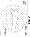
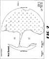
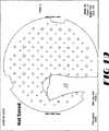
図1は、本発明によるシステムの1つの実施形態、及び、本発明による1つの設定例を示す概略図である。ここで、膝関節についての外科手術、この場合は、単一区画膝関節形成術を行うことができる。本発明によるシステム及び方法は、上述の種類又はその他の種類の基準器が、物理的に、実際に又はその他の手段で、移植され、取り付けられ又はその他の方法で関連付けられることができる種々の身体部分、例えば、脛骨10及び大腿骨12を追跡することができる。図1に示される実施形態では、基準器14は、構造フレームである。その一部は、反射素子を備え、その一部は、LED能動素子を備え、その一部は、両方を備え、少なくとも一緒に動作して、基準器14、及び、それが取り付けられるか、その他の方法で関連付けられる10及び12のような部品の位置及び方向に関連する(「を追跡する」)データを、感知、格納、処理及び/又は出力するのに適した立体赤外線センサを用いて追跡することができる。上述のように、位置センサ16は、基準器14及び関連付けられる部材の位置及び方向を、所望の電気的、磁気的、電磁気的、音響的、物理的、高周波又はその他の能動的又は受動的技術により感知するためのいかなる種類のセンサ機能であってもよい。好ましい実施形態では、位置センサ16は、多少の差はあれ、メートルのオーダーで、離れて配置される一組の赤外線センサである。その出力は、基準器14に関する位置及び方向情報を提供するために一緒に処理される。 FIG. 1 is a schematic diagram illustrating one embodiment of a system according to the present invention and one example configuration according to the present invention. Here, a surgical operation on the knee joint, in this case a single compartment knee arthroplasty, can be performed. The system and method according to the present invention provides a variety of bodies in which the above or other types of fiducials can be implanted, attached or otherwise associated, physically, actually or by other means. Portions such as the
図1で示される実施形態では、計算機能18は、処理機能、記憶機能、入力/出力機能を備えることができ、独立駆動形であっても、分散ベーシス形であってもよいが、所望の標準、アーキテクチャ、インターフェース、及び/又は、ネットワークトポロジー(network topology)によるものである。この実施形態では、計算機能18は、モニタに繋がれ、モニタ上には、グラフィック及びデータベースが外科手術の間に外科医に示される。画面は、好ましくは、触知形インターフェースを有し、外科医は、所望により、従来のキーボード及びマウスのインターフェースに加えて、又は、これらの代わりに、画面を指差し、クリックして、触知形画面へ入力することができる。さらに、特に、ある種の部品が適切に方向付けされ又は整合されるときに、他のものに対する位置/方向情報を収集するために、フットペダル20、又は、その他の便利なインターフェースが、機能18に結合され、その他の無線、又は、有線インターフェースが、外科医、看護士又はその他の所望のユーザーに、機能18を制御及び管理させるようにすることができる。試行部品、器具部品のような部材22は、基準器14を用いて、身体部分10及び12に対する位置と方向で追跡される。 In the embodiment shown in FIG. 1, the
計算機能18は、種々の形態のデータを処理、格納すると共に、モニタ24上に及びその他の方法で出力することができ、このデータは、全体又は一部が、身体部分10及び12、及び、部材22用の他の部品に対応する。例えば、図1に示される実施形態では、身体部分10及び12は、断面図で示されるか、少なくとも、種々の内部の状況、例えば、骨管及び表面構造がX線透視画像を用いて示される。これらの画像は、基準器14に取り付けられたCアームを用いて取得される。身体部分、例えば、脛骨10及び大腿骨12にも、基準器が取り付けられる。X線透視画像が基準器14を有するCアームを用いて取得されるとき、位置/方向センサ16は、脛骨10及び大腿骨12の位置及び方向に加えてX線透視ヘッドの位置も「見て」、追跡する。コンピュータは、この位置/方向情報とともにX線透視画像を格納し、X線透視画像の位置及び方向を、関連する身体部分に対して相関させる。従って、脛骨10及び対応する基準器14が動くとき、コンピュータは、自動的に、そして、これに相応して、空間における脛骨10の新たな位置を感知し、これに相応してモニタ24上で、道具、器具、参照体、試行品及び/又はインプラントを脛骨10の画像に対して動かすことができる。同様に、外科医又はその他の者の好みに合い、所望の画像化を実行するように、身体部分の画像が動かされ、また、身体部分及びこのような部材の両方が動かされ、また、画面上の画像が与えられる。同様に、追跡されている部材22、例えば、髄外ロッド、髄内ロッド、又は、その他の種類のロッド、が移動するとき、その画像は、モニタ24上を移動する。従って、モニタは、大腿骨12に対するモニタ24上の適切な位置及び方向に部材22を示す。従って、ロッド22は、あたかも外科医が適切にロッド22を誘導及び配置するために体の中をのぞくことができるかのように、大腿骨12の機械軸及びその他の特徴に対して適切な又は適切でない整合でモニタ24上に現れる。 The
コンピュータ機能18は、部材22、例えば、道具、器具、試行部品、インプラント部品、及び、外科手術で使用されるその他の部材、の構成、サイズ、及び、その他の特性に関連するデータを記憶することもできる。これらが、位置/方向センサ16の感知領域に導入されるとき、計算機能18は、誘導、配置、評価及びその他の用途のための道具、器具、試行部品、インプラント部品及びその他の部材22のコンピュータ生成画像を生成し、身体部分10及び12のX線透視画像に重ねて、又は、これらと組み合わせて表示する。 The
さらに、コンピュータ機能18は、例えば、指定用器具すなわちプローブ26を用いて位置/方向センサ16の感知領域中のいかなる点も追跡することができる。プローブは、基準器14を備えることも、基準器14に取り付けられることもできる。外科医、看護士又はその他のユーザーは、プローブ26の先を骨構造上の標識点のような点に当ててフットペダル20を動作させるか、又は、その他の手段で標識点位置に気付くようにコンピュータ18に指示する。位置/方向センサ16は、基準器14の位置及び方向を「見て」、プローブ26の先が基準器14に対してどこにあるのかを「知り」、フットペダル20が押されるか、その他の指令が与えられると、その点又はプローブ26により指定された他の位置を、計算して記憶すると共に、所望の時に、所望の形態、方法又は色でモニタ24上に表示することができる。このように、プローブ26は、骨構造上の標識点を指定するのに使用され、コンピュータ18が、骨基準器14の動きに対して、仮想又は論理的な情報、例えば、大腿骨12、脛骨10及びその他の身体部分の機械軸28、内外軸30及び前/後軸32を、他の仮想、又は、実際の構成体又は参照体に加えて、記憶又は追跡することを可能にする。 Further, the
図2−36の主題のような本発明の1つの実施形態によるシステム及び方法は、Medtronic Sofamor Danek Technologiesによって提供される、いわゆる、FluoroNAVシステム及びソフトウェアを用いることができる。このようなシステム又はその特徴は、米国特許第5,383,454号;5,871,445号;6,146,390号;6,165,81号;6,235,038号及び6,236,875号、及び関連(35U.S.C.セクション119及び/又は190の下における)特許において開示される。これらは全て、この参照によって、ここに取り込まれる。その他の望ましいシステムが、画像化、データ保存、身体部分及び部材の追跡、及びその他の目的のために、上述のように、使用される。 A system and method according to one embodiment of the invention, such as the subject of FIG. 2-36, can use the so-called FluoroNAV system and software provided by Medtronic Sofamor Danek Technologies. Such systems or features thereof are described in US Pat. Nos. 5,383,454; 5,871,445; 6,146,390; 6,165,81; 6,235,038 and 6,236. , 875, and related patents (under 35 U.SC section 119 and / or 190). All of which are hereby incorporated by this reference. Other desirable systems are used as described above for imaging, data storage, body part and member tracking, and other purposes.
FluoroNAVシステムは、4つ、場合によっては、5つの素子を有する、参照フレームタイプ基準器14の使用を必要とし、これらの素子は、基準器14、及び、身体部分、道具、器具、試行部品、インプラント部品、又は、追跡される他の装置又は構造の位置/方向のための赤外線センサによって追跡される。このようなシステムは、また、少なくとも1つのプローブ26を用いるが、外科医は、プローブを適正に配置して、例えばプローブの先の位置に気付くようにコンピュータに信号を送り、又は命令をすることによって、解剖学的組織上の点又はその他の場所を選択し、指定し、登録し、又は、その他の手段でシステムに知らせるために、そのプローブを用いることができる。FluoroNAVシステムは、また、基準器が取り付けられている身体部分のX線透視画像を取得するために用いられるCアームの位置及び方向も追跡し、センサ16によって追跡された位置/方向情報に適合するX線透視画像の撮像と記録を行う。従って、モニタ24は、仮想構成体及び参照体のコンピュータ生成画像と組み合わされた骨のX線透視画像を、道具、器具、試行部品、インプラント部品、及び、誘導、骨の切除、評価及びその他の目的のために外科手術と関連して用いられるその他の部材とともに表わすことができる。 The FluoroNAV system requires the use of a reference frame type fiducial 14, which has four, and possibly five, elements that include the fiducial 14, and body parts, tools, instruments, trial parts, Tracked by infrared sensor for position / orientation of implant component or other device or structure being tracked. Such a system also uses at least one
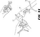
図2−39は、上で言及されたFluoroNAVシステムで実行されている本発明のある特定の実施形態及び変形による単一区画膝関節形成外科手術方法と関連する種々の図である。図2は、外科手術分野での人間の膝関節及び対応する大腿骨及び脛骨を示し、大腿骨及び脛骨には、本発明のこの実施形態に従って基準器14が堅く取り付けられている。基準器14の取り付けは、好ましくは、外科手術用のこぎりの振動、及び、外科手術中に起こるその他の現象に持ちこたえ、システムによって追跡される身体部分に対する基準器14の実質的な動きを可能としない構造を用いて実施される。 FIGS. 2-39 are various views associated with certain embodiments of the present invention and single-compartmental knee arthroplasty methods performed with the FluoroNAV system referred to above. FIG. 2 shows a human knee joint and corresponding femur and tibia in the surgical field, to which the fiducial 14 is rigidly attached according to this embodiment of the present invention. Attachment of the fiducial 14 preferably resists vibrations of the surgical saw and other phenomena that occur during the surgical procedure and does not allow substantial movement of the fiducial 14 relative to the body part being tracked by the system. Implemented using the structure.
図3は、基準器14が取り付けられた身体部分のX線透視画像が取得されているところを示す。この実施形態でのX線透視用ヘッド上の基準器14は、センサ16によって追跡するためのLEDすなわち「能動」エミッタを備える円柱の形をしたケージ(cage)である。脛骨10及び大腿骨12に取り付けられた基準器14をも見ることができる。大腿骨12に取り付けられた基準器14は、反射性の球の代わりにLEDを用い、従って能動であり、画像の下部に延びているのが見られるワイヤによってパワーが与えられる。 FIG. 3 shows that an X-ray fluoroscopic image of the body part to which the
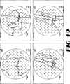
図4−10は、コンピュータ18によって受け取られ、その中に記録され、格納された位置及び/又は方向情報とともに取得され、モニタ24上に示されるX線透視画像である。図4は、身体部分の画像がないオープン領域であるが、球状のX線透視用の波面を用いて取得される画像を、モニタ24の実質的に平坦な面で、標準化するために用いられる光学印(optical indicia)を示す。図5は、大腿骨12ヘッドの画像を示す。この画像は、人工装具部品を最終的に配置する機械軸及び大腿骨に係わる他の関連構成体を設定する目的で、外科医が大腿骨頭の回転中心を指定することを可能にするために撮られる。このような回転中心は、寛骨臼又は人工装具内に大腿骨を関節で繋ぎ、多くの位置及び方向情報のサンプルを収集し、次に、コンピュータに平均的な回転中心を計算させることによって、設定される。回転中心は、プローブを用い、大腿骨頭上の多くの点を指定し、コンピュータに、幾何学的中心、又は、集められた点の幾何学様式(geometry)に対応する中心を計算させることによって設定される。さらに、モニタ上に表示されたグラフィック表示、例えば、制御可能に大きさが定められた円は、画面上の触知入力を用いて外科医によって平面画像上の大腿骨頭の形状に合わせられ、そのグラフィックによって中心を、例えば、円の軸の交点としてコンピュータによって表示されるように指定する。空間内の点又は構成体を決定、計算又は設定するためのその他の技術は、骨構造に対応していても、していなくても、本発明に従って用いられる。 FIGS. 4-10 are fluoroscopic images received by the
図5は、大腿骨頭のX線透視画像を示す。一方、図6は、標識点を指定し、機械軸又はその他の回転軸のような軸又は構成体を設定するのに使用されることができる、膝関節の前/後面図を示す。図7は、脛骨の遠位端を示す。図8は、膝関節の側面図を示す。図9は、膝関節の別の側面図を示す。一方、図10は、脛骨の遠位端の側面図を示す。 FIG. 5 shows a fluoroscopic image of the femoral head. On the other hand, FIG. 6 shows an anterior / posterior view of the knee joint that can be used to designate landmarks and set axes or components such as machine axes or other rotational axes. FIG. 7 shows the distal end of the tibia. FIG. 8 shows a side view of the knee joint. FIG. 9 shows another side view of the knee joint. On the other hand, FIG. 10 shows a side view of the distal end of the tibia.
外科手術に関連する部材の登録
図11−14は、外科手術で使用される部材22の指定又は登録を示す。登録とは、単純に、それがどのように達成されようとも、どの身体部分、部材又は構成体がどの基準器に対応するか、そして、身体部分、部材又は構成体の位置及び方向が、その対応する基準器又は次に部材に取り付けられる衝撃装置又はその他の部品に取り付けられた基準器の位置及び方向にどのように関連するかをコンピュータが知ることを保証することを意味する。このような登録又は指定は、図4−10に関して論じられたように骨すなわち身体部分を登録する前又は後になされる。図11は、基準器14が取り付けられた部材22、例えば、器具部品を、技術者がプローブ26を用いて指定しているところを示す。センサ16は、部材22に取り付けられた基準器14の位置及び方向、及び、先端が部材22上の標識点に触れられているプローブ26に取り付けられた基準器14の位置及び方向を「見る」。技術者は、画面上で又はその他の手段で、部材の識別子(identification)を指定する。フットペダルを作動させるか、その他の方法で、コンピュータにこのような識別子、例えば、特定の膝関節インプラント製品のための特定の切断ブロック部品を表示するために必要とされるデータに対応したデータを、部品22に取り付けられた特定の形状をした基準器14と相関させるように指示する。コンピュータは、次に、部材22用のデータ、例えば、構成及び形状データと相関する部品22用の基準器に関連する識別子、位置及び方向情報を格納した。そして、登録の際に、センサ16が、赤外線領域で部材22の基準器14を追跡するとき、モニタ24は、切断ブロック部品22が、移動及び回転しているところ、及び、同じく追跡されている身体部分に対して適切に配置され、方向付けされているところを示すことができる。図12−14は、その他の器具部品22のための同様の登録を示す。Registration of Members Relevant to Surgery FIGS. 11-14 illustrate the designation or registration of
解剖学的組織及び構成体の登録
同様に、身体部分10及び12の機械軸及びその他の軸又は構成体も、システムによる追跡のために「登録」されることができる。再度、システムは、図4−10で示された種類の大腿骨頭、膝関節、足関節の画像を取得するためにX線透視鏡を用いた。システムは、画像獲得の前に身体部分上に配置され、外科手術処置の間に同じ位置にとどまる基準器14を用いて、上で論じられたように、リアルタイムに、このような画像をCアーム、及び、患者の解剖学的組織の位置及び方向と相関させる。これらの画像及び/又はプローブを用いて、外科医は、直交する図、通常は、前/後面及び側面図において大腿骨頭及び足関節の中心を、タッチ画面上で選択し、コンピュータ18に登録することができる。外科医は、足関節上のように、膝関節又は皮膚上の手術部位、又は皮膚の外科手術的立体裁断において、所望の解剖学的組織の標識点を選択するためにプローブを用いる。これらの点は、システムによって三次元空間で登録され、患者の解剖学的組織上の、好ましくは手術中に配置される基準器に対して追跡される。図15は、外科医が、コンピュータ18に上顆軸を決定、格納又は表示するために必要とされる1つの点の位置を与えて、プローブ26を用いて大腿骨12の顆部上の標識点を指定又は登録するためにプローブ26を用いているところを示す(前−後面及び側面での上顆軸を示す図20を参照のこと)。図15のように実際の骨構造を用いて各点を登録することは、軸を設定するための1つの好ましい方法であるけれども、プローブ26が骨構造の面上の複数の点を指定するのに使用される、クラウドオブポイントアプローチ(a cloud of points approach)が用いられる。上で述べられたように回転中心を設定するために身体部分を動かし、動きを追跡することもできる。大腿骨頭及び顆部品のための回転中心が一旦登録されると、コンピュータは、大腿骨12の機械軸用のデータの計算、格納、描写などを行うことができる。図17は、再度、プローブ26が、大腿骨12の顆部品上の点を指定するために使用されているところを示す。Registering Anatomical Structures and Structures Similarly, the machine axes and other axes or structures of
図18は、外科医が大腿骨の機械軸を設定するためにプローブ26を用いて骨表面上のある点を登録するときに、画面上の画像が取得されているところを示す。脛骨の機械軸は、次に、脛骨の近位及び遠位端の中心を決定するための点を指定することによって設定される。従って、機械軸は、コンピュータ18によって、計算、格納され、それに続いて、使用される。図20は、前/後面及び側面の両方において上顆軸を決定するための指定点を示す。一方、図21は、前−後軸の決定を示し、それは、画面上に表わされる。後顆軸も、点を指定することによって、又は、その他の所望の手段によって決定され、コンピュータ生成幾何学的画像上に重ねられて表わされるか、X線透視画像と組み合わせて表示される。その全ては、センサ16によって追跡されている基準器14に適合する。 FIG. 18 shows the on-screen image being acquired when the surgeon registers a point on the bone surface using the
図23は、調節可能な円グラフィックを示し、円グラフィックは、大腿骨頭の直交するX線透視画像と組み合わされて生成及び表示されることができる。また、円グラフィックは、外科医が、前−後面及び側面の両方で大腿骨頭の中心を設定するために画面上でX線透視画像を動かすとき、コンピュータ18によって追跡される。 FIG. 23 shows an adjustable circle graphic, which can be generated and displayed in combination with an orthogonal fluoroscopic image of the femoral head. The circular graphic is also tracked by the
図24は、上で述べられたように指定された点から前−後軸、上顆軸及び後顆軸を示す画面上画像である。これらの構成体は、コンピュータ18によって生成され、大腿骨12のX線透視画像と組み合わされてモニタ24上に示され、X線透視画像に対して正しく配置され、方向付けされ、システムによって追跡される。図24の左下で示されたX線透視/コンピュータ生成画像の組み合わせにおいて、放射線に不透明な材料を含む、前記のある図に示された「のこぎり骨」膝関節は、X線透視法で表わされ、センサ16を用いて追跡される。一方、コンピュータはほぼ水平に走る大腿骨12の機械軸を生成し、表示する。上顆軸は、ほぼ垂直に走る。前/後軸は、ほぼ対角線上に走る。右下の画像は、側面図において同様の情報を示す。ここで、前−後軸は、ほぼ水平である。一方、上顆軸は、ほぼ対角線上に走る。機械軸は、ほぼ垂直に走る。 FIG. 24 is an on-screen image showing the anterior-posterior axis, epicondylar axis and posterior condylar axis from the points specified as described above. These constructs are generated by the
図24は、外科手術中の誘導、配置及び評価に役立つ、関連する軸及び構成体を生成するために、図4−39のシステムにより生成及び表示された多くの画面表示と同様に、中央に、登録される標識点のリストを示す。標識点を登録し、関連する軸を設定するプロセスにおいて、外科医に次のステップを提案するテキスト形式の(textural)手掛かりも示されることができる。このような指示は、コンピュータ18が、部材22及び骨の場所の登録、及び、外科手術の間に外科医によって採られるその他の手段を1つのステップから次のステップへ追跡するとき、生成されてもよい。 FIG. 24 is centered, as are many screen displays generated and displayed by the system of FIGS. 4-39 to generate related axes and structures that are useful for navigation, placement and evaluation during surgery. Shows a list of registered mark points. Textural cues that suggest the next step to the surgeon in the process of registering landmarks and setting the associated axes can also be shown. Such instructions may be generated when the
図25は、外科医により登録された点による脛骨の機械、横、前−後軸を示す。 FIG. 25 shows the mechanical, lateral, anterior-posterior axis of the tibia with points registered by the surgeon.
図26は、大腿骨12の軸を示す別の画面上画像である。 FIG. 26 is another on-screen image showing the axis of the
所望の軸又はその他の構成体は、UKAに関連するいずれかの目的ために、膝関節の所望の静的又は運動学的な機能を示す画像及びデータをモデル化及び生成するために、生成、追跡及び表示される。 Desired axes or other constructs are generated to model and generate images and data showing the desired static or kinematic function of the knee joint for any purpose related to UKA, Tracked and displayed.
骨の整形
大腿骨及び脛骨に関連する機械軸及びその他の回転軸及び構成体が設定された後、器具は、図4−39に示された本発明の実施形態により試行部品及びインプラント部品に適切に適合するように骨を切断又は整形するために、適切に方向付けされる。基準器14が搭載された器具、例えば、切断ブロックが用いられる。次に、システムは、外科医が最適な配置を行うために器具を操るとき、それを追跡することができる。言い換えると、外科医は、システム及びモニタを用いて最適配置を行うためにその器具を「誘導」することができる。このようにして、器具は、この実施形態のシステムにより、管を侵さない髄外ロッド上、髄内ロッド上又はその他のタイプのロッド上の機械及び回転軸又は参照軸に骨の切除を揃えるように、配置されることができる。タッチ画面24は、特に、インプラントのサイズ及びおそらくインプラントのタイプを適切に選択するために、切断ブロックのような器具及び/又はこのプロセスの間に器具及びロッドに関連するインプラントを表示することもできる。器具が動くとき、部品の相対的な位置の内反/外反、屈曲/伸展、及び、内側/外側回転が、参照軸に対して計算され、示される。好ましい実施形態では、これは、毎秒6サイクル、又は、それ以上の速度で、行われる。次に、器具位置は、コンピュータ内で、及び、物理的に固定され、骨の切除が行われる。After the mechanical and other rotational axes and components associated with the femur and tibia are set, the instrument is suitable for trial and implant parts according to the embodiment of the invention shown in FIG. 4-39. Appropriately oriented to cut or shape the bone to fit. An instrument on which the
図27は、衝撃装置22を介して基準器14が取り付けられた髄外ロッドの方向を示す。外科医は、大腿骨12のX線透視画像に重ねられた、又は、それと組み合わされた、ロッドについての、図29で示されるような画像を有する画面24を見る。これは、その2つが、実際に、空間でお互いに関連して配置され、方向付けされるからである。次に、外科医は、好ましくは、大腿骨の機械軸に沿って、適切な場所にロッドを誘導し、それを適切な木槌又はその他の装置で深く打ち込む。大腿骨の骨幹端に穴を開け、リーマ、又は、その他のロッドを髄質の管の中に設置することは、脂肪塞栓症、出血、感染、及び、その他の不都合な、そして、望まれていない効果を引き起こすことがあるので、本発明はその必要を避ける。 FIG. 27 shows the direction of the extramedullary rod with the fiducial 14 attached via the
図28も、髄外ロッドが配置されているところを示す。図29は、前−後面及び側面の両方で、大腿骨及び脛骨のX線透視画像に重ねられた、又は、これと組み合わされた、軸、及び、ロッドのコンピュータ生成及び追跡画像を有するX線透視画像を示す。図30は、図29に示されるものに似た大腿骨のX線透視画像に重ねられたロッドを示す。 FIG. 28 also shows where the extramedullary rod is located. FIG. 29 shows X-rays with computer-generated and tracked images of axes and rods, superimposed or combined with fluoroscopic images of the femur and tibia, both anterior-posterior and lateral A perspective image is shown. FIG. 30 shows a rod superimposed on a fluoroscopic image of a femur similar to that shown in FIG.
図29は、大腿骨の画像に重ねられた部品の名前、左下に提案又は指示、そして、軸に対する内反/外反及び伸展におけるロッドの角度のような外科医に関連するその他の情報も示す。この情報のいずれか、又は、全ては、大腿骨に対して、ロッドを誘導及び配置するために用いられる。ロッドの配置の間又は後において、以下に論じられるように、追跡は、衝撃装置の基準器14から大腿骨の基準器14へと「引き継が」れる。 FIG. 29 also shows the name of the part superimposed on the image of the femur, suggestions or instructions in the lower left, and other information relevant to the surgeon such as varus / valgus with respect to the axis and rod angle in extension. Any or all of this information is used to guide and position the rod relative to the femur. During or after placement of the rod, tracking is “taken over” from the impactor fiducial 14 to the femoral fiducial 14, as discussed below.
一旦、髄外ロッド、髄内ロッド又はその他のタイプのロッドが配置されると、センサ16によって位置及び方向が追跡され、画面24に表示されて、器具が配置される。このように、基準器14が取り付けられて、顆の前部の切断を設定するのに使用される種類の切断ブロックは、その領域に導入され、ロッド上に配置される。切断ブロックは、特定のインプラント製品に対応し、その製品の特定のインプラントサイズに対応するように、画面上で調節及び指定されるので、コンピュータ18は、X線透視画像に重ねられる切断ブロック及び大腿骨部品のグラフィックを生成及び表示することができる。従って、外科医は、骨の上の切断ブロックの画像だけでなく、最終的に取り付けられる対応する大腿骨部品の画像も用いて、画面上で、切断ブロックの誘導及び配置を行うことができる。外科医は、このように、実際の切断ブロック部品の配置を調節することができ、画面上に示される最終的な大腿骨部品に最適に適合し、これを最適に配置するように大腿骨の顆部の前部を切断するために、切断ブロック部品をロッドに固定することができる。その他の切断ブロック及びその他の切除器が、顆部品上に同様に配置され、行われてもよい。 Once an extramedullary rod, intramedullary rod, or other type of rod is placed, the position and orientation is tracked by sensor 16 and displayed on
同様に、器具は、脛骨10の近位部で、センサ16によって追跡されて、切断ブロック及びインプラント部品の画像による画面上で、誘導及び配置されてもよい。 Similarly, the instrument may be tracked by the sensor 16 at the proximal portion of the
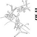
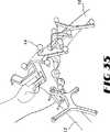
図33−37は、器具が、インプラント部品の特定のサイズを受け入れるために顆部品を切除するためのシステムによって追跡されて、大腿骨12に対して配置されているところを示す。種々の切断ブロック及びそれらが取り付けられた基準器は、これらの図で見ることができる。 FIGS. 33-37 show the instrument being tracked and placed against the
試行品及びインプラントの誘導、配置、評価
骨の切除及び整形が達成されると、次に、インプラント試行品が、画面24上に表示されて器具を誘導及び配置するのと同様の方法で、取り付けられ、システムによって追跡される。従って、大腿骨部品の試行品、脛骨プラトー(plateau)試行品、及び、軸受板試行品が、その試行品に対応したコンピュータ生成オーバーレイ(overlays)を用いて画面上に誘導されて、配置されてもよい。Guide, implant, and evaluation of trial and implant Once bone resection and shaping has been achieved, the implant trial is then installed in a manner similar to that displayed on
試行品の取り付けプロセスの間、及び、インプラント部品の取り付けプロセス、器具の配置プロセスの間、又は、本発明による外科手術又はその他の手術におけるその他の所望の時に、システムは、第1の基準器による部品の追跡から、第2の基準器による部品の追跡へと遷移、又は、移行することができる。従って、試行品の大腿骨部品は、基準器14が取り付けられた衝撃装置に取り付けられる。試行部品は、衝撃装置を用いて、取り付けられ、配置される。コンピュータ18は、衝撃装置上の基準器に対する試行品の位置及び方向を、例えば、衝撃装置に取り付けられた部品の以前の登録によって、「知っている」。従って、コンピュータ18は、顆部品のX線透視画像に重ねられた大腿骨試行部品の画像を画面24上に生成及び表示することができる。機械軸と揃うように、及び、その他の軸に対する適切な方向に従い、試行部品が大腿骨の顆部品上に適切に配置される前、間、後の所望の時に、システムは、衝撃装置に取り付けられたものよりもむしろ大腿骨に取り付けられた基準器を用いて試行部品の位置の追跡を始めるようにフットペダル又はその他の手段により指示される。好ましい実施形態によると、センサ16は、この時、衝撃装置及び大腿骨12の上の基準器の両方を「見る」。従って、それは、衝撃装置上の基準器に対する試行部品の位置及び方向をすでに「知っており」、従って、後の使用のため、大腿骨12の基準器に対する試行部品の位置及び方向を計算し、格納することができる。一旦、この「引き継ぎ」が起こると、衝撃装置は取り外され、試行部品は、大腿骨12の一部として、又は、大腿骨12と一緒に動いて、大腿骨の基準器14で追跡される。同様の引継ぎ手続きが本発明に従い、所望により、その他の例で用いられてもよい。 During the trial attachment process and during the implant part attachment process, the instrument placement process, or at any other desired time in a surgical procedure or other operation according to the present invention, the system is in accordance with the first fiducial. A transition from part tracking to part tracking by a second fiducial can be made. Therefore, the femoral component of the trial product is attached to the impact device to which the
また、脛骨試行品は、近位の脛骨に配置され、プローブ26を用いて登録される。プローブ26は、骨釘穴のような既知の座標の脛骨試行品についての、好ましくは、少なくとも3つの特徴を指定するために用いられる。プローブがそれぞれの特徴の上に位置するとき、システムは、その座標位置を格納するように指示される。従って、システムは、格納された座標に脛骨試行品の特徴の座標を一致させることができる。次に、システムは、脛骨解剖学的組織参照フレームに対して、脛骨試行品を追跡する。 Also, the tibial trial is placed in the proximal tibia and registered using the
一旦試行部品が取り付けられると、外科医は、その部品及び関節の整合性及び安定性を評価することができる。このような評価の間、試行整復において、コンピュータは、試行部品間の相対的な動きをモニタ24上に表示することができる。従って、外科医は,膝関節の運動を向上させるために、軟部組織を解放及び変化させることが可能となる。システムは、外科医が望むのであれば、どの軟部組織の解放を行うことができるかのような情報に基づく提案をするためにルール及び/又は情報を適用することもできる。そのシステムは、軟部組織の解放がどのように行われることができるかを表示することもできる。 Once the trial part is installed, the surgeon can assess the integrity and stability of the part and joint. During such evaluation, in trial reduction, the computer can display the relative movement between trial parts on the
この評価の間、外科医は、外側/内側回転又は回転ゆるみ試験、内反/外反試験、及び0度及び90度及び範囲の中央での前−後引き出しのような、ある種の評価プロセスを行ってもよい。従って、前後引き出し試験において、外科医は、脛骨を第1の場所に配置し、フットペダルを押すことができる。次に、彼は、第2の場所に脛骨を配置し、再度、フットペダルを押す。これにより、コンピュータは、関与する患者及び製品にとって受け入れ可能であろうともなかろうとも、引き出しを計算及び表示するため2つの場所を登録及び格納した。もし、受け入れ可能でないのであれば、コンピュータは、靭帯又はその他の組織を解放するための、又は、その他の部品のサイズ又はタイプを用いるための提案を生成及び表示するためにルールを適用することができる。一旦、適切な組織解放がなされ、必要ならば、整合性及び安定性が全ての軸について画面上に定量的に示されるように受け入れ可能であると、試行部品を取り外すことができ、試行部品が誘導され、取り付けられ、評価されるのと同様の方法で、実際の部品が誘導され、取り付けられ、性能において評価される。 During this evaluation, the surgeon performs some kind of evaluation process, such as an outside / inside rotation or rotation looseness test, a varus / valgus test, and an anterior-posterior withdrawal at 0 and 90 degrees and the middle of the range. You may go. Thus, in an anteroposterior drawer test, the surgeon can place the tibia in the first location and press the foot pedal. He then places the tibia in the second location and again presses the foot pedal. This allowed the computer to register and store two locations for calculating and displaying the drawer, whether acceptable or not for the patient and product involved. If unacceptable, the computer may apply rules to generate and display suggestions for releasing ligaments or other tissue or using other part sizes or types. it can. Once the appropriate tissue release has been made and if necessary, the trial part can be removed once the consistency and stability are acceptable as shown quantitatively on the screen for all axes, In a manner similar to being guided, mounted and evaluated, the actual part is guided, mounted and evaluated in performance.
事例の最後に、全ての整合情報は、患者ファイルに格納される。これは、インプラント配置の結果が、骨の切除がなされる前に見られることができるという事実のために、外科医にとって大きな助けとなる。システムは、膝蓋骨、切断ガイドの結果生じる配置及び膝蓋骨の試行品の位置を追跡することもできる。システムは、次に、膝蓋骨大腿骨溝を有する膝蓋骨の整合を追跡することができ、膝蓋骨の傾きのような問題についてフィードバックを与えるであろう。 At the end of the case, all matching information is stored in the patient file. This is of great help to the surgeon due to the fact that the result of the implant placement can be seen before a bone resection is made. The system can also track the patella, the resulting placement of the cutting guide and the position of the patella trial. The system can then track the alignment of the patella with the patella femoral groove and provide feedback on issues such as patella tilt.
本発明によるシステム及び方法によって提供される追跡及び画像情報は、遠隔治療技術を容易にする。それらは、遠い地理的位置に配られる有用な画像を提供するからである。この場合、熟達した外科手術又は医学の専門家が外科手術の間に協力することができる。従って、本発明によるシステム及び方法は、ネットワークにつながった、又は、その他の方法でその他の場所にある計算機能と、PSTN、パケット交換ネットワークのような情報交換インフラストラクチャ、又は、その他の望むものによって、通信している計算機能18と関連して用いられる。このような遠隔画像化は、コンピュータ、ワイヤレス装置、ビデオ会議装置、又は、本発明により生成された画像又はその一部を現在又は将来に表わすことができるその他のモード又はその他のプラットフォームで起きてもよい。交換又は非交換テレフォンコール接続のようなパラレルコミュニケーションリンクも、このような遠隔治療技術の一部に伴ってもよく、それを形成してもよい。インプラント供給業者、又は、人工装具購入者又は流通業者のオンラインカタログのような遠隔のデータベースは、リアルタイムに外科医に外科手術の間に調達及び使用されるインプラントのための追加のオプションへのアクセスを与えるために、機能18の一部を形成してもよく、機能18とネットワークで繋がってもよい。 The tracking and image information provided by the system and method according to the present invention facilitates teletherapy techniques. They provide useful images that are distributed at distant geographical locations. In this case, a skilled surgical or medical professional can cooperate during the surgical procedure. Thus, the system and method according to the present invention is based on computing functions connected to the network or otherwise located elsewhere, and information exchange infrastructure such as PSTN, packet switched networks, or others as desired. Used in conjunction with the
Claims (13)
Translated fromJapanese(b)基準器の位置を追跡するように構成された少なくとも1つの位置センサと、
(c)前記基準器及び膝関節の位置及び方向を追跡するために、少なくとも膝関節の部分の少なくとも1つの画像を格納し、前記少なくとも1つのセンサから情報を受け取るように構成されたコンピュータと、
(d)道具を用いて膝関節の部分を形成する骨に取り付けられるように構成された単一区画膝関節形成外科手術器具部品とを備え、道具が、基準器に取り付けられ、それによって、外科手術器具部品の位置が前記センサによって追跡可能となり、外科手術器具部品の位置及び方向が、前記コンピュータによって追跡可能となり、
(e)膝関節に対する外科手術器具の誘導及び配置のために、コンピュータから情報を受け取って、膝関節に対して配置されて方向付けされた外科手術器具部品の少なくとも1つの画像を表示するように構成されたモニタを備える、
膝関節の部分に単一区画膝関節形成外科手術を行うシステム。(A) a reference device including an imaging device for acquiring an image of at least a knee joint portion, wherein the imaging device and at least one bone forming the knee joint portion can be tracked by a position sensor, respectively. Attached to the
(B) at least one position sensor configured to track the position of the reference device;
(C) a computer configured to store at least one image of a portion of the knee joint and receive information from the at least one sensor to track the position and orientation of the fiducial and the knee joint;
(D) a single-compartment knee arthroplasty surgical instrument component configured to be attached to a bone forming a portion of a knee joint using a tool, wherein the tool is attached to a fiducial and thereby surgical The position of the surgical instrument part can be tracked by the sensor, the position and orientation of the surgical instrument part can be tracked by the computer,
(E) receiving information from the computer for guidance and placement of the surgical instrument relative to the knee joint to display at least one image of the surgical instrument component positioned and oriented relative to the knee joint; With a configured monitor,
A system that performs single-compartment knee arthroplasty on the knee joint.
(b)基準器の位置を追跡するように構成された少なくとも1つの位置センサと、
(c)前記基準器及び膝関節の位置及び方向を追跡するために、少なくとも膝関節の部分の少なくとも1つの画像を格納し、前記少なくとも1つのセンサから情報を受け取るように構成されたコンピュータと、
(d)道具を用いて膝関節の部分を形成する骨に取り付けられるように構成された単一区画膝関節形成術インプラント試行部品とを備え、道具が、基準器に取り付けられ、従って、試行部品の位置が、前記センサによって追跡可能となり、試行部品の位置及び方向が、前記コンピュータに追跡可能となり、
(e)コンピュータから情報を受け取り、膝関節に対する試行部品の誘導及び配置のために、膝関節に対して配置されるとともに方向付けされた試行部品の少なくとも1つの画像を表示するように構成されたモニタを備える、
膝関節の部分に単一区画膝関節形成外科手術を行うシステム。(A) an imaging device for acquiring an image of at least a portion of the knee joint, wherein the imaging device and the femur are each attached to a reference device that can be tracked by a position sensor;
(B) at least one position sensor configured to track the position of the reference device;
(C) a computer configured to store at least one image of a portion of the knee joint and receive information from the at least one sensor to track the position and orientation of the fiducial and the knee joint;
(D) a single-compartment knee arthroplasty implant trial component configured to be attached to the bone forming part of the knee joint using the tool, wherein the tool is attached to the fiducial and thus the trial part Can be tracked by the sensor, and the position and orientation of the trial part can be tracked by the computer,
(E) receiving information from the computer and configured to display at least one image of the trial component placed and oriented relative to the knee joint for guidance and placement of the trial component relative to the knee joint Equipped with a monitor,
A system that performs single-compartment knee arthroplasty on the knee joint.
(b)基準器の位置を追跡するように構成された少なくとも1つの位置センサと、
(c)前記基準器及び膝関節の位置及び方向を追跡するために、少なくとも膝関節の部分の少なくとも1つの画像を格納し、前記少なくとも1つのセンサから情報を受け取るように構成されたコンピュータと、
(d)道具を用いて膝関節の部分を形成する骨に取り付けられるように構成された単一区画膝関節形成術インプラント部品とを備え、道具が、基準器に取り付けられ、それによって、インプラント部品の位置が、前記センサによって追跡可能となり、インプラント部品の位置及び方向が、前記コンピュータに追跡可能となり、
(e)膝関節に対するインプラント部品の誘導及び配置のために、膝関節に対して配置されるとともに方向付けされたインプラント部品の少なくとも1つの画像を表示するためにコンピュータから情報を受け取るように構成されたモニタを備える、
膝関節の部分に単一区画膝関節形成外科手術を行うシステム。(A) an imaging device for acquiring an image of at least a portion of the knee joint, wherein the imaging device and the femur are each attached to a reference device that can be tracked by a position sensor;
(B) at least one position sensor configured to track the position of the reference device;
(C) a computer configured to store at least one image of a portion of the knee joint and receive information from the at least one sensor to track the position and orientation of the fiducial and the knee joint;
(D) a single-compartment knee arthroplasty implant component configured to be attached to the bone forming part of the knee joint using the tool, the tool being attached to the fiducial, thereby providing the implant part The position of the implant part can be tracked by the sensor, and the position and orientation of the implant part can be tracked by the computer,
(E) configured to receive information from a computer for displaying at least one image of the implant component positioned and oriented relative to the knee joint for guidance and placement of the implant component relative to the knee joint; Equipped with a monitor,
A system that performs single-compartment knee arthroplasty on the knee joint.
Applications Claiming Priority (3)
| Application Number | Priority Date | Filing Date | Title |
|---|---|---|---|
| US27181801P | 2001-02-27 | 2001-02-27 | |
| US35589902P | 2002-02-11 | 2002-02-11 | |
| PCT/US2002/005956WO2002067784A2 (en) | 2001-02-27 | 2002-02-27 | Surgical navigation systems and processes for unicompartmental knee |
Publications (3)
| Publication Number | Publication Date |
|---|---|
| JP2004523297A JP2004523297A (en) | 2004-08-05 |
| JP2004523297A5 JP2004523297A5 (en) | 2005-12-22 |
| JP4113779B2true JP4113779B2 (en) | 2008-07-09 |
Family
ID=26955127
Family Applications (2)
| Application Number | Title | Priority Date | Filing Date |
|---|---|---|---|
| JP2002567159AExpired - Fee RelatedJP4113779B2 (en) | 2001-02-27 | 2002-02-27 | Single-compartment knee joint surgical guidance system and method |
| JP2002567158AExpired - Fee RelatedJP4219170B2 (en) | 2001-02-27 | 2002-02-27 | Knee joint replacement system and method |
Family Applications After (1)
| Application Number | Title | Priority Date | Filing Date |
|---|---|---|---|
| JP2002567158AExpired - Fee RelatedJP4219170B2 (en) | 2001-02-27 | 2002-02-27 | Knee joint replacement system and method |
Country Status (9)
| Country | Link |
|---|---|
| US (11) | US6923817B2 (en) |
| EP (3) | EP1372516B1 (en) |
| JP (2) | JP4113779B2 (en) |
| KR (1) | KR20030082942A (en) |
| AT (2) | ATE431110T1 (en) |
| AU (2) | AU2002254047B2 (en) |
| CA (1) | CA2439249C (en) |
| DE (2) | DE60232315D1 (en) |
| WO (3) | WO2002067784A2 (en) |
Families Citing this family (570)
| Publication number | Priority date | Publication date | Assignee | Title |
|---|---|---|---|---|
| US8603095B2 (en) | 1994-09-02 | 2013-12-10 | Puget Bio Ventures LLC | Apparatuses for femoral and tibial resection |
| US6695848B2 (en) | 1994-09-02 | 2004-02-24 | Hudson Surgical Design, Inc. | Methods for femoral and tibial resection |
| US8480754B2 (en) | 2001-05-25 | 2013-07-09 | Conformis, Inc. | Patient-adapted and improved articular implants, designs and related guide tools |
| US8545569B2 (en) | 2001-05-25 | 2013-10-01 | Conformis, Inc. | Patient selectable knee arthroplasty devices |
| US8556983B2 (en) | 2001-05-25 | 2013-10-15 | Conformis, Inc. | Patient-adapted and improved orthopedic implants, designs and related tools |
| US9603711B2 (en) | 2001-05-25 | 2017-03-28 | Conformis, Inc. | Patient-adapted and improved articular implants, designs and related guide tools |
| US20030055502A1 (en)* | 2001-05-25 | 2003-03-20 | Philipp Lang | Methods and compositions for articular resurfacing |
| DE29704393U1 (en)* | 1997-03-11 | 1997-07-17 | Aesculap Ag, 78532 Tuttlingen | Device for preoperative determination of the position data of endoprosthesis parts |
| US6045551A (en) | 1998-02-06 | 2000-04-04 | Bonutti; Peter M. | Bone suture |
| US6477400B1 (en) | 1998-08-20 | 2002-11-05 | Sofamor Danek Holdings, Inc. | Fluoroscopic image guided orthopaedic surgery system with intraoperative registration |
| US6368343B1 (en) | 2000-03-13 | 2002-04-09 | Peter M. Bonutti | Method of using ultrasonic vibration to secure body tissue |
| US6447516B1 (en) | 1999-08-09 | 2002-09-10 | Peter M. Bonutti | Method of securing tissue |
| US9208558B2 (en) | 1999-08-11 | 2015-12-08 | Osteoplastics Llc | Methods and systems for producing an implant |
| US8781557B2 (en) | 1999-08-11 | 2014-07-15 | Osteoplastics, Llc | Producing a three dimensional model of an implant |
| AU6634800A (en) | 1999-08-11 | 2001-03-05 | Case Western Reserve University | Method and apparatus for producing an implant |
| US6702821B2 (en) | 2000-01-14 | 2004-03-09 | The Bonutti 2003 Trust A | Instrumentation for minimally invasive joint replacement and methods for using same |
| US7635390B1 (en) | 2000-01-14 | 2009-12-22 | Marctec, Llc | Joint replacement component having a modular articulating surface |
| US6635073B2 (en) | 2000-05-03 | 2003-10-21 | Peter M. Bonutti | Method of securing body tissue |
| US7104996B2 (en) | 2000-01-14 | 2006-09-12 | Marctec. Llc | Method of performing surgery |
| US6725080B2 (en) | 2000-03-01 | 2004-04-20 | Surgical Navigation Technologies, Inc. | Multiple cannula image guided tool for image guided procedures |
| US7547307B2 (en) | 2001-02-27 | 2009-06-16 | Smith & Nephew, Inc. | Computer assisted knee arthroplasty instrumentation, systems, and processes |
| US20050113846A1 (en)* | 2001-02-27 | 2005-05-26 | Carson Christopher P. | Surgical navigation systems and processes for unicompartmental knee arthroplasty |
| US7909831B2 (en)* | 2001-02-28 | 2011-03-22 | Howmedica Osteonics Corp. | Systems used in performing femoral and tibial resection in knee surgery |
| US8062377B2 (en) | 2001-03-05 | 2011-11-22 | Hudson Surgical Design, Inc. | Methods and apparatus for knee arthroplasty |
| US20020194023A1 (en)* | 2001-06-14 | 2002-12-19 | Turley Troy A. | Online fracture management system and associated method |
| US7708741B1 (en) | 2001-08-28 | 2010-05-04 | Marctec, Llc | Method of preparing bones for knee replacement surgery |
| US6719765B2 (en) | 2001-12-03 | 2004-04-13 | Bonutti 2003 Trust-A | Magnetic suturing system and method |
| JP3905393B2 (en)* | 2002-02-07 | 2007-04-18 | オリンパス株式会社 | Surgical device |
| JP2005516724A (en) | 2002-02-11 | 2005-06-09 | スミス アンド ネフュー インコーポレーテッド | Image guided fracture reduction |
| US9155544B2 (en) | 2002-03-20 | 2015-10-13 | P Tech, Llc | Robotic systems and methods |
| ES2241915T3 (en)* | 2002-03-21 | 2005-11-01 | Brainlab Ag | NAVIGATION DEVICE FOR A RETRACTOR. |
| US8180429B2 (en)* | 2002-04-17 | 2012-05-15 | Warsaw Orthopedic, Inc. | Instrumentation and method for mounting a surgical navigation reference device to a patient |
| US6980849B2 (en)* | 2002-04-17 | 2005-12-27 | Ricardo Sasso | Instrumentation and method for performing image-guided spinal surgery using an anterior surgical approach |
| US6993374B2 (en)* | 2002-04-17 | 2006-01-31 | Ricardo Sasso | Instrumentation and method for mounting a surgical navigation reference device to a patient |
| US8801720B2 (en) | 2002-05-15 | 2014-08-12 | Otismed Corporation | Total joint arthroplasty system |
| US7248914B2 (en) | 2002-06-28 | 2007-07-24 | Stereotaxis, Inc. | Method of navigating medical devices in the presence of radiopaque material |
| US6824539B2 (en)* | 2002-08-02 | 2004-11-30 | Storz Endoskop Produktions Gmbh | Touchscreen controlling medical equipment from multiple manufacturers |
| US7282052B2 (en)* | 2002-09-17 | 2007-10-16 | Ebi, L.P. | Unilateral fixator |
| US20040068263A1 (en)* | 2002-10-04 | 2004-04-08 | Benoit Chouinard | CAS bone reference with articulated support |
| JP2006509609A (en) | 2002-10-04 | 2006-03-23 | オルトソフト インコーポレイテッド | Computer-aided hip replacement surgery |
| US7869861B2 (en)* | 2002-10-25 | 2011-01-11 | Howmedica Leibinger Inc. | Flexible tracking article and method of using the same |
| JP2006504477A (en)* | 2002-11-05 | 2006-02-09 | アエスクラップ アクチェンゲゼルシャフト ウント コンパニー コマンディトゲゼルシャフト | Method and apparatus for determining the position of a prosthesis in the knee joint |
| AU2003297280B2 (en)* | 2002-11-14 | 2010-04-08 | Extraortho, Inc | Method for using a fixator device |
| AU2003287720A1 (en)* | 2002-11-14 | 2004-06-15 | General Electric Medical Systems Global Technology Company, Llc | Interchangeable localizing devices for use with tracking systems |
| US7318827B2 (en)* | 2002-12-02 | 2008-01-15 | Aesculap Ag & Co. Kg | Osteotomy procedure |
| ES2465090T3 (en) | 2002-12-20 | 2014-06-05 | Smith & Nephew, Inc. | High performance knee prostheses |
| US7542791B2 (en) | 2003-01-30 | 2009-06-02 | Medtronic Navigation, Inc. | Method and apparatus for preplanning a surgical procedure |
| US7660623B2 (en) | 2003-01-30 | 2010-02-09 | Medtronic Navigation, Inc. | Six degree of freedom alignment display for medical procedures |
| US6988009B2 (en)* | 2003-02-04 | 2006-01-17 | Zimmer Technology, Inc. | Implant registration device for surgical navigation system |
| WO2004070577A2 (en)* | 2003-02-04 | 2004-08-19 | Z-Kat, Inc. | Interactive computer-assisted surgery system and method |
| US7492930B2 (en)* | 2003-02-04 | 2009-02-17 | Aesculap Ag | Method and apparatus for capturing information associated with a surgical procedure performed using a localization device |
| WO2004070573A2 (en)* | 2003-02-04 | 2004-08-19 | Z-Kat, Inc. | Computer-assisted external fixation apparatus and method |
| EP1615577A2 (en)* | 2003-02-04 | 2006-01-18 | Orthosoft, Inc. | Cas modular bone reference assembly and limb position measurement system |
| WO2004070580A2 (en)* | 2003-02-04 | 2004-08-19 | Z-Kat, Inc. | Computer-assisted knee replacement apparatus and method |
| US20050021037A1 (en)* | 2003-05-29 | 2005-01-27 | Mccombs Daniel L. | Image-guided navigated precision reamers |
| ATE429185T1 (en) | 2003-06-02 | 2009-05-15 | Stephen B Murphy | METHOD FOR DETERMINING A COORDINATE SYSTEM FOR HIP ARTHROPLASTY |
| WO2004112610A2 (en) | 2003-06-09 | 2004-12-29 | Vitruvian Orthopaedics, Llc | Surgical orientation device and method |
| US7559931B2 (en)* | 2003-06-09 | 2009-07-14 | OrthAlign, Inc. | Surgical orientation system and method |
| AU2003246613A1 (en)* | 2003-06-27 | 2005-01-13 | Aesculap Ag And Co. Kg | Method and device for orienting a machining tool |
| US7158754B2 (en)* | 2003-07-01 | 2007-01-02 | Ge Medical Systems Global Technology Company, Llc | Electromagnetic tracking system and method using a single-coil transmitter |
| US20050020909A1 (en)* | 2003-07-10 | 2005-01-27 | Moctezuma De La Barrera Jose Luis | Display device for surgery and method for using the same |
| EP1648349B1 (en)* | 2003-07-11 | 2010-12-08 | DePuy Products, Inc. | In vivo joint implant cycle counter |
| WO2005039440A2 (en)* | 2003-07-11 | 2005-05-06 | Depuy Products, Inc. | In vivo joint space measurement device and method |
| US7218232B2 (en)* | 2003-07-11 | 2007-05-15 | Depuy Products, Inc. | Orthopaedic components with data storage element |
| US7470288B2 (en)* | 2003-07-11 | 2008-12-30 | Depuy Products, Inc. | Telemetric tibial tray |
| EP1651151B1 (en)* | 2003-07-24 | 2012-06-06 | San-Tech Surgical Sàrl | Orientation device for surgical implement |
| US7905924B2 (en)* | 2003-09-03 | 2011-03-15 | Ralph Richard White | Extracapsular surgical procedure |
| CA2439850A1 (en) | 2003-09-04 | 2005-03-04 | Orthosoft Inc. | Universal method for determining acetabular and femoral implant positions during navigation |
| GB0320787D0 (en)* | 2003-09-05 | 2003-10-08 | Depuy Int Ltd | Flexible image guided surgery marker |
| US20050065617A1 (en)* | 2003-09-05 | 2005-03-24 | Moctezuma De La Barrera Jose Luis | System and method of performing ball and socket joint arthroscopy |
| AU2003273871A1 (en)* | 2003-09-13 | 2005-04-21 | Aesculap Ag And Co. Kg | Method and device for determining the angle between the femur and the tibia |
| US7862570B2 (en) | 2003-10-03 | 2011-01-04 | Smith & Nephew, Inc. | Surgical positioners |
| US20050124988A1 (en)* | 2003-10-06 | 2005-06-09 | Lauralan Terrill-Grisoni | Modular navigated portal |
| CA2542619C (en) | 2003-10-17 | 2011-10-11 | Smith & Nephew, Inc. | High flexion articular insert |
| US20050085822A1 (en)* | 2003-10-20 | 2005-04-21 | Thornberry Robert C. | Surgical navigation system component fault interfaces and related processes |
| US7764985B2 (en) | 2003-10-20 | 2010-07-27 | Smith & Nephew, Inc. | Surgical navigation system component fault interfaces and related processes |
| US7392076B2 (en)* | 2003-11-04 | 2008-06-24 | Stryker Leibinger Gmbh & Co. Kg | System and method of registering image data to intra-operatively digitized landmarks |
| ATE495706T1 (en) | 2003-11-14 | 2011-02-15 | Smith & Nephew Inc | ADJUSTABLE SURGICAL CUTTING SYSTEMS |
| US7815644B2 (en)* | 2003-12-19 | 2010-10-19 | Masini Michael A | Instrumentation and methods for refining image-guided and navigation-based surgical procedures |
| US8175683B2 (en)* | 2003-12-30 | 2012-05-08 | Depuy Products, Inc. | System and method of designing and manufacturing customized instrumentation for accurate implantation of prosthesis by utilizing computed tomography data |
| US7815645B2 (en) | 2004-01-14 | 2010-10-19 | Hudson Surgical Design, Inc. | Methods and apparatus for pinplasty bone resection |
| US8021368B2 (en) | 2004-01-14 | 2011-09-20 | Hudson Surgical Design, Inc. | Methods and apparatus for improved cutting tools for resection |
| US20060030854A1 (en) | 2004-02-02 | 2006-02-09 | Haines Timothy G | Methods and apparatus for wireplasty bone resection |
| US8114083B2 (en) | 2004-01-14 | 2012-02-14 | Hudson Surgical Design, Inc. | Methods and apparatus for improved drilling and milling tools for resection |
| US7857814B2 (en) | 2004-01-14 | 2010-12-28 | Hudson Surgical Design, Inc. | Methods and apparatus for minimally invasive arthroplasty |
| US9814539B2 (en) | 2004-01-14 | 2017-11-14 | Puget Bioventures Llc | Methods and apparatus for conformable prosthetic implants |
| WO2005072629A1 (en)* | 2004-01-16 | 2005-08-11 | Smith & Nephew, Inc. | Computer-assisted ligament balancing in total knee arthroplasty |
| US20050159759A1 (en) | 2004-01-20 | 2005-07-21 | Mark Harbaugh | Systems and methods for performing minimally invasive incisions |
| WO2005070319A1 (en)* | 2004-01-22 | 2005-08-04 | Smith & Nephew, Inc. | Methods, systems, and apparatuses for providing patient-mounted surgical navigational sensors |
| US20050171545A1 (en)* | 2004-01-30 | 2005-08-04 | Howmedica Osteonics Corp. | Knee computer-aided navigation instruments |
| US8758355B2 (en)* | 2004-02-06 | 2014-06-24 | Synvasive Technology, Inc. | Dynamic knee balancer with pressure sensing |
| WO2005086062A2 (en)* | 2004-03-05 | 2005-09-15 | Depuy International Limited | Registration methods and apparatus |
| US7641660B2 (en) | 2004-03-08 | 2010-01-05 | Biomet Manufacturing Corporation | Method, apparatus, and system for image guided bone cutting |
| US20080269596A1 (en)* | 2004-03-10 | 2008-10-30 | Ian Revie | Orthpaedic Monitoring Systems, Methods, Implants and Instruments |
| CA2561493A1 (en) | 2004-03-31 | 2005-10-20 | Smith & Nephew, Inc. | Methods and apparatuses for providing a reference array input device |
| JP3990719B2 (en)* | 2004-03-31 | 2007-10-17 | 株式会社新潟ティーエルオー | Intramedullary rod for artificial knee joint replacement operation support and operation support system using the same |
| EP1737375B1 (en) | 2004-04-21 | 2021-08-11 | Smith & Nephew, Inc | Computer-aided navigation systems for shoulder arthroplasty |
| EP1591075B1 (en)* | 2004-04-27 | 2008-03-19 | BrainLAB AG | Method and device for planning knee implants |
| SE529553C2 (en)* | 2005-02-22 | 2007-09-11 | Micropos Medical Ab | Antenna system for monitoring a target area inside a living body |
| US7567834B2 (en) | 2004-05-03 | 2009-07-28 | Medtronic Navigation, Inc. | Method and apparatus for implantation between two vertebral bodies |
| DE102004026525A1 (en)* | 2004-05-25 | 2005-12-22 | Aesculap Ag & Co. Kg | Method and device for the non-invasive determination of prominent structures of the human or animal body |
| US20060025679A1 (en)* | 2004-06-04 | 2006-02-02 | Viswanathan Raju R | User interface for remote control of medical devices |
| FR2871363B1 (en)* | 2004-06-15 | 2006-09-01 | Medtech Sa | ROBOTIZED GUIDING DEVICE FOR SURGICAL TOOL |
| EP1616540B1 (en)* | 2004-07-14 | 2007-11-14 | BrainLAB AG | Positioning system with cannulated implant |
| US7776055B2 (en)* | 2004-07-19 | 2010-08-17 | General Electric Company | System and method for tracking progress of insertion of a rod in a bone |
| US8007448B2 (en)* | 2004-10-08 | 2011-08-30 | Stryker Leibinger Gmbh & Co. Kg. | System and method for performing arthroplasty of a joint and tracking a plumb line plane |
| US8535329B2 (en)* | 2004-10-29 | 2013-09-17 | Kinamed, Inc. | Tracking tools and method for computer-assisted shoulder replacement surgery |
| AU2005311751A1 (en) | 2004-12-02 | 2006-06-08 | Smith & Nephew, Inc. | Systems, methods, and apparatus for automatic software flow using instrument detection during computer-aided surgery |
| JP2008521574A (en)* | 2004-12-02 | 2008-06-26 | スミス アンド ネフュー インコーポレーテッド | System providing a reference plane for attaching an acetabular cup |
| DE102004058122A1 (en)* | 2004-12-02 | 2006-07-13 | Siemens Ag | Medical image registration aid for landmarks by computerized and photon emission tomographies, comprises permeable radioactive substance is filled with the emission tomography as radiation permeable containers, a belt and patient body bowl |
| CA2594874A1 (en)* | 2005-01-18 | 2006-07-27 | Smith & Nephew, Inc. | Computer-assisted ligament balancing in total knee arthroplasty |
| US20060190012A1 (en)* | 2005-01-29 | 2006-08-24 | Aesculap Ag & Co. Kg | Method and apparatus for representing an instrument relative to a bone |
| WO2006091704A1 (en) | 2005-02-22 | 2006-08-31 | Smith & Nephew, Inc. | In-line milling system |
| US20060241397A1 (en)* | 2005-02-22 | 2006-10-26 | Assaf Govari | Reference pad for position sensing |
| US20060241405A1 (en)* | 2005-03-09 | 2006-10-26 | Aesculap Ag & Co. Kg | Method and apparatus for performing an orthodepic stability test using a surgical navigation system |
| US20060235290A1 (en)* | 2005-04-04 | 2006-10-19 | Aesculap Ag & Co. Kg | Method and apparatus for positioning a cutting tool for orthopedic surgery using a localization system |
| US9421019B2 (en) | 2005-04-07 | 2016-08-23 | Omnilife Science, Inc. | Robotic guide assembly for use in computer-aided surgery |
| US20060247864A1 (en)* | 2005-04-29 | 2006-11-02 | Jose Tamez-Pena | Method and system for assessment of biomarkers by measurement of response to surgical implant |
| JP2008539885A (en)* | 2005-05-02 | 2008-11-20 | スミス アンド ネフュー インコーポレーテッド | System and method for determining tibial rotation |
| US20060271056A1 (en)* | 2005-05-10 | 2006-11-30 | Smith & Nephew, Inc. | System and method for modular navigated osteotome |
| US7306601B2 (en)* | 2005-06-10 | 2007-12-11 | Quantum Medical Concepts, Inc. | External fixation system with provisional brace |
| US20070162142A1 (en)* | 2005-06-15 | 2007-07-12 | Vitruvian Orthopaedics, Llc | Knee surgery method and apparatus |
| US9301845B2 (en)* | 2005-06-15 | 2016-04-05 | P Tech, Llc | Implant for knee replacement |
| US8295909B2 (en)* | 2005-06-16 | 2012-10-23 | Brainlab Ag | Medical tracking system with infrared data transfer |
| EP1733693B1 (en)* | 2005-06-16 | 2008-04-23 | BrainLAB AG | Tracking system for medical equipment with infrared transmission |
| US7840256B2 (en) | 2005-06-27 | 2010-11-23 | Biomet Manufacturing Corporation | Image guided tracking array and method |
| US20070015999A1 (en)* | 2005-07-15 | 2007-01-18 | Heldreth Mark A | System and method for providing orthopaedic surgical information to a surgeon |
| US7983777B2 (en)* | 2005-08-19 | 2011-07-19 | Mark Melton | System for biomedical implant creation and procurement |
| WO2007030866A1 (en)* | 2005-09-12 | 2007-03-22 | Advanced Surgical Design & Manufacture Limited | Image guided surgery |
| DE102005043828A1 (en)* | 2005-09-13 | 2007-03-22 | H.C. Starck Gmbh | Process for the preparation of electrolytic capacitors |
| US7643862B2 (en) | 2005-09-15 | 2010-01-05 | Biomet Manufacturing Corporation | Virtual mouse for use in surgical navigation |
| US7835784B2 (en) | 2005-09-21 | 2010-11-16 | Medtronic Navigation, Inc. | Method and apparatus for positioning a reference frame |
| CA2520942C (en)* | 2005-09-23 | 2013-03-19 | Queen's University At Kingston | Tactile amplification instrument and method of use |
| US20070078678A1 (en)* | 2005-09-30 | 2007-04-05 | Disilvestro Mark R | System and method for performing a computer assisted orthopaedic surgical procedure |
| US20070118139A1 (en)* | 2005-10-14 | 2007-05-24 | Cuellar Alberto D | System and method for bone resection |
| US20070118140A1 (en)* | 2005-10-18 | 2007-05-24 | Aesculap Ag & Co. Kg | Method and apparatus for navigating a cutting tool during orthopedic surgery using a localization system |
| US8192449B2 (en)* | 2005-10-25 | 2012-06-05 | Brainlab Ag | Non-penetrating fixing device |
| US20070093709A1 (en)* | 2005-10-26 | 2007-04-26 | Abernathie Dennis L | Surgical navigation markers |
| US20070100346A1 (en)* | 2005-10-27 | 2007-05-03 | Wyss Joseph G | Support for locating instrument guides |
| WO2007056506A2 (en)* | 2005-11-09 | 2007-05-18 | Fell Barry M | System and method for shaping an anatomical component |
| US20070179626A1 (en)* | 2005-11-30 | 2007-08-02 | De La Barrera Jose L M | Functional joint arthroplasty method |
| US8864686B2 (en)* | 2005-12-01 | 2014-10-21 | Orthosensor Inc. | Virtual mapping of an anatomical pivot point and alignment therewith |
| US8814810B2 (en)* | 2005-12-01 | 2014-08-26 | Orthosensor Inc. | Orthopedic method and system for mapping an anatomical pivot point |
| SG132557A1 (en)* | 2005-12-05 | 2007-06-28 | Yang Kuang Ying Dr | Computer assisted navigation for total knee arthroplasty |
| US7810504B2 (en)* | 2005-12-28 | 2010-10-12 | Depuy Products, Inc. | System and method for wearable user interface in computer assisted surgery |
| US7662183B2 (en)* | 2006-01-24 | 2010-02-16 | Timothy Haines | Dynamic spinal implants incorporating cartilage bearing graft material |
| US7885705B2 (en) | 2006-02-10 | 2011-02-08 | Murphy Stephen B | System and method for facilitating hip surgery |
| US9808262B2 (en) | 2006-02-15 | 2017-11-07 | Howmedica Osteonics Corporation | Arthroplasty devices and related methods |
| CA2642615A1 (en) | 2006-02-15 | 2007-08-30 | Otismed Corp | Arthroplasty jigs and related methods |
| US8241293B2 (en) | 2006-02-27 | 2012-08-14 | Biomet Manufacturing Corp. | Patient specific high tibia osteotomy |
| US7967868B2 (en) | 2007-04-17 | 2011-06-28 | Biomet Manufacturing Corp. | Patient-modified implant and associated method |
| US8603180B2 (en) | 2006-02-27 | 2013-12-10 | Biomet Manufacturing, Llc | Patient-specific acetabular alignment guides |
| US10278711B2 (en) | 2006-02-27 | 2019-05-07 | Biomet Manufacturing, Llc | Patient-specific femoral guide |
| US9113971B2 (en) | 2006-02-27 | 2015-08-25 | Biomet Manufacturing, Llc | Femoral acetabular impingement guide |
| US8608748B2 (en) | 2006-02-27 | 2013-12-17 | Biomet Manufacturing, Llc | Patient specific guides |
| US8535387B2 (en) | 2006-02-27 | 2013-09-17 | Biomet Manufacturing, Llc | Patient-specific tools and implants |
| US8377066B2 (en) | 2006-02-27 | 2013-02-19 | Biomet Manufacturing Corp. | Patient-specific elbow guides and associated methods |
| US20150335438A1 (en) | 2006-02-27 | 2015-11-26 | Biomet Manufacturing, Llc. | Patient-specific augments |
| US8591516B2 (en) | 2006-02-27 | 2013-11-26 | Biomet Manufacturing, Llc | Patient-specific orthopedic instruments |
| US8473305B2 (en) | 2007-04-17 | 2013-06-25 | Biomet Manufacturing Corp. | Method and apparatus for manufacturing an implant |
| US8864769B2 (en) | 2006-02-27 | 2014-10-21 | Biomet Manufacturing, Llc | Alignment guides with patient-specific anchoring elements |
| US8092465B2 (en) | 2006-06-09 | 2012-01-10 | Biomet Manufacturing Corp. | Patient specific knee alignment guide and associated method |
| US8337426B2 (en)* | 2009-03-24 | 2012-12-25 | Biomet Manufacturing Corp. | Method and apparatus for aligning and securing an implant relative to a patient |
| US9918740B2 (en) | 2006-02-27 | 2018-03-20 | Biomet Manufacturing, Llc | Backup surgical instrument system and method |
| US9173661B2 (en) | 2006-02-27 | 2015-11-03 | Biomet Manufacturing, Llc | Patient specific alignment guide with cutting surface and laser indicator |
| US9339278B2 (en) | 2006-02-27 | 2016-05-17 | Biomet Manufacturing, Llc | Patient-specific acetabular guides and associated instruments |
| US8070752B2 (en) | 2006-02-27 | 2011-12-06 | Biomet Manufacturing Corp. | Patient specific alignment guide and inter-operative adjustment |
| US8858561B2 (en) | 2006-06-09 | 2014-10-14 | Blomet Manufacturing, LLC | Patient-specific alignment guide |
| US9345548B2 (en) | 2006-02-27 | 2016-05-24 | Biomet Manufacturing, Llc | Patient-specific pre-operative planning |
| US8608749B2 (en) | 2006-02-27 | 2013-12-17 | Biomet Manufacturing, Llc | Patient-specific acetabular guides and associated instruments |
| US8133234B2 (en) | 2006-02-27 | 2012-03-13 | Biomet Manufacturing Corp. | Patient specific acetabular guide and method |
| US8407067B2 (en) | 2007-04-17 | 2013-03-26 | Biomet Manufacturing Corp. | Method and apparatus for manufacturing an implant |
| US8282646B2 (en) | 2006-02-27 | 2012-10-09 | Biomet Manufacturing Corp. | Patient specific knee alignment guide and associated method |
| US9289253B2 (en) | 2006-02-27 | 2016-03-22 | Biomet Manufacturing, Llc | Patient-specific shoulder guide |
| US9907659B2 (en) | 2007-04-17 | 2018-03-06 | Biomet Manufacturing, Llc | Method and apparatus for manufacturing an implant |
| US8568487B2 (en) | 2006-02-27 | 2013-10-29 | Biomet Manufacturing, Llc | Patient-specific hip joint devices |
| US8298237B2 (en) | 2006-06-09 | 2012-10-30 | Biomet Manufacturing Corp. | Patient-specific alignment guide for multiple incisions |
| US8323290B2 (en)* | 2006-03-03 | 2012-12-04 | Biomet Manufacturing Corp. | Tensor for use in surgical navigation |
| US8337508B2 (en)* | 2006-03-20 | 2012-12-25 | Perception Raisonnement Action En Medecine | Distractor system |
| WO2007107006A1 (en) | 2006-03-23 | 2007-09-27 | Orthosoft Inc. | Method and system for tracking tools in computer-assisted surgery |
| US8635082B2 (en) | 2006-05-25 | 2014-01-21 | DePuy Synthes Products, LLC | Method and system for managing inventories of orthopaedic implants |
| US9795399B2 (en) | 2006-06-09 | 2017-10-24 | Biomet Manufacturing, Llc | Patient-specific knee alignment guide and associated method |
| US8560047B2 (en) | 2006-06-16 | 2013-10-15 | Board Of Regents Of The University Of Nebraska | Method and apparatus for computer aided surgery |
| US7756244B2 (en)* | 2006-06-22 | 2010-07-13 | Varian Medical Systems, Inc. | Systems and methods for determining object position |
| US20080015602A1 (en)* | 2006-06-22 | 2008-01-17 | Howmedica Osteonics Corp. | Cutting block for bone resection |
| CA2656359C (en) | 2006-06-30 | 2016-11-22 | Smith & Nephew, Inc. | Anatomical motion hinged prosthesis |
| US8241292B2 (en) | 2006-06-30 | 2012-08-14 | Howmedica Osteonics Corp. | High tibial osteotomy system |
| US20110057930A1 (en)* | 2006-07-26 | 2011-03-10 | Inneroptic Technology Inc. | System and method of using high-speed, high-resolution depth extraction to provide three-dimensional imagery for endoscopy |
| US7728868B2 (en) | 2006-08-02 | 2010-06-01 | Inneroptic Technology, Inc. | System and method of providing real-time dynamic imagery of a medical procedure site using multiple modalities |
| US8565853B2 (en) | 2006-08-11 | 2013-10-22 | DePuy Synthes Products, LLC | Simulated bone or tissue manipulation |
| JP5851080B2 (en)* | 2006-09-06 | 2016-02-03 | スミス アンド ネフュー インコーポレーテッド | Implants with transition surfaces and related processes |
| US8083735B2 (en)* | 2006-11-17 | 2011-12-27 | Genii, Inc. | Compact electrosurgery apparatuses |
| US20080118116A1 (en)* | 2006-11-20 | 2008-05-22 | General Electric Company | Systems and methods for tracking a surgical instrument and for conveying tracking information via a network |
| US8460302B2 (en) | 2006-12-18 | 2013-06-11 | Otismed Corporation | Arthroplasty devices and related methods |
| US20080161824A1 (en)* | 2006-12-27 | 2008-07-03 | Howmedica Osteonics Corp. | System and method for performing femoral sizing through navigation |
| EP1952779B1 (en)* | 2007-02-01 | 2012-04-04 | BrainLAB AG | Method and system for Identification of medical instruments |
| EP1955668B1 (en)* | 2007-02-07 | 2012-04-04 | BrainLAB AG | Method and device for the determination of alignment information during sonographically navigable repositioning of bone fragments |
| US20080249394A1 (en)* | 2007-04-03 | 2008-10-09 | The Board Of Trustees Of The Leland Stanford Junior University | Method for improved rotational alignment in joint arthroplasty |
| US20080262524A1 (en)* | 2007-04-19 | 2008-10-23 | Searete Llc, A Limited Liability Corporation Of The State Of Delaware | Systems and methods for closing of fascia |
| US20080262390A1 (en)* | 2007-04-19 | 2008-10-23 | Searete Llc, A Limited Liability Corporation Of The State Of Delaware | Fiducials for placement of tissue closures |
| US8926618B2 (en) | 2007-04-19 | 2015-01-06 | Howmedica Osteonics Corp. | Cutting guide with internal distraction |
| US8934961B2 (en) | 2007-05-18 | 2015-01-13 | Biomet Manufacturing, Llc | Trackable diagnostic scope apparatus and methods of use |
| EP2157929A4 (en) | 2007-06-15 | 2017-11-15 | Orthosoft, Inc. | Computer-assisted surgery system and method |
| EP2008606B1 (en)* | 2007-06-29 | 2009-08-05 | BrainLAB AG | Determination of correspondence object pairs for medical navigation |
| US8382765B2 (en) | 2007-08-07 | 2013-02-26 | Stryker Leibinger Gmbh & Co. Kg. | Method of and system for planning a surgery |
| US8265949B2 (en) | 2007-09-27 | 2012-09-11 | Depuy Products, Inc. | Customized patient surgical plan |
| JP5171193B2 (en) | 2007-09-28 | 2013-03-27 | 株式会社 レキシー | Program for preoperative planning of knee replacement surgery |
| EP2194889B1 (en) | 2007-09-30 | 2015-09-23 | DePuy Products, Inc. | Customized patient-specific orthopaedic surgical instrumentation |
| US8357111B2 (en) | 2007-09-30 | 2013-01-22 | Depuy Products, Inc. | Method and system for designing patient-specific orthopaedic surgical instruments |
| KR100941612B1 (en)* | 2007-10-16 | 2010-02-11 | 주식회사 사이버메드 | Navigation method in bone tumor surgery |
| USD642263S1 (en) | 2007-10-25 | 2011-07-26 | Otismed Corporation | Arthroplasty jig blank |
| US8460303B2 (en) | 2007-10-25 | 2013-06-11 | Otismed Corporation | Arthroplasty systems and devices, and related methods |
| EP2164419A1 (en)* | 2007-11-08 | 2010-03-24 | Orthosoft, Inc. | Trackable reference device for computer-assisted surgery |
| ES2784016T3 (en)* | 2007-11-19 | 2020-09-21 | Blue Ortho | Hip implant registration in computer-assisted surgery |
| US10582934B2 (en) | 2007-11-27 | 2020-03-10 | Howmedica Osteonics Corporation | Generating MRI images usable for the creation of 3D bone models employed to make customized arthroplasty jigs |
| US8777875B2 (en) | 2008-07-23 | 2014-07-15 | Otismed Corporation | System and method for manufacturing arthroplasty jigs having improved mating accuracy |
| US8311306B2 (en) | 2008-04-30 | 2012-11-13 | Otismed Corporation | System and method for image segmentation in generating computer models of a joint to undergo arthroplasty |
| US8715291B2 (en) | 2007-12-18 | 2014-05-06 | Otismed Corporation | Arthroplasty system and related methods |
| US8737700B2 (en) | 2007-12-18 | 2014-05-27 | Otismed Corporation | Preoperatively planning an arthroplasty procedure and generating a corresponding patient specific arthroplasty resection guide |
| US8545509B2 (en) | 2007-12-18 | 2013-10-01 | Otismed Corporation | Arthroplasty system and related methods |
| US8480679B2 (en) | 2008-04-29 | 2013-07-09 | Otismed Corporation | Generation of a computerized bone model representative of a pre-degenerated state and useable in the design and manufacture of arthroplasty devices |
| US8617171B2 (en) | 2007-12-18 | 2013-12-31 | Otismed Corporation | Preoperatively planning an arthroplasty procedure and generating a corresponding patient specific arthroplasty resection guide |
| US8160345B2 (en) | 2008-04-30 | 2012-04-17 | Otismed Corporation | System and method for image segmentation in generating computer models of a joint to undergo arthroplasty |
| US8221430B2 (en) | 2007-12-18 | 2012-07-17 | Otismed Corporation | System and method for manufacturing arthroplasty jigs |
| CA2781407A1 (en) | 2008-01-14 | 2009-07-23 | Michael P. Brenzel | Apparatus and methods for fracture repair |
| US8512346B2 (en)* | 2008-01-16 | 2013-08-20 | Orthosoft Inc. | Method and system for computer assisted orthopedic knee surgery |
| US8571637B2 (en) | 2008-01-21 | 2013-10-29 | Biomet Manufacturing, Llc | Patella tracking method and apparatus for use in surgical navigation |
| WO2009094646A2 (en) | 2008-01-24 | 2009-07-30 | The University Of North Carolina At Chapel Hill | Methods, systems, and computer readable media for image guided ablation |
| US8734455B2 (en) | 2008-02-29 | 2014-05-27 | Otismed Corporation | Hip resurfacing surgical guide tool |
| WO2009108789A1 (en)* | 2008-02-29 | 2009-09-03 | Vot, Llc | Tibial prosthesis |
| WO2009111626A2 (en) | 2008-03-05 | 2009-09-11 | Conformis, Inc. | Implants for altering wear patterns of articular surfaces |
| US8340379B2 (en) | 2008-03-07 | 2012-12-25 | Inneroptic Technology, Inc. | Systems and methods for displaying guidance data based on updated deformable imaging data |
| EP2273922A1 (en)* | 2008-04-25 | 2011-01-19 | Ross G. Stone | Navigation tracker fixation device and method for use thereof |
| DE102008023218A1 (en)* | 2008-05-10 | 2009-11-12 | Aesculap Ag | Method and device for examining a body with an ultrasound head |
| WO2009140294A1 (en) | 2008-05-12 | 2009-11-19 | Conformis, Inc. | Devices and methods for treatment of facet and other joints |
| US8197489B2 (en) | 2008-06-27 | 2012-06-12 | Depuy Products, Inc. | Knee ligament balancer |
| US8617175B2 (en) | 2008-12-16 | 2013-12-31 | Otismed Corporation | Unicompartmental customized arthroplasty cutting jigs and methods of making the same |
| AU2009273863B2 (en)* | 2008-07-24 | 2014-12-18 | OrthAlign, Inc. | Systems and methods for joint replacement |
| EP2158879A1 (en) | 2008-09-01 | 2010-03-03 | MMK Consulting GmbH | Trial Prosthesis for total knee arthroplasty |
| CA2735812C (en)* | 2008-09-03 | 2016-12-06 | Ao Technology Ag | A device for manipulating a bone or bone fragment or a surgical instrument, tool or implant and a method for positioning such a device |
| AU2009291743B2 (en) | 2008-09-10 | 2015-02-05 | Orthalign, Inc | Hip surgery systems and methods |
| US8078440B2 (en) | 2008-09-19 | 2011-12-13 | Smith & Nephew, Inc. | Operatively tuning implants for increased performance |
| US8192441B2 (en)* | 2008-10-03 | 2012-06-05 | Howmedica Osteonics Corp. | High tibial osteotomy instrumentation |
| US9033958B2 (en)* | 2008-11-11 | 2015-05-19 | Perception Raisonnement Action En Medecine | Surgical robotic system |
| US8588892B2 (en) | 2008-12-02 | 2013-11-19 | Avenir Medical Inc. | Method and system for aligning a prosthesis during surgery using active sensors |
| CN102239349B (en) | 2008-12-19 | 2014-03-26 | 东芝三菱电机产业系统株式会社 | Power transmission device |
| US8126736B2 (en) | 2009-01-23 | 2012-02-28 | Warsaw Orthopedic, Inc. | Methods and systems for diagnosing, treating, or tracking spinal disorders |
| US8685093B2 (en) | 2009-01-23 | 2014-04-01 | Warsaw Orthopedic, Inc. | Methods and systems for diagnosing, treating, or tracking spinal disorders |
| US11464578B2 (en) | 2009-02-17 | 2022-10-11 | Inneroptic Technology, Inc. | Systems, methods, apparatuses, and computer-readable media for image management in image-guided medical procedures |
| US8641621B2 (en) | 2009-02-17 | 2014-02-04 | Inneroptic Technology, Inc. | Systems, methods, apparatuses, and computer-readable media for image management in image-guided medical procedures |
| US8554307B2 (en) | 2010-04-12 | 2013-10-08 | Inneroptic Technology, Inc. | Image annotation in image-guided medical procedures |
| US8690776B2 (en) | 2009-02-17 | 2014-04-08 | Inneroptic Technology, Inc. | Systems, methods, apparatuses, and computer-readable media for image guided surgery |
| US8170641B2 (en) | 2009-02-20 | 2012-05-01 | Biomet Manufacturing Corp. | Method of imaging an extremity of a patient |
| WO2010099231A2 (en) | 2009-02-24 | 2010-09-02 | Conformis, Inc. | Automated systems for manufacturing patient-specific orthopedic implants and instrumentation |
| US8597210B2 (en) | 2009-03-31 | 2013-12-03 | Depuy (Ireland) | System and method for displaying joint force data |
| US8551023B2 (en) | 2009-03-31 | 2013-10-08 | Depuy (Ireland) | Device and method for determining force of a knee joint |
| US8721568B2 (en) | 2009-03-31 | 2014-05-13 | Depuy (Ireland) | Method for performing an orthopaedic surgical procedure |
| US8556830B2 (en) | 2009-03-31 | 2013-10-15 | Depuy | Device and method for displaying joint force data |
| US8740817B2 (en) | 2009-03-31 | 2014-06-03 | Depuy (Ireland) | Device and method for determining forces of a patient's joint |
| US9655628B2 (en) | 2009-05-06 | 2017-05-23 | Blue Ortho | Reduced invasivity fixation system for trackers in computer assisted surgery |
| EP2432429B1 (en) | 2009-05-19 | 2016-03-30 | Synthes GmbH | Dynamic trial implants |
| ES2545398T3 (en)* | 2009-06-30 | 2015-09-10 | Blue Ortho | Adjustable guide for computer-assisted orthopedic surgery |
| US8118815B2 (en) | 2009-07-24 | 2012-02-21 | OrthAlign, Inc. | Systems and methods for joint replacement |
| US10869771B2 (en) | 2009-07-24 | 2020-12-22 | OrthAlign, Inc. | Systems and methods for joint replacement |
| WO2011014687A2 (en)* | 2009-07-31 | 2011-02-03 | Inneroptic Technology, Inc. | Dual-tube stereoscope |
| US8876830B2 (en) | 2009-08-13 | 2014-11-04 | Zimmer, Inc. | Virtual implant placement in the OR |
| DE102009028503B4 (en) | 2009-08-13 | 2013-11-14 | Biomet Manufacturing Corp. | Resection template for the resection of bones, method for producing such a resection template and operation set for performing knee joint surgery |
| ES2588231T3 (en)* | 2009-09-10 | 2016-10-31 | Exactech Inc. | Alignment guides for use in computer-assisted orthopedic surgery to prepare a bone element for an implant |
| US20110082351A1 (en)* | 2009-10-07 | 2011-04-07 | Inneroptic Technology, Inc. | Representing measurement information during a medical procedure |
| US9282947B2 (en) | 2009-12-01 | 2016-03-15 | Inneroptic Technology, Inc. | Imager focusing based on intraoperative data |
| CA2782137A1 (en) | 2009-12-11 | 2011-06-16 | Conformis, Inc. | Patient-specific and patient-engineered orthopedic implants |
| US9011448B2 (en) | 2009-12-31 | 2015-04-21 | Orthosensor Inc. | Orthopedic navigation system with sensorized devices |
| US20110178520A1 (en) | 2010-01-15 | 2011-07-21 | Kyle Taylor | Rotary-rigid orthopaedic rod |
| WO2011091052A1 (en) | 2010-01-20 | 2011-07-28 | Kyle Taylor | Apparatus and methods for bone access and cavity preparation |
| AU2011341678B2 (en) | 2010-01-21 | 2014-12-11 | OrthAlign, Inc. | Systems and methods for joint replacement |
| US8632547B2 (en) | 2010-02-26 | 2014-01-21 | Biomet Sports Medicine, Llc | Patient-specific osteotomy devices and methods |
| US10537392B2 (en)* | 2010-03-03 | 2020-01-21 | Brainlab Ag | Method for enabling medical navigation with minimised invasiveness |
| US9066727B2 (en) | 2010-03-04 | 2015-06-30 | Materialise Nv | Patient-specific computed tomography guides |
| WO2011112615A1 (en) | 2010-03-08 | 2011-09-15 | Krinke Todd A | Apparatus and methods for securing a bone implant |
| US9579106B2 (en) | 2010-03-31 | 2017-02-28 | New York Society For The Relief Of The Ruptured And Crippled, Maintaining The Hospital For Special Surgery | Shoulder arthroplasty instrumentation |
| AU2011239570A1 (en) | 2010-04-14 | 2012-11-01 | Smith & Nephew, Inc. | Systems and methods for patient- based computer assisted surgical procedures |
| GB201006716D0 (en)* | 2010-04-22 | 2010-06-09 | Depuy Ireland | A composite trial prosthesis |
| USD646389S1 (en)* | 2010-06-01 | 2011-10-04 | Zimmer, Inc. | Patella osteotomy guide |
| CA2808090C (en) | 2010-08-12 | 2018-09-11 | Smith & Nephew, Inc. | Structures for use in orthopaedic implant fixation and methods of installation onto a bone |
| US20120316486A1 (en) | 2010-08-20 | 2012-12-13 | Andrew Cheung | Surgical Component Navigation Systems And Methods |
| US11865785B2 (en) | 2010-08-20 | 2024-01-09 | H. David Dean | Continuous digital light processing additive manufacturing of implants |
| CN103379924B (en) | 2010-08-20 | 2015-07-29 | 凯斯西储大学 | Manufacture is added in the continuous number optical processing of implant |
| US9271744B2 (en) | 2010-09-29 | 2016-03-01 | Biomet Manufacturing, Llc | Patient-specific guide for partial acetabular socket replacement |
| US9968376B2 (en) | 2010-11-29 | 2018-05-15 | Biomet Manufacturing, Llc | Patient-specific orthopedic instruments |
| KR20130129246A (en) | 2010-12-17 | 2013-11-27 | 아브니르 메디컬 아이엔씨. | Method and system for aligning a prosthesis during surgery |
| US9119655B2 (en) | 2012-08-03 | 2015-09-01 | Stryker Corporation | Surgical manipulator capable of controlling a surgical instrument in multiple modes |
| US9921712B2 (en) | 2010-12-29 | 2018-03-20 | Mako Surgical Corp. | System and method for providing substantially stable control of a surgical tool |
| WO2012112694A2 (en) | 2011-02-15 | 2012-08-23 | Conformis, Inc. | Medeling, analyzing and using anatomical data for patient-adapted implants. designs, tools and surgical procedures |
| US9241745B2 (en) | 2011-03-07 | 2016-01-26 | Biomet Manufacturing, Llc | Patient-specific femoral version guide |
| US8715289B2 (en) | 2011-04-15 | 2014-05-06 | Biomet Manufacturing, Llc | Patient-specific numerically controlled instrument |
| US9675400B2 (en) | 2011-04-19 | 2017-06-13 | Biomet Manufacturing, Llc | Patient-specific fracture fixation instrumentation and method |
| WO2012149548A2 (en)* | 2011-04-29 | 2012-11-01 | The Johns Hopkins University | System and method for tracking and navigation |
| US8668700B2 (en) | 2011-04-29 | 2014-03-11 | Biomet Manufacturing, Llc | Patient-specific convertible guides |
| US8956364B2 (en) | 2011-04-29 | 2015-02-17 | Biomet Manufacturing, Llc | Patient-specific partial knee guides and other instruments |
| US8979847B2 (en) | 2011-06-06 | 2015-03-17 | Biomet Manufacturing, Llc | Method and apparatus for implanting a knee prosthesis |
| US8532807B2 (en) | 2011-06-06 | 2013-09-10 | Biomet Manufacturing, Llc | Pre-operative planning and manufacturing method for orthopedic procedure |
| US9084618B2 (en) | 2011-06-13 | 2015-07-21 | Biomet Manufacturing, Llc | Drill guides for confirming alignment of patient-specific alignment guides |
| US9220510B2 (en)* | 2011-06-15 | 2015-12-29 | Perception Raisonnement Action En Medecine | System and method for bone preparation for an implant |
| US9498231B2 (en) | 2011-06-27 | 2016-11-22 | Board Of Regents Of The University Of Nebraska | On-board tool tracking system and methods of computer assisted surgery |
| US11911117B2 (en) | 2011-06-27 | 2024-02-27 | Board Of Regents Of The University Of Nebraska | On-board tool tracking system and methods of computer assisted surgery |
| CN103764061B (en) | 2011-06-27 | 2017-03-08 | 内布拉斯加大学评议会 | On Tool Tracking System and Computer Assisted Surgery Method |
| US8968412B2 (en) | 2011-06-30 | 2015-03-03 | Depuy (Ireland) | Trialing system for a knee prosthesis and method of use |
| US8764760B2 (en) | 2011-07-01 | 2014-07-01 | Biomet Manufacturing, Llc | Patient-specific bone-cutting guidance instruments and methods |
| US20130001121A1 (en) | 2011-07-01 | 2013-01-03 | Biomet Manufacturing Corp. | Backup kit for a patient-specific arthroplasty kit assembly |
| US20130012807A1 (en)* | 2011-07-05 | 2013-01-10 | King Fahd University Of Petroleum And Minerals | System and method for tracking position of handheld medical instruments |
| US8597365B2 (en) | 2011-08-04 | 2013-12-03 | Biomet Manufacturing, Llc | Patient-specific pelvic implants for acetabular reconstruction |
| US10722318B2 (en)* | 2011-08-24 | 2020-07-28 | Mako Surgical Corp. | Surgical tools for selectively illuminating a surgical volume |
| US9295497B2 (en) | 2011-08-31 | 2016-03-29 | Biomet Manufacturing, Llc | Patient-specific sacroiliac and pedicle guides |
| US9066734B2 (en) | 2011-08-31 | 2015-06-30 | Biomet Manufacturing, Llc | Patient-specific sacroiliac guides and associated methods |
| US9707043B2 (en) | 2011-09-02 | 2017-07-18 | Stryker Corporation | Surgical instrument including housing, a cutting accessory that extends from the housing and actuators that establish the position of the cutting accessory relative to the housing |
| GB201115411D0 (en) | 2011-09-07 | 2011-10-19 | Depuy Ireland | Surgical instrument |
| US9386993B2 (en) | 2011-09-29 | 2016-07-12 | Biomet Manufacturing, Llc | Patient-specific femoroacetabular impingement instruments and methods |
| WO2013053398A1 (en)* | 2011-10-13 | 2013-04-18 | Brainlab | Medical tracking system comprising two or more communicating sensor devices |
| EP2775966B1 (en) | 2011-10-24 | 2015-09-16 | Synvasive Technology, Inc. | Knee balancing systems |
| US9301812B2 (en) | 2011-10-27 | 2016-04-05 | Biomet Manufacturing, Llc | Methods for patient-specific shoulder arthroplasty |
| KR20130046337A (en) | 2011-10-27 | 2013-05-07 | 삼성전자주식회사 | Multi-view device and contol method thereof, display apparatus and contol method thereof, and display system |
| WO2013062848A1 (en) | 2011-10-27 | 2013-05-02 | Biomet Manufacturing Corporation | Patient-specific glenoid guides |
| US9451973B2 (en) | 2011-10-27 | 2016-09-27 | Biomet Manufacturing, Llc | Patient specific glenoid guide |
| US9554910B2 (en) | 2011-10-27 | 2017-01-31 | Biomet Manufacturing, Llc | Patient-specific glenoid guide and implants |
| JP2015506726A (en)* | 2011-11-23 | 2015-03-05 | サッサーニ、ジョセフ | Universal microsurgery simulator |
| RU2634296C2 (en)* | 2012-01-03 | 2017-10-24 | Конинклейке Филипс Н.В. | Device for position determination |
| US8670816B2 (en) | 2012-01-30 | 2014-03-11 | Inneroptic Technology, Inc. | Multiple medical device guidance |
| US9237950B2 (en) | 2012-02-02 | 2016-01-19 | Biomet Manufacturing, Llc | Implant with patient-specific porous structure |
| US8584853B2 (en) | 2012-02-16 | 2013-11-19 | Biomedical Enterprises, Inc. | Method and apparatus for an orthopedic fixation system |
| US9381011B2 (en) | 2012-03-29 | 2016-07-05 | Depuy (Ireland) | Orthopedic surgical instrument for knee surgery |
| US10098761B2 (en) | 2012-03-31 | 2018-10-16 | DePuy Synthes Products, Inc. | System and method for validating an orthopaedic surgical plan |
| US10206792B2 (en) | 2012-03-31 | 2019-02-19 | Depuy Ireland Unlimited Company | Orthopaedic surgical system for determining joint forces of a patients knee joint |
| US9545459B2 (en) | 2012-03-31 | 2017-01-17 | Depuy Ireland Unlimited Company | Container for surgical instruments and system including same |
| US10070973B2 (en) | 2012-03-31 | 2018-09-11 | Depuy Ireland Unlimited Company | Orthopaedic sensor module and system for determining joint forces of a patient's knee joint |
| US9314188B2 (en) | 2012-04-12 | 2016-04-19 | Intellijoint Surgical Inc. | Computer-assisted joint replacement surgery and navigation systems |
| US9237951B1 (en)* | 2012-04-17 | 2016-01-19 | Sam Hakki | Apparatus and method for identifying tibia bone rotation in knee implant surgery |
| US9549742B2 (en) | 2012-05-18 | 2017-01-24 | OrthAlign, Inc. | Devices and methods for knee arthroplasty |
| US11871901B2 (en) | 2012-05-20 | 2024-01-16 | Cilag Gmbh International | Method for situational awareness for surgical network or surgical network connected device capable of adjusting function based on a sensed situation or usage |
| KR101362252B1 (en)* | 2012-06-28 | 2014-02-14 | 서울대학교산학협력단 | Patient-specific registration guide and method using the same |
| CN107198567B (en) | 2012-08-03 | 2021-02-09 | 史赛克公司 | Systems and methods for robotic surgery |
| US9226796B2 (en) | 2012-08-03 | 2016-01-05 | Stryker Corporation | Method for detecting a disturbance as an energy applicator of a surgical instrument traverses a cutting path |
| US9820818B2 (en) | 2012-08-03 | 2017-11-21 | Stryker Corporation | System and method for controlling a surgical manipulator based on implant parameters |
| EP4218647A1 (en) | 2012-08-08 | 2023-08-02 | Ortoma AB | System for computer assisted surgery |
| US9649160B2 (en) | 2012-08-14 | 2017-05-16 | OrthAlign, Inc. | Hip replacement navigation system and method |
| US20150223941A1 (en)* | 2012-08-27 | 2015-08-13 | Conformis, Inc. | Methods, Devices and Techniques for Improved Placement and Fixation of Shoulder Implant Components |
| WO2014036269A1 (en) | 2012-08-30 | 2014-03-06 | The Regents Of The University Of Michigan | Ball joint center locating method using data from attached inertial measurement unit |
| US9402637B2 (en) | 2012-10-11 | 2016-08-02 | Howmedica Osteonics Corporation | Customized arthroplasty cutting guides and surgical methods using the same |
| US9204977B2 (en) | 2012-12-11 | 2015-12-08 | Biomet Manufacturing, Llc | Patient-specific acetabular guide for anterior approach |
| US9060788B2 (en) | 2012-12-11 | 2015-06-23 | Biomet Manufacturing, Llc | Patient-specific acetabular guide for anterior approach |
| US9993273B2 (en) | 2013-01-16 | 2018-06-12 | Mako Surgical Corp. | Bone plate and tracking device using a bone plate for attaching to a patient's anatomy |
| EP4309613B1 (en) | 2013-01-16 | 2025-07-23 | Stryker Corporation | Navigation systems for indicating line-of-sight errors |
| CN103083117A (en)* | 2013-01-18 | 2013-05-08 | 周一新 | Joint prosthesis navigation model testing system |
| US9839438B2 (en) | 2013-03-11 | 2017-12-12 | Biomet Manufacturing, Llc | Patient-specific glenoid guide with a reusable guide holder |
| US9579107B2 (en) | 2013-03-12 | 2017-02-28 | Biomet Manufacturing, Llc | Multi-point fit for patient specific guide |
| KR102060390B1 (en) | 2013-03-13 | 2019-12-30 | 스트리커 코포레이션 | System for establishing virtual constraint boundaries |
| US9498233B2 (en) | 2013-03-13 | 2016-11-22 | Biomet Manufacturing, Llc. | Universal acetabular guide and associated hardware |
| EP2996615B1 (en) | 2013-03-13 | 2019-01-30 | Stryker Corporation | System for arranging objects in an operating room in preparation for surgical procedures |
| US9826981B2 (en) | 2013-03-13 | 2017-11-28 | Biomet Manufacturing, Llc | Tangential fit of patient-specific guides |
| US10314559B2 (en) | 2013-03-14 | 2019-06-11 | Inneroptic Technology, Inc. | Medical device guidance |
| US9247998B2 (en) | 2013-03-15 | 2016-02-02 | Intellijoint Surgical Inc. | System and method for intra-operative leg position measurement |
| US10105149B2 (en) | 2013-03-15 | 2018-10-23 | Board Of Regents Of The University Of Nebraska | On-board tool tracking system and methods of computer assisted surgery |
| CA2906152A1 (en)* | 2013-03-15 | 2014-09-18 | Arthromeda, Inc. | Systems and methods for providing alignment in total knee arthroplasty |
| US9517145B2 (en) | 2013-03-15 | 2016-12-13 | Biomet Manufacturing, Llc | Guide alignment system and method |
| US20150112349A1 (en) | 2013-10-21 | 2015-04-23 | Biomet Manufacturing, Llc | Ligament Guide Registration |
| CN105939677A (en) | 2013-12-12 | 2016-09-14 | 康文图斯整形外科公司 | Tissue displacement tools and methods |
| EP2901957A1 (en)* | 2014-01-31 | 2015-08-05 | Universität Basel | Controlling a surgical intervention to a bone |
| FR3018185B1 (en)* | 2014-03-07 | 2016-04-15 | Ostesys | POSITIONING INSTRUMENT OF OSTEOTOMY TOOL HOLDERS |
| US10282488B2 (en) | 2014-04-25 | 2019-05-07 | Biomet Manufacturing, Llc | HTO guide with optional guided ACL/PCL tunnels |
| US9861491B2 (en) | 2014-04-30 | 2018-01-09 | Depuy Ireland Unlimited Company | Tibial trial system for a knee prosthesis |
| US10456131B2 (en) | 2014-05-07 | 2019-10-29 | Biomedical Enterprises, Inc. | Method and apparatus for loading and implanting a shape memory implant |
| US10456130B2 (en) | 2014-05-07 | 2019-10-29 | Biomedical Enterprises, Inc. | Method and apparatus for loading and implanting a shape memory implant |
| US9408616B2 (en) | 2014-05-12 | 2016-08-09 | Biomet Manufacturing, Llc | Humeral cut guide |
| US9839436B2 (en) | 2014-06-03 | 2017-12-12 | Biomet Manufacturing, Llc | Patient-specific glenoid depth control |
| US9561040B2 (en) | 2014-06-03 | 2017-02-07 | Biomet Manufacturing, Llc | Patient-specific glenoid depth control |
| US10357378B2 (en)* | 2014-07-22 | 2019-07-23 | Zimmer, Inc. | Devices and methods for trochanteric osteotomy |
| EP3197403B1 (en) | 2014-09-24 | 2022-04-06 | DePuy Ireland Unlimited Company | Surgical planning |
| US9826994B2 (en) | 2014-09-29 | 2017-11-28 | Biomet Manufacturing, Llc | Adjustable glenoid pin insertion guide |
| US9833245B2 (en) | 2014-09-29 | 2017-12-05 | Biomet Sports Medicine, Llc | Tibial tubercule osteotomy |
| US9901406B2 (en) | 2014-10-02 | 2018-02-27 | Inneroptic Technology, Inc. | Affected region display associated with a medical device |
| US11504192B2 (en) | 2014-10-30 | 2022-11-22 | Cilag Gmbh International | Method of hub communication with surgical instrument systems |
| US10188467B2 (en) | 2014-12-12 | 2019-01-29 | Inneroptic Technology, Inc. | Surgical guidance intersection display |
| US9931168B2 (en)* | 2015-01-12 | 2018-04-03 | Biomet Manufacuturing. LLC | Plan implementation |
| US10363149B2 (en) | 2015-02-20 | 2019-07-30 | OrthAlign, Inc. | Hip replacement navigation system and method |
| US9820868B2 (en) | 2015-03-30 | 2017-11-21 | Biomet Manufacturing, Llc | Method and apparatus for a pin apparatus |
| EP3288470B1 (en)* | 2015-04-28 | 2021-04-07 | Brainlab AG | Method and device for determining geometric parameters for total knee replacement surgery |
| WO2016191713A1 (en)* | 2015-05-28 | 2016-12-01 | Biomet Manufacturing, Llc | Flexibly planned kitted knee protocol |
| US10568647B2 (en) | 2015-06-25 | 2020-02-25 | Biomet Manufacturing, Llc | Patient-specific humeral guide designs |
| US10226262B2 (en) | 2015-06-25 | 2019-03-12 | Biomet Manufacturing, Llc | Patient-specific humeral guide designs |
| US9949700B2 (en) | 2015-07-22 | 2018-04-24 | Inneroptic Technology, Inc. | Medical device approaches |
| WO2017030557A1 (en)* | 2015-08-17 | 2017-02-23 | Orthogrid Systems, Inc. | A surgical positioning system, apparatus and method of use |
| WO2017040732A2 (en) | 2015-09-03 | 2017-03-09 | Biomedical Enterprises, Inc. | Elastic orthopedic implant and method of manufacture thereof |
| US10537445B2 (en) | 2015-10-19 | 2020-01-21 | Depuy Ireland Unlimited Company | Surgical instruments for preparing a patient's tibia to receive an implant |
| US10195056B2 (en) | 2015-10-19 | 2019-02-05 | Depuy Ireland Unlimited Company | Method for preparing a patient's tibia to receive an implant |
| US10058393B2 (en) | 2015-10-21 | 2018-08-28 | P Tech, Llc | Systems and methods for navigation and visualization |
| US12082893B2 (en) | 2015-11-24 | 2024-09-10 | Think Surgical, Inc. | Robotic pin placement |
| JP6934861B2 (en) | 2015-11-24 | 2021-09-15 | シンク サージカル, インコーポレイテッド | Active robot pin placement in total knee osteoarthritis |
| US12178532B2 (en) | 2015-11-24 | 2024-12-31 | Think Surgical, Inc. | Robotic alignment of a tool or pin with a virtual plane |
| US12220137B2 (en) | 2015-11-24 | 2025-02-11 | Think Surgical, Inc. | Cut guide for arthroplasty procedures |
| CN108472096B (en) | 2015-12-31 | 2021-11-16 | 史赛克公司 | System and method for performing a procedure on a patient at a target site defined by a virtual object |
| KR20170087610A (en) | 2016-01-21 | 2017-07-31 | 삼성전자주식회사 | Apparatus for cutting a wafer |
| US10070971B2 (en)* | 2016-01-22 | 2018-09-11 | Warsaw Orthopedic, Inc. | Surgical instrument and method |
| US9675319B1 (en) | 2016-02-17 | 2017-06-13 | Inneroptic Technology, Inc. | Loupe display |
| US10537395B2 (en) | 2016-05-26 | 2020-01-21 | MAKO Surgical Group | Navigation tracker with kinematic connector assembly |
| US10463435B2 (en) | 2016-06-30 | 2019-11-05 | OrthoGrid Systems, Inc | Surgical instrument positioning system, apparatus and method of use as a noninvasive anatomical reference |
| CN106264731B (en)* | 2016-10-11 | 2019-07-16 | 昆明医科大学第一附属医院 | A method for constructing virtual knee joint unicondylar replacement surgery model based on point-to-point registration technology |
| US10278778B2 (en) | 2016-10-27 | 2019-05-07 | Inneroptic Technology, Inc. | Medical device navigation using a virtual 3D space |
| US10940023B2 (en) | 2016-12-15 | 2021-03-09 | Stryker European Holdings I, Llc | Bone plate trial |
| US11202682B2 (en) | 2016-12-16 | 2021-12-21 | Mako Surgical Corp. | Techniques for modifying tool operation in a surgical robotic system based on comparing actual and commanded states of the tool relative to a surgical site |
| US10631881B2 (en) | 2017-03-09 | 2020-04-28 | Flower Orthopedics Corporation | Plating depth gauge and countersink instrument |
| US10722310B2 (en) | 2017-03-13 | 2020-07-28 | Zimmer Biomet CMF and Thoracic, LLC | Virtual surgery planning system and method |
| CA3056495A1 (en) | 2017-03-14 | 2018-09-20 | OrthAlign, Inc. | Soft tissue measurement & balancing systems and methods |
| EP3595554A4 (en) | 2017-03-14 | 2021-01-06 | OrthAlign, Inc. | Hip replacement navigation systems and methods |
| WO2019010252A2 (en) | 2017-07-04 | 2019-01-10 | Conventus Orthopaedics, Inc. | APPARATUS AND METHODS FOR TREATING BONES |
| US11259879B2 (en) | 2017-08-01 | 2022-03-01 | Inneroptic Technology, Inc. | Selective transparency to assist medical device navigation |
| US11660145B2 (en) | 2017-08-11 | 2023-05-30 | Mobius Imaging Llc | Method and apparatus for attaching a reference marker to a patient |
| US11801098B2 (en) | 2017-10-30 | 2023-10-31 | Cilag Gmbh International | Method of hub communication with surgical instrument systems |
| US11510741B2 (en) | 2017-10-30 | 2022-11-29 | Cilag Gmbh International | Method for producing a surgical instrument comprising a smart electrical system |
| US11911045B2 (en) | 2017-10-30 | 2024-02-27 | Cllag GmbH International | Method for operating a powered articulating multi-clip applier |
| US11564756B2 (en) | 2017-10-30 | 2023-01-31 | Cilag Gmbh International | Method of hub communication with surgical instrument systems |
| US11229436B2 (en) | 2017-10-30 | 2022-01-25 | Cilag Gmbh International | Surgical system comprising a surgical tool and a surgical hub |
| US11026687B2 (en) | 2017-10-30 | 2021-06-08 | Cilag Gmbh International | Clip applier comprising clip advancing systems |
| US11317919B2 (en) | 2017-10-30 | 2022-05-03 | Cilag Gmbh International | Clip applier comprising a clip crimping system |
| US11925373B2 (en) | 2017-10-30 | 2024-03-12 | Cilag Gmbh International | Surgical suturing instrument comprising a non-circular needle |
| US11291510B2 (en) | 2017-10-30 | 2022-04-05 | Cilag Gmbh International | Method of hub communication with surgical instrument systems |
| US11311342B2 (en) | 2017-10-30 | 2022-04-26 | Cilag Gmbh International | Method for communicating with surgical instrument systems |
| US11432945B2 (en) | 2017-11-07 | 2022-09-06 | Howmedica Osteonics Corp. | Robotic system for shoulder arthroplasty using stemless implant components |
| US11173048B2 (en) | 2017-11-07 | 2021-11-16 | Howmedica Osteonics Corp. | Robotic system for shoulder arthroplasty using stemless implant components |
| US11241285B2 (en) | 2017-11-07 | 2022-02-08 | Mako Surgical Corp. | Robotic system for shoulder arthroplasty using stemless implant components |
| US11096693B2 (en) | 2017-12-28 | 2021-08-24 | Cilag Gmbh International | Adjustment of staple height of at least one row of staples based on the sensed tissue thickness or force in closing |
| US11423007B2 (en) | 2017-12-28 | 2022-08-23 | Cilag Gmbh International | Adjustment of device control programs based on stratified contextual data in addition to the data |
| US11896322B2 (en) | 2017-12-28 | 2024-02-13 | Cilag Gmbh International | Sensing the patient position and contact utilizing the mono-polar return pad electrode to provide situational awareness to the hub |
| US11602393B2 (en) | 2017-12-28 | 2023-03-14 | Cilag Gmbh International | Surgical evacuation sensing and generator control |
| US11311306B2 (en) | 2017-12-28 | 2022-04-26 | Cilag Gmbh International | Surgical systems for detecting end effector tissue distribution irregularities |
| US12376855B2 (en) | 2017-12-28 | 2025-08-05 | Cilag Gmbh International | Safety systems for smart powered surgical stapling |
| US11132462B2 (en) | 2017-12-28 | 2021-09-28 | Cilag Gmbh International | Data stripping method to interrogate patient records and create anonymized record |
| US12062442B2 (en) | 2017-12-28 | 2024-08-13 | Cilag Gmbh International | Method for operating surgical instrument systems |
| US11179175B2 (en) | 2017-12-28 | 2021-11-23 | Cilag Gmbh International | Controlling an ultrasonic surgical instrument according to tissue location |
| US10758310B2 (en) | 2017-12-28 | 2020-09-01 | Ethicon Llc | Wireless pairing of a surgical device with another device within a sterile surgical field based on the usage and situational awareness of devices |
| US11432885B2 (en) | 2017-12-28 | 2022-09-06 | Cilag Gmbh International | Sensing arrangements for robot-assisted surgical platforms |
| US11969142B2 (en) | 2017-12-28 | 2024-04-30 | Cilag Gmbh International | Method of compressing tissue within a stapling device and simultaneously displaying the location of the tissue within the jaws |
| US11109866B2 (en) | 2017-12-28 | 2021-09-07 | Cilag Gmbh International | Method for circular stapler control algorithm adjustment based on situational awareness |
| US11304720B2 (en) | 2017-12-28 | 2022-04-19 | Cilag Gmbh International | Activation of energy devices |
| US11257589B2 (en) | 2017-12-28 | 2022-02-22 | Cilag Gmbh International | Real-time analysis of comprehensive cost of all instrumentation used in surgery utilizing data fluidity to track instruments through stocking and in-house processes |
| US11304763B2 (en) | 2017-12-28 | 2022-04-19 | Cilag Gmbh International | Image capturing of the areas outside the abdomen to improve placement and control of a surgical device in use |
| US11273001B2 (en) | 2017-12-28 | 2022-03-15 | Cilag Gmbh International | Surgical hub and modular device response adjustment based on situational awareness |
| US11786245B2 (en) | 2017-12-28 | 2023-10-17 | Cilag Gmbh International | Surgical systems with prioritized data transmission capabilities |
| US11446052B2 (en) | 2017-12-28 | 2022-09-20 | Cilag Gmbh International | Variation of radio frequency and ultrasonic power level in cooperation with varying clamp arm pressure to achieve predefined heat flux or power applied to tissue |
| US11864728B2 (en) | 2017-12-28 | 2024-01-09 | Cilag Gmbh International | Characterization of tissue irregularities through the use of mono-chromatic light refractivity |
| US11308075B2 (en) | 2017-12-28 | 2022-04-19 | Cilag Gmbh International | Surgical network, instrument, and cloud responses based on validation of received dataset and authentication of its source and integrity |
| US11464535B2 (en) | 2017-12-28 | 2022-10-11 | Cilag Gmbh International | Detection of end effector emersion in liquid |
| US11666331B2 (en) | 2017-12-28 | 2023-06-06 | Cilag Gmbh International | Systems for detecting proximity of surgical end effector to cancerous tissue |
| US11013563B2 (en) | 2017-12-28 | 2021-05-25 | Ethicon Llc | Drive arrangements for robot-assisted surgical platforms |
| US20190201142A1 (en) | 2017-12-28 | 2019-07-04 | Ethicon Llc | Automatic tool adjustments for robot-assisted surgical platforms |
| US11832840B2 (en) | 2017-12-28 | 2023-12-05 | Cilag Gmbh International | Surgical instrument having a flexible circuit |
| US11234756B2 (en) | 2017-12-28 | 2022-02-01 | Cilag Gmbh International | Powered surgical tool with predefined adjustable control algorithm for controlling end effector parameter |
| US11026751B2 (en) | 2017-12-28 | 2021-06-08 | Cilag Gmbh International | Display of alignment of staple cartridge to prior linear staple line |
| US11202570B2 (en) | 2017-12-28 | 2021-12-21 | Cilag Gmbh International | Communication hub and storage device for storing parameters and status of a surgical device to be shared with cloud based analytics systems |
| US12127729B2 (en) | 2017-12-28 | 2024-10-29 | Cilag Gmbh International | Method for smoke evacuation for surgical hub |
| US11696760B2 (en) | 2017-12-28 | 2023-07-11 | Cilag Gmbh International | Safety systems for smart powered surgical stapling |
| US11612444B2 (en) | 2017-12-28 | 2023-03-28 | Cilag Gmbh International | Adjustment of a surgical device function based on situational awareness |
| US11278281B2 (en) | 2017-12-28 | 2022-03-22 | Cilag Gmbh International | Interactive surgical system |
| US11304699B2 (en) | 2017-12-28 | 2022-04-19 | Cilag Gmbh International | Method for adaptive control schemes for surgical network control and interaction |
| US11998193B2 (en) | 2017-12-28 | 2024-06-04 | Cilag Gmbh International | Method for usage of the shroud as an aspect of sensing or controlling a powered surgical device, and a control algorithm to adjust its default operation |
| US11179208B2 (en) | 2017-12-28 | 2021-11-23 | Cilag Gmbh International | Cloud-based medical analytics for security and authentication trends and reactive measures |
| US11410259B2 (en) | 2017-12-28 | 2022-08-09 | Cilag Gmbh International | Adaptive control program updates for surgical devices |
| US11832899B2 (en) | 2017-12-28 | 2023-12-05 | Cilag Gmbh International | Surgical systems with autonomously adjustable control programs |
| US11678881B2 (en) | 2017-12-28 | 2023-06-20 | Cilag Gmbh International | Spatial awareness of surgical hubs in operating rooms |
| US11559308B2 (en) | 2017-12-28 | 2023-01-24 | Cilag Gmbh International | Method for smart energy device infrastructure |
| US11389164B2 (en) | 2017-12-28 | 2022-07-19 | Cilag Gmbh International | Method of using reinforced flexible circuits with multiple sensors to optimize performance of radio frequency devices |
| US11744604B2 (en) | 2017-12-28 | 2023-09-05 | Cilag Gmbh International | Surgical instrument with a hardware-only control circuit |
| US11076921B2 (en) | 2017-12-28 | 2021-08-03 | Cilag Gmbh International | Adaptive control program updates for surgical hubs |
| US11419630B2 (en) | 2017-12-28 | 2022-08-23 | Cilag Gmbh International | Surgical system distributed processing |
| US11284936B2 (en) | 2017-12-28 | 2022-03-29 | Cilag Gmbh International | Surgical instrument having a flexible electrode |
| US11324557B2 (en) | 2017-12-28 | 2022-05-10 | Cilag Gmbh International | Surgical instrument with a sensing array |
| US11376002B2 (en) | 2017-12-28 | 2022-07-05 | Cilag Gmbh International | Surgical instrument cartridge sensor assemblies |
| US20190201112A1 (en) | 2017-12-28 | 2019-07-04 | Ethicon Llc | Computer implemented interactive surgical systems |
| US11659023B2 (en) | 2017-12-28 | 2023-05-23 | Cilag Gmbh International | Method of hub communication |
| US12396806B2 (en) | 2017-12-28 | 2025-08-26 | Cilag Gmbh International | Adjustment of a surgical device function based on situational awareness |
| US11589888B2 (en) | 2017-12-28 | 2023-02-28 | Cilag Gmbh International | Method for controlling smart energy devices |
| US11969216B2 (en) | 2017-12-28 | 2024-04-30 | Cilag Gmbh International | Surgical network recommendations from real time analysis of procedure variables against a baseline highlighting differences from the optimal solution |
| US11419667B2 (en) | 2017-12-28 | 2022-08-23 | Cilag Gmbh International | Ultrasonic energy device which varies pressure applied by clamp arm to provide threshold control pressure at a cut progression location |
| US11896443B2 (en) | 2017-12-28 | 2024-02-13 | Cilag Gmbh International | Control of a surgical system through a surgical barrier |
| US11529187B2 (en) | 2017-12-28 | 2022-12-20 | Cilag Gmbh International | Surgical evacuation sensor arrangements |
| US11571234B2 (en) | 2017-12-28 | 2023-02-07 | Cilag Gmbh International | Temperature control of ultrasonic end effector and control system therefor |
| US11266468B2 (en) | 2017-12-28 | 2022-03-08 | Cilag Gmbh International | Cooperative utilization of data derived from secondary sources by intelligent surgical hubs |
| US11364075B2 (en) | 2017-12-28 | 2022-06-21 | Cilag Gmbh International | Radio frequency energy device for delivering combined electrical signals |
| US11100631B2 (en) | 2017-12-28 | 2021-08-24 | Cilag Gmbh International | Use of laser light and red-green-blue coloration to determine properties of back scattered light |
| US10892995B2 (en) | 2017-12-28 | 2021-01-12 | Ethicon Llc | Surgical network determination of prioritization of communication, interaction, or processing based on system or device needs |
| WO2019133144A1 (en) | 2017-12-28 | 2019-07-04 | Ethicon Llc | Detection and escalation of security responses of surgical instruments to increasing severity threats |
| US10918310B2 (en) | 2018-01-03 | 2021-02-16 | Biosense Webster (Israel) Ltd. | Fast anatomical mapping (FAM) using volume filling |
| US11818052B2 (en) | 2017-12-28 | 2023-11-14 | Cilag Gmbh International | Surgical network determination of prioritization of communication, interaction, or processing based on system or device needs |
| US11291495B2 (en) | 2017-12-28 | 2022-04-05 | Cilag Gmbh International | Interruption of energy due to inadvertent capacitive coupling |
| US11857152B2 (en) | 2017-12-28 | 2024-01-02 | Cilag Gmbh International | Surgical hub spatial awareness to determine devices in operating theater |
| US11903601B2 (en) | 2017-12-28 | 2024-02-20 | Cilag Gmbh International | Surgical instrument comprising a plurality of drive systems |
| US11576677B2 (en) | 2017-12-28 | 2023-02-14 | Cilag Gmbh International | Method of hub communication, processing, display, and cloud analytics |
| US11540855B2 (en) | 2017-12-28 | 2023-01-03 | Cilag Gmbh International | Controlling activation of an ultrasonic surgical instrument according to the presence of tissue |
| US11317937B2 (en) | 2018-03-08 | 2022-05-03 | Cilag Gmbh International | Determining the state of an ultrasonic end effector |
| US11786251B2 (en) | 2017-12-28 | 2023-10-17 | Cilag Gmbh International | Method for adaptive control schemes for surgical network control and interaction |
| US11633237B2 (en) | 2017-12-28 | 2023-04-25 | Cilag Gmbh International | Usage and technique analysis of surgeon / staff performance against a baseline to optimize device utilization and performance for both current and future procedures |
| US12096916B2 (en) | 2017-12-28 | 2024-09-24 | Cilag Gmbh International | Method of sensing particulate from smoke evacuated from a patient, adjusting the pump speed based on the sensed information, and communicating the functional parameters of the system to the hub |
| US11304745B2 (en) | 2017-12-28 | 2022-04-19 | Cilag Gmbh International | Surgical evacuation sensing and display |
| US11253315B2 (en) | 2017-12-28 | 2022-02-22 | Cilag Gmbh International | Increasing radio frequency to create pad-less monopolar loop |
| US20190201039A1 (en) | 2017-12-28 | 2019-07-04 | Ethicon Llc | Situational awareness of electrosurgical systems |
| US20190206569A1 (en) | 2017-12-28 | 2019-07-04 | Ethicon Llc | Method of cloud based data analytics for use with the hub |
| US11559307B2 (en) | 2017-12-28 | 2023-01-24 | Cilag Gmbh International | Method of robotic hub communication, detection, and control |
| US11424027B2 (en) | 2017-12-28 | 2022-08-23 | Cilag Gmbh International | Method for operating surgical instrument systems |
| US11160605B2 (en) | 2017-12-28 | 2021-11-02 | Cilag Gmbh International | Surgical evacuation sensing and motor control |
| US20190201090A1 (en) | 2017-12-28 | 2019-07-04 | Ethicon Llc | Capacitive coupled return path pad with separable array elements |
| US11166772B2 (en) | 2017-12-28 | 2021-11-09 | Cilag Gmbh International | Surgical hub coordination of control and communication of operating room devices |
| US11464559B2 (en) | 2017-12-28 | 2022-10-11 | Cilag Gmbh International | Estimating state of ultrasonic end effector and control system therefor |
| US11937769B2 (en) | 2017-12-28 | 2024-03-26 | Cilag Gmbh International | Method of hub communication, processing, storage and display |
| US11484365B2 (en) | 2018-01-23 | 2022-11-01 | Inneroptic Technology, Inc. | Medical image guidance |
| US11534196B2 (en) | 2018-03-08 | 2022-12-27 | Cilag Gmbh International | Using spectroscopy to determine device use state in combo instrument |
| US11259830B2 (en) | 2018-03-08 | 2022-03-01 | Cilag Gmbh International | Methods for controlling temperature in ultrasonic device |
| US12303159B2 (en) | 2018-03-08 | 2025-05-20 | Cilag Gmbh International | Methods for estimating and controlling state of ultrasonic end effector |
| US11986233B2 (en) | 2018-03-08 | 2024-05-21 | Cilag Gmbh International | Adjustment of complex impedance to compensate for lost power in an articulating ultrasonic device |
| US11213294B2 (en) | 2018-03-28 | 2022-01-04 | Cilag Gmbh International | Surgical instrument comprising co-operating lockout features |
| US11589865B2 (en) | 2018-03-28 | 2023-02-28 | Cilag Gmbh International | Methods for controlling a powered surgical stapler that has separate rotary closure and firing systems |
| US11207067B2 (en) | 2018-03-28 | 2021-12-28 | Cilag Gmbh International | Surgical stapling device with separate rotary driven closure and firing systems and firing member that engages both jaws while firing |
| US11090047B2 (en) | 2018-03-28 | 2021-08-17 | Cilag Gmbh International | Surgical instrument comprising an adaptive control system |
| US11471156B2 (en) | 2018-03-28 | 2022-10-18 | Cilag Gmbh International | Surgical stapling devices with improved rotary driven closure systems |
| US11278280B2 (en) | 2018-03-28 | 2022-03-22 | Cilag Gmbh International | Surgical instrument comprising a jaw closure lockout |
| US11219453B2 (en) | 2018-03-28 | 2022-01-11 | Cilag Gmbh International | Surgical stapling devices with cartridge compatible closure and firing lockout arrangements |
| RU2690103C1 (en)* | 2018-04-10 | 2019-05-30 | Максим Игоревич Спицын | Tracker fixation connector for neuronavigation |
| US11191594B2 (en) | 2018-05-25 | 2021-12-07 | Mako Surgical Corp. | Versatile tracking arrays for a navigation system and methods of recovering registration using the same |
| WO2019245865A1 (en) | 2018-06-19 | 2019-12-26 | Tornier, Inc. | Mixed reality indication of points at which 3d bone and implant models collide |
| US11510737B2 (en) | 2018-06-21 | 2022-11-29 | Mako Surgical Corp. | Patella tracking |
| US11051829B2 (en) | 2018-06-26 | 2021-07-06 | DePuy Synthes Products, Inc. | Customized patient-specific orthopaedic surgical instrument |
| US11571205B2 (en) | 2018-07-16 | 2023-02-07 | Cilag Gmbh International | Surgical visualization feedback system |
| CN109146931B (en)* | 2018-11-12 | 2021-11-02 | 深圳安科高技术股份有限公司 | Three-dimensional image processing method, system, device and storage medium |
| US11369377B2 (en) | 2019-02-19 | 2022-06-28 | Cilag Gmbh International | Surgical stapling assembly with cartridge based retainer configured to unlock a firing lockout |
| US11331100B2 (en) | 2019-02-19 | 2022-05-17 | Cilag Gmbh International | Staple cartridge retainer system with authentication keys |
| US11317915B2 (en) | 2019-02-19 | 2022-05-03 | Cilag Gmbh International | Universal cartridge based key feature that unlocks multiple lockout arrangements in different surgical staplers |
| US11464511B2 (en) | 2019-02-19 | 2022-10-11 | Cilag Gmbh International | Surgical staple cartridges with movable authentication key arrangements |
| US11357503B2 (en) | 2019-02-19 | 2022-06-14 | Cilag Gmbh International | Staple cartridge retainers with frangible retention features and methods of using same |
| US12257013B2 (en) | 2019-03-15 | 2025-03-25 | Cilag Gmbh International | Robotic surgical systems with mechanisms for scaling camera magnification according to proximity of surgical tool to tissue |
| EP4483833A3 (en) | 2019-04-12 | 2025-03-19 | MAKO Surgical Corp. | Robotic systems for manipulating a cutting guide for a surgical instrument |
| USD952144S1 (en) | 2019-06-25 | 2022-05-17 | Cilag Gmbh International | Surgical staple cartridge retainer with firing system authentication key |
| USD964564S1 (en) | 2019-06-25 | 2022-09-20 | Cilag Gmbh International | Surgical staple cartridge retainer with a closure system authentication key |
| USD950728S1 (en) | 2019-06-25 | 2022-05-03 | Cilag Gmbh International | Surgical staple cartridge |
| WO2021003401A1 (en) | 2019-07-03 | 2021-01-07 | Stryker Corporation | Obstacle avoidance techniques for surgical navigation |
| CN110236640B (en)* | 2019-07-04 | 2020-07-03 | 北京大学人民医院(北京大学第二临床医学院) | Intelligent bone cutting navigation device for orthopedics department and use method thereof |
| AU2020315615A1 (en) | 2019-07-15 | 2022-02-17 | Stryker Corporation | Robotic hand-held surgical instrument systems and methods |
| EP4031050A4 (en)* | 2019-11-05 | 2024-01-10 | Vicarious Surgical Inc. | Surgical virtual reality user interface |
| US20210145458A1 (en)* | 2019-11-19 | 2021-05-20 | Thomas Paszicsnyek | Three-dimensional orientation system and method for orthopedic surgery |
| US11284963B2 (en) | 2019-12-30 | 2022-03-29 | Cilag Gmbh International | Method of using imaging devices in surgery |
| US12207881B2 (en) | 2019-12-30 | 2025-01-28 | Cilag Gmbh International | Surgical systems correlating visualization data and powered surgical instrument data |
| US11648060B2 (en) | 2019-12-30 | 2023-05-16 | Cilag Gmbh International | Surgical system for overlaying surgical instrument data onto a virtual three dimensional construct of an organ |
| US12002571B2 (en) | 2019-12-30 | 2024-06-04 | Cilag Gmbh International | Dynamic surgical visualization systems |
| US11776144B2 (en) | 2019-12-30 | 2023-10-03 | Cilag Gmbh International | System and method for determining, adjusting, and managing resection margin about a subject tissue |
| US11832996B2 (en) | 2019-12-30 | 2023-12-05 | Cilag Gmbh International | Analyzing surgical trends by a surgical system |
| US11219501B2 (en) | 2019-12-30 | 2022-01-11 | Cilag Gmbh International | Visualization systems using structured light |
| US11896442B2 (en) | 2019-12-30 | 2024-02-13 | Cilag Gmbh International | Surgical systems for proposing and corroborating organ portion removals |
| US11744667B2 (en) | 2019-12-30 | 2023-09-05 | Cilag Gmbh International | Adaptive visualization by a surgical system |
| US12053223B2 (en) | 2019-12-30 | 2024-08-06 | Cilag Gmbh International | Adaptive surgical system control according to surgical smoke particulate characteristics |
| US11759283B2 (en) | 2019-12-30 | 2023-09-19 | Cilag Gmbh International | Surgical systems for generating three dimensional constructs of anatomical organs and coupling identified anatomical structures thereto |
| US11523820B2 (en) | 2020-01-29 | 2022-12-13 | DePuy Synthes Products, Inc. | Shape memory implants and a method and apparatus for the loading and implanting thereof |
| US12042386B2 (en) | 2020-01-29 | 2024-07-23 | DePuy Synthes Products, Inc. | Shape memory implants and methods and apparatus for the loading and implanting thereof |
| USD995790S1 (en) | 2020-03-30 | 2023-08-15 | Depuy Ireland Unlimited Company | Robotic surgical tool |
| US12042944B2 (en)* | 2020-03-30 | 2024-07-23 | Depuy Ireland Unlimited Company | Robotic surgical system with graphical user interface |
| US12004816B2 (en) | 2020-03-30 | 2024-06-11 | Depuy Ireland Unlimited Company | Robotic surgical apparatus with positioning guide |
| CN115379812A (en)* | 2020-04-20 | 2022-11-22 | 史密夫和内修有限公司 | Fiducial mark device |
| US11730603B2 (en)* | 2020-09-03 | 2023-08-22 | Globus Medical, Inc. | Systems and methods for knee arthroplasty |
| EP4236851A1 (en) | 2020-10-30 | 2023-09-06 | MAKO Surgical Corp. | Robotic surgical system with slingshot prevention |
| WO2022187194A1 (en)* | 2021-03-01 | 2022-09-09 | New York Society For The Relief Of The Ruptured And Crippled, Maintaining The Hospital For Special Surgery | Predicting implant size in arthroplasty using demographic variables |
| USD1044829S1 (en) | 2021-07-29 | 2024-10-01 | Mako Surgical Corp. | Display screen or portion thereof with graphical user interface |
| EP4140435A1 (en)* | 2021-08-23 | 2023-03-01 | Ostesys | Navigation system for guiding an osteotomy procedure |
| US20240138914A1 (en)* | 2022-10-27 | 2024-05-02 | Medtronic Navigation, Inc. | Method and apparatus for planning placement of an implant |
| US12369981B2 (en) | 2023-02-07 | 2025-07-29 | Depuy Ireland Unlimited Company | Systems and methods for bone model registration with adaptive soft tissue thickness |
| CN116549113B (en)* | 2023-05-12 | 2024-05-03 | 北京长木谷医疗科技股份有限公司 | Intelligent optical positioning system of surgical robot |
Family Cites Families (193)
| Publication number | Priority date | Publication date | Assignee | Title |
|---|---|---|---|---|
| US100602A (en)* | 1870-03-08 | Improvement in wrenches | ||
| US4323080A (en)* | 1980-06-23 | 1982-04-06 | Melhart Albert H | Ankle stress machine |
| US4567885A (en)* | 1981-11-03 | 1986-02-04 | Androphy Gary W | Triplanar knee resection system |
| US4646729A (en)* | 1982-02-18 | 1987-03-03 | Howmedica, Inc. | Prosthetic knee implantation |
| DE3213434C1 (en)* | 1982-04-10 | 1983-10-27 | Günther Dr.med. 7400 Tübingen Aldinger | Process for the production of individually designed endoprostheses or implants |
| US4436684A (en)* | 1982-06-03 | 1984-03-13 | Contour Med Partners, Ltd. | Method of forming implantable prostheses for reconstructive surgery |
| US4567886A (en)* | 1983-01-06 | 1986-02-04 | Petersen Thomas D | Flexion spacer guide for fitting a knee prosthesis |
| US4566448A (en)* | 1983-03-07 | 1986-01-28 | Rohr Jr William L | Ligament tensor and distal femoral resector guide |
| US4565192A (en)* | 1984-04-12 | 1986-01-21 | Shapiro James A | Device for cutting a patella and method therefor |
| US4574794A (en)* | 1984-06-01 | 1986-03-11 | Queen's University At Kingston | Orthopaedic bone cutting jig and alignment device |
| US4583554A (en)* | 1984-06-12 | 1986-04-22 | Medpar Ii | Knee ligament testing device |
| US4802468A (en)* | 1984-09-24 | 1989-02-07 | Powlan Roy Y | Device for cutting threads in the walls of the acetabular cavity in humans |
| CH671873A5 (en)* | 1985-10-03 | 1989-10-13 | Synthes Ag | |
| DE3538654A1 (en)* | 1985-10-28 | 1987-04-30 | Mecron Med Prod Gmbh | DRILLING SYSTEM CONTAINING A DRILL GUIDE FOR THE INSERTION OF AN ENDOPROTHESIS AND RELATED PROSTHESIS |
| US4722056A (en)* | 1986-02-18 | 1988-01-26 | Trustees Of Dartmouth College | Reference display systems for superimposing a tomagraphic image onto the focal plane of an operating microscope |
| US4936862A (en)* | 1986-05-30 | 1990-06-26 | Walker Peter S | Method of designing and manufacturing a human joint prosthesis |
| US4822365A (en)* | 1986-05-30 | 1989-04-18 | Walker Peter S | Method of design of human joint prosthesis |
| US4815899A (en)* | 1986-11-28 | 1989-03-28 | No-Ma Engineering Incorporated | Tool holder and gun drill or reamer |
| US4718413A (en)* | 1986-12-24 | 1988-01-12 | Orthomet, Inc. | Bone cutting guide and methods for using same |
| US4841975A (en)* | 1987-04-15 | 1989-06-27 | Cemax, Inc. | Preoperative planning of bone cuts and joint replacement using radiant energy scan imaging |
| US4991579A (en)* | 1987-11-10 | 1991-02-12 | Allen George S | Method and apparatus for providing related images over time of a portion of the anatomy using fiducial implants |
| IL84752A (en)* | 1987-12-08 | 1991-11-21 | Elscint Ltd | Anatomical models and methods for manufacturing such models |
| US5251127A (en)* | 1988-02-01 | 1993-10-05 | Faro Medical Technologies Inc. | Computer-aided surgery apparatus |
| US5484437A (en)* | 1988-06-13 | 1996-01-16 | Michelson; Gary K. | Apparatus and method of inserting spinal implants |
| US4892093A (en)* | 1988-10-28 | 1990-01-09 | Osteonics Corp. | Femoral cutting guide |
| US5002545A (en)* | 1989-01-30 | 1991-03-26 | Dow Corning Wright Corporation | Tibial surface shaping guide for knee implants |
| US4952213A (en) | 1989-02-03 | 1990-08-28 | Boehringer Mannheim Corporation | Tibial cutting guide |
| US5098426A (en)* | 1989-02-06 | 1992-03-24 | Phoenix Laser Systems, Inc. | Method and apparatus for precision laser surgery |
| US5078719A (en)* | 1990-01-08 | 1992-01-07 | Schreiber Saul N | Osteotomy device and method therefor |
| US5171244A (en)* | 1990-01-08 | 1992-12-15 | Caspari Richard B | Methods and apparatus for arthroscopic prosthetic knee replacement |
| US5129908A (en)* | 1990-01-23 | 1992-07-14 | Petersen Thomas D | Method and instruments for resection of the patella |
| US5098383A (en)* | 1990-02-08 | 1992-03-24 | Artifax Ltd. | Device for orienting appliances, prostheses, and instrumentation in medical procedures and methods of making same |
| US5200316A (en)* | 1990-02-15 | 1993-04-06 | Miles Inc. | Immunoassay methods using noncross reactive cea gene family members antibodies |
| US5002578A (en)* | 1990-05-04 | 1991-03-26 | Venus Corporation | Modular hip stem prosthesis apparatus and method |
| US5274565A (en)* | 1990-10-03 | 1993-12-28 | Board Of Regents, The University Of Texas System | Process for making custom joint replacements |
| US6347240B1 (en)* | 1990-10-19 | 2002-02-12 | St. Louis University | System and method for use in displaying images of a body part |
| DE69132412T2 (en)* | 1990-10-19 | 2001-03-01 | St. Louis University, St. Louis | LOCALIZATION SYSTEM FOR A SURGICAL PROBE FOR USE ON THE HEAD |
| GB9026592D0 (en)* | 1990-12-06 | 1991-01-23 | Meswania Jayantilal M | Surgical instrument |
| US6675040B1 (en)* | 1991-01-28 | 2004-01-06 | Sherwood Services Ag | Optical object tracking system |
| US5662111A (en)* | 1991-01-28 | 1997-09-02 | Cosman; Eric R. | Process of stereotactic optical navigation |
| US5092869A (en)* | 1991-03-01 | 1992-03-03 | Biomet, Inc. | Oscillating surgical saw guide pins and instrumentation system |
| GB9114603D0 (en)* | 1991-07-05 | 1991-08-21 | Johnson David P | Improvements relating to patella prostheses |
| DE69319587T2 (en)* | 1992-02-20 | 1999-04-01 | Synvasive Technology, Inc., El Dorado Hills, Calif. | SURGICAL CUTTING BLOCK |
| US5289826A (en)* | 1992-03-05 | 1994-03-01 | N. K. Biotechnical Engineering Co. | Tension sensor |
| US5389101A (en) | 1992-04-21 | 1995-02-14 | University Of Utah | Apparatus and method for photogrammetric surgical localization |
| US5603318A (en) | 1992-04-21 | 1997-02-18 | University Of Utah Research Foundation | Apparatus and method for photogrammetric surgical localization |
| DE4213597A1 (en)* | 1992-04-24 | 1993-10-28 | Klaus Draenert | Femoral prosthesis component to be anchored with bone cement and process for its production |
| US5190547A (en)* | 1992-05-15 | 1993-03-02 | Midas Rex Pneumatic Tools, Inc. | Replicator for resecting bone to match a pattern |
| US5379133A (en)* | 1992-06-19 | 1995-01-03 | Atl Corporation | Synthetic aperture based real time holographic imaging |
| DE4225112C1 (en)* | 1992-07-30 | 1993-12-09 | Bodenseewerk Geraetetech | Instrument position relative to processing object measuring apparatus - has measuring device for measuring position of instrument including inertia sensor unit |
| US5370692A (en)* | 1992-08-14 | 1994-12-06 | Guild Associates, Inc. | Rapid, customized bone prosthesis |
| US5517990A (en)* | 1992-11-30 | 1996-05-21 | The Cleveland Clinic Foundation | Stereotaxy wand and tool guide |
| US5961555A (en)* | 1998-03-17 | 1999-10-05 | Huebner; Randall J. | Modular shoulder prosthesis |
| DE4304571A1 (en)* | 1993-02-16 | 1994-08-18 | Mdc Med Diagnostic Computing | Procedures for planning and controlling a surgical procedure |
| DE9422172U1 (en) | 1993-04-26 | 1998-08-06 | St. Louis University, St. Louis, Mo. | Specify the location of a surgical probe |
| US5961456A (en)* | 1993-05-12 | 1999-10-05 | Gildenberg; Philip L. | System and method for displaying concurrent video and reconstructed surgical views |
| CA2126627C (en)* | 1993-07-06 | 2005-01-25 | Kim C. Bertin | Femoral milling instrumentation for use in total knee arthroplasty with optional cutting guide attachment |
| DE69432023T2 (en)* | 1993-09-10 | 2003-10-23 | The University Of Queensland, Santa Lucia | STEREOLITHOGRAPHIC ANATOMIC MODELING PROCESS |
| US5417694A (en)* | 1993-11-08 | 1995-05-23 | Smith & Nephew Richards Inc. | Distal femoral cutting guide apparatus with anterior or posterior referencing for use in knee joint replacement surgery |
| US5720752A (en)* | 1993-11-08 | 1998-02-24 | Smith & Nephew, Inc. | Distal femoral cutting guide apparatus with anterior or posterior referencing for use in knee joint replacement surgery |
| US5491510A (en)* | 1993-12-03 | 1996-02-13 | Texas Instruments Incorporated | System and method for simultaneously viewing a scene and an obscured object |
| US5486178A (en)* | 1994-02-16 | 1996-01-23 | Hodge; W. Andrew | Femoral preparation instrumentation system and method |
| BE1008128A3 (en)* | 1994-03-10 | 1996-01-23 | Materialise Nv | Method for supporting an object manufactured by stereo lithography or any rapid prototype manufacturing and method for manufacturing the taking used steunkonstruktie. |
| GB9405299D0 (en) | 1994-03-17 | 1994-04-27 | Roke Manor Research | Improvements in or relating to video-based systems for computer assisted surgery and localisation |
| BE1008372A3 (en)* | 1994-04-19 | 1996-04-02 | Materialise Nv | METHOD FOR MANUFACTURING A perfected MEDICAL MODEL BASED ON DIGITAL IMAGE INFORMATION OF A BODY. |
| US5598269A (en)* | 1994-05-12 | 1997-01-28 | Children's Hospital Medical Center | Laser guided alignment apparatus for medical procedures |
| US6695848B2 (en)* | 1994-09-02 | 2004-02-24 | Hudson Surgical Design, Inc. | Methods for femoral and tibial resection |
| US5597379A (en)* | 1994-09-02 | 1997-01-28 | Hudson Surgical Design, Inc. | Method and apparatus for femoral resection alignment |
| US5755803A (en)* | 1994-09-02 | 1998-05-26 | Hudson Surgical Design | Prosthetic implant |
| DE4432891C2 (en) | 1994-09-15 | 2003-11-06 | Brainlab Ag | Device and mask part set for non-invasive stereotactic immobilization in a reproducible position |
| DE4434519A1 (en) | 1994-09-27 | 1996-03-28 | Brainlab Med Computersyst Gmbh | Fixing pin for fixing reference system in bone structure, esp. for head ring for neurosurgery |
| DE4434539C2 (en)* | 1994-09-27 | 1998-06-04 | Luis Dr Med Schuster | Process for the production of an endoprosthesis as a joint replacement for knee joints |
| ATE228338T1 (en) | 1994-10-07 | 2002-12-15 | Univ St Louis | SURGICAL NAVIGATION ARRANGEMENT INCLUDING REFERENCE AND LOCATION SYSTEMS |
| EP0706782B1 (en)* | 1994-10-14 | 1999-06-30 | Synthes AG, Chur | Osteosynthetic longitudinal alignment and/or fixation device |
| US5613969A (en)* | 1995-02-07 | 1997-03-25 | Jenkins, Jr.; Joseph R. | Tibial osteotomy system |
| DE19506197A1 (en) | 1995-02-23 | 1996-09-05 | Aesculap Ag | Method and device for determining the location of a body part |
| US6077270A (en)* | 1995-05-31 | 2000-06-20 | Katz; Lawrence | Method and apparatus for locating bone cuts at the distal condylar femur region to receive a femoral prothesis and to coordinate tibial and patellar resection and replacement with femoral resection and replacement |
| US5733292A (en)* | 1995-09-15 | 1998-03-31 | Midwest Orthopaedic Research Foundation | Arthroplasty trial prosthesis alignment devices and associated methods |
| IT1278856B1 (en)* | 1995-09-19 | 1997-11-28 | Orthofix Srl | ACCESSORY FOR EXTERNAL FIXER |
| US5709689A (en)* | 1995-09-25 | 1998-01-20 | Wright Medical Technology, Inc. | Distal femur multiple resection guide |
| US5769861A (en) | 1995-09-28 | 1998-06-23 | Brainlab Med. Computersysteme Gmbh | Method and devices for localizing an instrument |
| US6351659B1 (en)* | 1995-09-28 | 2002-02-26 | Brainlab Med. Computersysteme Gmbh | Neuro-navigation system |
| US5772594A (en) | 1995-10-17 | 1998-06-30 | Barrick; Earl F. | Fluoroscopic image guided orthopaedic surgery system with intraoperative registration |
| US5716361A (en)* | 1995-11-02 | 1998-02-10 | Masini; Michael A. | Bone cutting guides for use in the implantation of prosthetic joint components |
| US5704941A (en)* | 1995-11-03 | 1998-01-06 | Osteonics Corp. | Tibial preparation apparatus and method |
| US5682886A (en)* | 1995-12-26 | 1997-11-04 | Musculographics Inc | Computer-assisted surgical system |
| US5676668A (en) | 1996-02-20 | 1997-10-14 | Johnson & Johnson Professional, Inc. | Femoral locating device assembly |
| US5722978A (en)* | 1996-03-13 | 1998-03-03 | Jenkins, Jr.; Joseph Robert | Osteotomy system |
| US5799055A (en) | 1996-05-15 | 1998-08-25 | Northwestern University | Apparatus and method for planning a stereotactic surgical procedure using coordinated fluoroscopy |
| US5779710A (en)* | 1996-06-21 | 1998-07-14 | Matsen, Iii; Frederick A. | Joint replacement method and apparatus |
| US6167296A (en) | 1996-06-28 | 2000-12-26 | The Board Of Trustees Of The Leland Stanford Junior University | Method for volumetric image navigation |
| US5824085A (en)* | 1996-09-30 | 1998-10-20 | Integrated Surgical Systems, Inc. | System and method for cavity generation for surgical planning and initial placement of a bone prosthesis |
| US5762125A (en)* | 1996-09-30 | 1998-06-09 | Johnson & Johnson Professional, Inc. | Custom bioimplantable article |
| US5987189A (en)* | 1996-12-20 | 1999-11-16 | Wyko Corporation | Method of combining multiple sets of overlapping surface-profile interferometric data to produce a continuous composite map |
| CA2225375A1 (en)* | 1996-12-23 | 1998-06-23 | Mark Manasas | Alignment guide for insertion of fluted or keyed orthopedic components |
| US20030055502A1 (en)* | 2001-05-25 | 2003-03-20 | Philipp Lang | Methods and compositions for articular resurfacing |
| US7534263B2 (en)* | 2001-05-25 | 2009-05-19 | Conformis, Inc. | Surgical tools facilitating increased accuracy, speed and simplicity in performing joint arthroplasty |
| US7468075B2 (en)* | 2001-05-25 | 2008-12-23 | Conformis, Inc. | Methods and compositions for articular repair |
| US8480754B2 (en)* | 2001-05-25 | 2013-07-09 | Conformis, Inc. | Patient-adapted and improved articular implants, designs and related guide tools |
| US8545569B2 (en)* | 2001-05-25 | 2013-10-01 | Conformis, Inc. | Patient selectable knee arthroplasty devices |
| US8083745B2 (en)* | 2001-05-25 | 2011-12-27 | Conformis, Inc. | Surgical tools for arthroplasty |
| US7618451B2 (en)* | 2001-05-25 | 2009-11-17 | Conformis, Inc. | Patient selectable joint arthroplasty devices and surgical tools facilitating increased accuracy, speed and simplicity in performing total and partial joint arthroplasty |
| US6083163A (en) | 1997-01-21 | 2000-07-04 | Computer Aided Surgery, Inc. | Surgical navigation system and method using audio feedback |
| US5880976A (en)* | 1997-02-21 | 1999-03-09 | Carnegie Mellon University | Apparatus and method for facilitating the implantation of artificial components in joints |
| US6205411B1 (en) | 1997-02-21 | 2001-03-20 | Carnegie Mellon University | Computer-assisted surgery planner and intra-operative guidance system |
| DE29704393U1 (en) | 1997-03-11 | 1997-07-17 | Aesculap Ag, 78532 Tuttlingen | Device for preoperative determination of the position data of endoprosthesis parts |
| US6041249A (en)* | 1997-03-13 | 2000-03-21 | Siemens Aktiengesellschaft | Device for making a guide path for an instrument on a patient |
| US6026315A (en)* | 1997-03-27 | 2000-02-15 | Siemens Aktiengesellschaft | Method and apparatus for calibrating a navigation system in relation to image data of a magnetic resonance apparatus |
| US6821123B2 (en)* | 1997-04-10 | 2004-11-23 | Nobel Biocare Ab | Arrangement and system for production of dental products and transmission of information |
| US6016606A (en) | 1997-04-25 | 2000-01-25 | Navitrak International Corporation | Navigation device having a viewer for superimposing bearing, GPS position and indexed map information |
| US5865809A (en)* | 1997-04-29 | 1999-02-02 | Stephen P. Moenning | Apparatus and method for securing a cannula of a trocar assembly to a body of a patient |
| DE19718686A1 (en)* | 1997-05-02 | 1998-11-05 | Laser Applikationan Gmbh | Target device for the straight insertion of an instrument into a human body |
| US6021342A (en)* | 1997-06-30 | 2000-02-01 | Neorad A/S | Apparatus for assisting percutaneous computed tomography-guided surgical activity |
| SG71035A1 (en) | 1997-08-01 | 2000-03-21 | Bitwave Pte Ltd | Acoustic echo canceller |
| US6226548B1 (en)* | 1997-09-24 | 2001-05-01 | Surgical Navigation Technologies, Inc. | Percutaneous registration apparatus and method for use in computer-assisted surgical navigation |
| US6021343A (en)* | 1997-11-20 | 2000-02-01 | Surgical Navigation Technologies | Image guided awl/tap/screwdriver |
| US6011987A (en)* | 1997-12-08 | 2000-01-04 | The Cleveland Clinic Foundation | Fiducial positioning cup |
| US6022377A (en)* | 1998-01-20 | 2000-02-08 | Sulzer Orthopedics Inc. | Instrument for evaluating balance of knee joint |
| US6503249B1 (en)* | 1998-01-27 | 2003-01-07 | William R. Krause | Targeting device for an implant |
| US6258095B1 (en)* | 1998-03-28 | 2001-07-10 | Stryker Technologies Corporation | Methods and tools for femoral intermedullary revision surgery |
| ATE272365T1 (en) | 1998-05-28 | 2004-08-15 | Orthosoft Inc | INTERACTIVE AND COMPUTER-ASSISTED SURGICAL SYSTEM |
| ES2304794T3 (en)* | 1998-06-22 | 2008-10-16 | Ao Technology Ag | PAREO OF LOCATION THROUGH LOCALIZATION SCREWS. |
| US7239908B1 (en)* | 1998-09-14 | 2007-07-03 | The Board Of Trustees Of The Leland Stanford Junior University | Assessing the condition of a joint and devising treatment |
| US6010506A (en)* | 1998-09-14 | 2000-01-04 | Smith & Nephew, Inc. | Intramedullary nail hybrid bow |
| DE69922317D1 (en)* | 1998-09-29 | 2005-01-05 | Koninkl Philips Electronics Nv | Image processing method for ultrasonic medical images of the bone structure, and a computer-aided surgery device |
| US6030391A (en)* | 1998-10-26 | 2000-02-29 | Micropure Medical, Inc. | Alignment gauge for metatarsophalangeal fusion surgery |
| JP3974717B2 (en)* | 1998-10-27 | 2007-09-12 | 富士通株式会社 | Setting contents variable type telephone |
| US6033410A (en)* | 1999-01-04 | 2000-03-07 | Bristol-Myers Squibb Company | Orthopaedic instrumentation |
| US6285902B1 (en) | 1999-02-10 | 2001-09-04 | Surgical Insights, Inc. | Computer assisted targeting device for use in orthopaedic surgery |
| US6332891B1 (en) | 1999-02-16 | 2001-12-25 | Stryker Corporation | System and method for performing image guided surgery |
| US6692447B1 (en)* | 1999-02-16 | 2004-02-17 | Frederic Picard | Optimizing alignment of an appendicular |
| US6558421B1 (en)* | 2000-09-19 | 2003-05-06 | Barry M. Fell | Surgically implantable knee prosthesis |
| US6296645B1 (en)* | 1999-04-09 | 2001-10-02 | Depuy Orthopaedics, Inc. | Intramedullary nail with non-metal spacers |
| DE19917867B4 (en)* | 1999-04-20 | 2005-04-21 | Brainlab Ag | Method and device for image support in the treatment of treatment objectives with integration of X-ray detection and navigation system |
| US6190395B1 (en)* | 1999-04-22 | 2001-02-20 | Surgical Navigation Technologies, Inc. | Image guided universal instrument adapter and method for use with computer-assisted image guided surgery |
| US6200316B1 (en) | 1999-05-07 | 2001-03-13 | Paul A. Zwirkoski | Intramedullary nail distal targeting device |
| DE19922279A1 (en)* | 1999-05-11 | 2000-11-16 | Friedrich Schiller Uni Jena Bu | Procedure for generating patient-specific implants |
| US6139544A (en)* | 1999-05-26 | 2000-10-31 | Endocare, Inc. | Computer guided cryosurgery |
| US6195168B1 (en)* | 1999-07-22 | 2001-02-27 | Zygo Corporation | Infrared scanning interferometry apparatus and method |
| US6235038B1 (en) | 1999-10-28 | 2001-05-22 | Medtronic Surgical Navigation Technologies | System for translation of electromagnetic and optical localization systems |
| DE60023540T2 (en)* | 1999-11-01 | 2006-06-08 | Arthrovision, Inc., Montreal | INVESTIGATION OF DISEASE DEVELOPMENT THROUGH THE USE OF NUCLEAR RESONANCE TOMOGRAPHY |
| US6344853B1 (en) | 2000-01-06 | 2002-02-05 | Alcone Marketing Group | Method and apparatus for selecting, modifying and superimposing one image on another |
| US6702821B2 (en)* | 2000-01-14 | 2004-03-09 | The Bonutti 2003 Trust A | Instrumentation for minimally invasive joint replacement and methods for using same |
| US6264647B1 (en)* | 2000-03-02 | 2001-07-24 | Precifar S.A. | Instrument holder for surgical instrument |
| US6626945B2 (en)* | 2000-03-14 | 2003-09-30 | Chondrosite, Llc | Cartilage repair plug |
| ATE221344T1 (en)* | 2000-04-05 | 2002-08-15 | Brainlab Ag | REFERENCEING A PATIENT IN A MEDICAL NAVIGATION SYSTEM USING RADIATED LIGHT POINTS |
| AU2001249935A1 (en)* | 2000-04-05 | 2001-10-23 | Therics, Inc. | System and method for rapidly customizing a design and remotely manufacturing biomedical devices using a computer system |
| US6679917B2 (en)* | 2000-05-01 | 2004-01-20 | Arthrosurface, Incorporated | System and method for joint resurface repair |
| US6520964B2 (en)* | 2000-05-01 | 2003-02-18 | Std Manufacturing, Inc. | System and method for joint resurface repair |
| CA2444491A1 (en) | 2000-05-31 | 2001-12-06 | Stratec Medical Ag | Device for positioning a surgical instrument |
| US6478287B2 (en)* | 2000-06-02 | 2002-11-12 | U.S. Fence, Llc | Plastic fence panel |
| DE10031887B4 (en) | 2000-06-30 | 2008-02-07 | Stryker Leibinger Gmbh & Co. Kg | System for implantation of knee joint prostheses |
| DE10033723C1 (en)* | 2000-07-12 | 2002-02-21 | Siemens Ag | Surgical instrument position and orientation visualization device for surgical operation has data representing instrument position and orientation projected onto surface of patient's body |
| AU2001276702A1 (en)* | 2000-08-01 | 2002-02-13 | Pola Chemical Industries Inc. | Method of evaluating antifungal agent |
| ATE265185T1 (en)* | 2000-09-26 | 2004-05-15 | Brainlab Ag | SYSTEM FOR THE NAVIGATION-ASSISTED ALIGNMENT OF ELEMENTS ON A BODY |
| US6510334B1 (en)* | 2000-11-14 | 2003-01-21 | Luis Schuster | Method of producing an endoprosthesis as a joint substitute for a knee joint |
| US6786930B2 (en)* | 2000-12-04 | 2004-09-07 | Spineco, Inc. | Molded surgical implant and method |
| US6558391B2 (en)* | 2000-12-23 | 2003-05-06 | Stryker Technologies Corporation | Methods and tools for femoral resection in primary knee surgery |
| US6685711B2 (en)* | 2001-02-28 | 2004-02-03 | Howmedica Osteonics Corp. | Apparatus used in performing femoral and tibial resection in knee surgery |
| FR2826254B1 (en)* | 2001-06-25 | 2004-06-18 | Aesculap Sa | DEVICE FOR POSITIONING A CUTTING PLAN OF A BONE CUTTING GUIDE |
| US20030006107A1 (en)* | 2001-06-25 | 2003-01-09 | Ming-Ta Tsai | Disk for use with a brake system |
| DE60129774T2 (en)* | 2001-08-11 | 2007-12-06 | Agilent Technologies, Inc. (n.d.Ges.d. Staates Delaware), Santa Clara | Measuring device with imaging unit |
| US6858032B2 (en)* | 2001-08-23 | 2005-02-22 | Midwest Orthopaedic Research Foundation | Rotating track cutting guide system |
| US7001346B2 (en)* | 2001-11-14 | 2006-02-21 | Michael R. White | Apparatus and methods for making intraoperative orthopedic measurements |
| US6712823B2 (en)* | 2001-12-14 | 2004-03-30 | Wright Medical Technology Inc. | Humeral head resection guide |
| US20030153978A1 (en)* | 2002-02-08 | 2003-08-14 | Whiteside Biomechanics, Inc. | Apparatus and method of ligament balancing and component fit check in total knee arthroplasty |
| US6711431B2 (en)* | 2002-02-13 | 2004-03-23 | Kinamed, Inc. | Non-imaging, computer assisted navigation system for hip replacement surgery |
| FR2836372B1 (en)* | 2002-02-28 | 2004-06-04 | Obl | METHOD AND DEVICE FOR PLACING DENTAL IMPLANTS |
| EP1487385A2 (en)* | 2002-03-19 | 2004-12-22 | The Board of Trustees for the University of Illinois | System and method for prosthetic fitting and balancing in joints |
| WO2003090022A2 (en)* | 2002-04-16 | 2003-10-30 | Noble Philip C | Computer-based training methods for surgical procedures |
| US6993374B2 (en)* | 2002-04-17 | 2006-01-31 | Ricardo Sasso | Instrumentation and method for mounting a surgical navigation reference device to a patient |
| WO2003092522A2 (en)* | 2002-04-30 | 2003-11-13 | Orthosoft Inc. | Determining femoral cuts in knee surgery |
| US8801720B2 (en)* | 2002-05-15 | 2014-08-12 | Otismed Corporation | Total joint arthroplasty system |
| US20040030237A1 (en)* | 2002-07-29 | 2004-02-12 | Lee David M. | Fiducial marker devices and methods |
| US7166114B2 (en)* | 2002-09-18 | 2007-01-23 | Stryker Leibinger Gmbh & Co Kg | Method and system for calibrating a surgical tool and adapter thereof |
| GB2393625C (en)* | 2002-09-26 | 2004-08-18 | Meridian Tech Ltd | Orthopaedic surgery planning |
| JP2006509609A (en)* | 2002-10-04 | 2006-03-23 | オルトソフト インコーポレイテッド | Computer-aided hip replacement surgery |
| JP2006501977A (en)* | 2002-10-07 | 2006-01-19 | コンフォーミス・インコーポレイテッド | Minimally invasive joint implant with a three-dimensional profile that conforms to the joint surface |
| JP2006505366A (en)* | 2002-11-07 | 2006-02-16 | コンフォーミス・インコーポレイテッド | Method of determining meniscus size and shape and devised treatment |
| AU2003298919A1 (en)* | 2002-12-04 | 2004-06-23 | Conformis, Inc. | Fusion of multiple imaging planes for isotropic imaging in mri and quantitative image analysis using isotropic or near-isotropic imaging |
| US20050021037A1 (en)* | 2003-05-29 | 2005-01-27 | Mccombs Daniel L. | Image-guided navigated precision reamers |
| US6944518B2 (en)* | 2003-09-18 | 2005-09-13 | Depuy Products, Inc. | Customized prosthesis and method of designing and manufacturing a customized prosthesis by utilizing computed tomography data |
| US8752271B2 (en)* | 2004-07-30 | 2014-06-17 | Acushnet Company | Golf club groove configuration |
| JP4510030B2 (en)* | 2004-01-12 | 2010-07-21 | デピュイ・プロダクツ・インコーポレイテッド | System and method for splitting and replacing a knee |
| US7383164B2 (en)* | 2004-03-05 | 2008-06-03 | Depuy Products, Inc. | System and method for designing a physiometric implant system |
| CN105030296A (en)* | 2006-02-06 | 2015-11-11 | 康复米斯公司 | Patient selectable joint arthroplasty devices and surgical tools |
| JP2009529954A (en)* | 2006-03-14 | 2009-08-27 | マコ サージカル コーポレーション | Prosthetic device and system and method for implanting a prosthetic device |
| US8337508B2 (en)* | 2006-03-20 | 2012-12-25 | Perception Raisonnement Action En Medecine | Distractor system |
| US20070233267A1 (en)* | 2006-03-29 | 2007-10-04 | Farid Amirouche | Application of neural networks to prosthesis fitting and balancing in joints |
| US8831302B2 (en)* | 2007-08-17 | 2014-09-09 | Mohamed Rashwan Mahfouz | Implant design analysis suite |
| US20090264895A1 (en)* | 2008-04-22 | 2009-10-22 | Warsaw Orthopedic, Inc. | Systems and methods for implanting a bone fastener and delivering a bone filling material |
| US8808394B2 (en)* | 2008-06-10 | 2014-08-19 | Alps South, LLC | Prosthetic liner with perspiration elimination mechanism |
| US8078440B2 (en)* | 2008-09-19 | 2011-12-13 | Smith & Nephew, Inc. | Operatively tuning implants for increased performance |
- 2002
- 2002-02-27DEDE60232315Tpatent/DE60232315D1/ennot_activeExpired - Lifetime
- 2002-02-27EPEP02715006Apatent/EP1372516B1/ennot_activeExpired - Lifetime
- 2002-02-27WOPCT/US2002/005956patent/WO2002067784A2/enactiveApplication Filing
- 2002-02-27USUS10/084,012patent/US6923817B2/ennot_activeExpired - Lifetime
- 2002-02-27JPJP2002567159Apatent/JP4113779B2/ennot_activeExpired - Fee Related
- 2002-02-27EPEP02723254Apatent/EP1372517B1/ennot_activeExpired - Lifetime
- 2002-02-27JPJP2002567158Apatent/JP4219170B2/ennot_activeExpired - Fee Related
- 2002-02-27WOPCT/US2002/005955patent/WO2002067783A2/enactiveApplication Filing
- 2002-02-27USUS10/084,291patent/US20020198451A1/ennot_activeAbandoned
- 2002-02-27AUAU2002254047Apatent/AU2002254047B2/ennot_activeCeased
- 2002-02-27CACA2439249Apatent/CA2439249C/ennot_activeExpired - Fee Related
- 2002-02-27USUS10/084,278patent/US6827723B2/ennot_activeExpired - Lifetime
- 2002-02-27AUAU2002247227Apatent/AU2002247227A1/ennot_activeAbandoned
- 2002-02-27ATAT02715006Tpatent/ATE431110T1/ennot_activeIP Right Cessation
- 2002-02-27WOPCT/US2002/005783patent/WO2002067800A2/ennot_activeApplication Discontinuation
- 2002-02-27KRKR10-2003-7011283Apatent/KR20030082942A/ennot_activeWithdrawn
- 2002-02-27DEDE60232316Tpatent/DE60232316D1/ennot_activeExpired - Lifetime
- 2002-02-27EPEP02721167Apatent/EP1379188A2/ennot_activeWithdrawn
- 2002-02-27ATAT02723254Tpatent/ATE431111T1/ennot_activeIP Right Cessation
- 2005
- 2005-04-04USUS11/098,209patent/US20050234468A1/ennot_activeAbandoned
- 2010
- 2010-10-05USUS12/898,215patent/US20110071529A1/ennot_activeAbandoned
- 2010-10-05USUS12/898,365patent/US20110071532A1/ennot_activeAbandoned
- 2010-10-05USUS12/898,298patent/US20110071530A1/ennot_activeAbandoned
- 2010-10-05USUS12/898,318patent/US20110071531A1/ennot_activeAbandoned
- 2010-10-05USUS12/898,193patent/US20110071528A1/ennot_activeAbandoned
- 2012
- 2012-05-14USUS13/470,765patent/US20120226481A1/ennot_activeAbandoned
- 2012-05-14USUS13/470,688patent/US20120226198A1/ennot_activeAbandoned
Also Published As
Similar Documents
| Publication | Publication Date | Title |
|---|---|---|
| JP4113779B2 (en) | Single-compartment knee joint surgical guidance system and method | |
| AU2005237479B2 (en) | Computer-aided methods for shoulder arthroplasty | |
| US20070123912A1 (en) | Surgical navigation systems and processes for unicompartmental knee arthroplasty | |
| CA2496054C (en) | Computer assisted knee arthroplasty instrumentation, system, and process | |
| AU2002254047A1 (en) | Total knee arthroplasty systems and processes |
Legal Events
| Date | Code | Title | Description |
|---|---|---|---|
| A521 | Request for written amendment filed | Free format text:JAPANESE INTERMEDIATE CODE: A523 Effective date:20041222 | |
| A621 | Written request for application examination | Free format text:JAPANESE INTERMEDIATE CODE: A621 Effective date:20041222 | |
| A977 | Report on retrieval | Free format text:JAPANESE INTERMEDIATE CODE: A971007 Effective date:20070809 | |
| A131 | Notification of reasons for refusal | Free format text:JAPANESE INTERMEDIATE CODE: A131 Effective date:20070821 | |
| A601 | Written request for extension of time | Free format text:JAPANESE INTERMEDIATE CODE: A601 Effective date:20071115 | |
| A602 | Written permission of extension of time | Free format text:JAPANESE INTERMEDIATE CODE: A602 Effective date:20071122 | |
| A521 | Request for written amendment filed | Free format text:JAPANESE INTERMEDIATE CODE: A523 Effective date:20080220 | |
| TRDD | Decision of grant or rejection written | ||
| A01 | Written decision to grant a patent or to grant a registration (utility model) | Free format text:JAPANESE INTERMEDIATE CODE: A01 Effective date:20080401 | |
| A61 | First payment of annual fees (during grant procedure) | Free format text:JAPANESE INTERMEDIATE CODE: A61 Effective date:20080414 | |
| R150 | Certificate of patent or registration of utility model | Free format text:JAPANESE INTERMEDIATE CODE: R150 | |
| FPAY | Renewal fee payment (event date is renewal date of database) | Free format text:PAYMENT UNTIL: 20110418 Year of fee payment:3 | |
| FPAY | Renewal fee payment (event date is renewal date of database) | Free format text:PAYMENT UNTIL: 20120418 Year of fee payment:4 | |
| FPAY | Renewal fee payment (event date is renewal date of database) | Free format text:PAYMENT UNTIL: 20120418 Year of fee payment:4 | |
| FPAY | Renewal fee payment (event date is renewal date of database) | Free format text:PAYMENT UNTIL: 20130418 Year of fee payment:5 | |
| FPAY | Renewal fee payment (event date is renewal date of database) | Free format text:PAYMENT UNTIL: 20130418 Year of fee payment:5 | |
| FPAY | Renewal fee payment (event date is renewal date of database) | Free format text:PAYMENT UNTIL: 20140418 Year of fee payment:6 | |
| LAPS | Cancellation because of no payment of annual fees |