JP4112341B2 - Printing system and digital camera compatible with this system - Google Patents
Printing system and digital camera compatible with this systemDownload PDFInfo
- Publication number
- JP4112341B2 JP4112341B2JP2002336997AJP2002336997AJP4112341B2JP 4112341 B2JP4112341 B2JP 4112341B2JP 2002336997 AJP2002336997 AJP 2002336997AJP 2002336997 AJP2002336997 AJP 2002336997AJP 4112341 B2JP4112341 B2JP 4112341B2
- Authority
- JP
- Japan
- Prior art keywords
- display
- digital camera
- printer
- secondary battery
- image
- Prior art date
- Legal status (The legal status is an assumption and is not a legal conclusion. Google has not performed a legal analysis and makes no representation as to the accuracy of the status listed.)
- Expired - Fee Related
Links
- 238000007639printingMethods0.000titleclaimsdescription106
- 238000001514detection methodMethods0.000claimsdescription35
- 238000003384imaging methodMethods0.000claimsdescription13
- 230000005540biological transmissionEffects0.000claimsdescription11
- 238000000034methodMethods0.000description311
- 230000008569processEffects0.000description310
- 239000004973liquid crystal related substanceSubstances0.000description98
- 238000012545processingMethods0.000description77
- 238000004891communicationMethods0.000description44
- 230000006870functionEffects0.000description15
- 238000006243chemical reactionMethods0.000description13
- 238000012546transferMethods0.000description13
- 238000012840feeding operationMethods0.000description12
- 238000010586diagramMethods0.000description11
- 230000004044responseEffects0.000description10
- 238000012544monitoring processMethods0.000description8
- 230000003287optical effectEffects0.000description8
- 238000004804windingMethods0.000description8
- 230000008859changeEffects0.000description6
- 238000007906compressionMethods0.000description5
- 230000006835compressionEffects0.000description5
- 230000006837decompressionEffects0.000description5
- 230000002829reductive effectEffects0.000description5
- 230000006872improvementEffects0.000description4
- 230000007257malfunctionEffects0.000description4
- 239000004065semiconductorSubstances0.000description4
- 238000012790confirmationMethods0.000description3
- 238000007726management methodMethods0.000description3
- 239000011241protective layerSubstances0.000description3
- HEZMWWAKWCSUCB-PHDIDXHHSA-N(3R,4R)-3,4-dihydroxycyclohexa-1,5-diene-1-carboxylic acidChemical compoundO[C@@H]1C=CC(C(O)=O)=C[C@H]1OHEZMWWAKWCSUCB-PHDIDXHHSA-N0.000description2
- 238000007599dischargingMethods0.000description2
- 239000000975dyeSubstances0.000description2
- 230000000694effectsEffects0.000description2
- 238000005259measurementMethods0.000description2
- 229910052987metal hydrideInorganic materials0.000description2
- 229910052759nickelInorganic materials0.000description2
- PXHVJJICTQNCMI-UHFFFAOYSA-NnickelSubstances[Ni]PXHVJJICTQNCMI-UHFFFAOYSA-N0.000description2
- -1nickel metal hydrideChemical class0.000description2
- 238000001454recorded imageMethods0.000description2
- 230000009467reductionEffects0.000description2
- 238000000859sublimationMethods0.000description2
- 230000008022sublimationEffects0.000description2
- 239000000725suspensionSubstances0.000description2
- 230000005856abnormalityEffects0.000description1
- 239000011248coating agentSubstances0.000description1
- 238000000576coating methodMethods0.000description1
- 230000000295complement effectEffects0.000description1
- 230000010485copingEffects0.000description1
- 230000008878couplingEffects0.000description1
- 238000010168coupling processMethods0.000description1
- 238000005859coupling reactionMethods0.000description1
- 238000013144data compressionMethods0.000description1
- 238000005516engineering processMethods0.000description1
- 230000010354integrationEffects0.000description1
- 239000010410layerSubstances0.000description1
- 230000036961partial effectEffects0.000description1
- 230000002093peripheral effectEffects0.000description1
- 230000001681protective effectEffects0.000description1
- 230000000717retained effectEffects0.000description1
- 230000008054signal transmissionEffects0.000description1
- 239000007787solidSubstances0.000description1
- 230000003068static effectEffects0.000description1
- 238000009966trimmingMethods0.000description1
- 230000000007visual effectEffects0.000description1
Images


Classifications
- H—ELECTRICITY
- H04—ELECTRIC COMMUNICATION TECHNIQUE
- H04N—PICTORIAL COMMUNICATION, e.g. TELEVISION
- H04N1/00—Scanning, transmission or reproduction of documents or the like, e.g. facsimile transmission; Details thereof
- H04N1/00885—Power supply means, e.g. arrangements for the control of power supply to the apparatus or components thereof
- H04N1/00899—Detection of supply level or supply failure
- H—ELECTRICITY
- H04—ELECTRIC COMMUNICATION TECHNIQUE
- H04N—PICTORIAL COMMUNICATION, e.g. TELEVISION
- H04N1/00—Scanning, transmission or reproduction of documents or the like, e.g. facsimile transmission; Details thereof
- H04N1/00127—Connection or combination of a still picture apparatus with another apparatus, e.g. for storage, processing or transmission of still picture signals or of information associated with a still picture
- H04N1/00278—Connection or combination of a still picture apparatus with another apparatus, e.g. for storage, processing or transmission of still picture signals or of information associated with a still picture with a printing apparatus, e.g. a laser beam printer
- H—ELECTRICITY
- H04—ELECTRIC COMMUNICATION TECHNIQUE
- H04N—PICTORIAL COMMUNICATION, e.g. TELEVISION
- H04N1/00—Scanning, transmission or reproduction of documents or the like, e.g. facsimile transmission; Details thereof
- H04N1/00885—Power supply means, e.g. arrangements for the control of power supply to the apparatus or components thereof
- H04N1/00901—Using different supplies or connection to an external supply
- H—ELECTRICITY
- H04—ELECTRIC COMMUNICATION TECHNIQUE
- H04N—PICTORIAL COMMUNICATION, e.g. TELEVISION
- H04N1/00—Scanning, transmission or reproduction of documents or the like, e.g. facsimile transmission; Details thereof
- H04N1/00885—Power supply means, e.g. arrangements for the control of power supply to the apparatus or components thereof
- H—ELECTRICITY
- H04—ELECTRIC COMMUNICATION TECHNIQUE
- H04N—PICTORIAL COMMUNICATION, e.g. TELEVISION
- H04N2201/00—Indexing scheme relating to scanning, transmission or reproduction of documents or the like, and to details thereof
- H04N2201/0008—Connection or combination of a still picture apparatus with another apparatus
- H04N2201/0034—Details of the connection, e.g. connector, interface
- H04N2201/0037—Topological details of the connection
- H04N2201/0041—Point to point
- H—ELECTRICITY
- H04—ELECTRIC COMMUNICATION TECHNIQUE
- H04N—PICTORIAL COMMUNICATION, e.g. TELEVISION
- H04N2201/00—Indexing scheme relating to scanning, transmission or reproduction of documents or the like, and to details thereof
- H04N2201/0008—Connection or combination of a still picture apparatus with another apparatus
- H04N2201/0072—Detecting the status of a connected apparatus
- H—ELECTRICITY
- H04—ELECTRIC COMMUNICATION TECHNIQUE
- H04N—PICTORIAL COMMUNICATION, e.g. TELEVISION
- H04N2201/00—Indexing scheme relating to scanning, transmission or reproduction of documents or the like, and to details thereof
- H04N2201/0077—Types of the still picture apparatus
- H04N2201/0084—Digital still camera
Landscapes
- Engineering & Computer Science (AREA)
- Multimedia (AREA)
- Signal Processing (AREA)
- Studio Devices (AREA)
- Accessory Devices And Overall Control Thereof (AREA)
- Television Signal Processing For Recording (AREA)
Description
Translated fromJapanese【0001】
【発明の属する技術分野】
この発明は、デジタルカメラとプリンタとが機能的に結合して連係動作するプリントシステム並びにこのシステムを構成するプリンタ及びデジタルカメラに関し、特にデジタルカメラに適用された二次電池に対してプリンタ側から給電して充電し得るようにし、且つ、この二次電池の状態をデジタルカメラ側の表示手段を用いて監視し得るようにする技術に関するものである。
【0002】
【従来の技術】
光学像を光電変換することにより取得した電子的な画像データをデジタルデータとして記録し得るデジタルカメラと、このデジタルスチルカメラ等の画像入力装置(以下、デジタルカメラという)によって撮影記録したデジタルデータに基づく画像をプリント用紙にプリントし得るプリンタ等の画像プリント装置(以下、プリンタという)とからなるプリントシステムについては、従来より種々の提案がなされている。
【0003】
本出願人は、デジタルカメラとこのデジタルカメラを用いて撮影した画像をプリントするプリンタとからなるプリントシステムについて、例えば特開平10−200850号公報等によって先に提案している。この特開平10−200850号公報によって開示されている手段では、プリント対象として選択された画像データに基づく画像をデジタルカメラ側の表示部を用いて表示することで確認し得るようにし、こうして確認された画像を表わす画像データをプリンタ側へ伝送するように構成している。このような構成とすることで、プリント対象画像の選択と確認並びに使用者の意図する画像のプリントを容易に且つ確実に行なうことができることになる。
【0004】
このようなシステムにおいて、複数枚のプリント対象画像が指定された場合には、その指定された複数枚のプリント動作を実行している途中でシステムを動作させるための電源である二次電池の電圧が低下する等の理由によって、いわゆる電池切れが生じてしまう可能性が考えられる。この場合において使用者は、電池交換を行なった後に、中途で停止したプリント動作を再開させて、未プリント分のプリントを行なうための設定操作を再度行なう必要がある。このような再設定操作は、使用者にとっては煩雑に感ずるものであり、プリントシステムの操作性を阻害する要因となる。
【0005】
上述したようないわゆる電池切れ等に起因してシステムの電源がオフ状態になってしまうことは、比較的大きな電力を必要とするプリント動作の直前又は直後において、往往にして発生することが考えられる。この場合、いわゆる電池切れ等に起因する電源オフ状態となった場合には、使用者によって予め設定されていた各種のプリント条件に関する情報、例えばトリミング情報や日付情報等が電源が遮断されるのと同時に消失されてしまうことになる。つまり、詳細なプリント条件に関する情報等を使用者が設定していた場合でも、その設定が全て無効になってしまうことになることから、操作性を阻害するだけでなく極めて重大な問題である。
【0006】
そこで、上述のような問題に対処するための手段について、本出願人は先に、特開2001−80174号公報等による提案を行なっている。この特開2001−80174号公報によって開示されている手段は、デジタルカメラが電池切れ状態(以下において、減電状態又はローバッテリ状態ともいう)であるか否かを判定するために必要な電池残容量の検出を行なう減源検出回路を設け、電池の残容量が処理の続行に必要となる所定のレベル(減電レベル)以下であることが検出されると(減電状態であることが検出されると)、その時点において実行中の印刷(プリント)処理を停止すると共に、デジタルカメラ側の電源をオフ状態となるように切り換えるようにし、これにより不測の事態が生じるのを回避するというものである。
【0007】
また、デジタルカメラを専用の充電装置によって充電する技術については、本出願人は先に、特開2001−86651号公報等によって提案を行なっている。この特開2001−86651号公報によって開示されている手段では、デジタルカメラに適用される二次電池の電圧が低下してカメラの動作が不能になった場合であっても、カメラを動作させ得る所定の電圧レベルに達するまで二次電池が充電されるのを待つことなく、カメラが動作不能になった時点ですぐに外部に記録画像データを出力する等の動作を可能とし、使用効率を向上させ得るようにした充電装置を実現している。つまり、当該充電装置においては、デジタルカメラが結合されると充電装置によってカメラの二次電池の充電動作が実行されるのと同時に、デジタルカメラに対して電力を直接供給することで、デジタルカメラ側において記録画像データを出力する等の機能を動作可能とするように構成している。
【0008】
さらに、デジタルカメラにおける各種の情報、例えば充電に係る情報や撮影に係る情報等を表示する表示手段について、本出願人は先に、特開2001−66658号公報等による提案を行なっている。この特開2001−66658号公報によって開示されている手段は、デジタルカメラと充電器とからなるシステムであって、デジタルカメラの充電状態に係る情報を表示する第1の表示手段と、デジタルカメラの撮影に係る情報を表示する第2の表示手段との二つの表示手段を備え、これら第1の表示手段及び第2の表示手段をデジタルカメラ側の同一の外装窓部に設けるように構成することで、充電器側に表示手段を設けることなくデジタルカメラ側の操作のみで、使用者は所望するときに充電中である旨を表わす表示を明確に行なうようにすることができるというものである。したがって、これによれば充電操作の誤認を防止し操作性の向上に寄与することができるというものである。
【0009】
【特許文献1】
特開平10−200850号公報
【0010】
【特許文献2】
特開2001−80174号公報
【0011】
【特許文献3】
特開2001−86651号公報
【0012】
【特許文献4】
特開2001−66658号公報
【0013】
【発明が解決しようとする課題】
ところで、デジタルカメラとこのデジタルカメラによって撮影され取得された画像データに基づく画像をプリントするプリンタとからなるプリントシステムにおいて、デジタルカメラに適用される充電池(二次電池)に対してプリンタ側から給電し、これを充電し得るように構成すると共に、当該二次電池の状態をデジタルカメラ側の表示手段を用いて表示確認し得るように構成すれば至便である。
【0014】
ところが、上述のような構成のプリントシステムについては、未だ充分に具体的な提案がなされていない。さらにその際の表示形態やその選択手段及び表示形態の変更手段等についての具体的な提案についても、従来なされていない。
【0015】
本発明は、上述した点に鑑みてなされたものであって、その目的とするところは、デジタルカメラとこのデジタルカメラから受信した画像データに基づいて画像をプリントするプリンタとからなるプリントシステムにおいて、デジタルカメラに適用される二次電池に対してプリンタ側から給電し充電し得るように構成すると共に、この二次電池の状態をデジタルカメラ側の表示手段を用いて表示確認し得るようにし、さらにその際の表示形態やその選択手段及び表示変更手段等を工夫して、使用者の操作性及び使用感の向上を実現することのできるプリントシステムを提供することである。
【0016】
【課題を解決するための手段】
上記目的を達成するために、第1の発明によるプリントシステムは、動作を制御するための制御手段が各備えられたデジタルカメラとプリンタとが機能的に結合されてなるプリントシステムであって、上記デジタルカメラは、自己の上記制御手段による制御下で、上記プリンタでプリントする画像を表わすデータを該プリンタに供給し得るように構成され、更に、自己の電源たる二次電池を上記プリンタ側から給電を受けて充電し得るように、且つ、当該二次電池の状態を含む各該当機能の状態を所定の表示部に表示し得るように構成され、上記プリンタは、自己の上記制御手段による制御下で、上記デジタルカメラ側から供給される画像データに基づいて画像のプリントを実行し得るように構成され、更に、上記デジタルカメラ側に給電してその二次電池を充電し得るように構成され、且つ、上記デジタルカメラは、自己の上記制御手段による制御下で、所定の表示部に、プリントの対象乃至はその候補とする画像の表示を相対的に大きい主たる表示として表示し且つ上記二次電池の状態を表わす表示を相対的に小さい従たる表示として当該主たる表示と併せ表示する第1の表示形式と、上記二次電池の状態を表わす表示を相対的に大きい主たる表示として表示し且つプリントの対象乃至はその候補とする画像の表示を相対的に小さい従たる表示として当該主たる表示と併せ表示する第2の表示形式とが操作者の任意により選択可能なように構成されたことを特徴とする。
【0017】
また、第2の発明によるプリントシステムは、動作を制御するための制御手段が各備えられたデジタルカメラとプリンタとが機能的に結合されてなるプリントシステムであって、上記デジタルカメラは、自己の上記制御手段と上記プリンタ側の制御手段との連繋による制御下で、撮像手段によって取得した画像データのうち上記プリンタでプリントする画像を表わす画像データを該プリンタに供給するための画像データ伝送手段と、自己の電源として適用される二次電池を上記プリンタ側から給電を受けて充電するための充電回路と、上記二次電池の状態を検出及び管理して該検出によるデータを上記デジタルカメラの制御手段に供給する電池管理回路部と、当該二次電池の状態を含む各該当機能の状態を上記デジタルカメラ側の制御手段による制御下で、所定の表示部に表示するための表示手段と、操作者による操作を受け付けるための操作部とを備えてなるものであり、上記プリンタは、自己の上記制御手段と上記デジタルカメラ側の制御手段との連繋による制御下で、上記デジタルカメラ側から供給される画像データを受信する画像データ受信手段と、該受信された画像データに基づいて画像のプリントを実行し得るように構成されたプリント手段と、上記デジタルカメラ側に給電して上記二次電池を充電し得るように構成された給電回路とを備えてなるものであり、且つ、上記デジタルカメラは、自己の上記制御手段による制御下で、上記表示部にプリントの対象乃至はその候補とする画像の表示を相対的に大きい主たる表示として表示し且つ上記二次電池の状態を表わす表示を相対的に小さい従たる表示として当該主たる表示と併せ表示する第1の表示形式と、上記二次電池の状態を表わす表示を相対的に大きい主たる表示として表示し且つプリントの対象乃至はその候補とする画像の表示を相対的に小さい従たる表示として当該主たる表示と併せ表示する第2の表示形式とが、操作者の任意による上記操作部に対する操作に応じて選択可能なように構成されたことを特徴とする。
【0018】
そして、第3の発明によるデジタルカメラは、動作を制御するための制御手段が各備えられたデジタルカメラとプリンタとが機能的に結合されて構成されるプリントシステムに適合するデジタルカメラであって、被写体に対応した画像データを得るための撮像手段と、自己の上記制御手段と上記プリンタ側の制御手段との連繋による制御下で、上記撮像手段によって取得した画像データのうち上記プリンタでプリントする画像を表わす画像データを該プリンタに供給するための画像データ伝送手段と、自己の電源として適用される二次電池を上記プリンタ側から給電を受けて充電するための充電回路と、上記二次電池の状態を検出及び管理し該検出によるデータを自己の上記制御手段に供給する電池管理回路部と、当該二次電池の状態を含む各該当機能の状態を自己の上記制御手段による制御下で所定の表示部に表示するための表示手段と、操作者による操作を受け付けるための操作部とを備え、自己の上記制御手段による制御下で、上記表示部に、プリントの対象乃至はその候補とする画像の表示を相対的に大きい主たる表示として表示し且つ上記二次電池の状態を表わす表示を相対的に小さい従たる表示として当該主たる表示と併せ表示する第1の表示形式と、上記二次電池の状態を表わす表示を相対的に大きい主たる表示として表示し且つプリントの対象乃至はその候補とする画像の表示を相対的に小さい従たる表示として当該主たる表示と併せ表示する第2の表示形式とが、操作者の任意による上記操作部に対する操作に応じて選択可能であることを特徴とする。
【0046】
【発明の実施の形態】
以下、図示の実施の形態によって本発明を説明する。
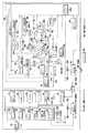
図1は本発明の一実施形態のプリントシステムを構成するデジタルカメラ(画像入力装置)とプリンタ(画像形成装置)とのそれぞれの内部構成の概略を示すブロック構成図である。
【0047】
図1に示すように本実施形態のプリントシステムは、デジタルカメラ等の画像入力装置(以下、デジタルカメラという)10と熱昇華型プリンタ等の画像形成装置(以下プリンタという)60との二つの装置を備え、両者はシリアルインターフェース規格の一つであるUSB(Universal Serial Bus)規格に準拠した所定の通信手段等によって電気的に接続されて互いに通信し得るように構成されている。そしてデジタルカメラ10とプリンタ60とにはそれぞれの動作を制御する制御手段(後述するDSCコントローラ13及びマイクロコンピュータ22)がそれぞれに備えられている。
【0048】
換言すると、本実施形態のプリントシステムは動作を制御する制御手段(13・22)が各備えられたデジタルカメラ10とプリンタ60とが機能的に結合されて構成されているものである。
【0049】
まず、デジタルカメラ10の内部を構成する主要構成部材について図1に基づき以下に説明する。
本実施形態のプリントシステムの一部を構成するデジタルカメラ10は、複数の光学要素等からなり被写体からの光束を集光して光学的な被写体像を形成する撮影光学系11と、光電変換素子(CCD;Charge-Coupled Device)センサ等の撮像素子)やその駆動回路等からなる撮像ユニット12と、画像入力装置としての機能を達成するために当該デジタルカメラ10の動作の統括的な制御を行なう制御手段であって例えばシステムLSI(Large Scale Integration;大規模集積回路)等により形成されるDSC(Digital Still Camera)コントローラ13と、本デジタルカメラ10における各種の設定や動作等を指示する指示信号等を発生させるための操作部材等(図示せず。本デジタルカメラ10の回路ユニットに含まれる電気的な構成部材であって例えば撮影動作の開始等を指示するレリーズボタンや電源の開閉状態を切り換える電源ボタン、画像の表示すべき画像データやプリントすべき所望の画像データの番号を選択指示するコマ番号選択ボタン等)に連動する複数のスイッチ部材からなり使用者による操作を受け付けるための複数の操作部(図示せず)に連動するカメラ操作スイッチ14と、本デジタルカメラ10によって取得した画像データに基づく画像や二次電池64(後述する。図2参照)の状態を含む各該当機能の状態をDSCコントローラ13の制御下で所定の表示部に表示出力する表示手段である液晶モニタ15と、画像データや各種データ等を一時的に記憶するメモリ即ち一時記憶手段であり半導体記憶素子であるSDRAM(エスディーラム;Synchronous Dynamic Random Access Memory)16と、電気的に書き換え可能な半導体メモリ(ロム;ROM;Read Only Memory))であるフラッシュロム(Flash ROM)17と、撮像ユニット12により取得しDSCコントローラ13により所定の信号処理がなされた画像データ等を所定の形態(例えばJPEG形式等の圧縮形態)で記録する半導体メモリ媒体(例えばSSFDC(Solid State Floppy Disk Card)やCF(Compact Flash)等)や磁気記録媒体又は光記録媒体等であって所要に応じて適用され得る記録メディア18と、本デジタルカメラ10とプリンタ60とを接続するための接続手段であってデジタルカメラ10の側からプリンタ60の側へと画像データ等を転送する画像データ伝送手段の一部を構成するUSBホストコントローラ19と、発音によって使用者に対して警告を発するための手段であるPCV61と、このPCV61をDSCコントローラ13の制御によって駆動する発音回路62と、充電式電池である二次電池64(図1には図示せず。後述の図2参照)等を含み、この二次電池64から供給される電力の制御等を行なう電気回路等からなるカメラ電源回路21と、プリンタ60側の接続端子58に連結されることで本デジタルカメラ10とプリンタ60とを接続するための接続手段の一部を構成する接続端子57等によって構成されている。
【0050】
DSCコントローラ13は、上述したように本デジタルカメラ10の統括的な制御を行なう制御手段である。そのためにDSCコントローラ13は、撮像ユニット12によって取得された被写体像の画像信号を受け取るCCDインターフェイス回路13aと、このCCDインターフェイス回路13aとSDRAM16との間に介在し両者を信号線によって電気的に接続するための手段であるメモリインターフェイス回路13bと、SDRAM16に一時的に記憶された画像データに基づいて所定の信号処理(画像サイズ変換処理等)が施された画像データを取り込みこれを液晶モニタ15の表示部によって表示し得る形態のデータに変換する信号処理等を行なうビデオエンコーダ回路13cと、後述するRISCコントローラ13fによって制御されSDRAM16に一時的に記憶された画像データに基づいて液晶モニタ15の表示解像度に適合した画像データとなるように画像のサイズを変換する画像サイズ変換回路13dと、画像データの符号化処理及び復号化処理等を行なう画像圧縮伸張回路13eと、本DSCコントローラ13の内部回路を司るリスク(RISC;Reduced Instruction Set Computer)コントローラ13f等を内部に有して構成されている。
【0051】
DSCコントローラ13は、上述したように本デジタルカメラ10の統括的な制御を行なうと共に、本デジタルカメラ10とプリンタ60とが接続されている状態においては当該プリントシステム全体の制御をも行ない得るようになっている。
【0052】
この場合においてDSCコントローラ13は、プリンタ60の側に設けられ当該プリンタ60の統括的な制御を司るマイクロコンピュータ22に対して各種の指示信号や所定の画像データ等を送信する制御を行なうようになっている。
【0053】
画像圧縮伸張回路13eによって行なわれる符号化処理は、SDRAM16に一時記憶された画像データに基づいて行なわれる処理であって、所定の形態の画像データ(例えばJPEG(Joint Photographic Expert Group)形式等の圧縮データ)を生成するための圧縮処理である。この符号化処理によって生成されたJPEG形式の画像データは、メモリインターフェイス回路13bを介して記録メディア18等へと伝送され、当該記録メディア18の所定の領域に記録されるようになっている。
【0054】
なお、生成されたJPEG形式の画像データは、記録メディア18の所定の領域に記録されるようにするのとは別に、これに代えて、例えばRISCコントローラ13fのプログラムコードが予め記録されているフラッシュロム17の一部の領域に対して当該生成された画像データを記録させ得るようにすることもできる。
【0055】
また、画像圧縮伸張回路13eにより行なわれる復号化処理は、記録メディア18の所定の記録領域に圧縮された所定の状態で記録されている画像データ(JPEGデータ等)をメモリインターフェイス回路13bを介して読み出した後、この読み出した画像データに対して所定の伸張処理を施す処理もある。この画像圧縮伸張回路13eにおいて伸張処理された画像データは、メモリインターフェイス回路13bを介してSDRAM16等に一時的に記憶され得るようになっている。
【0056】
このようにDSCコントローラ13は、撮像ユニット12により取得された被写体像を表わす画像信号を受けて、この画像信号に対して各種の画像信号処理等を施すことによって所定の形態の画像データを生成し得るように信号処理を行なう。こうして生成された画像データ等は、液晶モニタ15・SDRAM16・フラッシュロム17・記録メディア18・USBホストコントローラ19等の各対応する部材に対して適宜出力されるようになっている。
【0057】
なおDSCコントローラ13は、フラッシュロム17・記録メディア18・USBホストコントローラ19に対して外部バスライン20によって電気的に接続されている。これにより上述のDSCコントローラ13と各構成部材との間で画像データ等の送受信を相互に行ない得るようになっている。
【0058】
接続端子57は、上述したようにプリンタ60側の接続端子58と連結されることで当該プリントシステムを構成する二つの装置(デジタルカメラ10・プリンタ60)を連結する接続手段の一部を構成するものである。
【0059】
この接続端子57・58によってデジタルカメラ10とプリンタ60とが連結された状態では、両装置間において各種の情報や指示信号・制御信号等に加えて所定の形態に信号処理された画像信号等の送受信及びプリンタ60の側からデジタルカメラ10の側への電力の供給等が行なわれるようになっている。
【0060】
そのためにデジタルカメラ10の側の接続端子57は、デジタルカメラ10の内部においてUSBホストコントローラ19とカメラ電源回路21とに接続されている。
【0061】
なお本実施形態においては、図1に示すように接続端子57・58を例えば一対のコネクタ(端子)によって構成される例を示しているが、これに限らず例えば電源系コネクタとデータ伝送系のコネクタとを各別に設けたり、一般的な信号ケーブルによるケイブル接続によってデジタルカメラ10とプリンタ60とが連結され得るように構成してもよい。
【0062】
カメラ電源回路21は、本デジタルカメラ10が単独で動作するときには当該デジタルカメラ10の電源として機能するようになっている。そのために本カメラ電源回路21は、デジタルカメラ10の回路ユニットの電源ライン(図示せず)に電気的に接続されている。
【0063】
また、本デジタルカメラ10とプリンタ60とが接続端子57・58によって接続されたときには、プリンタ60の側のプリンタ電源回路55(後述する)は、接続端子57・58を介して本デジタルカメラ10のカメラ電源回路21に電気的に接続されることになる。この状態となったときにはプリンタ電源回路55は、デジタルカメラ10及びプリンタ60の両装置を含むプリントシステム全体への電力供給を担う電源として機能するようになっている。
【0064】
つまり、デジタルカメラ10とプリンタ60とが接続された状態で本実施形態のプリントシステムが動作するときには、プリンタ電源回路55から供給される電力は接続端子57・58を介してカメラ電源回路21へと供給され、これによって本プリントシステムが動作するようになっている。換言すればプリンタ電源回路55は、本実施形態のプリントシステムにおける主電源としての役目をするものであって、デジタルカメラ10への給電作用と二次電池64を充電する給電回路の役目をしている。
【0065】
さらに、本デジタルカメラ10とプリンタ60とが接続端子57・58によって接続されたときは、カメラ電源回路21の内部に設けられる二次電池64(図2参照)は、プリンタ電源回路55からの電力を接続端子57・58を介して受け得るようになっている。したがってこれによりプリンタ電源回路55は、デジタルカメラ10の二電池の充電をも行ない得るようになっている。
【0066】
次に、プリンタ60の内部を構成する主要構成部材について図1に基づき以下に説明する。
【0067】
本実施形態のプリントシステムの一部を構成するプリンタ60は、上述のデジタルカメラ10のDSCコントローラ13と連繋して画像形成装置としての機能を達成すべく当該プリンタ60を統括的に制御し内部にデジタルカメラ10の側からUSBホストコントローラ19(画像データ伝送手段)を介して供給される画像データを受信する画像データ受信手段であるUSBデバイスコントローラ22aを備えたマイクロコンピュータ22と、プリント動作に供するプリント用紙46を複数重ねて載置する用紙装填部である用紙トレイ45と、この用紙トレイ45が本プリンタ60の所定の位置に正しく装填されているか否かを検出する用紙トレイ検出スイッチ44と、プリント用紙46を所定のときに所定の方向へ適宜移動させ当該プリント用紙46を本プリンタ60の内部における所定の位置に配置する搬送動作を行なうための駆動源であって例えばステッピングモータ等の搬送モータ49と、マイクロコンピュータ22からの指示信号に基づいて搬送モータ49の駆動制御等を行なう搬送モータ駆動回路50と、搬送モータ49に連結され当該搬送モータ49の回転駆動力をプリント用紙46へと伝達するグリップローラ47と、このグリップローラ47に対向する位置に設けられ当該グリップローラ47との間にプリント用紙46を挟持して当該プリント用紙46の搬送動作を補助するピンチローラ48と、フォトリフレクタ(PR;Photo Reflecter)等の素子からなるセンサであってプリント用紙46の移動方向における当該プリント用紙46の位置を検出する用紙位置センサ51と、プリント用ヘッド部(サーマルヘッド38)のヘッド面をインクリボン33を挟んでプリント用紙46の印字面へと押しつけると共に当該プリント用紙46の搬送動作を補助するプラテンローラ52と、サーマルヘッド38を備えたヘッドアーム39のアップ/ダウン(UP/DOWN)駆動を制御するヘッド位置制御モータ41と、マイクロコンピュータ22からの指示信号に基づいてヘッド位置制御モータ41の駆動制御を行なうヘッドモータ駆動回路42と、ヘッド位置制御モータ41の回転軸に連結され当該ヘッド位置制御モータ41の回転駆動力をヘッドアーム39へと伝達しこれを図1の矢印X方向に揺動させるカム40と、フォトインタラプタ(PI)等の素子からなるセンサであってカム40の回転位置等を検出することでサーマルヘッド38の位置を検出するヘッド位置センサ43と、マイクロコンピュータ22から外部バスライン23を介して本プリンタ60の側に伝送されプリント動作に供する形態の画像データを一時的に記憶する内部メモリであるSRAM24と、このSRAM24に一時記憶されている画像データを読み出してサーマルヘッド38へと出力すると共に当該サーマルヘッド38を駆動制御するサーマルヘッド制御回路25と、プリント用紙46に対して所望のプリントを行なうための染料を塗布したインクリボン33を巻回して収納したインクリボンケース32と、フォトリフレクタ(PR)等の素子によって構成されるセンサであってインクリボン33の各フイルム(Y・M・C・保護;インクリボン33の詳細は後述する)の位置を検出するリボン位置検出センサ36と、サーミスタ等の素子によって構成されサーマルヘッド38の温度を検出する温度センサ37と、インクリボン33の巻き取り駆動を行なって当該インクリボン33を所定のときに適宜移動させるための駆動源であるリボンモータ30と、マイクロコンピュータ22からの指示信号に基づいてリボンモータ30の駆動制御を行なうリボンモータ駆動回路31と、フォトインタラプタ(PI)等の素子からなりインクリボン33の巻取動作が正しく実行されているか否かを検出するリボン移動検出センサ35と、インクリボン33の移動に連動して回転するように構成されたスリット付き円盤34と、リボンケース32が本プリンタ60の所定の位置に正しく装填されているか否かを検出するリボンケース検出スイッチ29と、プリンタ60における各種の設定や動作等を実行させるための複数の操作部材に連動し対応する所定の指示信号等を発生させ得るスイッチ部材であって本プリンタ60の回路ユニット(図示せず)に実装されるプリンタ操作スイッチ54と、本プリンタ60に関する各種の設定情報等が予め格納されている不揮発性メモリ53と、外部電源からの電力を本プリンタ60へと供給するための中継手段であるACアダプタ59と、このACアダプタ59を本プリンタ60に接続する端子である電源端子56と、ACアダプタ59から電源端子56を介して供給される電力を受けて本プリンタ60の回路ユニット(図示せず)に適合する電圧に変換した後の電力を当該回路ユニットへと送電するプリンタ電源回路55と、本プリンタ60の動作中に内部に生じる熱を外部に排出し装置内部を冷却するためのファン26と、このファン26を回転駆動させるファンモータ27と、このファンモータ27を駆動制御するファンモータ駆動回路28等によって構成されている。
【0068】
マイクロコンピュータ22は、デジタルカメラ10から送信される指示信号や画像データ等を接続端子57・58を介して受けて、これに基づき本プリンタ60のプリント動作等を制御するものである。つまり、マイクロコンピュータ22は、デジタルカメラ10の側からUSBホストコントローラ19(画像データ伝送手段)及び本プリンタ60のマイクロコンピュータ22のUSBデバイスコントローラ22a(画像データ受信手段)を介して供給される画像データに基づいて画像のプリントを実行するプリント手段としての機能を有してなるものである。なお、本実施形態のプリントシステムに適用されるプリンタ60は単独でプリント動作を実行することはできず、上述のデジタルカメラ10に結合された形態で動作する仕様となっている。
【0069】
また、マイクロコンピュータ22は複数のプリンタ操作スイッチ54に応じた各種の指示信号等を監視し、使用者によって実行された操作に各対応する駆動回路等の制御を行なうようになっている。
【0070】
ここでプリンタ操作スイッチ54は、上述したように複数の操作スイッチからなり、例えばプリント動作を開始すべき旨の指示を行なうプリント開始スイッチや本プリンタ60の電源の開閉(オン・オフ)指示を行なう電源スイッチ等を含んで構成されている。
【0071】
これらの複数のスイッチからなるプリンタ操作スイッチ54を作動させ得る操作部材は、プリンタ60の外装部材(図示せず)の所定の位置に各別に設けられており、デジタルカメラ10とプリンタ60とが接続された状態において、使用者が操作するものである。
【0072】
つまり、使用者がプリンタ60の所定の操作部材を操作することによって、プリンタ操作スイッチ54から対応する指示信号が発生し、これを受けてマイクロコンピュータ22は各対応する制御を行なうように構成されている。これにより使用者の所望する画像を対象とするプリント動作を実行させることができるようになっている。
【0073】
さらに、マイクロコンピュータ22は、ヘッド位置センサ43の出力に基づいてヘッドモータ駆動回路42を介してヘッド位置制御モータ41の制御を行ない、これによりサーマルヘッド38の位置を決定するようになっている。
【0074】
また、マイクロコンピュータ22は、用紙位置センサ51の出力に基づいて搬送モータ駆動回路50を介して搬送モータ49の制御を行なって、プリント用紙46の移動方向における当該プリント用紙46の位置を決定するようになっている。
【0075】
そして、マイクロコンピュータ22は、リボン移動検出センサ35の出力を監視することによってインクリボン33の巻取動作が正しく実行されているか否かを検出するようになっている。
【0076】
即ち、マイクロコンピュータ22は、インクリボン33の移動に連動して回転するスリット付き円盤34に対向する位置に配設されるリボン移動検出センサ35の出力を検出することでスリット付き円盤34の回転量を検出し、これによりインクリボン33の巻取動作を監視し得るようになっている。
【0077】
不揮発性メモリ53には、本プリンタ60に対する電力の供給が断たれた場合にも常に保持しておくべき所定の情報等が格納されている。その情報としては、例えば本プリンタ60による制御の履歴等を示す制御パラメータや本プリンタ60の特性を示すプリントパラメータ等である。
【0078】
そのために不揮発性メモリ53は、電気的に書き換え可能なロムであるEEPROM(Electrically Erasable Programmable Read-Only Memory)・強誘電体メモリであるFeRAM(Ferroelectric Random Access Memory)・電池バックアップ機能付きのSRAM(Static Random Access Memory)等の素子によって形成されている。
【0079】
搬送モータ49は、用紙トレイ45(用紙装填部)からプリント用紙46を取り出して(搬出して)当該プリント用紙46を所定のプリント開始位置、即ちサーマルヘッド38(プリント用ヘッド部)に臨む位置まで移動(移送)するための準備用搬送動作である給紙動作を行なったり、プリント動作の実行時にプリント用紙46を所定の速度で所定の方向に移動させるプリント用紙搬送動作、即ちサーマルヘッド38によって所定のプリント動作を行なうべく当該プリント用紙46とサーマルヘッド38との間に相対的な位置変化を起こさせるための搬送動作や、プリント動作終了時にプリント用紙46を本プリンタ60の外部へと排出する排紙動作等のプリント用紙搬送動作に寄与するプリント用紙搬送手段の一部を構成する部材である。そして、プリント用紙46の搬送動作時には、当該プリント用紙46はグリップローラ47とピンチローラ48とに挟持されることで位置ズレ等が生じないように確実に保持されるようになっている。
【0080】
なお、当該プリンタ60におけるプリント用紙搬送手段は、搬送モータ49・搬送モータ駆動回路50・グリップローラ47・ピンチローラ48等等の構成部材により構成されるものである。
【0081】
グリップローラ47は、搬送モータ49によって駆動されるようになっている。また、この搬送モータ49の駆動電力は、搬送モータ駆動回路50から供給されるようになっている。そしてマイクロコンピュータ22は、搬送モータ駆動回路50に対して所定の制御信号を送ることでプリント用紙46を任意に搬送することができるようになっている。
【0082】
リボンケース32に収納されるインクリボン33は、プリント用紙46に対して熱転写される染料(Y(イエロー)・M(マゼンタ)・C(シアン)の各色)が塗布された転写フイルムと保護層を形成するための転写フイルム等によって構成されている。
【0083】
このインクリボン33における各フイルム(Y・M・C・保護層)のそれぞれには検出用の所定の形態のマークが形成されている。リボン位置検出センサ36は、このマークを検出することによって当該インクリボン33の各フイルムの位置を検出するようになっている。
【0084】
プリンタ電源回路55は、上述したように電源端子56を介してACアダプタ59に接続されるようになっており、これにより外部電源からの供給を受け得るようになっている。
【0085】
そして、プリンタ電源回路55は、本プリンタ60の内部において回路ユニットの電源ライン(図示せず)に電気的に接続されている。したがってこれにより外部電源からの電力は、ACアダプタ59・電源端子56を介してプリンタ電源回路55へ供給され、このプリンタ電源回路55において所定の電圧変換がなされた後、当該電力は回路ユニットへと送電され分配されるようになっている。
【0086】
なお、SRAM24は後述するようにデジタルカメラ10の側から転送されてくるデータを受信して、これを一時的に記録する半導体素子(メモリ)によって構成されている。
【0087】
また、SRAM24及びサーマルヘッド制御回路25はマイクロコンピュータ22に対して外部バスライン23によって電気的に接続されている。
【0088】
次に、本実施形態のプリントシステムにおいてデジタルカメラとプリンタとが接続する接続部位の構成と、当該デジタルカメラ及びプリンタに各備えられる電源回路の構成とを図2を用いて以下に詳述する。
【0089】
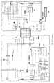
図2は本実施形態のプリントシステムにおけるデジタルカメラとプリンタとが接続する接続部位の構成及び両者の各電源回路(カメラ電源回路21・プリンタ電源回路55)の構成の内部概略を示すブロック構成図である。
【0090】
本実施形態のプリントシステムにおいてこれを構成するデジタルカメラ10とプリンタ60とを接続するための接続手段は、上述したようにデジタルカメラ10の側に設けた接続端子57とプリンタ60の側に設けた接続端子58とによって構成されている。
【0091】
両接続端子57・58の内部には、6つの信号ラインVbus・D+・D−・GND・CHG・PGNDが配設されている。このうちVbus・D+・D−・GNDの4つの信号ラインは、USB規格において必要な信号ラインとなっている。これに加えて、本実施形態における接続手段では、CHG・PGNDの二つのラインが設けられている。この二つの信号ラインは、プリンタ60の側からデジタルカメラ10の側へ向けて動作に必要な電力を供給するためのラインとなっている。
【0092】
詳述するとCHGは、デジタルカメラ10を動作させるための動作電力とデジタルカメラ10の二次電池64を充電するための電力とをプリンタ60の側からデジタルカメラ10側へと供給するためのライン(第1の給電線)である。そのために当該CHGはUSB規格に準拠した上述の4つの信号ライン(Vbus・D+・D−・GND)に比べて電力容量が大きいものとなっている。したがって、電力容量の大きいCHGに対応してUSB信号ラインとは別の専用グランドラインとしてPGNDが配線されている。
【0093】
通常のUSB規格においては、第2の給電線となるVbusラインを利用することによってホスト側からターゲットとなる機器側へと電力を供給することができるように構成されている。これに対して、本実施形態のプリントシステムにおいては、ターゲット機器となるプリンタ60の側からホストとなるデジタルカメラ10の側に向けて電力を供給するように構成されている。またプリンタ60は、自己の電力源から供給される電力によって動作することができるように構成されている。このことから本プリントシステムにおいては、Vbusを電力供給用ラインとしては利用せずに、これを信号通信インターフェイスを構成するために使用し得るように構成されている。
【0094】
デジタルカメラ10の側において、DSCコントローラ13とサブコントローラ63とはシリアル通信ラインによってデータ交換が可能となるように構成されている。そして当該サブコントローラ63はDSCコントローラ13からの指示信号に基づいて二次電池64の管理を行なうようになっている。つまり、サブコントローラ63は、二次電池64の状態を検出及び管理して当該検出によるデータをDSCコントローラ13に供給する電池管理回路部の役目をしている。
【0095】
抵抗R04は電池電圧を測定する際に必要となるダミーロード抵抗であり、Q01を介して二次電池64からダミーロード抵抗へ電流を流すことができるようになっている。このダミーロード抵抗によって二次電池64の電圧を測定するようになっている。
【0096】
サブコントローラ63のIOポートP_ContRはQ01に接続されていて、当該IOポートP_ContRによってQ01のオン・オフの制御を行ない得るようになっている。また、抵抗R6・R5は二次電池64の電圧をサブコントローラ63の内部に具備されるADコンバータ63aの入力レンジに変換するための抵抗である。
【0097】
またデジタルカメラ10の内部には、二次電池64の温度を検出するための手段としての温度検出センサー67が配設されている。この温度検出センサー67の出力はサブコントローラ63のADコンバータ63aに入力されるようになっている。そしてサブコントローラ63は温度検出センサー67からの出力を受けて二次電池64の温度を測定することができるようになっている。
【0098】
デジタルカメラ10とプリンタ60とが接続されている状態においては、接続端子57・58のCHGラインを介して入力される電力は定電流回路66を介して二次電池64へと入力されるようになっている。この場合において、サブコントローラ63はIOポートP_ContCによって定電流回路66のオン・オフ制御を行なうようになっている。これにより当該二次電池64の充電が行なわれるようになっている。したがって、デジタルカメラ10の側のカメラ電源回路21は、プリンタ60の側から給電を受けてデジタルカメラ10の電源として適用される二次電池64を充電するための充電回路としての機能を有している。
【0099】
デジタルカメラ10のDC/DCコンバータ65Aは、DSCコントローラ13による制御下で動作するようになっており、入力された電力の電圧をデジタルカメラ10の内部の回路ユニットが必要とする電圧となるように変換して出力する。そして、当該DC/DCコンバータ65Aは、デジタルカメラ10とプリンタ60とが接続されているときには、接続端子57・58のCHGラインを介して入力される電圧を変換するようになっている。またデジタルカメラ10とプリンタ60とが接続されていないときには、デジタルカメラ10に内蔵される充電式電池である二次電池64から供給される電力の電圧を変換するようになっている。なお、この二次電池64はデジタルカメラ10が単独で動作する際の電源となっている。またDC/DCコンバータ65Aの出力の一つは、トランジスタQ00を介してデジタルカメラ10の側の接続端子57のVbusへ接続されている。
【0100】
さらに、DSCコントローラ13は、IOポートP_ContVbusから制御信号を出力することによりトランジスタQ00のオン・オフ制御を行なうことができるようになっている。
【0101】
また、接続端子57・58の信号ラインD+・D−は、差動型の信号ラインを構成している。そして、USBホストコントローラ19とマイクロコンピュータ22の内部に設けられるUSBデバイスコントローラ22aとは、この一対の信号ラインD+・D−を用いることによってデータの送受信を行なうことができるようになっている。この信号ラインD+・D−は、デジタルカメラ10側においては抵抗R00・R01によりそれぞれプルダウン(Pull Down)されている。したがってデジタルカメラ10とプリンタ60とが接続されていない状態では、信号ラインD+・D−はロー(Low)レベルとなる。一方、プリンタ60の側では信号ラインD+あるいはD−の何れか一方をハイ(Hi)レベルに設定することでUSBホストコントローラ19に対してデータ転送速度を告知することができるようになっている。
【0102】
またCHGの出力は、抵抗R02・R03によって分圧された後、DSCコントローラ13のIOポートであるP_DetChgに入力されるようになっている。したがってDSCコントローラ13は、IOポートP_DetChgを監視することによってデジタルカメラ10とプリンタ60とが接続されたか否かを検出することができるようになっている。
【0103】
一方、プリンタ60側のプリンタ電源回路55(図1参照)は、図2に示すようにDC/DCコンバータ65Bを備えており、このDC/DCコンバータ65Bは電源端子56を介して接続されるACアダプタ59からの出力を当該プリンタ60の内部に設けられる回路ユニットが必要とする電圧に変換して出力するように構成されている。
【0104】
この場合において、プリンタ電源回路55のDC/DCコンバータ65Bの一部のラインはトランジスタQ10を介してプリンタ60の側の接続端子58のCHGに接続されている。トランジスタQ10は、マイクロコンピュータ22のIOポートP_ContChgに接続されており、これによってトランジスタQ10のオン・オフ制御がなされてデジタルカメラ10への電力の供給が制御されている。
【0105】
作動信号ラインD+・D−の何れか一方をプルアップすることによってデータ転送速度を告知することができるようになっており、本実施形態においてはフルスピード(12Mbps)で通信が行なわれるようになっている。したがって、信号ラインD+をプルアップすることになるが、そのためにトランジスタQ11と抵抗R12がD+側に接続されている。
【0106】
トランジスタQ11はマイクロコンピュータ22のIOポートP_PullD+に接続されており、これによりオン・オフ制御がなされるようになっている。このようにトランジスタQ11をオン・オフ制御することによりD+ラインのプルアップを制御することができるようになっている。
【0107】
USB通信ラインを確立する(オープンする)に際してはDSCコントローラ13はVbusラインをロー状態からハイ状態へと設定する。このレベル変化は、マイクロコンピュータ22のIOポートP_DetVbusを監視することによって取得することができるようになっている。そして、Vbusの出力レベルをIOポートP_DetVbusの入力レベルに適合させるためにVbusラインには抵抗R10・R11が接続されている。
【0108】
以上のように構成された本実施形態のプリントシステムの作用を以下に説明する。
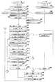
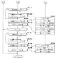
図3・図4・図5は、本実施形態のプリントシステムの作用を示し、デジタルカメラとプリンタとが接続された状態にあるときの当該プリントシステムにおけるメインルーチンのフローチャートである。
【0109】
なお、図3〜図5においてはデジタルカメラ側のDSCコントローラ(13)の動作処理とプリンタ側のマイクロコンピュータ(22)の動作処理とを並べて示し、互いに通信したり連繋して動作する際の様子が容易にわかるように図示している。
【0110】
まず、本実施形態のプリントシステムのメインルーチンについて図3〜図5に基づいて以下に説明する。
【0111】
このプリントシステムのメインルーチンはデジタルカメラ10及びプリンタ60に各備えられる電源回路21・55のそれぞれがオン状態に切り換わることで一連の処理が開始される。
【0112】
この場合において、デジタルカメラ10とプリンタ60とが接続されている状態にあるときには、プリンタ60のプリンタ電源回路55のオン・オフ状態を切り換えるための所定の操作部材(図示せず;プリンタ側主電源操作部材という)を使用者が操作することによってプリンタ電源回路55がオン状態に切り換わる。このプリンタ電源回路55は、上述したようにデジタルカメラ10のカメラ電源回路21に連動するように構成されていることから、プリンタ電源回路55がオン状態に切り換わるのと同時にカメラ電源回路21もオン状態に切り換わる。
【0113】
一方、カメラ電源回路21は、当該デジタルカメラ10に設けられカメラ電源回路21のオン・オフ状態を切り換えるための所定の操作部材(図示せず;カメラ側主電源操作部材という)を使用者が操作することによってもオン状態に切り換わる。
【0114】
このようにしてデジタルカメラ10のカメラ電源回路21がオン状態に切り換わると、デジタルカメラ10の側ではDSCコントローラ13の制御によって図3に示すステップS1の処理が実行される。このステップS1においては、デジタルカメラ10の起動時における初期設定処理、即ちコントローラ内部レジスタ・IOポートの初期化・周辺回路の初期設定処理等が実行されることになる。その後、ステップS2の処理に移行する。
【0115】
一方、デジタルカメラ10とプリンタ60とが接続されている状態であって、プリンタ側主電源操作部材によってプリンタ電源回路55がオン状態に切り換わりこれに連動してカメラ電源回路21もオン状態に切り換わった場合には、まずプリンタ電源回路55からCHGラインを介してカメラ電源回路21への電力供給処理が行なわれた後、デジタルカメラ10のDSCコントローラ13が起動して、当該デジタルカメラ10の起動時の初期設定処理(上述の各処理等)がステップS2の処理において実行される。これと同時にDSCコントローラ13はプリンタ60のマイクロコンピュータ22に対して所定の指示信号を発し、これを受けてマイクロコンピュータ22はステップS91に示すようにプリンタ60の起動時の初期設定を実行する。その後、プリンタ60は待機状態となる一方、デジタルカメラ10は次のステップS2の処理に移行する。
【0116】
ステップS2において、DSCコントローラ13はデジタルカメラ10とプリンタ60とが接続状態にあるか否かの確認を行なう。デジタルカメラ10とプリンタ60とが接続状態にある場合には、CHGの出力が抵抗R02・R03によって分圧された後、DSCコントローラ13のIOポートP_DetChgに入力される。これによりIOポートP_DetChgはハイ(Hi)レベルとなる。
【0117】
つまり、このステップS2において、DSCコントローラ13はIOポートP_DetChgの入力レベルを監視することによって、デジタルカメラ10とプリンタ60とが接続状態にあるか否かの判断を行なう。この場合において、IOポートP_DetChgがハイ(Hi)レベルであることが検出された場合には、デジタルカメラ10とプリンタ60とが接続状態にあるものと判断されて、次のステップS3の処理に進み、このステップS3以降の処理において、当該デジタルカメラ10とプリンタ60とが協働して動作するプリンタシステムを構成するための処理が実行される。
【0118】
また、上述のステップS2において、DSCコントローラ13がIOポートP_DetChgがロー(Lo)レベルであることを検出した場合には、デジタルカメラ10とプリンタ60とが接続状態にないものと判断されて、DSCメインルーチン(図14参照)に移行する。このサブルーチンはデジタルカメラ10が単独で画像入力装置であるカメラとして動作するための処理ルーチンである。この処理ルーチンについての詳細は後述する。
【0119】
上述のステップS2の処理において、デジタルカメラ10とプリンタ60とが接続状態にあると判断された場合には、上述したように両者が協働して動作するプリンタシステムが構成される。そのためには、両者間の通信回線を確立する(オープンする)必要がある。
【0120】
そこでステップS3において、DSCコントローラ13はUSBホストコントローラ19の所定の初期設定処理を実行する。これと同時に、DSCコントローラ13はプリンタ60のマイクロコンピュータ22に対して所定の指示信号を送信する。その後、ステップ4の処理に進む。
【0121】
一方、上述のステップS3の処理によってDSCコントローラ13から送信された所定の指示信号を受けてマイクロコンピュータ22は、ステップS92において、USBデバイスコントローラ22aの所定の初期設定処理を実行する。その後、プリンタ60は待機状態となる。
【0122】
次に、ステップS4において、DSCコントローラ13はサブコントローラ63に対して電池の残容量についての情報を要求し、これを取得する。ここで、サブコントローラ63は、上述のように電池残容量情報についてのDSCコントローラ13からの通信要求を受けると、ダミーロード(ダミー負荷)を駆動して、その状態の二次電池64の電圧値を測定し、その測定結果から電池残容量を計算し、その結果得られた電池残容量についての情報をDSCコントローラ13へ送信する。その後、ステップS5の処理に進む。なお、ここで行なわれるサブコントローラ63による処理は、後述するステップS302の処理である(図19参照)。
【0123】
なお、この場合においては、デジタルカメラ10に二次電池64が装填されていない状態でもプリンタ電源回路55から電力が供給されている状態にあれば、デジタルカメラ10の側の電気回路は動作している状態にある。この状態に有るときには、サブコントローラ63はデジタルカメラ10に二次電池64が装填されているか否かの確認を行なう。そして、二次電池64がデジタルカメラ10に装填されていない状態にあることが確認された場合には、その旨の情報をDSCコントローラ13へと送信する。
【0124】
ステップS5において、DSCコントローラ13はサブコントローラ63から取得した電池残容量情報に基づいて二次電池64の充電動作を行なう必要があるか否かが確認を行なう。ここで充電動作が必要であると判断された場合には、次のステップS6の処理に進む。
【0125】
ステップS6において、DSCコントローラ13は充電動作中フラグを「1」に設定(セット)して、次のステップS7の処理に進み、このステップS7において、DSCコントローラ13はサブコントローラ63に対して充電動作を開始させる旨の指令信号を送信する。なお、上述のステップS6の処理においてセットされる充電動作中フラグは当該充電動作が終了するまでクリア(「0」)されないようになっている。この指令信号を受けてサブコントローラ63は後述するステップS315の処理を実行する(図20参照)。
【0126】
一方、上述のステップS5において、DSCコントローラ13はサブコントローラ63から取得した電池残容量情報に基づいて二次電池64の充電動作は不要であると判断した場合には、次のステップS8の処理に進む。
【0127】
ステップS8において、DSCコントローラ13は液晶モニタ15を用いて二次電池64の充電状態に関する情報等を表示する表示処理を実行する。その後、ステップS9の処理に進む。
【0128】
なお、ここで液晶モニタ15に表示されるべき二次電池64の充電状態に関する情報等の表示例を図6〜図8に基づいて以下に説明する。
【0129】
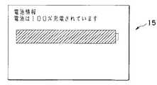
まず、サブコントローラ63から取得した情報によって電池容量が既に満充電状態(100%充電状態)である旨を示す場合には、例えば図6に示すような形態の表示が液晶モニタ15の表示部になされる。
【0130】
この図6に示す表示形態では、二次電池64情報についての詳細を表わす文字列と、当該二次電池64を模したバーグラフによる画像とからなる表示形態によって、当該二次電池64が満充電状態であることが告知される表示例である。このように二次電池64の充電状態情報は、文字列及び画像等によって液晶表示モニタ(以下、単に液晶モニタという)15に表示されることによって、使用者が液晶モニタ15を視認するのみで容易に二次電池64情報を確認することができるようになっている。
【0131】
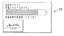
一方、サブコントローラ63から取得した情報によって電池容量が100%未満である旨を示す場合には、例えば図7に示すような形態の表示が液晶モニタ15の表示部になされる。
【0132】
この図7に示す表示形態では、電池容量が100%未満である旨を示す場合として、例えば電池容量が満充電状態に対して40%の容量となっている場合を示しており、その表示形態は図6に準じた形態となっている。つまり、上述の図6と同様に二次電池64情報の詳細を表わす文字列と、当該二次電池64を模したバーグラフによる画像との表示形態に加えて、例えば充電動作を実行したときに満充電状態になるまでの推定時間等を表示している。ここで、満充電までの推定時間は、サブコントローラ63によって算出される推測値である。なお、図7にも示すように二次電池64の残容量が所定のレベル以下であるような場合(例えば50%以下)には、さらに急速充電動作を開始する旨の告知を文字列によって表示している。
【0133】
他方、サブコントローラ63から取得した情報によって二次電池64がデジタルカメラ10に装填されていないと判断された場合には、例えば図8に示すような形態の表示が液晶モニタ15によってなされる。
【0134】
図8に示す表示形態では、デジタルカメラ10に二次電池64が装填されていないために充電動作を実行することができない旨の警告を文字列によって表示するものである。なお、この図8に示す警告表示を液晶モニタ15を利用して表示するのと同時に、これに連動させてPCV61を制御することで所定の警告音等を発生させるようにしてもよい。
【0135】
このように上述のステップS8の処理、即ち液晶モニタ15による所定の表示処理が実行された後、次のステップS9に進むと、このステップS9において、DSCコントローラ13は表示状態データに「#1」を設定する。その後、次のステップS10の処理に進む。
【0136】
ここで、表示状態データは、液晶モニタ15の表示状態を示すデータであって、DSCコントローラ13の内部メモリ(図示せず)の特定のアドレスに割り付けられ適宜保持されるデータである。
【0137】
なお、表示状態データが「#0」のときは、液晶モニタ15は表示動作を行なっていない、つまり何の表示もなされていないことを示すものとする。この状態は、例えばデジタルカメラ10が電源オン状態にあるときに、所定の時間の間、何の操作もなされなかった場合に切り換わるものである。
【0138】
また、表示状態データが「#1」のときは、液晶モニタ15には二次電池64に関する所定の情報が表示されていることを示すものとする。
【0139】
そして、表示状態データが「#2」のときは、液晶モニタ15には使用者が選択した所定の画像データに基づく画像が表示されていることを示すものとする。
【0140】
次に、ステップS10において、DSCコントローラ13は液晶モニタ15に所定の表示を行なう表示時間を規定するための内部タイマー(以下表示タイマーという)に「#Tdata1」を設定し、計時(カウント)動作を開始させる。この「#Tdata1」は液晶モニタ15に二次電池64情報等の表示を行なうための表示時間(第1の時間)を示すパラメータとしている。
【0141】
ここで、例えば使用者が所定の操作部材の操作を行なった場合には、その操作部材からの割り込み指示信号によって計時動作は中断されて液晶モニタ15の表示が停止するようになっている。また、設定された所定時間が経過するまでの間に使用者が所定の操作部材の操作を行なわなかった場合、つまり所定の割り込み信号の発生が無いまま表示タイマーに設定したカウント値が「#Tdata1」に到達すると、その時点で液晶モニタ15の表示が停止するようになっている。
【0142】
つまり、上述の「#Tdata1」で設定される第1の時間は、二次電池64の状態を表わす表示が液晶モニタ15の表示部に表示されているときに、デジタルカメラ10に対して何等の操作も行なわれないときに当該表示をオフにするための条件としての所定の規定時間である。
【0143】
このようにして、液晶モニタ15の表示が停止された後、次のステップS11の処理に進む。
【0144】
ステップS11において、DSCコントローラ13はマイクロコンピュータ22に対してプリンタ操作スイッチ54の状態情報を要求する指令(コマンド)を転送し、その情報を取得する。
【0145】
この場合において、待機状態にあったマイクロコンピュータ22は、DSCコントローラ13から指令(プリンタ操作スイッチ54の状態情報の要求指令)を受信すると、ステップS93において、プリンタ操作スイッチ54の状態情報を収集し、これをDSCコントローラ13に向けて送信する。
【0146】
なお、ここでDSCコントローラ13とマイクロコンピュータ22との間で行なわれる信号送受信動作は、USB転送形態の一つであるインターラプト転送を利用して所定の周期で実行されるようになっている。
【0147】
そして、上述したようにDSCコントローラ13はマイクロコンピュータ22からのプリンタ操作スイッチ54の状態情報を受信して、これを取得した後、次のステップS12の処理に進む。
【0148】
ステップS12において、DSCコントローラ13はカメラ操作スイッチ14の状態情報を読み込む。その後、ステップS13の処理に進む。
【0149】
ステップS13において、DSCコントローラ13は充電動作が実行されているか否かの判定を充電動作中フラグの状態確認によって行なう。ここで、充電動作中フラグが「0」であることを確認した場合には、充電動作の実行中ではないと判断してステップS15の処理に進む。
【0150】
また、充電動作中フラグが「1」であることを確認した場合には、充電動作の実行中であると判断して、次のステップS14の処理に進み、このステップS14において、DSCコントローラ13は充電情報の送信をサブコントローラ63に対して要求する指令を発する。サブコントローラ63は当該要求指令に対して現在の電池容量と充電時間等の情報をDSCコントローラ13に向けて送信する。これによりDSCコントローラ13に対してサブコントローラ63から所定の充電情報が入力される。その後、ステップS15の処理に進む。
【0151】
このように充電動作の実行中には、上述のステップS14の処理が周期的に実行されるようになっているので、DSCコントローラ13は二次電池64の状態を常に監視できるようになっている。
【0152】
続いて、ステップS15において、DSCコントローラ13はカメラ操作スイッチ14のうちのズームスイッチ(ZoomSW)に連動する操作部材(図示せず)が操作されたか否かの確認を行なう。このズームスイッチは、当該デジタルカメラ10が単独でカメラとして動作する際には、撮影光学系の変倍動作を指示するための操作部材に連動する操作スイッチである。
【0153】
また、これとは別に当該デジタルカメラ10がプリンタ60と協働して動作する場合には、当該ズームスイッチは、デジタルカメラ10の記録メディア18に記録済みの画像データに基づく画像を液晶モニタ15を利用して表示する際の表示画像の切り換え等を指示する操作スイッチとして作用するようになっている。つまり、使用者が液晶モニタ15を観察しながら所定の操作部材を操作することで、この操作部材に連動するズームスイッチからの指示信号に応じて液晶モニタ15に表示すべき画像の切り換えが行なわれる。これにより、所望の画像を簡単に液晶モニタ15に表示させることができるようになっている。
【0154】
このステップS15において、ここで、ズームスイッチ(ZoomSW)からの指示信号が確認されて所定の操作部材が使用者による操作がなされたと判断された場合には、ステップS16の処理に進む。一方、ズームスイッチ(ZoomSW)からの指示信号が確認されず、所定の操作がなさていないと判断された場合には、ステップS19の処理に進む。
【0155】
ステップS16において、DSCコントローラ13はズームスイッチからの指示信号に応じて液晶モニタ15に表示すべき画像の表示切り換え処理を行なう。この場合において、ズームスイッチからの指示信号がアップ(UP)方向である場合には、液晶モニタ15において現在表示中の画像のコマ番号に対して所定数だけ加算したコマ番号(例えば+1)に対応する画像を表示するための表示切り換え処理を行なう。また、ズームスイッチからの指示信号がアップ(DOWN)方向である場合には、液晶モニタ15において現在表示中の画像のコマ番号に対して所定数だけ減算したコマ番号(例えば−1)に対応する画像を表示するための表示切り換え処理を行なう。その後、ステップS17の処理に進む。
【0156】
ステップS17において、DSCコントローラ13は上述のステップS16の処理で指定されるコマ番号に対応する画像の画像データを記録メディア18から読み出す画像データ読み出し動作を実行する。その後、ステップS18の処理に進む。
【0157】
ステップS18において、DSCコントローラ13は上述のステップS17の処理で読み出した画像データ(圧縮形態のデータ、例えばJPEGデータ等)の復号化動作を実行する。その後、ステップS30の処理に進む。
【0158】
ステップS30において、DSCコントローラ13は上述のステップS17の処理で読み出しステップS18の処理で復号化した画像データに対応する画像を液晶モニタ15に表示する処理を実行する。その後、ステップS31の処理に進む。
【0159】
ステップS31において、DSCコントローラ13は表示状態データに「#2」を設定する。その後、次のステップS32の処理に進む。ここで、表示状態データ「#2」は、上述したように液晶モニタ15に使用者が選択した所定の画像データに基づく画像が表示されていることを示す。
【0160】
なお、上述のステップS30において液晶モニタ15に新規の画像が表示される以前の当該液晶モニタ15の状態としては、例えば
液晶モニタ15に何も表示がなされていない状態(表示状態データ「#0」)、
液晶モニタ15に二次電池64情報が表示されている状態(表示状態データ「#1」)、
液晶モニタ15に使用者が選択した画像が表示されている状態(表示状態データ「#2」)、
等がある。上述のステップS30においては、以前の液晶モニタ15の状態が上述の何れの状態にあっても、新規の選択画像が液晶モニタ15に表示されることになる。
【0161】
図9は、上述のステップS30の処理が実行された場合に液晶モニタ15に表示される画像表示の一形態を示している。
【0162】
図9に示すようにこの表示形態では、液晶モニタ15の表示領域全体を用いて選択された画像データに対応する画像が表示され、当該画面中の所定の位置に当該画像データに含まれる画像附帯情報、例えばコマ番号や日付データ等の各種の情報が文字列等によって表示される。この場合において、当該画像附帯情報は例えばOSD(On-Screen Display)機能等を利用して画像に重畳させて表示されている。
【0163】
続いてステップS32において、DSCコントローラ13は表示タイマーに「#Tdata2」を設定し、計時(カウント)動作を開始させる。この「#Tdata2」は液晶モニタ15に画像の表示を行なう表示時間(第2の時間)を示すパラメータとしている。
【0164】
ここで、表示タイマーに設定された所定時間が経過するまでの間に使用者が所定の操作部材の操作を行なわなかった場合、つまり所定の割り込み信号の発生が無いまま表示タイマーに設定したカウント値が「#Tdata2」に到達すると、その時点で液晶モニタ15の表示が停止するようになっている。
【0165】
つまり、上述の「#Tdata2」で設定される第2の時間は、デジタルカメラ10の液晶モニタ15の表示部に、プリントの対象乃至はその候補とする画像の表示が行なわれているときに、デジタルカメラ10に対して何等の操作も行なわれないときに当該表示をオフにするための条件としての所定の規定時間である。
【0166】
このようにして液晶モニタ15の表示が停止されると、その後、上述のステップS11の処理に戻り、以降の処理を繰り返す。
【0167】
一方、上述のステップS15の処理において、ズームスイッチからの指示信号が確認されずに、ステップS19の処理に進むと、このステップS19において、DSCコントローラ13はプリント許可スイッチ(SW)の状態を確認する。このプリント許可スイッチの状態は上述のステップS11の処理においてプリンタ60のマイクロコンピュータ22から取得したプリンタ操作スイッチ54の状態情報に含まれる情報である。ここで、プリント許可スイッチからの指示信号が発生していることが確認されると、次のステップS20の処理に進む。また、プリント許可スイッチからの指示信号が発生していない状態であることが確認されると、図4に示すステップS23の処理に進む。
【0168】
上述のステップS19の処理においてプリント許可スイッチからの指示信号が発生していることが確認されて、ステップS20の処理に進むと、このステップS20において、DSCコントローラ13はプリントを所望する画像データが選択されているか否かの確認を行なう。ここで、画像データの選択がなされていなければプリント動作を実行することはできない。したがって、この場合には図4のステップS23の処理に進む。このような状況になるのは、例えばプリントを所望する画像データの選択動作を実行することなくプリント許可スイッチに連動する所定の操作部材を操作したとき等である。
【0169】
一方、上述のステップS20において、プリントを所望する画像データの選択がなされていることが確認された場合には、次のステップS21の処理に進む。
【0170】
ステップS21において、DSCコントローラ13は表示状態データに「#2」が設定されているか否かの確認を行なう。ここで、表示状態データに「#2」が設定されている場合には、液晶モニタ15にはプリントを所望する画像データ、即ち選択された画像データに対応する画像が表示されている状態に有る。この場合には次のステップS22の印刷処理に進む。なお、このステップS22の印刷処理は、プリンタ60のマイクロコンピュータ22と協働して動作する処理であって、マイクロコンピュータ22の側では同時にステップS94の処理が実行される。このステップS22・S94において実行される印刷処理の詳細については後述する(図15〜図18参照)。
【0171】
そして、このステップS22の処理が終了すると、その後、上述のステップS32の処理に進む。
【0172】
一方、上述のステップS21において、表示状態データに「#2」が設定されていないことが確認されると、プリント動作の実行が禁止されて、上述のステップS30の処理に進む。ここで、例えば表示状態データに「#0」が設定されている場合には液晶モニタ15には何の表示もなされていない。また、表示状態データに「#1」が設定されている場合には液晶モニタ15には二次電池64情報が表示されている状態である。このような状態ではプリント動作が行われないようになっている。つまり、使用者はプリント動作を実行させる前に、液晶モニタ15を観察してプリントを所望する画像データに対応する画像が表示されているか否か、またプリントすべき画像の確認を行なわしめるのが至便である。そこで、この場合(表示状態データが「#2」以外の場合)には、今回行なったプリント許可スイッチの指示信号を無効扱いにして、上述のステップS30の処理に進み、以降の処理において、プリントを所望する画像データに対応する画像を液晶モニタ15に表示させ(S30)、表示状態データを「#2」に設定し(S31)、表示タイマーに「#Tdata2」を設定しカウントを開始させ(S32)る一連の処理を実行し、印刷処理を実行し得る状態となる。
【0173】
上述のステップS19の処理においてプリント許可スイッチからの指示信号が発生していない状態であることが確認された場合及び上述のステップS20の処理において画像データの選択がなされていない状態であると確認された場合に図4のステップS23の処理に進むと、このステップS23において、DSCコントローラ13はプリンタ電源スイッチ(SW)の状態を確認する。このプリンタ電源スイッチの状態は上述のステップS11の処理においてプリンタ60のマイクロコンピュータ22から取得したプリンタ操作スイッチ54の状態情報に含まれる情報である。
【0174】
ここで、プリンタ電源スイッチからの指示信号が発生していることが確認され、プリンタ電源がオン状態にあると判断された場合には、図5に示すステップS33の処理に進む。また、プリンタ電源スイッチからの指示信号が発生していないことが確認され、プリンタ電源がオフ状態にあると判断された場合には、次のステップS24の処理に進む。
【0175】
ステップS24において、DSCコントローラ13は液晶モニタ15の表示を停止させる処理を行なう。その後、ステップS25の処理に進む。
【0176】
ステップS25において、DSCコントローラ13は充電動作中フラグの状態を確認する。ここで、充電動作中フラグが「0」である場合には充電動作が終了したものと判断されてステップS28の処理に進む。また、充電動作中フラグが「1」である場合には、充電動作が未だ完了していない状態(未完了状態)にあると判断されて、次のステップS26の処理に進む。
【0177】
ステップS26において、DSCコントローラ13はサブコントローラ63との間で通信を行なって当該サブコントローラ63から所定の充電情報を取得する。その後、ステップS27の処理に進む。
【0178】
ステップS27において、DSCコントローラ13はサブコントローラ63から充電動作が終了した旨の情報を受けるまで待機する。そして、サブコントローラ63からの充電動作完了情報を受信した場合には、次のステップS28の処理に進む。
【0179】
この場合において、使用者がプリンタ60の電源スイッチ、即ち本プリントシステムの電源状態をオフ状態にするための操作を行なったときに、二次電池64の充電動作が未だ終了していない未完了状態であれば、当該プリントシステムの電源状態をオフ状態にすることなく、充電動作を継続して行なうようにしておく必要がある。
【0180】
そこで、ステップS26〜S27の処理でDSCコントローラ13はサブコントローラ63との間で通信を行なって、当該サブコントローラ63から充電動作が終了した旨の情報を受けるまで待機する処理ルーチンを設けている。
【0181】
そして、ステップS28において、DSCコントローラ13はシステムを停止させるための必要となる所定の処理(システムダウン処理)を実行する。その後、ステップS29の処理に進む。
【0182】
ステップS29において、DSCコントローラ13はマイクロコンピュータ22に対して電力供給の停止命令を発する。これを受けてマイクロコンピュータ22は図4に示すステップS95においてプリンタ電源回路55のDC/DCコンバータ65Bの動作を停止させる。これにより、プリンタ60はその動作を停止し、一連の処理ルーチンを終了する(END)。また、プリンタ60からの電力供給が停止することにより、デジタルカメラ10もその動作を停止する。これによって一連の処理ルーチンを終了する(END)。
【0183】
一方、上述のステップS23の処理においてプリンタ電源がオン状態にあると判断されて図5のステップS33の処理に進むと、このステップS33において、DSCコントローラ13は充電動作中フラグの状態を確認する。ここで、充電動作中フラグが「1」である場合には、充電動作が未だ終了していない状態(未完両状態)にあると判断されて、ステップS34の処理に進む。また、充電動作中フラグが「0」である場合には充電動作が終了したものと判断されてステップS38の処理に進む。
【0184】
ステップS34において、DSCコントローラ13は上述のステップS14の処理において取得した充電情報を確認し、充電動作が終了しているか否かの確認を行なう。ここで、充電動作が終了していることが確認されると、次のステップS35の処理に進む。また、充電動作が終了しておらず充電動作中である場合にはステップS38の処理に進む。
【0185】
ステップS35において、DSCコントローラ13は充電動作中フラグをリセットする(「0」に設定する)。その後、ステップS36の処理に進む。
【0186】
ステップS36において、DSCコントローラ13は液晶モニタ15を用いて充電が終了した旨の表示を行なう。その後、ステップS37の処理に進む。図10は、この場合における充電終了表示の一形態を示す図である。
【0187】
ステップS37において、DSCコントローラ13はPCV61を制御して充電が終了した旨の告知を発音によって使用者に告知する動作を実行する。その後、ステップS44の処理に進む。
【0188】
上述のステップS36の処理で実行される充電終了表示は、設定された所定時間の間だけ実行され、当該設定時間の経過後に、液晶モニタ15は停止するようになっている。また、充電終了表示は他の表示動作に比べて優先順位が高い動作となっている。したがって、液晶モニタ15の表示状態に関らず、充電動作が終了した時点には、即刻その旨を示す表示(充電終了表示)がなされるようにしている。そのために、上述のステップS33〜S37の処理は周期的に実行される。
【0189】
一方、上述のステップS33の処理において充電動作中フラグが「0」であることが確認され充電動作が終了したと判断されてステップS38の処理に進むと、このステップS38において、DSCコントローラ13は表示タイマーの計時(カウント)動作が終了したか否かの確認を行なう。ここで、表示タイマーによる計時動作が実行中である場合にはステップS39の処理に進む。また、表示タイマーによる計時動作が終了している場合には次のステップS41の処理に進む。
【0190】
ステップS39において、DSCコントローラ13は表示状態データが「#1」に設定されているか否かの確認を行なう。ここで、表示状態データが「#1」に設定されていることが確認されると次のステップS40の処理に進む。
【0191】
次いで、ステップS40において、DSCコントローラ13は液晶モニタ15を駆動して最新の充電情報(上述のステップS14において取得した情報)に基づく充電レベル表示を行なう。その後、上述のステップS11の処理に戻り以降の処理を繰り返す。図11は、ここで行なわれる充電レベル表示の一形態を示している。図11に示すように、この充電レベル表示は文字列と二次電池64を模したバーグラフによる画像とからなる表示形態によって、使用者が視覚的に現在の充電状態、例えば現在の充電レベルや満充電となるまでに必要な充電時間等の情報を容易に理解し得るように工夫されている。これらの情報のうちの数値情報は最新の情報に基づいて適宜更新されるようになっており、またグラフ情報は時間の経過と共に変化するようになっている。
【0192】
また、上述のステップS39において、表示状態データが「#1」に設定されていない場合には、上述のステップS11の処理に戻り以降の処理を繰り返す。
【0193】
一方、上述のステップS38の処理において表示タイマーによる計時動作が終了していることが確認されて次のステップS41の処理に進むと、このステップS41において、DSCコントローラ13は表示状態データが「#2」に設定されているか否かの確認を行なう。ここで、表示状態データが「#2」に設定されていることが確認されると次のステップS42の処理に進む。また、表示状態データが「#2」に設定されていない場合にはステップS46の処理に進む。
【0194】
ステップS46において、DSCコントローラ13は表示状態データが「#1」に設定されているか否かの確認を行なう。ここで、表示状態データが「#1」に設定されていることが確認されると、液晶モニタ15には図11に示す充電レベル表示がなされているか、もしくは図10に示す充電終了表示がなされていることになる。そしてさらに予め設定されている所定の時間(#Tdata1)が経過する間、使用者による所定の操作がなされていないことを示している。この場合には、液晶モニタ15の表示動作を停止する必要がある。したがって、次のステップS47の処理に進み、このステップS47において、DSCコントローラ13は液晶モニタ15の表示動作を停止する処理を行なう。その後、ステップS48の処理に進む。なお、ここで液晶モニタ15の表示動作を停止する処理を行なう際には、これに連動させてデジタルカメラ10の側の他の回路やDSCコントローラ13の回路ブロックの所定の回路等の動作をも停止させることが望ましい。このようにすれば、本プリントシステムの待機中における消費電力を抑制することに寄与することができる。
【0195】
次いで、ステップS48において、DSCコントローラ13は表示状態データを「#0」に設定する。その後、上述のステップS11の処理に戻り以降の処理を繰り返す。
【0196】
また、上述のステップS46において、表示状態データが「#1」に設定されていない場合には、当該表示状態データは「#0」が設定されていることを示している。したがって、この場合には液晶モニタ15は動作していない状態にあるので、上述のステップS11の処理に戻り、以降の処理を繰り返す。
【0197】
また、上述のステップS41において、表示状態データが「#2」に設定されていることが確認されステップS42の処理に進むと、このステップS42において、DSCコントローラ13は充電動作中フラグの状態を確認する。ここで、充電動作中フラグが「1」である場合には、充電動作が未だ終了していない状態(未完了状態)にあると判断されて、ステップS43の処理に進む。また、充電動作中フラグが「0」である場合には充電動作が終了したものと判断されてステップS47の処理に進む。
【0198】
ステップS47においては、上述したようにDSCコントローラ13は液晶モニタ15の表示動作を停止し、次のステップS48において、表示状態データを「#0」に設定した後、上述のステップS11の処理に戻り以降の処理を繰り返す。
【0199】
つまり、表示タイマーの計時動作が終了したとき(ステップS38)に表示状態データが「#2」である場合(ステップS41)には、液晶モニタ15には使用者が選択した所定の画像データに基づく画像が表示されている(図9参照)ので、この画像表示動作を終了させる必要がある。この画像表示動作の終了後の液晶モニタ15への表示は、その時点において充電動作中であるか否かによって異なるものとなる。そこで、上述のステップS42で充電動作中フラグの確認を行なっているのである。
【0200】
そして、上述したようにステップS42において、充電動作中フラグが「1」である場合にはステップS43の処理に進み、このステップS43において、DSCコントローラ13は液晶モニタ15に表示中の画像(図9参照)を充電レベル表示(図11参照)に切り換える処理を行なう。その後、ステップS44の処理に進む。
【0201】
ステップS44において、DSCコントローラ13は表示状態データを「#2」から「#1」に設定し、その後、ステップS45の処理に進む。
【0202】
ステップS45において、DSCコントローラ13は表示タイマーに「#Tdata1」を設定し、計時(カウント)動作を開始させる。その後、上述のステップS11の処理に戻り以降の処理を繰り返す。
【0203】
また、上述のステップS42において、充電動作中フラグが「0」である場合には上述したようにステップS47の処理に進み、このステップS47において、DSCコントローラ13は液晶モニタ15の表示を停止する処理を行なう。そして、次のステップS48において、DSCコントローラ13は表示状態データを「#0」に設定し、上述のステップS11の処理に戻り以降の処理を繰り返す。
【0204】
上述のステップS42〜S48の処理について、具体的な動作を説明すると次のようになる。即ち、上述のステップS42の処理(充電動作の判定)で充電動作中であることが確認された場合において、液晶モニタ15に図9に示すような画像表示がなされており、予め設定されている所定の時間(#Tdata2)の間、使用者による所定の操作がなされなかった場合には、その所定時間の経過後、図11に示す充電レベル表示に切り換わる(ステップS43)。
【0205】
一方、上述のステップS42の処理(充電動作の判定)で充電動作が終了していることが確認された場合において、液晶モニタ15に図9に示すような画像表示がなされており、予め設定されている所定の時間(#Tdata2)の間、使用者による所定の操作がなされなかった場合には、その所定時間の経過後、液晶モニタ15の表示は停止する(ステップS47)。
【0206】
以上説明したように、本プリントシステムはメインルーチンは処理される。
【0207】
ところで、一般的なデジタルカメラが具備する液晶モニタは比較的小型のものが適用されている。このことから、複数の情報等を一画面で表示するようにすると極めて煩雑な表示となってしまい、使用者にとっては各種の情報を視認し難い表示形態となりかねない。
【0208】
そこで、上述の実施形態においては、画像を液晶モニタ15に表示する場合には図9に示すように所定の画像とその画像に付随する画像情報のみを表示する形態とし、また充電レベル表示を行なう場合には図11に示すように充電レベルとその充電情報のみを表示する表示形態としている。
【0209】
このような表示形態とは別に、各種の情報を視認し易くなるように考慮しながら複数の情報等を一画面で表示し得るようにした表示形態も考えられる。
【0210】
例えば図12は、本実施形態のプリントシステムにおけるデジタルカメラの液晶モニタを用いて行なう画像表示の別の一例を示す図である。
【0211】
図12に示す例では、デジタルカメラ10の液晶モニタ15に使用者が選択した画像データに対応する画像が表示されているときに、デジタルカメラ10の二次電池64への充電動作が実行されている場合には、液晶モニタ15の表示領域の一部を用いて充電レベルに関する情報を表示させるようにしている。
【0212】
つまり、図12に示す例では、デジタルカメラ10の液晶モニタ15の表示部に、プリントの対象乃至はその候補とする画像の表示を相対的に大きい主たる表示として表示し且つ二次電池64の状態を表わす表示を相対的に小さい従たる表示として当該主たる表示と併せ表示するようにしている。なお、本実施形態では、図12に示すような表示形式を第1の表示形式というものとする。
【0213】
具体的には、上述の図9に示す例と同様に液晶モニタ15の表示領域全体を用いて使用者により選択された画像データに対応する画像と、この画像データに含まれる画像附帯情報が文字列等によって表示されており、これに加えてさらに表示領域の一部(符号Aで示す領域)に充電レベルに関する情報を文字列によって表示している。この場合において、画像附帯情報と充電レベル情報とは、例えばOSD(On-Screen Display)機能等を利用して画像に重畳させて表示されている。
【0214】
液晶モニタ15を用いて画像表示を行なう際には、使用者が選択した画像データに基づく画像を表示させて視覚的に確認するのが目的であるので、図12に示すように画像表示に加えて同時に表示される充電レベル等の情報は、補助的な情報に過ぎないものである。したがって、この場合における充電レベル情報を表示する領域Aは、液晶モニタ15に表示されている画像に対して必要以上に大きな領域で表示しないようにすることが望ましい。
【0215】
なお、このような表示形態を実現するには、図3のステップS30において図9の表示形態で表示を行なう処理に代えて、図12の表示形態で表示を行なうような処理とすれば、容易に実現することができる。
【0216】
また図13は、本実施形態のプリントシステムにおけるデジタルカメラの液晶モニタを用いて行なう充電レベル表示の別の一例を示す図である。
【0217】
図13に示す例では、デジタルカメラ10の液晶モニタ15に充電動作中である旨を示す充電レベル表示がなされているときに、使用者が選択した画像データが存在する場合には、液晶モニタ15の表示領域の一部を用いて画像表示を行なうようにしている。
【0218】
つまり、図13に示す例では、デジタルカメラ10の液晶モニタ15の表示部に、二次電池64の状態を表わす表示を相対的に大きい主たる表示として表示し且つプリントの対象乃至はその候補とする画像の表示を相対的に小さい従たる表示として当該主たる表示と併せ表示するようにしている。なお、本実施形態では、図13に示すような表示形式を第2の表示形式というものとする。
【0219】
具体的には、上述の図11に示す例と同様に液晶モニタ15の表示領域全体を用いて充電レベル表示がなされており、これに加えてさらに表示領域の一部(符号Bで示す領域)には、使用者により選択された画像データに対応する画像の縮小画像が表示されている。この縮小画像は、例えば画像データに対して所定の信号処理を施して縮小サイズの画像データを一時的に形成する等の処理を行なうことで容易に実現し得る。また、これとは別に、例えば元の画像データに含まれるサムネイル表示用の画像データを利用するようにしてもよい。
【0220】
液晶モニタ15を用いて充電レベル表示を行なう際には、充電動作に関する情報を確認するのが目的であるので、図13に示すように当該充電レベル表示に加えて同時に表示される画像は、補助的な情報に過ぎないものである。したがって、この場合における縮小画像表示のための領域Bは、液晶モニタ15に表示されている充電レベル表示の表示領域に対して必要以上に大きな領域で表示しないようにすることが望ましいのは、上述の図12の例と同様である。
【0221】
なお、このような表示形態を実現するには、図5のステップS40・S43において図11の表示形態で表示を行なう処理に代えて、図13の表示形態で表示を行なうような処理とすれば、容易に実現することができる。
【0222】
ところで、上述の実施形態においては、液晶モニタ15を用いて行なう画像表示と充電レベル表示との二種類の表示形態(第1の表示形式・第2の表示形式)については、所定の表示時間に基づいてDSCコントローラ13による切り換え制御を行なうようにしている。しかし、これとは別に例えば使用者が所定の操作を行なうことで任意のときに、第1の表示形式と第2の表示形式とを切り換えて表示を行なうようにすることもできる。この場合において、表示切り換え操作を行なう際の操作部材としては、プリント動作には関連しない操作部材を割当てるようにすればよい。
【0223】
具体的には、例えばデジタルカメラ10のレリーズ操作部材は、撮影動作を行ない得る動作形態となっている時には撮影動作を実行する際に操作する操作部材であるが、これはプリント動作時には利用されない操作部材となっているのが普通である。したがって、このレリーズ操作部材を表示切り換え操作部材として利用することが考えられる。
【0224】
即ち、液晶モニタ15に充電レベル表示がなされている場合において、使用者が任意のときにレリーズ操作部材を操作すると、これに連動する所定のレリーズスイッチ(SW)から所定の指示信号が発生し、これを受けてDSCコントローラ13は液晶モニタ15を駆動制御して実行中の充電レベル表示から画像表示となるように切り換え制御を行なう。
【0225】
また、液晶モニタ15に画像表示がなされている場合において、使用者が任意のときにレリーズ操作部材を操作すると、これに連動する所定のレリーズスイッチ(SW)から所定の指示信号が発生し、これを受けてDSCコントローラ13は液晶モニタ15を駆動制御して実行中の画像表示から充電レベル表示となるように切り換え制御を行なう。
【0226】
このような構成とすれば、レリーズ操作部材を用いて画像表示と充電レベル表示との二種類の表示形態を交互に切り換え得るようになる。
【0227】
次に、本実施形態のプリントシステムの一部を構成するデジタルカメラが単独でカメラとして動作する際のサブルーチン「DSCメイン」についての詳細を図14に基づいて以下に説明する。
【0228】
本デジタルカメラ10が電源オン状態にあり使用者による操作部材の操作によって生じる指示信号の待機中において、当該デジタルカメラ10のDSCコントローラ13は、まずステップS51において、カメラ操作スイッチ(SW)14に変化が生じたか否かの確認を行なう。ここで、使用者によって所定の操作部材が操作されることによりカメラ操作スイッチ14からの指示信号が生じていることが確認されるとステップS54の処理に進む。また、ここでカメラ操作スイッチ14に変化が生じていなければ、次のステップS52の処理に進む。
【0229】
ステップS52において、DSCコントローラ13は、撮像ユニット12から画像信号を取り込みデータ化する処理を実行する。その後、ステップS53の処理に進む。
【0230】
ステップS53において、DSCコントローラ13は、上述のステップS52の処理で取り込んだ画像信号に基づく画像データをビデオエンコーダ回路13cを介して液晶モニタ15へ伝送し、当該液晶モニタ15を用いて画像の表示動作を実行する。その後、ステップS51の処理に戻り、以降の処理を周期的に繰り返す。これにより、液晶モニタ15には周期的に画像が表示されるので、使用者は何れかの操作部材を操作するまで、撮像ユニット12によって取り込まれる画像信号に基づく画像を液晶モニタ15によって観察することができるようになっている。
【0231】
一方、上述のステップS51の処理において、カメラ操作スイッチ14からの指示信号を確認して、ステップS54の処理に進んだ場合には、以下の処理が実行される。
【0232】
まずステップS54において、DSCコントローラ13はカメラ操作スイッチ14のうちのズームスイッチ(ZoomSW)からの指示信号の有無を確認する。ここでズームスイッチ(ZoomSW)からの指示信号が確認された場合には、次のステップS55の処理に進む。
【0233】
ステップS55において、DSCコントローラ13はズームスイッチ(ZoomSW)からの指示信号に応じた動作、例えば電子ズーム動作を行なう際の倍率データの設定を行なう。この場合における倍率データの設定は、例えばズームアップ(UP)動作又はズームダウン(DOWN)動作の何れかの設定である。この倍率データの設定が完了したら、次のカメラ操作スイッチからの指示信号を検出するために、上述のステップS51の処理に戻り、以降の処理を繰り返す。
【0234】
また、上述のステップS54において、ズームスイッチ(ZoomSW)からの指示信号が確認されなかった場合には、ステップS56の処理に進む。
【0235】
ステップS56において、DSCコントローラ13はレリーズスイッチ(SW)からの指示信号の有無を確認する。ここでレリーズスイッチからの指示信号が確認された場合には、次のステップS57の処理に進む。
【0236】
ステップS57において、DSCコントローラ13はサブコントローラ63との間で通信を行なって、当該サブコントローラ63に対して電池の残容量に関する情報(電池残量情報)を要求する。これを受けてサブコントローラ63はダミーロード(ダミー負荷)を駆動して、その状態の二次電池64の電圧値を測定し、その測定結果から電池残容量を計算し、その結果得られた電池残容量についての情報をDSCコントローラ13へ送信する。その後、ステップS58の処理に進む。なお、ここで行なわれるサブコントローラ63による処理は、後述するステップS302の処理である(図19参照)。
【0237】
ステップS58において、DSCコントローラ13は上述のステップS57の処理でサブコントローラ63から取得した電池残量情報に基づいて撮影動作の実行が可能な状態にあるか否かの確認を行なう。ここで、デジタルカメラ10が撮影可能状態にないことが確認された場合にはステップS64の処理に進む。また、当該デジタルカメラ10が撮影可能状態であることが確認された場合には次のステップS59の処理に進む。
【0238】
ステップS59において、DSCコントローラ13は上述のステップS52の処理と同様に撮像ユニット12から画像信号を取り込みデータ化する処理を実行する。その後、ステップS60の処理に進む。
【0239】
ステップS60において、DSCコントローラ13は上述のステップS59において取り込みデータ化した画像データに基づいてこれをJPE形式等の圧縮データに変換するデータ変換処理(データ圧縮処理)を実行する。その後、ステップS61の処理に進む。
【0240】
ステップS59において、DSCコントローラ13は取得しデータ化した画像データに附加する附帯情報を作成する処理を実行する。この附帯情報は、例えば撮影日時情報や撮影条件等を示すための情報画像のID等が含まれる。また、ここで作成する附帯情報としては、例えばDPOF(Digital Print Order Format)規格に準拠した情報等が挙げられる。その後、ステップS62の処理に進む。
【0241】
ステップS62において、DSCコントローラ13は上述のステップS59の処理で取得した画像データ及び上述のステップS60の処理で作成した附帯情報を記録メディア18の所定の領域に格納記録する処理を実行する。その後、上述のステップS51の処理に戻り、以降の処理を繰り返す。
【0242】
一方、上述のステップS56において、レリーズスイッチからの指示信号が確認されなかった場合には、ステップS63の処理に進む。
【0243】
ステップS63において、DSCコントローラ13は、カメラ電源スイッチ(SW)の状態を確認する。ここでカメラ電源スイッチがオン(ON)状態であることが確認された場合には、ステップS65の処理に進み、このステップS65において、その他のスイッチ(SW)操作に応じた所定の処理を実行する。その後、上述のステップS51の処理に戻り、以降の処理を繰り返す。
【0244】
また、上述のステップS63において、カメラ電源スイッチがオフ(OFF)状態になったことが確認されると、次のステップS64の処理に進み、このステップS64において、デジタルカメラ10のシステムダウンの処理を実行した後、一連の処理を終了する(END)。
【0245】
また、上述のステップS58の処理において、当該デジタルカメラ10が撮影可能状態にないことが確認された場合にも、デジタルカメラ10のシステムダウン処理を実行するためにステップS64の処理に進む。そして、このステップS64において、デジタルカメラ10のシステムダウンの処理を実行した後、一連の処理を終了する(END)。
【0246】
なお、上述のステップS64において実行されるシステムダウン処理は、例えばSDRAM16等に存在する各種データを例えば記録メディア18の所定の領域等へと待避保存する処理や電源回路の動作を停止させる処理等の一連の処理である。このシステムダウン処理が完了すると各回路への電力供給が断たれることになるので、同時にDSCコントローラ13自体もその動作を停止する。
【0247】
次に、本実施形態のプリントシステムによって実行される印刷処理のサブルーチンについての詳細を図15〜図18に基づいて以下に説明する。この印刷処理は、上述の図3のステップS22及びステップS94に相当する処理である。
【0248】
上述したように図3のステップS21の処理において、表示状態データに「#2」が設定されていることがDSCコントローラ13によって確認されると、DSCコントローラ13は図3のステップS22の処理、即ち図15に示す印刷処理のサブルーチンを実行する。
【0249】
図15のステップS101において、DSCコントローラ13はSDRAM16等に格納されている印刷処理(以下、プリント処理という)を行なうべき対象となる画像データ(以下、プリント対象画像データという)を読み出し、このプリント対象画像データに対して画像サイズ変換回路13dを制御して画素数変換処理を実行する。この画素数変換動作は、復号化されたプリント対象画像データに対してプリント処理を実行するのに最適となる画素数の画像データに変換する処理である。当該処理が完了すると、次のステップS102の処理に進む。
【0250】
ステップS102において、DSCコントローラ13はRISCコントローラ13fを制御してYMC画像データ(補色画像データ)を生成するための色変換処理を実行する。この色変換処理は、上述のステップS101において画素数変換動作によって生成されたプリント対象画像データ(YCrCb画像データ)に基づいて行なわれる。
【0251】
なお、ここで生成されたYMC画像データは、DSCコントローラ13の内部メモリ等(画像データの一画面分を格納し得る容量を有している)に一時的に格納される。この色変換処理が終了すると、次のステップS103の処理に進む。
【0252】
ステップS103において、DSCコントローラ13は給紙動作を実行すべき旨の指示信号(給紙動作指令(コマンド))をマイクロコンピュータ22に向けて送信する。その後、ステップS104の処理に進む。
【0253】
ここで、プリンタ60の側ではステップS201の処理が実行される。即ち、ステップS201において、マイクロコンピュータ22は、上述のステップS103の処理でDSCコントローラ13が送信した給紙動作指令(コマンド)を受信する。
【0254】
すると、マイクロコンピュータ22は搬送モータ駆動回路50を介して搬送モータ49を制御することによりグリップローラ47を所定の方向へと回転駆動させる。これによって、プリント用紙46は用紙トレイ45から引き出され搬送されて所定のプリント開始位置へと給送される。この一連の動作を給紙動作という。
【0255】
これと同時に、マイクロコンピュータ22は所定のエラー検出動作を実行する。ここで実行されるエラー検出動作は、用紙トレイ検出スイッチ44や用紙位置センサ51等を監視することにより、何らかの動作不良(エラー)等が発生したか否かの確認を行なう動作である。また、エラーとしては例えば給紙動作中のプリンタ60における動作障害、例えばプリント用紙46の用紙詰まり(ペーパージャム)等である。
【0256】
こうしてプリンタ60の側における給紙動作及びエラー検出動作が完了すると、プリンタ60は待機状態になる。
【0257】
なお、上述のステップS201の処理においてはエラー検出動作が実行されるが、ここでエラー信号が検出された場合には、マイクロコンピュータ22は給紙動作のエラー情報を設定した後、直ちにプリンタ60の側の動作を停止させて終了コードをDSCコントローラ13に向けて送信する。
【0258】
一方、デジタルカメラ10の側では、ステップS104において、DSCコントローラ13は上述のステップ201においてプリンタ60側から送信された終了コードを受信する。その後、ステップS105の処理に進む。
【0259】
ステップS105において、DSCコントローラ13は、マイクロコンピュータ22からの終了コードにエラー情報が含まれているか否かの確認を行なう。ここで、受信した終了コードにエラー情報が含まれておらず、給紙動作エラーが発生していないことが確認されると、次のステップS106の処理に進む。また、受信した終了コードにエラー情報が存在し、給紙動作エラーが発生したことが確認された場合には、一連のプリント処理を終了し、元のメインルーチンに戻る(リターン;図15〜図18の符号E1・E2・E3参照)。
【0260】
次に、給紙動作エラーが検出されずにステップS106の処理に進むと、以降の処理、即ちステップS106〜ステップS116の処理(デジタルカメラ10のDSCコントローラ13の側)及びステップS202〜ステップS204の処理(プリンタ60のマイクロコンピュータ22の側)において、DSCコントローラ13及びマイクロコンピュータ22は連繋してY色画像の印刷動作を実行する。
【0261】
即ち、ステップS106において、DSCコントローラ13は上述のステップS102の処理で生成したYMC画像データのうちY色画像データ(一画面分)をプリンタ60のマイクロコンピュータ22へと転送する画面データ転送処理を実行する。Y色画像データの転送処理が終了すると、次のステップS107の処理に進む。
【0262】
これを受けてプリンタ60のマイクロコンピュータ22は、ステップS202において、デジタルカメラ10のDSCコントローラ13から送信されたY色画像データを受信して、これをSRAM24に一時的に格納記録する。その後、プリンタ60は待機状態になる。
【0263】
上述のステップS106において一画面分のY色画像データの転送処理が終了して次のステップS107の処理に進むと、このステップS107において、DSCコントローラ13は充電動作中フラグの状態を確認する。ここで、充電動作中フラグが「0」である場合には充電動作が終了しているものと判断されてステップS109の処理に進む。一方、充電動作中フラグが「1」である場合には、充電動作が未だ終了していない状態(未完了状態)にあると判断されて、次のステップS108の処理に進む。
【0264】
ステップS108において、DSCコントローラ13はサブコントローラ63に対して充電動作を一時的に停止させるための指示信号(指令;コマンド)を送信する。その後、ステップS109の処理に進む。
【0265】
一般的に本実施形態に適用されるような熱昇華型のプリンタ60では、サーマルヘッド38を駆動する際に最も電力を消費することになる。このサーマルヘッド38を駆動してプリント動作を実行する際には、二次電池64への充電動作を一時的に停止したとしてもプリンタシステムとしての動作に支障が生じることはない。
【0266】
しかし、一時的に充電動作を停止させることは充電完了までの所要時間の延長を余儀なくされることになる。
【0267】
この場合において、充電時間が延長してしまうのを回避するためには、例えばACアダプタ等からの電力供給量を増加させて、充電動作を併行して実行するように構成するといった手段も考えられる。
【0268】
ところが、電力供給のためのACアダプタの電力供給量を増加させるには、ACアダプタ自体の容積が増大し、そのコストも増大してしまうという問題が発生する。
【0269】
一方、ACアダプタ等の変更をせずともサーマルヘッド38を駆動しているときのみは充電動作の禁止を行ない、その他の動作中には充電動作が併行して続行するように構成すれば、プリント動作中に充電動作を一時的に停止させた場合に生じる充電時間の延長に比べて、その延長時間はわずかである。
【0270】
そこで、本実施形態のプリントシステムにおいては、サーマルヘッド38の駆動中にのみ充電動作を禁止するような構成を採用してる。
【0271】
ステップS109において、DSCコントローラ13はマイクロコンピュータ22に向けて印刷動作の実行を指示する指示信号(指令;コマンド)を送信する。その後、次のステップS110に進む。
【0272】
ステップS110において、DSCコントローラ13はマイクロコンピュータ22からの終了コードを受信するまで待機状態となる。そして、当該終了コードを受信すると、次のステップS111の処理に進む。
【0273】
マイクロコンピュータ22は、ステップS203において、DSCコントローラ13からの印刷動作指示コマンドを受信すると、Y色画像データをプリント用紙46に印刷(プリント)する処理を実行する。この印刷動作は次のような動作となっている。
【0274】
まず、マイクロコンピュータ22はヘッドモータ駆動回路42を介してヘッド位置制御モータ41を制御してカム40を駆動制御することでサーマルヘッド38を備えたヘッドアーム39を所定のヘッドアップ位置から所定のヘッドダウン位置へと移動させるヘッドダウン駆動を実行する。このヘッドダウン駆動は、インクリボン33とプリント用紙46とを圧接させる動作である。
【0275】
次いで、マイクロコンピュータ22は搬送モータ駆動回路50を介して搬送モータ49の駆動制御を行なってグリップローラ47を所定の方向へと回転駆動させる。これによりプリント用紙46を所定の速度で所定方向に移動させる用紙搬送動作を開始させる。
【0276】
これと同時にマイクロコンピュータ22は、リボンモータ駆動回路31を介してリボンモータ30の駆動制御を行なってインクリボン33の巻取動作を開始させる。
【0277】
さらに、プリント用紙46の移動に同期させてSRAM24からY色画像データを1ライン毎に読み出し、これをサーマルヘッド制御回路25へと送信するデータ転送動作を行なう。
【0278】
そして、1画面分のY色画像データの転送動作が終了すると、プリント用紙46の用紙搬送動作とインクリボン33の巻取動作を停止させた後、サーマルヘッド38を備えたヘッドアーム39を所定のヘッドアップ位置へと移動させる。これにより、インクリボン33とプリント用紙46との圧接状態が解除される。
【0279】
これら一連の動作が完了すると、マイクロコンピュータ22はDSCコントローラ13に向けて所定の終了コードを送信する。その後、プリンタ60は待機状態になる。
【0280】
なお、Y色画像データ転送動作に併行してマイクロコンピュータ22は所定のエラー検出動作を実行する。ここで実行されるエラー検出動作は、例えば温度センサ37やリボン位置検出センサ36・ヘッド位置センサ43・用紙位置センサ51等を監視することにより、何らかの動作不良(エラー)等が発生したか否かの確認を行なう動作である。
【0281】
ここで、例えばサーマルヘッド38のダウン駆動又はアップ駆動中に何らかの異常がヘッド位置センサ43によって検出されると当該動作を停止し、所定のエラー情報含む終了コードをDSCコントローラ13に向けて送信する。このエラー情報はヘッド位置出し動作情報として不揮発性メモリ53等に記録される。
【0282】
また、例えばプリント用紙46の搬送動作中に紙詰まり等が用紙位置センサ51によって検出されると当該動作を停止し、所定のエラー情報含む終了コードをDSCコントローラ13に向けて送信する。このエラー情報は給紙動作情報として不揮発性メモリ53等に記録される。
【0283】
さらに、例えばインクリボン33の巻取動作中にリボン切れ等がリボン位置検出センサ36によって検出されると当該動作を停止し、所定のエラー情報含む終了コードをDSCコントローラ13に向けて送信する。このエラー情報はリボン巻取り動作情報として不揮発性メモリ53等に記録される。
【0284】
一方、上述したようにDSCコントローラ13は、ステップS110において、マイクロコンピュータ22からの終了コードを受信すると次のステップS111の処理に進み、このステップS111において、上述のステップS110で受信した終了コードに何らかのエラー情報が存在しないか否かの確認を行なう。ここで何らかのエラー情報が存在することが確認された場合には、一連のプリント処理を終了し、元のメインルーチンに戻る(リターン;図15〜図18の符号E1・E2・E3参照)。
【0285】
また、エラー情報が確認されなかった場合には、Y色画像データの1画面分のプリント動作は問題なく完了したものと判断し、次のステップS112の処理に進む。
【0286】
ステップS112において、DSCコントローラ13は充電動作中フラグの状態を確認する。ここで、充電動作中フラグが「0」である場合には既に充電動作は終了しているのでステップS114の処理に進む。一方、充電動作中フラグが「1」である場合には、充電動作が未だ終了していない状態(未完了状態)であって上述のステップS108において一時停止状態にされたものと判断されて、次のステップS113の処理に進む。
【0287】
ステップS113において、DSCコントローラ13はサブコントローラ63に対して充電動作を再開させるための指示信号(指令;コマンド)を送信する。その後、ステップS114の処理に進む。
【0288】
ステップS114において、DSCコントローラ13はプリント用紙46を所定のプリント開始位置に設定するための指示信号(指令;コマンド)をマイクロコンピュータ22に向けて送信する。その後、次のステップS115の処理に進む。
【0289】
ステップS115において、DSCコントローラ13はマイクロコンピュータ22からの終了コードを受信するまで待機状態となる。そして、当該終了コードを受信すると、次のステップS116の処理に進む。
【0290】
マイクロコンピュータ22は、ステップS204において、DSCコントローラ13からの印刷動作指示コマンドを受信すると、搬送モータ駆動回路50を介して搬送モータ49の駆動制御を行なってグリップローラ47を所定の方向(用紙を開始位置側へ戻す方向)へと回転駆動させる。これによりプリント用紙46は所定の方向に移動し、所定のプリント開始位置に設定される。この給紙動作が終了するとDSCコントローラ13に向けて所定の終了コードを送信する。その後、プリンタ60は待機状態となる。
【0291】
なお、この場合においてもマイクロコンピュータ22は、給紙動作に併行して給紙動作に関する動作不良(エラー)の発生の有無を用紙位置センサ51によって監視している。
【0292】
ここで例えば、プリント用紙46の紙詰まり等が用紙位置センサ51によって検出されると当該動作を停止し、所定のエラー情報含む終了コードをDSCコントローラ13に向けて送信する。このエラー情報は給紙動作情報として不揮発性メモリ53等に記録される。
【0293】
DSCコントローラ13は、上述したようにステップS115において、マイクロコンピュータ22からの終了コードを受信すると次のステップS116の処理に進み、このステップS116において、上述のステップS115で受信した終了コードに何らかのエラー情報が存在しないか否かの確認を行なう。ここで何らかのエラー情報が存在することが確認された場合には、一連のプリント処理を終了し、元のメインルーチンに戻る(リターン;図15〜図18の符号E1・E2・E3参照)。
【0294】
また、エラー情報が確認されなかった場合には、次のM色画像データの1画面分のプリント動作を実行すべく、図16のステップS126の処理に進む(図15・図16の符号F1)。
【0295】
そして、図16のステップS126〜ステップS136の処理(デジタルカメラ10のDSCコントローラ13の側)及びステップS212〜ステップS214の処理(プリンタ60のマイクロコンピュータ22の側)において、DSCコントローラ13及びマイクロコンピュータ22は連繋してM色画像の印刷動作を実行する。
【0296】
ここで、デジタルカメラ10のDSCコントローラ13によるM色画像印刷動作の処理ルーチン(図16のステップS126〜ステップS136)は、上述の同DSCコントローラ13によるY色画像印刷動作の処理ルーチン(図15のステップS106〜ステップS116)とは、扱う色データがYMC画像データのうちのY色画像データ(一画面分)に代えてM色画像データ(一画面分)である以外は全く同様の処理が実行される。
【0297】
また、同様にプリンタ60のマイクロコンピュータ22によるM色画像印刷動作の処理ルーチン(図16のステップS212〜ステップS214)も、上述の同マイクロコンピュータ22によるY色画像印刷動作の処理ルーチン(図15のステップS202〜ステップS204)とは、扱う色データがYMC画像データのうちのY色画像データ(一画面分)に代えてM色画像データ(一画面分)である以外は全く同様の処理が実行される。
【0298】
したがって、そのM色画像印刷動作についての詳細な説明は上述のY色画像印刷動作を参照するものとし、その詳述は省略する。
【0299】
そして、エラー情報が確認されずにM画像印刷動作が終了すると、次のC色画像データの1画面分のプリント動作を実行すべく、図17のステップS146の処理に進む(図16・図17の符号F2)。
【0300】
図17のステップS146〜ステップS156の処理(デジタルカメラ10のDSCコントローラ13の側)及びステップS222〜ステップS224の処理(プリンタ60のマイクロコンピュータ22の側)において、DSCコントローラ13及びマイクロコンピュータ22は連繋してC色画像の印刷動作を実行する。
【0301】
ここで、デジタルカメラ10のDSCコントローラ13によるC色画像印刷動作の処理ルーチン(図17のステップS146〜ステップS156)は、上述の同DSCコントローラ13によるY色画像又はM色画像印刷動作の各処理ルーチン(図15のステップS106〜ステップS116・図16のステップS126〜ステップS136)とは、扱う色データがYMC画像データのうちのY色画像データ(一画面分)又はM色画像データ(一画面分)に代えてC色画像データ(一画面分)である以外は全く同様の処理が実行される。
【0302】
また、同様にプリンタ60のマイクロコンピュータ22によるC色画像印刷動作の処理ルーチン(図17のステップS222〜ステップS224)も、上述の同マイクロコンピュータ22によるY色画像又はM色画像印刷動作の処理ルーチン(図15のステップS202〜ステップS204・図16のステップS212〜ステップS214)とは、扱う色データがYMC画像データのうちのY色画像データ(一画面分)又はM色画像データ(一画面分)に代えてC色画像データ(一画面分)である以外は全く同様の処理が実行される。
【0303】
したがって、そのC色画像印刷動作についての詳細な説明は上述のY色画像又はM色画像印刷動作を参照するものとし、その詳述は省略する。
【0304】
そして、エラー情報が確認されずにC画像印刷動作が終了すると、次のオーバーコート処理を実行すべく、図18のステップS167の処理に進む(図17・図18の符号F3)。
【0305】
このオーバーコート処理は、YMC画像データに基づくY色・M色・C色の各色画像の印刷面上を保護する保護膜層を塗布する処理であって、上述の各色画像印刷動作と略同様の処理が実行される。
【0306】
即ち、まずステップS167において、上述のステップS107・S127・S147の各処理と同様に、DSCコントローラ13は充電動作中フラグの確認を行なって、充電動作が実行中である場合にはその充電動作を一時的に停止させる処理が実行される。
【0307】
以降、ステップS167〜ステップS175の処理(デジタルカメラ10のDSCコントローラ13側)と、これに連繋して動作するステップS235・S236の処理が実行される。
【0308】
そして、マイクロコンピュータ22はステップS236においてDSCコントローラ13へ向けて所定の終了コードを送信する。
【0309】
なお、マイクロコンピュータ22は印刷動作中においてもプリント動作中のエラー検出動作を行っている 。ここで実行されるエラー検出動作は、例えば温度センサ37やリボン位置検出センサ36・ヘッド位置センサ43・用紙位置センサ51等を監視することにより、何らかの動作不良(エラー)等が発生したか否かの確認を行なう動作である。つまり、この保護層塗布動作もまた、上述の図15・図16・図17によって説明した各色印刷(Y色・M色・C色)の処理ルーチンと全く同じである
最後に、ステップS175においてDSCコントローラ13は、所定の終了コードを受信した後、一連のプリント処理を終了し、元のメインルーチンに戻る(リターン)。
【0310】
次に、本実施形態のプリントシステムにおけるサブコントローラ63の動作についてのサブルーチンの詳細を図19・図20に基づいて以下に説明する。
【0311】
デジタルカメラ10の本体内部の所定の位置に二次電池64が装填されて当該二次電池64からの電力供給がなされるか又はデジタルカメラ10とプリンタ60とが接続されて当該プリンタ60からの電力供給がなされると、サブコントローラ63は動作を開始する。
【0312】
まず、図19に示すステップS301において、サブコントローラ63は起動時の初期設定動作を実行する。この起動時初期設定動作では、例えばメモリやIOポート等の初期化が実行される。その後、ステップS302の処理に進む。
【0313】
ステップS302において、サブコントローラ63はDSCコントローラ13からの通信要求信号の有無を確認する。ここで、DSCコントローラ13からの通信要求信号が確認されると、ステップS309の処理に進む。またここで、DSCコントローラ13からの通信要求信号が確認されなかった場合には、ステップS303の処理に進む。
【0314】
このステップS303においては、サブコントローラ63は充電動作中フラグの確認を行なうことによって、充電動作の実行中であるか否かの確認を行なう。ここで、充電動作中である(充電動作中フラグ=「1」である)ことが確認された場合には、ステップS304の処理に進む。また、充電動作中ではない(充電動作中フラグ=「0」である)ことが確認された場合には、上述のステップS301の処理に戻り、以降の処理を繰り返す。
【0315】
上述のステップS302の処理でDSCコントローラ13からの通信要求が確認されて次のステップS309の処理に進むと、このステップS309においてサブコントローラ63はDSCコントローラ13からの通信要求が電池残量情報の要求であるか否かを確認する。ここで、電池残量情報の通信要求であることが確認された場合には、次のステップS310の処理に進む。また電池残量情報以外の通信要求である場合には、図20のステップS315の処理に進む(図19・図20の符号H参照)。なお、ここでサブコントローラ63に対してなされるDSCコントローラ13からの電池残量情報の通信要求は、上述のステップS4(図3)・S57(図14)の各処理で実行されるものである。
【0316】
次いで、ステップS310において、サブコントローラ63は、二次電池64が装填されているか否かの確認を行なう。この確認は、サブコントローラ63の内部に設けられるADコンバータ63aによって電池電圧を測定し、その出力がゼロであれば二次電池64が装填されていないと判断されることになる。
【0317】
ここで、二次電池64が装填されていないと判断された場合には、ステップS311の処理に進み、このステップS311において、サブコントローラ63はDSCコントローラ13に対して二次電池64が装填されていない(存在しない)旨の情報を送信する。その後、上述のステップS302の処理に戻り、以降の処理を繰り返す。
【0318】
一方、上述のステップS310において、二次電池64が装填されていることが確認されると、次のステップS312の処理に進む。
【0319】
ステップS312において、サブコントローラ63はQ01をオン状態に切り換えて二次電池64からの電流をダミーロード抵抗R04へ流すことでダミー負荷をかける。そして、この時の電池電圧をADコンバータ63aによって測定する。その後、次のステップS313の処理に進む。
【0320】
ステップS313において、サブコントローラ63は温度検出センサー67の出力をADコンバータ63aを用いて変換し温度検出を行なう。そして、検出された温度値と上述のステップS312の処理で測定した電池電圧値に基づき現時点における二次電池64の残容量(電池残量)の予測値を算出する。その後、ステップS314の処理に進む。
【0321】
ステップS314において、サブコントローラ63は上述のステップS313の処理で算出した電池残量の予測値(電池残量情報)をDSCコントローラ13に向けてへ送信する。その後、DSCコントローラ13からの次の通信要求を受信するために、上述のステップS302の処理に戻り、以降の処理を繰り返す。
【0322】
一方、上述のステップS303の処理において充電動作中であることが確認されてステップS304の処理に進んだ場合には、ステップS304においてサブコントローラ63は二次電池64におけるマイナス デルタ ヴイ(−ΔV)の検出動作を実行する。その後、ステップS305の処理に進む。
【0323】
ここで、二次電池64におけるマイナス デルタ ヴイ(−ΔV)の検出動作とは次に示すような処理である。
【0324】
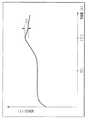
従来の一般的なデジタルカメラに適用される二次電池64としては、例えばニッケル水素電池等が適用されるが普通である。このニッケル水素電池は、急速充電動作を施した場合に、その充電量が100%(満充電状態)に達した時点で電圧がわずかに降下する傾向があることは周知である(図21参照)。
【0325】
したがって、本実施形態においては、図21に示すように二次電池64の満充電後の電圧降下の所定量をマイナス デルタ ヴイ(−ΔV)と規定し、当該二次電池64に対する充電動作を行なっているときにはその電圧を周期的に測定し、所定量の電圧降下(−ΔV)を検出した時点で二次電池64は満充電状態になったものと判断し、実行中の充電動作を停止すればよいわけである。
【0326】
つまり、ステップS305において、サブコントローラ63は所定量の電圧降下(−ΔV)が検出されたか否かの確認を行なう。ここで、電圧降下(−ΔV)が検出された場合にはステップS307の処理に進む。
【0327】
続いて、ステップS307において、サブコントローラ63は定電流回路66の充電動作を停止させる。その後、ステップS308の処理に進む。
【0328】
ステップS308において、サブコントローラ63は、充電動作中フラグをリセット(初期化=「0」にする)し、さらに充電完了フラグを設定する(「1」)する。その後、ステップS302の処理に戻り、以降の処理を繰り返す。
【0329】
一方、上述のステップS305の処理において、電圧降下(−ΔV)が検出されなかった場合にはステップS306の処理に進み、このステップS306において、サブコントローラ63は充電タイマーのカウント動作が終了しているか否かの確認を行なう。ここで、当該カウント動作の終了が確認された場合には、強制的に充電動作を停止させるために、上述のステップS307の処理に進む。また、当該カウント動作の終了が確認されていない場合、即ち計時動作中には上述のステップS302の処理に戻り、以降の処理を繰り返す。
【0330】
例えば、二次電池64の電圧降下(−ΔV)の検出に失敗したような場合には、充電動作が継続されてしまうので過充電状態になってしまうことにもなりかねない。そこで、二次電池64に対する過充電を回避するために、上述のステップ305の処理を設けている。
【0331】
上述のステップS309の処理において、DSCコントローラ13からの通信要求が電池残量情報以外の通信要求である場合に図20のステップS315の処理に移行すると、このステップS315において、サブコントローラ63はDSCコントローラ13からの通信要求が充電動作開始要求であるか否かの確認を行なう。ここで、充電動作開始の通信要求であることが確認された場合には、次のステップS316の処理に進む。また充電動作開始の通信要求ではない場合には、ステップS320の処理に進む。なお、ここでサブコントローラ63に対してなされるDSCコントローラ13からの充電動作開始の通信要求は、上述のステップS7(図3)の処理で実行されるものである。
【0332】
続いてステップS316において、サブコントローラ63は現時点における二次電池64の残容量値と定電流回路66の出力電流値に基づいて満充電状態になるまでの充電時間(#Tcharge)の推測値を算出する。その後、ステップS317の処理に進む。
【0333】
ステップS317において、サブコントローラ63は自己の内部タイマーを充電タイマーに割り付けて、この充電タイマーに「#Tcharge」へ設定した後、計時動作を開始する。その後、ステップS318の処理に進む。
【0334】
ステップS318において、サブコントローラ63は定電流回路66の動作を開始させる。その後、ステップS319の処理に進む。
【0335】
ステップS319において、サブコントローラ63は充電動作中フラグをセット(「1」)すると共に、充電動作完了フラグをリセット(初期化=「0」)する。その後、図19のステップS302の処理に戻り、以降の処理を繰り返す。
【0336】
上述のステップS315の処理において、DSCコントローラ13からの通信要求が充電動作開始の要求以外の通信要求である場合にステップS320の処理に移行すると、このステップS320において、サブコントローラ63はDSCコントローラ13からの通信要求が充電動作一時停止指令の要求であるか否かの確認を行なう。ここで、充電動作一時停止指令の通信要求であることが確認された場合には、次のステップS321の処理に進む。また充電動作一時停止指令以外の通信要求である場合には、ステップS324の処理に進む。なお、ここでサブコントローラ63に対してなされるDSCコントローラ13からの充電動作一時停止の通信要求は、上述のステップS108(図15)・S128(図16)・S148(図17)・S168(図18)の処理で実行されるものである。
【0337】
ステップS321において、サブコントローラ63は充電タイマーの計時(カウント)動作を一時的に停止させる。その後、ステップS322の処理に進む。
【0338】
ステップS322において、サブコントローラ63は定電流回路66の動作を停止させる。その後、ステップS323の処理に進む。
【0339】
ステップS323においては、サブコントローラ63は充電動作中フラグをリセット(初期化=「0」)する。その後、図19のステップS302の処理に戻り、以降の処理を繰り返す。
【0340】
上述のステップS320の処理において、DSCコントローラ13からの通信要求が充電動作一時停止要求以外の通信要求である場合にステップS324の処理に移行すると、このステップS324において、サブコントローラ63はDSCコントローラ13からの通信要求が充電動作の再開指令の要求であるか否かの確認を行なう。ここで、充電動作再開指令の通信要求であることが確認された場合には、次のステップS325の処理に進む。また充電動作再開指令以外の通信要求である場合には、ステップS328の処理に進む。なお、ここでサブコントローラ63に対してなされるDSCコントローラ13からの充電動作再開の通信要求は、上述のステップS113(図15)・S133(図16)・S153(図17)・S173(図18)の処理で実行されるものである。
【0341】
ステップS325において、サブコントローラ63は充電タイマーの計時(カウント)動作を再開させる。その後、ステップS326の処理に進む。
【0342】
ステップS326において、サブコントローラ63は定電流回路66の充電動作を再開させる。その後、ステップS327の処理に進む。
【0343】
ステップS327において、サブコントローラ63は充電動作中フラグをセットセット(「1」)する。その後、図19のステップS302の処理に戻り、以降の処理を繰り返す。
【0344】
上述のステップS324の処理において、DSCコントローラ13からの通信要求が充電動作再開要求以外の通信要求である場合にステップS328の処理に移行すると、このステップS328において、サブコントローラ63はDSCコントローラ13からの通信要求が充電情報の送信要求であるか否かの確認を行なう。ここで、DSCコントローラ13からの通信要求が充電情報の送信要求以外の通信要求である場合にはステップS334の処理に進み、このステップS334において、その他の通信要求に応じた処理を実行する。その後、上述のステップS302の処理に戻り(図20・図19の符号J参照)、以降の処理を繰り返す。
【0345】
また、上述のステップS328において、DSCコントローラ13からの通信要求が充電情報の送信要求の通信要求であることが確認された場合には、次のステップS329の処理に進む。なお、ここでサブコントローラ63に対してなされるDSCコントローラ13からの充電動作再開の通信要求は、上述のステップS14(図3)の処理で実行されるものである。
【0346】
ステップS329において、サブコントローラ63は充電完了フラグに基づいて充電動作が終了しているか否かの確認を行なう。ここで、充電完了フラグがセットされているとき(「1」に設定されている)には充電動作が完了(終了)しているので、次のステップS332の処理に進む。
【0347】
ステップS332において、サブコントローラ63はDSCコントローラ13に対して二次電池64の充電動作が終了した旨を告知する。その後、上述のステップS302の処理に戻り(図20・図19の符号J参照)、以降の処理を繰り返す。
【0348】
一方、上述のステップS329において、充電完了フラグがセットされていないとき(「0」に設定されている)には充電動作の実行中であるので、次のステップS330の処理に進む。
【0349】
ステップS330において、サブコントローラ63は充電動作を開始した時点での電池残容量や定電流回路66の出力電流・充電タイマーの計時(カウント)値等の情報に基づいて現在の電池容量値と満充電までの推定充電時間とを算出する。その後、ステップS331の処理に進む。
【0350】
ステップS331において。上述のステップS330で算出した各値(電池容量値と推定充電時間等の情報をDSCコントローラ13に向けて送信する。その後、図19のステップS302の処理に戻り、以降の処理を繰り返す。
【0351】
なお、上述のステップS331において、サブコントローラ63によって算出された各情報(例えば電池容量値と予測充電時間)は、これらの値に1以上の係数を乗じた後の演算結果をDSCコントローラ13の側に向けて送信するようにしてもよい。
【0352】
これを受けてDSCコントローラ13は、上述したようにサブコントローラ63からの送信してくる情報に基づいて所定の充電情報を液晶モニタ15を用いて表示する。
【0353】
なお、液晶モニタ15に表示される充電情報は充電動作中における単なる目安となるものであるので、当該液晶モニタ15に表示される予測充電時間よりも早期に充電動作が終了したとしてもなんら問題ではない。
【0354】
以上説明したように上記一実施形態によれば、デジタルカメラ10とこのデジタルカメラ10によって撮影され取得された画像データに基づく画像をプリントするプリンタ60とからなるプリントシステムにおいて、デジタルカメラ10に適用される二次電池64に対してプリンタ60の側から給電し、これを充電し得るように構成すると共に、当該二次電池64の状態をデジタルカメラ10の側の液晶モニタ15(表示手段)の表示部を用いて表示確認し得るように構成したので、操作性及び使用感の向上に寄与することができる。
【0355】
また、この場合において、液晶モニタ15の表示部に表示する表示形態をデジタルカメラ10及びプリンタ60の動作状態によって適宜適切な形式で表示するように工夫したので、操作性及び使用感のより一層の向上に寄与することができる。
【0356】
【発明の効果】
以上述べたように本発明によれば、デジタルカメラとこのデジタルカメラから受信した画像データに基づいて画像をプリントするプリンタとからなるプリントシステムにおいて、デジタルカメラに適用される二次電池に対してプリンタ側から給電し充電し得るように構成すると共に、この二次電池の状態をデジタルカメラ側の表示手段を用いて表示確認し得るようにし、さらにその際の表示形態やその選択手段及び表示変更手段等を工夫して、使用者の操作性及び使用感の向上を実現し得るプリントシステムを提供することができる。
【図面の簡単な説明】
【図1】本発明の一実施形態のプリントシステムを構成するデジタルカメラ(画像入力装置)とプリンタ(画像形成装置)とのそれぞれの内部構成の概略を示すブロック構成図。
【図2】図1のプリントシステムにおけるデジタルカメラとプリンタとが接続する接続部位の構成及び両者の各電源回路の構成の内部概略を示すブロック構成図。
【図3】図1のプリントシステムにおけるデジタルカメラとプリンタとが接続された状態にあるときの当該プリントシステムにおけるメインルーチンの一部を示すフローチャート。
【図4】図1のプリントシステムにおけるデジタルカメラとプリンタとが接続された状態にあるときの当該プリントシステムにおけるメインルーチンの一部を示すフローチャート。
【図5】図1のプリントシステムにおけるデジタルカメラとプリンタとが接続された状態にあるときの当該プリントシステムにおけるメインルーチンの一部を示すフローチャート。
【図6】図1のプリントシステムにおけるデジタルカメラの二次電池の充電状態に関する情報等の一つの表示例を示す図。
【図7】図1のプリントシステムにおけるデジタルカメラの二次電池の充電状態に関する情報等の別の表示形態の一例を示す図。
【図8】図1のプリントシステムにおけるデジタルカメラの二次電池の充電状態に関する情報等の他の表示形態を示す図。
【図9】図1のプリントシステムにおけるデジタルカメラによって取得される画像データに基づく画像及びその附帯情報の表示例を示す図。
【図10】図1のプリントシステムにおけるデジタルカメラの二次電池の充電状態に関する情報等のさらに別の表示形態を示す図。
【図11】図1のプリントシステムにおけるデジタルカメラの二次電池の充電状態に関する情報等のさらに異なる別の表示形態を示す図。
【図12】図1のプリントシステムにおけるデジタルカメラによって取得される画像データに基づく画像及びその附帯情報の別の表示例を示す図。
【図13】図1のプリントシステムにおけるデジタルカメラの二次電池の充電状態に関する情報等のさらに異なる他の表示形態を示す図。
【図14】図1のプリントシステムの一部を構成するデジタルカメラが単独でカメラとして動作する際のサブルーチン「DSCメイン」を示すフローチャート。
【図15】図1のプリントシステムによって実行される印刷処理のサブルーチンの一部を示すフローチャート。
【図16】図1のプリントシステムによって実行される印刷処理のサブルーチンの一部を示すフローチャート。
【図17】図1のプリントシステムによって実行される印刷処理のサブルーチンの一部を示すフローチャート。
【図18】図1のプリントシステムによって実行される印刷処理のサブルーチンの一部を示すフローチャート。
【図19】図1のプリントシステムにおけるデジタルカメラのサブコントローラの一部の作用を示すフローチャート。
【図20】図1のプリントシステムにおけるデジタルカメラのサブコントローラの一部の作用を示すフローチャート。
【図21】従来の一般的なデジタルカメラに適用される二次電池における充電量と電池電圧の関係を示す線図。
【符号の説明】
10……デジタルカメラ(画像入力装置)
11……撮影光学系
12……撮像ユニット
13……DSCコントローラ(制御手段)
13a……CCDインターフェイス回路
13b……メモリインターフェイス回路
13c……ビデオエンコーダ回路
13d……画像サイズ変換回路
13e……画像圧縮伸張回路
13f……RISCコントローラ
14……カメラ操作スイッチ
15……液晶モニタ
16……SDRAM
17……フラッシュロム
18……記録メディア
19……USBホストコントローラ
20……外部バスライン
21……カメラ電源回路
22……マイクロコンピュータ(制御手段)
23……外部バスライン
25……サーマルヘッド制御回路
26……ファン
27……ファンモータ
28……ファンモータ駆動回路
29……リボンケース検出スイッチ
30……リボンモータ
31……リボンモータ駆動回路
32……インクリボンケース
32……リボンケース
33……インクリボン
34……円盤
35……リボン移動検出センサ
36……リボン位置検出センサ
37……温度センサ
38……サーマルヘッド
39……ヘッドアーム
40……カム
41……ヘッド位置制御モータ
42……ヘッドモータ駆動回路
43……ヘッド位置センサ
44……用紙トレイ検出スイッチ
45……用紙トレイ
46……プリント用紙
47……グリップローラ
48……ピンチローラ
49……搬送モータ
50……搬送モータ駆動回路
51……用紙位置センサ
52……プラテンローラ
53……不揮発性メモリ
54……プリンタ操作スイッチ
55……プリンタ電源回路
56……電源端子
57……接続端子(カメラ側)
58……接続端子(プリンタ側)
59 ACアダプタ
60……プリンタ(画像形成装置)
61……PCV
62……発音回路
63……サブコントローラ
63a……ADコンバータ
64……二次電池
65A……DCDCコンバータ(デジタルカメラ側)
65B……DCDCコンバータ(プリンタ側)
66……定電流回路
67……温度検出センサー[0001]
BACKGROUND OF THE INVENTION
BACKGROUND OF THE
[0002]
[Prior art]
Based on a digital camera capable of recording electronic image data acquired by photoelectrically converting an optical image as digital data, and digital data photographed and recorded by an image input device (hereinafter referred to as a digital camera) such as a digital still camera. Conventionally, various proposals have been made on a printing system including an image printing apparatus (hereinafter referred to as a printer) such as a printer capable of printing an image on a printing paper.
[0003]
The present applicant has previously proposed a printing system including a digital camera and a printer for printing an image photographed using the digital camera, for example, in Japanese Patent Laid-Open No. 10-2000085. The means disclosed in Japanese Patent Laid-Open No. 10-200850 allows an image based on image data selected as a print target to be confirmed by displaying it using a display unit on the digital camera side, and thus confirmed. The image data representing the image is transmitted to the printer side. With such a configuration, it is possible to easily and reliably perform selection and confirmation of an image to be printed and printing of an image intended by the user.
[0004]
In such a system, when a plurality of print target images are designated, the voltage of a secondary battery that is a power source for operating the system in the middle of executing the designated plural print operations There is a possibility that so-called battery exhaustion may occur due to a decrease in battery life. In this case, after replacing the battery, the user needs to restart the printing operation stopped halfway and perform a setting operation for performing printing for an unprinted state again. Such a resetting operation is troublesome for the user and becomes a factor that hinders the operability of the printing system.
[0005]
It can be considered that the fact that the system power is turned off due to the so-called “battery exhaustion” as described above, etc., occurs in the past immediately before or after the printing operation that requires relatively large power. . In this case, when the power is turned off due to so-called battery exhaustion or the like, information regarding various printing conditions set in advance by the user, such as trimming information and date information, is shut off. It will disappear at the same time. That is, even if the user has set detailed information regarding print conditions and the like, all of the settings are invalidated, which not only hinders operability but also a very serious problem.
[0006]
Therefore, the applicant of the present invention has previously proposed a means for coping with the above-described problem by Japanese Patent Application Laid-Open No. 2001-80174. The means disclosed in Japanese Patent Laid-Open No. 2001-80174 is a battery that is necessary for determining whether or not a digital camera is out of battery (hereinafter also referred to as a low battery state or a low battery state). A reduced power source detection circuit for detecting the capacity is provided, and when it is detected that the remaining capacity of the battery is below a predetermined level (power reduction level) required for continuing the processing (detected as being in a power reduction state) If this happens, the printing process that is being executed at that time is stopped and the digital camera side is switched off so that an unexpected situation can be avoided. It is.
[0007]
Further, the present applicant has previously proposed a technique for charging a digital camera with a dedicated charging device in Japanese Patent Application Laid-Open No. 2001-86651. With the means disclosed in Japanese Patent Laid-Open No. 2001-86651, the camera can be operated even when the voltage of the secondary battery applied to the digital camera is lowered and the camera cannot be operated. Improving usage efficiency by enabling operations such as outputting recorded image data to the outside as soon as the camera becomes inoperable without waiting for the secondary battery to be charged until it reaches the specified voltage level. The charging device which can be made to realize is realized. In other words, in the charging device, when the digital camera is coupled, the charging device performs the charging operation of the secondary battery of the camera, and at the same time, by directly supplying power to the digital camera, the digital camera side Are configured to enable functions such as outputting recorded image data.
[0008]
Furthermore, the present applicant has previously proposed Japanese Patent Application Laid-Open No. 2001-66658 regarding display means for displaying various information in a digital camera, for example, information related to charging, information related to photographing, and the like. The means disclosed in Japanese Patent Laid-Open No. 2001-66658 is a system composed of a digital camera and a charger, and includes a first display means for displaying information related to a charging state of the digital camera, Two display means including a second display means for displaying information related to photographing are provided, and the first display means and the second display means are provided in the same exterior window on the digital camera side. Thus, the user can clearly display that the battery is being charged when desired by only operating the digital camera without providing any display means on the charger side. Therefore, according to this, it is possible to prevent misrecognition of the charging operation and contribute to improvement in operability.
[0009]
[Patent Document 1]
Japanese Patent Laid-Open No. 10-200850
[0010]
[Patent Document 2]
JP 2001-80174 A
[0011]
[Patent Document 3]
JP 2001-86651 A
[0012]
[Patent Document 4]
JP 2001-66658 A
[0013]
[Problems to be solved by the invention]
By the way, in a printing system including a digital camera and a printer that prints an image based on image data captured and acquired by the digital camera, the printer side supplies power to a rechargeable battery (secondary battery) applied to the digital camera. However, it is convenient if it is configured so that it can be charged and the state of the secondary battery can be confirmed using display means on the digital camera side.
[0014]
However, a specific proposal has not yet been made for the print system configured as described above. Furthermore, no specific proposals have been made for the display form, selection means, display form changing means, and the like at that time.
[0015]
The present invention has been made in view of the above-described points, and an object thereof is a printing system including a digital camera and a printer that prints an image based on image data received from the digital camera. The secondary battery applied to the digital camera can be charged by charging from the printer side, and the state of the secondary battery can be confirmed using the display means on the digital camera side. The present invention is to provide a print system that can improve the user's operability and feeling of use by devising the display form, selection means, display change means, and the like at that time.
[0016]
[Means for Solving the Problems]
In order to achieve the above object, a printing system according to a first aspect of the present invention is a printing system in which a digital camera provided with control means for controlling operations and a printer are functionally combined, The digital camera is configured to be able to supply data representing an image to be printed by the printer to the printer under the control of the control means of the digital camera. Further, the digital camera supplies power to the secondary battery as its power source from the printer side. The printer is configured to display the status of each corresponding function including the status of the secondary battery on a predetermined display unit, and the printer is controlled by its control means. Thus, it is configured so that an image can be printed based on image data supplied from the digital camera side, and further, power is supplied to the digital camera side. Is configured so as to charge the secondary battery, and said digital camera,Under the control of the control means, the display of the image to be printed or the candidate is displayed as a relatively large main display on the predetermined display unit, and the display indicating the state of the secondary battery is relatively displayed. A first display format that is displayed together with the main display as a small subordinate display, and a display that indicates the state of the secondary battery as a relatively large main display and is a target or candidate for printing. The second display format that displays the image display together with the main display as a relatively small sub-display can be arbitrarily selected by the operator. It is configured as described above.
[0017]
In addition, the second departureThe printing system according to Ming is a printing system in which a digital camera provided with control means for controlling operations and a printer are functionally combined, and the digital camera includes its own control means and the above-described control means. An image data transmission unit for supplying image data representing an image to be printed by the printer out of the image data acquired by the imaging unit under control by linking with the control unit on the printer side, and a self-power source A charging circuit for charging the applied secondary battery by receiving power from the printer side, and a battery for detecting and managing the state of the secondary battery and supplying the detection data to the control means of the digital camera Under the control by the control means on the digital camera side, the state of each corresponding function including the state of the management circuit unit and the secondary battery, A display unit for displaying on a fixed display unit, and an operation unit for receiving an operation by an operator. The printer includes its own control unit and a control unit on the digital camera side. An image data receiving means for receiving the image data supplied from the digital camera side under the control of the linkage, and a printing means configured to execute printing of the image based on the received image data; A power supply circuit configured to supply power to the digital camera to charge the secondary battery, and the digital camera is under the control of its own control means, A display of an image to be printed or a candidate thereof is displayed on the display unit as a relatively large main display, and a display indicating the state of the secondary battery is relatively displayed. A first display format that is displayed together with the main display as a secondary display, and a display indicating the state of the secondary battery as a relatively large main display and an image to be printed or a candidate thereof. A second display format that displays the display as a relatively small sub-display together with the main display can be selected according to the operation of the operation unit by the operator. It is configured as described above.
[0018]
And the third departureThe digital camera according to Ming is a digital camera suitable for a printing system configured by functionally combining a digital camera provided with control means for controlling operations and a printer, and corresponding to a subject. Image data representing an image to be printed by the printer out of the image data acquired by the imaging means under the control of the imaging means for obtaining data and the control means of the self and the control means on the printer side. Image data transmission means for supplying to the printer, a charging circuit for charging a secondary battery applied as its own power source by receiving power from the printer side, and detecting and managing the state of the secondary battery And a battery management circuit unit for supplying data by the detection to the control means of itself, and states of the corresponding functions including the state of the secondary battery. A display unit for displaying on a predetermined display unit under the control of the control unit; and an operation unit for receiving an operation by an operator; the control unit is configured to display the display unit under the control of the control unit. The display of the image to be printed or the candidate is displayed as a relatively large main display, and the display indicating the state of the secondary battery is displayed together with the main display as a relatively small secondary display. 1 and the display indicating the state of the secondary battery are displayed as a relatively large main display, and the display of an image to be printed or a candidate thereof is displayed as a relatively small secondary display. The second display format to be displayed together with the display can be selected according to the operation of the operation unit by the operator. And features.
[0046]
DETAILED DESCRIPTION OF THE INVENTION
The present invention will be described below with reference to the illustrated embodiments.
FIG. 1 is a block configuration diagram showing an outline of internal configurations of a digital camera (image input apparatus) and a printer (image forming apparatus) constituting a print system according to an embodiment of the present invention.
[0047]
As shown in FIG. 1, the printing system of this embodiment includes two devices, an image input device (hereinafter referred to as a digital camera) 10 such as a digital camera and an image forming device (hereinafter referred to as a printer) 60 such as a thermal sublimation printer. The two are configured to be electrically connected to each other by a predetermined communication means conforming to the USB (Universal Serial Bus) standard which is one of serial interface standards. The digital camera 10 and the printer 60 are respectively provided with control means (
[0048]
In other words, the printing system according to the present embodiment is configured by functionally coupling the digital camera 10 and the printer 60 each having control means (13, 22) for controlling operations.
[0049]
First, main components constituting the inside of the digital camera 10 will be described with reference to FIG.
A digital camera 10 that constitutes a part of the printing system of the present embodiment includes a photographing optical system 11 that includes a plurality of optical elements and the like to collect a light beam from a subject to form an optical subject image, and a photoelectric conversion element. In order to achieve a function as an image input device and an image pickup unit 12 (an image pickup device such as a CCD (Charge-Coupled Device) sensor) or a drive circuit thereof, an overall control of the operation of the digital camera 10 is performed. Control means, for example, a DSC (Digital Still Camera)
[0050]
The
[0051]
The
[0052]
In this case, the
[0053]
The encoding process performed by the image compression /
[0054]
The generated JPEG image data is not recorded in a predetermined area of the
[0055]
In addition, the decoding process performed by the image compression /
[0056]
As described above, the
[0057]
The
[0058]
The
[0059]
In a state where the digital camera 10 and the printer 60 are connected by the
[0060]
For this purpose, the
[0061]
In the present embodiment, as shown in FIG. 1, an example in which the
[0062]
The camera
[0063]
When the digital camera 10 and the printer 60 are connected by the
[0064]
That is, when the printing system of the present embodiment operates with the digital camera 10 and the printer 60 connected, the power supplied from the printer
[0065]
Further, when the digital camera 10 and the printer 60 are connected by the
[0066]
Next, main components constituting the inside of the printer 60 will be described with reference to FIG.
[0067]
A printer 60 constituting a part of the print system of the present embodiment is connected to the above-described
[0068]
The
[0069]
Further, the
[0070]
Here, the
[0071]
The operation members that can operate the
[0072]
That is, when the user operates a predetermined operation member of the printer 60, a corresponding instruction signal is generated from the
[0073]
Further, the
[0074]
Further, the
[0075]
The
[0076]
That is, the
[0077]
The
[0078]
Therefore, the
[0079]
The transport motor 49 takes out (carrying out) the
[0080]
Note that the printing paper conveyance means in the printer 60 is constituted by components such as a conveyance motor 49, a conveyance
[0081]
The
[0082]
The ink ribbon 33 housed in the ribbon case 32 has a transfer film and a protective layer coated with dyes (Y (yellow), M (magenta), and C (cyan)) that are thermally transferred to the
[0083]
A mark of a predetermined form for detection is formed on each film (Y, M, C, protective layer) in the ink ribbon 33. The ribbon position detection sensor 36 detects the position of each film of the ink ribbon 33 by detecting this mark.
[0084]
The printer
[0085]
The printer
[0086]
As will be described later, the
[0087]
The
[0088]
Next, the configuration of the connection portion where the digital camera and the printer are connected in the print system of the present embodiment and the configuration of the power supply circuit provided in the digital camera and the printer will be described in detail below with reference to FIG.
[0089]
FIG. 2 is a block configuration diagram showing an internal outline of the configuration of the connection portion where the digital camera and the printer are connected and the configuration of each power supply circuit (camera
[0090]
In the printing system of the present embodiment, the connection means for connecting the digital camera 10 and the printer 60 constituting this is provided on the
[0091]
Six signal lines Vbus, D +, D-, GND, CHG, and PGND are arranged inside the
[0092]
More specifically, the CHG is a line for supplying operating power for operating the digital camera 10 and power for charging the
[0093]
The normal USB standard is configured such that power can be supplied from the host side to the target device side by using the Vbus line as the second power supply line. In contrast, the print system according to the present embodiment is configured to supply power from the printer 60 serving as a target device toward the digital camera 10 serving as a host. The printer 60 is configured to be able to operate with power supplied from its own power source. For this reason, this printing system is configured such that Vbus is not used as a power supply line but can be used to configure a signal communication interface.
[0094]
On the digital camera 10 side, the
[0095]
The resistor R04 is a dummy load resistor necessary for measuring the battery voltage, and a current can be passed from the
[0096]
The IO port P_ContR of the sub-controller 63 is connected to Q01, and the on / off control of Q01 can be performed by the IO port P_ContR. The resistors R6 and R5 are resistors for converting the voltage of the
[0097]
A
[0098]
In a state where the digital camera 10 and the printer 60 are connected, the power input via the CHG lines of the
[0099]
The DC /
[0100]
Further, the
[0101]
The signal lines D + and D− of the
[0102]
The output of CHG is divided by resistors R02 and R03 and then input to P_DetChg, which is an IO port of the
[0103]
On the other hand, the printer power supply circuit 55 (see FIG. 1) on the printer 60 side includes a DC /
[0104]
In this case, a part of the line of the DC /
[0105]
The data transfer rate can be notified by pulling up either one of the operation signal lines D + and D-. In this embodiment, communication is performed at full speed (12 Mbps). ing. Therefore, the signal line D + is pulled up. For this purpose, the transistor Q11 and the resistor R12 are connected to the D + side.
[0106]
The transistor Q11 is connected to the IO port P_PullD + of the
[0107]
When establishing (opening) the USB communication line, the
[0108]
The operation of the printing system of the present embodiment configured as described above will be described below.
3, 4, and 5 show the operation of the printing system of the present embodiment, and are flowcharts of a main routine in the printing system when the digital camera and the printer are connected.
[0109]
3 to 5, the operation process of the DSC controller (13) on the digital camera side and the operation process of the microcomputer (22) on the printer side are shown side by side, and the state when operating in communication with each other or connected to each other Is shown so that can be easily understood.
[0110]
First, the main routine of the print system according to the present embodiment will be described below with reference to FIGS.
[0111]
The main routine of the printing system starts a series of processes when the
[0112]
In this case, when the digital camera 10 and the printer 60 are connected, a predetermined operating member (not shown; printer-side main power supply) for switching the on / off state of the printer
[0113]
On the other hand, the camera
[0114]
When the camera
[0115]
On the other hand, when the digital camera 10 and the printer 60 are connected, the printer
[0116]
In step S2, the
[0117]
That is, in this step S2, the
[0118]
If the
[0119]
If it is determined in step S2 that the digital camera 10 and the printer 60 are in a connected state, a printer system in which both operate in cooperation as described above is configured. For that purpose, it is necessary to establish (open) a communication line between them.
[0120]
In step S3, the
[0121]
On the other hand, in response to the predetermined instruction signal transmitted from the
[0122]
Next, in step S4, the
[0123]
In this case, even when the
[0124]
In step S <b> 5, the
[0125]
In step S6, the
[0126]
On the other hand, when the
[0127]
In step S <b> 8, the
[0128]
A display example of information relating to the state of charge of the
[0129]
First, when the information acquired from the sub-controller 63 indicates that the battery capacity is already fully charged (100% charged state), for example, a display as shown in FIG. 6 is displayed on the display unit of the
[0130]
In the display form shown in FIG. 6, the
[0131]
On the other hand, when the information acquired from the sub-controller 63 indicates that the battery capacity is less than 100%, for example, a display as shown in FIG. 7 is displayed on the display unit of the
[0132]
In the display form shown in FIG. 7, as a case where the battery capacity is less than 100%, for example, a case where the battery capacity is 40% of the fully charged state is shown. Is in a form according to FIG. That is, in addition to the display form of the character string representing the details of the
[0133]
On the other hand, when it is determined from the information acquired from the sub-controller 63 that the
[0134]
In the display form shown in FIG. 8, a warning that the charging operation cannot be executed because the
[0135]
After the process of step S8 described above, that is, the predetermined display process by the
[0136]
Here, the display state data is data indicating the display state of the
[0137]
When the display state data is “# 0”, it indicates that the liquid crystal monitor 15 is not performing a display operation, that is, no display is performed. This state is switched, for example, when no operation is performed for a predetermined time when the digital camera 10 is in a power-on state.
[0138]
Further, when the display state data is “# 1”, it is indicated that predetermined information regarding the
[0139]
When the display state data is “# 2”, it is indicated that an image based on predetermined image data selected by the user is displayed on the
[0140]
Next, in step S10, the
[0141]
Here, for example, when the user operates a predetermined operation member, the timing operation is interrupted by an interrupt instruction signal from the operation member, and the display on the liquid crystal monitor 15 is stopped. Further, when the user does not operate the predetermined operation member until the predetermined time elapses, that is, the count value set in the display timer without generation of the predetermined interrupt signal is “# Tdata1”. The display on the liquid crystal monitor 15 stops at that point.
[0142]
In other words, the first time set by the above “# Tdata1” is anything for the digital camera 10 when the display indicating the state of the
[0143]
In this way, after the display on the liquid crystal monitor 15 is stopped, the process proceeds to the next step S11.
[0144]
In step S <b> 11, the
[0145]
In this case, when the
[0146]
Here, the signal transmission / reception operation performed between the
[0147]
As described above, the
[0148]
In step S <b> 12, the
[0149]
In step S13, the
[0150]
If it is confirmed that the charging operation flag is “1”, it is determined that the charging operation is being performed, and the process proceeds to the next step S14. In this step S14, the DSC controller 13 A command for requesting the sub-controller 63 to transmit the charging information is issued. In response to the request command, the
[0151]
Thus, during the execution of the charging operation, the process of step S14 described above is periodically executed, so that the
[0152]
Subsequently, in step S15, the
[0153]
In addition, when the digital camera 10 operates in cooperation with the printer 60, the zoom switch displays an image based on the image data recorded on the
[0154]
In step S15, when the instruction signal from the zoom switch (ZoomSW) is confirmed and it is determined that the predetermined operation member has been operated by the user, the process proceeds to step S16. On the other hand, if the instruction signal from the zoom switch (ZoomSW) is not confirmed and it is determined that the predetermined operation is not performed, the process proceeds to step S19.
[0155]
In step S <b> 16, the
[0156]
In step S <b> 17, the
[0157]
In step S18, the
[0158]
In step S30, the
[0159]
In step S31, the
[0160]
The state of the liquid crystal monitor 15 before the new image is displayed on the liquid crystal monitor 15 in the above-described step S30 is, for example,
A state where nothing is displayed on the liquid crystal monitor 15 (display state data “# 0”),
A state in which the
A state in which an image selected by the user is displayed on the liquid crystal monitor 15 (display state data “# 2”);
Etc. In the above-described step S30, a new selected image is displayed on the liquid crystal monitor 15 regardless of the previous state of the
[0161]
FIG. 9 shows one form of image display displayed on the liquid crystal monitor 15 when the process of step S30 described above is executed.
[0162]
As shown in FIG. 9, in this display mode, an image corresponding to the image data selected using the entire display area of the liquid crystal monitor 15 is displayed, and the image incidental included in the image data is displayed at a predetermined position in the screen. Information, for example, various information such as a frame number and date data is displayed by a character string or the like. In this case, the image supplementary information is displayed superimposed on the image using, for example, an OSD (On-Screen Display) function.
[0163]
Subsequently, in step S32, the
[0164]
Here, when the user does not operate the predetermined operation member until the predetermined time set in the display timer elapses, that is, the count value set in the display timer without generation of the predetermined interrupt signal. When “# Tdata2” is reached, the display of the liquid crystal monitor 15 is stopped at that time.
[0165]
That is, the second time set by the above “# Tdata2” is when the image to be printed or the candidate image is displayed on the display unit of the liquid crystal monitor 15 of the digital camera 10. This is a predetermined specified time as a condition for turning off the display when no operation is performed on the digital camera 10.
[0166]
When the display on the liquid crystal monitor 15 is stopped in this way, the process returns to the above-described step S11 and the subsequent processes are repeated.
[0167]
On the other hand, if the instruction signal from the zoom switch is not confirmed in the process of step S15 and the process proceeds to the process of step S19, the
[0168]
When it is confirmed that the instruction signal from the print permission switch is generated in the process of step S19 described above and the process proceeds to step S20, the
[0169]
On the other hand, if it is confirmed in step S20 described above that the image data desired to be printed has been selected, the process proceeds to the next step S21.
[0170]
In step S21, the
[0171]
Then, when the process of step S22 ends, the process proceeds to the process of step S32 described above.
[0172]
On the other hand, if it is confirmed in the above-described step S21 that “# 2” is not set in the display state data, the execution of the printing operation is prohibited, and the process proceeds to the above-described step S30. Here, for example, when “# 0” is set in the display state data, no display is made on the
[0173]
When it is confirmed in the process of step S19 that the instruction signal from the print permission switch has not been generated, and in the process of step S20, it is confirmed that no image data has been selected. If the process proceeds to step S23 in FIG. 4, in step S23, the
[0174]
If it is confirmed that an instruction signal from the printer power switch is generated and it is determined that the printer power is on, the process proceeds to step S33 shown in FIG. If it is confirmed that the instruction signal from the printer power switch is not generated and it is determined that the printer power is off, the process proceeds to the next step S24.
[0175]
In step S24, the
[0176]
In step S25, the
[0177]
In step S <b> 26, the
[0178]
In step S27, the
[0179]
In this case, when the user performs an operation for turning off the power switch of the printer 60, that is, the power state of the printing system, the charging operation of the
[0180]
Therefore, a processing routine is provided in which the
[0181]
In step S28, the
[0182]
In step S29, the
[0183]
On the other hand, when it is determined that the printer power supply is in the on state in the process of step S23 described above and the process proceeds to the process of step S33 in FIG. Here, if the charging operation flag is “1”, it is determined that the charging operation has not yet ended (both incomplete state), and the process proceeds to step S34. If the charging operation flag is “0”, it is determined that the charging operation has ended, and the process proceeds to step S38.
[0184]
In step S34, the
[0185]
In step S35, the
[0186]
In step S36, the
[0187]
In step S <b> 37, the
[0188]
The charge end display executed in the process of step S36 described above is executed only for the set predetermined time, and the liquid crystal monitor 15 is stopped after the set time has elapsed. In addition, the charge end display is an operation having a higher priority than other display operations. Therefore, regardless of the display state of the
[0189]
On the other hand, if it is determined in the process of step S33 that the charging operation flag is “0” and it is determined that the charging operation has ended, and the process proceeds to step S38, the
[0190]
In step S39, the
[0191]
Next, in step S40, the
[0192]
If the display state data is not set to “# 1” in step S39, the process returns to the process in step S11 and the subsequent processes are repeated.
[0193]
On the other hand, when it is confirmed in the process of step S38 that the time counting operation by the display timer has ended and the process proceeds to the next step S41, the
[0194]
In step S46, the
[0195]
Next, in step S48, the
[0196]
In the above-described step S46, when the display state data is not set to “# 1”, it indicates that “# 0” is set for the display state data. Therefore, in this case, since the liquid crystal monitor 15 is not operating, the process returns to the above-described step S11 and the subsequent processes are repeated.
[0197]
In step S41, when it is confirmed that the display state data is set to "# 2" and the process proceeds to step S42, in step S42, the
[0198]
In step S47, as described above, the
[0199]
In other words, when the display state data is “# 2” (step S41) when the timing operation of the display timer is completed (step S38), the liquid crystal monitor 15 is based on predetermined image data selected by the user. Since an image is displayed (see FIG. 9), it is necessary to end this image display operation. The display on the liquid crystal monitor 15 after the end of the image display operation differs depending on whether or not the charging operation is being performed at that time. Therefore, the charging operation flag is checked in step S42 described above.
[0200]
As described above, when the charging operation flag is “1” in step S42, the process proceeds to step S43. In step S43, the
[0201]
In step S44, the
[0202]
In step S45, the
[0203]
If the charging operation flag is “0” in step S42, the process proceeds to step S47 as described above. In step S47, the
[0204]
A specific operation of the processes in steps S42 to S48 described above will be described as follows. That is, when it is confirmed that the charging operation is being performed in the process of step S42 (determination of the charging operation), an image display as shown in FIG. 9 is made on the liquid crystal monitor 15 and is set in advance. If the predetermined operation by the user is not performed during the predetermined time (# Tdata2), the display is switched to the charge level display shown in FIG. 11 after the predetermined time has elapsed (step S43).
[0205]
On the other hand, when it is confirmed that the charging operation is completed in the process of step S42 (determination of the charging operation), the image display as shown in FIG. 9 is made on the liquid crystal monitor 15 and is set in advance. If the user does not perform a predetermined operation during the predetermined time (# Tdata2), the display on the liquid crystal monitor 15 stops after the predetermined time has elapsed (step S47).
[0206]
As described above, the main routine is processed in this printing system.
[0207]
Incidentally, a relatively small liquid crystal monitor provided in a general digital camera is applied. For this reason, if a plurality of pieces of information are displayed on one screen, the display becomes extremely complicated, and the display form may be difficult for the user to view various types of information.
[0208]
Therefore, in the above-described embodiment, when an image is displayed on the
[0209]
Apart from such a display form, a display form that can display a plurality of information and the like on one screen while considering various types of information so as to be easily visible is also conceivable.
[0210]
For example, FIG. 12 is a diagram showing another example of image display performed using the liquid crystal monitor of the digital camera in the print system of the present embodiment.
[0211]
In the example shown in FIG. 12, when the image corresponding to the image data selected by the user is displayed on the liquid crystal monitor 15 of the digital camera 10, the charging operation to the
[0212]
That is, in the example shown in FIG. 12, the display of the image to be printed or the candidate is displayed as a relatively large main display on the display unit of the liquid crystal monitor 15 of the digital camera 10 and the state of the
[0213]
Specifically, as in the example shown in FIG. 9, the image corresponding to the image data selected by the user using the entire display area of the liquid crystal monitor 15 and the image supplementary information included in the image data are characters. In addition to this, information related to the charge level is further displayed as a character string in a part of the display area (area indicated by symbol A). In this case, the image supplementary information and the charge level information are displayed superimposed on the image using, for example, an OSD (On-Screen Display) function or the like.
[0214]
When an image is displayed using the
[0215]
In order to realize such a display form, it is easy to replace the process of displaying in the display form of FIG. 9 in step S30 of FIG. 3 with the process of displaying in the display form of FIG. Can be realized.
[0216]
FIG. 13 is a diagram illustrating another example of the charge level display performed using the liquid crystal monitor of the digital camera in the print system of the present embodiment.
[0217]
In the example illustrated in FIG. 13, when the liquid crystal monitor 15 of the digital camera 10 is displayed with a charge level indicating that the charging operation is being performed, if there is image data selected by the user, the liquid crystal monitor 15 An image is displayed using a part of the display area.
[0218]
That is, in the example shown in FIG. 13, a display indicating the state of the
[0219]
Specifically, similarly to the example shown in FIG. 11 described above, the charge level display is performed using the entire display area of the
[0220]
When the charge level display is performed using the
[0221]
In order to realize such a display form, instead of the process of displaying in the display form of FIG. 11 in steps S40 and S43 of FIG. 5, a process of displaying in the display form of FIG. Can be easily realized.
[0222]
By the way, in the above-described embodiment, two types of display forms (first display form and second display form) of image display and charge level display performed using the liquid crystal monitor 15 are performed at a predetermined display time. Based on this, switching control by the
[0223]
Specifically, for example, the release operation member of the digital camera 10 is an operation member that is operated when the shooting operation is performed when the operation mode can perform the shooting operation, but this is an operation that is not used during the printing operation. Usually it is a member. Therefore, it can be considered that this release operation member is used as a display switching operation member.
[0224]
That is, when the charge level is displayed on the
[0225]
In addition, when an image is displayed on the
[0226]
With such a configuration, two types of display modes of image display and charge level display can be switched alternately using the release operation member.
[0227]
Next, details of the subroutine “DSC main” when a digital camera that constitutes a part of the print system of the present embodiment operates alone as a camera will be described below with reference to FIG.
[0228]
While the digital camera 10 is in a power-on state and waiting for an instruction signal generated by the operation of the operation member by the user, the
[0229]
In step S <b> 52, the
[0230]
In step S53, the
[0231]
On the other hand, when the instruction signal from the
[0232]
First, in step S54, the
[0233]
In step S55, the
[0234]
If the instruction signal from the zoom switch (ZoomSW) is not confirmed in step S54 described above, the process proceeds to step S56.
[0235]
In step S56, the
[0236]
In step S57, the
[0237]
In step S58, the
[0238]
[0239]
In step S60, the
[0240]
In step S59, the
[0241]
In step S62, the
[0242]
On the other hand, if the instruction signal from the release switch is not confirmed in step S56, the process proceeds to step S63.
[0243]
In step S63, the
[0244]
If it is confirmed in step S63 that the camera power switch is turned off, the process proceeds to the next step S64. In step S64, the system down process of the digital camera 10 is performed. After the execution, a series of processing ends (END).
[0245]
Also, in the process of step S58 described above, when it is confirmed that the digital camera 10 is not in a photographing enabled state, the process proceeds to step S64 in order to execute the system down process of the digital camera 10. In step S64, the system down process of the digital camera 10 is executed, and then the series of processes is terminated (END).
[0246]
The system down process executed in step S64 described above includes, for example, a process for saving various data existing in the
[0247]
Next, details of a subroutine of print processing executed by the print system of the present embodiment will be described below with reference to FIGS. This printing process is a process corresponding to step S22 and step S94 in FIG.
[0248]
As described above, when the
[0249]
In step S101 in FIG. 15, the
[0250]
In step S102, the
[0251]
The YMC image data generated here is temporarily stored in an internal memory or the like of the DSC controller 13 (having a capacity capable of storing one screen of image data). When this color conversion process ends, the process proceeds to the next step S103.
[0252]
In step S <b> 103, the
[0253]
Here, the process of step S201 is executed on the printer 60 side. That is, in step S201, the
[0254]
Then, the
[0255]
At the same time, the
[0256]
Thus, when the paper feeding operation and the error detection operation on the printer 60 side are completed, the printer 60 enters a standby state.
[0257]
Note that an error detection operation is executed in the process of step S201 described above. However, if an error signal is detected here, the
[0258]
On the other hand, on the digital camera 10 side, in step S104, the
[0259]
In step S <b> 105, the
[0260]
Next, when the process proceeds to step S106 without detecting a paper feeding operation error, the subsequent processes, that is, the processes of steps S106 to S116 (on the
[0261]
That is, in step S106, the
[0262]
In response to this, the
[0263]
When the transfer process of the Y color image data for one screen is completed in step S106 described above and the process proceeds to the next step S107, in this step S107, the
[0264]
In step S <b> 108, the
[0265]
In general, in a thermal sublimation printer 60 as applied to the present embodiment, power is consumed most when the thermal head 38 is driven. When the printing operation is performed by driving the thermal head 38, even if the charging operation to the
[0266]
However, temporarily stopping the charging operation necessitates extension of the time required to complete the charging.
[0267]
In this case, in order to avoid extending the charging time, for example, a means of increasing the amount of power supplied from an AC adapter or the like and performing the charging operation concurrently can be considered. .
[0268]
However, in order to increase the power supply amount of the AC adapter for supplying power, there arises a problem that the volume of the AC adapter itself increases and its cost also increases.
[0269]
On the other hand, if the configuration is such that the charging operation is prohibited only when the thermal head 38 is driven without changing the AC adapter or the like, and the charging operation is continued during the other operations, the printing can be performed. Compared to the extension of the charging time that occurs when the charging operation is temporarily stopped during the operation, the extension time is slight.
[0270]
Therefore, the print system according to the present embodiment employs a configuration in which the charging operation is prohibited only while the thermal head 38 is being driven.
[0271]
In step S <b> 109, the
[0272]
In step S110, the
[0273]
When the
[0274]
First, the
[0275]
Next, the
[0276]
At the same time, the
[0277]
Further, in synchronism with the movement of the
[0278]
When the transfer operation of the Y color image data for one screen is completed, the paper transport operation of the
[0279]
When these series of operations are completed, the
[0280]
In parallel with the Y color image data transfer operation, the
[0281]
Here, for example, if any abnormality is detected by the
[0282]
For example, when a paper jam or the like is detected by the
[0283]
Further, for example, when ribbon breakage or the like is detected by the ribbon position detection sensor 36 during the winding operation of the ink ribbon 33, the operation is stopped and an end code including predetermined error information is transmitted to the
[0284]
On the other hand, as described above, when the
[0285]
If no error information is confirmed, it is determined that the printing operation for one screen of Y color image data has been completed without any problem, and the process proceeds to the next step S112.
[0286]
In step S112, the
[0287]
In step S113, the
[0288]
In step S <b> 114, the
[0289]
In step S115, the
[0290]
When the
[0291]
Even in this case, the
[0292]
Here, for example, when a paper jam or the like of the
[0293]
As described above, when the
[0294]
If the error information is not confirmed, the process proceeds to step S126 in FIG. 16 to execute the printing operation for the next M color image data for one screen (reference numeral F1 in FIGS. 15 and 16). .
[0295]
16, the
[0296]
Here, the processing routine of the M color image printing operation by the
[0297]
Similarly, the processing routine of the M color image printing operation by the
[0298]
Therefore, the detailed description of the M color image printing operation refers to the above-described Y color image printing operation, and the detailed description thereof is omitted.
[0299]
When the M image printing operation is completed without confirming the error information, the process proceeds to the process of step S146 in FIG. 17 to execute the printing operation for one screen of the next C color image data (FIGS. 16 and 17). F2).
[0300]
17, the
[0301]
Here, the processing routine of the C color image printing operation by the
[0302]
Similarly, the processing routine of the C color image printing operation by the
[0303]
Therefore, the detailed description of the C color image printing operation refers to the above-described Y color image or M color image printing operation, and the detailed description thereof is omitted.
[0304]
When the C image printing operation is completed without confirming the error information, the process proceeds to step S167 in FIG. 18 to execute the next overcoat process (reference F3 in FIGS. 17 and 18).
[0305]
This overcoat process is a process of applying a protective film layer that protects the printing surface of each color image of Y color, M color, and C color based on YMC image data, and is substantially the same as the above-described color image printing operation. Processing is executed.
[0306]
That is, first, in step S167, the
[0307]
Thereafter, the processing of steps S167 to S175 (
[0308]
The
[0309]
Note that the
Finally, in step S175, after receiving a predetermined end code, the
[0310]
Next, details of the subroutine regarding the operation of the sub-controller 63 in the print system of the present embodiment will be described below with reference to FIGS.
[0311]
The
[0312]
First, in step S301 shown in FIG. 19, the sub-controller 63 executes an initial setting operation at startup. In this startup initial setting operation, for example, initialization of a memory, an IO port, and the like is executed. Thereafter, the process proceeds to step S302.
[0313]
In step S <b> 302, the
[0314]
In step S303, the
[0315]
When the communication request from the
[0316]
Next, in step S310, the sub-controller 63 checks whether or not the
[0317]
If it is determined that the
[0318]
On the other hand, when it is confirmed in step S310 described above that the
[0319]
In step S312, the sub-controller 63 applies a dummy load by switching Q01 to the on state and causing the current from the
[0320]
In step S313, the sub-controller 63 performs temperature detection by converting the output of the
[0321]
In step S <b> 314, the sub-controller 63 transmits to the
[0322]
On the other hand, when it is confirmed that the charging operation is being performed in the process of step S303 described above and the process proceeds to the process of step S304, the sub-controller 63 sets the negative delta buoy (−ΔV) of the
[0323]
Here, the detection operation of minus delta buoy (-ΔV) in the
[0324]
As the
[0325]
Therefore, in the present embodiment, as shown in FIG. 21, the predetermined amount of voltage drop after the
[0326]
That is, in step S305, the sub-controller 63 checks whether or not a predetermined amount of voltage drop (−ΔV) has been detected. If a voltage drop (−ΔV) is detected, the process proceeds to step S307.
[0327]
Subsequently, in step S307, the sub-controller 63 stops the charging operation of the constant current circuit 66. Thereafter, the process proceeds to step S308.
[0328]
In step S308, the sub-controller 63 resets the charging operation flag (initialization = “0”), and further sets the charging completion flag (“1”). Thereafter, the processing returns to step S302, and the subsequent processing is repeated.
[0329]
On the other hand, if the voltage drop (−ΔV) is not detected in the process of step S305 described above, the process proceeds to step S306. In step S306, the sub-controller 63 has completed the count operation of the charge timer. Confirm whether or not. Here, when the end of the counting operation is confirmed, the process proceeds to the above-described step S307 in order to forcibly stop the charging operation. If the end of the counting operation has not been confirmed, that is, during the timing operation, the process returns to the above-described step S302, and the subsequent processing is repeated.
[0330]
For example, in the case where the detection of the voltage drop (−ΔV) of the
[0331]
When the communication request from the
[0332]
Subsequently, in step S316, the sub-controller 63 calculates an estimated value of the charging time (#Tcharge) until the fully charged state is reached based on the current remaining capacity value of the
[0333]
In step S317, the sub-controller 63 allocates its own internal timer to the charge timer, sets the charge timer to “#Tcharge”, and then starts the time counting operation. Thereafter, the process proceeds to step S318.
[0334]
In step S318, the sub-controller 63 starts the operation of the constant current circuit 66. Thereafter, the process proceeds to step S319.
[0335]
In step S319, the sub-controller 63 sets the charging operation flag (“1”) and resets the charging operation completion flag (initialization = “0”). Thereafter, the process returns to the process of step S302 in FIG. 19, and the subsequent processes are repeated.
[0336]
When the communication request from the
[0337]
In step S321, the sub-controller 63 temporarily stops the counting operation of the charging timer. Thereafter, the process proceeds to step S322.
[0338]
In step S322, the sub-controller 63 stops the operation of the constant current circuit 66. Thereafter, the process proceeds to step S323.
[0339]
In step S323, the sub-controller 63 resets the charging operation flag (initialization = “0”). Thereafter, the process returns to the process of step S302 in FIG. 19, and the subsequent processes are repeated.
[0340]
When the communication request from the
[0341]
In step S325, the sub-controller 63 restarts the counting operation of the charging timer. Thereafter, the process proceeds to step S326.
[0342]
In step S326, the sub-controller 63 restarts the charging operation of the constant current circuit 66. Thereafter, the process proceeds to step S327.
[0343]
In step S327, the sub-controller 63 sets (“1”) the charging operation flag. Thereafter, the process returns to the process of step S302 in FIG. 19, and the subsequent processes are repeated.
[0344]
When the communication request from the
[0345]
If it is confirmed in step S328 described above that the communication request from the
[0346]
In step S329, the sub-controller 63 checks whether or not the charging operation has ended based on the charging completion flag. Here, when the charging completion flag is set (set to “1”), the charging operation is completed (terminated), and thus the process proceeds to the next step S332.
[0347]
In step S332, the
[0348]
On the other hand, in step S329 described above, when the charging completion flag is not set (set to “0”), the charging operation is being executed, so the process proceeds to the next step S330.
[0349]
In step S330, the sub-controller 63 determines the current battery capacity value and the full charge based on information such as the remaining battery capacity at the start of the charging operation, the output current of the constant current circuit 66, and the time count value of the charging timer. The estimated charging time until is calculated. Thereafter, the process proceeds to step S331.
[0350]
In step S331. Each value (information such as the battery capacity value and the estimated charging time) calculated in step S330 is transmitted to the
[0351]
Note that in the above-described step S331, each piece of information calculated by the sub-controller 63 (for example, the battery capacity value and the estimated charging time) is obtained by multiplying these values by one or more coefficients and calculating the result of the
[0352]
In response to this, the
[0353]
Note that the charging information displayed on the liquid crystal monitor 15 is merely a guide during the charging operation, so even if the charging operation is terminated earlier than the predicted charging time displayed on the
[0354]
As described above, according to the above-described embodiment, the present invention is applied to the digital camera 10 in the printing system including the digital camera 10 and the printer 60 that prints an image based on the image data photographed and acquired by the digital camera 10. The
[0355]
In this case, the display form displayed on the display unit of the liquid crystal monitor 15 is devised so as to be displayed in an appropriate format depending on the operation state of the digital camera 10 and the printer 60. Therefore, the operability and the feeling of use are further improved. It can contribute to improvement.
[0356]
【The invention's effect】
As described above, according to the present invention, in a printing system including a digital camera and a printer that prints an image based on image data received from the digital camera, a printer is used for the secondary battery applied to the digital camera. The secondary battery is configured to be able to be charged by charging from the side, and the state of the secondary battery can be confirmed using the display means on the digital camera side, and the display form at that time, the selection means, and the display change means The printing system which can implement | achieve improvement of a user's operativity and a feeling of use by devising etc. can be provided.
[Brief description of the drawings]
FIG. 1 is a block configuration diagram showing an outline of internal configurations of a digital camera (image input apparatus) and a printer (image forming apparatus) constituting a print system according to an embodiment of the present invention.
2 is a block configuration diagram showing an internal outline of a configuration of a connection portion where a digital camera and a printer are connected in the print system of FIG. 1 and a configuration of each power supply circuit of both.
FIG. 3 is a flowchart showing a part of a main routine in the printing system when the digital camera and the printer are connected in the printing system of FIG. 1;
4 is a flowchart showing a part of a main routine in the print system when the digital camera and the printer in the print system in FIG. 1 are connected. FIG.
FIG. 5 is a flowchart showing a part of a main routine in the printing system when the digital camera and the printer in the printing system of FIG. 1 are connected.
6 is a view showing one display example of information relating to the charging state of the secondary battery of the digital camera in the print system of FIG. 1;
7 is a diagram showing an example of another display form such as information on the charging state of the secondary battery of the digital camera in the print system of FIG. 1;
FIG. 8 is a view showing another display form such as information relating to the charge state of the secondary battery of the digital camera in the print system of FIG. 1;
9 is a diagram showing a display example of an image based on image data acquired by a digital camera in the print system of FIG. 1 and its accompanying information.
FIG. 10 is a view showing still another display form such as information on the charging state of the secondary battery of the digital camera in the print system of FIG. 1;
11 is a view showing still another different display form such as information on the charging state of the secondary battery of the digital camera in the print system of FIG. 1; FIG.
12 is a diagram showing another display example of an image based on image data acquired by a digital camera and its accompanying information in the print system of FIG. 1;
13 is a view showing still another different display form such as information on the charging state of the secondary battery of the digital camera in the print system of FIG. 1; FIG.
14 is a flowchart showing a subroutine “DSC main” when a digital camera that constitutes a part of the print system of FIG. 1 operates alone as a camera.
FIG. 15 is a flowchart showing a part of a print processing subroutine executed by the print system of FIG. 1;
FIG. 16 is a flowchart showing a part of a print processing subroutine executed by the print system of FIG. 1;
FIG. 17 is a flowchart showing a part of a print processing subroutine executed by the print system of FIG. 1;
FIG. 18 is a flowchart showing a part of a print processing subroutine executed by the print system of FIG. 1;
FIG. 19 is a flowchart showing an operation of a part of a sub controller of the digital camera in the print system of FIG. 1;
20 is a flowchart showing an operation of a part of a sub controller of the digital camera in the printing system of FIG.
FIG. 21 is a diagram showing a relationship between a charge amount and a battery voltage in a secondary battery applied to a conventional general digital camera.
[Explanation of symbols]
10. Digital camera (image input device)
11 …… Optical optical system
12 …… Imaging unit
13 …… DSC controller (control means)
13a: CCD interface circuit
13b ...... Memory interface circuit
13c …… Video encoder circuit
13d …… Image size conversion circuit
13e …… Image compression / decompression circuit
13f: RISC controller
14 …… Camera operation switch
15 …… LCD monitor
16 …… SDRAM
17 …… Flash ROM
18. Recording media
19 …… USB host controller
20 …… External bus line
21 …… Camera power supply circuit
22 …… Microcomputer (control means)
23 …… External bus line
25 …… Thermal head control circuit
26 …… Fan
27 …… Fan motor
28 …… Fan motor drive circuit
29 …… Ribbon case detection switch
30 …… Ribbon motor
31 …… Ribbon motor drive circuit
32 …… Ink ribbon case
32 …… Ribbon case
33 …… Ink ribbon
34. Disc
35 …… Ribbon movement detection sensor
36 …… Ribbon position detection sensor
37 …… Temperature sensor
38 …… Thermal head
39 …… Head arm
40 …… Cam
41 …… Head position control motor
42 …… Head motor drive circuit
43 …… Head position sensor
44 …… Paper tray detection switch
45 …… Paper tray
46 …… Print paper
47 …… Grip roller
48 …… Pinch roller
49 …… Transport motor
50 ... Conveyance motor drive circuit
51 …… Paper position sensor
52 …… Platen roller
53 …… Non-volatile memory
54 …… Printer operation switch
55 …… Printer power circuit
56 …… Power terminal
57 …… Connection terminal (camera side)
58 …… Connection terminal (printer side)
59 AC adapter
60: Printer (image forming device)
61 …… PCV
62 …… Sound generation circuit
63 …… Sub-controller
63a …… AD converter
64 …… Secondary battery
65A ... DCDC converter (digital camera side)
65B …… DCDC converter (printer side)
66 …… Constant current circuit
67 …… Temperature detection sensor
Claims (3)
Translated fromJapanese上記デジタルカメラは、自己の上記制御手段による制御下で、上記プリンタでプリントする画像を表わすデータを該プリンタに供給し得るように構成され、更に、自己の電源たる二次電池を上記プリンタ側から給電を受けて充電し得るように、且つ、当該二次電池の状態を含む各該当機能の状態を所定の表示部に表示し得るように構成され、
上記プリンタは、自己の上記制御手段による制御下で、上記デジタルカメラ側から供給される画像データに基づいて画像のプリントを実行し得るように構成され、更に、上記デジタルカメラ側に給電してその二次電池を充電し得るように構成され、且つ、
上記デジタルカメラは、自己の上記制御手段による制御下で、所定の表示部に、プリントの対象乃至はその候補とする画像の表示を相対的に大きい主たる表示として表示し且つ上記二次電池の状態を表わす表示を相対的に小さい従たる表示として当該主たる表示と併せ表示する第1の表示形式と、上記二次電池の状態を表わす表示を相対的に大きい主たる表示として表示し且つプリントの対象乃至はその候補とする画像の表示を相対的に小さい従たる表示として当該主たる表示と併せ表示する第2の表示形式とが操作者の任意により選択可能なように構成されたことを特徴とするプリントシステム。A printing system in which a digital camera and a printer each having a control means for controlling operation are functionally coupled,
The digital camera is configured to supply data representing an image to be printed by the printer to the printer under the control of the control means of the digital camera. Further, a secondary battery serving as a power source of the digital camera is supplied from the printer side. It is configured to be able to be charged by receiving power and to display the state of each corresponding function including the state of the secondary battery on a predetermined display unit,
The printer is configured to be able to print an image based on image data supplied from the digital camera side under the control of its own control means, and further to supply power to the digital camera side. Configured to charge a secondary battery, and
The digital cameradisplays a display of an image to be printed or a candidate as a relatively large main display on a predetermined display unit under the control of its control means, and the state of the secondary battery A first display format for displaying a display indicating the secondary battery in combination with the main display as a relatively small sub-display, and a display indicating the state of the secondary battery as a relatively large main display and a print target or print, characterized inthat the second display format for displaying together with the main display as a relatively small minor display the display of the image to the candidate is optionally by selectable by Uni configurationof the operator system.
上記デジタルカメラは、自己の上記制御手段と上記プリンタ側の制御手段との連繋による制御下で、撮像手段によって取得した画像データのうち上記プリンタでプリントする画像を表わす画像データを該プリンタに供給するための画像データ伝送手段と、自己の電源として適用される二次電池を上記プリンタ側から給電を受けて充電するための充電回路と、上記二次電池の状態を検出及び管理して該検出によるデータを上記デジタルカメラの制御手段に供給する電池管理回路部と、当該二次電池の状態を含む各該当機能の状態を上記デジタルカメラ側の制御手段による制御下で、所定の表示部に表示するための表示手段と、操作者による操作を受け付けるための操作部とを備えてなるものであり、
上記プリンタは、自己の上記制御手段と上記デジタルカメラ側の制御手段との連繋による制御下で、上記デジタルカメラ側から供給される画像データを受信する画像データ受信手段と、該受信された画像データに基づいて画像のプリントを実行し得るように構成されたプリント手段と、上記デジタルカメラ側に給電して上記二次電池を充電し得るように構成された給電回路とを備えてなるものであり、且つ、
上記デジタルカメラは、自己の上記制御手段による制御下で、上記表示部にプリントの対象乃至はその候補とする画像の表示を相対的に大きい主たる表示として表示し且つ上記二次電池の状態を表わす表示を相対的に小さい従たる表示として当該主たる表示と併せ表示する第1の表示形式と、上記二次電池の状態を表わす表示を相対的に大きい主たる表示として表示し且つプリントの対象乃至はその候補とする画像の表示を相対的に小さい従たる表示として当該主たる表示と併せ表示する第2の表示形式とが、操作者の任意による上記操作部に対する操作に応じて選択可能なように構成されたことを特徴とするプリントシステム。A printing system in which a digital camera and a printer each having a control means for controlling operation are functionally coupled,
The digital camera supplies image data representing an image to be printed by the printer, out of image data acquired by the imaging unit, under the control of the control unit of the digital camera and the control unit on the printer side. Image data transmission means, a charging circuit for charging a secondary battery applied as its own power source by receiving power from the printer side, and detecting and managing the state of the secondary battery, A battery management circuit unit for supplying data to the control means of the digital camera and a state of each corresponding function including the state of the secondary battery are displayed on a predetermined display unit under the control of the control means on the digital camera side. And a display means for receiving an operation unit for accepting an operation by an operator,
The printer includes: image data receiving means for receiving image data supplied from the digital camera side under control of the self-control means and the control means on the digital camera side; and the received image data And a power supply circuit configured to supply power to the digital camera and charge the secondary battery. ,and,
The digital camera displays a display of an image to be printed or the candidate as a relatively large main display on the display unit and represents the state of the secondary battery under the control of the control unit of the digital camera. A first display format that displays the display as a relatively small sub-display together with the main display, and a display that indicates the state of the secondary battery as a relatively large main display and the object to be printed a second display format for displaying together with the main display to display an image to be a candidate as a relatively small minor display is selectable by Uni configuredin accordance with an operation for any of the above operation of the operator features and topulp lint system that was.
被写体に対応した画像データを得るための撮像手段と、自己の上記制御手段と上記プリンタ側の制御手段との連繋による制御下で、上記撮像手段によって取得した画像データのうち上記プリンタでプリントする画像を表わす画像データを該プリンタに供給するための画像データ伝送手段と、自己の電源として適用される二次電池を上記プリンタ側から給電を受けて充電するための充電回路と、上記二次電池の状態を検出及び管理し該検出によるデータを自己の上記制御手段に供給する電池管理回路部と、当該二次電池の状態を含む各該当機能の状態を自己の上記制御手段による制御下で所定の表示部に表示するための表示手段と、操作者による操作を受け付けるための操作部とを備え、
自己の上記制御手段による制御下で、上記表示部に、プリントの対象乃至はその候補とする画像の表示を相対的に大きい主たる表示として表示し且つ上記二次電池の状態を表わす表示を相対的に小さい従たる表示として当該主たる表示と併せ表示する第1の表示形式と、上記二次電池の状態を表わす表示を相対的に大きい主たる表示として表示し且つプリントの対象乃至はその候補とする画像の表示を相対的に小さい従たる表示として当該主たる表示と併せ表示する第2の表示形式とが、操作者の任意による上記操作部に対する操作に応じて選択可能であることを特徴とするデジタルカメラ。A digital camera suitable for a printing system configured by functionally combining a digital camera and a printer each having a control means for controlling operation;
An image to be printed by the printer out of the image data acquired by the imaging means under the control of the imaging means for obtaining the image data corresponding to the subject, and the control means on its own and the control means on the printer side. Image data transmission means for supplying image data representing the power to the printer, a charging circuit for charging a secondary battery applied as its own power source by receiving power from the printer side, and the secondary batteryA battery management circuit unitfor detecting and managing the state andsupplying databased on the detectionto the control unit of its own; a state of each corresponding function including a state of the secondary battery is controlled under the control of the control unit of the A display unit for displaying on the display unit, and an operation unit for receiving an operation by the operator,
Under the control of its own control means, the display unit displays a display of an image to be printed or its candidate as a relatively large main display and displays a relative display indicating the state of the secondary battery. A first display format that is displayed together with the main display as a small sub-display, and an image that displays the display indicating the state of the secondary battery as a relatively large main display and is a target or candidate for printing.digitaland second display format for displaying together the display of the corresponding main display as a relatively small minor display,you characterized thatit is a selected depending on an operation for any of the above operation of the operatorCamera .
Priority Applications (3)
| Application Number | Priority Date | Filing Date | Title |
|---|---|---|---|
| JP2002336997AJP4112341B2 (en) | 2002-11-20 | 2002-11-20 | Printing system and digital camera compatible with this system |
| US10/715,332US7489339B2 (en) | 2002-11-20 | 2003-11-17 | Print system, and printer and digital camera making up system |
| CNB2003101152253ACN100357824C (en) | 2002-11-20 | 2003-11-20 | Printings ystem and printer of forming said system and digital camera |
Applications Claiming Priority (1)
| Application Number | Priority Date | Filing Date | Title |
|---|---|---|---|
| JP2002336997AJP4112341B2 (en) | 2002-11-20 | 2002-11-20 | Printing system and digital camera compatible with this system |
Publications (2)
| Publication Number | Publication Date |
|---|---|
| JP2004172995A JP2004172995A (en) | 2004-06-17 |
| JP4112341B2true JP4112341B2 (en) | 2008-07-02 |
Family
ID=32700671
Family Applications (1)
| Application Number | Title | Priority Date | Filing Date |
|---|---|---|---|
| JP2002336997AExpired - Fee RelatedJP4112341B2 (en) | 2002-11-20 | 2002-11-20 | Printing system and digital camera compatible with this system |
Country Status (3)
| Country | Link |
|---|---|
| US (1) | US7489339B2 (en) |
| JP (1) | JP4112341B2 (en) |
| CN (1) | CN100357824C (en) |
Families Citing this family (17)
| Publication number | Priority date | Publication date | Assignee | Title |
|---|---|---|---|---|
| JP4532917B2 (en)* | 2004-01-30 | 2010-08-25 | キヤノン株式会社 | Printing system, imaging apparatus, and control method of imaging apparatus |
| US20060132827A1 (en)* | 2004-12-16 | 2006-06-22 | Lexmark International, Inc. | Methods and systems for providing external processing for a printing device |
| JP4656637B2 (en)* | 2005-04-27 | 2011-03-23 | キヤノン株式会社 | COMMUNICATION DEVICE, COMMUNICATION SYSTEM AND COMMUNICATION PARAMETER SETTING METHOD |
| US7835041B2 (en)* | 2005-09-22 | 2010-11-16 | Lexmark International, Inc. | Method and device for reducing a size of a scanning device |
| JP2007305108A (en)* | 2006-04-12 | 2007-11-22 | Seiko Epson Corp | Recording device |
| JP2011018977A (en)* | 2009-07-07 | 2011-01-27 | Canon Inc | Image forming apparatus, control method, and program |
| US9218108B1 (en)* | 2013-01-17 | 2015-12-22 | Amazon Technologies, Inc. | Battery charging metrics and representations |
| JP6021708B2 (en)* | 2013-03-26 | 2016-11-09 | サトーホールディングス株式会社 | printer |
| US9227426B2 (en)* | 2014-01-16 | 2016-01-05 | Toshiba Tec Kabushiki Kaisha | Printing apparatus and printing method |
| WO2016032022A1 (en)* | 2014-08-27 | 2016-03-03 | 삼성전자주식회사 | Method for reducing battery consumption in electronic device |
| JP7088160B2 (en)* | 2017-03-03 | 2022-06-21 | ソニーグループ株式会社 | Electronics |
| CN110770033B (en)* | 2017-07-31 | 2021-08-24 | 惠普发展公司,有限责任合伙企业 | Utilize release energy |
| US10832497B2 (en)* | 2018-04-04 | 2020-11-10 | International Business Machines Corporation | Positive crankcase ventilation valve performance evaluation |
| JP2020060868A (en)* | 2018-10-05 | 2020-04-16 | キヤノン株式会社 | Electronic device, control method, and program |
| JP7225764B2 (en)* | 2018-12-17 | 2023-02-21 | コニカミノルタ株式会社 | Imaging system, image forming device, imaging device and program |
| JP7487579B2 (en)* | 2020-06-24 | 2024-05-21 | セイコーエプソン株式会社 | Printing device and program |
| JP7484490B2 (en) | 2020-06-24 | 2024-05-16 | セイコーエプソン株式会社 | Printing device and program |
Family Cites Families (26)
| Publication number | Priority date | Publication date | Assignee | Title |
|---|---|---|---|---|
| JPS52127232A (en)* | 1976-04-16 | 1977-10-25 | Fuji Photo Optical Co Ltd | Oscillation cntrol method for flash dischrge tube |
| JPH04333892A (en) | 1991-05-09 | 1992-11-20 | Sony Corp | Display circuit |
| JPH07146345A (en)* | 1993-11-25 | 1995-06-06 | Canon Inc | Charge amount display device for secondary battery |
| JP3498389B2 (en) | 1994-11-04 | 2004-02-16 | カシオ計算機株式会社 | Electronic still camera |
| JP3907766B2 (en) | 1997-01-08 | 2007-04-18 | オリンパス株式会社 | Digital printing system |
| JPH10243273A (en)* | 1997-02-24 | 1998-09-11 | Canon Inc | Image display method for digital camera |
| JPH10243327A (en)* | 1997-02-28 | 1998-09-11 | Canon Inc | Image input device, control method thereof, and image input / output system |
| US6002436A (en)* | 1997-08-28 | 1999-12-14 | Flashpoint Technology, Inc. | Method and system for auto wake-up for time lapse image capture in an image capture unit |
| JP3939825B2 (en) | 1997-09-09 | 2007-07-04 | オリンパス株式会社 | Electronic camera |
| US6771896B2 (en)* | 1997-10-03 | 2004-08-03 | Konica Corporation | Electric camera with image printing system |
| JP4124873B2 (en) | 1997-12-17 | 2008-07-23 | キヤノン株式会社 | Power control system |
| JP4038856B2 (en)* | 1997-12-29 | 2008-01-30 | ソニー株式会社 | Charging system, charging device and battery pack |
| JP4536172B2 (en)* | 1998-07-17 | 2010-09-01 | ソニー株式会社 | Connection base, printer and photographing device |
| JP2000341614A (en)* | 1999-05-28 | 2000-12-08 | Nikon Gijutsu Kobo:Kk | Image storage device, television receiver, and image viewing system using them |
| US6661454B1 (en)* | 1999-06-14 | 2003-12-09 | Eastman Kodak Company | Digital camera with memory card fullness icon |
| JP2001066658A (en) | 1999-08-31 | 2001-03-16 | Olympus Optical Co Ltd | Camera system |
| JP2001086651A (en) | 1999-09-16 | 2001-03-30 | Olympus Optical Co Ltd | Charger |
| JP2001080174A (en) | 1999-09-17 | 2001-03-27 | Olympus Optical Co Ltd | Printer and electronic camera |
| JP2001352471A (en)* | 2000-06-07 | 2001-12-21 | Toshiba Corp | Video camera equipment |
| JP3335991B2 (en)* | 2000-08-21 | 2002-10-21 | オリンパス光学工業株式会社 | Printer device |
| US7139027B1 (en)* | 2000-09-25 | 2006-11-21 | Eastman Kodak Company | Camera having removable display provided on an image bearing medium |
| JP3914705B2 (en) | 2000-11-29 | 2007-05-16 | 富士フイルム株式会社 | Digital camera and operation control method thereof |
| US20020071035A1 (en)* | 2000-12-07 | 2002-06-13 | Sobol Robert E. | Digital camera docking station |
| JP2002191000A (en) | 2000-12-21 | 2002-07-05 | Olympus Optical Co Ltd | Electronic camera, printer and electronic camera system |
| JP2002237972A (en) | 2001-02-07 | 2002-08-23 | Canon Inc | Digital camera and control method |
| JP2002281374A (en) | 2001-03-15 | 2002-09-27 | Olympus Optical Co Ltd | Electronic camera |
- 2002
- 2002-11-20JPJP2002336997Apatent/JP4112341B2/ennot_activeExpired - Fee Related
- 2003
- 2003-11-17USUS10/715,332patent/US7489339B2/ennot_activeExpired - Fee Related
- 2003-11-20CNCNB2003101152253Apatent/CN100357824C/ennot_activeExpired - Fee Related
Also Published As
| Publication number | Publication date |
|---|---|
| US20040190047A1 (en) | 2004-09-30 |
| JP2004172995A (en) | 2004-06-17 |
| CN1503048A (en) | 2004-06-09 |
| CN100357824C (en) | 2007-12-26 |
| US7489339B2 (en) | 2009-02-10 |
Similar Documents
| Publication | Publication Date | Title |
|---|---|---|
| JP4112341B2 (en) | Printing system and digital camera compatible with this system | |
| JP3939825B2 (en) | Electronic camera | |
| US8493450B2 (en) | Camera, printer, print system, control method, memory medium and program therefor | |
| US20060126102A1 (en) | Print system | |
| EP1524124A1 (en) | Printing system | |
| JP2002137506A (en) | Printer | |
| JP2010009521A (en) | Image providing apparatus, image output apparatus, and image output system | |
| JP2007527336A (en) | A printer having an interface for direct connection with a digital camera and a computer, printing an image and transferring the image between the camera and the computer through a printer | |
| JP3884330B2 (en) | Image printing system | |
| KR100825930B1 (en) | Image supply apparatus and recording apparatus, recording system including these apparatuses, and communication control method thereof | |
| JP4259071B2 (en) | Printing system | |
| JPH10250190A (en) | Image processing system | |
| RU2313821C2 (en) | Device for providing images, recording device, recording system and method for controlling these | |
| JP4242907B2 (en) | Image printing system | |
| JP2005086639A (en) | Imaging apparatus | |
| JP4015463B2 (en) | Image printing system | |
| JP2001111935A (en) | Imaging device, image processing device, imaging system, and computer-readable storage medium | |
| JP5495658B2 (en) | Imaging apparatus, printing apparatus, and program | |
| JP4266562B2 (en) | Print system and printer and digital camera constituting the system | |
| JP2004070610A (en) | Printer device, digital camera, and control program for digital camera | |
| JPH11240231A (en) | Image input/output system, image input device and image output device | |
| JP4242739B2 (en) | IMAGING DEVICE AND METHOD FOR CONTROLLING SHOOTING LENS BARREL IN IMAGING DEVICE | |
| JP2003191577A (en) | Print system and digital camera and printer constituting the system | |
| JP2007104690A (en) | Image print system | |
| JP5169598B2 (en) | Image transfer device and camera |
Legal Events
| Date | Code | Title | Description |
|---|---|---|---|
| A621 | Written request for application examination | Free format text:JAPANESE INTERMEDIATE CODE: A621 Effective date:20050727 | |
| A131 | Notification of reasons for refusal | Free format text:JAPANESE INTERMEDIATE CODE: A131 Effective date:20071106 | |
| A521 | Request for written amendment filed | Free format text:JAPANESE INTERMEDIATE CODE: A523 Effective date:20071204 | |
| TRDD | Decision of grant or rejection written | ||
| A01 | Written decision to grant a patent or to grant a registration (utility model) | Free format text:JAPANESE INTERMEDIATE CODE: A01 Effective date:20080408 | |
| A61 | First payment of annual fees (during grant procedure) | Free format text:JAPANESE INTERMEDIATE CODE: A61 Effective date:20080409 | |
| FPAY | Renewal fee payment (event date is renewal date of database) | Free format text:PAYMENT UNTIL: 20110418 Year of fee payment:3 | |
| FPAY | Renewal fee payment (event date is renewal date of database) | Free format text:PAYMENT UNTIL: 20120418 Year of fee payment:4 | |
| FPAY | Renewal fee payment (event date is renewal date of database) | Free format text:PAYMENT UNTIL: 20130418 Year of fee payment:5 | |
| FPAY | Renewal fee payment (event date is renewal date of database) | Free format text:PAYMENT UNTIL: 20140418 Year of fee payment:6 | |
| S531 | Written request for registration of change of domicile | Free format text:JAPANESE INTERMEDIATE CODE: R313531 | |
| R350 | Written notification of registration of transfer | Free format text:JAPANESE INTERMEDIATE CODE: R350 | |
| LAPS | Cancellation because of no payment of annual fees |