JP4109873B2 - Probe design method and information processing apparatus - Google Patents
Probe design method and information processing apparatusDownload PDFInfo
- Publication number
- JP4109873B2 JP4109873B2JP2002023953AJP2002023953AJP4109873B2JP 4109873 B2JP4109873 B2JP 4109873B2JP 2002023953 AJP2002023953 AJP 2002023953AJP 2002023953 AJP2002023953 AJP 2002023953AJP 4109873 B2JP4109873 B2JP 4109873B2
- Authority
- JP
- Japan
- Prior art keywords
- base sequence
- probe
- design method
- evaluation
- partial
- Prior art date
- Legal status (The legal status is an assumption and is not a legal conclusion. Google has not performed a legal analysis and makes no representation as to the accuracy of the status listed.)
- Expired - Fee Related
Links
Images


Classifications
- G—PHYSICS
- G16—INFORMATION AND COMMUNICATION TECHNOLOGY [ICT] SPECIALLY ADAPTED FOR SPECIFIC APPLICATION FIELDS
- G16B—BIOINFORMATICS, i.e. INFORMATION AND COMMUNICATION TECHNOLOGY [ICT] SPECIALLY ADAPTED FOR GENETIC OR PROTEIN-RELATED DATA PROCESSING IN COMPUTATIONAL MOLECULAR BIOLOGY
- G16B25/00—ICT specially adapted for hybridisation; ICT specially adapted for gene or protein expression
- G16B25/20—Polymerase chain reaction [PCR]; Primer or probe design; Probe optimisation
Landscapes
- Health & Medical Sciences (AREA)
- Life Sciences & Earth Sciences (AREA)
- Physics & Mathematics (AREA)
- Bioinformatics & Computational Biology (AREA)
- Evolutionary Biology (AREA)
- Biophysics (AREA)
- Genetics & Genomics (AREA)
- Molecular Biology (AREA)
- Engineering & Computer Science (AREA)
- Bioinformatics & Cheminformatics (AREA)
- Theoretical Computer Science (AREA)
- Biotechnology (AREA)
- Spectroscopy & Molecular Physics (AREA)
- General Health & Medical Sciences (AREA)
- Medical Informatics (AREA)
- Chemical Kinetics & Catalysis (AREA)
- Chemical & Material Sciences (AREA)
- Measuring Or Testing Involving Enzymes Or Micro-Organisms (AREA)
- Apparatus Associated With Microorganisms And Enzymes (AREA)
- Information Retrieval, Db Structures And Fs Structures Therefor (AREA)
Description
Translated fromJapanese【0001】
【発明の属する技術分野】
本発明は複数の核酸プローブを配置したマイクロアレイの設計支援に好適な情報処理装置及びプローブ設計方法に関する。
【0002】
【従来の技術】
従来より、特開平10-272000号公報または特開平11-187900号公報にあるように、DNAマイクロアレイを用いて遺伝子の発現やシークエンスを決定するシステムが提案されている。このシステムは、あらかじめ試料とハイブリダイズさせる塩基配列断片(プローブ)を設計する必要がある。良いプローブセットを設計することができれば、非常に高い確率で試料の中に存在する塩基配列の断片に対する大量の情報が得られることが特徴である。
【0003】
【発明が解決しようとする課題】
しかしながら、解析対象の試料(ターゲット)の中に存在する可能性のある塩基配列断片は、非常に多様であり、実験系が異なると全く異なる。この場合、全く異なるプローブを設計する必要がある。従来は、このプローブ設計を経験に基づいて人手で行なっていたが、大量の塩基配列が決定されつつある今では、人手でいちいちプローブ設計を行うことは、事実上不可能となりつつある。
【0004】
【課題を解決するための手段】
本発明は、上記の課題に鑑みてなされたものであり、解析対象となるターゲットの塩基配列に応じて、解析に適切なプローブを自動的に選択することを可能とし、プローブ設計を効果的に支援することを目的とする。
【0005】
上記の目的を達成するための本発明によるプローブ設計方法は、
未知の核酸断片とハイブリダイゼーション反応させて遺伝子解析を行うためのプローブに用いられる塩基配列を設計するプローブ設計装置を用いてプローブを設計するプローブ設計方法であって、
生成手段が、ターゲットの塩基配列に基づいて得られる複数の部分塩基配列をノードの経路上に配置したツリーを生成する生成工程と、前記ツリーにおいて、各階層は部分塩基配列における各塩基位置と1対1に対応し、各ノードは部分塩基配列における所定位置の塩基に対応し、
評価手段が、前記ツリーから選択されたノードに関して、該選択されたノードと接続する前記ツリー上の経路に存在する各ノードに配置された部分塩基配列の数に基づいて、該選択されたノードが表す部分塩基配列の各位置における特異性を算出し、算出された複数の特異性とそれらの位置とに基づいてプローブとしての利用可能性を評価する評価工程と、
決定手段が、前記評価工程による評価結果に基づいてプローブとして使用すべき部分塩基配列を決定する決定工程とを備える。
【0006】
また、上記の目的を達成するための本発明の他の態様によるプローブ設計方法は、
未知の核酸断片とハイブリダイゼーション反応させて遺伝子解析を行うためのプローブに用いられる塩基配列を設計するプローブ設計装置を用いてプローブを設計するプローブ設計方法であって、
生成手段が、ターゲットとなる塩基配列データより得られる複数の部分塩基配列のリストを分類する判別ツリーを生成する生成工程と、前記ツリーにおいて、各階層は部分塩基配列における各塩基位置と1対1に対応し、各ノードは部分塩基配列における所定位置の塩基に対応し、
評価手段が、前記判別ツリーに存在するプローブ候補に対して、前記プローブ候補に対応する前記ツリー上の経路に存在する各ノードに配置された部分塩基配列の数に基づいて、該プローブ候補が有する部分塩基配列の各位置における特異性を算出し、算出された複数の特異性とそれらの位置とに基づいてプローブとしての利用可能性を評価する評価工程と、
選択手段が、前記評価工程の評価結果に基づいて使用すべきプローブを選択する選択工程とを備える。
【0007】
【発明の実施の形態】
以下、添付の図面に基づいて本発明の好適な実施形態を説明する。
【0008】
<第1実施形態>
[装置及び動作の概要]
以下の実施形態では、いわゆるDNAマイクロアレイを用いた核酸配列解析システムに用いる最適なオリゴヌクレオチドプローブを計算機を用いて設計するプローブ設計方法とそれを実行する装置を説明する。
【0009】
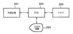
図2は、本実施形態によるプローブ設計方法が適用される情報処理装置の構成を示すブロック図である。本実施形態では、外部記憶装置201、中央処理装置(CPU)202、メモリ203、入出力装置204から構成される情報処理装置に、以下に説明するプローブ設計方法を実行させる。このような構成の情報処理装置としては、例えばパーソナルコンピュータが挙げられる。
【0010】
外部記憶装置201は、本実施形態によるプローブ設計方法を実現するプログラムや、ターゲットの塩基配列データ及びパラメータを保持する。また、本実施形態によって導かれたプローブ配列を保持するのにも使用される。中央処理装置(CPU)202は、プローブ設計のプログラムを実行したり、すべての装置の制御を行なったりする。
【0011】
メモリ203は中央処理装置(CPU)202が実行するプログラム、及びサブルーチンやデータを一時的に記録する。外部記憶装置201に格納されたプローブ設計方法の制御プログラムは、メモリ203にロードされ、中央処理装置202により実行される。入出力装置204は、ユーザとのインタラクションを行う。多くの場合、以下に説明するプローブ設計方法を実現するプログラム実行のトリガはこの入出力装置を介してユーザーが出すことになる。また、ユーザーが結果を見たり、プログラムのパラメータ制御をこの入出力装置を介して行う。
【0012】
図1は、第1の実施形態によるプローブ設計方法の処理手順を説明するフローチャートである。本実施形態のプローブ設計方法処理概要を説明すると、まず、ステップS101において、外部記憶装置201からターゲットの塩基配列データを取得する。次にステップS102において、ステップS101で取得した塩基配列データに基づいて判別ツリーを作成する。判別ツリー及びその作成については後述する。そして、ステップS103において、ステップS102で作成した判別ツリーを外部記憶装置201に格納する。
【0013】
ステップS104では、ステップS103で格納した判別ツリーを用いて、ツリー上に表現されている各プローブ(部分塩基配列)の評価を行なう。すなわち、判別ツリーの中に存在するプローブ候補の中からプローブとしてふさわしいものを選択するための評価を行なう。ステップS105では、上記評価の結果をもとに、最終結果としての最適プローブセットを選択する。ステップS106では最適なプローブを出力する。出力先としては、外部記憶装置201、入出力装置204に含まれる表示装置或いはプリンタ等が挙げられる。
【0014】
以下、各処理について詳細に説明する。
【0015】
[判別ツリーの生成について(ステップS101〜S103)]
図3は、ステップS101で取得する塩基配列データの例を示す図である。図3にある塩基配列情報はHLAまたはMHCと呼ばれる遺伝子群の一部である。この部分は、人間の抗体生成に関連する遺伝子をコーディングしており個体差がある。図3に類似しているが完全に同一ではない塩基配列があるのは、このことを意味している。このHLAに関して現在人類で確認されている遺伝子タイプは100種類以上あり、この種類が異なると生体間移植の際に致命的な拒絶反応がおこる可能性が高い。現在では、患者と臓器提供者のDNAをシークエンスし、完全に塩基配列を決定することによって、このHLAのタイピング(分類)を行っている。この作業を適切なDNAマイクロアレイを用いて行うことによって、簡単かつ高速に行うことができるようになる。
【0016】
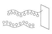
図4はDNAマイクロアレイ上のハイブリダイゼーションの様子を示した図である。生体内でほとんどの場合、DNA塩基配列は2重らせん構造をしていて、その2本鎖の間の結合は塩基間の水素結合で実現されている。一方、RNA塩基配列は1本で存在する場合が多い。塩基の種類はDNAの場合はACGTの4種類、RNAの場合はACGUの4種類であり、それぞれ水素結合ができる塩基対はA−T(U)、G−Cのペアとなっている。以下では、説明のため、DNA塩基配列に関するプローブの作成を例に挙げる。
【0017】
ハイブリダイゼーションとは、1本鎖状態の塩基配列分子同士がある部分の相補的な塩基配列を介して部分的に結合して2本鎖状態を形成することをいう。本実施形態で想定している反応は、図4の上側の基板にくっついた塩基配列(プローブ配列)の方が下側の試料中にある塩基配列分子より短い。よって、試料中に存在する塩基配列分子がプローブ配列を含む場合は、このハイブリダイゼーション反応はうまくいき、試料中のターゲット塩基配列分子はトラップされることとなる。
【0018】
但し、プローブ配列の全ての領域が相補的な場合のみ、ハイブリダイゼーションが可能なわけではなく、一部にペアを形成しない部分があっても、ターゲット塩基配列分子はトラップされることがある。特に、プローブの末端だけの塩基が結合できないような場合は、ハイブリダイゼーションを起こしてしまう可能性が高く、ターゲット塩基配列の正確な選別が出来ない。従って、末端だけが異なるプローブ配列セットは、ハイブリダイゼーションを使った実験には不適格といえる。すなわち、塩基配列中の中央部にターゲットの塩基配列と特異となる配列が存在するものが好ましい。また、ハイブリダイゼーション反応の強度はプローブの塩基配列の長さが長いほど高くなる。よって、理想的にはDNAマイクロアレイ上に配置されるプローブ配列はハイブリダイゼーション強度が似ているもの、すなわち含まれる塩基数が近い塩基配列を選ぶほうが良い。
【0019】
上述のように、最終出力であるプローブ塩基配列は、試料中の部分配列と相補的な塩基配列である必要がある。そこで、本実施形態では、ステップS102の判別ツリー作成処理において、予め全ての部分塩基配列を用意する。この様子を図にしたのが図5である。
【0020】
図5はターゲットとなる塩基配列から得られる部分塩基配列(プローブ)を示す図である。図5で列挙している塩基配列群は、図3のDRB1*0101というタイプの配列の部分配列群の一部である。図5のように、末端を1塩基ずつシフトすることによって、全く異なる部分塩基配列が得られ、この全てがプローブとハイブリダイゼーション反応を行う配列候補となる。あるタイプの対象配列数がnベースだったとすると、その部分塩基配列は全部でn−1個存在することとなる。本実施形態では全ての部分塩基配列を分類する判別ツリーを生成するが、予め所定数の深さを設定し、所定数以上の塩基を有する部分塩基配列について判別ツリーを生成するようにしてもよい。
【0021】
次に、この全ての部分配列を判別/分類する判別ツリーを作成する。図6Aは判別ツリーを説明する図である。ツリーを構成する全てのノードは、4つの子ノード(A,T,G,C)を持つ。それぞれ4つの子ノードは、注目している位置の塩基配列がATGCのいずれかで分類される。まず、一番簡単な例として、注目している位置を1つずつずらす方法を説明する。
【0022】
図6Bは判別ツリーにおける各ノードへの部分塩基配列の分類例を示す図である。ルートノードで、各部分塩基配列の左端の塩基配列を見る。そして、その塩基がどの種類かで部分塩基配列を分類する。例えば、図5に示したHLAのDRB1*0101由来の塩基配列ならば、図5の2番の部分塩基配列はAのノード611に、1,3,5番の部分塩基配列はGのノード612に、4番の部分塩基配列はCのノード613にそれぞれ分類される。そして、1,3,5番の部分配列は、更に深いノードで細分されることとなる。具体的には、1番目の部分塩基配列の次のノードはAであり、3番目の部分塩基配列の次のノードはCであり、5番目の部分塩基配列の次のノードはGである。よって、それぞれ、ノード614、ノード615、ノード616に格納されることになる。
【0023】
以上の様な処理により、全てのターゲットの全ての部分塩基配列について各ノードへの登録を行なって、判別ツリーを作成する。この判別ツリー作成処理では、図5に示したような部分配列に展開したデータを全て対象として判別ツリーを作成するので、作成された判別ツリーの上のどこかに任意の部分塩基配列が登録されることとなる。上記例のように位置を左から一つずつずらす方法で判別ツリーを作成した場合には、ある部分塩基配列の登録されたノードをルートノードへ向けて逆に辿ると、登録された塩基配列の左側の部分がわかることとなる。
【0024】
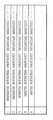
図7及び図8は判別ツリー上のあるノードに登録された部分塩基配列の様子を示す図である。例として、図3に示した4種類の50ベースからなる塩基配列が試料に入っていると仮定する。図6Aで示した判別ツリーの中で、CAGの順でノードを辿っていくと、図6Aのノード601には、図7の表の右側に示した情報が格納されている。すなわち、ノード601には、DRB1*0101…「NULL」、DRB1*04011…「21」、DRB1*07011…「10,37」、DRB1*15011…「21,37」が格納されている。この情報によれば、DRB1*0101にはCAGの部分塩基配列は存在せず(NULL)、DRB1*04011には21番目の場所にCAGが存在し、DRB1*07011には10番目と37番目、DRB1*15011には21番目にそれぞれCAGが存在することが示されている。
【0025】
図7で示したノードに接続される子ノードの中でTとなるノード、すなわち図6Aのノード602の内容を示したのが図8である。このノード602に対応する部分塩基配列はCAGTであり、これにマッチングする部分配列の位置は、DRB1*07011の10番目の部分配列のみである。
【0026】
以上示してきた例は、塩基の種類を左から1つずつずらした位置で見てきた例であり、ノードの順序と塩基配列とが一致している。しかしながら、この位置はアルゴリズムによって変わってもよい。ハイブリダイゼーション反応の場合、中心の塩基配列の相違が重要である。よって、判別ツリーを作成する際に、注目する塩基配列の位置を中心から周辺へ移していくように並べ替えることが一つの有力な方法としてあげられる。
【0027】
例えば、図7の左からC→A→Gとう並びの部分塩基配列に相当するようなノードを、「真中のA」→「右のG」→「左のC」というふうに見ていくことがその方法にあたる。この場合、左から1つずつ見るのではなく、真中、右端、左端の順番で見ていくことになる。従って、左から見る方法だと図7のノード601は{ルートノード→Cのノード→Aのノード→Gのノード}という位置に存在するが、中心から周辺へ見る方法だと、{ルートノード→Aのノード→Gのノード→Cのノード}という位置に存在することになる。このことは、注目する塩基配列(上記例ではCAG)の位置を変えると図6Aにおいてノード601がノード603(A→G→C)に変わることを意味する。この場合、ノード601だけが変わるのではなく、判別ツリー全体の構造が変化する。
【0028】
以上のような並べ替えを一般化して示せば、n個の塩基配列について、nが奇数の場合は(n+1)/2を、nが偶数の場合はn/2をaとした場合に、「a, a+1, a-1, a+2, a-2, … 」というように並べ替えて判別ツリーを構成することになる。もちろん、中心、左端、右端の順番で見ていっても問題ない。
【0029】
以上説明してきた通り、判別ツリー作成処理で判別ツリーが作成されるが、ここで注意するのは、ノードの数は指数関数的に増えていくので、ノードの節約を行わないと必要となるコンピュータリソースが不足することである。具体的には、想定する試料(ターゲット)中にノードに対応する塩基配列が存在しなくなれば、その子ノードの伸張はストップさせるという処理が必要となる。この処理によって、ある以上の深さを超えると、増加するノードは、定常的になる。例えば、判別すべき塩基配列のタイプの数をT、それぞれの全部分配列をNとすると、最悪のケースでもT×N個のノードのみが増えることとなる。
【0030】
[プローブの評価方法について(ステップS104)]
次に図1のプローブ評価処理(S104)を説明する。前述した判別ツリーの全てのノードは試料中に存在しうる部分塩基配列のどれかをコーディングしているので、判別ツリーの全てのノードはプローブの候補となりうる。しかし、ハイブリダイゼーション反応の条件よりプローブとして有効に働く部分塩基配列は限られてくる。このプローブとしての評価をするのが以下に説明するプローブ評価処理である。
【0031】
まず、チップ上に載るプローブ群はハイブリダイゼーション強度が似ているほうがよい。よって、あらかじめプローブの塩基配列の数を決定する方法が考えられる。この場合、判別ツリーのある深さのノードのみがプローブ候補となる。もちろん、この塩基配列の数に幅を持たせてプローブ候補を絞ってもよい。いうまでもなく、この場合はある深さからある深さの範囲のノードがプローブ候補となる。
【0032】
また、厳密に言えば、塩基配列の数が同じでもハイブリダイゼーション強度は異なる。これを計算する方法として、例えば、特開平8−317790「オリゴリボヌクレオチド/オリゴデオキシリボヌクレオチド相補塩基対構造の安定性解析方法」が提案されている。この方法によれば、塩基配列が決まればそのハイブリダイゼーション強度は推定できる。従って、各ノードに対応する塩基配列から各ノードのハイブリダイゼーション強度を推定し、この推定値を元に、判別ツリー上のノード群に絞込を行なう方法もある。但し、この場合、例えば文献“Predicting DNA duplex stability from the base sequence”(Proc. Natl. Acad. Sci. USA Vol. 83, pp. 3746-3750, June 1986 Biochmistry)に記載の方法で、判別ツリー上のノードの塩基配列より、塩基配列の融解温度を求めることになる。
【0033】
本実施形態の非常に優れた点の1つは、判別ツリーが任意の長さの部分塩基配列をコーディングするので、ある範囲の長さやある範囲の融解温度を持ったプローブ候補を選ぶ処理を非常に高速に行なえる点にある。
【0034】
さて、上述の絞込により、例えばある特定の長さ(例えば20ベース)の部分配列を全て含むプローブを設計しても良いのであるが、全てのターゲットに含まれる部分塩基配列には特異性が全くなく、プローブとして意味がない。すなわち、このプローブを使って各ターゲットとハイブリダイゼーション反応を行なっても、何の情報も得ることはできない。よって、判別ツリーのノードによって特定される部分塩基配列の特異性を測る必要がある。この特異性の尺度として通常用いられるのがエントロピーである。
【0035】
例えばターゲットとなる塩基配列タイプが全部でtタイプあり、あるノードに含まれるタイプ毎の部分塩基配列の数がN1,N2,N3,...,Ntであるとすると、そのノードのエントロピーは次の式で計算されることとなる。
【0036】
【数1】
もちろん、ここで説明したエントロピー以外の方法で塩基配列の特異性を測ってもよい。
【0038】
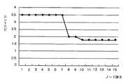
さて、上記の式によって算出されたエントロピーを用いて最適なプローブを探すことになるが、その方法を以下に説明する。図9は、プローブとして典型的に最適なエントロピーの推移をグラフに示した図である。グラフの横軸はノードの深さを示し、この例では15ベースの長さの塩基配列を調べた結果となっている。判別ツリーのノードを辿っていくと、通常、エントロピーは減少していく。例えば、図6Aのノード601よりノード602の方が特異性が高く、エントロピーは減少する。図6Aのノード601、602が図7、図8のような部分塩基配列のセットを保持するとすると、ノード602はDRB1*07011に固有の部分配列に相当し、エントロピーは0となる。
【0039】
図9のグラフで8番目の塩基と10番目の塩基の場所でエントロピーの減少が見られる。つまり、このノードのコーディングする部分塩基配列の8番目と10番目があるタイプセットに特異的な塩基配列であることがグラフからわかる。図9にあるように、中央付近で急激なエントロピー減少があるノードがプローブとして最適となる。
【0040】
本実施形態の非常に優れた点の1つは、このエントロピー減少の様子がノードを深さ方向に辿ることによって、自然と把握することができ、この解析によって、確実に中心位置での塩基特異性を持ったプローブを選べることにある。
【0041】
以上の様なプローブの選択処理を実現するための具体的なプローブ評価関数としては、中心位置にエントロピー減少があると高いスコアになるようなものであればよい。例えば次に示す評価関数を使用することが可能である。
【0042】
【数2】
評価スコア=(エントロピーの減少量)*(1/(中心位置からの距離+1))n
但し、この方法では、予めプローブの長さを想定しなければならい。なぜならば、中心位置はプローブの全長を決定して初めて決定されるからである。
【0043】
予めプローブの長さを制限せずに評価を行なう方法として、判別ツリー作成ステップでも述べた中心から周辺へ塩基のバリエーションを見ていく方法が挙げられる。この方法で判別ツリーを作成した場合、判別ツリーの最初の方で、急激なエントロピー減少があった方がよく、それに対応した評価関数を用意することとなる。
【0044】
例えば、次の評価関数を使用することが可能である。
【0045】
【数3】
評価スコア=(エントロピーの減少量)*(1/(ルートノードからの距離))n
この方法だと任意の長さのプローブ設計に対応できることとなる。
【0046】
以上のような評価関数を導入してプローブの評価を行ない、その評価値を各ノードに格納しておく。
【0047】
図10は本実施形態によるプローブの評価処理(ステップS104)とプローブセットの選択処理(ステップS105)の詳細を示すフローチャートである。ステップS201では、上述したように、塩基数(ノード深さ)や塩基配列に基づく融解温度により、判別ツリー上よりプローブ候補の絞込を行なう。そして、ステップS202において、上記絞込によって得られたプローブ候補のツリー上のパスにある各ノードについて、<数1>によりエントロピーを計算し、各ノードに格納する。そして、ステップS203において、プローブ候補のノードについて、<数2>或いは<数3>に示した評価関数を用いて評価値を算出し、これを当該ノードに格納する。
【0048】
なお、図10において、上記評価関数を用いたプローブの評価は、所定長の或いは所定長範囲の部分塩基配列を抽出して得られたプローブ候補、或いは所定範囲の融解温度を持ったプローブ候補について行うようにしているがこれに限らない。評価を判別ツリー上の全てのプローブについて行い、以下に説明するプローブセットの選択処理時に所定長範囲或いは所定融解温度範囲で絞込を行うようにしてもよい。
【0049】
[プローブセットの選択処理について(ステップS105)]
次に図1のプローブセット選択処理(ステップS105)を説明する。図10のステップS204〜S206はプローブセット選択処理の手順を示している。なお、必要があれば、プローブ候補を抽出して不適当なプローブを排除する。前述のプローブ評価ステップにおいて、ある範囲の長さ、または、ある範囲の融解温度のプローブのみを選んで得られたプローブ候補を評価したが、例えば、このプローブセット選択ステップにおいて、その判断を行うようにしてもよい。その場合、判別ツリー上の全てのプローブについて上述したステップS202とS203のプローブ評価を行なうことになる。
【0050】
ステップS204において、プローブ候補となっている塩基配列の集合を複数のサブセットに分ける。これは冗長なプローブセットを選ぶことを防ぐためである。プローブの特異性を示す情報は、それぞれのターゲット塩基配列タイプに含まれるか含まれないかのビット列で表現できる。例えば、塩基配列タイプがt個存在するとすれば、tビットの情報でプローブの特異性が表現できるわけである。塩基配列タイプが含む場合ビットを1に設定し、含まない場合ビットを0に設定したとすると、例えば全てのタイプの塩基配列に含まれるプローブは全てが1であるtビットの値で表現されることとなる。このtビット列の異なるプローブを異なるグループとするとプローブの特異性を反映したサブセットが出来上がる。この処理によって同じサブセットに含まれる全てのプローブは、同タイプの特異性を持ち、情報的にはプローブとして同じ機能を持つこととなる。従って、各タイプのサブセットから上述したプローブ評価における評価値の高いプローブを選択してこれをマイクロアレイに用いるようにしてもよいが、本実施形態ではこのプローブセットを単位として更なる絞込を行なう。
【0051】
上述のようにプローブ候補の塩基配列群を複数のサブセットに分けると、この複数のサブセットの中から必要でないサブセットを除くことが可能である。この処理を行うと、必要十分な独立プローブセットが出来上がる。以下に、具体的に例を示してこの処理を説明する。
【0052】
ターゲットとなる塩基配列タイプがA、B、C、Dの4種類だったとする。いま、プローブ候補の塩基配列がその特異性に関して5つのサブグループに分けられるとすると、それぞれのサブグループの特異性が前述の4ビットの値で表せることとなる。ここで、例えば5つのサブグループが、1010,1100,0001,1110,0111というようなビット列でその特異性が表せたとする。すると実は、情報的には最初の2つのサブグループ(1010,1100)で4つのタイプを決定することは必要十分にできるのである。
【0053】
この場合、最初の2つのサブグループの中から選んだプローブをα、βとすると、もし試料がAタイプの塩基配列ならば、αβともにハイブリダイゼーション反応する。同様に、試料がBタイプならαにはハイブリダイゼーション反応は起こらずβに対してのみ反応が起こる。試料がCタイプならαにのみハイブリダイゼーション反応が起き、βには起きない。試料がDタイプならα、βともにハイブリダイゼーション反応は起こらない。
【0054】
もし実験が完全に制御できて、上記のハイブリダイゼーション反応の発生、非発生情報が非常に高い確率で得られたとすると、ターゲットとなるA、B、C、Dの4種類のタイプを判別する塩基プローブは、1番目と2番目のサブグループに含まれるプローブで必要十分となる。このような状況を情報的な観点でいうと、1番目と2番目のサブグループが独立で、その生成する情報空間に3番目、4番目、5番目のサブグループが従属しているという。よって、3番目、4番目、5番目のサブグループに属するプローブ候補は厳密に言えば必要なくなる。
【0055】
なお、この必要十分な独立サブセットの組を選ぶ処理は非常に時間のかかる処理となる。また、実際は、最終的に選択するプローブセットは、ある程度冗長に選ぶ必要がある場合が多い。というのも、コンピュータの扱うデータと違って、生体物質の反応の結果として得られるデータは、実験の途中で多くのノイズが入る可能性が高く、必要最低限のプローブセットしか用意していないと、このノイズの多い場合に的確な実験結果を再現できないこととなるためである。よって、実際は上で述べたような必要十分な独立サブセットのみを選ぶ必要はない場合が多い。
【0056】
ステップS205では以上のようにしてプローブセットを選択し、最終的に、対象となるプローブ候補のサブセットを得る。そして、選択されたそれぞれのサブセットの中で、プローブ評価ステップで得られた評価値の高いプローブを最終的なプローブセットとして選択する。なお、本実施形態では、上記手順で得られる塩基配列はターゲットの塩基配列から抽出された部分塩基配列そのものの配列順序を有するので、ステップS106で、選択された部分塩基配列を相補的な塩基配列に変換して出力することになる。例えば、ステップS105で部分塩基配列「GAGCG」が選択されていれば、ステップS106では、これに対応するプローブとして「CTCGC」が出力されることになる。もちろん、ステップS102において判別ツリーを作成する時点で、ターゲットの塩基配列と相補的な塩基配列を用いてもよい。この場合は、ステップS105で選択されるプローブの塩基配列がそのままステップS106で出力されることになる。
【0057】
以上のようにして選択されたプローブを用いることにより、DNAマイクロアレイシステムに最適なオリゴヌクレオチドプローブの設計が実現できる。そして、このことにより、より確かな遺伝子発現情報や、個体識別情報が得られるという効果がある。
なお、上記実施形態において説明した評価については、種々の変形が考えられる。例えば、評価関数によって求めた値が所定値を超える場合に、即座にそのノードに対応する部分塩基配列をプローブとして決定するように処理を簡略化することも可能である。或いは<数1>で算出したエントロピーの変化量が所定値を超える部分を有する部分塩基配列をプローブとして決定するように処理を簡略化することも可能である。
【0058】
<第2の実施形態>
第1の実施形態ではプローブ選択のために判別ツリーを生成し、これに基づいてプローブ評価を行なった。第2の実施形態では、判別ツリーの代わりにハッシュ表を用いる。以下、第2の実施形態の処理を説明する。なお、装置構成は第1の実施形態(図2)と同様であるので説明を省略する。
【0059】
図11は第2の実施形態によるプローブ設計方法の処理手順を説明するフローチャートである。ステップS1001においてターゲットの塩基配列データを取得し、ステップS1002において、取得された塩基配列データに含まれるある長さの範囲の部分塩基配列を分類する部分配列ハッシュ表を作成する。そして、ステップS1003において、ステップS1002で作成された部分塩基配列ハッシュ表を外部記憶装置201に格納する。
【0060】
ステップS1004は部分塩基配列ハッシュ表に存在するプローブ候補について、プローブとしてふさわしいかどうかを評価するプローブ評価処理を実行する。ステップS1005では、更にプローブセットの選択を行ない、上記プローブ評価の結果を元に最終結果の最適プローブを選択する。ステップS1006は、最終結果として得られた最適プローブである。上記処理において、入力はターゲットとなる塩基配列データであり、出力はマイクロアレイに搭載するのに適したプローブである。
【0061】
[部分塩基配列ハッシュ表の生成について(S1002、S1003)]
第2の実施形態では、第1の実施形態で説明した判別ツリーを作成する替わりに、部分塩基配列ハッシュ表を作成する。これは判別ツリーのある深さのノードを作成するのに対応する。ハッシュ表とはソフトウェア技術として非常によく使われる方法で、大量のバリエーションのありうる情報列をコンパクトに保存する方法である。
【0062】
例えば、20ベースの長さの部分塩基配列がターゲットとなる塩基配列の中にどのように含まれるかを見る場合を考えてみる。20ベースの塩基配列の取りうるバリエーションは、理論的には420(=40ビット)となる。これだけの大きな空間を用意することは事実上不可能である。一方、試料中に存在しうる塩基配列のバリエーションは、この40ビットの空間と比べると、極めて小さい。よって、20ベースの部分塩基配列を40ビットの値にコーディングしておいて、それを例えば十分大きな素数でわることによって、事実上重複のないコンパクトな空間に収めることができる。この方法をハッシュ表を用いたデータ格納整理方法と呼んでいる。なお、仮に実際は異なる塩基配列にもかかわらず、重複が生じた場合は、2重にハッシュ表を用意するとか、ハッシュ表の次の番地に格納するというような回避方法がある。
【0063】
ハッシュ表を用いて、ターゲットの塩基配列の中の特定の長さの全部分配列が格納整理できると、それが含まれる塩基配列の種類と位置も自動的に特定できる。これは、図7や図8の左のカラムがハッシュ表のそれぞれのエントリーに登録されている状態と同じである。このことによって、実施形態1の判別ツリーのある深さのノード情報が全て得られたことになる。
【0064】
この操作を複数の長さの部分塩基配列に対して実施することによって、第1の実施形態である深さからある深さまでの全てのノード展開ができたことと同じになる。第1の実施形態で述べたとおり、ある範囲の長さのプローブやある範囲の融解温度のプローブを設計する場合は、これでプローブ候補が全て得られたこととなる。
【0065】
[プローブ候補の評価について(S1004)]
次に、この全てのプローブ候補から、プローブとして適切か否かを判定するためのプローブ評価について説明する。第2の実施形態が第1の実施形態と決定的に異なるところは、このプローブ評価処理である。第2の実施形態は第1の実施形態より若干性能が劣る。つまり、第1の実施形態の方がより高性能なプローブを設計できる場合が多い。しかしながら、第2の実施形態は、処理の簡易さ、迅速さにおいて第1の実施形態を上回るものであり、その利用価値は高いものである。
【0066】
第1の実施形態でも述べたとおり、プローブの塩基配列の特異性は中央部分に存在するほうがプローブとしては質が高い。よって、その中央部の特異性を調べたいのであるが、第1の実施形態と違って、塩基配列中の部分的な情報が全くないので非常に困難である。そこで、第2の実施形態では、ターゲットの塩基配列中に存在する特異点(特異塩基位置という)を予め求める。この様子を示したのが図12である。図12の表の一番下に表示したのが特異塩基位置である。*のマークのある場所が、ターゲットの塩基配列の全てが共通とはなっていない箇所、すなわちあるタイプ間に特異性がある場所(特異塩基位置)である。そして、この位置を中央に含むプローブ候補が良質なプローブとなる。この特異塩基位置のプローブ候補中での場所を評価する関数を使って、プローブ候補の質を評価する。
【0067】
具体的には、例えば、
【数4】
評価スコア=Σ{1/(中心位置からの特異塩基位置の距離+1)}n}
というような評価関数を利用して判定することができる。
【0068】
また、上述の例では、特異塩基位置の判定において、特異性があるかないかの2値で評価していたが、実施形態1に示したようなエントロピーのような尺度を使用して、連続値で評価しても問題ない。例えば、図12の*のマークのあるところは、特異塩基配列と呼ばれるが、場所によってはほとんどがGで、一種類のタイプだけAである場所(エントロピーの減少量が低い)と、半分のタイプがGで、残りの半分のタイプがAである場所(エントロピーの減少量が高い)が混じっている。上述したように、エントロピーの減少量が多い場所が中央にあったほうが判別に有利なので、<数4>に対してそのような重み付けを行なうこと、例えば、特異塩基配列の位置におけるエントロピーの減少量を<数4>に積算するというような重み付けをすることで、より正確なプローブ候補の質評価が可能となる。
【0069】
[プローブセット選択処理(S1005)]
ステップS1005で実行されるプローブセット選択処理は、第1の実施形態(ステップS106)と同様の処理を行うものであり、説明を省略する。
【0070】
以上のように第2の実施形態によれば、ハッシュ表を用いてプローブ候補を選択するので、処理の簡素化、高速化が達成される。
【0071】
以上説明したように、第1或いは第2の実施形態のプローブ設計処理に従って得られた塩基プローブを基板上に配置することで、ターゲットのタイピングに好適な塩基プローブを含むDNAマイクロアレイが得られることになる。なお、塩基プローブが決定されれば、周知のDNAマイクロアレイの製造方法を用いて、所定のターゲットに対して好適なDNAマイクロアレイを製造することができる。また、このようなDNAマイクロアレイを用いる遺伝子検査装置を提供することで、ターゲットのタイピングを良好に実現することができる。なお、DNAマイクロアレイの製造方法と構造、およびこれを用いた遺伝子検査装置そのものは周知であるので、その詳細な説明を省略する。
【0072】
<第3実施形態>
上述の各実施形態においては、PCRなどの手法を用いて、調べたいDNA、あるいは、RNA(cDNA)の塩基配列を増幅して検体溶液を作成するのが、最も一般的であった。この場合、検体中に存在する塩基配列は、調べたい塩基配列をその部分配列として包含している可能性が非常に高かった。即ち、第1及び第2実施形態は、PCR等の実験手法を用いた検体調製をした場合に、特に好適である。
【0073】
ところが、例えば細胞中に存在するRNAをまとめて抽出し、その中の一部のRNAの存在量を測定するといった目的の場合、作成したDNAマイクロアレイと反応する可能性のある塩基配列は、細胞中に存在する全てのRNAとなる。そして、これらのRNA、あるいはそれから作成されたcDNAの塩基配列の中に調べたい塩基配列が存在する確率は極めて低い。
【0074】
これを図を使って説明すると、図13のようになる。第1及び第2実施形態では、「検体中に存在する可能性のある塩基配列、あるいはその部分塩基配列」と、「調べたい塩基配列、あるいはその部分塩基配列」は、ほとんど同じ集合であった。これを第1及び第2実施形態においては、ターゲット塩基配列と呼んでいた。例えば、MHCなどの人体特異性を示す遺伝子DNAの解析などは、この場合に当てはまる。
【0075】
これに対して、上述のようなRNAの発現量を測定する実験の場合、検体中に存在する塩基配列は、調べたい塩基配列に対して、圧倒的に種類が多いのが一般的である。よって、この場合は、検体中に存在する可能性のある全ての塩基配列が特異性の対象となるターゲット塩基配列となる。そして、調べたい塩基配列は、そのターゲット塩基配列の一部となる。
【0076】
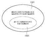
図13で説明すると、第1実施形態の判別ツリー、または、第2実施形態のハッシュテーブルを作成するに際して、使用される塩基配列は、図13の「検体中に存在する可能性のある塩基配列の全部分塩基配列」(1301)となる。そして、調べたい塩基配列の部分配列の特異性は、全体であるターゲット塩基配列との特異性に基づいて導かれ、プローブ候補が決定されることとなる。
【0077】
以下、図14、図15を用いて、第3実施形態によるプローブ設計方法を具体的に説明する。
【0078】
まず、第1実施形態と同様の判別ツリーを用いたプローブ設計手順について図14を用いて説明する。ステップS1401において、検体中に存在する可能性のある全塩基配列であるターゲット塩基配列1411を取得する。この中には、調べたい塩基配列データ1410が含まれる。ターゲット塩基配列1411は、図13に示されるように、調べたい塩基配列1302を含む塩基配列集合1301である。
【0079】
ステップS1402では、ステップS1401で得られたターゲット塩基配列データ1411より得られる複数の部分塩基配列を分類する判別ツリー1412を生成する。判別ツリーの生成については第1実施形態(ステップS102、S103)で説明したとおりである。
【0080】
次に、ステップS1403において、判別ツリー1412の中に存在するプローブ候補についてプローブとしてどの程度ふさわしいかを評価する。評価の方法は第1の実施形態(ステップS104)と同様である。但し、プローブとして選ばれる部分塩基配列は、調べたい塩基配列データ1410の部分配列の中から選ばれ、その特異性は、ターゲット塩基配列データ1411をもとに求められることとなる。
【0081】
続いて、ステップS1404において、ステップS1403におけるプローブの評価結果に基づいて最終結果の最適プローブセットを選択する。この処理は第1の実施形態のステップS105と同様である。そして、ステップS1405において、ステップS1404で選択されたプローブが最適プローブとして出力される。本実施形態の入力は、調べたい塩基配列データであり、出力は調べたい塩基配列に含まれる最適プローブセット、またはその相補鎖となる。
【0082】
次に、第2実施形態と同様のハッシュテーブルを用いたプローブ設計手順について図15を参照して説明する。
【0083】
ステップS1501において、検体中に存在する可能性のある全塩基配列であるターゲット塩基配列1511を取得する。この中には、調べたい塩基配列データ1510が含まれる。ターゲット塩基配列1511は、図13に示されるように、調べたい塩基配列1302を含む塩基配列集合1301である。
【0084】
ステップS1502では、ステップS1501で得られたターゲット塩基配列データ1511より得られる複数の部分塩基配列を分類する部分塩基配列ハッシュ表1512を生成する。部分塩基配列ハッシュ表1512の生成については第2実施形態(ステップS1002、S1003)で説明したとおりである。
【0085】
次に、ステップS1503において、部分塩基配列ハッシュ表1512の中に存在するプローブ候補についてプローブとしてどの程度ふさわしいかを評価する。評価の方法は第2の実施形態(ステップS1004)と同様である。但し、プローブとして選ばれる部分塩基配列は、調べたい塩基配列データ1510の部分配列の中から選ばれ、その特異性は、ターゲット塩基配列データ1511をもとに求められることとなる。
【0086】
続いて、ステップS1504において、ステップS1503におけるプローブの評価結果に基づいて最終結果の最適プローブセットを選択する。この処理は第2の実施形態のステップS1005と同様である。そして、ステップS1505において、ステップS1504で選択されたプローブが最適プローブとして出力される。本実施形態の入力は、調べたい塩基配列データであり、出力は調べたい塩基配列に含まれる最適プローブセット、またはその相補鎖となる。
【0087】
以上のように、本実施形態によれば、例えば細胞中に存在するRNAをまとめて抽出し、その中の一部のRNAの存在量を測定するといった用途に対して、適切なマイクロアレイを設計することが可能となる。
【0088】
また、本発明の目的は、前述した実施形態の機能を実現するソフトウェアのプログラムコードを記録した記憶媒体を、システムあるいは装置に供給し、そのシステムあるいは装置のコンピュータ(またはCPUやMPU)が記憶媒体に格納されたプログラムコードを読出し実行することによっても、達成されることは言うまでもない。
【0089】
この場合、記憶媒体から読出されたプログラムコード自体が前述した実施形態の機能を実現することになり、そのプログラムコードを記憶した記憶媒体は本発明を構成することになる。
【0090】
プログラムコードを供給するための記憶媒体としては、例えば、フロッピディスク,ハードディスク,光ディスク,光磁気ディスク,CD−ROM,CD−R,磁気テープ,不揮発性のメモリカード,ROMなどを用いることができる。
【0091】
また、コンピュータが読出したプログラムコードを実行することにより、前述した実施形態の機能が実現されるだけでなく、そのプログラムコードの指示に基づき、コンピュータ上で稼働しているOS(オペレーティングシステム)などが実際の処理の一部または全部を行い、その処理によって前述した実施形態の機能が実現される場合も含まれることは言うまでもない。
【0092】
さらに、記憶媒体から読出されたプログラムコードが、コンピュータに挿入された機能拡張ボードやコンピュータに接続された機能拡張ユニットに備わるメモリに書込まれた後、そのプログラムコードの指示に基づき、その機能拡張ボードや機能拡張ユニットに備わるCPUなどが実際の処理の一部または全部を行い、その処理によって前述した実施形態の機能が実現される場合も含まれることは言うまでもない。
【0093】
【発明の効果】
以上説明したように、本発明によれば、解析対象となるターゲットの塩基配列に応じて、解析に適切なプローブを自動的に選択することが可能となり、プローブ設計の効果的な支援が実現される。
【0094】
【配列表】
【図面の簡単な説明】
【図1】第1の実施形態によるプローブ設計方法の処理手順を説明するフローチャートである。
【図2】本実施形態によるプローブ設計方法が適用される情報処理装置の構成を示すブロック図である。
【図3】ステップS101で取得する塩基配列データの例を示す図である。
【図4】DNAマイクロアレイ上のハイブリダイゼーションの様子を示した図である。
【図5】ターゲットとなる塩基配列から得られる部分塩基配列(プローブ)を示す図である。
【図6A】第1の実施形態における判別ツリーを説明する図である。
【図6B】判別ツリーにおける各ノードの内容例を示す図である。
【図7】判別ツリー上における、あるノードに登録された部分塩基配列の様子を示す図である。
【図8】判別ツリー上における、あるノードに登録された部分塩基配列の様子を示す図である。
【図9】プローブとして典型的に最適なエントロピーの推移をグラフに示した図である。
【図10】第1の実施形態によるプローブの評価処理(ステップS104)とプローブセットの選択処理(ステップS105)の詳細を示すフローチャートである。
【図11】第2の実施形態によるプローブ設計方法の処理手順を説明するフローチャートである。
【図12】第2の実施形態による、ターゲット中の特異塩基位置を説明する図である。
【図13】第3の実施形態によるプローブ設計方法が適用される塩基配列データの状態を説明する図である。
【図14】第3の実施形態による、判別ツリーを用いたプローブ設計方法を説明するフローチャートである。
【図15】第3の実施形態による、ハッシュ表を用いたプローブ設計方法を説明するフローチャートである。[0001]
BACKGROUND OF THE INVENTION
The present invention relates to an information processing apparatus and probe design method suitable for supporting microarray design in which a plurality of nucleic acid probes are arranged.
[0002]
[Prior art]
Conventionally, as disclosed in Japanese Patent Application Laid-Open No. 10-272000 or Japanese Patent Application Laid-Open No. 11-187900, a system for determining gene expression and sequence using a DNA microarray has been proposed. In this system, it is necessary to design a base sequence fragment (probe) to be hybridized with a sample in advance. If a good probe set can be designed, it is a feature that a large amount of information on a fragment of a base sequence existing in a sample can be obtained with a very high probability.
[0003]
[Problems to be solved by the invention]
However, the base sequence fragments that may exist in the sample (target) to be analyzed are very diverse, and are completely different if the experimental system is different. In this case, it is necessary to design a completely different probe. Conventionally, this probe design has been performed manually based on experience, but now that a large number of base sequences are being determined, it is practically impossible to perform probe design one by one.
[0004]
[Means for Solving the Problems]
The present invention has been made in view of the above problems, and it is possible to automatically select an appropriate probe for analysis according to the base sequence of a target to be analyzed, and to effectively perform probe design. The purpose is to support.
[0005]
In order to achieve the above object, a probe design method according to the present invention comprises:
A probe design method for designing a probe using a probe design device for designing a base sequence used for a probe for performing a gene analysis by performing a hybridization reaction with an unknown nucleic acid fragment,
A generating step for generating a tree in which a plurality of partial base sequences obtained based on a target base sequence are arranged on a node path;In the tree, each hierarchy has a one-to-one correspondence with each base position in the partial base sequence, each node corresponds to a base at a predetermined position in the partial base sequence,
With respect to the node selected from the tree, the evaluation means determines that the selected node is based on the number of partial base sequences arranged in each node existing in the path on the tree connected to the selected node. Of the partial base sequenceCalculate the specificity at each position, and based on the calculated multiple specificity and their positionAn evaluation process for evaluating the availability as a probe;
A determination step of determining a partial base sequence to be used as a probe based on the evaluation result of the evaluation step;Get.
[0006]
In addition, a probe design method according to another aspect of the present invention for achieving the above object is as follows:
A probe design method for designing a probe using a probe design device for designing a base sequence used for a probe for performing a gene analysis by performing a hybridization reaction with an unknown nucleic acid fragment,
A generating step for generating a discriminant tree for classifying a list of a plurality of partial base sequences obtained from the target base sequence data;In the tree, each hierarchy has a one-to-one correspondence with each base position in the partial base sequence, each node corresponds to a base at a predetermined position in the partial base sequence,
Evaluation means for probe candidates existing in the discrimination tree,Based on the number of partial base sequences arranged at each node existing in the path on the tree corresponding to the probe candidate, the specificity at each position of the partial base sequence of the probe candidate was calculated and calculated Based on multiple specificities and their locationAn evaluation process for evaluating the availability as a probe;
And a selection step of selecting a probe to be used based on the evaluation result of the evaluation step.Get.
[0007]
DETAILED DESCRIPTION OF THE INVENTION
Hereinafter, preferred embodiments of the present invention will be described with reference to the accompanying drawings.
[0008]
<First Embodiment>
[Outline of device and operation]
In the following embodiment, a probe design method for designing an optimal oligonucleotide probe used in a nucleic acid sequence analysis system using a so-called DNA microarray using a computer and an apparatus for executing the probe design method will be described.
[0009]
FIG. 2 is a block diagram illustrating a configuration of an information processing apparatus to which the probe design method according to the present embodiment is applied. In this embodiment, an information processing apparatus including an
[0010]
The
[0011]
The
[0012]
FIG. 1 is a flowchart for explaining the processing procedure of the probe design method according to the first embodiment. The outline of the probe design method processing of this embodiment will be described. First, in step S101, target base sequence data is acquired from the
[0013]
In step S104, each probe (partial base sequence) expressed on the tree is evaluated using the discrimination tree stored in step S103. That is, evaluation is performed to select a probe suitable from the probe candidates existing in the discrimination tree. In step S105, the optimum probe set as the final result is selected based on the evaluation result. In step S106, an optimum probe is output. Examples of the output destination include a display device or a printer included in the
[0014]
Hereinafter, each process will be described in detail.
[0015]
[Generation of Discrimination Tree (Steps S101 to S103)]
FIG. 3 is a diagram illustrating an example of the base sequence data acquired in step S101. The base sequence information in FIG. 3 is part of a gene group called HLA or MHC. This part codes genes related to human antibody production, and there are individual differences. This means that there is a base sequence similar to FIG. 3 but not completely identical. There are more than 100 gene types currently confirmed by humans for this HLA, and if these types are different, there is a high possibility that a fatal rejection will occur during inter-vivo transplantation. Currently, the HLA typing (classification) is performed by sequencing the DNA of the patient and the organ donor and determining the complete nucleotide sequence. By performing this operation using an appropriate DNA microarray, the operation can be performed easily and at high speed.
[0016]
FIG. 4 shows the state of hybridization on the DNA microarray. In most cases, the DNA base sequence has a double helix structure in vivo, and the bond between the two strands is realized by a hydrogen bond between the bases. On the other hand, a single RNA base sequence often exists. The types of bases are 4 types of ACGT in the case of DNA, and 4 types of ACGU in the case of RNA. The base pairs capable of hydrogen bonding are AT (U) and GC pairs. In the following, for the sake of explanation, the creation of a probe relating to a DNA base sequence is taken as an example.
[0017]
Hybridization means that a single-stranded base sequence molecule is partially bonded via a part of a complementary base sequence to form a double-stranded state. In the reaction assumed in this embodiment, the base sequence (probe sequence) attached to the upper substrate in FIG. 4 is shorter than the base sequence molecules in the lower sample. Therefore, when the base sequence molecule present in the sample includes a probe sequence, this hybridization reaction is successful, and the target base sequence molecule in the sample is trapped.
[0018]
However, hybridization is not possible only when all the regions of the probe sequence are complementary, and the target base sequence molecule may be trapped even if there is a part that does not form a pair. In particular, when a base only at the end of the probe cannot bind, there is a high possibility that hybridization will occur, and the target base sequence cannot be accurately selected. Thus, probe sequence sets that differ only at the ends are ineligible for experiments using hybridization. That is, the base sequence preferably has a sequence that is specific to the target base sequence at the center. Further, the strength of the hybridization reaction increases as the length of the probe base sequence increases. Therefore, ideally, it is better to select probe sequences arranged on the DNA microarray that have similar hybridization intensities, that is, base sequences with a similar number of bases.
[0019]
As described above, the probe base sequence that is the final output needs to be a base sequence that is complementary to the partial sequence in the sample. Therefore, in the present embodiment, all partial base sequences are prepared in advance in the discrimination tree creation process in step S102. This is illustrated in FIG.
[0020]
FIG. 5 is a diagram showing a partial base sequence (probe) obtained from the target base sequence. The base sequence group listed in FIG. 5 is a part of a partial sequence group of a sequence of the type DRB1 * 0101 in FIG. As shown in FIG. 5, a completely different partial base sequence is obtained by shifting the end by one base at a time, and all of these are sequence candidates for performing a hybridization reaction with the probe. If the number of target sequences of a certain type is n-based, there will be n-1 partial base sequences in total. In this embodiment, a discrimination tree for classifying all partial base sequences is generated. However, a predetermined number of depths may be set in advance, and a discrimination tree may be generated for partial base sequences having a predetermined number of bases or more. .
[0021]
Next, a discrimination tree for discriminating / classifying all the partial arrays is created. FIG. 6A is a diagram illustrating a discrimination tree. All nodes constituting the tree have four child nodes (A, T, G, C). Each of the four child nodes is classified according to the ATGC of the base sequence at the target position. First, as the simplest example, a method of shifting the target position one by one will be described.
[0022]
FIG. 6B is a diagram illustrating a classification example of partial base sequences to each node in the discrimination tree. At the root node, look at the base sequence at the left end of each partial base sequence. Then, the partial base sequence is classified according to the type of the base. For example, in the case of the base sequence derived from DRB1 * 0101 of HLA shown in FIG. 5, the second partial base sequence in FIG. 5 is the
[0023]
Through the process as described above, all partial base sequences of all targets are registered in each node to create a discrimination tree. In this discriminant tree creation process, a discriminant tree is created for all the data expanded into the partial sequence as shown in FIG. 5, so that an arbitrary partial base sequence is registered somewhere on the created discriminant tree. The Rukoto. When the discrimination tree is created by shifting the position one by one from the left as in the above example, when the registered node of a certain partial base sequence is traced back to the root node, the registered base sequence You will see the left part.
[0024]
7 and 8 are diagrams showing a partial base sequence registered in a certain node on the discrimination tree. As an example, it is assumed that the base sequence consisting of the four types of 50 bases shown in FIG. When the nodes are traced in the order of CAG in the discrimination tree shown in FIG. 6A, the information shown on the right side of the table in FIG. 7 is stored in the
[0025]
FIG. 8 shows the contents of the node that is T among the child nodes connected to the node shown in FIG. 7, that is, the contents of the
[0026]
The example shown above is an example in which the types of bases are viewed at positions shifted one by one from the left, and the order of the nodes matches the base sequence. However, this position may vary depending on the algorithm. In the case of a hybridization reaction, the difference in the central base sequence is important. Therefore, when creating a discrimination tree, one effective method is to rearrange the base sequence of interest so that the position of the base sequence is shifted from the center to the periphery.
[0027]
For example, from the left in FIG. 7, the nodes corresponding to the partial base sequences in the order of C → A → G are viewed as “middle A” → “right G” → “left C”. Is the method. In this case, instead of looking one by one from the left, it is seen in the order of the middle, right edge, and left edge. Accordingly, when viewed from the left, the
[0028]
If the above sort is generalized, for n base sequences, when n is an odd number, (n + 1) / 2 is used, and when n is an even number, n / 2 is set to a. , “A, a + 1, a-1, a + 2, a-2,...” Are rearranged to form a discrimination tree. Of course, there is no problem even if you look in the order of the center, left edge, and right edge.
[0029]
As described above, a discrimination tree is created by the discrimination tree creation process, but it should be noted that the number of nodes increases exponentially, so it is necessary to save the number of nodes. There is a shortage of resources. Specifically, when the base sequence corresponding to the node does not exist in the assumed sample (target), it is necessary to stop the extension of the child node. By this process, when the depth exceeds a certain depth, the increasing node becomes stationary. For example, if T is the number of types of base sequences to be distinguished and N is the total number of each partial sequence, only T × N nodes are added even in the worst case.
[0030]
[About Probe Evaluation Method (Step S104)]
Next, the probe evaluation process (S104) of FIG. 1 will be described. Since all the nodes of the discrimination tree described above code any one of the partial base sequences that can exist in the sample, all the nodes of the discrimination tree can be probe candidates. However, the partial base sequence that works effectively as a probe is limited depending on the conditions of the hybridization reaction. This probe evaluation is performed in the probe evaluation process described below.
[0031]
First, it is better that the probe groups placed on the chip have similar hybridization intensities. Therefore, a method of determining the number of probe base sequences in advance can be considered. In this case, only a node at a certain depth of the discrimination tree is a probe candidate. Of course, the probe candidates may be narrowed by giving a range to the number of base sequences. Needless to say, in this case, a node in a range from a certain depth to a certain depth is a probe candidate.
[0032]
Strictly speaking, the hybridization intensity is different even if the number of base sequences is the same. As a method for calculating this, for example, JP-A-8-317790 “Method for analyzing stability of oligoribonucleotide / oligodeoxyribonucleotide complementary base pair structure” has been proposed. According to this method, once the base sequence is determined, the hybridization intensity can be estimated. Accordingly, there is a method in which the hybridization intensity of each node is estimated from the base sequence corresponding to each node, and the nodes on the discrimination tree are narrowed down based on this estimated value. However, in this case, for example, the method described in the document “Predicting DNA duplex stability from the base sequence” (Proc. Natl. Acad. Sci. USA Vol. 83, pp. 3746-3750, June 1986 Biochmistry) The melting temperature of the base sequence is obtained from the base sequence of the node.
[0033]
One of the very excellent points of this embodiment is that the discrimination tree codes a partial base sequence of an arbitrary length, so that the process of selecting probe candidates having a certain range of length and a certain range of melting temperature is very difficult. It can be done at high speed.
[0034]
By the above-mentioned narrowing down, for example, a probe including all partial sequences of a specific length (for example, 20 bases) may be designed. However, the partial base sequences included in all targets have specificity. There is no meaning as a probe. That is, no information can be obtained even if a hybridization reaction is carried out with each target using this probe. Therefore, it is necessary to measure the specificity of the partial base sequence specified by the node of the discrimination tree. Entropy is commonly used as a measure of this specificity.
[0035]
For example, there are t types of target base sequence types in total, and the number of partial base sequences for each type included in a node is N1, N2, N3,. . . , Nt, the entropy of the node is calculated by the following equation.
[0036]
[Expression 1]
Of course, the specificity of the base sequence may be measured by a method other than the entropy described here.
[0038]
Now, an optimal probe is searched for using the entropy calculated by the above formula. The method will be described below. FIG. 9 is a graph showing a transition of entropy that is typically optimal as a probe. The horizontal axis of the graph indicates the depth of the node. In this example, the base sequence having a length of 15 bases is examined. As the nodes of the discrimination tree are traced, the entropy usually decreases. For example, the
[0039]
In the graph of FIG. 9, a decrease in entropy is observed at the positions of the eighth base and the tenth base. That is, it can be seen from the graph that the base sequence is specific to the type set having the 8th and 10th partial base sequences coded by this node. As shown in FIG. 9, a node having a sharp entropy decrease near the center is optimal as a probe.
[0040]
One of the very excellent points of this embodiment is that the state of this entropy reduction can be grasped naturally by tracing the node in the depth direction, and this analysis ensures that the base is specific at the center position. It is to be able to choose a probe with sex.
[0041]
As a specific probe evaluation function for realizing the probe selection process as described above, any function that has a high score when there is a decrease in entropy at the center position may be used. For example, the following evaluation function can be used.
[0042]
[Expression 2]
Evaluation score = (Decrease in entropy) * (1 / (Distance from center position + 1))n
However, in this method, the length of the probe must be assumed in advance. This is because the center position is determined only after the total length of the probe is determined.
[0043]
As a method of performing evaluation without limiting the length of the probe in advance, there is a method of looking at base variations from the center to the periphery described in the discrimination tree creation step. When a discrimination tree is created by this method, it is better that there is a sharp entropy decrease at the beginning of the discrimination tree, and an evaluation function corresponding to that is prepared.
[0044]
For example, the following evaluation function can be used.
[0045]
[Equation 3]
Evaluation score = (Decrease in entropy) * (1 / (Distance from root node))n
With this method, it is possible to cope with a probe design of an arbitrary length.
[0046]
The evaluation function as described above is introduced to evaluate the probe, and the evaluation value is stored in each node.
[0047]
FIG. 10 is a flowchart showing details of the probe evaluation process (step S104) and the probe set selection process (step S105) according to this embodiment. In step S201, as described above, probe candidates are narrowed down on the discrimination tree based on the number of bases (node depth) and the melting temperature based on the base sequence. In step S202, for each node in the path on the probe candidate tree obtained by the above-described narrowing, entropy is calculated according to <
[0048]
In FIG. 10, the evaluation of the probe using the evaluation function is performed on a probe candidate obtained by extracting a partial base sequence having a predetermined length or a predetermined length range, or a probe candidate having a melting temperature within a predetermined range. I do it, but it is not limited to this. The evaluation may be performed for all probes on the discrimination tree, and narrowing may be performed within a predetermined length range or a predetermined melting temperature range during probe set selection processing described below.
[0049]
[Probe Set Selection Processing (Step S105)]
Next, the probe set selection process (step S105) in FIG. 1 will be described. Steps S204 to S206 in FIG. 10 show the procedure of the probe set selection process. If necessary, probe candidates are extracted to eliminate inappropriate probes. In the probe evaluation step described above, probe candidates obtained by selecting only probes having a certain range of length or a certain range of melting temperature were evaluated. For example, in this probe set selection step, the determination is made. It may be. In that case, the probe evaluation in steps S202 and S203 described above is performed for all probes on the discrimination tree.
[0050]
In step S204, the set of base sequences serving as probe candidates is divided into a plurality of subsets. This is to prevent selecting redundant probe sets. Information indicating the specificity of the probe can be expressed as a bit string that is included or not included in each target base sequence type. For example, if there are t base sequence types, the probe specificity can be expressed by t-bit information. If the bit is set to 1 when the base sequence type is included, and the bit is set to 0 when it is not included, for example, probes included in all types of base sequences are represented by t-bit values that are all 1 It will be. If the probes having different t bit strings are grouped in different groups, a subset reflecting the specificity of the probe is completed. By this processing, all the probes included in the same subset have the same type of specificity and have the same function as probes in terms of information. Therefore, a probe having a high evaluation value in the probe evaluation described above may be selected from each type of subset and used for the microarray. However, in this embodiment, further narrowing down is performed in units of this probe set.
[0051]
As described above, when the probe candidate base sequence group is divided into a plurality of subsets, unnecessary subsets can be excluded from the plurality of subsets. When this process is performed, a necessary and sufficient independent probe set is completed. This process will be described below with a specific example.
[0052]
Assume that the target base sequence types are A, B, C, and D. If the base sequences of probe candidates are divided into five subgroups with respect to their specificity, the specificity of each subgroup can be represented by the aforementioned 4-bit value. Here, for example, it is assumed that singularities of five subgroups can be expressed by bit strings such as 1010, 1100, 0001, 1110, and 0111. Actually, it is necessary and sufficient to determine the four types in the first two subgroups (1010, 1100) in terms of information.
[0053]
In this case, assuming that the probes selected from the first two subgroups are α and β, if the sample is an A-type base sequence, both αβ and Hβ will undergo a hybridization reaction. Similarly, if the sample is of type B, α does not undergo a hybridization reaction and reacts only on β. If the sample is C type, the hybridization reaction occurs only in α and not in β. If the sample is D-type, neither α nor β will cause a hybridization reaction.
[0054]
If the experiment can be completely controlled and the information on the occurrence or non-occurrence of the above hybridization reaction is obtained with a very high probability, the bases for discriminating the four types A, B, C, and D as the targets The probes included in the first and second subgroups are necessary and sufficient. From an information point of view, the first and second subgroups are independent, and the third, fourth, and fifth subgroups are subordinate to the generated information space. Therefore, strictly speaking, probe candidates belonging to the third, fourth, and fifth subgroups are not necessary.
[0055]
Note that the process of selecting a necessary and sufficient independent subset set is a time-consuming process. In practice, the probe set to be finally selected often needs to be selected with some redundancy. Because, unlike the data handled by computers, the data obtained as a result of the reaction of biological materials is likely to introduce a lot of noise during the experiment, and only a minimum probe set is necessary. This is because an accurate experimental result cannot be reproduced when there is a lot of noise. Therefore, in practice, it is often unnecessary to select only necessary and sufficient independent subsets as described above.
[0056]
In step S205, a probe set is selected as described above, and finally a target subset of probe candidates is obtained. Then, a probe having a high evaluation value obtained in the probe evaluation step is selected as a final probe set from each selected subset. In this embodiment, since the base sequence obtained by the above procedure has the sequence order of the partial base sequence itself extracted from the target base sequence, in step S106, the selected partial base sequence is replaced with a complementary base sequence. It will be converted to and output. For example, if the partial base sequence “GAGCG” is selected in step S105, “CTCGC” is output as a corresponding probe in step S106. Of course, a base sequence complementary to the target base sequence may be used when the discrimination tree is created in step S102. In this case, the base sequence of the probe selected in step S105 is output as it is in step S106.
[0057]
By using the probe selected as described above, it is possible to realize the design of an oligonucleotide probe optimal for the DNA microarray system. And this has the effect that more reliable gene expression information and individual identification information can be obtained.
Various modifications can be considered for the evaluation described in the above embodiment. For example, when the value obtained by the evaluation function exceeds a predetermined value, the processing can be simplified so that a partial base sequence corresponding to the node is immediately determined as a probe. Alternatively, the processing can be simplified so that a partial base sequence having a portion where the amount of change in entropy calculated by <
[0058]
<Second Embodiment>
In the first embodiment, a discrimination tree is generated for probe selection, and probe evaluation is performed based on the discrimination tree. In the second embodiment, a hash table is used instead of the discrimination tree. Hereinafter, the processing of the second embodiment will be described. Since the apparatus configuration is the same as that of the first embodiment (FIG. 2), description thereof is omitted.
[0059]
FIG. 11 is a flowchart for explaining the processing procedure of the probe design method according to the second embodiment. In step S1001, target base sequence data is acquired. In step S1002, a partial sequence hash table that classifies partial base sequences within a certain length range included in the acquired base sequence data is created. In step S1003, the partial base sequence hash table created in step S1002 is stored in the
[0060]
In step S1004, a probe evaluation process for evaluating whether or not the probe candidate existing in the partial base sequence hash table is suitable as a probe is executed. In step S1005, a probe set is further selected, and an optimal probe as a final result is selected based on the probe evaluation result. Step S1006 is the optimum probe obtained as the final result. In the above processing, the input is target base sequence data, and the output is a probe suitable for mounting on a microarray.
[0061]
[Generation of Partial Base Sequence Hash Table (S1002, S1003)]
In the second embodiment, instead of creating the discrimination tree described in the first embodiment, a partial base sequence hash table is created. This corresponds to creating a node at a certain depth in the discrimination tree. A hash table is a method that is very often used as a software technology, and is a method for compactly storing a large number of possible information strings.
[0062]
For example, consider a case where it is observed how a partial base sequence having a length of 20 bases is included in a target base sequence. The theoretical variation of 20 base sequences is 4 in theory.20(= 40 bits). It is virtually impossible to prepare such a large space. On the other hand, the variation of the base sequence that can exist in the sample is extremely small compared to this 40-bit space. Therefore, by coding a 20-base partial base sequence into a 40-bit value and dividing it by, for example, a sufficiently large prime number, it is possible to fit in a compact space having virtually no overlap. This method is called a data storage organization method using a hash table. In addition, there is an avoidance method such as preparing a double hash table or storing it at the next address of the hash table if duplication occurs even though the base sequences are actually different.
[0063]
If all the partial sequences of a specific length in the target base sequence can be stored and arranged using the hash table, the type and position of the base sequence containing the partial sequence can be automatically specified. This is the same as the state where the left column in FIGS. 7 and 8 is registered in each entry of the hash table. As a result, all the node information at a certain depth of the discrimination tree according to the first embodiment is obtained.
[0064]
By performing this operation on a partial base sequence having a plurality of lengths, it is the same as that in which all nodes are expanded from the depth according to the first embodiment to a certain depth. As described in the first embodiment, when designing a probe having a certain range of length or a probe having a certain range of melting temperature, all probe candidates are obtained.
[0065]
[Evaluation of probe candidates (S1004)]
Next, probe evaluation for determining whether or not the probe candidate is appropriate from all the probe candidates will be described. The difference between the second embodiment and the first embodiment is the probe evaluation process. The second embodiment is slightly inferior in performance to the first embodiment. That is, the first embodiment can often design a higher performance probe. However, the second embodiment is superior to the first embodiment in the simplicity and speed of processing, and its utility value is high.
[0066]
As described in the first embodiment, the specificity of the probe base sequence is higher in quality as a probe when it is present in the central portion. Therefore, we want to investigate the specificity of the central part, but unlike the first embodiment, it is very difficult because there is no partial information in the base sequence. Therefore, in the second embodiment, a specific point (referred to as a specific base position) existing in the target base sequence is obtained in advance. This is shown in FIG. The specific base position is displayed at the bottom of the table of FIG. A place with a mark of * is a place where not all of the target base sequences are common, that is, a place where there is specificity between certain types (specific base position). A probe candidate including this position in the center is a good probe. Using the function for evaluating the location of the specific base position in the probe candidate, the quality of the probe candidate is evaluated.
[0067]
Specifically, for example,
[Expression 4]
Evaluation score = Σ {1 / (distance of specific base position from center position + 1)}n}
It can be determined using an evaluation function such as
[0068]
Further, in the above-described example, in the determination of the specific base position, evaluation was made with two values as to whether or not there is specificity. However, using a scale such as entropy as shown in
[0069]
[Probe set selection processing (S1005)]
The probe set selection process executed in step S1005 performs the same process as in the first embodiment (step S106), and a description thereof will be omitted.
[0070]
As described above, according to the second embodiment, probe candidates are selected using a hash table, so that simplification and speeding up of processing are achieved.
[0071]
As described above, by arranging the base probes obtained according to the probe design process of the first or second embodiment on the substrate, a DNA microarray including base probes suitable for target typing can be obtained. Become. If the base probe is determined, a DNA microarray suitable for a predetermined target can be manufactured using a known DNA microarray manufacturing method. In addition, by providing a genetic testing apparatus using such a DNA microarray, it is possible to achieve target typing well. In addition, since the manufacturing method and structure of a DNA microarray, and the genetic test | inspection apparatus itself using this are known, the detailed description is abbreviate | omitted.
[0072]
<Third Embodiment>
In each of the above-described embodiments, it is most common to prepare a sample solution by amplifying the DNA or RNA (cDNA) base sequence to be examined using a technique such as PCR. In this case, the base sequence present in the sample was very likely to include the base sequence to be examined as a partial sequence. That is, the first and second embodiments are particularly suitable when a specimen is prepared using an experimental technique such as PCR.
[0073]
However, for the purpose of, for example, extracting RNA present in a cell together and measuring the abundance of a part of the RNA, the base sequence that may react with the prepared DNA microarray is determined in the cell. All RNA present in And the probability that the base sequence to be examined exists in the base sequence of these RNAs or cDNA prepared therefrom is extremely low.
[0074]
This will be described with reference to FIG. In the first and second embodiments, the “base sequence that may exist in the specimen, or a partial base sequence thereof” and the “base sequence to be examined or the partial base sequence thereof” were almost the same set. . In the first and second embodiments, this is called a target base sequence. For example, analysis of genetic DNA showing human body specificity such as MHC is applicable in this case.
[0075]
On the other hand, in the case of the experiment for measuring the expression level of RNA as described above, the base sequences present in the specimen are generally overwhelmingly different from the base sequences to be examined. Therefore, in this case, all the base sequences that may exist in the specimen are the target base sequences that are the targets of specificity. The base sequence to be examined becomes a part of the target base sequence.
[0076]
Referring to FIG. 13, when creating the discrimination tree of the first embodiment or the hash table of the second embodiment, the base sequence used is the base sequence that may exist in the sample of FIG. The entire partial base sequence of "(1301). Then, the specificity of the partial sequence of the base sequence to be examined is derived based on the specificity with the target base sequence as a whole, and probe candidates are determined.
[0077]
Hereinafter, the probe design method according to the third embodiment will be described in detail with reference to FIGS.
[0078]
First, a probe design procedure using a discrimination tree similar to that of the first embodiment will be described with reference to FIG. In step S1401, a
[0079]
In step S1402, a
[0080]
Next, in step S1403, the probe candidate existing in the
[0081]
Subsequently, in step S1404, the optimum probe set as the final result is selected based on the probe evaluation result in step S1403. This process is the same as step S105 of the first embodiment. In step S1405, the probe selected in step S1404 is output as the optimum probe. The input of this embodiment is base sequence data to be examined, and the output is the optimal probe set included in the base sequence to be examined or its complementary strand.
[0082]
Next, a probe design procedure using a hash table similar to that of the second embodiment will be described with reference to FIG.
[0083]
In step S1501, the
[0084]
In step S1502, a partial base sequence hash table 1512 for classifying a plurality of partial base sequences obtained from the target
[0085]
Next, in step S1503, the probe candidate existing in the partial base sequence hash table 1512 is evaluated to what extent it is suitable as a probe. The evaluation method is the same as in the second embodiment (step S1004). However, the partial base sequence selected as the probe is selected from the partial sequences of the
[0086]
Subsequently, in step S1504, the final optimal probe set is selected based on the probe evaluation result in step S1503. This process is the same as step S1005 of the second embodiment. In step S1505, the probe selected in step S1504 is output as the optimum probe. The input of this embodiment is base sequence data to be examined, and the output is the optimal probe set included in the base sequence to be examined or its complementary strand.
[0087]
As described above, according to the present embodiment, an appropriate microarray is designed for a use in which, for example, RNAs present in a cell are collectively extracted and the abundance of a part of the RNA is measured. It becomes possible.
[0088]
Another object of the present invention is to supply a storage medium storing software program codes for implementing the functions of the above-described embodiments to a system or apparatus, and the computer (or CPU or MPU) of the system or apparatus stores the storage medium. Needless to say, this can also be achieved by reading and executing the program code stored in the.
[0089]
In this case, the program code itself read from the storage medium realizes the functions of the above-described embodiments, and the storage medium storing the program code constitutes the present invention.
[0090]
As a storage medium for supplying the program code, for example, a floppy disk, a hard disk, an optical disk, a magneto-optical disk, a CD-ROM, a CD-R, a magnetic tape, a nonvolatile memory card, a ROM, or the like can be used.
[0091]
Further, by executing the program code read by the computer, not only the functions of the above-described embodiments are realized, but also an OS (operating system) operating on the computer based on the instruction of the program code. It goes without saying that a case where the function of the above-described embodiment is realized by performing part or all of the actual processing and the processing is included.
[0092]
Further, after the program code read from the storage medium is written into a memory provided in a function expansion board inserted into the computer or a function expansion unit connected to the computer, the function expansion is performed based on the instruction of the program code. It goes without saying that the CPU or the like provided in the board or the function expansion unit performs part or all of the actual processing, and the functions of the above-described embodiments are realized by the processing.
[0093]
【The invention's effect】
As described above, according to the present invention, it is possible to automatically select an appropriate probe for analysis according to the base sequence of the target to be analyzed, and effective support for probe design is realized. The
[0094]
[Sequence Listing]
[Brief description of the drawings]
FIG. 1 is a flowchart illustrating a processing procedure of a probe design method according to a first embodiment.
FIG. 2 is a block diagram showing a configuration of an information processing apparatus to which the probe design method according to the present embodiment is applied.
FIG. 3 is a diagram showing an example of base sequence data acquired in step S101.
FIG. 4 is a diagram showing a state of hybridization on a DNA microarray.
FIG. 5 is a diagram showing a partial base sequence (probe) obtained from a target base sequence.
FIG. 6A is a diagram for explaining a discrimination tree in the first embodiment.
FIG. 6B is a diagram showing an example of the contents of each node in the discrimination tree.
FIG. 7 is a diagram showing a state of a partial base sequence registered in a certain node on a discrimination tree.
FIG. 8 is a diagram showing a state of a partial base sequence registered in a certain node on a discrimination tree.
FIG. 9 is a graph showing a transition of entropy that is typically optimal as a probe.
FIG. 10 is a flowchart showing details of probe evaluation processing (step S104) and probe set selection processing (step S105) according to the first embodiment;
FIG. 11 is a flowchart illustrating a processing procedure of a probe design method according to a second embodiment.
FIG. 12 is a diagram illustrating a specific base position in a target according to the second embodiment.
FIG. 13 is a diagram for explaining the state of base sequence data to which the probe design method according to the third embodiment is applied.
FIG. 14 is a flowchart illustrating a probe design method using a discrimination tree according to the third embodiment.
FIG. 15 is a flowchart illustrating a probe design method using a hash table according to the third embodiment.
Claims (24)
Translated fromJapanese生成手段が、ターゲットの塩基配列に基づいて得られる複数の部分塩基配列をノードの経路上に配置したツリーを生成する生成工程と、前記ツリーにおいて、各階層は部分塩基配列における各塩基位置と1対1に対応し、各ノードは部分塩基配列における所定位置の塩基に対応し、
評価手段が、前記ツリーから選択されたノードに関して、該選択されたノードと接続する前記ツリー上の経路に存在する各ノードに配置された部分塩基配列の数に基づいて、該選択されたノードが表す部分塩基配列の各位置における特異性を算出し、算出された複数の特異性とそれらの位置とに基づいてプローブとしての利用可能性を評価する評価工程と、
決定手段が、前記評価工程による評価結果に基づいてプローブとして使用すべき部分塩基配列を決定する決定工程とを備えることを特徴とするプローブ設計方法。A probe design method for designing a probe using a probe design device for designing a base sequence used for a probe for performing a gene analysis by performing a hybridization reaction with an unknown nucleic acid fragment,
A generating step for generating a tree in which a plurality of partial base sequences obtained based on a target base sequence are arranged on a path of a node; and in the tree, each layer includes each base position and 1 Corresponding to pair 1, each node corresponds to a base at a predetermined position in the partial base sequence,
With respect to the node selected from the tree, the evaluation means determines that the selected node is based on the number of partial base sequences arranged in each node existing in the path on the tree connected to the selected node. An evaluation stepof calculating the specificity ateach position of the partial base sequence to be represented, and evaluating the availability as a probebased on the calculated plurality of specificities and their positions ;
Determining means, probe designmethod characterized bycomprising a determination step of determining the evaluation results partial base sequence to be used as a probe on the basis of by the evaluation step.
前記決定工程は、前記評価工程の評価結果に基づいて部分塩基配列を選択し、選択された部分塩基配列の相補的な塩基配列をプローブとして使用すべき部分塩基配列として決定することを特徴とする請求項1に記載のプローブ設計方法。The plurality of partial base sequences in the generating step are partial base sequences obtained from the target base sequence,
The determining step selects a partial base sequence based on the evaluation result of the evaluation step, and determines a complementary base sequence of the selected partial base sequence as a partial base sequence to be used as a probe. The probe design method according to claim 1.
前記決定工程は、前記評価工程の評価結果に基づいて各グループよりプローブとして用いる部分塩基配列を決定することを特徴とする請求項1乃至9のいずれか1項に記載のプローブ設計方法。Further comprising a grouping step of grouping the plurality of partial base sequences according to specificity to the target base sequence,
The probe design method according to any one of claims 1 to 9, wherein the determining step determines a partial base sequence to be used as a probe from each group based on an evaluation result of the evaluation step.
選択手段が、前記グループ化工程で得られたグループのうち、解析対象のターゲットの塩基配列に基づいて使用すべきグループを選択する選択工程とを更に備え、
前記決定工程は前記選択工程で選択されたグループのそれぞれより、前記評価工程による評価結果に基づいてプローブとして用いる部分塩基配列を決定することを特徴とする請求項1乃至9のいずれか1項に記載のプローブ設計方法。A grouping step in which a grouping means groups a plurality of partial base sequences evaluated to be usable as probes by the evaluation step according to specificity to the base sequence of the target;
The selection means further comprises a selection step of selecting a group to be used based on the base sequence of the target to be analyzed among the groups obtained in the grouping step,
10. The method according to claim 1, wherein the determining step determines a partial base sequence to be used as a probe from each of the groups selected in the selection step based on an evaluation result in the evaluation step. The probe design method described.
前記グループ化工程は、前記複数の塩基配列パターンのそれぞれとの反応の有無が同じ部分塩基配列を同一グループに所属させることを特徴とする請求項10乃至13のいずれか1項に記載のプローブ設計方法。The target base sequence includes a plurality of base sequence patterns;
The probe design according to any one of claims 10 to 13, wherein in the grouping step, partial base sequences having the same presence or absence of reaction with each of the plurality of base sequence patterns belong to the same group. Method.
Priority Applications (3)
| Application Number | Priority Date | Filing Date | Title |
|---|---|---|---|
| JP2002023953AJP4109873B2 (en) | 2001-02-28 | 2002-01-31 | Probe design method and information processing apparatus |
| US10/081,554US7254488B2 (en) | 2001-02-28 | 2002-02-22 | Probe designing method and information processing apparatus |
| EP20020251415EP1237114A3 (en) | 2001-02-28 | 2002-02-28 | Probe designing method and information processing apparatus |
Applications Claiming Priority (3)
| Application Number | Priority Date | Filing Date | Title |
|---|---|---|---|
| JP2001055465 | 2001-02-28 | ||
| JP2001-55465 | 2001-02-28 | ||
| JP2002023953AJP4109873B2 (en) | 2001-02-28 | 2002-01-31 | Probe design method and information processing apparatus |
Publications (3)
| Publication Number | Publication Date |
|---|---|
| JP2003000280A JP2003000280A (en) | 2003-01-07 |
| JP2003000280A5 JP2003000280A5 (en) | 2006-12-28 |
| JP4109873B2true JP4109873B2 (en) | 2008-07-02 |
Family
ID=26610355
Family Applications (1)
| Application Number | Title | Priority Date | Filing Date |
|---|---|---|---|
| JP2002023953AExpired - Fee RelatedJP4109873B2 (en) | 2001-02-28 | 2002-01-31 | Probe design method and information processing apparatus |
Country Status (3)
| Country | Link |
|---|---|
| US (1) | US7254488B2 (en) |
| EP (1) | EP1237114A3 (en) |
| JP (1) | JP4109873B2 (en) |
Families Citing this family (3)
| Publication number | Priority date | Publication date | Assignee | Title |
|---|---|---|---|---|
| JPWO2004079627A1 (en)* | 2003-03-07 | 2006-06-08 | 株式会社ダイナコム | Method for selecting an action element to identify a gene |
| JP2005190427A (en)* | 2003-12-26 | 2005-07-14 | Canon Inc | Method for extracting a set of mutation elements to identify a sequence |
| KR100682891B1 (en)* | 2004-09-14 | 2007-02-15 | 삼성전자주식회사 | A method of designing a set of probes, a microarray having a substrate on which the probe designed is immobilized, and a computer readable medium having recorded thereon a program for a computer to perform the method |
Family Cites Families (6)
| Publication number | Priority date | Publication date | Assignee | Title |
|---|---|---|---|---|
| US4621321A (en)* | 1984-02-16 | 1986-11-04 | Honeywell Inc. | Secure data processing system architecture |
| US5556749A (en)* | 1992-11-12 | 1996-09-17 | Hitachi Chemical Research Center, Inc. | Oligoprobe designstation: a computerized method for designing optimal DNA probes |
| US6600996B2 (en) | 1994-10-21 | 2003-07-29 | Affymetrix, Inc. | Computer-aided techniques for analyzing biological sequences |
| JPH08317790A (en) | 1995-05-24 | 1996-12-03 | Toagosei Co Ltd | Stable analysis of complementary base pair structure of oligoribonucleotide/oligodeoxyribonucleotide |
| JP4313861B2 (en) | 1997-08-01 | 2009-08-12 | キヤノン株式会社 | Manufacturing method of probe array |
| US6251588B1 (en)* | 1998-02-10 | 2001-06-26 | Agilent Technologies, Inc. | Method for evaluating oligonucleotide probe sequences |
- 2002
- 2002-01-31JPJP2002023953Apatent/JP4109873B2/ennot_activeExpired - Fee Related
- 2002-02-22USUS10/081,554patent/US7254488B2/ennot_activeExpired - Fee Related
- 2002-02-28EPEP20020251415patent/EP1237114A3/ennot_activeWithdrawn
Also Published As
| Publication number | Publication date |
|---|---|
| US7254488B2 (en) | 2007-08-07 |
| JP2003000280A (en) | 2003-01-07 |
| EP1237114A2 (en) | 2002-09-04 |
| US20030008303A1 (en) | 2003-01-09 |
| EP1237114A3 (en) | 2005-12-28 |
Similar Documents
| Publication | Publication Date | Title |
|---|---|---|
| AU2020201622B2 (en) | Methods and system for detecting sequence variants | |
| US20220411881A1 (en) | Methods and systems for identifying disease-induced mutations | |
| Yao et al. | A comparison of experimental assays and analytical methods for genome-wide identification of active enhancers | |
| CA3126147A1 (en) | Machine learning in functional cancer assays | |
| JP2007054070A (en) | Technique for synthesis integrity evaluation utilizing cycle fidelity probe | |
| JP2008097189A (en) | Method for determining transcript specificity or gene specificity of a base sequence fragment | |
| CN118475981A (en) | Highly multiplexed analysis of proteins and proteomes | |
| US20150310165A1 (en) | Efficient comparison of polynucleotide sequences | |
| CN103975329B (en) | A kind of genetic analysis method and device | |
| US20070143031A1 (en) | Method of analyzing a bio chip | |
| JP4109873B2 (en) | Probe design method and information processing apparatus | |
| Lee et al. | Constructive prediction of potential RNA aptamers for a protein target | |
| Faccioli et al. | From single genes to co-expression networks: extracting knowledge from barley functional genomics | |
| Mu et al. | iPseU-Layer: identifying RNA pseudouridine sites using layered ensemble model | |
| Manilich et al. | Classification of large microarray datasets using fast random forest construction | |
| CN109390032A (en) | A method of SNP relevant with disease is explored in the data of whole-genome association based on evolution algorithm and is combined | |
| US6994965B2 (en) | Method for displaying results of hybridization experiment | |
| Horesh et al. | RNAspa: a shortest path approach for comparative prediction of the secondary structure of ncRNA molecules | |
| Badura et al. | Datasets for benchmarking RNA design algorithms | |
| KR100668413B1 (en) | Gene Pathway Prediction Method and System Using Gene Expression Pattern Data and Protein Interaction Data | |
| CN117672343B (en) | Sequencing saturation evaluation method and device, equipment and storage medium | |
| CN118843906A (en) | Method, apparatus, and program | |
| Danford et al. | Discovering regulatory overlapping RNA transcripts | |
| KR20050084054A (en) | Method and apparatus for determining gene expression levels | |
| JP2006053669A (en) | Gene data processing apparatus and method, gene data processing program, and computer readable recording medium for storing this program |
Legal Events
| Date | Code | Title | Description |
|---|---|---|---|
| A621 | Written request for application examination | Free format text:JAPANESE INTERMEDIATE CODE: A621 Effective date:20041122 | |
| A521 | Request for written amendment filed | Free format text:JAPANESE INTERMEDIATE CODE: A523 Effective date:20061115 | |
| A131 | Notification of reasons for refusal | Free format text:JAPANESE INTERMEDIATE CODE: A131 Effective date:20070907 | |
| A521 | Request for written amendment filed | Free format text:JAPANESE INTERMEDIATE CODE: A523 Effective date:20071106 | |
| A131 | Notification of reasons for refusal | Free format text:JAPANESE INTERMEDIATE CODE: A131 Effective date:20071221 | |
| A521 | Request for written amendment filed | Free format text:JAPANESE INTERMEDIATE CODE: A523 Effective date:20080219 | |
| TRDD | Decision of grant or rejection written | ||
| A01 | Written decision to grant a patent or to grant a registration (utility model) | Free format text:JAPANESE INTERMEDIATE CODE: A01 Effective date:20080324 | |
| A61 | First payment of annual fees (during grant procedure) | Free format text:JAPANESE INTERMEDIATE CODE: A61 Effective date:20080407 | |
| FPAY | Renewal fee payment (event date is renewal date of database) | Free format text:PAYMENT UNTIL: 20110411 Year of fee payment:3 | |
| R150 | Certificate of patent or registration of utility model | Free format text:JAPANESE INTERMEDIATE CODE: R150 | |
| FPAY | Renewal fee payment (event date is renewal date of database) | Free format text:PAYMENT UNTIL: 20130411 Year of fee payment:5 | |
| FPAY | Renewal fee payment (event date is renewal date of database) | Free format text:PAYMENT UNTIL: 20130411 Year of fee payment:5 | |
| FPAY | Renewal fee payment (event date is renewal date of database) | Free format text:PAYMENT UNTIL: 20140411 Year of fee payment:6 | |
| LAPS | Cancellation because of no payment of annual fees |