JP4108877B2 - NETWORK SYSTEM, NETWORK TERMINAL, AND METHOD FOR SPECIFYING FAILURE LOCATION IN NETWORK SYSTEM - Google Patents
NETWORK SYSTEM, NETWORK TERMINAL, AND METHOD FOR SPECIFYING FAILURE LOCATION IN NETWORK SYSTEMDownload PDFInfo
- Publication number
- JP4108877B2 JP4108877B2JP16572099AJP16572099AJP4108877B2JP 4108877 B2JP4108877 B2JP 4108877B2JP 16572099 AJP16572099 AJP 16572099AJP 16572099 AJP16572099 AJP 16572099AJP 4108877 B2JP4108877 B2JP 4108877B2
- Authority
- JP
- Japan
- Prior art keywords
- node
- failure
- network system
- signal
- nodes
- Prior art date
- Legal status (The legal status is an assumption and is not a legal conclusion. Google has not performed a legal analysis and makes no representation as to the accuracy of the status listed.)
- Expired - Fee Related
Links
Images


Classifications
- H—ELECTRICITY
- H04—ELECTRIC COMMUNICATION TECHNIQUE
- H04L—TRANSMISSION OF DIGITAL INFORMATION, e.g. TELEGRAPHIC COMMUNICATION
- H04L12/00—Data switching networks
- H04L12/28—Data switching networks characterised by path configuration, e.g. LAN [Local Area Networks] or WAN [Wide Area Networks]
- H04L12/42—Loop networks
- H04L12/437—Ring fault isolation or reconfiguration
Landscapes
- Engineering & Computer Science (AREA)
- Computer Networks & Wireless Communication (AREA)
- Signal Processing (AREA)
- Small-Scale Networks (AREA)
Description
Translated fromJapanese【0001】
【発明の属する技術分野】
本発明は、マスタノードおよび1つ以上のスレーブノードから成り、マスタノードにより特定の信号パターンが送信され、一定時間以内ごとに前記特定の信号パターンが全ノードにより受信されるネットワークシステムにおいて、マスタノード故障時等の代替マスタノードをスレーブノード中から自動的に選出する方法、断線やノード故障といった障害箇所の特定と障害回復を実現する方法、および障害箇所の特定と障害回復を実現できるネットワークシステムに関するものである。
【0002】
【従来の技術】
ネットワーク中にマスタノードおよびスレーブノードが存在して、マスタノードがデータ送信権の調停を行うなど、データ伝達を行うためにはマスタノードが必要である従来のネットワークシステムでは、マスタノードに故障が発生するとデータの通信ができなくなるという問題があった。
また、従来のネットワークシステムにおける障害箇所検出方法としては、例えば特開昭56−161742号に開示されているように、ループ型ネットワークにおいて、キャリア断が一定時間以上続いたら自己キャリアを送出すると共に、所定時間後に自己キャリアに乗せて自ノードアドレスを含むレスポンスを送出することにより、マスタノードはこのアドレスを送出したスレーブノードの前位に障害があると認識できるようにする故障箇所検出方法がある。
【0003】
以下、特開昭56−161742号に開示されている故障箇所検出方法について図12を参照しながら説明する。図12はループ型ネットワークの例である。図12において、12aは主局であり、12b、12c、12d、12eは端末局であり、12fは回線である。正常状態において主局12aは端末局12bへキャリアを送出し、このキャリアにデータを乗せてデータの伝送を行っている。端末局12b〜12eは、このキャリアを受信し、これを再生中継している。正常状態において、ノード12b、12c、12d、12eおよび主局はキャリアを受信し、キャリアの検出状態にある。
【0004】
今、図12に示すように、端末局12bと端末局12cとの間で回線障害が発生したとすると、端末局12c、12d、12eおよび主局に12aおいてキャリア断が検出されるが、端末局12bは正常にキャリアを受信するのでキャリア断を検出しない。
各局はキャリア断を検出するとTa時間後に自己キャリアを送出し始める。従って端末局12d,12eおよび主局12aでは再びキャリアを検出できる。キャリアを再び検出できた局は自己キャリアの送出を止める。しかしながら、端末局12bおよび端末局12cとの間で回線障害が発生しているので端末局12cではいつになってもキャリア断のままとなる。
【0005】
そこで端末局12cでは、自己キャリア送出後Tb時間後に回線ダウンレスポンス送出の準備をし、Tc時間後にTdの間隔で自局のアドレスを含むラインダウンレスポンスを自己キャリアに乗せて繰り返し送り続ける。このため主局12aではこの端末局12cのラインダウンレスポンスを受信することにより端末局12cと端末局12bとの間に回線断があることを検出できる。
【0006】
【発明が解決しようとする課題】
しかしながら特開昭56−161742号で開示されている方法は、ネットワークの構成がループ型でない場合、ネットワークの構成によっては、上記方法でキャリア断により障害の発生を検出しても、前記障害の発生箇所を特定できない。
例えば、図13に示すような特願平10−113459号に開示されているネットワーク、すなわち、ループ接続された複数のノードで構成される少なくとも1つのループ、及び、単一のノードまたはループ接続された複数のノードで構成される1つ以上のループが共通伝達経路に直接接続されて構成されるネットワークシステムにおいて、ノード112とノード111の間で断線障害が発生した場合と、マスタノード101においてノード故障が発生した場合のそれぞれを考える。
【0007】
断線障害が生じた場合はノード111およびノード110においてキャリア断が検出され障害発生を検出する。障害発生を検出したノード111およびノード110が自己キャリアを送信すれば、マスタノードが送出するキャリアと前記ノード110が送出したキャリアが共通伝達経路15において衝突し、前記自己キャリアは正常に受信されない。従って、障害の発生箇所を検出/特定することができなくなる。
【0008】
また、マスタノード101におけるノード故障が発生してキャリア送出を停止した場合は、マスタノードを除く全ノードつまりノード100、ノード110、ノード111、ノード112、ノード120およびノード121においてキャリア断が検出され障害発生を検出する。障害発生を検出したノード100、ノード110、ノード111、ノード112、ノード120およびノード121が自己キャリアを送信すれば、ノード110、111および120において前記自己キャリアが受信されるが、最上流のノード101、ノード112およびノード121では、共通伝達経路15で各ループの最下流ノード100、ノード110およびノード120が送出したキャリアが衝突してしまい、前記自己キャリアは正常に受信されない。その後に前記自己キャリアを正常に受信できなかったノードが自ノードアドレスを含んだレスポンスを送出すると、共通伝達経路15で前記自ノードアドレスを含んだレスポンスも衝突し、前記自ノードアドレスを含んだレスポンスも正常に受信されない。従って、障害の箇所を検出/特定することができなくなる。
【0009】
また、ネットワークの構成によっては、マスタノードが故障した場合には代替のマスタノードを選出して、ネットワーク全体の動作停止を回避できるネットワークもある。そのようなネットワークにおいては、障害の発生を検出したノードは、障害箇所がマスタノードに関連するものであり従って代替マスタノードの選択が必要となるのか、あるいは、障害箇所がマスタノードに関連するものでなく従って代替マスタノードの選出は不要であるのかを判断する必要が生じる。前記判断ができないと、代替マスタノード選出の必要がない障害が発生した場合に、あるノードが代替マスタノードの選出が必要であると判断して、代替マスタノードとして動作してしまうと、ネットワークの動作に悪影響を与える。また、代替マスタノードを選出する必要がある障害が発生した場合に、代替マスタノードの選出が必要ないと判断してしまうと、代替マスタノードが選出されないことになる。
前記判断をするためには、障害の発生箇所を特定する必要があるが、特開昭56−161742号で開示されている方法では、図13に示すような特願平10−113459号に開示されているネットワークにおいて、障害の発生箇所を特定することができないという問題があった。
【0010】
そこで本発明では、図13に示すような、ループ接続された複数のノードで構成される少なくとも1つのループ、及び、単一のノードまたはループ接続された複数のノードで構成される1つ以上のループが共通伝達経路に直接接続されて構成されるネットワークシステムにおいても、障害の発生を検出し、障害の発生箇所を特定し、マスタノード故障の場合には代替マスタノードをスレーブノード中から自動的に選出することによりマスタノードの故障によるネットワークシステム全体の動作停止を回避することのできるネットワークシステム、障害箇所特定方法および障害回復方法を提供することを目的とする。
【0011】
【課題を解決するための手段】
上記課題を解決するために本願の請求項1にかかる発明は、複数のノードが伝送路により接続され、前記伝送路に一定時間以内ごとに特定の信号パターンが伝送されるネットワークシステムであって、前記各ノードが、前記伝送路を伝送される信号の有無を検出する信号監視手段と、前記特定の信号パターンの受信を検出し該特定の信号パターンを所定時間以上受信しなかったときに未検出信号を出力する検出手段とを備え、前記検出手段により出力する前記未検出信号によりネットワークシステムの障害発生を検出し、障害発生を検出した前記ノードが、通知信号により障害の発生を隣接するノードに通知し、前記通知信号によりネットワークシステム中の各ノードが障害の発生を検出し、障害発生を検出したノードは特定信号を隣接ノードへ送信し、特定信号の未受信により自ノードの上流で障害が発生していると判断すると、判断した障害箇所を示すための信号をノード間で送受信することにより、ネットワークシステムの障害箇所を特定するものである。
【0012】
また、本願の請求項2にかかる発明は、伝送路によりループ接続された複数のノードで構成される少なくとも1つのループ、および、単一のノードまたは伝送路によりループ接続された複数のノードで構成される1つ以上のループが、一つ以上の入力部と一つ以上の出力部を有し一つの前記入力部より入力する信号が分岐され全ての前記出力部より出力される共通伝達経路に直接接続され、前記複数のループのいずれかに含まれた1つのノードがマスタノードとなり、前記マスタノードとなるノード以外のノードがスレーブノードとなり、さらに前記各ループにおいて最下流のノードが前記各ループの最下流ノードとなり、前記伝送路に一定時間以内ごとに特定の信号パターンが伝送されるネットワークシステムであって、前記各ノードが、前記伝送路を伝送される信号の有無を検出し監視信号を出力する信号監視手段と、前記特定の信号パターンの受信を検出し該特定の信号パターンを所定時間以上受信しなかったときに未検出信号を出力する検出手段とを備え、前記検出手段より出力する未検出信号によりネットワークシステムの障害発生を検出し、障害発生を検出した前記ノードが、通知信号により障害の発生を隣接するノードに通知し、前記通知信号によりネットワークシステム中の各ノードが障害の発生を検出し、前記各ループのそれぞれにおいて、障害発生を検出した前記ノードが特定信号を隣接ノードへ送信し、前記信号監視手段が出力する前記監視信号により前記特定信号の未受信を検出したノードが、自ノードの上流において障害が発生していると判断して自ループの障害箇所をノードを特定する情報を含むIDパケットで前記最下流ノードに送信し、複数の前記各最下流ノードが、前記IDパケットおよび前記監視信号により自ループの障害箇所を判断し、判断した前記自ループの障害箇所をデータの衝突がないように前記IDパケットで送信し、障害発生を検出した前記ノード,および前記通知信号により障害の発生を検出したネットワークシステム中の各ノードが、前記監視信号と前記IDパケットに基づきネットワークシステムの障害箇所を特定するものである。
【0013】
また、本願の請求項3にかかる発明は、請求項2記載のネットワークシステムにおいて、正常動作時に、マスタノードが各最下流ノード宛に問合せパケットを送出し、前記各最下流ノードが自ノード宛の前記問合せパケットを受信すると応答パケットを送出し、マスタノードが前記応答パケットの受信の有無により障害の発生を検出するものである。
【0014】
また、本願の請求項4にかかる発明は、請求項2記載のネットワークシステムにおいて、前記通知信号が、前記特定の信号パターンの受信を妨害する信号であるものである。
【0015】
また、本願の請求項5にかかる発明は、請求項1または2記載のネットワークシステムにおいて、前記特定の信号パターンが、データ送信を許可されるノードのノードIDである送信ノードIDと送信されたデータを受信すべきノードのノードIDである受信ノードIDを含み、前記特定の信号パターンによってノードが送受信権を得るものである。
【0016】
また、本願の請求項6にかかる発明は、請求項1または2記載のネットワークシステムにおいて、各ノードが、障害検出時の信号送受信を行う制御手段と、通常時の信号送受信を行う通常データ送受信制御手段と、通常時には前記通常データ送受信制御手段に接続して障害発生時には前記制御手段に接続するスイッチとを備えたものである。
【0017】
また、本願の請求項7にかかる発明は、請求項1または2記載のネットワークシステムにおいて、全ノードが通常の通信を行わない無信号時間が設けられており、障害発生を検出した前記ノードが、通常のデータ通信を妨げないように前記無信号時間中にノード間で送受信すべき障害箇所検出および特定のための信号とパケットを送受信するものである。
【0018】
また、本願の請求項8にかかる発明は、請求項1または2記載のネットワークシステムにおいて、前記各ノードが、正常動作時にネットワークシステムの構成状態を記憶する記憶手段を備え、障害発生を検出したノードが、正常動作時に記憶しておいた前記構成状態と判断した前記障害箇所に基づきネットワークシステムの障害箇所を特定するものである。
【0019】
また、本願の請求項9にかかる発明は、請求項1または2記載のネットワークシステムにおいて、ネットワーク中には1つのマスタノードと1つ以上のスレーブノードが存在し、前記マスタノードおよび前記スレーブノードにはノードを特定するための固有のノードIDが割当てられており、前記スレーブノード中に代替マスタノードとなることのできる候補ノードが少なくとも1つ存在し、正常に通信可能である前記候補ノードが、特定したネットワークシステムの障害箇所に基づき代替マスタノードの選出が必要であると判断すれば、前記固有のノードIDにより決定される待ち時間だけ待ってから前記代替マスタノードとして動作を開始し、正常に通信可能である前記候補ノードが、前記待ち時間だけ待つ間に前記マスタノードの復帰を検出すれば、前記スレーブノードとしての動作に復帰することにより、1つ以上の前記候補ノード群から1つの前記代替マスタノードを選出し、前記固有のノードIDにより優先度が決定され、ある前記優先度Kを持つ前記候補ノードが前記代替マスタノードとして動作を開始したことが全ノードに伝達されるのに必要な時間が経過した後に、前記優先度Kより低い優先度を持つ前記候補ノードの前記待ち時間が終了するものである。
【0020】
また、本願の請求項10にかかる発明は、請求項2記載のネットワークシステムにおいて、各ノードが、特定したネットワークシステムの障害箇所に基づき自ノードが正常に通信不可能であると判断すれば、通信動作を停止してネットワークシステムから離脱するものである。
【0021】
また、本願の請求項11にかかる発明は、請求項9記載のネットワークシステムにおいて、固有のノードIDにより決定される待ち時間が、一定時間“T”とノードIDの全部もしくは一部の積であるものである。
【0022】
また、本願の請求項12にかかる発明は、請求項11記載のネットワークシステムにおいて、前記一定時間“T”が、ノード間の伝送遅延時間の最大値の2倍以上であるものである。
【0023】
また、本願の請求項13にかかる発明は、請求項9記載のネットワークシステムにおいて、前記候補ノードが、特定の信号パターンの送出を開始することで代替マスタノードとして動作を開始し、特定の信号パターンを受信することでマスタノードの復帰を検出するものである。
【0024】
また、本願の請求項14にかかる発明は、請求項1または2記載のネットワークシステムにおいて、ネットワーク中には1つのマスタノードと1つ以上のスレーブノードが存在し、前記マスタノードおよび前記スレーブノードにはノードを特定するための固有のノードIDが割当てられており、前記スレーブノード中に代替マスタノードとなることのできる候補ノードが少なくとも1つ存在し、前記マスタノードは特定の信号パターンを送出するものであり、次の前記特定の信号パターンの受信予定時刻は各ノードで既知であり、前記各候補ノードは自ノードが全ノード中で第1の優先度を持つか否かを既知であり、前記第1の優先度を設定されている前記候補ノードが、前記特定の信号パターンの受信予定時刻に前記特定の信号パターンを受信しないことで障害の発生を検知した後、代替マスタノードの選出の必要性があることを認識するとすぐに代替マスタノードとして動作するものである。
【0025】
また、本願の請求項15にかかる発明は、請求項14記載のネットワークシステムにおいて、前記第1の優先度を設定されている候補ノードが、マスタノードが保持する通信管理情報を保持しているものである。
【0026】
また、本願の請求項16にかかる発明は、複数のノードが伝送路により接続され、前記伝送路に一定時間以内ごとに特定の信号パターンが伝送されるネットワークシステムに用いられるネットワーク端末であって、伝送路を伝送される信号を受信する受信手段と、伝送路を伝送される信号の有無を検出し監視信号を出力する信号監視手段と、前記伝送路上を伝送される特定の信号パターンの受信を検出し前記特定の信号パターンが一定時間以上検出されない時に未検出信号を出力する検出手段と、前記検出手段が出力する前記未検出信号により障害の発生を検出し、障害の発生を検出すると通知信号により障害の発生を隣接するノードに通知し、通知信号により障害発生を検出すると特定信号を隣接ノードへ送信し、特定信号の未受信により自ノードの上流で障害が発生していると判断すればIDパケットを出力し、監視信号と受信するIDパケットから障害の箇所を判断する制御手段と、伝送路へ信号を送出する送信手段と、自ノードを特定するノードIDを記憶する記憶手段とを備えたものである。
【0027】
また、本願の請求項17にかかる発明は、複数のノードが伝送路により接続され、前記伝送路に一定時間以内ごとに特定の信号パターンが伝送されるネットワークシステムにおいてネットワークシステムの障害箇所を特定する障害箇所特定方法であって、前記ノードが、前記特定の信号パターンを一定時間以上受信しないことからネットワークシステムの障害発生を検出し、障害発生を検出した前記ノードが、通知信号により障害の発生を隣接するノードに通知し、前記通知信号によりネットワークシステム中の各ノードが障害の発生を検出し、障害発生を検出したノードは特定信号を隣接ノードへ送信し、特定信号の未受信により自ノードの上流で障害が発生していると判断すると、判断した障害箇所を示す信号をノード間で送受信することにより、前記各ノードがネットワークシステムの障害箇所を特定するものである。
【0028】
また、本願の請求項18にかかる発明は、伝送路によりループ接続された複数のノードで構成される少なくとも1つのループ、および、単一のノードまたは伝送路によりループ接続された複数のノードで構成される1つ以上のループが、一つ以上の入力部と一つ以上の出力部を有し一つの入力部より入力する信号が分岐され全ての出力部より出力される共通伝達経路に直接接続され、前記複数のループのいずれかに含まれた1つのノードがマスタノードとなり、前記マスタノードとなるノード以外のノードがスレーブノードとなり、さらに前記各ループにおいて最下流のノードが前記各ループの最下流ノードとなり、前記伝送路に一定時間以内ごとに特定の信号パターンが伝送されるネットワークシステムにおいてネットワークシステムの障害箇所を特定する障害箇所特定方法であって、前記各ノードは、前記伝送路を伝送される信号の有無を検出し監視信号を出力し、前記ノードが、前記特定の信号パターンを一定時間以上受信しないことからネットワークシステムの障害発生を検出し、障害発生を検出した前記ノードが、通知信号により障害の発生を隣接するノードに通知し、前記通知信号によりネットワークシステム中の各ノードが障害の発生を検出し、前記各ループのそれぞれにおいて、障害発生を検出した前記ノードが、特定信号を隣接ノードへ送信し、前記特定信号の未受信により自ノードの上流において障害が発生していると判断して自ループの障害箇所をノードを特定する情報を含むIDパケットで前記最下流ノードに送信し、複数の前記各最下流ノードが、前記IDパケットおよび前記監視信号により自ループの障害箇所を判断し、判断した前記自ループの障害箇所をデータの衝突がないようにIDパケットで送信し、障害発生を検出した前記ノード,および前記通知信号により障害の発生を検出したネットワークシステム中の各ノードが、前記監視信号と前記IDパケットに基づきネットワークシステムの障害箇所を特定するものである。
【0030】
【発明の実施の形態】
以下、本発明の実施の形態について図1から図11を用いて説明する。
(実施の形態1)
図1は、本発明の実施の形態1におけるネットワークシステムの構成を示す図である。図1に示すように、ループ接続された複数のノードで構成されるループ0、ループ1、およびループ2が1つの共通伝達経路(バス)15に直接接続されてネットワークが構成されている。図1に示すように、ネットワーク中のノードには唯一のマスタノード101、および1つ以上のスレーブノード100,110,111,112,120,121が存在する。また、図1において13は伝送路、15は一つ以上の入力部と一つ以上の出力部を有し一つの入力部より入力する信号が分岐され全ての出力部より出力される共通伝達経路である。15は伝送される信号が光信号の場合なら光スターカプラ等で実現し、伝送される信号が電気信号の場合なら電気的なバスとして実現すれば良い。以下では共通伝達経路15を光スターカプラで構成し、伝送路13を光ファイバで実現するものとする。図1において、矢印の方向がデータの流れる方向を示す。図1に示すように、ネットワークはノードが一方向に接続されたループが、光スターカプラ15に接続された構成となる。
【0031】
また、ノード100はノード100および101から構成されるループ0の最下流ノードであり、ノード110はノード110,111および112から構成されるループ1の最下流ノードであり、ノード120はノード120および121から構成されるループ2の最下流ノードである。最下流ノードは各ループにおいて送信手段の出力側が光スターカプラ15に直接接続されているノードである。
【0032】
以下の説明において、あるノードAの送信手段と別のあるノードBの受信手段が伝送路により直接接続されている場合、ノードBをノードAの直下のノードと呼び、ノードAをノードBの直上のノードと呼ぶことにする。また、ノードAとノードBの間の伝送路を、ノードAの直下の伝送路、もしくはノードBの直上の伝送路と呼ぶことにする。例えば図1に示されるネットワークシステムにおいて、ノード110はノード111の直下のノードであり、ノード111はノード110の直上のノードである。また、ノード110とノード111の間の伝送路はノード111の直下の伝送路、もしくはノード110の直上の伝送路と呼ぶ。
【0033】
ネットワーク中のノードには、それぞれ自ノードを特定するためのノードIDが割当てられており、ノードIDは、そのノードの属するループのループアドレスとそのループ上でのノードアドレスから構成される。ループアドレスはループを特定するための各ループに固有の番号であり、ノードアドレスはループ上のノードを特定するための各ノードに固有のノードの番号である。ネットワーク上であるノードを特定するには、そのノードが属するループアドレスと、そのループ上でのノードのノードアドレスを指定すれば良い。本実施の形態における、ノードIDの記述方法は、(ループアドレス.ノードアドレス)とする。例えばループアドレスが1でありノードアドレスが2であるノードのノードIDは(1.2)と表現する。100のノードIDは(0.0)、101のノードIDは(0.1)、110のノードIDは(1.0)、111のノードIDは(1.1)、112のノードIDは(1.2)120のノードIDは(2.0)、121のノードIDは(2.1)とする。
【0034】
また、各ノードにおいて、1001,1011,1101,1111,1121,1201,および1211は検出手段、1002,1012,1102,1112,1122,1202,および1212は信号監視手段、1003,1013,1103,1113,1123,1203,および1213は制御手段、1004,1014,1104,1114,1124,1204,および1214は記憶手段、1005,1015,1105,1115,1125,1205,および1215は送信手段、1006,1016,1106,1116,1126,1206,および1216は受信手段である。
【0035】
図1に示されるように、各ノードは検出手段、信号監視手段、制御手段、記憶手段、送信手段および受信手段を備える。1001はノード100の検出手段であり、1002はノード100の信号監視手段であり、1003はノード100の制御手段であり、1004はノード100の記憶手段であり、1005はノード100の送信手段であり、1006はノード100の受信手段である。1011はノード101の検出手段であり、1012はノード101の信号監視手段であり、1013はノード101の制御手段であり、1014はノード101の記憶手段であり、1015はノード101の送信手段であり、1016はノード101の受信手段である。1101はノード110の検出手段であり、1102はノード110の信号監視手段であり、1103はノード110の制御手段であり、1104はノード110の記憶手段であり、1105はノード110の送信手段であり、1106はノード110の受信手段である。1111はノード111の検出手段であり、1112はノード111の信号監視手段であり、1113はノード111の制御手段であり、1114はノード111の記憶手段であり、1115はノード111の送信手段であり、1116はノード111の受信手段である。1121はノード112の検出手段であり、1122はノード112の信号監視手段であり、1123はノード112の制御手段であり、1124はノード112の記憶手段であり、1125はノード112の送信手段であり、1126はノード112の受信手段である。1201はノード120の検出手段であり、1202はノード120の信号監視手段であり、1203はノード120の制御手段であり、1204はノード120の記憶手段であり、1205はノード120の送信手段であり、1206はノード120の受信手段である。1211はノード121の検出手段であり、1212はノード121の信号監視手段であり、1213はノード121の制御手段であり、1214はノード121の記憶手段であり、1215はノード121の送信手段であり、1216はノード121の受信手段である。
【0036】
検出手段1001,1011,1101,1111,1121,1201,および1211は、伝送路上を伝送される特定の信号パターンの受信を検出し前記特定の信号パターンが一定時間以上検出されない時に未検出信号を出力する。
【0037】
信号監視手段1002,1012,1102,1112,1122,1202,および1212は、伝送路を伝送される信号の有無を検出し監視信号を出力する。信号監視手段は監視信号として、伝送路を伝送される信号が存在する場合は“1”を出力し、存在しない場合は“0”を出力するものとする。本実施の形態における信号監視手段は、伝送路上の光信号を検出し光信号があるかないかを検出するものとする。
【0038】
制御手段1003,1013,1103,1113,1123,1203,および1213は、信号監視手段が出力する監視信号、検出手段が出力する未検出信号、および受信パケットにより障害の発生検出、障害箇所の判断を行う。
【0039】
記憶手段1004,1014,1104,1114,1124,1204,および1214は、自ノードを識別するノードID、自ノードがマスタノードとスレーブノードのいずれであるか、自ノードが最下流ノードであるか否か、およびマスタノードのノードIDを記憶する。従って本実施の形態の場合、記憶手段1014は自ノードがマスタノードであると記憶し、それ以外の記憶手段は自ノードがスレーブノードであると記憶している。また、記憶手段1004,1104,および1204は自ノードが最下流ノードであると記憶し、それ以外の記憶手段は自ノードが最下流ノードでないと記憶している。また全ノードの記憶手段はマスタノードのノードID(0.1)を記憶している。
【0040】
送信手段1005,1015,1105,1115,1125,1205,および1215は、通知信号、特定信号およびパケットを伝送路へ送信する。
【0041】
受信手段1006,1016,1106,1116,1126,1206,および1216は、通知信号、特定信号およびパケットを伝送路より受信する。
以上のように構成されたネットワークシステムにおいて、断線やノード故障といった障害が発生した場合に障害箇所を特定し、必要により代替マスタノードを選出する方法について、以下で詳細に説明する。
【0042】
まず、通常状態における動作をノード101が信号を送信した場合を例にとり説明する。ノード101の送信手段から伝送路へ送信された信号はノード100を経て光スターカプラ15へと到達する。光スターカプラ15は、一つ以上の入力部と一つ以上の出力部を有し、一つの入力部より入力する信号が分岐され全ての出力部より出力される構成となっている。従って光スターカプラ15へ到達した信号は分岐されて、ノード101,112,および121へ伝送される。ノード101に伝送された信号は当該信号の送信元ノードであるノード101にて破棄される。ノード112へ伝送された信号はノード111を経て最下流ノード110へと伝送され、最下流ノード110にて破棄される。ノード121へ伝送された信号は最下流ノード120へと伝送され、最下流ノード120にて破棄される。このように通常状態においては、信号の送信元ノード(この場合ノード101)、および送信元ノードと異なるループに属するループの最下流ノード(この場合ノード110および120)が信号の破棄を行う。送信元ノードと同じループに属するループの最下流ノード(この場合ノード100)は破棄を行わない。
【0043】
また、通常状態においてはマスタノード101が特定の信号パターンを一定時間毎に送信する。前記特定の信号パターンは、上記方法と同様にしてマスタノードから全ノードへと伝送され、受信され、最下流ノード110,120および当該パケットパターンの送信元ノードであるマスタノード101で破棄される。通常状態においては、全ノードが特定の信号パターンを一定時間毎に受信する。よって全ノードの検出手段は、伝送路上を伝送される特定の信号パターンの受信を検出するので未検出信号を出力しない。また、全ノードの信号監視手段は、伝送路を伝送される信号の存在を検出し、監視信号として“1”を出力する。本実施の形態においては、伝送路上の信号レベルにはHighレベル(光信号あり)とLowレベル(光信号なし)があり、信号監視手段は伝送路上の信号レベルを検出しHighであれば“1”、Lowレベルであれば“0”を出力するものとする。
【0044】
図4は、ネットワークの障害検出方法を説明する図である。図4において41はマスタノードが送出する特定の信号パターン、42は故障が発生した時刻、43は故障により受信されなかった特定の信号パターン、44は代替マスタノードの選出等による障害回復後、受信する特定の信号パターンである。図4に示すように、障害の発生は一定時間間隔以内で送信されてくるはずの特定の信号パターンの喪失によって検出でき、障害の回復は特定の信号パターンの受信により検出できる。
【0045】
まず、障害箇所特定方法の概略を説明する。断線やノード故障といった障害が発生すると、特定の信号パターンが検出できなくなることから障害箇所の下流に位置するノードが障害を検出する(検出フェーズ)。障害を検出したノードは通知信号で障害の発生を他のノードに知らせる(障害発生通知フェーズ)。その後、特定信号を送信することで、障害の発生箇所が自ノードの直上であるか否かを判断する(調査フェーズ1)。最下流ノード以外のノードは、障害の発生箇所が自ノードの直上であった場合、自ノードのID情報を含んだIDパケットを送信する。障害の発生箇所が自ノードの直上でない場合は、受信したIDパケットを中継する(調査フェーズ2)。最下流ノードは、受信したIDパケット等から自ループの障害状況を判断し、判断した結果をIDパケットで送信する。その際、各最下流ノード毎にIDパケットを送信するための時分割のスロットを設けておくなどして、各最下流ノードのIDパケットが衝突しないようにする(調査フェーズ3)。最下流ノードの送信したIDパケット等により全ノードが、障害の状況を知る(特定フェーズ)。さらに、必要により代替マスタノード選出等の回復処理を行う(回復フェーズ)。
【0046】
図2は、本発明の実施の形態1におけるネットワークシステムにおいて、ノード111とノード112の間で伝送路の断線障害16が発生した場合を示す図である。図3は、本発明の実施の形態1におけるネットワークシステムにおいて、ノード101においてノード障害17が発生した場合を示す図である。図2および図3のそれぞれの障害が発生した場合の障害箇所検出および障害回復の詳細について図面を参照しながら説明する。
【0047】
以下では、図2に示すように断線障害16が発生した場合の障害箇所特定方法の詳細を説明する。まず「検出フェーズ」について説明する。断線障害16により、ノード110および111は特定の信号パターンを含む全ての信号やパケットを受信しなくなる。従ってノード110の検出手段1101およびノード111の検出手段1111は、特定の信号パターンを受信しなくなって一定時間以上経過すると、未検出信号を出力する。ノード110の制御手段1103およびノード111の制御手段1113は、未検出信号により障害の発生を検出する。この時、ノード110の信号監視手段1102およびノード111の信号監視手段1112は、伝送路上を伝送される信号が存在しないので監視信号として“0”を出力している。なお前記一定時間(特定の信号パターンを受信しなくなってから未検出信号を出力するまでの時間)は“0”でもよい。すなわち、検出手段は特定の信号パターンを受信予定時刻に受信しない場合にすぐに未検出信号を送出してもよい。
【0048】
次に「障害発生通知フェーズ」について説明する。ノード110の制御手段1103およびノード111の制御手段1113は、未検出信号により障害の発生を検出した場合に、監視信号が“0”であれば自ループの上流でのみ障害が発生しており他のノードは障害の発生を検出していない可能性があるので、障害の発生を他のノードに通知するために通知信号を出力する。通知信号は、本実施の形態では一定時間連続したHighレベルの信号であるとする。
【0049】
ノード111の制御手段1113が出力した通知信号は送信手段1115により伝送路へと送出される。同様にしてノード110の制御手段1103が出力した通知信号は送信手段1105により伝送路へと送出される。ノード110の送出した通知信号は、光スターカプラ15により分岐され、ノード101,112,および121へ伝送される。マスタノード101が送出する特定の信号パターンとノード110が送出する通知信号は光スターカプラ15において衝突するが、通知信号が連続したHighレベルの信号であるので、衝突の結果は連続したHighレベルの信号となる。
【0050】
ノード101,112,および121ではノード110の送出した通知信号により、マスタノード101が送出する特定の信号パターンの受信が妨害される。その結果、ノード101,112,および121において特定の信号パターンが受信されなくなる。ノード101で特定の信号パターンが受信されなくなったことでノード101の下流のノードであるノード100においても特定の信号パターンが受信されなくなる。同様にしてノード121の下流のノードであるノード120においても特定の信号パターンが受信されなくなる。
【0051】
従って、特定の信号パターンを受信しなくなって一定時間以上経過すると、ノード100の検出手段1001,ノード101の検出手段1011,ノード112の検出手段1121,ノード120の検出手段1201,およびノード121の検出手段1211は未検出信号を出力する。ノード100の制御手段1003,ノード101の制御手段1013,ノード112の制御手段1123,ノード120の制御手段1203,およびノード121の制御手段1213は未検出信号により障害の発生を検出する。この時、ノード100の信号監視手段1002,ノード101の信号監視手段1012,ノード112の信号監視手段1122,ノード120の信号監視手段1202,およびノード121の信号監視手段1212は伝送路上を伝送される通知信号が存在するので監視信号として“1”を出力している。未検出信号により障害の発生を検出した場合に、監視信号が“1”であれば通知信号により障害の発生を通知されたものと判断して通知信号は出力しない。以上の動作により、ネットワーク中の全ノードが障害の発生を検出する。
【0052】
次に「調査フェーズ1」について説明する。「障害発生通知フェーズ」の後、制御手段は特定信号を送出する。特定信号は、障害の発生箇所を特定するための信号であり、本実施の形態では一定時間連続したHighレベルの信号であるとする。全ノードの制御手段が障害を検出して特定信号を送出すると、それぞれのノードの送信手段により特定信号が伝送路へと送出される。全ノードが特定信号を送出すると、断線障害16の直下のノード111以外のノードにおいて、特定信号によって信号監視手段が伝送路上の信号の存在を検出し、値が“1”の監視信号を出力する。断線障害16の直下のノード111においては、断線障害16により信号監視手段は信号の喪失を検出したままであり、監視信号の出力は“0”のままである。本フェーズにおいて、監視信号の出力が“0”であったノード(この場合ノード111)は、障害の発生箇所が自ノードの直上であると知る。
【0053】
次に「調査フェーズ2」について説明する。「調査フェーズ2」では、最下流ノード以外のノードが動作する。最下流ノードでないノードの制御手段は“調査フェーズ1”において監視信号の出力が“0”のままであれば、自ノードの直上のノードもしくは直上の伝送路において障害が発生していると判断し、記憶手段に記憶されている自ノードIDを含むIDパケットを出力する。出力した前記IDパケットは送信手段によって伝送路へ送出される。
【0054】
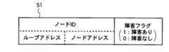
図5にIDパケットのフォーマットを示す。IDパケットはループアドレスとノードアドレスから構成されるノードID、および障害フラグのフィールドを含む。障害フラグは“1”か“0”の値をとり、“1”は障害があることを示し、“0”は障害がないことを示すものとする。
また、最下流ノードでないノードの制御手段は、監視信号の出力が“1”であれば、自ノードの直上のノードもしくは直上の伝送路において障害は発生していないと判断し、自ノードのIDパケットは送出せずに、受信したIDパケットの中継動作をする。この場合、監視信号の出力が“0”であるのは、断線障害16の直下のノード111のみである。ノード111のノードIDは(1.1)であるので、制御手段1113はループアドレスが“1”、ノードアドレスが“1”、障害フラグが“1”のIDパケットを出力する。出力した前記IDパケットは送信手段1115により伝送路へ送出される。
【0055】
次に「調査フェーズ3」について説明する。「調査フェーズ3」では、最下流ノードが動作する。最下流ノードの制御手段は自ループの障害状況を判断し、自分のIDに依存した待機時間の終了後、判断した障害状況をIDパケットで送信する。最下流ノードの制御手段は、以下のケース1からケース3のいずれかのように自ループの障害状況判断を行う。
まずケース1を説明する。調査フェーズ1において監視信号の出力が“1”であった場合、自ノードの直上のノードもしくは直上の伝送路において障害は発生していない。この状況でIDパケットを受信した場合、IDパケット中に含まれるノードIDを持つノードの上流において障害が発生していると判断する。従って、受信したIDパケットと同じIDパケットを送信する。
【0056】
次にケース2を説明する。調査フェーズ1において監視信号の出力が“1”であった場合、自ノードの直上のノードもしくは直上の伝送路において障害は発生していない。この状況でIDパケットを受信しない場合、自ループにおいて障害は発生していないと判断する。よって、自ループに障害がないことを示すために、ループアドレスが“自ループのループアドレス”、障害フラグが“0”のIDパケットを送信する。ノードアドレスのフィールドは何でも良いがここでは“0”を送信するものとしておく。
【0057】
最後にケース3を説明する。調査フェーズ1において監視信号の出力が“0”であった場合、自ノードの直上のノードもしくは直上の伝送路において障害が発生していると判断する。よってループアドレスが“自ノードのループアドレス”、ノードアドレスが“自ノードのノードアドレス”、障害フラグが“1”のIDパケットを送信する。
【0058】
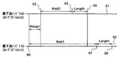
なお、前記“自分のIDに依存した待機時間”は、各最下流ノードの送信するIDパケットが共通伝達経路15において衝突しないように定めれば良い。そのような待機時間“Wait”の例として、各ループの最下流ノードが自ループの障害状況判断を完了する時刻の時間差の中で最大のものをMargin、IDパケットを送信開始してから送信終了までの時間をLength、IDパケットを送信する最下流ノードのループアドレスをLoop_Adr、とすると
Wait=(Margin+Length)×Loop_Adr・・・(数1)
のようなものが挙げられる。最下流ノードでの待ち時間を(数1)のようにすれば、各最下流ノードの送信するIDパケットが共通伝達経路15において衝突しないということを図6を参照しながら説明する。以下ではループアドレスは負でない整数であるとする。図6において、61はループアドレスが“0”である最下流ノード100の時間軸であり、62はループアドレスが“1”である最下流ノード110の時間軸である。63は最下流ノード100が自ループの障害状況判断を完了する時刻であり、64は最下流ノード100がIDパケット送出を開始する時刻であり、65は最下流ノード100がIDパケット送出を終了する時刻である。66は最下流ノード110が自ループの障害状況判断を完了する時刻であり、67は最下流ノード110がIDパケット送出を開始する時刻であり、68は最下流ノード110がIDパケット送出を終了する時刻である。また、最下流ノード100の待ち時間をWait0、最下流ノード110の待ち時間をWait1とする。最下流ノード110が自ループの障害状況判断を完了した後で最下流ノード100が自ループの障害状況判断を完了し、その時刻の時間差が最大となる(Marginに等しくなる)場合において最下流ノード100のIDパケットと最下流ノード110のIDパケットが共通伝達経路15において衝突しなければ良い。そのためには時刻65より時刻67が後になれば良い。この時、図6から
【0059】
Margin+Wait0+Length<Wait1・・・・(数2)
【0060】
が導かれる。(数2)より
Wait1−Wait0>Margin+Length・・・・(数3)
【0061】
が導かれる。(数3)より、最下流ノード110の待ち時間と110の次にIDパケットを送出する最下流ノード110の待ち時間の時間差が、“Margin+Length”より大きければ良いことが分かる。よってこのことから(数1)が導かれる。なお、前記“Margin”は各ループの伝送遅延や通知信号による障害発生の検出に必要な時間などを考慮して大きめに設定することが望ましい。
【0062】
以上のようにして、全最下流ノードが自ループの障害状況を判断し、IDパケットを時分割で送信する。本実施の形態の場合、最下流ノード100はケース2のように判断し、ループアドレスが“0”、ノードアドレスが“0”、障害フラグが“0”(障害フラグ=“0”は障害がないことを意味する)のIDパケット180を送信する。最下流ノード110はケース1のように判断し、ループアドレスが“1”、ノードアドレスが“1”、障害フラグが“1”(障害フラグ=“1”は障害があることを意味する)のIDパケット181を送信する。最下流ノード120はケース2のように判断し、ループアドレスが“2”、ノードアドレスが“0”、障害フラグが“0”のIDパケット182を送信する。
【0063】
次に「特定フェーズ」について説明する。ノード100,101,112,120,121は最下流ノードが送信した前記各IDパケットを受信し、ループ0および2には障害が発生しておらず、ループ1のノード(1.1)の直上において障害が発生していることを知る。断線障害16の下流に位置するノード111は、最下流ノードが送信した前記各IDパケットを受信しないが、「調査フェーズ1」において監視信号の値が“0”であったことから、自ノードの直上、つまりループ1のノード(1.1)の直上において障害が発生していることを知る。断線障害16の下流に位置するノード110も、最下流ノードが送信した前記各IDパケットを受信しないが、ノード111が送信したIDパケットによりループ1のノード(1.1)の直上において障害が発生していることを知る。
【0064】
次に「回復フェーズ」について説明する。以上のように、最下流ノードが送信したIDパケットにより障害の箇所が特定できると、必要により障害回復動作を行う。本実施の形態で示すネットワークでは、断線およびノード故障といった障害が発生したループ中のノードは正常に通信が行えなくなるが、障害が発生していないループ中のノードは正常に通信が行える。よって、自ループにおいて障害が発生していると判断したノード110,111,および112は、以降の通信動作を停止してネットワークシステムから離脱し、正常なループのノード100,101,120,および121のみでネットワークを再構築して障害の回復を行うものとする。マスタノード101は障害箇所の特定が完了すると特定の信号パターンの送出を再開し、ネットワークは通常の動作に復帰する。
以上のようにして、図2に示すようにノード111とノード112の間で伝送路の断線障害16が発生した場合に、障害箇所の検出および障害ループのネットワークシステムからの離脱が行われ障害が回復される。
【0065】
以下では、図3に示すようにノード101においてノード障害17が発生した場合の障害箇所特定方法の詳細を説明する。断線障害の場合と同様に、まず「検出フェーズ」について説明する。ここでいうノード障害とは故障によりノードが信号を送信および中継をしなくなった場合を想定する。マスタノードのノード障害17により、ノード100,110,111,112,120,および121は特定の信号パターンを受信しなくなる。従ってノード100の検出手段1001、ノード110の検出手段1101、ノード111の検出手段1111、ノード112の検出手段1121、ノード120の検出手段1201およびノード121の検出手段1211は、特定の信号パターンを受信しなくなって一定時間以上経過すると、未検出信号を出力する。ノード100の制御手段1003,ノード110の制御手段1103,ノード111の制御手段1113,ノード112の制御手段1123,ノード120の制御手段1203,およびノード121の制御手段1213は、未検出信号により障害の発生を検出する。この時、ノード100の信号監視手段1002,ノード110の信号監視手段1102,ノード111の信号監視手段1112,ノード112の信号監視手段1122,ノード120の信号監視手段1202,およびノード121の信号監視手段1212は、伝送路上を伝送される信号が存在しないので監視信号として“0”を出力している。
【0066】
次に「障害発生通知フェーズ」について説明する。ノード100の制御手段1003,ノード110の制御手段1103,ノード111の制御手段1113,ノード112の制御手段1123,ノード120の制御手段1203,およびノード121の制御手段1213は、未検出信号により障害の発生を検出すると、監視信号が“0”であるので断線障害の時と同様に通知信号を出力する。この場合、既に故障ノード101を除く全ノードが障害の発生を検出しているので、通知信号により障害の発生を検出するノードはない。以上により、故障ノード101を除くネットワーク中の全ノードが障害の発生を検出する。
【0067】
次に「調査フェーズ1」について説明する。断線障害の時と同様に、「障害発生通知フェーズ」の後、制御手段は特定信号を送出する。故障ノード101を除く全ノードの制御手段が障害を検出して特定信号を送出すると、それぞれのノードの送信手段により特定信号が伝送路へと送出される。故障ノード101を除く全ノードが特定信号を送出すると、ノード障害17の直下のノード100以外のノードにおいて、特定信号によって信号監視手段が伝送路上の信号の存在を検出し、値が“1”の監視信号を出力する。ノード障害17の直下のノード100においては、ノード障害17により信号監視手段は信号の喪失を検出したままであり、監視信号の出力は“0”のままである。本フェーズにおいて、監視信号の出力が“0”であったノード100は、障害の発生箇所が自ノードの直上であると知る。
【0068】
次に「調査フェーズ2」について説明する。断線障害の時と同様に、「調査フェーズ2」では最下流ノード以外のノードが動作する。この場合、故障ノード101と最下流ノードを除いたノード、つまりノード111,112,および121のいずれにおいても監視信号の出力は“1”であるので、最下流ノードでないノードのいずれからもIDパケットは出力されない。
【0069】
次に「調査フェーズ3」について説明する。断線障害の時と同様に、「調査フェーズ3」では最下流ノードが動作する。最下流ノードの制御手段は自ループの障害状況を判断し、自分のIDに依存した待機時間の終了後、判断した障害状況をIDパケットで送信する。最下流ノードの制御手段の自ループの障害状況判断は、断線障害の時と同様に行う。図3のようにノード障害17が発生した場合、最下流ノード100はケース3のように判断し、ループアドレスが“0”、ノードアドレスが“0”、障害フラグが“1”(障害フラグ=“1”は障害があることを意味する)のIDパケット190を送信する。最下流ノード110はケース2のように判断し、ループアドレスが“1”、ノードアドレスが“0”、障害フラグが“0”(障害フラグ=“0”は障害がないことを意味する)のIDパケット191を送信する。最下流ノード120はケース2のように判断し、ループアドレスが“2”、ノードアドレスが“0”、障害フラグが“0”のIDパケット192を送信する。
【0070】
次に「特定フェーズ」について説明する。ノード110,111,112,120,121は最下流ノードが送信した前記各IDパケットを受信し、ループ1および2には障害が発生しておらず、ループ0のノード(0.0)の直上において障害が発生していることを知る。ノード障害17の下流に位置するノード100は、最下流ノードが送信した前記各IDパケットを受信しないが、「調査フェーズ1」において監視信号の値が“0”であったことから、自ノードの直上、つまりループ0のノード(0.0)の直上において障害が発生していることを知る。
【0071】
次に「回復フェーズ」について説明する。以上のように、最下流ノードが送信したIDパケットにより障害の箇所が特定できると、断線障害の時と同様に、必要により障害回復動作を行う。ノード障害17が発生した場合は、自ループにおいて障害が発生していると判断したノード100は、以降の通信動作を停止してネットワークシステムから離脱する。本実施の形態で示すネットワークでは、断線およびノード故障といった障害が発生したループ中のノードは正常に通信が行えなくなるが、障害が発生していないループ中のノードは正常に通信が行える。よってノード障害17のように障害が発生した箇所がマスタノードが含まれるループであった場合には、正常に通信を行えるループ中のノードから代替マスタノードを選出する。障害が発生した箇所がマスタノードが含まれるループか否かは、記憶手段に記憶してあるマスタノードのノードID(0.1)から判断する。この場合は故障発生箇所がループ0であり、マスタノードのループアドレスが0であるのでマスタノードが含まれるループの障害と判断できる。
【0072】
以下では、代替マスタノードの選出について説明する。障害が発生していないループ中のスレーブノード110,111,112,120,121は、マスタノードが含まれるループの障害を検出すると、自分のノードIDに依存した待ち時間だけ待つ。前記待ち時間が終了したノードは代替マスタノードとして動作し、特定の信号パターンの送出を開始する。他のノードは、前記特定の信号パターンの受信によりマスタノードの復帰を知り、スレーブノードとして動作する。なお、代替マスタノードとして動作しようとするノードは、特定の信号パターンを送出する代りに、自ノードが代替マスタノードとして動作することを宣言するパケットを送出しても良い。その場合には他のノードは、前記宣言するパケットの受信によりマスタノードの復帰を検出してスレーブノードとして動作すれば良い。
【0073】
なお、前記“自分のノードIDに依存した待ち時間”を本実施の形態では一定の時間“T”とノードIDとの積(自分のノードID*T)としておく。ここで“T”は一定時間である。ノードIDは(1.0)であれば10、(2.1)であれば21、のように扱う。あるノードID(例えば整数K)を持つ代替マスタノードが送出した特定の信号パターンが正常ループ中の全ノードに伝送された後に、前記ノードIDより大きいノードID(例えばKより大きい整数)を持つノードの待ち時間が終了するように、一定時間“T”を選ぶ必要がある。
【0074】
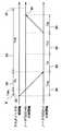
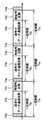
図7および図8を参照しながらそのような時間“T”が満たすべき条件を説明する。以下ではノードのIDは負でない整数であるとし、ノードが特定の信号パターンを受信しなくなってから未検出信号を出力するまでの一定時間をTwとする。図7において71はマスタノードであり、72はノードIDがKのノードであり、73はノードIDがJのノードであり、74はマスタノード71からノード72への経路であり、75はマスタノード71からノード73への経路であり、76はノード73からノード72への経路である。また、経路74の伝送遅延時間はTmkであり、経路75の伝送遅延時間はTmjであり、経路76の伝送遅延時間はTjkであるとする。
【0075】
また図8において81はマスタノードが含まれるループに障害発生後、最初の特定の信号パターン送出予定時刻であり、82はマスタノード71からノード72への伝送遅延時間(Tmk)であり、83はノード72の待ち時間(T*K)であり、84はマスタノード71からノード73への伝送遅延時間(Tmj)であり、85はノード73の待ち時間(T*J)であり、86はノード73からノード72への伝送遅延時間(Tjk)であり、87はノード72が代替マスタノードとして特定の信号パターンの送出を開始する予定の時刻であり、88はノード73が代替マスタノードとなり送出した特定の信号パターンがノード72に到着する時刻である。また、89は検出フェーズ、障害発生通知フェーズ、調査フェーズ1、調査フェーズ2、調査フェーズ3、および特定フェーズの処理に要する時間(Tn)である。
【0076】
ある時刻にマスタノードが含まれるループに障害が発生した場合を考える。マスタノードが含まれるループに障害発生後、最初の特定の信号パターン送出予定時刻を時刻0とする(図8の81に相当する。ネットワークが正常に動作していればマスタノードが送出した特定の信号パターンは一定時間間隔で全ノードにより受信される)。マスタノード71から一定時間間隔で送信されてくるはずの特定の信号パターンの喪失により、時刻“Tmk+Tw”にノード72はネットワークの障害を検出し、障害箇所の特定が完了する時刻“Tmk+Tn”にはマスタノード71の故障を検出する。同様にして時刻“Tmj+Tw”にノード73はネットワークの障害を検出し、障害箇所の特定が完了する時刻“Tmj+Tn”にはマスタノード71の故障を検出する。ノード72の待ち時間はT*K(図8の83に相当)であり、ノード73の待ち時間はT*J(図8の85に相当)である。JがKより小さい(ノードID=Jを持つノード73の方が優先度が高い)場合を考えると、ノード73がT*Jの待ち時間(図8の85に相当)の後に送出した特定の信号パターンが、ノード72の待ち時間が終了するまでにノード72に到着し、マスタノードの復帰を検出できれば良い。図8において、ノード72の待ち時間が終了するのは87であり、ノード73が送出した特定の信号パターンがノード72に到着するのは88である。
【0077】
よって
Tmj+Tn+T*J+Tjk<Tmk+Tn+T*K・・・・(数4)
を満たす“T”を選べばよいと分かる。(数4)を整理すると
T>(Tmj+Tjk−Tmk)/(K−J)・・・・(数5)
【0078】
が導かれるが(数5)において右辺が最大となるのはK=J+1の場合である。よって
T>Tmj+Tjk−Tmk・・・・(数6)
【0079】
が導かれる。(数6)の右辺が最大となるのはTmjとTjkが最も大きく、Tmkが最も小さい場合である。よって一般的には、ノード間の伝送遅延時間のうち最も大きいものをT1、2番目に大きい伝送遅延時間(T1と等しい場合もありえる)をT2、最少のものをTmとれば、“T1+T2−Tm”より大きい値を“T”として採用すれば十分である。また、この時
2*T1>T1+T2−Tm>Tmj+Tjk−Tmk・・・・(数7)
【0080】
が成り立つので、(数6)を満たす“T”の簡単な例として“ノード間の伝送遅延時間の最大値の2倍”が挙げられる。
【0081】
以上のように“T”として“ノード間の伝送遅延時間の最大値の2倍”を採用すれば、ノードID=Kを持つ代替マスタノードが送出した特定の信号パターンがネットワーク中の全ノードに伝送された後に、ノードIDがKより大きいノードの待ち時間が終了するため、ノードIDがKより大きいノードは特定の信号パターン送出を開始できなくなる。よってノードID=Kを持つノードは、代替マスタノードとして動作を開始する前に、ノードID=Kを持つノードより優先度の高い他の代替マスタノード候補のノードがネットワーク中に存在しないことを知ることができる。
【0082】
図3のネットワークにおいて、障害が発生していないループに属するスレーブノード中で待ち時間が最も短いノード、つまり最少のノードIDを持つノードはスレーブノード110である。よって最初に特定の信号パターン送出を開始するのはスレーブノード110であり、“T*10”の待ち時間後に代替マスタノードとして特定の信号パターン送出を開始する。
【0083】
次に待ち時間が短いスレーブノードは111であるが、スレーブノード111は、待ち時間が終了して特定の信号パターンの送出を開始する前にスレーブノード110が送出した特定の信号パターンを受信するので、通常のスレーブノードとしての動作に復帰する。他のスレーブノード112,120,121についても同様に、通常のスレーブノードとしての動作に復帰する。ノード110は記憶手段1104に自ノードがマスタノードであると設定し、それ以降マスタノードとして動作する。
【0084】
以上のようにして、図3に示すようにノード障害17が発生した場合に、障害が発生したループ中のノードのネットワークからの離脱、および代替マスタノードの選出がなされ、正常なループ中のノード110,111,112,120,121のみでネットワークが再構築されて障害の回復が行われる。
【0085】
なお、本実施の形態の説明においては代替マスタノード選出の際のノードIDに依存した待ち時間を「自分のノードID*T」としたが、待ち時間の例はこの限りではない。ノードIDにより優先度が決定されて優先度の高いノードから順に代替マスタノードの候補となり、ある優先度を持つノードが代替マスタノードとして動作を開始したことが全ノードに伝達される前に、前記優先度より低い優先度のノードが代替マスタノードとして動作を開始することがないのであればどのような“T”を採用しても良い。例えば「一定時間+自分のノードID*自分のノードID*T」等としてもよい。
【0086】
また、本実施の形態の説明においては代替マスタノード選出の際の優先度を決定する要素としてノードIDを用いたが、ノードIDに限らずあらかじめ決められたマスタノードになりうる優先度の値をノードIDの代りに用いても同様にして代替マスタノードを選出することが可能である。
【0087】
また、障害の回復を早くするために、“第一の優先度”つまりネットワークシステムの全ノード中で最も高い優先度を持つノードの待ち時間を“0”とすることで、第一の優先度を持つノードが代替マスタノードの選出の必要性があることを認識するとすぐに代替マスタノードとして動作するようにしても良い。またこの時、第一の優先度を持つノードがすぐにマスタノードとして動作し、通常のデータ通信を再開できるようにするために、第一の優先度を持つノードがあらかじめマスタノードの持つ通信管理情報を保持しても良い。ここでいう通信管理情報は例えばノード間で設定されているチャネル情報(送信ノードID、受信ノードID)、帯域情報、等があげられる。
【0088】
なお、ネットワークによってはある特定の条件を満たすノードしか代替マスタノードになりえない場合がある。そのようなネットワークにおいては前記特定の条件を満たすノードのみが代替マスタノードの候補になるようにすれば良い。
【0089】
また、本実施の形態の説明においては、全スレーブノードが代替マスタノードの候補として動作しうる機能を備えている場合を例にとり説明したが、この限りでなくても良い。例えば、ノード100、110、120のみが代替マスタノードの候補として動作しうる機能を備えており、他のスレーブノード111、112、121は代替マスタノードの候補として動作しうる機能を備えていない場合等も同様にして代替マスタノードを選出することが可能である。
【0090】
上記のように一部のスレーブノードのみに代替マスタノードの候補として動作させるためには、例えば次のようにすれば良い。あらかじめ、代替マスタノードの候補として動作する機能があるスレーブノードはノードIDのうち“ノードアドレス”の部分を“0”にしておく。マスタノードの故障を検知したスレーブノードは、自分のノードアドレスが“0”であるならば代替マスタノードの候補として動作し、ノードアドレスが“0”でなければ代替マスタノードの候補にはならないようにする。こうしておけば図1の場合であれば、スレーブノード100、110、120のみが代替マスタノードの候補として動作するようになる。あるいは次のようにしても良い。代替マスタノードの候補として動作しても良いか否かを設定するフラグを設けておき、代替マスタノードの候補として動作して良いスレーブノードのみあらかじめ前記フラグを“1”に設定しておく。マスタノードの故障を検出したスレーブノードは前記フラグが“1”なら代替マスタノードの候補として動作し、“0”なら代替マスタノードの候補として動作しない。
【0091】
また、上記のように一部のスレーブノードのみが代替マスタノードの候補となる場合、前記ノード間の伝送遅延時間は、マスタノードもしくは前記代替マスタノードの候補となるスレーブノード間だけを考慮して代替マスタノード選出の際の待ち時間における“T”を決定して良い。
【0092】
また、ノードIDの代りにノードIDの一部のビット列を用いても良い。例えば、図9に示すように、全6ビットで構成されるノードID(91)のうち、上位3ビット(92)がループに固有の“ループアドレス”で構成され、下位3ビット(93)が同じループ中の異なるノードを識別するための“ノードアドレス”で構成される場合を考える。このようにループアドレスがノードID中に含まれている場合は、代替マスタノードになりうるノードをループ中で1つに限定し(例えばループ中でノードの出力が共通伝達経路15に直接接続しているノードのみが代替マスタノードになることができる等)、待ち時間を「自分のノードのループアドレス*T」としても良い。
なお、マスタノードのノードIDをスレーブノードが知る必要のあるネットワークにおいては、代替マスタノードは最大の待ち時間の経過後に、新しいマスタノードのノードIDを知らせるために、自分のノードIDを全ノードに通知しても良い。
【0093】
また、本実施の形態の説明においては、障害箇所の特定方法および代替マスタノードの選出方法を図1に示した構成を持つネットワークを例にとり説明したが、ネットワークの構成はこれに限られるものではなく、ネットワーク中のループの数、ノードの数、マスタノードの位置等は任意に構成できることは言うまでもない。例えば、単一のノードから構成されるループがあっても良い。また、本実施の形態で説明した代替マスタノードの選出方法に関しては、ループとバスの混在型トポロジを持つネットワークだけに限られるものでもなく、バス型、ループ型、スター型、ツリー型等さまざまなトポロジのネットワークに適用することが可能である。
【0094】
また、上記実施の形態において、特定の信号パターンの受信時刻の間隔を“Ti”とするとTiは一定でなくても良い。例えばTiがある最大値Tmax以内の可変値をとる場合には、Tmaxより長い時間、特定の信号パターンを受信しなければ障害が発生していると判断すれば良い。また、Tiは可変値であっても次の特定の信号パターンの受信予定時刻がわかっている場合には、受信予定時刻に特定の信号パターンを受信しなければ障害が発生していると判断すれば良い。
【0095】
また、特定の信号パターンは、通常伝送されるデータや各種信号と区別できるものであれば何でも良い。例えば、マスタノードと同期したクロック再生を実現するための同期用信号であっても良く、ネットワーク上で他の伝送されるデータと区別できる特殊な信号パターンであっても良く、あらかじめ決めておいた特定のフォーマットのパケットであっても良い。例えば特定の信号パターンがマスタノードと同期したクロック再生を実現するための同期用信号であった場合は、検出手段をPLL(Phase Locked Loop)回路とし、未検出信号をPLLのロック外れ信号として実現しても良い。あるいは、データ送信を許可されるノードのノードIDである送信ノードIDと送信されたデータを受信すべきノードのノードIDである受信ノードIDを含む“通信制御パケット”をマスタノードが一定時間間隔もしくは一定時間以内の可変の間隔で送出し、前記“通信制御パケット”によってノードが送信権および受信権を得るネットワークでは、前記特定の信号パターンは、“通信制御パケット”であっても良い。もしくは、マスタノードが固定長のフレームを一定周期(44.1KHz等)で巡回させて伝送を行う形式のネットワークにおいては、前記特定の信号パターンは前記固定長のフレームであっても良い。
【0096】
また、最下流ノードがIDパケットを送信する方法は、各最下流ノードが送信したIDパケットが衝突して受信不能にならないのであれば、時分割で送信する方法に限らない。例えば各最下流ノードが異なる周波数で送信することにより衝突を回避しても良い。
【0097】
なお、以上に説明した方法では、最下流ノードのノード障害および最下流ノードの直下の断線障害は検出できない。よって、最下流ノードのノード障害および最下流ノードの直下の断線障害を検出するためには、通常の通信状態においてマスタノード101が定期的に各最下流ノードに対して問合せを行い、前記問合せに対して各最下流ノードが応答を返すようにすれば良い。各最下流ノードへの問合せは、対象となる最下流ノードを指定した問合せパケットをマスタノードが送出すればよい。各最下流ノードは自ノード宛の問合せパケットを受信すれば応答を応答パケットで送出すればよい。マスタノードはある最下流ノードからの応答パケットを受信しない場合には、前記最下流ノードのノード障害もしくは前記最下流ノードの直下の断線障害が発生したと判断する。さらに障害ループを離脱するならば、マスタノードは、ネットワークから離脱することを指示する離脱通知パケットを送出する。離脱通知パケット中は離脱すべき対象のループのループアドレスを含む。前記離脱通知パケットを受信したノードは、自ループアドレスと前記離脱通知パケット中のループアドレスが一致すれば、ネットワークシステムから離脱する。
【0098】
なお、通知信号は、他のノードが障害の発生を検出できる信号であれば何でも良く、特定の信号パターンの受信を妨害する信号には限らない。例えば、通知信号は通常伝送に用いる信号と周波数の異なった信号にしておき、全ノードはこのような通知信号を送信する手段を備える構成とし、検出手段がこのような通知信号の受信を検出したときに未検出信号と同様の信号を出力するような構成としても良い。
【0099】
また、特定信号は、「調査フェーズ1」において特定信号の未受信によりノードが自ノードの直上において障害が発生しているか否かを判断できる信号であれば何でも良く、一定時間連続したHighレベルの信号には限らない。例えば連続したHighレベルと連続したLowレベルが一定時間毎に繰返されるような信号であっても良い。
【0100】
なお、ここまでに説明した障害箇所特定方法では、障害が発生すると全ノードが障害の発生を検出して障害箇所検出の処理を行う。よって障害箇所検出処理を行って、障害箇所を検出し回復するまでは通常通信が行われない。例えば通常通信において映像・音声等の等時性を要求されるデータの通信が行われていた場合、障害の発生により通信が中断され、音声や映像データが欠落し、音飛びや映像の欠落といった事が発生する。よって、障害が発生した場合でも通常の通信が妨げられないようにするために、以下で説明するように“無信号時間”を設けても良い。図10に示すように通常通信において伝送路上に信号が伝送されない“無信号時間”を設ける。図10において、10aは特定の信号パターンが通信される時間、10bは通常のデータ通信が行われる時間、10cは無信号時間である。図10に示すように無信号時間は一定周期毎に訪れるので、各ノードは信号を受信しなくなっても無信号時間の始まるタイミングと終わるタイミングを認識できる。特定の信号パターンの未受信により障害発生を検出すれば、ノードは前記無信号時間を利用して、通知信号、特定信号、IDパケット等の各種信号やパケットを送受信して障害箇所の特定および障害回復を行う。なお、無信号時間の訪れるタイミングが各ノードで既知であるならば、無信号時間は一定周期毎に訪れるものに限らなくてもよい。
【0101】
なお、正常動作時のネットワークの構成状態を記憶しておいて、障害発生箇所を特定する際に前記正常動作時のネットワークの構成状態を利用しても良い。例えば、ループ内のノード接続順がランダムであり、従ってループ内において各ノードのノードIDがどういう順番で並んでいるかが不明である場合には、障害の発生箇所の直下のノードのノードIDを特定するだけでは不十分な場合がある。そのような時は、正常動作時のネットワークの構成状態(接続されているノードのノードIDの順番)を記憶しておき、障害の発生箇所の直下のノードのノードIDから、障害発生箇所がループ中において上流から何番めと何番めに位置するノードの間であるかを特定できる。
【0102】
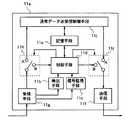
また、これまで述べてきたノードの構成に加えて、図11に示すように各ノード11aが通常データ送受信制御手段11jと、スイッチ11hおよびスイッチ11iを備えても良い。ここで、通常データ送受信制御手段11jは通常時のデータ送受信を制御する。スイッチ11hはA側に接続すると通常データ送受信制御手段11jと受信手段11gを接続し、B側に接続すると制御手段11dと受信手段11gを接続する。スイッチ11iはA側に接続すると通常データ送受信制御手段11jと送信手段11fを接続し、B側に接続すると制御手段11dと送信手段11fを接続する。通常時にはスイッチ11hおよびスイッチ11iが通常データ送受信制御手段11jと接続(A側に接続)し、通常のデータ通信が行われる。障害発生時にはスイッチ11hおよびスイッチ11iが制御手段11dと接続(B側に接続)し、障害箇所検出用の信号の送受信が行われる。スイッチの制御は制御手段11dが行う。制御手段は障害の発生を検出するとスイッチをA側からB側に切換え、通常のデータ送受信を開始する前にスイッチをB側からA側に切換える。このようにノードを構成しても本実施の形態で説明した障害箇所の特定動作および代替マスタノードの選出動作が可能であることはいうまでもない。
【0103】
また、故障したノードは、自ノードの故障を認識すると受信した信号を加工せずに通過させる“バイパスモード”で動作しても良い。ノードがバイパスモードを持ち、なんらかのノードの故障によりそのノードが自ノードのデータを送信したり他ノードからのデータを受信することができなくなった場合でもバイパスモードで動作すれば、故障ノードと同じループに属する他の正常なノードはネットワークシステムから離脱しなくてよくなる。このようにノードがバイパスモードを持つ場合でも本実施の形態で説明した障害箇所の特定動作および代替マスタノードの選出動作は同様にして実施可能である。
【0104】
なお、本実施の形態で説明した代替マスタノード選出方法は、代替マスタノードの選出だけを実施することも可能である。例えば全ノードが共通伝達経路に直接接続されている、いわゆるバス型ネットワーク(図1に示すネットワークにおいて各ループに属するノードの数がそれぞれ1台である場合等もバス型ネットワークになる)であれば、特定の信号パターンの未受信でマスタノードの障害と判断し、本実施の形態で説明した代替マスタノードの選出動作を各ノードが行っても良い。また単一ループ型のネットワークにおいても、マスタノード故障時にはマスタノードが上記のように“バイパスモード”で動作すれば、本実施の形態で説明した代替マスタノード選出方法により代替マスタノードを選出してネットワークシステム全体の動作停止を回避して動作を続けることが可能である。
【0105】
【発明の効果】
以上のように本発明(請求項1)によれば、複数のノードが伝送路により接続され、前記伝送路に一定時間以内ごとに特定の信号パターンが伝送されるネットワークシステムであって、前記各ノードが、前記伝送路を伝送される信号の有無を検出する信号監視手段と、前記特定の信号パターンの受信を検出し該特定の信号パターンを所定時間以上受信しなかったときに未検出信号を出力する検出手段とを備え、前記検出手段により出力する前記未検出信号によりネットワークシステムの障害発生を検出し、障害発生を検出した前記ノードが、通知信号により障害の発生を隣接するノードに通知し、前記通知信号によりネットワークシステム中の各ノードが障害の発生を検出し、障害発生を検出したノードは特定信号を隣接ノードへ送信し、特定信号の未受信により自ノードの上流で障害が発生していると判断すると、判断した障害箇所を示すための信号をノード間で送受信することにより、ネットワークシステムの障害箇所を特定する構成としたから、ループ接続された複数のノードで構成される少なくとも1つのループ、及び、単一のノードまたはループ接続された複数のノードで構成される1つ以上のループが共通伝達経路に直接接続されて構成されるネットワークシステムにおいても、障害の発生を検出し、障害の発生箇所を特定できるネットワークシステムを実現できる効果がある。
【0106】
また、本発明(請求項2)によれば、伝送路によりループ接続された複数のノードで構成される少なくとも1つのループ、および、単一のノードまたは伝送路によりループ接続された複数のノードで構成される1つ以上のループが、一つ以上の入力部と一つ以上の出力部を有し一つの入力部より入力する信号が分岐され全ての出力部より出力される共通伝達経路に直接接続され、前記複数のループのいずれかに含まれた1つのノードがマスタノードとなり、前記マスタノードとなるノード以外のノードがスレーブノードとなり、さらに前記各ループにおいて最下流のノードが前記各ループの最下流ノードとなり、前記伝送路に一定時間以内ごとに特定の信号パターンが伝送されるネットワークシステムであって、前記各ノードが、前記伝送路を伝送される信号の有無を検出し監視信号を出力する信号監視手段と、前記特定の信号パターンの受信を検出し該特定の信号パターン所定時間以上受信しなかったときに未検出信号を出力する検出手段とを備え、前記検出手段より出力する未検出信号によりネットワークシステムの障害発生を検出し、障害発生を検出した前記ノードが、通知信号により障害の発生を隣接するノードに通知し、前記通知信号によりネットワークシステム中の各ノードが障害の発生を検出し、前記各ループのそれぞれにおいて、障害発生を検出した前記ノードが特定信号を隣接ノードへ送信し、前記信号監視手段が出力する前記監視信号により前記特定信号の未受信を検出したノードが、自ノードの上流において障害が発生していると判断して自ループの障害箇所をノードを特定する情報を含むIDパケットで前記最下流ノードに送信し、複数の前記各最下流ノードが、前記IDパケットおよび前記監視信号により自ループの障害箇所を判断し、判断した前記自ループの障害箇所をデータの衝突がないようにIDパケットで送信し、障害発生を検出した前記ノード,および前記通知信号により障害の発生を検出したネットワークシステム中の各ノードが、前記監視信号と前記IDパケットに基づきネットワークシステムの障害箇所を特定する構成としたから、ループ接続された複数のノードで構成される少なくとも1つのループ、及び、単一のノードまたはループ接続された複数のノードで構成される1つ以上のループが共通伝達経路に直接接続されて構成されるネットワークシステムにおいても、障害の発生を検出し、障害の発生箇所を特定できるネットワークシステムを実現できる効果がある。
【0107】
また、本発明(請求項3)によれば、請求項2記載のネットワークシステムにおいて、正常動作時に、マスタノードが各最下流ノード宛に問合せパケットを送出し、前記各最下流ノードが自ノード宛の前記問合せパケットを受信すると応答パケットを送出し、マスタノードが前記応答パケットの受信の有無により障害の発生を検出する構成としたから、ループ接続された複数のノードで構成される少なくとも1つのループ、及び、単一のノードまたはループ接続された複数のノードで構成される1つ以上のループが共通伝達経路に直接接続されて構成されるネットワークシステムにおいて、最下流ノードのノード障害,最下流ノードの直下の断線障害の発生を検出できる効果がある。
【0108】
また、本発明(請求項9)によれば、請求項1または2記載のネットワークシステムにおいて、ネットワーク中には1つのマスタノードと1つ以上のスレーブノードが存在し、前記マスタノードおよび前記スレーブノードにはノードを特定するための固有のノードIDが割当てられており、前記スレーブノード中に代替マスタノードとなることのできる候補ノードが少なくとも1つ存在し、正常に通信可能である前記候補ノードが、特定したネットワークシステムの障害箇所に基づき代替マスタノードの選出が必要であると判断すれば、前記固有のノードIDにより決定される待ち時間だけ待ってから前記代替マスタノードとして動作を開始し、正常に通信可能である前記候補ノードが、前記待ち時間だけ待つ間に前記マスタノードの復帰を検出すれば、前記スレーブノードとしての動作に復帰することにより、1つ以上の前記候補ノード群から1つの前記代替マスタノードを選出し、前記固有のノードIDにより優先度が決定され、ある前記優先度Kを持つ前記候補ノードが前記代替マスタノードとして動作を開始したことが全ノードに伝達されるのに必要な時間が経過した後に、前記優先度Kより低い優先度を持つ前記候補ノードの前記待ち時間が終了する構成としたから、ループ接続された複数のノードで構成される少なくとも1つのループ、及び、単一のノードまたはループ接続された複数のノードで構成される1つ以上のループが共通伝達経路に直接接続されて構成されるネットワークシステムにおいても、障害の発生を検出し、障害の発生箇所を特定し、マスタノード故障の場合には代替マスタノードをスレーブノード中から自動的に選出することによりマスタノードの故障によるネットワークシステム全体の動作停止を回避することのできるネットワークシステムを実現できる効果がある。
【0109】
また、本発明(請求項17)によれば、複数のノードが伝送路により接続され、前記伝送路に一定時間以内ごとに特定の信号パターンが伝送されるネットワークシステムにおいてネットワークシステムの障害箇所を特定する障害箇所特定方法であって、前記ノードが、前記特定の信号パターンを一定時間以上受信しないことからネットワークシステムの障害発生を検出し、障害発生を検出した前記ノードが、通知信号により障害の発生を隣接するノードに通知し、前記通知信号によりネットワークシステム中の各ノードが障害の発生を検出し、障害発生を検出したノードは特定信号を隣接ノードへ送信し、特定信号の未受信により自ノードの上流で障害が発生していると判断すると、判断した障害箇所を示す信号をノード間で送受信することにより、前記各ノードがネットワークシステムの障害箇所を特定するようにしたから、ループ接続された複数のノードで構成される少なくとも1つのループ、及び、単一のノードまたはループ接続された複数のノードで構成される1つ以上のループが共通伝達経路に直接接続されて構成されるネットワークシステムにおいても、障害の発生を検出し、障害の発生箇所を特定できる効果がある。
【0110】
また、本発明(請求項18)によれば、伝送路によりループ接続された複数のノードで構成される少なくとも1つのループ、および、単一のノードまたは伝送路によりループ接続された複数のノードで構成される1つ以上のループが、一つ以上の入力部と一つ以上の出力部を有し一つの入力部より入力する信号が分岐され全ての出力部より出力される共通伝達経路に直接接続され、前記複数のループのいずれかに含まれた1つのノードがマスタノードとなり、前記マスタノードとなるノード以外のノードがスレーブノードとなり、さらに前記各ループにおいて最下流のノードが前記各ループの最下流ノードとなり、前記伝送路に一定時間以内ごとに特定の信号パターンが伝送されるネットワークシステムにおいてネットワークシステムの障害箇所を特定する障害箇所特定方法であって、前記各ノードは、前記伝送路を伝送される信号の有無を検出し監視信号を出力し、前記ノードが、前記特定の信号パターンを一定時間以上受信しないことからネットワークシステムの障害発生を検出し、障害発生を検出した前記ノードが、通知信号により障害の発生を隣接するノードに通知し、前記通知信号によりネットワークシステム中の各ノードが障害の発生を検出し、前記各ループのそれぞれにおいて、障害発生を検出した前記ノードが、特定信号を隣接ノードへ送信し、前記特定信号の未受信により自ノードの上流において障害が発生していると判断して自ループの障害箇所をIDパケットで前記最下流ノードに送信し、複数の前記各最下流ノードが、前記IDパケットおよび前記監視信号により自ループの障害箇所を判断し、判断した前記自ループの障害箇所をデータの衝突がないようにIDパケットで送信し、障害発生を検出した前記ノード,および前記通知信号により障害の発生を検出したネットワークシステム中の各ノードが、前記監視信号と前記IDパケットに基づきネットワークシステムの障害箇所を特定するようにしたから、ループ接続された複数のノードで構成される少なくとも1つのループ、及び、単一のノードまたはループ接続された複数のノードで構成される1つ以上のループが共通伝達経路に直接接続されて構成されるネットワークシステムにおいて、障害の発生を検出し、障害の発生箇所を特定できる効果がある。
【図面の簡単な説明】
【図1】本発明の実施の形態1におけるネットワークシステムの構成を示す図である。
【図2】本発明の実施の形態1におけるネットワークシステムにおいて、断線障害16が発生した様子を示す図である。
【図3】本発明の実施の形態1におけるネットワークシステムにおいて、ノード障害17が発生した様子を示す図である。
【図4】本発明の実施の形態1における故障検出方法を説明する図である。
【図5】IDパケットの構成を示す図である。
【図6】Wait時間の説明をする図である。
【図7】本発明の実施の形態1における一定時間“T”の満たすべき条件を説明する図である。
【図8】本発明の実施の形態1における一定時間“T”の満たすべき条件を説明する図である。
【図9】本発明の実施の形態1におけるノードIDの構成を示す図である。
【図10】無信号時間を説明する図である。
【図11】スイッチを備えたノードの構成を示す図である。
【図12】従来例を説明する図である。
【図13】従来例の問題点を説明する図である。
【符号の説明】
100 スレーブノード
101 マスタノード
110 スレーブノード
111 スレーブノード
112 スレーブノード
120 スレーブノード
121 スレーブノード
13 伝送路
15 共通伝達経路
1001 ノード100の検出手段
1002 ノード100の信号監視手段
1003 ノード100の制御手段
1004 ノード100の記憶手段
1005 ノード100の送信手段
1006 ノード100の受信手段
1011 ノード101の検出手段
1012 ノード101の信号監視手段
1013 ノード101の制御手段
1014 ノード101の記憶手段
1015 ノード101の送信手段
1016 ノード101の受信手段
1101 ノード110の検出手段
1102 ノード110の信号監視手段
1103 ノード110の制御手段
1104 ノード110の記憶手段
1105 ノード110の送信手段
1106 ノード110の受信手段
1111 ノード111の検出手段
1112 ノード111の信号監視手段
1113 ノード111の制御手段
1114 ノード111の記憶手段
1115 ノード111の送信手段
1116 ノード111の受信手段
1121 ノード112の検出手段
1122 ノード112の信号監視手段
1123 ノード112の制御手段
1124 ノード112の記憶手段
1125 ノード112の送信手段
1126 ノード112の受信手段
1201 ノード120の検出手段
1202 ノード120の信号監視手段
1203 ノード120の制御手段
1204 ノード120の記憶手段
1205 ノード120の送信手段
1206 ノード120の受信手段
1211 ノード121の検出手段
1212 ノード121の信号監視手段
1213 ノード121の制御手段
1214 ノード121の記憶手段
1215 ノード121の送信手段
1216 ノード121の受信手段
16 ノード112とノード111の間の断線障害
17 ノード101のノード障害
180 断線障害16の発生によりノード100が送出するIDパケット
181 断線障害16の発生によりノード110が送出するIDパケット
182 断線障害16の発生によりノード120が送出するIDパケット
190 ノード障害17の発生によりノード100が送出するIDパケット
191 ノード障害17の発生によりノード110が送出するIDパケット
192 ノード障害17の発生によりノード120が送出するIDパケット
41 マスタノードが送出する特定の信号パターン
42 故障が発生した時刻
43 故障により受信されなかった特定の信号パターン
44 代替マスタノードの選出等による障害回復後、受信する特定の信号パターン
51 IDパケット
61 最下流ノード100の時間軸
62 最下流ノード110の時間軸
63 最下流ノード100が自ループの障害状況判断を完了する時刻
64 最下流ノード100がIDパケット送出を開始する時刻
65 最下流ノード100がIDパケット送出を終了する時刻
66 最下流ノード110が自ループの障害状況判断を完了する時刻
67 最下流ノード110がIDパケット送出を開始する時刻
68 最下流ノード110がIDパケット送出を終了する時刻
71 マスタノード
72 ノードIDがKのノード
73 ノードIDがJのノード
74 マスタノード71からノード72への経路
75 マスタノード71からノード73への経路
76 ノード73からノード72への経路
81 マスタノードの故障後、最初の特定の信号パターン送出予定時刻
82 マスタノード71からノード72への伝送遅延時間(Tmk)
83 ノード72の待ち時間(T*K)
84 マスタノード71からノード73への伝送遅延時間(Tmj)
85 ノード73の待ち時間(T*J)
86 ノード73からノード72への伝送遅延時間(Tjk)
87 ノード72が代替マスタノードとして特定の信号パターンの送出を開始する時刻
88 ノード73の特定の信号パターンがノード72に到着する時刻
89 検出フェーズ、障害発生通知フェーズ、調査フェーズ1、調査フェーズ
2、調査フェーズ3、および特定フェーズの処理に要する時間(Tn)
91 ノードID
92 ノードIDの上位3ビットから成るループアドレス
93 ノードIDの下位3ビットから成るノードアドレス
10a 特定の信号パターンが通信される時間
10b 通常のデータ通信が行われる時間
10c 無信号時間
11a スイッチを備えたノード
11b 検出手段
11c 信号監視手段
11d 制御手段
11e 記憶手段
11f 送信手段
11g 受信手段
11h スイッチ
11i スイッチ
11j 通常データ送受信制御手段
12a 主局
12b 端末局
12c 端末局
12d 端末局
12e 端末局
12f 回線[0001]
BACKGROUND OF THE INVENTION
The present invention relates to a network system comprising a master node and one or more slave nodes, wherein a specific signal pattern is transmitted by the master node, and the specific signal pattern is received by all nodes within a predetermined time. The present invention relates to a method for automatically selecting an alternative master node from among slave nodes in the event of a failure, a method for identifying a failure location such as a disconnection or a node failure and realizing failure recovery, and a network system capable of identifying the failure location and failure recovery. Is.
[0002]
[Prior art]
In a conventional network system in which a master node is necessary for data transmission, such as when there is a master node and a slave node in the network, and the master node arbitrates data transmission rights, a failure occurs in the master node Then, there was a problem that data communication could not be performed.
In addition, as a failure location detection method in a conventional network system, as disclosed in, for example, Japanese Patent Laid-Open No. 56-161742, in a loop network, when a carrier interruption continues for a certain time or more, a self-carrier is transmitted, There is a failure location detection method in which a master node can recognize that there is a failure before the slave node that sent this address by sending a response including its own node address on a self-carrier after a predetermined time.
[0003]
The failure location detection method disclosed in Japanese Patent Laid-Open No. 56-161742 will be described below with reference to FIG. FIG. 12 shows an example of a loop network. In FIG. 12, 12a is a main station, 12b, 12c, 12d and 12e are terminal stations, and 12f is a line. In a normal state, the
[0004]
Now, as shown in FIG. 12, if a line failure occurs between the
When each station detects a carrier interruption, it starts sending its own carrier after Ta time. Accordingly, the
[0005]
Therefore, the
[0006]
[Problems to be solved by the invention]
However, in the method disclosed in Japanese Patent Laid-Open No. 56-161742, if the network configuration is not a loop type, depending on the network configuration, even if the occurrence of a failure is detected by the above method, the occurrence of the failure The location cannot be identified.
For example, the network disclosed in Japanese Patent Application No. 10-113659 as shown in FIG. 13, that is, at least one loop composed of a plurality of nodes connected in a loop, and a single node or a loop connected. In the network system in which one or more loops composed of a plurality of nodes are directly connected to the common transmission path, when a disconnection failure occurs between the
[0007]
When a disconnection failure occurs, a carrier disconnection is detected at the
[0008]
When a node failure occurs in the
[0009]
In addition, depending on the network configuration, there is a network in which when the master node fails, an alternative master node can be selected to avoid the operation stop of the entire network. In such a network, the node that detected the occurrence of a failure is one in which the failure point is related to the master node, so selection of an alternative master node is necessary, or the failure point is related to the master node. Therefore, it is necessary to determine whether the selection of the alternative master node is unnecessary. If the above determination is not possible, if a failure that does not require the selection of an alternative master node occurs and a node determines that an alternative master node must be selected and operates as an alternative master node, Adversely affect operation. In addition, when a failure that requires selecting an alternative master node occurs, if it is determined that it is not necessary to select an alternative master node, the alternative master node is not selected.
In order to make the above determination, it is necessary to specify the location of the failure. However, in the method disclosed in Japanese Patent Application Laid-Open No. 56-161742, it is disclosed in Japanese Patent Application No. 10-113659 as shown in FIG. There is a problem that the location where a failure occurs cannot be specified in a network that has been used.
[0010]
Therefore, in the present invention, as shown in FIG. 13, at least one loop composed of a plurality of nodes connected in a loop and one or more composed of a single node or a plurality of nodes connected in a loop Even in a network system configured by directly connecting a loop to a common transmission path, the occurrence of a failure is detected, the location of the failure is identified, and in the case of a master node failure, an alternative master node is automatically selected from among the slave nodes. It is an object of the present invention to provide a network system, a failure location specifying method, and a failure recovery method capable of avoiding an operation stop of the entire network system due to a failure of a master node.
[0011]
[Means for Solving the Problems]
In order to solve the above-mentioned problem, the invention according to
[0012]
The invention according to
[0013]
According to claim 3 of the present application, in the network system according to
[0014]
The invention according to claim 4 of the present application is the network system according to
[0015]
The invention according to claim 5 of the present application is the network system according to
[0016]
The invention according to claim 6 of the present application is the network system according to
[0017]
Further, in the invention according to claim 7 of the present application, in the network system according to
[0018]
The invention according to claim 8 of the present application is the network system according to
[0019]
The invention according to claim 9 of the present application is the network system according to
[0020]
The invention according to claim 10 of the present application is that, in the network system according to
[0021]
In the invention according to claim 11 of the present application, in the network system according to claim 9, the waiting time determined by the unique node ID is a product of all or part of the fixed time “T” and the node ID. Is.
[0022]
The invention according to claim 12 of the present application is the network system according to
[0023]
The invention according to claim 13 of the present application is the network system according to claim 9, wherein the candidate node starts operation as an alternative master node by starting transmission of a specific signal pattern, and the specific signal pattern Is received to detect the return of the master node.
[0024]
The invention according to claim 14 of the present application is the network system according to
[0025]
The invention according to claim 15 of the present application is the network system according to claim 14, wherein the candidate node set with the first priority holds the communication management information held by the master node. It is.
[0026]
The invention according to claim 16 of the present application is a network terminal used in a network system in which a plurality of nodes are connected by a transmission line, and a specific signal pattern is transmitted to the transmission line every predetermined time, Receiving means for receiving a signal transmitted through the transmission path; signal monitoring means for detecting the presence or absence of a signal transmitted through the transmission path and outputting a monitoring signal; and receiving a specific signal pattern transmitted on the transmission path. A detection unit that detects and outputs a non-detection signal when the specific signal pattern is not detected for a predetermined time or more, and detects the occurrence of a failure by the non-detection signal output by the detection unit and detects the occurrence of the failureNotifying the adjacent node of the occurrence of the failure by the notification signal, and transmitting the specific signal to the adjacent node when the occurrence of the failure is detected by the notification signal, If it is determined that a failure has occurred upstream of the node due to the absence of a specific signal, an ID packet is output, a control means for determining the location of the failure from the monitoring signal and the received ID packet, and a signal to the transmission path A transmission means for sending out and a storage means for storing a node ID for identifying the own node are provided.
[0027]
In the invention according to claim 17 of the present application, a failure point of a network system is specified in a network system in which a plurality of nodes are connected by a transmission line, and a specific signal pattern is transmitted to the transmission line every predetermined time. A failure location identification method, wherein the node does not receive the specific signal pattern for a certain period of time or more before detecting the occurrence of a failure in the network system.Note ButThe occurrence of a failure is notified to an adjacent node by a notification signal, each node in the network system detects the occurrence of the failure by the notification signal, and the node that has detected the failure transmits a specific signal to the adjacent node, and the specific signal If it is determined that a failure has occurred upstream of its own node due to not receiving Each node identifies a fault location in the network system by transmitting and receiving a signal indicating the determined fault location between the nodes.
[0028]
The invention according to claim 18 of the present application includes at least one loop composed of a plurality of nodes loop-connected by a transmission line, and a plurality of nodes loop-connected by a single node or a transmission line. One or more loops have one or more input units and one or more output units, and the signal input from one input unit is branched and directly connected to a common transmission path output from all output units One node included in any of the plurality of loops becomes a master node, a node other than the node that becomes the master node becomes a slave node, and the most downstream node in each loop is the highest node in each loop. In a network system that becomes a downstream node and a specific signal pattern is transmitted to the transmission path within a certain period of time, a failure of the network system occurs. A failure place specifying method for specifying a location,Each node detects the presence or absence of a signal transmitted through the transmission path and outputs a monitoring signal; Since the node does not receive the specific signal pattern for a certain time or more, it detects the occurrence of a failure in the network system, and the node that has detected the failure notifies the adjacent node of the occurrence of the failure by a notification signal, Each node in the network system detects the occurrence of a failure by the notification signal, and in each of the loops, the node that has detected the failure transmits a specific signal to an adjacent node, and automatically detects when the specific signal is not received. It is determined that a failure has occurred upstream of the node, and the failure point of the own loop is transmitted to the most downstream node as an ID packet including information for specifying the node, and each of the plurality of most downstream nodes receives the ID packet. In addition, the failure location of the own loop is determined based on the monitoring signal, and there is no data collision in the determined failure location of the own loop. The node that detected the occurrence of the failure by the ID packet and each node in the network system that detected the occurrence of the failure by the notification signal identifies the failure location of the network system based on the monitoring signal and the ID packet To do.
[0030]
DETAILED DESCRIPTION OF THE INVENTION
Hereinafter, embodiments of the present invention will be described with reference to FIGS.
(Embodiment 1)
FIG. 1 is a diagram showing a configuration of a network system according to
[0031]
The
[0032]
In the following description, when a transmitting means of a certain node A and a receiving means of another certain node B are directly connected by a transmission line, the node B is called a node immediately below the node A, and the node A is directly above the node B. This node is called A transmission path between the node A and the node B will be referred to as a transmission path immediately below the node A or a transmission path immediately above the node B. For example, in the network system shown in FIG. 1, the
[0033]
Each node in the network is assigned a node ID for identifying its own node, and the node ID includes a loop address of a loop to which the node belongs and a node address on the loop. The loop address is a number unique to each loop for specifying a loop, and the node address is a node number unique to each node for specifying a node on the loop. In order to specify a node on the network, a loop address to which the node belongs and a node address of the node on the loop may be specified. The node ID description method in this embodiment is (loop address.node address). For example, the node ID of a node whose loop address is 1 and whose node address is 2 is expressed as (1.2). The node ID of 100 is (0.0), the node ID of 101 is (0.1), the node ID of 110 is (1.0), the node ID of 111 is (1.1), and the node ID of 112 is ( 1.2) The node ID of 120 is (2.0), and the node ID of 121 is (2.1).
[0034]
In each node, 1001, 1011, 1101, 1111, 1121, 1201, and 1211 are detection means, 1002, 1012, 1102, 1112, 1122, 1202, and 1212 are signal monitoring means, and 1003, 1013, 1103, and 1113. , 1123, 1203, and 1213 are control means, 1004, 1014, 1104, 1114, 1124, 1204, and 1214 are storage means, 1005, 1015, 1105, 1115, 1125, 1205, and 1215 are transmission means, and 1006, 1016 , 1106, 1116, 1126, 1206, and 1216 are receiving means.
[0035]
As shown in FIG. 1, each node includes detection means, signal monitoring means, control means, storage means, transmission means, and reception means.
[0036]
Detection means 1001, 1011, 1101, 1111, 1121, 1201, and 1211 detect reception of a specific signal pattern transmitted on the transmission path, and output an undetected signal when the specific signal pattern is not detected for a predetermined time or more. To do.
[0037]
Signal monitoring means 1002, 1012, 1102, 1112, 1122, 1202, and 1212 detect the presence or absence of a signal transmitted through the transmission path and output a monitoring signal. The signal monitoring means outputs “1” as a monitoring signal when a signal transmitted through the transmission path exists, and outputs “0” when it does not exist. The signal monitoring means in the present embodiment detects an optical signal on the transmission path and detects whether there is an optical signal.
[0038]
The control means 1003, 1013, 1103, 1113, 1123, 1203, and 1213 detect the occurrence of a failure and determine the location of the failure based on the monitoring signal output by the signal monitoring means, the undetected signal output by the detection means, and the received packet. Do.
[0039]
The storage means 1004, 1014, 1104, 1114, 1124, 1204, and 1214 indicate a node ID for identifying the own node, whether the own node is a master node or a slave node, and whether the own node is the most downstream node. Or the node ID of the master node. Therefore, in this embodiment, the storage means 1014 stores that the own node is a master node, and the other storage means stores that the own node is a slave node. Further, the
[0040]
Transmission means 1005, 1015, 1105, 1115, 1125, 1205, and 1215 transmit the notification signal, the specific signal, and the packet to the transmission path.
[0041]
Receiving means 1006, 1016, 1106, 1116, 1126, 1206, and 1216 receive the notification signal, the specific signal, and the packet from the transmission path.
In the network system configured as described above, when a failure such as a disconnection or a node failure occurs, a method for identifying a failure location and selecting an alternative master node as necessary will be described in detail below.
[0042]
First, the operation in the normal state will be described using an example in which the
[0043]
In the normal state, the
[0044]
FIG. 4 is a diagram illustrating a network failure detection method. In FIG. 4, 41 is a specific signal pattern sent out by the master node, 42 is the time when the failure occurred, 43 is a specific signal pattern that was not received due to the failure, 44 is received after failure recovery by selecting an alternative master node, etc. It is a specific signal pattern. As shown in FIG. 4, the occurrence of a failure can be detected by the loss of a specific signal pattern that should be transmitted within a certain time interval, and the recovery of the failure can be detected by receiving a specific signal pattern.
[0045]
First, an outline of the fault location specifying method will be described. When a failure such as disconnection or node failure occurs, a specific signal pattern cannot be detected, so a node located downstream of the failure location detects the failure (detection phase). The node that detects the failure notifies other nodes of the occurrence of the failure by a notification signal (failure occurrence notification phase). After that, by transmitting a specific signal, it is determined whether or not the location of the failure is directly above the own node (investigation phase 1). When a failure occurs directly above the own node, the nodes other than the most downstream node transmit an ID packet including the ID information of the own node. If the location where the failure occurs is not directly above the node, the received ID packet is relayed (survey phase 2). The most downstream node determines the failure status of its own loop from the received ID packet or the like, and transmits the determined result as an ID packet. At that time, an ID packet of each downstream node is prevented from colliding by, for example, providing a time division slot for transmitting the ID packet for each downstream node (inspection phase 3). All nodes know the failure status from the ID packet transmitted by the most downstream node (specific phase). Further, recovery processing such as selection of an alternative master node is performed as necessary (recovery phase).
[0046]
FIG. 2 is a diagram illustrating a case where a transmission
[0047]
In the following, details of the fault location specifying method when the
[0048]
Next, the “failure occurrence notification phase” will be described. The control means 1103 of the
[0049]
The notification signal output from the
[0050]
In the
[0051]
Accordingly, when a specific signal pattern is not received and a predetermined time or more elapses, the detection means 1001 of the
[0052]
Next, “
[0053]
Next, “
[0054]
FIG. 5 shows the format of the ID packet. The ID packet includes a node ID composed of a loop address and a node address, and a failure flag field. The failure flag takes a value of “1” or “0”, “1” indicates that there is a failure, and “0” indicates that there is no failure.
Further, if the monitoring signal output is “1”, the control means of the node that is not the most downstream node determines that no failure has occurred in the node immediately above the own node or the transmission path immediately above the own node, and the ID of the own node It relays the received ID packet without sending out the packet. In this case, the output of the monitoring signal is “0” only in the
[0055]
Next, “Investigation Phase 3” will be described. In “Investigation Phase 3”, the most downstream node operates. The control means of the most downstream node determines the failure status of its own loop, and transmits the determined failure status in an ID packet after the end of the standby time depending on its own ID. The control means of the most downstream node determines the failure status of its own loop as in any of
First,
[0056]
Next,
[0057]
Finally, case 3 will be described. When the output of the monitoring signal is “0” in the
[0058]
The “standby time depending on own ID” may be determined so that ID packets transmitted by the most downstream nodes do not collide in the
Wait = (Margin + Length) × Loop_Adr (Equation 1)
The thing like this is mentioned. It will be described with reference to FIG. 6 that the ID packet transmitted from each most downstream node does not collide in the
[0059]
Margin + Wait0 + Length <Wait1 (2)
[0060]
Is guided. From (Equation 2)
Wait1-Wait0> Margin + Length (3)
[0061]
Is guided. From (Equation 3), it is understood that the time difference between the waiting time of the most
[0062]
As described above, all the most downstream nodes determine the failure status of their own loop, and transmit ID packets in a time division manner. In the case of this embodiment, the most
[0063]
Next, the “specific phase” will be described.
[0064]
Next, the “recovery phase” will be described. As described above, when the location of the failure can be identified by the ID packet transmitted by the most downstream node, a failure recovery operation is performed as necessary. In the network shown in this embodiment, a node in a loop in which a failure such as a disconnection or a node failure cannot be normally communicated, but a node in a loop in which a failure has not occurred can normally communicate. Therefore, the
As described above, when the transmission
[0065]
In the following, details of the failure location specifying method when the node failure 17 occurs in the
[0066]
Next, the “failure occurrence notification phase” will be described. The control means 1003 of the
[0067]
Next, “
[0068]
Next, “
[0069]
Next, “Investigation Phase 3” will be described. As in the case of the disconnection failure, the most downstream node operates in “investigation phase 3”. The control means of the most downstream node determines the failure status of its own loop, and transmits the determined failure status in an ID packet after the end of the standby time depending on its own ID. The determination of the failure status of the own loop of the control means of the most downstream node is performed in the same manner as in the case of a disconnection failure. When the node failure 17 occurs as shown in FIG. 3, the most
[0070]
Next, the “specific phase” will be described.
[0071]
Next, the “recovery phase” will be described. As described above, when the location of the failure can be identified by the ID packet transmitted by the most downstream node, a failure recovery operation is performed as necessary, as in the case of a disconnection failure. When the node failure 17 occurs, the
[0072]
Hereinafter, selection of an alternative master node will be described. When the
[0073]
In the present embodiment, the “waiting time depending on the own node ID” is set to a product of the fixed time “T” and the node ID (own node ID * T). Here, “T” is a fixed time. The node ID is handled as 10 if (1.0), 21 if (2.1). After a specific signal pattern transmitted by an alternative master node having a certain node ID (for example, integer K) is transmitted to all nodes in the normal loop, a node having a node ID larger than the node ID (for example, an integer larger than K) It is necessary to select “T” for a certain period of time so that the waiting time of (1) ends.
[0074]
The conditions that such time “T” should satisfy will be described with reference to FIGS. 7 and 8. In the following, it is assumed that the node ID is a non-negative integer, and Tw is a certain time from when the node stops receiving a specific signal pattern until it outputs an undetected signal. In FIG. 7, 71 is a master node, 72 is a node with a node ID of K, 73 is a node with a node ID of J, 74 is a path from the
[0075]
Further, in FIG. 8, 81 is the first specific signal pattern scheduled transmission time after the failure of the loop including the master node, 82 is the transmission delay time (Tmk) from the
[0076]
Consider a case where a failure occurs in a loop including a master node at a certain time. After a failure occurs in the loop including the master node, the first specific signal pattern scheduled transmission time is set to time 0 (corresponding to 81 in FIG. 8. If the network is operating normally, the specific signal transmitted by the master node is The signal pattern is received by all nodes at regular time intervals). Due to the loss of a specific signal pattern that should be transmitted from the
[0077]
Therefore
Tmj + Tn + T * J + Tjk <Tmk + Tn + T * K (Equation 4)
It can be understood that “T” satisfying the above should be selected. Organizing (Equation 4)
T> (Tmj + Tjk−Tmk) / (K−J) (Equation 5)
[0078]
However, the right side is the maximum in (Equation 5) when K = J + 1. Therefore
T> Tmj + Tjk−Tmk (Equation 6)
[0079]
Is guided. The right side of (Equation 6) is maximum when Tmj and Tjk are the largest and Tmk is the smallest. Therefore, in general, the largest transmission delay time between nodes is T1, the second largest transmission delay time (which may be equal to T1) is T2, and the smallest transmission delay time is Tm, so that “T1 + T2−Tm”. It is sufficient to adopt a value larger than “T” as “T”. Also at this time
2 * T1> T1 + T2-Tm> Tmj + Tjk-Tmk (Expression 7)
[0080]
Therefore, a simple example of “T” that satisfies (Equation 6) is “twice the maximum value of the transmission delay time between nodes”.
[0081]
As described above, when “twice the maximum value of the transmission delay time between nodes” is adopted as “T”, the specific signal pattern transmitted by the alternative master node having the node ID = K is transmitted to all the nodes in the network. Since the waiting time of the node having a node ID greater than K ends after being transmitted, the node having a node ID greater than K cannot start sending a specific signal pattern. Therefore, the node having the node ID = K knows that no other alternative master node candidate node having a higher priority than the node having the node ID = K exists in the network before starting the operation as the alternative master node. be able to.
[0082]
In the network of FIG. 3, the node having the shortest waiting time among the slave nodes belonging to the loop in which no failure has occurred, that is, the node having the smallest node ID is the
[0083]
The slave node with the next shortest waiting time is 111, but the
[0084]
As described above, when a node failure 17 occurs as shown in FIG. 3, the node in the loop in which the failure has occurred leaves the network and the alternative master node is selected, and the node in the normal loop The network is reconstructed by only 110, 111, 112, 120, and 121, and failure recovery is performed.
[0085]
In the description of the present embodiment, the waiting time depending on the node ID at the time of selecting the alternative master node is “own node ID * T”, but the example of the waiting time is not limited to this. Priorities are determined by the node ID and become candidates for alternative master nodes in descending order of priority, and before it is transmitted to all nodes that a node having a certain priority has started operating as an alternative master node, Any “T” may be adopted as long as a node having a lower priority than the priority does not start the operation as an alternative master node. For example, “fixed time + own node ID * own node ID * T” may be used.
[0086]
In the description of the present embodiment, the node ID is used as an element for determining the priority when selecting an alternative master node. However, not only the node ID but also a priority value that can be a predetermined master node is used. Even if it is used instead of the node ID, an alternative master node can be similarly selected.
[0087]
In addition, in order to speed up recovery from a failure, the first priority is set by setting the waiting time of the node having the highest priority among all nodes of the network system to “0”. As soon as it is recognized that a node having a need to select an alternative master node, the node may operate as an alternative master node. In addition, at this time, the node having the first priority has the communication management of the master node in advance so that the node having the first priority immediately operates as the master node and can resume normal data communication. Information may be retained. The communication management information here includes, for example, channel information (transmission node ID, reception node ID) set between nodes, band information, and the like.
[0088]
In some networks, only a node that satisfies a specific condition can be an alternative master node. In such a network, only a node that satisfies the specific condition may be a candidate for an alternative master node.
[0089]
In the description of the present embodiment, the case where all slave nodes have a function capable of operating as a candidate for an alternative master node has been described as an example, but this need not be the case. For example, when only the
[0090]
In order to cause only some slave nodes to operate as alternative master node candidates as described above, for example, the following may be performed. In advance, a slave node having a function of operating as an alternative master node candidate sets “node address” in the node ID to “0”. The slave node that detects the failure of the master node operates as a candidate for an alternative master node if its own node address is “0”, and does not become a candidate for an alternative master node unless the node address is “0”. To. In this case, in the case of FIG. 1, only the
[0091]
In addition, when only some of the slave nodes are candidates for the alternative master node as described above, the transmission delay time between the nodes is considered only between the master node or the slave nodes that are candidates for the alternative master node. “T” in the waiting time when selecting an alternative master node may be determined.
[0092]
Further, a partial bit string of the node ID may be used instead of the node ID. For example, as shown in FIG. 9, among the node ID (91) composed of all 6 bits, the upper 3 bits (92) are composed of “loop addresses” specific to the loop, and the lower 3 bits (93) are Consider a case where “node addresses” are used to identify different nodes in the same loop. When the loop address is included in the node ID in this way, the number of nodes that can be the alternative master node is limited to one in the loop (for example, the output of the node is directly connected to the
In a network where the slave node needs to know the node ID of the master node, the alternative master node notifies all nodes of its own node ID in order to notify the node ID of the new master node after the maximum waiting time has elapsed. You may be notified.
[0093]
Further, in the description of the present embodiment, the fault location specifying method and the alternative master node selection method have been described using the network having the configuration shown in FIG. 1 as an example, but the network configuration is not limited to this. Needless to say, the number of loops, the number of nodes, the position of the master node, etc. in the network can be arbitrarily configured. For example, there may be a loop composed of a single node. The alternative master node selection method described in this embodiment is not limited to a network having a mixed topology of loops and buses. Various methods such as a bus type, a loop type, a star type, and a tree type are available. It can be applied to a topology network.
[0094]
In the above embodiment, if the interval between the reception times of specific signal patterns is “Ti”, Ti may not be constant. For example, when Ti takes a variable value within a certain maximum value Tmax, it may be determined that a failure has occurred unless a specific signal pattern is received for a time longer than Tmax. Further, even if Ti is a variable value, if the scheduled reception time of the next specific signal pattern is known, it is determined that a failure has occurred unless the specific signal pattern is received at the scheduled reception time. It ’s fine.
[0095]
The specific signal pattern may be anything as long as it can be distinguished from normally transmitted data and various signals. For example, it may be a synchronizing signal for realizing clock recovery synchronized with the master node, or may be a special signal pattern that can be distinguished from other transmitted data on the network, and is determined in advance. It may be a packet in a specific format. For example, when a specific signal pattern is a synchronizing signal for realizing clock reproduction synchronized with the master node, the detecting means is a PLL (Phase Locked Loop) circuit, and the undetected signal is realized as a PLL unlock signal. You may do it. Alternatively, the master node receives a “communication control packet” that includes a transmission node ID that is a node ID of a node that is permitted to transmit data and a reception node ID that is a node ID of a node that is to receive the transmitted data. In a network in which nodes are transmitted at variable intervals within a certain time and a node obtains transmission right and reception right by the “communication control packet”, the specific signal pattern may be a “communication control packet”. Alternatively, in a network in which the master node circulates a fixed-length frame at a constant cycle (44.1 KHz or the like) and transmits it, the specific signal pattern may be the fixed-length frame.
[0096]
Further, the method of transmitting the ID packet by the most downstream node is not limited to the method of transmitting by the time division as long as the ID packet transmitted by each of the most downstream nodes does not become unreceivable due to collision. For example, the collision may be avoided by transmitting each downstream node at a different frequency.
[0097]
In the method described above, the node failure of the most downstream node and the disconnection failure immediately below the most downstream node cannot be detected. Therefore, in order to detect the node failure of the most downstream node and the disconnection failure immediately below the most downstream node, the
[0098]
The notification signal may be any signal as long as other nodes can detect the occurrence of a failure, and is not limited to a signal that interferes with reception of a specific signal pattern. For example, the notification signal is a signal having a frequency different from that of the signal used for normal transmission, and all the nodes are configured to have a means for transmitting such a notification signal, and the detection means detects reception of such a notification signal. It may be configured to output a signal similar to the undetected signal.
[0099]
Further, the specific signal may be any signal as long as the node can determine whether or not a failure has occurred immediately above the own node due to the non-reception of the specific signal in "
[0100]
In the fault location identification method described so far, when a fault occurs, all nodes detect the fault occurrence and perform fault location detection processing. Therefore, normal communication is not performed until the fault location is detected and the fault location is detected and recovered. For example, if data that requires isochronism such as video / audio is used in normal communication, communication is interrupted due to the occurrence of a failure, audio / video data is lost, sound skipping, video loss, etc. Things happen. Therefore, in order to prevent normal communication from being hindered even when a failure occurs, a “no signal time” may be provided as described below. As shown in FIG. 10, a “no signal time” during which no signal is transmitted is provided on the transmission line in normal communication. In FIG. 10, 10a is a time during which a specific signal pattern is communicated, 10b is a time during which normal data communication is performed, and 10c is a no-signal time. As shown in FIG. 10, since the no-signal time is visited at regular intervals, each node can recognize the start timing and the end timing of the no-signal time even if no signal is received. If the occurrence of a failure is detected due to the non-reception of a specific signal pattern, the node uses the no-signal time to transmit and receive various signals and packets such as a notification signal, a specific signal, an ID packet, etc. Perform recovery. In addition, if the timing at which the no-signal time comes is known at each node, the no-signal time may not be limited to the one that visits at regular intervals.
[0101]
It should be noted that the network configuration state during normal operation may be stored, and the network configuration state during normal operation may be used when specifying the location of failure. For example, when the node connection order in the loop is random, and it is unclear what order the node IDs of the nodes are arranged in the loop, specify the node ID of the node immediately below the location where the failure occurred Sometimes it is not enough. In such a case, the network configuration state during normal operation (node ID order of connected nodes) is stored, and the fault location is looped from the node ID of the node immediately below the fault location. It is possible to specify the number between the first node and the first node from the upstream.
[0102]
In addition to the configuration of the nodes described so far, each
[0103]
The failed node may operate in a “bypass mode” that allows the received signal to pass through without being processed upon recognizing the failure of the own node. If a node has a bypass mode and the node cannot transmit data of its own node or receive data from other nodes due to a failure of some node, the same loop as the failed node will work if it operates in the bypass mode. Other normal nodes belonging to the node need not leave the network system. As described above, even when the node has the bypass mode, the operation for identifying the fault location and the operation for selecting the alternative master node described in the present embodiment can be performed in the same manner.
[0104]
It should be noted that the alternative master node selection method described in the present embodiment can also perform selection of an alternative master node only. For example, if all nodes are directly connected to a common transmission path, a so-called bus type network (the network shown in FIG. 1 is also a bus type network when the number of nodes belonging to each loop is one). Alternatively, each node may perform the selection operation of the alternative master node described in the present embodiment by determining that the master node has failed because a specific signal pattern has not been received. Even in a single-loop network, if the master node operates in the “bypass mode” as described above when the master node fails, an alternative master node is selected by the alternative master node selection method described in this embodiment. It is possible to continue operation while avoiding the operation stop of the entire network system.
[0105]
【The invention's effect】
As described above, according to the present invention (Claim 1), a plurality of nodes are connected by a transmission line, and a specific signal pattern is transmitted to the transmission line within a predetermined time period. The node detects the presence of a signal transmitted through the transmission line, and detects reception of the specific signal pattern.An undetected signal is output when the specific signal pattern is not received for a predetermined time or longer. Detecting means, and by the detecting meansBy the undetected signal to be output A network system failure was detected and a failure was detectedThe above ButThe occurrence of a failure is notified to an adjacent node by a notification signal, each node in the network system detects the occurrence of the failure by the notification signal, and the node that has detected the failure transmits a specific signal to the adjacent node, and the specific signal If it is determined that a failure has occurred upstream of its own node due to not receiving Since the network system is configured to identify the fault location by transmitting and receiving a signal indicating the determined fault location between the nodes, at least one loop composed of a plurality of nodes connected in a loop, Even in a network system configured by connecting one or more loops composed of one node or multiple nodes connected in a loop directly to a common transmission path, the occurrence of a failure is detected and the location of the failure is identified. An effective network system can be realized.
[0106]
According to the present invention (Claim 2), at least one loop constituted by a plurality of nodes loop-connected by a transmission line, and a plurality of nodes loop-connected by a single node or transmission line. One or more configured loops have one or more input units and one or more output units, and a signal input from one input unit is branched and directly into a common transmission path output from all output units. One node that is connected and is included in any of the plurality of loops becomes a master node, a node other than the node that becomes the master node becomes a slave node, and the most downstream node in each loop A network system in which a specific signal pattern is transmitted to the transmission path within a certain period of time, and each node is connected to the transmission path A signal monitoring means for detecting the presence or absence of a transmitted signal and outputting a monitoring signal; and a detection for detecting reception of the specific signal pattern and outputting an undetected signal when the specific signal pattern is not received for a predetermined time or more A failure detection of the network system is detected by an undetected signal output from the detection means, and the node that has detected the failure notifies the adjacent node of the occurrence of the failure by a notification signal, and the notification signal Each node in the network system detects the occurrence of a failure, and in each of the loops, the node that has detected the failure transmits a specific signal to an adjacent node, and the monitoring signal output by the signal monitoring means The node that has detected that the specific signal has not been received determines that a failure has occurred upstream of its own node, and has detected a failure in its own loop. Is transmitted to the most downstream node in an ID packet including information for identifying the node, and each of the plurality of most downstream nodes determines a failure location of the own loop based on the ID packet and the monitoring signal, and the determined own loop The failure location of the node is transmitted in an ID packet so that there is no data collision, and the node that has detected the failure and each node in the network system that has detected the failure by the notification signal are connected to the monitoring signal and the ID Since it is configured to identify the fault location of the network system based on the packet, it is configured with at least one loop composed of a plurality of nodes connected in a loop and a single node or a plurality of nodes connected in a loop. Even in a network system configured by connecting one or more loops directly to a common transmission path, It is possible to realize a network system that can detect the occurrence of a failure and identify the location of the failure.
[0107]
According to the present invention (Claim 3), in the network system according to
[0108]
According to the present invention (Claim 9), in the network system according to
[0109]
According to the present invention (Claim 17), a failure point of a network system is specified in a network system in which a plurality of nodes are connected by a transmission line, and a specific signal pattern is transmitted to the transmission line every predetermined time. A failure location identification method, wherein the node does not receive the specific signal pattern for a certain period of time or more before detecting the occurrence of a failure in the network system.Note ButThe occurrence of a failure is notified to an adjacent node by a notification signal, each node in the network system detects the occurrence of the failure by the notification signal, and the node that has detected the failure transmits a specific signal to the adjacent node, and the specific signal If it is determined that a failure has occurred upstream of its own node due to not receiving Since each node identifies a failure location of the network system by transmitting and receiving a signal indicating the determined failure location between the nodes, at least one loop composed of a plurality of nodes connected in a loop, and In the network system configured by connecting one or more loops composed of a single node or a plurality of nodes connected in a loop directly to the common transmission path, the occurrence of the failure is detected and the location of the failure is detected. There is an effect that can be identified.
[0110]
According to the present invention (Claim 18), at least one loop constituted by a plurality of nodes loop-connected by a transmission line, and a plurality of nodes loop-connected by a single node or transmission line. One or more configured loops have one or more input units and one or more output units, and a signal input from one input unit is branched and directly into a common transmission path output from all output units. One node that is connected and is included in any of the plurality of loops becomes a master node, a node other than the node that becomes the master node becomes a slave node, and the most downstream node in each loop Network system failure in a network system that becomes the most downstream node and transmits a specific signal pattern to the transmission path within a certain period of time A failure point identification method of identifying a Tokoro,Each node detects the presence or absence of a signal transmitted through the transmission path and outputs a monitoring signal; Since the node does not receive the specific signal pattern for a certain time or more, it detects the occurrence of a failure in the network system, and the node that has detected the failure notifies the adjacent node of the occurrence of the failure by a notification signal, Each node in the network system detects the occurrence of a failure by the notification signal, and in each of the loops, the node that has detected the failure transmits a specific signal to an adjacent node, and automatically detects when the specific signal is not received. It is determined that a failure has occurred upstream of the node, and the failure location of the own loop is transmitted to the most downstream node as an ID packet, and each of the plurality of most downstream nodes uses the ID packet and the monitoring signal to And determine the failure location of the loop that has been determined by sending an ID packet so that there is no data collision, Since each node in the network system that has detected the occurrence of damage and the occurrence of a failure by the notification signal identifies the failure location of the network system based on the monitoring signal and the ID packet, the loop At least one loop composed of a plurality of connected nodes and one or more loops composed of a single node or a plurality of nodes connected in a loop are directly connected to a common transmission path. In the network system, it is possible to detect the occurrence of a failure and identify the location where the failure has occurred.
[Brief description of the drawings]
FIG. 1 is a diagram showing a configuration of a network system according to a first embodiment of the present invention.
FIG. 2 is a diagram illustrating a state in which a
FIG. 3 is a diagram illustrating a state in which a node failure 17 has occurred in the network system according to the first embodiment of the present invention.
FIG. 4 is a diagram for explaining a failure detection method according to the first embodiment of the present invention.
FIG. 5 is a diagram illustrating a configuration of an ID packet.
FIG. 6 is a diagram for explaining a wait time.
FIG. 7 is a diagram for explaining a condition to be satisfied for a predetermined time “T” in the first embodiment of the present invention.
FIG. 8 is a diagram for explaining a condition to be satisfied for a predetermined time “T” in the first embodiment of the present invention.
FIG. 9 is a diagram showing a configuration of a node ID in the first embodiment of the present invention.
FIG. 10 is a diagram illustrating no-signal time.
FIG. 11 is a diagram illustrating a configuration of a node including a switch.
FIG. 12 is a diagram illustrating a conventional example.
FIG. 13 is a diagram illustrating a problem of a conventional example.
[Explanation of symbols]
100 slave nodes
101 Master node
110 Slave node
111 Slave node
112 Slave node
120 Slave node
121 Slave node
13 Transmission line
15 Common transmission paths
1001
1002 Signal monitoring means of
1003
1004 Storage means of
1005 Transmission means of
1006 Receiving means of
1011
1012 Signal monitoring means of
1013 Control means of
1014 Storage means of
1015 Transmission means of
1016 Receiving means of
1101
1102 Signal monitoring means of
1103 Control means of
1104 Storage means of
1105 Transmission means of
1106 Receiving means of
1111
1112 Signal monitoring means of
1113 Control means of
1114 Storage means of
1115 Transmission means of
1116 Receiving means of
1121 Detection means of
1122 Signal monitoring means of
1123 Control means of
1124 Storage means of
1125 Transmission means of
1126 Receiving means of
1201 Means for detecting
1202 Signal monitoring means of
1203 Control means of
1204 Storage means of
1205 Transmission means of
1206 Receiving means of
1211 Detection means of
1212 Signal monitoring means of
1213 Control means of
1214 Storage means of
1215 Transmission means of
1216 Receiving means of
16 Disconnection failure between
17
180 ID packet transmitted by the
181 ID packet sent by
182 ID packet sent by the
190 ID packet sent by
191 ID packet sent by
192 ID packet sent by
41 Specific signal patterns sent by the master node
42 Time when failure occurred
43 Specific signal pattern not received due to failure
44 Specific signal pattern to be received after failure recovery, such as by selecting an alternative master node
51 ID packet
61 Time axis of the most
62 Time axis of the most
63 Time when the most
64 Time when the most
65 Time when the most
66 Time when the most
67 Time when the most
68 Time when the most
71 Master node
72 Node with node ID K
73 Node with node ID J
74 Route from
75 Route from
76 Route from
81 First scheduled signal pattern transmission time after master node failure
82 Transmission delay time from
83
84 Transmission delay time from
85 Waiting time for node 73 (T * J)
86 Transmission delay time from
87 Time when
88 Time at which a particular signal pattern at
89 Detection phase, failure notification phase,
2. Time required for processing in investigation phase 3 and specific phase (Tn)
91 Node ID
92 Loop address consisting of upper 3 bits of node ID
93 Node address consisting of lower 3 bits of node ID
10a Time when a specific signal pattern is communicated
10b Normal data communication time
10c No signal time
Node with 11a switch
11b detection means
11c Signal monitoring means
11d Control means
11e storage means
11f Transmission means
11g receiving means
11h switch
11i switch
11j Normal data transmission / reception control means
12a master station
12b terminal station
12c terminal station
12d terminal station
12e terminal station
12f line
Claims (18)
Translated fromJapanese前記各ノードは、前記伝送路を伝送される信号の有無を検出する信号監視手段と、前記特定の信号パターンの受信を検出し該特定の信号パターンを所定時間以上受信しなかったときに未検出信号を出力する検出手段とを備え、前記検出手段により出力する前記未検出信号によりネットワークシステムの障害発生を検出し、
障害発生を検出した前記ノードは、通知信号により障害の発生を隣接するノードに通知し、
前記通知信号によりネットワークシステム中の各ノードが障害の発生を検出し、
障害発生を検出したノードは特定信号を隣接ノードへ送信し、特定信号の未受信により自ノードの上流で障害が発生していると判断すると、判断した障害箇所を示すための信号をノード間で送受信することにより、ネットワークシステムの障害箇所を特定する、
ことを特徴とするネットワークシステム。A network system in which a plurality of nodes are connected by a transmission line, and a specific signal pattern is transmitted to the transmission line every predetermined time,
Each node detects signal presence / absence of a signal transmitted through the transmission line, and detects the reception of thespecific signal pattern and is not detected when the specific signal pattern is not received for a predetermined time or more. Detecting meansfor outputting a signal, detecting the occurrence of a fault in the network systemby the undetected signal output by the detecting means,
Kino over de before occurrence of failure has been detectednotifies the occurrence of a failure by the notification signal to adjacent nodes,
Each node in the network system detects the occurrence of a failure by the notification signal,
The node that detects the occurrence of a failure transmits a specific signal to an adjacent node, and determines that a failure has occurred upstream of its own node due to the absence of the specific signal. Identify the fault location of the network system by sending and receiving
A network system characterized by this.
前記各ノードは、前記伝送路を伝送される信号の有無を検出し監視信号を出力する信号監視手段と、前記特定の信号パターンの受信を検出し該特定の信号パターンを所定時間以上受信しなかったときに未検出信号を出力する検出手段とを備え、前記検出手段より出力する前記未検出信号によりネットワークシステムの障害発生を検出し、
障害発生を検出した前記ノードは、通知信号により障害の発生を隣接するノードに通知し、
前記通知信号によりネットワークシステム中の各ノードが障害の発生を検出し、
前記各ループのそれぞれにおいて、障害発生を検出した前記ノードは、特定信号を隣接ノードへ送信し、
前記信号監視手段が出力する前記監視信号により前記特定信号の未受信を検出したノードは、自ノードの上流において障害が発生していると判断して自ループの障害箇所をノードを特定する情報を含むIDパケットで前記最下流ノードに送信し、
複数の前記各最下流ノードは、前記IDパケットおよび前記監視信号により自ループの障害箇所を判断し、判断した前記自ループの障害箇所をデータの衝突がないように前記IDパケットで送信し、
障害発生を検出した前記ノード,および前記通知信号により障害の発生を検出したネットワークシステム中の各ノードは、前記監視信号と前記IDパケットに基づきネットワークシステムの障害箇所を特定する、
ことを特徴とするネットワークシステム。At least one loop composed of a plurality of nodes loop-connected by a transmission line and one or more loops composed of a single node or a plurality of nodes loop-connected by a transmission line A signal that is input from one input unit and is directly connected to a common transmission path that is output from all the output units, and is connected to any one of the plurality of loops. One included node becomes a master node, a node other than the master node becomes a slave node, and the most downstream node in each loop becomes the most downstream node in each loop. A network system in which a specific signal pattern is transmitted every time,
Each of the nodes detects the presence or absence of a signal transmitted through the transmission path and outputs a monitoring signal; and detects reception of the specific signal pattern and does not receive the specific signal pattern for a predetermined time or more. Detecting means for outputting a non-detection signal when detected, detecting a failure of the network system by the non-detection signal output from the detection means,
The node that has detected the failure occurrence notifies the adjacent node of the occurrence of the failure by a notification signal,
Each node in the network system detects the occurrence of a failure by the notification signal,
In each of the loops, the node that detects the occurrence of a failure transmits a specific signal to an adjacent node,
The node that has detected that the specific signal has not been received by the monitoring signal output by the signal monitoring means determines that a failure has occurred upstream of its own node, and has information for identifying the node as the failure location of its own loop. Send to the most downstream node in an ID packet containing,
Each of the plurality of the most downstream nodes determines a failure location of the own loop based on the ID packet and the monitoring signal, and transmits the determined failure location of the own loop in the ID packet so that there is no data collision,
The node in which the occurrence of a failure is detected and each node in the network system in which the occurrence of a failure is detected by the notification signal specify a failure location of the network system based on the monitoring signal and the ID packet.
A network system characterized by this.
正常動作時に、マスタノードが各最下流ノード宛に問合せパケットを送出し、前記各最下流ノードは自ノード宛の前記問合せパケットを受信すると応答パケットを送出し、マスタノードが前記応答パケットの受信の有無により障害の発生を検出する、
ことを特徴とするネットワークシステム。The network system according to claim 2, wherein
During normal operation, the master node sends an inquiry packet to each downstream node, and each downstream node sends a response packet when receiving the inquiry packet addressed to itself, and the master node receives the response packet. Detects the occurrence of failure according to the presence or absence
A network system characterized by this.
通知信号は、前記特定の信号パターンの受信を妨害する信号である、
ことを特徴とするネットワークシステム。The network system according to claim 2, wherein
The notification signal is a signal that interferes with reception of the specific signal pattern.
A network system characterized by this.
特定の信号パターンは、データ送信を許可されるノードのノードIDである送信ノードIDと送信されたデータを受信すべきノードのノードIDである受信ノードIDを含み、前記特定の信号パターンによってノードが送受信権を得る、
ことを特徴とするネットワークシステム。The network system according to claim 1 or 2,
The specific signal pattern includes a transmission node ID that is a node ID of a node that is permitted to transmit data and a reception node ID that is a node ID of a node that is to receive the transmitted data. Get the right to send and receive
A network system characterized by this.
各ノードは、障害検出時の信号送受信を行う制御手段と、通常時の信号送受信を行う通常データ送受信制御手段と、通常時には前記通常データ送受信制御手段に接続して障害発生時には前記制御手段に接続するスイッチとを備えた、
ことを特徴とするネットワークシステム。The network system according to claim 1 or 2,
Each node is connected to the control means for transmitting / receiving a signal at the time of failure detection, the normal data transmission / reception control means for transmitting / receiving a normal signal, and to the normal data transmission / reception control means at a normal time and to the control means at the time of occurrence of a failure. With a switch to
A network system characterized by this.
全ノードが通常の通信を行わない無信号時間が設けられており、
障害発生を検出した前記ノードは、通常のデータ通信を妨げないように前記無信号時間中にノード間で送受信すべき障害箇所検出および特定のための信号とパケットを送受信する、
ことを特徴とするネットワークシステム。The network system according to claim 1 or 2,
There is no signal time when all nodes do not perform normal communication,
The node that has detected the occurrence of a failure transmits and receives a signal and a packet for detecting and identifying a failure location to be transmitted and received between the nodes during the no-signal time so as not to prevent normal data communication.
A network system characterized by this.
前記各ノードは、正常動作時にネットワークシステムの構成状態を記憶する記憶手段を備え、
障害発生を検出したノードは、正常動作時に記憶しておいた前記構成状態と判断した前記障害箇所に基づきネットワークシステムの障害箇所を特定する、
ことを特徴とするネットワークシステム。The network system according to claim 1 or 2,
Each of the nodes comprises storage means for storing the configuration state of the network system during normal operation,
A node that detects the occurrence of a failure identifies a failure location of the network system based on the failure location determined as the configuration state stored during normal operation.
A network system characterized by this.
ネットワーク中には1つのマスタノードと1つ以上のスレーブノードが存在し、前記マスタノードおよび前記スレーブノードにはノードを特定するための固有のノードIDが割当てられており、前記スレーブノード中に代替マスタノードとなることのできる候補ノードが少なくとも1つ存在し、
正常に通信可能である前記候補ノードは、特定したネットワークシステムの障害箇所に基づき代替マスタノードの選出が必要であると判断すれば、前記固有のノードIDにより決定される待ち時間だけ待ってから前記代替マスタノードとして動作を開始し、
正常に通信可能である前記候補ノードは、前記待ち時間だけ待つ間に前記マスタノードの復帰を検出すれば、前記スレーブノードとしての動作に復帰することにより、1つ以上の前記候補ノード群から1つの前記代替マスタノードを選出し、
前記固有のノードIDにより優先度が決定され、ある前記優先度Kを持つ前記候補ノードが前記代替マスタノードとして動作を開始したことが全ノードに伝達されるのに必要な時間が経過した後に、前記優先度Kより低い優先度を持つ前記候補ノードの前記待ち時間が終了する、
ことを特徴とするネットワークシステム。The network system according to claim 1 or 2,
There is one master node and one or more slave nodes in the network, and a unique node ID for identifying the node is assigned to the master node and the slave node. There is at least one candidate node that can be the master node,
If it is determined that the alternative master node needs to be selected based on the failure location of the identified network system, the candidate node that can communicate normally waits for the waiting time determined by the unique node ID, and then Start operation as an alternate master node,
If the candidate node that can normally communicate detects the return of the master node while waiting for the waiting time, the candidate node returns to the operation as the slave node, thereby returning one from one or more candidate node groups. Select the two alternative master nodes,
After the priority is determined by the unique node ID and the time required for the candidate node having the certain priority K to start operating as the alternative master node has passed to all nodes, The waiting time of the candidate node having a priority lower than the priority K ends.
A network system characterized by this.
各ノードは特定したネットワークシステムの障害箇所に基づき自ノードが正常に通信不可能であると判断すれば、通信動作を停止してネットワークシステムから離脱する、
ことを特徴とするネットワークシステム。The network system according to claim 2, wherein
If each node determines that its own node is not able to communicate normally based on the identified failure point of the network system, it stops communication operation and leaves the network system.
A network system characterized by this.
固有のノードIDにより決定される待ち時間は、一定時間“T”とノードIDの全部もしくは一部の積である、
ことを特徴とするネットワークシステム。The network system according to claim 9, wherein
The waiting time determined by the unique node ID is the product of all or part of the fixed time “T” and the node ID.
A network system characterized by this.
前記一定時間“T”は、ノード間の伝送遅延時間の最大値の2倍以上である、
ことを特徴とするネットワークシステム。The network system according to claim 11, wherein
The predetermined time “T” is at least twice the maximum value of the transmission delay time between nodes.
A network system characterized by this.
前記候補ノードは、特定の信号パターンの送出を開始することで代替マスタノードとして動作を開始し、特定の信号パターンを受信することでマスタノードの復帰を検出する、
ことを特徴とするネットワークシステム。The network system according to claim 9, wherein
The candidate node starts operation as an alternative master node by starting transmission of a specific signal pattern, and detects return of the master node by receiving a specific signal pattern.
A network system characterized by this.
ネットワーク中には1つのマスタノードと1つ以上のスレーブノードが存在し、前記マスタノードおよび前記スレーブノードにはノードを特定するための固有のノードIDが割当てられており、前記スレーブノード中に代替マスタノードとなることのできる候補ノードが少なくとも1つ存在し、
前記マスタノードは特定の信号パターンを送出するものであり、
次の前記特定の信号パターンの受信予定時刻は各ノードで既知であり、
前記各候補ノードは自ノードが全ノード中で第1の優先度を持つか否かを既知であり、
前記第1の優先度を設定されている前記候補ノードは、前記特定の信号パターンの受信予定時刻に前記特定の信号パターンを受信しないことで障害の発生を検知した後、代替マスタノードの選出の必要性があることを認識するとすぐに代替マスタノードとして動作する、
ことを特徴とするネットワークシステム。The network system according to claim 1 or 2,
There is one master node and one or more slave nodes in the network, and a unique node ID for identifying the node is assigned to the master node and the slave node. There is at least one candidate node that can be the master node,
The master node transmits a specific signal pattern,
The scheduled reception time of the next specific signal pattern is known at each node,
Each of the candidate nodes knows whether the node has the first priority among all nodes;
The candidate node set with the first priority detects the occurrence of a failure by not receiving the specific signal pattern at the scheduled reception time of the specific signal pattern, and then selects an alternative master node. Acting as an alternate master node as soon as it recognizes the need,
A network system characterized by this.
前記第1の優先度を設定されている候補ノードは、マスタノードが保持する通信管理情報を保持している、
ことを特徴とするネットワークシステム。The network system according to claim 14, wherein
The candidate node set with the first priority holds communication management information held by the master node.
A network system characterized by this.
伝送路を伝送される信号を受信する受信手段と、
伝送路を伝送される信号の有無を検出し監視信号を出力する信号監視手段と、
前記伝送路上を伝送される特定の信号パターンの受信を検出し前記特定の信号パターンが一定時間以上検出されない時に未検出信号を出力する検出手段と、
前記検出手段が出力する前記未検出信号により障害の発生を検出し、障害の発生を検出すると通知信号により障害の発生を隣接するノードに通知し、
通知信号により障害発生を検出すると特定信号を隣接ノードへ送信し、特定信号の未受信により自ノードの上流で障害が発生していると判断すればIDパケットを出力し、監視信号と受信するIDパケットから障害の箇所を判断する制御手段と、
伝送路へ信号を送出する送信手段と、
自ノードを特定するノードIDを記憶する記憶手段とを備えた、
ことを特徴とするネットワーク端末。A network terminal used in a network system in which a plurality of nodes are connected by a transmission line, and a specific signal pattern is transmitted to the transmission line every predetermined time,
Receiving means for receiving a signal transmitted through the transmission path;
Signal monitoring means for detecting the presence or absence of a signal transmitted through the transmission line and outputting a monitoring signal;
Detecting means for detecting reception of a specific signal pattern transmitted on the transmission path and outputting an undetected signal when the specific signal pattern is not detected for a predetermined time or more;
The occurrence of a failure is detected by the undetected signal output by the detection means, and when the occurrence of a failure is detected, the occurrenceof the failure isnotified to an adjacent node by a notification signal,
When a failure occurrence is detected by the notification signal, a specific signalis transmitted to the adjacent node, and if it is determined that a failure has occurred upstream of the own node due to the absence ofthe specific signal, an ID packet is output, and the monitoring signal is received Control means for determining the location of the failure from the packet;
A transmission means for sending a signal to the transmission line;
Storage means for storing a node ID for identifying the own node;
A network terminal characterized by that.
前記ノードは、前記特定の信号パターンを一定時間以上受信しないことからネットワークシステムの障害発生を検出し、
障害発生を検出した前記ノードは、通知信号により障害の発生を隣接するノードに通知し、
前記通知信号によりネットワークシステム中の各ノードが障害の発生を検出し、
障害発生を検出したノードは特定信号を隣接ノードへ送信し、特定信号の未受信により自ノードの上流で障害が発生していると判断すると、判断した障害箇所を示す信号をノード間で送受信することにより、前記各ノードがネットワークシステムの障害箇所を特定する、
ことを特徴とする障害箇所特定方法。A failure location identification method for identifying a failure location of a network system in a network system in which a plurality of nodes are connected by a transmission route, and a specific signal pattern is transmitted to the transmission route every certain time,
The node detects a failure of the network system from not receiving the specific signal pattern for a certain period of time,
Kino over de before occurrence of failure has been detectednotifies the occurrence of a failure by the notification signal to adjacent nodes,
Each node in the network system detects the occurrence of a failure by the notification signal,
The node that detects the occurrence of a failure transmits a specific signal to an adjacent node, and if it is determined that a failure has occurred upstream of the node due to no reception of the specific signal , a signal indicating the determined failure point is transmitted and received between the nodes. Thus, each of the nodes specifies a fault location of the network system,
A fault location identifying method characterized by that.
前記各ノードは、前記伝送路を伝送される信号の有無を検出し監視信号を出力し、
前記ノードは、前記特定の信号パターンを一定時間以上受信しないことからネットワークシステムの障害発生を検出し、
障害発生を検出した前記ノードは、通知信号により障害の発生を隣接するノードに通知し、
前記通知信号によりネットワークシステム中の各ノードが障害の発生を検出し、
前記各ループのそれぞれにおいて、障害発生を検出した前記ノードは特定信号を隣接ノードへ送信し、
前記特定信号の未受信により自ノードの上流において障害が発生していると判断して自ループの障害箇所をノードを特定する情報を含むIDパケットで前記最下流ノードに送信し、
複数の前記各最下流ノードは前記IDパケットおよび前記監視信号により自ループの障害箇所を判断し、判断した前記自ループの障害箇所をデータの衝突がないようにIDパケットで送信し、
障害発生を検出した前記ノード,および前記通知信号により障害の発生を検出したネットワークシステム中の各ノードは、前記監視信号と前記IDパケットに基づきネットワークシステムの障害箇所を特定する、
ことを特徴とする障害箇所特定方法。At least one loop composed of a plurality of nodes loop-connected by a transmission line and one or more loops composed of a single node or a plurality of nodes loop-connected by a transmission line And a signal input from one input unit is branched and directly connected to a common transmission path output from all output units, and is included in any of the plurality of loops. One node becomes a master node, a node other than the master node becomes a slave node, and the most downstream node in each loop becomes the most downstream node in each loop. In a network system in which a specific signal pattern is transmitted, a fault location identifying method for identifying fault locations in the network system. ,
Each node detects the presence or absence of a signal transmitted through the transmission path and outputs a monitoring signal;
The node detects a failure of the network system from not receiving the specific signal pattern for a certain period of time,
The node that has detected the failure occurrence notifies the adjacent node of the occurrence of the failure by a notification signal,
Each node in the network system detects the occurrence of a failure by the notification signal,
In each of the loops, the node that has detected a failure occurrence transmits a specific signal to an adjacent node,
It is determined that a failure has occurred upstream of the own node due to the non-reception of the specific signal, and the failure point of the own loop is transmitted to the most downstream node in an ID packet including information for identifying the node,
Each of the plurality of the most downstream nodes determines a failure location of the own loop based on the ID packet and the monitoring signal, and transmits the determined failure location of the own loop in an ID packet so that there is no data collision,
The node in which the occurrence of a failure is detected and each node in the network system in which the occurrence of a failure is detected by the notification signal specify a failure location of the network system based on the monitoring signal and the ID packet.
A fault location identifying method characterized by that.
Priority Applications (2)
| Application Number | Priority Date | Filing Date | Title |
|---|---|---|---|
| JP16572099AJP4108877B2 (en) | 1998-07-10 | 1999-06-11 | NETWORK SYSTEM, NETWORK TERMINAL, AND METHOD FOR SPECIFYING FAILURE LOCATION IN NETWORK SYSTEM |
| US09/348,253US6680903B1 (en) | 1998-07-10 | 1999-07-07 | Network system, network terminal, and method for specifying location of failure in network system |
Applications Claiming Priority (3)
| Application Number | Priority Date | Filing Date | Title |
|---|---|---|---|
| JP10-195394 | 1998-07-10 | ||
| JP19539498 | 1998-07-10 | ||
| JP16572099AJP4108877B2 (en) | 1998-07-10 | 1999-06-11 | NETWORK SYSTEM, NETWORK TERMINAL, AND METHOD FOR SPECIFYING FAILURE LOCATION IN NETWORK SYSTEM |
Publications (2)
| Publication Number | Publication Date |
|---|---|
| JP2000083038A JP2000083038A (en) | 2000-03-21 |
| JP4108877B2true JP4108877B2 (en) | 2008-06-25 |
Family
ID=26490351
Family Applications (1)
| Application Number | Title | Priority Date | Filing Date |
|---|---|---|---|
| JP16572099AExpired - Fee RelatedJP4108877B2 (en) | 1998-07-10 | 1999-06-11 | NETWORK SYSTEM, NETWORK TERMINAL, AND METHOD FOR SPECIFYING FAILURE LOCATION IN NETWORK SYSTEM |
Country Status (2)
| Country | Link |
|---|---|
| US (1) | US6680903B1 (en) |
| JP (1) | JP4108877B2 (en) |
Families Citing this family (165)
| Publication number | Priority date | Publication date | Assignee | Title |
|---|---|---|---|---|
| US6876850B2 (en)* | 2000-08-30 | 2005-04-05 | Sony Corporation | Communication apparatus and communication method |
| JP4806868B2 (en)* | 2000-08-30 | 2011-11-02 | ソニー株式会社 | Communication apparatus and communication method |
| US6973023B1 (en)* | 2000-12-30 | 2005-12-06 | Cisco Technology, Inc. | Method for routing information over a network employing centralized control |
| JP3541819B2 (en)* | 2001-06-05 | 2004-07-14 | 日本電気株式会社 | Loop type network and its operation method |
| US7269648B1 (en)* | 2001-09-27 | 2007-09-11 | Emc Corporation | Resolving multiple master node conflict in a DDB |
| CA2369351A1 (en)* | 2002-01-24 | 2003-07-24 | Alcatel Canada Inc. | System and method for providing error analysis and correlation in a network element |
| US7986618B2 (en)* | 2002-06-12 | 2011-07-26 | Cisco Technology, Inc. | Distinguishing between link and node failure to facilitate fast reroute |
| US7672228B1 (en)* | 2003-03-19 | 2010-03-02 | Extreme Networks, Inc. | System and method for network loop detection and recovery |
| US6965309B1 (en)* | 2003-04-08 | 2005-11-15 | At&T Corp. | Alarm data delivery method |
| CA2475335A1 (en)* | 2003-07-22 | 2005-01-22 | At&T Corp. | Method for three-dimensional inventory link |
| US7321560B2 (en)* | 2003-09-02 | 2008-01-22 | Kddi Corporation | Method for detecting failure location of network in the Internet |
| US20070061407A1 (en)* | 2003-09-12 | 2007-03-15 | Koninklijke Philips Electronics N.V. | Setting distribution in a home network |
| CA2444835A1 (en) | 2003-10-10 | 2005-04-10 | Ibm Canada Limited - Ibm Canada Limitee | System and method for grid computing |
| EP1698105A1 (en)* | 2003-11-19 | 2006-09-06 | Honeywell International Inc. | Communication fault containment via indirect detection |
| JP4393517B2 (en)* | 2004-03-01 | 2010-01-06 | パナソニック株式会社 | Terminal capable of acting as a control station |
| US20060067366A1 (en)* | 2004-09-29 | 2006-03-30 | Kerr Benjamin J | Time division multiplexed transport emulation using symbol encoded physical layer |
| DE502006007327D1 (en)* | 2005-04-14 | 2010-08-12 | Baumueller Anlagen Systemtech | FAILURE AND COMBINATION TOLERANT COMMUNICATIONS NETWORK, DATA PATH SWITCHING DEVICE AND CORRESPONDING METHOD |
| FR2887099B1 (en)* | 2005-06-13 | 2007-08-31 | Archean Technologies Soc Par A | INFORMATION FLOW DIFFUSION INSTALLATION |
| JP4645435B2 (en)* | 2005-12-19 | 2011-03-09 | 富士通株式会社 | Information processing apparatus, communication load distribution method, and communication load distribution program |
| WO2009042856A1 (en)* | 2007-09-28 | 2009-04-02 | Allied Telesis, Inc. | Method and apparatus for preventing network conflict |
| CN101933292B (en)* | 2008-01-22 | 2015-02-18 | 布鲁克机械公司 | Cryopump network |
| US9113347B2 (en) | 2012-12-05 | 2015-08-18 | At&T Intellectual Property I, Lp | Backhaul link for distributed antenna system |
| US9525524B2 (en) | 2013-05-31 | 2016-12-20 | At&T Intellectual Property I, L.P. | Remote distributed antenna system |
| US9999038B2 (en) | 2013-05-31 | 2018-06-12 | At&T Intellectual Property I, L.P. | Remote distributed antenna system |
| US8897697B1 (en) | 2013-11-06 | 2014-11-25 | At&T Intellectual Property I, Lp | Millimeter-wave surface-wave communications |
| US9768833B2 (en) | 2014-09-15 | 2017-09-19 | At&T Intellectual Property I, L.P. | Method and apparatus for sensing a condition in a transmission medium of electromagnetic waves |
| US10063280B2 (en) | 2014-09-17 | 2018-08-28 | At&T Intellectual Property I, L.P. | Monitoring and mitigating conditions in a communication network |
| US9615269B2 (en) | 2014-10-02 | 2017-04-04 | At&T Intellectual Property I, L.P. | Method and apparatus that provides fault tolerance in a communication network |
| US9685992B2 (en) | 2014-10-03 | 2017-06-20 | At&T Intellectual Property I, L.P. | Circuit panel network and methods thereof |
| US9503189B2 (en) | 2014-10-10 | 2016-11-22 | At&T Intellectual Property I, L.P. | Method and apparatus for arranging communication sessions in a communication system |
| US9762289B2 (en) | 2014-10-14 | 2017-09-12 | At&T Intellectual Property I, L.P. | Method and apparatus for transmitting or receiving signals in a transportation system |
| US9973299B2 (en) | 2014-10-14 | 2018-05-15 | At&T Intellectual Property I, L.P. | Method and apparatus for adjusting a mode of communication in a communication network |
| US9312919B1 (en) | 2014-10-21 | 2016-04-12 | At&T Intellectual Property I, Lp | Transmission device with impairment compensation and methods for use therewith |
| US9520945B2 (en) | 2014-10-21 | 2016-12-13 | At&T Intellectual Property I, L.P. | Apparatus for providing communication services and methods thereof |
| US9653770B2 (en) | 2014-10-21 | 2017-05-16 | At&T Intellectual Property I, L.P. | Guided wave coupler, coupling module and methods for use therewith |
| US9577306B2 (en) | 2014-10-21 | 2017-02-21 | At&T Intellectual Property I, L.P. | Guided-wave transmission device and methods for use therewith |
| US9769020B2 (en) | 2014-10-21 | 2017-09-19 | At&T Intellectual Property I, L.P. | Method and apparatus for responding to events affecting communications in a communication network |
| US9627768B2 (en) | 2014-10-21 | 2017-04-18 | At&T Intellectual Property I, L.P. | Guided-wave transmission device with non-fundamental mode propagation and methods for use therewith |
| US9780834B2 (en) | 2014-10-21 | 2017-10-03 | At&T Intellectual Property I, L.P. | Method and apparatus for transmitting electromagnetic waves |
| US9997819B2 (en) | 2015-06-09 | 2018-06-12 | At&T Intellectual Property I, L.P. | Transmission medium and method for facilitating propagation of electromagnetic waves via a core |
| US9461706B1 (en) | 2015-07-31 | 2016-10-04 | At&T Intellectual Property I, Lp | Method and apparatus for exchanging communication signals |
| US10009067B2 (en) | 2014-12-04 | 2018-06-26 | At&T Intellectual Property I, L.P. | Method and apparatus for configuring a communication interface |
| US10243784B2 (en) | 2014-11-20 | 2019-03-26 | At&T Intellectual Property I, L.P. | System for generating topology information and methods thereof |
| US9954287B2 (en) | 2014-11-20 | 2018-04-24 | At&T Intellectual Property I, L.P. | Apparatus for converting wireless signals and electromagnetic waves and methods thereof |
| US9800327B2 (en) | 2014-11-20 | 2017-10-24 | At&T Intellectual Property I, L.P. | Apparatus for controlling operations of a communication device and methods thereof |
| US10340573B2 (en) | 2016-10-26 | 2019-07-02 | At&T Intellectual Property I, L.P. | Launcher with cylindrical coupling device and methods for use therewith |
| US9544006B2 (en) | 2014-11-20 | 2017-01-10 | At&T Intellectual Property I, L.P. | Transmission device with mode division multiplexing and methods for use therewith |
| US9742462B2 (en) | 2014-12-04 | 2017-08-22 | At&T Intellectual Property I, L.P. | Transmission medium and communication interfaces and methods for use therewith |
| US10144036B2 (en) | 2015-01-30 | 2018-12-04 | At&T Intellectual Property I, L.P. | Method and apparatus for mitigating interference affecting a propagation of electromagnetic waves guided by a transmission medium |
| US9876570B2 (en) | 2015-02-20 | 2018-01-23 | At&T Intellectual Property I, Lp | Guided-wave transmission device with non-fundamental mode propagation and methods for use therewith |
| US9749013B2 (en) | 2015-03-17 | 2017-08-29 | At&T Intellectual Property I, L.P. | Method and apparatus for reducing attenuation of electromagnetic waves guided by a transmission medium |
| US9705561B2 (en) | 2015-04-24 | 2017-07-11 | At&T Intellectual Property I, L.P. | Directional coupling device and methods for use therewith |
| US10224981B2 (en) | 2015-04-24 | 2019-03-05 | At&T Intellectual Property I, Lp | Passive electrical coupling device and methods for use therewith |
| US9948354B2 (en) | 2015-04-28 | 2018-04-17 | At&T Intellectual Property I, L.P. | Magnetic coupling device with reflective plate and methods for use therewith |
| US9793954B2 (en) | 2015-04-28 | 2017-10-17 | At&T Intellectual Property I, L.P. | Magnetic coupling device and methods for use therewith |
| US9871282B2 (en) | 2015-05-14 | 2018-01-16 | At&T Intellectual Property I, L.P. | At least one transmission medium having a dielectric surface that is covered at least in part by a second dielectric |
| US9748626B2 (en) | 2015-05-14 | 2017-08-29 | At&T Intellectual Property I, L.P. | Plurality of cables having different cross-sectional shapes which are bundled together to form a transmission medium |
| US9490869B1 (en) | 2015-05-14 | 2016-11-08 | At&T Intellectual Property I, L.P. | Transmission medium having multiple cores and methods for use therewith |
| US10650940B2 (en) | 2015-05-15 | 2020-05-12 | At&T Intellectual Property I, L.P. | Transmission medium having a conductive material and methods for use therewith |
| US9917341B2 (en) | 2015-05-27 | 2018-03-13 | At&T Intellectual Property I, L.P. | Apparatus and method for launching electromagnetic waves and for modifying radial dimensions of the propagating electromagnetic waves |
| US9912381B2 (en) | 2015-06-03 | 2018-03-06 | At&T Intellectual Property I, Lp | Network termination and methods for use therewith |
| US10812174B2 (en) | 2015-06-03 | 2020-10-20 | At&T Intellectual Property I, L.P. | Client node device and methods for use therewith |
| US9866309B2 (en) | 2015-06-03 | 2018-01-09 | At&T Intellectual Property I, Lp | Host node device and methods for use therewith |
| EP3304827B1 (en)* | 2015-06-03 | 2021-08-25 | Hirschmann Automation and Control GmbH | Method for operating a network with a multi-master redundancy protocol and additional redundancy function by means of a bypass switch |
| US10103801B2 (en) | 2015-06-03 | 2018-10-16 | At&T Intellectual Property I, L.P. | Host node device and methods for use therewith |
| US9913139B2 (en) | 2015-06-09 | 2018-03-06 | At&T Intellectual Property I, L.P. | Signal fingerprinting for authentication of communicating devices |
| US9608692B2 (en) | 2015-06-11 | 2017-03-28 | At&T Intellectual Property I, L.P. | Repeater and methods for use therewith |
| US9820146B2 (en) | 2015-06-12 | 2017-11-14 | At&T Intellectual Property I, L.P. | Method and apparatus for authentication and identity management of communicating devices |
| US9667317B2 (en) | 2015-06-15 | 2017-05-30 | At&T Intellectual Property I, L.P. | Method and apparatus for providing security using network traffic adjustments |
| US9865911B2 (en) | 2015-06-25 | 2018-01-09 | At&T Intellectual Property I, L.P. | Waveguide system for slot radiating first electromagnetic waves that are combined into a non-fundamental wave mode second electromagnetic wave on a transmission medium |
| US9509415B1 (en) | 2015-06-25 | 2016-11-29 | At&T Intellectual Property I, L.P. | Methods and apparatus for inducing a fundamental wave mode on a transmission medium |
| US9640850B2 (en) | 2015-06-25 | 2017-05-02 | At&T Intellectual Property I, L.P. | Methods and apparatus for inducing a non-fundamental wave mode on a transmission medium |
| US9882257B2 (en) | 2015-07-14 | 2018-01-30 | At&T Intellectual Property I, L.P. | Method and apparatus for launching a wave mode that mitigates interference |
| US10044409B2 (en) | 2015-07-14 | 2018-08-07 | At&T Intellectual Property I, L.P. | Transmission medium and methods for use therewith |
| US10320586B2 (en) | 2015-07-14 | 2019-06-11 | At&T Intellectual Property I, L.P. | Apparatus and methods for generating non-interfering electromagnetic waves on an insulated transmission medium |
| US9853342B2 (en) | 2015-07-14 | 2017-12-26 | At&T Intellectual Property I, L.P. | Dielectric transmission medium connector and methods for use therewith |
| US10033108B2 (en) | 2015-07-14 | 2018-07-24 | At&T Intellectual Property I, L.P. | Apparatus and methods for generating an electromagnetic wave having a wave mode that mitigates interference |
| US10170840B2 (en) | 2015-07-14 | 2019-01-01 | At&T Intellectual Property I, L.P. | Apparatus and methods for sending or receiving electromagnetic signals |
| US9722318B2 (en) | 2015-07-14 | 2017-08-01 | At&T Intellectual Property I, L.P. | Method and apparatus for coupling an antenna to a device |
| US9847566B2 (en) | 2015-07-14 | 2017-12-19 | At&T Intellectual Property I, L.P. | Method and apparatus for adjusting a field of a signal to mitigate interference |
| US10205655B2 (en) | 2015-07-14 | 2019-02-12 | At&T Intellectual Property I, L.P. | Apparatus and methods for communicating utilizing an antenna array and multiple communication paths |
| US9628116B2 (en) | 2015-07-14 | 2017-04-18 | At&T Intellectual Property I, L.P. | Apparatus and methods for transmitting wireless signals |
| US10148016B2 (en) | 2015-07-14 | 2018-12-04 | At&T Intellectual Property I, L.P. | Apparatus and methods for communicating utilizing an antenna array |
| US10341142B2 (en) | 2015-07-14 | 2019-07-02 | At&T Intellectual Property I, L.P. | Apparatus and methods for generating non-interfering electromagnetic waves on an uninsulated conductor |
| US9608740B2 (en) | 2015-07-15 | 2017-03-28 | At&T Intellectual Property I, L.P. | Method and apparatus for launching a wave mode that mitigates interference |
| US10090606B2 (en) | 2015-07-15 | 2018-10-02 | At&T Intellectual Property I, L.P. | Antenna system with dielectric array and methods for use therewith |
| US9793951B2 (en) | 2015-07-15 | 2017-10-17 | At&T Intellectual Property I, L.P. | Method and apparatus for launching a wave mode that mitigates interference |
| US9871283B2 (en) | 2015-07-23 | 2018-01-16 | At&T Intellectual Property I, Lp | Transmission medium having a dielectric core comprised of plural members connected by a ball and socket configuration |
| US9948333B2 (en) | 2015-07-23 | 2018-04-17 | At&T Intellectual Property I, L.P. | Method and apparatus for wireless communications to mitigate interference |
| US9912027B2 (en) | 2015-07-23 | 2018-03-06 | At&T Intellectual Property I, L.P. | Method and apparatus for exchanging communication signals |
| US9749053B2 (en) | 2015-07-23 | 2017-08-29 | At&T Intellectual Property I, L.P. | Node device, repeater and methods for use therewith |
| US9735833B2 (en) | 2015-07-31 | 2017-08-15 | At&T Intellectual Property I, L.P. | Method and apparatus for communications management in a neighborhood network |
| US9967173B2 (en) | 2015-07-31 | 2018-05-08 | At&T Intellectual Property I, L.P. | Method and apparatus for authentication and identity management of communicating devices |
| US9904535B2 (en) | 2015-09-14 | 2018-02-27 | At&T Intellectual Property I, L.P. | Method and apparatus for distributing software |
| US10079661B2 (en) | 2015-09-16 | 2018-09-18 | At&T Intellectual Property I, L.P. | Method and apparatus for use with a radio distributed antenna system having a clock reference |
| US10009063B2 (en) | 2015-09-16 | 2018-06-26 | At&T Intellectual Property I, L.P. | Method and apparatus for use with a radio distributed antenna system having an out-of-band reference signal |
| US10136434B2 (en) | 2015-09-16 | 2018-11-20 | At&T Intellectual Property I, L.P. | Method and apparatus for use with a radio distributed antenna system having an ultra-wideband control channel |
| US9769128B2 (en) | 2015-09-28 | 2017-09-19 | At&T Intellectual Property I, L.P. | Method and apparatus for encryption of communications over a network |
| US9729197B2 (en) | 2015-10-01 | 2017-08-08 | At&T Intellectual Property I, L.P. | Method and apparatus for communicating network management traffic over a network |
| US9876264B2 (en) | 2015-10-02 | 2018-01-23 | At&T Intellectual Property I, Lp | Communication system, guided wave switch and methods for use therewith |
| US10355367B2 (en) | 2015-10-16 | 2019-07-16 | At&T Intellectual Property I, L.P. | Antenna structure for exchanging wireless signals |
| US20170286181A1 (en)* | 2016-04-01 | 2017-10-05 | International Business Machines Corporation | Deployment and execution of sensing and computational tasks in a network of computing devices |
| US9912419B1 (en) | 2016-08-24 | 2018-03-06 | At&T Intellectual Property I, L.P. | Method and apparatus for managing a fault in a distributed antenna system |
| US9860075B1 (en) | 2016-08-26 | 2018-01-02 | At&T Intellectual Property I, L.P. | Method and communication node for broadband distribution |
| US10291311B2 (en) | 2016-09-09 | 2019-05-14 | At&T Intellectual Property I, L.P. | Method and apparatus for mitigating a fault in a distributed antenna system |
| US11032819B2 (en) | 2016-09-15 | 2021-06-08 | At&T Intellectual Property I, L.P. | Method and apparatus for use with a radio distributed antenna system having a control channel reference signal |
| US10135147B2 (en) | 2016-10-18 | 2018-11-20 | At&T Intellectual Property I, L.P. | Apparatus and methods for launching guided waves via an antenna |
| US10135146B2 (en) | 2016-10-18 | 2018-11-20 | At&T Intellectual Property I, L.P. | Apparatus and methods for launching guided waves via circuits |
| US10340600B2 (en) | 2016-10-18 | 2019-07-02 | At&T Intellectual Property I, L.P. | Apparatus and methods for launching guided waves via plural waveguide systems |
| US10811767B2 (en) | 2016-10-21 | 2020-10-20 | At&T Intellectual Property I, L.P. | System and dielectric antenna with convex dielectric radome |
| US10374316B2 (en) | 2016-10-21 | 2019-08-06 | At&T Intellectual Property I, L.P. | System and dielectric antenna with non-uniform dielectric |
| US9991580B2 (en) | 2016-10-21 | 2018-06-05 | At&T Intellectual Property I, L.P. | Launcher and coupling system for guided wave mode cancellation |
| US9876605B1 (en) | 2016-10-21 | 2018-01-23 | At&T Intellectual Property I, L.P. | Launcher and coupling system to support desired guided wave mode |
| US10312567B2 (en) | 2016-10-26 | 2019-06-04 | At&T Intellectual Property I, L.P. | Launcher with planar strip antenna and methods for use therewith |
| US10224634B2 (en) | 2016-11-03 | 2019-03-05 | At&T Intellectual Property I, L.P. | Methods and apparatus for adjusting an operational characteristic of an antenna |
| US10498044B2 (en) | 2016-11-03 | 2019-12-03 | At&T Intellectual Property I, L.P. | Apparatus for configuring a surface of an antenna |
| US10225025B2 (en) | 2016-11-03 | 2019-03-05 | At&T Intellectual Property I, L.P. | Method and apparatus for detecting a fault in a communication system |
| US10291334B2 (en) | 2016-11-03 | 2019-05-14 | At&T Intellectual Property I, L.P. | System for detecting a fault in a communication system |
| US10535928B2 (en) | 2016-11-23 | 2020-01-14 | At&T Intellectual Property I, L.P. | Antenna system and methods for use therewith |
| US10340601B2 (en) | 2016-11-23 | 2019-07-02 | At&T Intellectual Property I, L.P. | Multi-antenna system and methods for use therewith |
| US10090594B2 (en) | 2016-11-23 | 2018-10-02 | At&T Intellectual Property I, L.P. | Antenna system having structural configurations for assembly |
| US10340603B2 (en) | 2016-11-23 | 2019-07-02 | At&T Intellectual Property I, L.P. | Antenna system having shielded structural configurations for assembly |
| US10178445B2 (en) | 2016-11-23 | 2019-01-08 | At&T Intellectual Property I, L.P. | Methods, devices, and systems for load balancing between a plurality of waveguides |
| US10305190B2 (en) | 2016-12-01 | 2019-05-28 | At&T Intellectual Property I, L.P. | Reflecting dielectric antenna system and methods for use therewith |
| US10361489B2 (en) | 2016-12-01 | 2019-07-23 | At&T Intellectual Property I, L.P. | Dielectric dish antenna system and methods for use therewith |
| US10135145B2 (en) | 2016-12-06 | 2018-11-20 | At&T Intellectual Property I, L.P. | Apparatus and methods for generating an electromagnetic wave along a transmission medium |
| US10755542B2 (en) | 2016-12-06 | 2020-08-25 | At&T Intellectual Property I, L.P. | Method and apparatus for surveillance via guided wave communication |
| US10727599B2 (en) | 2016-12-06 | 2020-07-28 | At&T Intellectual Property I, L.P. | Launcher with slot antenna and methods for use therewith |
| US10382976B2 (en) | 2016-12-06 | 2019-08-13 | At&T Intellectual Property I, L.P. | Method and apparatus for managing wireless communications based on communication paths and network device positions |
| US10637149B2 (en) | 2016-12-06 | 2020-04-28 | At&T Intellectual Property I, L.P. | Injection molded dielectric antenna and methods for use therewith |
| US10819035B2 (en) | 2016-12-06 | 2020-10-27 | At&T Intellectual Property I, L.P. | Launcher with helical antenna and methods for use therewith |
| US10694379B2 (en) | 2016-12-06 | 2020-06-23 | At&T Intellectual Property I, L.P. | Waveguide system with device-based authentication and methods for use therewith |
| US10439675B2 (en) | 2016-12-06 | 2019-10-08 | At&T Intellectual Property I, L.P. | Method and apparatus for repeating guided wave communication signals |
| US10020844B2 (en) | 2016-12-06 | 2018-07-10 | T&T Intellectual Property I, L.P. | Method and apparatus for broadcast communication via guided waves |
| US10326494B2 (en) | 2016-12-06 | 2019-06-18 | At&T Intellectual Property I, L.P. | Apparatus for measurement de-embedding and methods for use therewith |
| US9927517B1 (en) | 2016-12-06 | 2018-03-27 | At&T Intellectual Property I, L.P. | Apparatus and methods for sensing rainfall |
| US9893795B1 (en) | 2016-12-07 | 2018-02-13 | At&T Intellectual Property I, Lp | Method and repeater for broadband distribution |
| US10446936B2 (en) | 2016-12-07 | 2019-10-15 | At&T Intellectual Property I, L.P. | Multi-feed dielectric antenna system and methods for use therewith |
| US10027397B2 (en) | 2016-12-07 | 2018-07-17 | At&T Intellectual Property I, L.P. | Distributed antenna system and methods for use therewith |
| US10389029B2 (en) | 2016-12-07 | 2019-08-20 | At&T Intellectual Property I, L.P. | Multi-feed dielectric antenna system with core selection and methods for use therewith |
| US10243270B2 (en) | 2016-12-07 | 2019-03-26 | At&T Intellectual Property I, L.P. | Beam adaptive multi-feed dielectric antenna system and methods for use therewith |
| US10139820B2 (en) | 2016-12-07 | 2018-11-27 | At&T Intellectual Property I, L.P. | Method and apparatus for deploying equipment of a communication system |
| US10547348B2 (en) | 2016-12-07 | 2020-01-28 | At&T Intellectual Property I, L.P. | Method and apparatus for switching transmission mediums in a communication system |
| US10359749B2 (en) | 2016-12-07 | 2019-07-23 | At&T Intellectual Property I, L.P. | Method and apparatus for utilities management via guided wave communication |
| US10168695B2 (en) | 2016-12-07 | 2019-01-01 | At&T Intellectual Property I, L.P. | Method and apparatus for controlling an unmanned aircraft |
| US10326689B2 (en) | 2016-12-08 | 2019-06-18 | At&T Intellectual Property I, L.P. | Method and system for providing alternative communication paths |
| US10601494B2 (en) | 2016-12-08 | 2020-03-24 | At&T Intellectual Property I, L.P. | Dual-band communication device and method for use therewith |
| US9911020B1 (en) | 2016-12-08 | 2018-03-06 | At&T Intellectual Property I, L.P. | Method and apparatus for tracking via a radio frequency identification device |
| US10938108B2 (en) | 2016-12-08 | 2021-03-02 | At&T Intellectual Property I, L.P. | Frequency selective multi-feed dielectric antenna system and methods for use therewith |
| US9998870B1 (en) | 2016-12-08 | 2018-06-12 | At&T Intellectual Property I, L.P. | Method and apparatus for proximity sensing |
| US10916969B2 (en) | 2016-12-08 | 2021-02-09 | At&T Intellectual Property I, L.P. | Method and apparatus for providing power using an inductive coupling |
| US10103422B2 (en) | 2016-12-08 | 2018-10-16 | At&T Intellectual Property I, L.P. | Method and apparatus for mounting network devices |
| US10069535B2 (en) | 2016-12-08 | 2018-09-04 | At&T Intellectual Property I, L.P. | Apparatus and methods for launching electromagnetic waves having a certain electric field structure |
| US10411356B2 (en) | 2016-12-08 | 2019-09-10 | At&T Intellectual Property I, L.P. | Apparatus and methods for selectively targeting communication devices with an antenna array |
| US10777873B2 (en) | 2016-12-08 | 2020-09-15 | At&T Intellectual Property I, L.P. | Method and apparatus for mounting network devices |
| US10389037B2 (en) | 2016-12-08 | 2019-08-20 | At&T Intellectual Property I, L.P. | Apparatus and methods for selecting sections of an antenna array and use therewith |
| US10530505B2 (en) | 2016-12-08 | 2020-01-07 | At&T Intellectual Property I, L.P. | Apparatus and methods for launching electromagnetic waves along a transmission medium |
| US10264586B2 (en) | 2016-12-09 | 2019-04-16 | At&T Mobility Ii Llc | Cloud-based packet controller and methods for use therewith |
| US10340983B2 (en) | 2016-12-09 | 2019-07-02 | At&T Intellectual Property I, L.P. | Method and apparatus for surveying remote sites via guided wave communications |
| US9838896B1 (en) | 2016-12-09 | 2017-12-05 | At&T Intellectual Property I, L.P. | Method and apparatus for assessing network coverage |
| US9973940B1 (en) | 2017-02-27 | 2018-05-15 | At&T Intellectual Property I, L.P. | Apparatus and methods for dynamic impedance matching of a guided wave launcher |
| US10298293B2 (en) | 2017-03-13 | 2019-05-21 | At&T Intellectual Property I, L.P. | Apparatus of communication utilizing wireless network devices |
| DE112018008018B4 (en)* | 2018-10-29 | 2022-11-10 | Mitsubishi Electric Corporation | Communication system, communication device and program |
| CN112804113A (en)* | 2021-04-15 | 2021-05-14 | 北京全路通信信号研究设计院集团有限公司 | Fault judgment method and system |
| CN114325229B (en)* | 2021-12-27 | 2024-07-12 | 深圳供电局有限公司 | Beidou-based power transmission line fault point positioning method and system |
Family Cites Families (6)
| Publication number | Priority date | Publication date | Assignee | Title |
|---|---|---|---|---|
| US5434861A (en)* | 1989-02-02 | 1995-07-18 | Pritty; David | Deterministic timed bus access method |
| JPH05225161A (en) | 1992-02-10 | 1993-09-03 | Shikoku Nippon Denki Software Kk | Network monitoring system |
| JP3241104B2 (en) | 1992-07-03 | 2001-12-25 | 富士通株式会社 | Clock supply switching method |
| US6147967A (en) | 1997-05-09 | 2000-11-14 | I/O Control Corporation | Fault isolation and recovery in a distributed control network |
| US6587756B2 (en)* | 2000-04-20 | 2003-07-01 | Matsushita Electric Industrial Co., Ltd | Communication system, vehicle-mounted communication system, communication device, and vehicle-mounted device |
| DE60210164T2 (en)* | 2001-05-28 | 2007-01-18 | Matsushita Electric Industrial Co., Ltd., Kadoma | Vehicle communication device and communication control method |
- 1999
- 1999-06-11JPJP16572099Apatent/JP4108877B2/ennot_activeExpired - Fee Related
- 1999-07-07USUS09/348,253patent/US6680903B1/ennot_activeExpired - Fee Related
Also Published As
| Publication number | Publication date |
|---|---|
| US6680903B1 (en) | 2004-01-20 |
| JP2000083038A (en) | 2000-03-21 |
Similar Documents
| Publication | Publication Date | Title |
|---|---|---|
| JP4108877B2 (en) | NETWORK SYSTEM, NETWORK TERMINAL, AND METHOD FOR SPECIFYING FAILURE LOCATION IN NETWORK SYSTEM | |
| JP2533550B2 (en) | Configuration control method in data communication network | |
| US20090207726A1 (en) | System and method for network recovery from multiple link failures | |
| WO1989011187A1 (en) | Reconfigurable local area network | |
| EP0140712A2 (en) | Data transmission system and method | |
| JP2599355B2 (en) | Data transmission equipment | |
| JP2007282153A (en) | Network system and communication device | |
| JPH0351142B2 (en) | ||
| WO2005053239A2 (en) | Directional integrity enforcement in a bi-directional braided ring network | |
| JP2010541442A (en) | System and method for detecting signal failure in a ring bus system | |
| JPS63206045A (en) | How to detect failure points in ring network | |
| US6985448B2 (en) | Data transfer system capable of avoiding double reception of same data | |
| JP4100528B2 (en) | Loop network configuration management method and loop network system | |
| JP2000358055A (en) | Method for specifying fault location in network system, network system and network terminal | |
| EP1488576B1 (en) | Self-routing, star-coupler-based communication network | |
| JP4073595B2 (en) | Network failure detection system and detection method | |
| JP2005333505A (en) | Double loop network system | |
| JP4036124B2 (en) | Ring type LAN disconnection detection method, ring type LAN system, and ring type LAN system relay station | |
| JP2773727B2 (en) | Alarm notification method | |
| JP4837439B2 (en) | Node device, ring network system, and communication control method | |
| JP2000295142A (en) | Self-diagnostic device | |
| JP2837518B2 (en) | Node device of irregular communication network | |
| JP3456078B2 (en) | Method for identifying adjacent relay device in ring network | |
| JPH07143153A (en) | Ring transmission system | |
| JP2000244542A (en) | Double loop transmission device |
Legal Events
| Date | Code | Title | Description |
|---|---|---|---|
| A621 | Written request for application examination | Free format text:JAPANESE INTERMEDIATE CODE: A621 Effective date:20060125 | |
| A977 | Report on retrieval | Free format text:JAPANESE INTERMEDIATE CODE: A971007 Effective date:20080117 | |
| A131 | Notification of reasons for refusal | Free format text:JAPANESE INTERMEDIATE CODE: A131 Effective date:20080122 | |
| A521 | Written amendment | Free format text:JAPANESE INTERMEDIATE CODE: A523 Effective date:20080218 | |
| TRDD | Decision of grant or rejection written | ||
| A01 | Written decision to grant a patent or to grant a registration (utility model) | Free format text:JAPANESE INTERMEDIATE CODE: A01 Effective date:20080311 | |
| A61 | First payment of annual fees (during grant procedure) | Free format text:JAPANESE INTERMEDIATE CODE: A61 Effective date:20080403 | |
| FPAY | Renewal fee payment (event date is renewal date of database) | Free format text:PAYMENT UNTIL: 20110411 Year of fee payment:3 | |
| R150 | Certificate of patent or registration of utility model | Free format text:JAPANESE INTERMEDIATE CODE: R150 | |
| LAPS | Cancellation because of no payment of annual fees |