JP4108473B2 - Tumor biopsy device - Google Patents
Tumor biopsy deviceDownload PDFInfo
- Publication number
- JP4108473B2 JP4108473B2JP2002535557AJP2002535557AJP4108473B2JP 4108473 B2JP4108473 B2JP 4108473B2JP 2002535557 AJP2002535557 AJP 2002535557AJP 2002535557 AJP2002535557 AJP 2002535557AJP 4108473 B2JP4108473 B2JP 4108473B2
- Authority
- JP
- Japan
- Prior art keywords
- cannula
- cylinder
- lead screw
- segment
- piston
- Prior art date
- Legal status (The legal status is an assumption and is not a legal conclusion. Google has not performed a legal analysis and makes no representation as to the accuracy of the status listed.)
- Expired - Fee Related
Links
- 238000001574biopsyMethods0.000titleclaimsdescription116
- 206010028980NeoplasmDiseases0.000titledescription84
- 239000000523sampleSubstances0.000claimsdescription203
- 230000007246mechanismEffects0.000claimsdescription90
- 230000000149penetrating effectEffects0.000claimsdescription39
- 239000002826coolantSubstances0.000claimsdescription21
- 239000012530fluidSubstances0.000claimsdescription9
- 238000004891communicationMethods0.000claimsdescription8
- 238000003825pressingMethods0.000claimsdescription2
- 238000003780insertionMethods0.000claims7
- 230000037431insertionEffects0.000claims7
- 239000007789gasSubstances0.000description63
- 210000000038chestAnatomy0.000description34
- 238000000034methodMethods0.000description34
- 210000001519tissueAnatomy0.000description31
- 208000026310Breast neoplasmDiseases0.000description15
- 239000007788liquidSubstances0.000description14
- 230000035515penetrationEffects0.000description14
- 206010006187Breast cancerDiseases0.000description12
- 201000011510cancerDiseases0.000description11
- 230000003902lesionEffects0.000description11
- 210000004881tumor cellAnatomy0.000description11
- 210000004027cellAnatomy0.000description9
- XKRFYHLGVUSROY-UHFFFAOYSA-NArgonChemical compound[Ar]XKRFYHLGVUSROY-UHFFFAOYSA-N0.000description8
- IJGRMHOSHXDMSA-UHFFFAOYSA-NAtomic nitrogenChemical compoundN#NIJGRMHOSHXDMSA-UHFFFAOYSA-N0.000description8
- 238000010438heat treatmentMethods0.000description7
- 238000001816coolingMethods0.000description5
- 238000003384imaging methodMethods0.000description5
- CURLTUGMZLYLDI-UHFFFAOYSA-NCarbon dioxideChemical compoundO=C=OCURLTUGMZLYLDI-UHFFFAOYSA-N0.000description4
- 206010061876ObstructionDiseases0.000description4
- 229910052786argonInorganic materials0.000description4
- 210000000481breastAnatomy0.000description4
- 238000003745diagnosisMethods0.000description4
- 239000006185dispersionSubstances0.000description4
- 229910052757nitrogenInorganic materials0.000description4
- 230000006835compressionEffects0.000description3
- 238000007906compressionMethods0.000description3
- 230000006378damageEffects0.000description3
- 208000037265diseases, disorders, signs and symptomsDiseases0.000description3
- 208000035475disorderDiseases0.000description3
- 238000002679ablationMethods0.000description2
- 210000000577adipose tissueAnatomy0.000description2
- 239000001569carbon dioxideSubstances0.000description2
- 229910002092carbon dioxideInorganic materials0.000description2
- 239000000112cooling gasSubstances0.000description2
- 230000008878couplingEffects0.000description2
- 238000010168coupling processMethods0.000description2
- 238000005859coupling reactionMethods0.000description2
- 230000008021depositionEffects0.000description2
- 230000000694effectsEffects0.000description2
- 238000010562histological examinationMethods0.000description2
- 238000007689inspectionMethods0.000description2
- 238000010899nucleationMethods0.000description2
- 230000002093peripheral effectEffects0.000description2
- 210000004872soft tissueAnatomy0.000description2
- 238000001356surgical procedureMethods0.000description2
- 238000002604ultrasonographyMethods0.000description2
- 238000012285ultrasound imagingMethods0.000description2
- 206010059391Breast injuryDiseases0.000description1
- 208000002193PainDiseases0.000description1
- 240000007643Phytolacca americanaSpecies0.000description1
- 208000006994Precancerous ConditionsDiseases0.000description1
- 206010039897SedationDiseases0.000description1
- 206010046798Uterine leiomyomaDiseases0.000description1
- 208000027418Wounds and injuryDiseases0.000description1
- 230000009471actionEffects0.000description1
- 230000003213activating effectEffects0.000description1
- 239000003570airSubstances0.000description1
- 238000013459approachMethods0.000description1
- 230000008901benefitEffects0.000description1
- 210000004556brainAnatomy0.000description1
- 239000002775capsuleSubstances0.000description1
- 238000010586diagramMethods0.000description1
- 208000037765diseases and disordersDiseases0.000description1
- 239000004744fabricSubstances0.000description1
- 238000011273incision biopsyMethods0.000description1
- 238000007386incisional biopsyMethods0.000description1
- 230000006698inductionEffects0.000description1
- 208000014674injuryDiseases0.000description1
- 238000009434installationMethods0.000description1
- 238000012977invasive surgical procedureMethods0.000description1
- 210000003734kidneyAnatomy0.000description1
- 201000010260leiomyomaDiseases0.000description1
- 210000004185liverAnatomy0.000description1
- 238000002690local anesthesiaMethods0.000description1
- 230000014759maintenance of locationEffects0.000description1
- 238000009607mammographyMethods0.000description1
- 239000000155meltSubstances0.000description1
- 230000017074necrotic cell deathEffects0.000description1
- 230000008520organizationEffects0.000description1
- 238000002559palpationMethods0.000description1
- 239000012188paraffin waxSubstances0.000description1
- 210000002307prostateAnatomy0.000description1
- 238000002271resectionMethods0.000description1
- 238000005070samplingMethods0.000description1
- 230000036280sedationEffects0.000description1
- 239000007787solidSubstances0.000description1
- 239000007921spraySubstances0.000description1
- TXEYQDLBPFQVAA-UHFFFAOYSA-NtetrafluoromethaneChemical compoundFC(F)(F)FTXEYQDLBPFQVAA-UHFFFAOYSA-N0.000description1
- 238000011144upstream manufacturingMethods0.000description1
- XLYOFNOQVPJJNP-UHFFFAOYSA-NwaterSubstancesOXLYOFNOQVPJJNP-UHFFFAOYSA-N0.000description1
Images


Classifications
- A—HUMAN NECESSITIES
- A61—MEDICAL OR VETERINARY SCIENCE; HYGIENE
- A61B—DIAGNOSIS; SURGERY; IDENTIFICATION
- A61B10/00—Instruments for taking body samples for diagnostic purposes; Other methods or instruments for diagnosis, e.g. for vaccination diagnosis, sex determination or ovulation-period determination; Throat striking implements
- A61B10/02—Instruments for taking cell samples or for biopsy
- A61B10/0233—Pointed or sharp biopsy instruments
- A61B10/0266—Pointed or sharp biopsy instruments means for severing sample
- H—ELECTRICITY
- H04—ELECTRIC COMMUNICATION TECHNIQUE
- H04L—TRANSMISSION OF DIGITAL INFORMATION, e.g. TELEGRAPHIC COMMUNICATION
- H04L41/00—Arrangements for maintenance, administration or management of data switching networks, e.g. of packet switching networks
- H04L41/14—Network analysis or design
- H04L41/147—Network analysis or design for predicting network behaviour
- H—ELECTRICITY
- H04—ELECTRIC COMMUNICATION TECHNIQUE
- H04L—TRANSMISSION OF DIGITAL INFORMATION, e.g. TELEGRAPHIC COMMUNICATION
- H04L47/00—Traffic control in data switching networks
- H04L47/10—Flow control; Congestion control
- H04L47/11—Identifying congestion
- H—ELECTRICITY
- H04—ELECTRIC COMMUNICATION TECHNIQUE
- H04W—WIRELESS COMMUNICATION NETWORKS
- H04W8/00—Network data management
- H04W8/02—Processing of mobility data, e.g. registration information at HLR [Home Location Register] or VLR [Visitor Location Register]; Transfer of mobility data, e.g. between HLR, VLR or external networks
- H04W8/04—Registration at HLR or HSS [Home Subscriber Server]
- A—HUMAN NECESSITIES
- A61—MEDICAL OR VETERINARY SCIENCE; HYGIENE
- A61B—DIAGNOSIS; SURGERY; IDENTIFICATION
- A61B18/00—Surgical instruments, devices or methods for transferring non-mechanical forms of energy to or from the body
- A61B18/02—Surgical instruments, devices or methods for transferring non-mechanical forms of energy to or from the body by cooling, e.g. cryogenic techniques
- A—HUMAN NECESSITIES
- A61—MEDICAL OR VETERINARY SCIENCE; HYGIENE
- A61B—DIAGNOSIS; SURGERY; IDENTIFICATION
- A61B10/00—Instruments for taking body samples for diagnostic purposes; Other methods or instruments for diagnosis, e.g. for vaccination diagnosis, sex determination or ovulation-period determination; Throat striking implements
- A61B10/02—Instruments for taking cell samples or for biopsy
- A61B2010/0208—Biopsy devices with actuators, e.g. with triggered spring mechanisms
- A—HUMAN NECESSITIES
- A61—MEDICAL OR VETERINARY SCIENCE; HYGIENE
- A61B—DIAGNOSIS; SURGERY; IDENTIFICATION
- A61B18/00—Surgical instruments, devices or methods for transferring non-mechanical forms of energy to or from the body
- A61B18/02—Surgical instruments, devices or methods for transferring non-mechanical forms of energy to or from the body by cooling, e.g. cryogenic techniques
- A61B2018/0231—Characteristics of handpieces or probes
- A61B2018/0262—Characteristics of handpieces or probes using a circulating cryogenic fluid
- A—HUMAN NECESSITIES
- A61—MEDICAL OR VETERINARY SCIENCE; HYGIENE
- A61B—DIAGNOSIS; SURGERY; IDENTIFICATION
- A61B18/00—Surgical instruments, devices or methods for transferring non-mechanical forms of energy to or from the body
- A61B18/02—Surgical instruments, devices or methods for transferring non-mechanical forms of energy to or from the body by cooling, e.g. cryogenic techniques
- A61B2018/0293—Surgical instruments, devices or methods for transferring non-mechanical forms of energy to or from the body by cooling, e.g. cryogenic techniques using an instrument interstitially inserted into the body, e.g. needle
Landscapes
- Engineering & Computer Science (AREA)
- Health & Medical Sciences (AREA)
- Life Sciences & Earth Sciences (AREA)
- Computer Networks & Wireless Communication (AREA)
- Signal Processing (AREA)
- Heart & Thoracic Surgery (AREA)
- Animal Behavior & Ethology (AREA)
- Biomedical Technology (AREA)
- Veterinary Medicine (AREA)
- Medical Informatics (AREA)
- Molecular Biology (AREA)
- Surgery (AREA)
- Pathology (AREA)
- General Health & Medical Sciences (AREA)
- Public Health (AREA)
- Databases & Information Systems (AREA)
- Surgical Instruments (AREA)
- Investigating Or Analysing Biological Materials (AREA)
- Measuring Or Testing Involving Enzymes Or Micro-Organisms (AREA)
Description
Translated fromJapanese【0001】
発明の技術分野
以下に説明する装置および方法は、胸部障害の診断と治療に関し、さらに一般的には身体中の腫瘍と障害の診断と治療に関する。
【0002】
発明の背景
生体検査は、癌腫瘍、悪性前状態、その他の病気や疾患をもつ患者を診断するのに使用される重要な手順である。典型的には、癌の場合、医師が触診や乳房X線撮影、X線、または超音波撮像のような手順によって疑わしい状況が存在することを確証するとき、生体検査が行われる。この生体検査は細胞が癌であるか否か、癌のタイプ、癌を治療するのにどのような治療を使用すべきかの決定を助ける。生体検査は切開手術または経皮手術によって行われてもよい。切開生体検査は、外科用メスを使用し目標領域を直接目視する侵襲性外科手順であるが、塊の全てを除去し(摘出生体検査)、または塊の一部を除去する(切開生体検査)する。これに対し、経皮生体検査は通常、比較的小さな切開を通してニードル状の器具を使用して行われ、盲目的にまたは撮像装置の援助により通常行われ、針吸引細胞診(FNA)またはコア生体検査のいずれでもよい。FNA生体検査では、個々の細胞または該細胞の集団を得て細胞学的検査し、パパニコロー塗抹標本におけるように準備してもよい。コア生体検査では、用語が示唆するように、組織のコアまたは破片を得て組織学的検査を行なう。組織学的検査は凍結部またはパラフィン部を介して行ってもよい。生体検査が行われる1つの重要な領域は、胸部腫瘍の診断である。
【0003】
伝統的に、胸部腫瘍の生体検査技術は、生体検査装置を数回胸部に設置し、癌であると疑われている塊または腫瘍から組織の幾つかのサンプルを採取することを必要とする。幾つかのサンプルは、疑いのある塊からの幾つかの組織が捕獲されたことを保証するのに必要であり、疑いのある塊に分散癌細胞が存在すればこれらの癌細胞がサンプルに捕獲されることを保証するために、十分な組織を採集する。装置を設置する毎に、医師は超音波撮像を用いて疑いのある塊の近くの正しい位置に装置を設置し導かなければならない。幾つかの胸部腫瘍や傷害は、非常によく画定された固い球形の塊であり、それは柔らかく柔軟な胸部組織内で成長する。これらの傷害部にニードルを押し込むことは困難である。それらは刺したり移動するのに抵抗があるからである。生体検査ニードルを障害部に押し込むことは、水に浮かぶりんごを突くのを試みるようなものである。
【0004】
バイオプシーによって提案された真空支援生体検査システムは、胸部障害部をカニューレに吸引し、該障害部の捕獲した縁を切断して生体検査サンプルを得ることを必要とする。この装置は真空を使用して組織を開口した管状装置の側に収集し、回転コア採取器を使用して採取した組織を切断する。回転コア採取器は管状部内でスライド可能であり、引き戻して回転コア採取器内に採取した組織を除去することができる。回転コア採取器内で追加の探り針を使用して組織を回転コア採取器の外に押し出すことができる。この装置は、該装置の中心部の回りに360°その軸上で回転させてサンプルを取り出すことができる。典型的には、医師は6から8個のコアを採取する。この装置の1つの利点は、医師は追加の生体検査サンプル用の装置を取り除く必要がないことである。しかし、腫瘍それ自体は全てのコア採取操作後に再び埋め込まなければならない。これは再配置に実質的な努力し、目標の疑いのある塊が横孔に埋め込まれたことを確認することを必要とする。腫瘍は、非常に強固なので吸引器に屈しないし、カニューレの横孔に入るのに必要なように変形しない。また医者は現在、装置を使用して該装置をその長手軸回りに回転させることによりコアを円形に連続させ、または吸引ヘッドを横移動させてコアを直線に並べている。
【0005】
生体検査および分析の後、別個の装置で腫瘍を治療しなければならない。バイオプシーはコア採取装置は切除に使用すべきでないと教示しているからである。実際に、その装置は疑いのある塊の完全な切除が達成されたという確信をもって切除を行なうように設計されていない。組織構造の機械的切断や破裂および癌細胞分散(すなわち、癌の回りの組織の引き裂き、通常組織の間の癌細胞の移動)の結果、癌細胞が障害部の近傍の健康な組織に故意なく引き渡される。
【0006】
発明の概要
以下に説明する装置および方法は、胸部内の腫瘍の診断に供される。この装置は、外科医が生体検査中に胸部内の疑いのある塊(mass)または腫瘍を固定することができる構造を備えたプローブを含む。プローブは、剛性チューブと鋭利な先端チップを備えている。腫瘍をプローブに固定するために、外科医は先端ロッドで腫瘍に穴を開ける。剛性チューブ内で延びるガス配管は冷却剤を先端チップに導き、チップを冷却し、これにより腫瘍は冷却されたプローブに付着する。
【0007】
前記装置はさらに、外科医が生体検査手順中に腫瘍のサンプルを採取することができる構造を備えたコア採取装置(coring apparatus)を含む。このコア採取装置は、腫瘍を貫通して前進し腫瘍のサンプルを採取するカニューレを備えている。コア採取装置は、プローブとともに使用するのに適している。プローブをカニューレに挿入し、該プローブの先端チップをカニューレの先端チップを越えて延ばす。外科医は、プローブが腫瘍に穴を開けるまで、装置を身体に挿入することができる。冷却剤をプローブの先端チップに導き、先端チップと腫瘍を軽く冷却する。軽く冷却された先端チップは腫瘍細胞に付着する。一旦プローブに固定されると、外科医はコア採取装置を用いて腫瘍のサンプルを採取することができる。コア採取が完了すると、外科医はコアサンプルとともに装置を後退させる。この生体検査方法により、腫瘍細胞の破壊が防止され、腫瘍細胞の健康細胞領域への分散が減少する。
【0008】
発明の実施の形態の説明
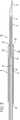
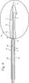
図1は、生体検査または切除処置中に胸部腫瘍を固定するための付着プローブを示す。このプローブは、ジュール−トムソン冷却または液体窒素を使用して先端チップに軽く冷却された領域を生成する。この軽く冷却された領域は疑いのある障害部または腫瘍に付着する。付着プローブ1は、長くて細いが剛性のある剛性チューブ2からなる。短くて剛性のある穿通セグメント3が、剛性チューブの先端から先端側に延びており、適切なハンドル4がチューブの基端に装着されている。ハンドルは迅速解放機構を含み、該迅速解放機構は迅速解放アクチュエータ5により操作可能である。
【0009】
図2は、付着プローブ1の断面であり、剛性チューブ2、先端の穿通セグメント3およびハンドル4を示す。冷却剤入口チューブ10は、ハンドルと剛性チューブを貫通し、剛性チューブの先端に延び、穿通セグメントの先端チップのまさに基端で終わっている。入口チューブは、該入口チューブの先端にオリフィス11を有し、該オリフィスは単にチューブの真直ぐに切断された末端、または入口チューブの隣接上流部より小さな内径を有する小さなノズルであってもよい。剛性チューブは、約(0.065)インチの外径、約(0.047)インチの内径、および約(10)インチの長さを有する基端セグメント12を有する。穿通セグメント3は、第1セグメント13と鋭利な先端チップ14からなる。第1セグメントは、約(0.043)インチの外径、約(0.033)インチの内径、および約(1)インチの長さを有する。断面図から明らかなように、鋭利な先端チップは、中実で、腫瘍を貫いて穿通するのに適している。穿通セグメントの長さは、採取される目標組織の塊とほぼ同じサイズ、または所望のコアサンプルのサイズとなるように選択される。この穿通セグメントは障害部または腫瘍に押し込められる。
【0010】
剛性チューブの基端セグメントと穿通セグメントの第1セグメントの間に、長さが約(.05)インチの剛性チューブのテーパセグメント15がある。ここで、剛性チューブの内外径は、基端セグメントの径から第1セグメントの径までテーパが付いている。環状空間またはルーメン16が、入口チューブの外面と剛性チューブの内面によって、形成されている。入口チューブのオリフィスを出るガスおよび/または液体は環状空間に沿って逆流し、プローブから排出され、該プローブから離れた適当なポイントに達する。アルゴンのようなガスが選ばれた場合、ガスはオリフィスを通って外に導かれるにつれて、ジュール・トムソン膨張を受ける。ガスおよび/または液体が穿通セグメントに導かれてオリフィスを通って出ると、穿通セグメント回りの表面領域が冷却される.約1200−2000psiの圧力で前述したような寸法を有するプローブに供給されたアルゴンガスは、約0℃から−10℃の温度範囲の冷却を与える。3000psiで供給されたガスとともに、付着プローブは約−60℃の低温に到達する。冷却に使用するガスまたは液体は、気体アルゴン、窒素、二酸化炭素、空気、液体窒素、フレオン、フロンガス、フッ化カーボン、その他の適切な冷却剤を含む。ガスはエンドケアクリオケア(登録商標)のような冷凍外科システムを介して提供してもよい。
【0011】
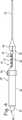
図3は、コア採取カニューレ20と付着プローブ1の間の基本的関係を示す。カニューレは細長いが剛性のあるチューブであり、基端開口21と、先端開口22と、カニューレの基端から先端に延びるルーメン23とを有する。カニューレは、付着プローブの回りにスライド可能に配置され、付着プローブに対して長手方向に移動される。カニューレは皮膚の小さな切口から挿入するように適合され、付着プローブとともに、あるいは付着プローブの上に挿入することができる。次の図面に記載されているように、カニューレは穿通セグメントの上を先端側に押しつけて、穿通セグメントに固定されている組織を周辺身体組織から採取することができる。
【0012】
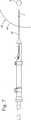
図4は、付着プローブ1およびカニューレ20とともに使用するように適合されたスプリングを装着した生体検査器具24を示す。生体検査器具はハウジング25を有している。ハウジングは、人間の手にあう大きさのグリップ26と、該グリップの先端に容器27を有している。ハウジングの基端では、入口29を備えた接続具28がカニューレのルーメンと連通している。カニューレは入口のハウジング内からハウジングの先端を通って外に延びている。
【0013】
栓体検査器具24はコア採取機構を有する。コア採取機構は、容器27内に収容されたカニューレ平行移動機構を有する。ブロック32が、ハウジング25に取付られまたはハウジングに一体に形成されたレール33にスライド可能に装着されている。グリップを保持する同じ手で容易にボタンを操作することができるように、ブロックと連結可能なトリガーボタン34がグリップ26の近辺に配置されるのが好ましい。スプリング35はブロックとトリガーボタンの間に挿入されている。スプリングは先端側への付勢力をブロックに作用する。容器の先端にはストッパー36がハウジングに取り付けられ、あるいは一体に形成されている。カニューレ20はブロックを貫通して固定して取り付けられ、スプリングにより前方に先端側へ付勢されている。スプリングの先端側への付勢力はブロック、したがってカニューレを付勢して先端側に平行移動させる。スプリングは5から15lbs/インチ、好ましくは7から11lbs/インチのバネ定数を有していてもよい。
【0014】
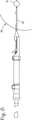
図5と図6は、カニューレ20のルーメン23内の適所にある付着プローブ1を示す。付着プローブはカニューレの基端開口21からルーメンに挿入し、貫通させることができる。プローブを生体検査器具24に固定するために、プローブのハンドル4を接続具28に接続する。ガスおよび/または液体源が供給ラインを介してハンドルに接続される。
【0015】
カニューレ平行移動機構はロック位置37とアンロック位置38をとる。図5はロック位置にある平行移動機構を示す。ロック位置では、スプリング35は圧縮され、ブロック32はトリガーボタン34に連結される。付着プローブの穿通セグメント3が露出され、カニューレ20から先端側に延びる。図6は、カニューレが穿通セグメントの上で先端側に平行移動されて、アンロック位置にある平行移動機構を示す。平行移動機構をロック位置からアンロック位置に移動させるために、トリガーボタンを押圧する。このボタンを押圧すると、ブロックがボタンから外れ、圧縮スプリングからの付勢力がブロックとカニューレを先端側に前方へ付勢する。(任意のラッチ機構を使用して、ブロックを基端位置に解放可能に固定し、ブロックを装置のオペレータが望むように解放してもよい。)ブロックが先端側前方に付勢されると、ブロックとカニューレは、ブロックがストッパ36と係合するまでレール33に沿って平行移動する。カニューレが付着プローブの穿通セグメント上を先端側に平行移動すると、穿通セグメントに付着した任意の組織が周辺の障害部から採取され、装置内で除去される。
【0016】
図7から図10は、使用中の装置を示す。生体検査手順に開始時に、患者を用意し、胸部を適切に準備し布で覆う。部位を局部麻酔およびオプションとして静脈鎮静剤を使用して準備する。患者を寝かせて仰向け状態で手術台に置く。(手順が定位指導(stereotactic guidance)で行なわれる場合、定位台にうつむかせて、台の下方に胸部を露出してもよい。)予め撮像されていない場合は、胸部を撮像し、腫瘍の位置を決定する。約(4)mmの小さな切口を胸部に作り、付着プローブ1とカニューレ20を容易に皮膚に挿入することができるようにする。付着プローブを生体検査器具24に挿入し、これによりカニューレ内に配置し、穿通チップ3をカニューレ20の先端から先端側に延ばす。カニューレ平行移動機構をロック位置37に設定し、穿通セグメントをカニューレの外側に残す。付着プローブの穿通セグメントとカニューレの先端を含む装置の先端を、切口を通して胸部に挿入する。定位指導又は超音波指導の下で、装置の先端を胸部内の目標障害部に誘導する。
【0017】
コア採取手順を図7から図10に示す。図7は、腫瘍を覆う皮膚に作られた切口から挿入される付着プローブ1とカニューレ20を示す。付着プローブがカニューレに挿入され、該付着プローブはカニューレ内に同軸に配置され、その先端穿通セグメントはカニューレの先端から突出する。ハンドルは器具24の基端に固定され、これにより付着プローブと生体検査器具は迅速解放機構を介して互いに係合する。これにより、付着プローブと生体検査器具は単一部品として誘導することができる。患者の胸部39と皮膚40が概略的に示されている。腫瘍障害部または他の疑いのある塊41が胸部内に配置され、柔らかい組織および脂肪の多い組織により囲まれている。超音波スキャナその他の撮像装置を使用して、腫瘍および胸部に挿入された器具を含む胸部の像を得る。外科医は撮像装置からのディスプレイを使用してプローブとカニューレを腫瘍に誘導する。
【0018】
図8は、プローブが腫瘍41を穿通するまで胸部39に挿入された付着プローブ1およびカニューレ20を示す。外科医は、付着プローブの穿通セグメント3が腫瘍を穿通し、剛性チューブ2のテーパセグメント15が腫瘍に近接するまで、プローブとカニューレを胸部に押し込む。
【0019】
図9は、腫瘍41を固定するように活性化された付着プローブ1を示す。生体検査手順中に腫瘍をプローブに固定するために、穿通セグメント3の回りの表面領域を冷却する。ガスまたは液体のいずれかをその供給源から穿通セグメントに導く。外科医がガスを使用する場合、該ガスが冷却剤入口チューブ10のオリフィス11を通って導出されるにつれ、ガスはジュール−トムソン効果により穿通セグメント回りの表面領域を凍結させる。ガス源は高圧縮タンクまたはホイペット(whippet)とすることができる。表面領域は約0℃から−60℃の温度範囲に凍結する。この温度範囲では、冷却された表面領域は腫瘍細胞を除去して腫瘍細胞分析を行なうことを妨げない。この温度範囲に表面領域を冷却するのに、比較的小さな量のガスまたは液体が必要である。オリフィスに存在しおよび管状空間16に沿って逆流するガスまたは液体は、プローブから排出される。冷却された表面領域は該冷却表面領域の回りに接触する腫瘍細胞の薄層を凍結させ、腫瘍はプローブに固定される。身体組織の冷却管状容積は図9に符号42で示されている。
【0020】
図10は、カニューレ平行移動機構を起動して凍結腫瘍41のコアサンプルを切断する状態を示す。一旦腫瘍がプローブ1に固定されると、生体検査器具24を起動して凍結腫瘍のサンプルを採取する。腫瘍の採取を開始するために、トリガーボタン34を介して平行移動機構を操作する(図5参照)。トリガーボタンを押圧すると、カニューレ20が凍結腫瘍に向かって先端側に前進する。カニューレが腫瘍に接触し、鋭利な先端チップに向かって前進するにつれて、カニューレは凍結腫瘍のサンプル43を切り取る。この結果得られたコアサンプルは穿通セグメント3の回りの凍結または部分凍結腫瘍の層である。腫瘍が凍結しているため、通常の生体検査法に比べて、胸部の健康領域への腫瘍細胞の分散およびシーディング(seeding)が最小化される。
【0021】
一旦胸部腫瘍41のサンプルが採取されると、固定したコアサンプルを有する付着プローブ1をカニューレ20に残す。胸部39からコアサンプルを除去するために、生体検査器具24と付着プローブを胸部から後退させ、後退中はコアサンプルをカニューレ内に保護する。生体検査器具およびプローブが胸部の外側に後退すると、コアサンプル43をもつ付着プローブを生体検査器具から引き抜き、図11に示すように、入口29から、またはカニューレの基端開口21から出す。サンプルは付着プローブ1の穿通セグメントに依然として固定されている。サンプルは短時間で溶け、図12に示すような保持トレイに移動することができる。保持トレイ44は壁45を有し、該壁は1または複数のスロット46を有する。スロット高さの少なくとも一部に対して、スロット幅は付着プローブの穿通セグメントの外径と近似する。これにより、付着プローブを溝に滑り落とし、水平方向に引っ張ると、サンプルを穿通セグメントからきれいに外すことができる。付着プローブおよび保持トレイは、外科医によって行なわれる各手順用に販売されているキットに、使い捨てとして設けてもよい。
【0022】
このシステムを使用する他の方法は、生体検査器具24を1回設置する間に複数のサンプリングを行なうことができる。生体検査器具と付着プローブ1の設置、付着プローブの腫瘍41への付着、穿通セグメント3上のカニューレ20の平行移動の後、付着プローブをカニューレの外へ基端側に引っ張る一方、カニューレと生体検査器具を胸部39の適所に残す。そして付着プローブに付着している組織を除去する。カニューレを患者の胸部内の前進位置に残し、付着プローブをカニューレ(同じ空間または生体検査トラック)に再び挿入する。次に、カニューレを引き戻し、腫瘍内(および初期採取空間内)の穿通セグメントを露出する。軽い圧力を胸部の回りに付加し、付着プローブを冷却し、プローブを包囲する追加の円筒形の組織を凍結させる。そして、カニューレを前進させて凍結した組織を採取する。これにより連続した円筒状のコアサンプルが得られる。我々の研究では、この手順は17の連続した円筒コアサンプルを生じた。
【0023】
図13は、図1の付着プローブとともに使用する生体検査ガン50を示す。生体検査ガンは、ハウジング51と、カニューレ20と、該カニューレを先端側に駆動するトリガー52とからなる。ハウジングの基端において、入口54を備えるスナップ連結部53はカニューレのルーメンと連通している。カニューレは入口のハウジング内の入口から、ハウジングの先端を通って外側に延びている。カニューレは皮膚の小さな切口を通って挿入するように適合されている。
【0024】
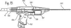
図14および図15は、生体検査ガンの断面図を示す。この断面図に示すように、生体検査ガン50は、コア採取機構を有し、該コア採取機構はカニューレ回転機構とカニューレ平行移動機構を含む。カニューレ回転機構は、モータ57、ピニオンギヤ58および駆動ギヤ59からなる。駆動ギヤはカニューレ20に嵌合する大きさの穴を有している。この穴を通して、カニューレは駆動ギヤに回転可能に固定されている。これにより、駆動ギヤが回転するとカニューレが回転する。ピニオンギヤがモータに一端で回転可能に連結され、そのギヤ歯は駆動ギヤと噛合している。モータが起動すると、該モータによりピニオンギヤが回転する。ピニオンギヤの回転は駆動ギヤに伝達され、駆動ギヤを回転させ、これによりカニューレを回転させる。回転機構はコア採取中に使用され、周辺組織からコアサンプルを切断するのを支援する。
【0025】
カニューレ平行移動機構は、トリガー52と、トリガー上部延長部61と、回動可能アーム62とからなり、アーム62はトリガーに接続された第1端とキャリッジ65に接続された第2端64を有する。キャリッジはトラック66に、該トラックに取り付けられたレール67を介してスライド可能に装着されている。トラックは、ハウジング51に固定して取り付けられ、あるいはハウジングに一体的に形成されて、好ましくはハウジングの両側に二重に設けられている。レールは、アームをキャリッジの基端に回動可能に取り付けることで、トラックにスライド可能に取り付けられている。トリガーは、回動軸ピン68の回りに、ハウジングに回動可能に取り付けられ、アームの第1端に取り付けられている。キャリッジはアームの第2端に取り付けられている。カニューレ20はキャリッジを緩く貫通して取り付けられている。ベアリング69が、キャリッジのいずれかの側で、カニューレに固定されている。これにより、カニューレはキャリッジ内で回転可能であるが、長手方向にキャリッジに対してロックされている。このため、キャリッジの長手方向(基端側または先端側)の移動によりカニューレの長手方向の移動が生じる。
【0026】
カニューレ平行移動機構は、基端位置76と先端位置77をとる。図14は基端位置にある平行移動機構を示し、ここでカニューレは腫瘍に係合していない。基端位置では、キャリッジ65はトラック66の基端に位置し、付着プローブ1の穿通セグメント3は露出して、カニューレから先端側に延びている。図15は先端位置にある平行移動機構を示し、カニューレは付着プローブの穿通セグメント上で先端側に平行移動され、ここで穿通セグメントに固定された腫瘍と係合して腫瘍を採取する。平行移動機構を先端位置に移動するために、トリガー52を押圧する。トリガーを押圧すると、トリガーが回動軸ピン68の回りに回転し、アーム62とレール67をトラックの先端に前進させ、これによりキャリッジをトラックの先端に前進させる。キャリッジがトラックの基端から先端に前進すると、カニューレ20はガン50の基端から先端に前進する。カニューレが前進したときに付着プローブの先端に付着した組織は、周辺障害部から採取され、装置内で除去される。
【0027】
図15はさらに、カニューレ20のルーメン23内の適所にある付着プローブ1を示す。付着プローブをカニューレの基端開口21からルーメンに挿入し、該ルーメンを貫通させる。付着プローブをガン50に固定するために、付着プローブのハンドル4をスナップ結合部53にスナップ嵌合する。ガスおよび/または液体源は供給ラインを介してハンドルに接続する。
【0028】
図16から図19は装置の使用状態を示す。図16は、腫瘍を覆う皮膚に作られた切口を通して挿入されている付着プローブ1とカニューレ20を示す。患者の胸部78及び皮膚79が概略的に示されている。腫瘍、障害、その他疑いのある塊80が胸部内に位置して、柔らかい組織および脂肪のある組織により囲まれている。超音波スキャナまたは他の撮像装置を使用して、腫瘍および胸部に挿入された装置を含む胸部の像を得る。外科医は撮像装置からのディスプレイを使用してプローブおよびカニューレを腫瘍に誘導するのを支援する。
【0029】
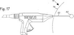
図17は、付着プローブ1とカニューレ20を示し、これらはプローブは腫瘍80に穿通するまで胸部に挿入されている。外科医は、付着プローブ1の穿通セグメント3が腫瘍を穿通し、剛性チューブ2のテーパセグメント15が腫瘍に接近するまで、プローブとカニューレを胸部に押し込む。
【0030】
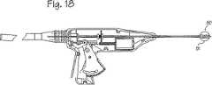
図18は、腫瘍80を固定するために起動されている付着プローブ1を示す。生体検査手順中に腫瘍をプローブに固定するために、穿通セグメント3の回りの表面領域を冷却する。ガスまたは液体のいずれかが供給源から穿通セグメントに導かれる。外科医がガスを使用する場合、該ガスが冷却剤入口チューブ10のオリフィス11を通って導出されるにつれ、ガスはジュール−トムソン効果により穿通セグメント回りの表面領域を凍結させる。冷却された環状体積の身体組織は図18に符号81で示されている。ガス源は高圧縮タンクまたはホイペットとすることができる。表面領域は約0℃から−60℃の温度範囲に凍結する。この温度範囲では、冷却された表面領域は腫瘍細胞を除去して腫瘍細胞分析を行なうことを妨げない。この温度範囲に表面領域を冷却するのに、比較的小さな量のガスまたは液体が必要である。オリフィスに存在しおよび管状空間16に沿って逆流するガスまたは液体は、プローブから排出される。冷却された表面領域は該冷却表面領域の回りに接触する腫瘍細胞の薄層を凍結させ、腫瘍はプローブに固定される。
【0031】
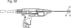
図19は、コア採取機構を起動して凍結腫瘍81のコアサンプルを切断する状態を示す。一旦腫瘍がプローブに固定されると、生体検査ガンを起動して凍結腫瘍のサンプルを採取する。平行移動機構が基端位置にある間に、ガンの回転機構を起動する。腫瘍の採取を開始するために、トリガーを介して平行移動機構を操作する。トリガーボタンを押圧すると、カニューレが凍結腫瘍に向かって先端側に前進する。カニューレが腫瘍に接触し、鋭利な先端チップに向かって前進するにつれて、回転カニューレは凍結腫瘍のサンプルを切り取る。この結果得られコアサンプルは穿通セグメント3の回りの凍結または部分凍結腫瘍の層である。腫瘍が凍結しているため、通常の生体検査法に比べて、胸部の健康領域への腫瘍細胞の分散およびシーディング(seeding)が最小化される。
【0032】
一旦胸部腫瘍のサンプルが採取されると、カニューレを先端位置に残して、コア採取機構を起動する。固定したコアサンプルを有する付着プローブ1をカニューレ20に残す。胸部からコアサンプルを除去するために、生体検査ガンと付着プローブを胸部から後退させ、後退中はコアサンプルをカニューレ内に保護する。ガンおよびプローブが胸部の外側に後退すると、コアサンプル43をもつ付着プローブを生体検査器具から引き抜き、図11に示すように、入口29から、またはカニューレの先端から出す。サンプルは付着プローブ1の穿通セグメントに依然として固定され、前記図12に示すように、除去することができる。
【0033】
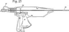
図20は、他のコア採取機構を示し、前図のモータの代わりであるガスタービン83を示す。このタービンは付着プローブからの排気ガスによって駆動され、これにより電気モータの必要性がなくなる。フレキシブルチューブ84が付着チューブの排気径路またはカップリング85を貫通するガス供給ラインに接続され、またタービンに接続されて、排気ガスをタービンに導いている。適切なタービンガス制御弁86を使用してタービンへのガス供給を制御してもよい。カニューレ20は、電気モータに使用された同じタイプのピニオンギヤと駆動ギヤ配置を使用して、ガスタービンに回転可能に連結されている。図21はタービン駆動のコア採取機構の他の例を示し、ここではタービンは、前記実施形態のキャリッジの場所でカニューレに直接装着され、ハウジング内でスライド可能に装着されている。配管87はフレキシブルであり、これにより操作中のタービンの先端および後端への平行移動が許容される。図20と図21のタービン駆動装置は、図4および図13の生体検査器具およびガンと同様に使用することができる。
【0034】
付着プローブおよびその使用方法は、凍結外科システムとともに使用するように発展してきており、その凍結外科システムは、比較的大容量の冷却剤源を制御し、クリオプローブを操作して胸部にある障害部や、腫瘍、その他の目標となる塊を凍結除去するのに使用することができる。付着プローブおよび生体検査装置(生体検査器具および生体検査ガン)は、既存の凍結外科システムと都合よく組み合わせて、手術室に既にある冷却源を利用する。しかし、図22と図23の付着プローブおよび生体検査装置は、スタンドアロン用に設計されているため、外科医は凍結付着方法を利用するために現場で凍結外科システムを必要としない。図22は自給式付着プローブを示す。この自給式付着プローブは穿通セグメント3を備えた剛性チューブ2を含む。剛性チューブの内側には、オリフィス11を備えた冷却剤入口チューブ10が穿通セグメントの第1セグメント13に延びている。剛性チューブの基端には、ねじその他の解放可能な結合部材が設けられ、ガス源への解放可能な取り付けを可能にしている。剛性チューブは鋭利な先端チップ14を備えている。排気ガスは剛性チューブの基端セグメントにあるベント88を介して排気される。ガス源は圧縮ガスの缶(キャニスター)89の形態で設けられている。二酸化炭素(CO2)が適切なガスであり、シリンダ(ホイペットチャージャ、球、またはカプセル)の形で容易に入手できる。液体フレオンその他の冷却剤も適切な冷却剤であり、それらは小さなキャニスターヤスプレー缶で得ることができる。キャニスターはブラケットまたはホルダ90に解放可能に装着される。ホルダは、接続部91を有し、該接続部は剛性ロッドの基端を受け入れ、固定した解放可能なアタッチメントを提供する。ホルダは生体検査装置の基端にある連結部と一致した第2接続部を有する。キャニスターの出口93は、ホルダの貫通口を介して冷却剤入口チューブ10の入口94に導かれている。
【0035】
図23に示すように、剛性チューブはガス源とホルダから取り外されて、単純なニードル形態を提供する。このアセンブリは、ガスホースを使用する実施形態(図7−10および16−19)と全く同じ方法で使用することができるが、「オーバーザワイヤ(over−the−wire)」法で使用してもよい。この方法では、剛性ロッドを操作して患者の胸を穿通し、穿通セグメントを障害部に押し込む。次に、生体検査装置を剛性チューブにねじ込み、剛性チューブの基端を離れ、生体検査装置の基端から僅かに延ばす。そして、冷却剤ホルダを剛性チューブの基端にねじ込み、または固定して、基端の解放可能な接続部をホルダの受入接続部に接続する。次に、前述したように冷却およびコア採取ステップを行なう。この方法により、付着プローブの腫瘍への誘導が容易になり、大きな凍結外科システムへの依存を排除することができる。
【0036】
図24は、図1の付着プローブ1とともに使用するのに適合した気圧操作の生体検査器具100を示す。生体検査器具はハウジング100を有し、該ハウジングは都合のよいハンドルを形成し器具の部品を収容するような大きさと形状である。この器具で使用される種々のチューブは、ハウジングの基端103の入口102を貫通するように取り付けられる。生体検査器具はさらにカニューレ20を有し、該カニューレはハウジング内から該ハウジングの先端104を通って外部に延びている。前記実施形態におけるように、カニューレは付着プローブ上をスライド可能に取り付けられる。付着プローブそれ自身はこの実施形態のハウジングを完全に貫通している。
【0037】
図24に示すように、生体検査器具はコア採取機構を有し、該コア採取機構はカニューレの平行移動機構と回転機構の両方の機能を果たしている。平行移動/コア採取の組合せ機構は、コア採取に要求されるカニューレの長手方向の平行移動を行なう際に、回転操作を行なう。カニューレ平行移動機構は、気圧または液圧アクチュエータ105を有し、該アクチュエータはシリンダまたはピストン室106、基端閉鎖ヘッド107、先端閉鎖ヘッド108、ピストン109、基端閉鎖ヘッドの流体供給口110、リードねじまたはジャッキスクリュからなるねじ形のアクチュエータロッド111からなっている。シリンダはハウジングの内面から形成することができるし、またはシリンダと一体に形成してもよい。ピストンはピストンシリンダ室内の配置されている。これにより、ピストンは、シリンダ室内に嵌合しているが、シリンダに沿って長手方向に往復移動可能である。また、それはシリンダに対して回転可能であってもよい。動作流体はアクチュエータ供給チューブ112を介してアクチュエータに供給される(あるいは引き抜かれる)。供給チューブは(図示しない)動作流体源から、ハウジングの入口102を通って、シリンダ流体供給口に供給される。これにより、チューブの先端はシリンダと連通する。供給チューブと付着プローブは平行関係で入口を貫通している。
【0038】
ピストンは、カニューレ20に取り付けられ、該カニューレに長手方向に固定されている。ピストンはカニューレに回転可能に固定されてもよいが、ピストンに長手方向に固定して、ピストンに対して自由に回転可能にしておいてもよい。ピストンは、カニューレの外径と一致するように選択された径を備えた穴を有している。これにより、カニューレはその穴内でピストンにより緊密に保持される。カニューレはピストンの穴に長手方向に固定されている。これにより、シリンダを貫通する先端側または基端側へのピストンの平行移動はカニューレに伝達される。カニューレはハウジングの基端から、ピストン穴を通り、アクチュエータロッド111を経て、先端閉鎖ヘッドから外部に延びている。(代案として、カニューレは、ピストン室に固定されている限り、シリンダ内の基端側で終わらせることもできる。)図示された実施形態では、付着プローブおよびカニューレは、ピストン、アクチュエータおよびシリンダ内に同軸に配置されている。
【0039】
カニューレ回転機構は、リードねじ111(アクチュエータロッドとしても機能する)とリードねじナット113からなっている。リードねじナットは、先端閉鎖ヘッド内で、ピストンシリンダ106の先端に配置されている(先端閉鎖ヘッドと一体に形成されていてもよい)。リードねじは、外側にねじを備えたチューブと、該チューブを貫通するルーメンとからなっている。リードねじの基端はピストン109に長手方向に固定され、これによりリードねじのルーメンはピストンの穴と連通している。(カニューレはリードねじのルーメンを貫通している。)リードねじナットはリードねじを受け入れるように適合されている。リードねじはリードねじナットにねじ込まれ、これによりリードねじは、ピストンシリンダ106内から、リードねじナットを貫通し、シリンダの外部に延びている。カニューレ20は、リードねじのルーメンを貫通し、リードねじに直接または間接的に回転可能に固定されている。ピストンが平行移動すると、リードねじはピストンの操作で平行移動し、該平行移動を介して回転し、リードねじナットを貫通する。リードねじは、1回転当たり(1)インチのピッチを有し、これにより1インチの平行移動毎に、リードねじは1回転する。カニューレがカニューレに回転可能に固定されているため、リードねじの回転はカニューレに伝達される。
【0040】
カニューレ平行移動機構は、後退/基端位置と伸長/先端位置をとる。図24は後退位置の平行移動機構を示し、ここでカニューレ20は腫瘍と係合していない。後退位置では、ピストンはシリンダの基端に位置し、付着プローブ1の穿通セグメントは露出し、カニューレから先端側に延びている。図25は、伸長位置にある平行移動機構を示し、カニューレが付着プローブの穿通セグメント3上で先端側に平行移動している。ここで、カニューレは、穿通セグメントに固定された腫瘍と係合して該腫瘍を採取する。平行移動機構を後退位置から伸長位置に移動するために、ガスをガス/真空チューブ112を介してシリンダに供給する。ピストンとシリンダの配置に依存するが、ガス圧範囲は約60psiから120psiまでであることが好ましい。しかし、他のピストン−シリンダ配置に依存して、他のガス圧範囲も使用することができる。シリンダ内の十分なガス圧が存在するとき、ピストンはシリンダの先端に向かって先端側に平行移動する。ピストンに操作により、リードねじ111とカニューレは先端側に平行移動される。カニューレは付着チューブの穿通セグメント上で先端側に平行移動する。カニューレが平行移動すると、カニューレはリードねじとリードねじナットのアセンブリの作用により回転する。カニューレが平行移動し回転したときに付着プローブの先端に付着した組織は、周辺障害部から採取され、前記図で説明したように、器具内で除去される。平行移動機構を後退位置に戻すために、真空がガス/真空チューブを介してシリンダに提供される。ピストンを基端側に引き寄せるのに必要な真空度は、ピストンとシリンダの配置に依存して変化する。真空力により、ピストンはシリンダの基端に向かって基端側に平行移動する。シリンダの動作により、リードねじとカニューレは基端側に平行移動し、リードねじがリードねじナットを貫通して引き戻されるにつれて、平行移動中に回転する。これらの図に記載された単一の供給アクチュエータは均等な2つの供給アクチュエータと置換することができる。この場合、高圧動作流体をピストンの両側に供給してピストンを先端および基端側に移動する。しかし、図示の配置はシリンダの構成を単純化し、ハウジング内に収納しなければならない部品点数を減少する。
【0041】
図26は、図24と図25の生体検査器具を操作するための気圧システムの概略図である。冷却ガスは、高圧で収容されたアルゴンや窒素のような冷却ガスのタンク120から高圧ガス供給ライン121を通って供給される。外部圧力調整器122は、圧力接続部123を介して図示のバルブのマニホールドに高圧を供給するために、ライン内の圧力を所望の圧力に調整する。マニホールド内の供給ラインは、内部圧力調整器124を備え、付着プローブに高圧(1000−3000psi)を供給するために、ライン内の圧力を所望の圧力に調整する。マニホールド供給バルブ125と付着プローブ供給バルブ126は、高圧ガスの流れを制御するように操作することができる。高圧ガスバルブ126から、高圧ガス供給ライン121の符号121dで示す下流部分は、高圧接続部127を貫通する付着プローブに接続される。気圧シリンダの制御は、タップライン128からガス圧調整器129を通過する低圧ガスで行なわれる。ガス圧調整器129は約60−120psiの範囲のガスを提供するように設定されているが、圧力範囲はシステム構成に依存して変化させてもよい。低圧調整器はガスを第1の3方向バルブ130に供給し、該第1の3方向バルブは低圧ガスを第2の3方向バルブ131またはジェットベンチュリポンプ133(エジェクターポンプまたは誘導ポンプとも称する)の動作流体入口132に選択的に供給する。第2の3方向バルブは、選択的に、アクチュエータ供給ライン134(圧力接続部135を通ってアクチュエータ供給チューブ112に接続されている)を第1の3方向バルブから供給される動作ガスに接続し、またはアクチュエータ供給チューブ112をジェットベンチュリポンプの真空入口136に接続する。アクチュエータに低圧ガスを供給してコア採取カニューレを先端側に押圧するために、オペレータまたはコントロールシステムは、3方向バルブを操作して、低圧ガス供給源をアクチュエータ供給ライン134に接続し、選択的に、第1の3方向バルブを動作させて高圧ガスを第2の3方向バルブに供給し、または第2の3方向バルブを動作させて高圧ガスをアクチュエータ供給ラインに供給する。真空をアクチュエータに供給してコア採取カニューレを基端側に強制的に後退させるために、オペレータまたはコントロールシステムは、第1の3方向バルブを動作させて低圧ガスをジェットベンチュリポンプの動作流体入口に供給し、第2の3方向バルブを動作させてアクチュエータ供給ラインをジェットベンチュリポンプの真空入口に接続する。このシステムの制御は、種々のバルブを直接オペレータが制御することで達成してもよいし、コンピュータシステムで達成してもよい。ジェットベンチュリポンプとしては、Vaccon Co., Incにより提供されているJSM90型真空ポンプがアクチュエータを動作させるのに適切な真空圧を提供することができる。
【0042】
コア採取手段、平行移動手段および回転手段の種々の実施形態を、図4から図6のスプリング駆動平行移動手段、図13から図15および図24と図25の平行移動および回転手段の代わりに使用することができる。カニューレはスライドボルトを備えることができる。例えば、スライドボルトは手動でホルダに先端側へ押し込んで、カニューレを前進させることができる。カニューレは、コア採取機構の支援なしに、付着プローブの上を単に手動で押し込むことができる。付着プローブは、冷却剤を使用してプローブと目標組織を冷却してプローブを目標組織に付着させる実施形態で説明した。代案として、RF加熱要素、抵抗加熱要素、超音波加熱要素等のような加熱要素を使用して、プローブと目標組織を加熱し、プローブを目標組織に付着させてもよい。このような実施形態では、加熱は、目標組織に深く浸透しない目標組織の軽い壊死に必要な加熱に制限されるべきであり、また組織の小さな長手方向断片に制限されるべきである。これにより、生存能力のある生体検査コアを得ることができる。しかしながら、付着プローブの支援をもって腫瘍や障害部の全体が除去される場合には、加熱は制限する必要はない。
【0043】
前述した装置と方法は、胸部内の腫瘍と障害部の治療に関する。しかし、固定と捜すのが困難な腫瘍がどこにあっても、身体中の腫瘍と障害部を治療するのにも使用することができる。したがって、この装置と方法は、子宮管(子宮筋腫のような)、腎臓、肝臓、前立腺、または脳にも使用することができる。
【0044】
以上のように、本発明の装置と方法の好ましい実施形態をそれが開発された状況を参照して説明したが、それらは本発明の原理を説明するだけのものである。本発明の精神や特許請求の範囲から逸脱することなく、他の実施形態や配置を案出してもよい。
【図面の簡単な説明】
【図1】 生体検査または切除処置中に胸部腫瘍を固定するための付着プローブを示す。
【図2】 図1の付着プローブの断面図である。
【図3】 コア採取カニューレ内の付着プローブを示す。
【図4】 図1及び図2の付着プローブとともに使用するのに適した生体検査器具を示す。
【図5】 図1及び図2の付着プローブとともに使用するのに適した生体検査器具を示す。
【図6】 図1及び図2の付着プローブとともに使用するのに適した生体検査器具を示す。
【図7】 図5及び図6の装置を使用して胸部腫瘍の生体検査を行なう方法を示す。
【図8】 図5及び図6の装置を使用して胸部腫瘍の生体検査を行なう方法を示す。
【図9】 図5及び図6の装置を使用して胸部腫瘍の生体検査を行なう方法を示す。
【図10】 図5及び図6の装置を使用して胸部腫瘍の生体検査を行なう方法を示す。
【図11】 生体検査器具から引き抜かれた付着プローブを示す。
【図12】 付着プローブを保持する保持トレイを示す。
【図13】 図1の付着プローブとともに使用するのに適した生体検査ガンを示す。
【図14】 図13の生体検査ガンの断面図である。
【図15】 図13の生体検査ガンの断面図である。
【図16】 図13の装置を使用して胸部腫瘍の栓体検査を行なう方法を示す。
【図17】 図13の装置を使用して胸部腫瘍の栓体検査を行なう方法を示す。
【図18】 図13の装置を使用して胸部腫瘍の栓体検査を行なう方法を示す。
【図19】 図13の装置を使用して胸部腫瘍の栓体検査を行なう方法を示す。
【図20】 ガスタービンモータを備え、図1の付着プローブとともに使用するのに適した生体検査ガンの断面図である。
【図21】 ガスタービンモータを備え、図1の付着プローブとともに使用するのに適した生体検査ガンの断面図である。
【図22】 小さなボトルに供給された冷却剤を使用する付着プローブの実施形態を示す。
【図23】 小さなボトルに供給された冷却剤を使用する付着プローブの実施形態を示す。
【図24】 図1の付着部ローブを生体検査器具内の適所に備えた気圧操作生体検査器具の断面図である。
【図25】 図1の付着部ローブを生体検査器具内の適所に備えた気圧操作生体検査器具の断面図である。
【図26】 図24および図25の生体検査器具を操作する気圧システムの概略図である。
【符号の説明】
1 付着プローブ
2 剛性チューブ
20 カニューレ[0001]
TECHNICAL FIELD OF THE INVENTION
The devices and methods described below relate to the diagnosis and treatment of chest disorders, and more generally to the diagnosis and treatment of tumors and disorders in the body.
[0002]
Background of the Invention
Biopsy is an important procedure used to diagnose patients with cancer tumors, pre-malignant conditions, and other diseases and disorders. Typically, in the case of cancer, a biopsy is performed when a physician establishes that a suspicious situation exists by procedures such as palpation, mammography, x-ray, or ultrasound imaging. This biopsy helps determine whether the cell is cancer, the type of cancer, and what treatment should be used to treat the cancer. The biopsy may be performed by open surgery or percutaneous surgery. Incisional biopsy is an invasive surgical procedure that uses a scalpel to visually observe a target area, but removes all of the mass (extracted biopsy) or removes part of the mass (incision biopsy). To do. In contrast, percutaneous biopsy is usually performed using a needle-like instrument through a relatively small incision and is usually performed blindly or with the aid of an imaging device, such as needle aspiration cytology (FNA) or core biopsy. Any of inspection may be sufficient. For FNA biopsy, individual cells or populations of cells may be obtained and cytologically examined and prepared as in Papanicolaou smears. In core biopsy, as the term suggests, tissue cores or debris are obtained and histological examination is performed. The histological examination may be performed through a frozen part or a paraffin part. One important area where biopsy is performed is the diagnosis of breast tumors.
[0003]
Traditionally, biopsy techniques for breast tumors involve placing biopsy devices on the chest several times and taking several samples of tissue from a mass or tumor suspected of being cancerous. Some samples are necessary to ensure that some tissue from the suspected mass has been captured, and if there are dispersed cancer cells in the suspected mass, these cancer cells are captured in the sample Collect sufficient organization to ensure that Each time the device is installed, the physician must use ultrasound imaging to install and guide the device to the correct location near the suspected mass. Some breast tumors and injuries are very well defined hard spherical masses that grow in soft and flexible breast tissue. It is difficult to push the needle into these injuries. They are resistant to stinging and moving. Pushing the biopsy needle into the obstruction is like trying to poke a floating float in the water.
[0004]
The vacuum assisted biopsy system proposed by Biopsy requires aspiration of a chest lesion into a cannula and cutting the captured edge of the lesion to obtain a biopsy sample. This device uses a vacuum to collect tissue on the side of the open tubular device and uses a rotating core extractor to cut the collected tissue. The rotating core collector can slide within the tubular section and can be pulled back to remove tissue collected in the rotating core collector. An additional probe can be used within the rotating core collector to push the tissue out of the rotating core collector. The device can be rotated 360 ° around its central part on its axis to remove the sample. Typically, the physician collects 6 to 8 cores. One advantage of this device is that the physician does not need to remove the device for additional biopsy samples. However, the tumor itself must be re-implanted after every core collection operation. This requires substantial effort in repositioning and confirming that the suspicious mass of the target has been embedded in the lateral hole. The tumor is so strong that it does not yield to the aspirator and does not deform as needed to enter the side hole of the cannula. Also, doctors currently use the device to rotate the device about its longitudinal axis to keep the core continuous in a circle, or move the suction head laterally to align the core in a straight line.
[0005]
After biopsy and analysis, the tumor must be treated with a separate device. Biopsy teaches that the coring device should not be used for ablation. In fact, the device is not designed to perform excision with confidence that complete excision of the suspected mass has been achieved. As a result of mechanical cutting or rupture of tissue structure and cancer cell dispersion (ie, tearing of tissue around cancer, movement of cancer cells between normal tissues), cancer cells are unintentionally in healthy tissue near the lesion Delivered.
[0006]
Summary of the Invention
The devices and methods described below are provided for the diagnosis of tumors in the breast. The device includes a probe with a structure that allows a surgeon to fix a suspected mass or tumor in the chest during a biopsy. The probe includes a rigid tube and a sharp tip. To secure the tumor to the probe, the surgeon punctures the tumor with a tip rod. A gas line extending within the rigid tube guides the coolant to the tip and cools the tip, thereby attaching the tumor to the cooled probe.
[0007]
The apparatus further includes a coring apparatus with a structure that allows the surgeon to sample a tumor during a biopsy procedure. The core collection device includes a cannula that advances through the tumor and collects a sample of the tumor. The coring device is suitable for use with a probe. The probe is inserted into the cannula and the tip of the probe extends beyond the tip of the cannula. The surgeon can insert the device into the body until the probe punctures the tumor. Lead the coolant to the tip of the probe and lightly cool the tip and tumor. The lightly cooled tip is attached to the tumor cells. Once secured to the probe, the surgeon can take a sample of the tumor using a core collection device. When core collection is complete, the surgeon retracts the device with the core sample. This biopsy method prevents tumor cell destruction and reduces the dispersion of tumor cells into healthy cell regions.
[0008]
DESCRIPTION OF THE PREFERRED EMBODIMENT
FIG. 1 shows an attachment probe for fixing a breast tumor during a biopsy or ablation procedure. This probe produces a lightly cooled area on the tip using Joule-Thomson cooling or liquid nitrogen. This lightly cooled area adheres to a suspected lesion or tumor. The
[0009]
FIG. 2 is a cross section of the
[0010]
A taper segment of rigid tube approximately (.05) inches in length between the proximal segment of the rigid tube and the first segment of the
[0011]
FIG. 3 shows the basic relationship between the coring
[0012]
FIG. 4 shows a
[0013]
The
[0014]
5 and 6 show the
[0015]
The cannula translation mechanism is in the locked position37 And unlock
[0016]
7 to 10 show the device in use. At the beginning of the biopsy procedure, a patient is prepared and the chest is properly prepared and covered with a cloth. The site is prepared using local anesthesia and optionally venous sedation. Lay the patient on his operating table in a supine position. (If the procedure is performed with stereotactic guidance, you may lie down on a stereotaxic table and expose the chest below the platform.) If not previously imaged, image the chest and position the tumor To decide. A small incision of about (4) mm is made in the chest so that the
[0017]
The core collection procedure is shown in FIGS. FIG. 7 shows the
[0018]
FIG. 8 shows the attached
[0019]
FIG. 9 shows the
[0020]
FIG. 10 shows a state in which the core sample of the
[0021]
Once a sample of
[0022]
Other methods of using this system can perform multiple samplings during a single installation of the
[0023]
FIG. 13 shows a
[0024]
14 and 15 show cross-sectional views of the biopsy gun. As shown in this cross-sectional view, the
[0025]
The cannula translation mechanism includes a
[0026]
The cannula translation mechanism has a proximal position 76 and a distal position 77. FIG. 14 shows the translation mechanism in the proximal position, where the cannula is not engaged with the tumor. In the proximal position, the
[0027]
FIG. 15 further shows the
[0028]
16 to 19 show the usage state of the apparatus. FIG. 16 shows the
[0029]
FIG. 17 shows the
[0030]
FIG. 18 shows the
[0031]
FIG. 19 shows a state where the core collection mechanism is activated and the core sample of the
[0032]
Once the breast tumor sample is taken, the core collection mechanism is activated leaving the cannula in the tip position. The attached
[0033]
FIG. 20 shows another core collection mechanism, and shows a gas turbine 83 that is a substitute for the motor of the previous figure. The turbine is driven by exhaust gas from the attached probe, thereby eliminating the need for an electric motor. A flexible tube 84 is connected to the gas supply line that penetrates the exhaust tube exhaust path or
[0034]
Adhesion probes and methods of use have evolved for use with cryosurgical systems, which control a relatively large volume of coolant source and operate a cryoprobe to provide an obstacle in the chest. Or it can be used to freeze remove tumors and other targeted masses. Adhesion probes and biopsy devices (biopsy instruments and biopsy guns) utilize a cooling source that is already in the operating room, conveniently combined with existing cryosurgical systems. However, because the attachment probe and biopsy device of FIGS. 22 and 23 are designed for stand-alone use, the surgeon does not require a cryosurgical system in the field to utilize the freeze attachment method. FIG. 22 shows a self-contained attachment probe. This self-contained attachment probe includes a
[0035]
As shown in FIG. 23, the rigid tube is removed from the gas source and holder to provide a simple needle configuration. This assembly can be used in exactly the same manner as embodiments using gas hoses (FIGS. 7-10 and 16-19), but may be used in an “over-the-wire” manner. . In this method, the rigid rod is manipulated to penetrate the patient's chest and push the penetration segment into the obstruction. Next, the biopsy device is screwed into the rigid tube, leaving the proximal end of the rigid tube and slightly extending from the proximal end of the biopsy device. Then, the coolant holder is screwed or fixed to the proximal end of the rigid tube, and the releasable connecting portion of the proximal end is connected to the receiving connecting portion of the holder. Next, the cooling and core collection steps are performed as described above. This method facilitates the guidance of the attached probe into the tumor and eliminates reliance on large cryosurgical systems.
[0036]
FIG. 24 shows a pneumatically operated
[0037]
As shown in FIG. 24, the biopsy instrument has a core collection mechanism, and the core collection mechanism functions as both a cannula translation mechanism and a rotation mechanism. The combined translation / core collection mechanism performs a rotation operation when performing the longitudinal translation of the cannula required for core collection. The cannula translation mechanism includes a pneumatic or hydraulic actuator 105, which includes a cylinder or
[0038]
The piston is attached to the
[0039]
The cannula rotating mechanism includes a lead screw 111 (which also functions as an actuator rod) and a lead screw nut 113. The lead screw nut is disposed at the tip of the
[0040]
The cannula translation mechanism assumes a retracted / proximal position and an extended / distal position. FIG. 24 shows the retracted translation mechanism where the
[0041]
26 is a schematic diagram of a barometric system for operating the biopsy instruments of FIGS. 24 and 25. FIG. The cooling gas is supplied through a high pressure
[0042]
Various embodiments of the coring means, translation means and rotation means may be used in place of the spring-driven translation means of FIGS. 4-6 and the translation and rotation means of FIGS. 13-15, 24 and 25. can do. The cannula can comprise a slide bolt. For example, the slide bolt can be manually pushed distally into the holder to advance the cannula. The cannula can simply be pushed manually over the attachment probe without the assistance of the core collection mechanism. The attachment probe has been described in an embodiment where a coolant is used to cool the probe and target tissue to attach the probe to the target tissue. Alternatively, heating elements such as RF heating elements, resistance heating elements, ultrasonic heating elements, etc. may be used to heat the probe and target tissue and attach the probe to the target tissue. In such embodiments, heating should be limited to the heating required for light necrosis of the target tissue that does not penetrate deeply into the target tissue, and should be limited to small longitudinal pieces of tissue. Thereby, a viable biopsy core can be obtained. However, if the entire tumor or lesion is removed with the aid of an attached probe, heating need not be limited.
[0043]
The devices and methods described above relate to the treatment of tumors and lesions in the chest. However, it can also be used to treat tumors and lesions throughout the body wherever there are tumors that are difficult to find and fix. Thus, the device and method can also be used for uterine tracts (such as uterine fibroids), kidneys, liver, prostate, or brain.
[0044]
Thus, while preferred embodiments of the apparatus and method of the present invention have been described with reference to the context in which they were developed, they are merely illustrative of the principles of the present invention. Other embodiments and arrangements may be devised without departing from the spirit of the invention and the scope of the claims.
[Brief description of the drawings]
FIG. 1 shows an attachment probe for fixing a breast tumor during a biopsy or resection procedure.
FIG. 2 is a cross-sectional view of the adhesion probe of FIG.
FIG. 3 shows an attachment probe in a coring cannula.
FIG. 4 illustrates a biopsy instrument suitable for use with the attachment probe of FIGS. 1 and 2;
5 shows a biopsy instrument suitable for use with the attachment probe of FIGS. 1 and 2. FIG.
6 shows a biopsy instrument suitable for use with the attachment probe of FIGS. 1 and 2. FIG.
7 illustrates a method for performing a biopsy of a breast tumor using the apparatus of FIGS. 5 and 6. FIG.
FIG. 8 shows a method for performing a biopsy of a breast tumor using the apparatus of FIGS.
9 illustrates a method for performing a biopsy of a breast tumor using the apparatus of FIGS. 5 and 6. FIG.
10 shows a method for performing a biopsy of a breast tumor using the apparatus of FIGS. 5 and 6. FIG.
FIG. 11 shows the attached probe withdrawn from the biopsy instrument.
FIG. 12 shows a holding tray for holding the attached probe.
13 shows a biopsy gun suitable for use with the attachment probe of FIG.
14 is a cross-sectional view of the biopsy gun of FIG.
15 is a cross-sectional view of the biopsy gun of FIG.
FIG. 16 shows a method for performing a plug examination of a breast tumor using the apparatus of FIG.
FIG. 17 shows a method for performing a plug examination of a breast tumor using the apparatus of FIG.
FIG. 18 shows a method for performing a plug examination of a breast tumor using the apparatus of FIG.
FIG. 19 illustrates a method for performing a plug examination of a breast tumor using the apparatus of FIG.
20 is a cross-sectional view of a biopsy gun with a gas turbine motor and suitable for use with the attachment probe of FIG.
21 is a cross-sectional view of a biopsy gun with a gas turbine motor and suitable for use with the attachment probe of FIG.
FIG. 22 illustrates an embodiment of an attachment probe that uses a coolant supplied to a small bottle.
FIG. 23 shows an embodiment of an attachment probe that uses a coolant supplied to a small bottle.
24 is a cross-sectional view of a pneumatically operated biopsy instrument having the attachment lobe of FIG. 1 in place in the biopsy instrument. FIG.
FIG. 25 is a cross-sectional view of a pneumatically operated biopsy instrument having the attachment lobe of FIG. 1 in place in the biopsy instrument.
26 is a schematic view of a barometric system for operating the biopsy instrument of FIGS. 24 and 25. FIG.
[Explanation of symbols]
1 Attachment probe
2 Rigid tube
20 Cannula
Claims (19)
Translated fromJapanese付着プローブと該付着プローブとともに使用するように適合されたカニューレとからなり、
前記付着プローブは、
基端、先端、第1外径を有する基端セグメントおよび第2外径を有し前記基端セグメントから連続して先端側に延びる先端セグメントを有し、前記第1外径が前記第2外径より大きい、患者の身体に挿入するのに適合した剛性チューブを有し、
前記先端セグメントは前記胸部内の塊に付着するように適合され、
前記カニューレは、
基端、先端、前記基端から前記先端に延びるルーメンを有し、前記ルーメンが前記付着プローブの基端セグメントの第1外径とほぼ一致する内径を有し、
前記カニューレは前記付着プローブ上を前記患者の身体に挿入するように適合され、
前記カニューレは前記付着プローブ上をスライド可能である、
ことを特徴とする生体検査装置。In a biopsy device that fixes and collects the mass during the biopsy of the mass in the chest of a human patient,
An attachment probe and a cannula adapted for use with the attachment probe;
The adhesion probe is
A proximal end, a distal end, a proximal segment having a first outer diameter, and a distal end segment having a second outer diameter andcontinuously extending from the proximal end segment toward the distal end side , wherein the first outer diameter is the second outer diameter; Having a rigid tube that is larger than the diameter and adapted to be inserted into the patient's body;
The tip segment is adapted to adhere to a mass within the chest;
The cannula is
A proximal end, a distal end, and a lumen extending from the proximal end to the distal end, the lumen having an inner diameter that substantially matches a first outer diameter of the proximal segment of the attachment probe;
The cannula is adapted to be inserted into the patient's body over the attachment probe;
The cannula is slidable on the attachment probe;
A biopsy device characterized by that.
付着プローブと該付着プローブとともに使用するのに適合されたコア採取装置とからなり、
前記付着プローブは、
基端、先端、基端セグメントおよび前記基端セグメントから連続して先端側に延びる先端セグメントを有し、前記基端セグメントが前記先端セグメントより大きな外径を有する、患者の身体に挿入するのに適合した剛性チューブを有し、
前記先端セグメントは、前記塊を穿通するのに適合した鋭利な先端チップを有し、
前記剛性チューブ内に配置され、前記剛性チューブの先端に延びて該剛性チューブの先端のオリフィスで終り、前記剛性チューブの内面と前記ガス供給チューブの外面の間に前記プローブからの冷却剤を排出するための環状ルーメンを形成し、前記剛性チューブの先端に冷却剤を供給する高圧ガス供給チューブを有し、
前記コア採取装置は、
貫通して延びて基端開口と先端開口を形成するルーメンを有する、前記患者の身体に挿入するように適合されたカニューレと、
前記カニューレに動作可能に接続されたカニューレ回転機構と、
前記カニューレに動作可能に接続されたカニューレ平行移動機構と、
前記カニューレ、前記回転機構および前記平行移動機構を覆い、基端と先端を有し、前記カニューレが内部から延びて貫通し先端で外に出るようにしたハウジングと、
前記ハウジングの基端に配置され、前記カニューレのルーメンと連通する入口を有し、前記付着プローブを前記コア採取装置に固定するスナップ連結部と、からなり、
前記付着プローブは前記カニューレの基端開口から前記ルーメンを貫通して固定されている、
ことを特徴とする生体検査装置。In a biopsy device that fixes and collects the mass during the biopsy of the mass in the chest of a human patient,
An attachment probe and a coring device adapted for use with the attachment probe;
The adhesion probe is
A proximal end, a distal end, a proximal segment, and a distal segmentextending continuously distally from the proximal segment, the proximal segment having a larger outer diameter than the distal segment for insertion into a patient's body With a suitable rigid tube,
The tip segment has a sharp tip adapted to penetrate the mass;
Disposed inside the rigid tube, extends to the distal end of the rigid tube, ends at the orifice at the distal end of the rigid tube, and discharges coolant from the probe between the inner surface of the rigid tube and the outer surface of the gas supply tube A high-pressure gas supply tube that forms an annular lumen for supplying a coolant to the tip of the rigid tube;
The core collecting device is:
A cannula adapted to be inserted into the patient's body having a lumen extending therethrough to form a proximal opening and a distal opening;
A cannula rotation mechanism operably connected to the cannula;
A cannula translation mechanism operatively connected to the cannula;
A housing that covers the cannula, the rotation mechanism and the translation mechanism and has a proximal end and a distal end, the cannula extending from the inside and penetrating out at the distal end;
A snap connection disposed at a proximal end of the housing and having an inlet in communication with a lumen of the cannula and securing the attachment probe to the coring device;
The attachment probe is fixed through the lumen from the proximal opening of the cannula,
A biopsy device characterized by that.
身体組織に挿入し該身体組織に付着するように適合された付着プローブ;
前記付着プローブは、
基端、先端、基端セグメントおよび前記基端セグメントから連続して先端側に延びる先端セグメントを有し、前記基端セグメントが前記先端セグメントより大きな外径を有する、患者の身体に挿入するのに適合した剛性チューブを有し、
前記先端セグメントは、前記塊を穿通するのに適合した鋭利な先端チップを有し;
前記付着プローブとともに使用するように適合され、先端と基端を有するコア採取機構;
前記コア採取機構は、先端と基端を有し、
貫通して延びて基端開口と先端開口を形成するルーメンを有する、前記患者の身体に挿入するように適合されたカニューレと、
前記カニューレに動作可能に接続されたカニューレ平行移動機構と、
前記カニューレに動作可能に接続されたカニューレ回転機構とからなり;
前記カニューレ、平行移動機構および前記カニューレ回転機構を覆い、基端と先端を有し、前記カニューレが内部から延びて貫通し先端で外に出るようにしたハウジング;
からなり、
前記付着プローブは前記カニューレのルーメンを貫通して嵌合され、
前記カニューレ平行移動機構は、
シリンダ室を有し、基端と先端を有する気圧または液圧シリンダと、
該シリンダのシリンダ室に配置され、該シリンダのシリンダ室に沿って長手方向平行移動が可能で、前記カニューレの外径に近似するようなサイズの穴を有するピストンと、
動作流体源または真空源から延びて前記シリンダのシリンダ室で終わる、前記シリンダのシリンダ室に動作流体を供給しまたは真空を付与するチューブとからなり、
前記カニューレは、前記ピストンの穴を貫通して該ピストンに固定して取り付けられ、前記シリンダの先端を貫通して延び、前記ピストンの動作に応じて先端側または基端側に移動する、
ことを特徴とする生体検査器具。In a biopsy instrument that fixes and collects the mass during the biopsy of the mass in the chest of a human patient,
An attachment probe adapted to be inserted into and attached to body tissue;
The adhesion probe is
A proximal end, a distal end, a proximal segment, and a distal segment extending continuously distally from the proximal segment, the proximal segment having a larger outer diameter than the distal segment for insertion into a patient's body With a suitable rigid tube,
The tip segment has a sharp tip adapted to penetrate the mass;
A coring mechanism adapted for use with the attachment probe and having a distal end and a proximal end;
The core collection mechanism has a distal end and a proximal end;
A cannula adapted to be inserted into the patient's body having a lumen extending therethrough to form a proximal opening and a distal opening;
A cannula translation mechanism operatively connected to the cannula;
A cannula rotation mechanism operably connected to the cannula;
A housing that covers the cannula, the translation mechanism and the cannula rotation mechanism and has a proximal end and a distal end, the cannula extending from the inside and penetrating out at the distal end;
Consists of
The attachment probe is fitted through the lumen of the cannula;
The cannula translation mechanism includes:
A pneumatic or hydraulic cylinder having a cylinder chamber and having a proximal end and a distal end;
A piston disposed in the cylinder chamber of the cylinder, capable of longitudinal translation along the cylinder chamber of the cylinder, and having a hole sized to approximate the outer diameter of the cannula;
A tube extending from a working fluid source or a vacuum source and ending in a cylinder chamber of the cylinder, supplying a working fluid to the cylinder chamber of the cylinder or applying a vacuum;
The cannula is fixedly attached to the piston through the hole of the piston, extends through the distal end of the cylinder, and moves to the distal end side or the proximal end side according to the operation of the piston.
A biopsy device characterized by that.
前記シリンダ内に配置され、第1端と第2端を有し、貫通して延びて前記第1端と第2端に開口を形成するルーメンを有し、該ルーメンが前記カニューレを受け入れるような大きさであり、前記ルーメンが前記ピストンの穴と連通して前記第1端が前記ピストンに取り付けられ、前記シリンダのシリンダ室に沿って長手方向に平行移動可能である、リードねじと、
前記シリンダの先端に配置され、前記リードねじに動作可能に接続されたリードねじナットとからなり、
ここで、前記カニューレは前記リードねじのルーメンを占有し、
前記シリンダのシリンダ室に沿った前記ピストンの長手方向の平行移動は前記リードねじに伝達され、
前記リードねじが長手方向に平行移動すると、前記リードねじが前記リードねじナットの動作により回転し、該リードねじの回転が前記カニューレに伝達され、該カニューレを回転させる請求項7に記載の生体検査器具。The cannula rotating mechanism includes:
A lumen disposed within the cylinder, having a first end and a second end, extending therethrough and forming an opening at the first end and the second end, the lumen receiving the cannula; A lead screw, wherein the lumen is in communication with a hole in the piston, the first end is attached to the piston, and is translatable in a longitudinal direction along a cylinder chamber of the cylinder;
A lead screw nut disposed at the tip of the cylinder and operatively connected to the lead screw;
Wherein the cannula occupies the lead screw lumen;
The longitudinal translation of the piston along the cylinder chamber of the cylinder is transmitted to the lead screw;
The biopsy according to claim 7, wherein when the lead screw is translated in the longitudinal direction, the lead screw is rotated by the operation of the lead screw nut, and the rotation of the lead screw is transmitted to the cannula to rotate the cannula. Instruments.
身体内の組織に付着するように動作可能で、身体に挿入するように適合された付着プローブ;
前記付着プローブは、
基端、先端、基端セグメントおよび前記基端セグメントから連続して先端側に延びる先端セグメントを有し、前記基端セグメントが前記先端セグメントより大きな外径を有する、患者の身体に挿入するのに適合した剛性チューブを有し、
前記先端セグメントは、前記塊を穿通するのに適合した鋭利な先端チップを有し;
前記付着プローブの回りに同軸に配置され、前記付着プローブ上でスライド可能でかつ回転可能であるカニューレ;
シリンダ、該シリンダ内に同軸に配置されたピストン、アクチュエータロッドからなり、前記シリンダへの真空の付与に応じて前記ピストンが前記シリンダ内で長手方向に移動可能で、前記アクチュエータロッドが前記ピストンに長手方向に固定され、前記ピストンおよび前記アクチュエータロッドが前記カニューレに長手方向に固定されている、気圧または液圧アクチュエータ;
からなり、
前記アクチュエータは、前記カニューレが前記付着プローブ上で長手方向にスライドするように動作可能であり、
前記アクチュエータは、前記カニューレが前記付着プローブ上で回転するように動作可能である、
身体から組織サンプルを得る装置。In a device for obtaining a tissue sample from the body,
An attachment probe operable to attach to tissue within the body and adapted to be inserted into the body;
The adhesion probe is
A proximal end, a distal end, a proximal segment, and a distal segment extending continuously distally from the proximal segment, the proximal segment having a larger outer diameter than the distal segment for insertion into a patient's body With a suitable rigid tube,
The tip segment has a sharp tip adapted to penetrate the mass;
The adhesion probe around coaxially disposed of, the possible and possible rotation slide on adhesion probecannula;
A cylinder, a piston coaxially disposed in the cylinder, and an actuator rod, wherein the piston is movable in the longitudinal direction in the cylinder in response to application of a vacuum to the cylinder, and the actuator rod extends longitudinally to the piston. A pneumatic or hydraulic actuator fixed in a direction, wherein the piston and the actuator rod are fixed longitudinally to the cannula;
Consists of
The actuator is operable to cause the cannula to slide longitudinally over the attachment probe;
The actuator is operable to rotate the cannula over the attachment probe;
A device that obtains a tissue sample from the body.
身体組織に挿入し該身体組織に付着するように適合された付着プローブ;
前記付着プローブは、
基端、先端、基端セグメントおよび前記基端セグメントから連続して先端側に延びる先端セグメントを有し、前記基端セグメントが前記先端セグメントより大きな外径を有する、患者の身体に挿入するのに適合した剛性チューブを有し、
前記先端セグメントは、前記塊を穿通するのに適合した鋭利な先端チップを有し;
前記付着プローブとともに使用するように適合され、先端と基端を有するコア採取機構;
前記コア採取機構は、
貫通して延びて基端開口と先端開口を形成するルーメンを有する、前記患者の身体に挿入するように適合されたカニューレと、
前記カニューレに動作可能に接続されたカニューレ平行移動機構と、
前記カニューレに動作可能に接続されたカニューレ回転機構とからなり;
前記カニューレ平行移動機構および前記カニューレ回転機構を覆い、基端と先端を有し、前記カニューレが内部から延びて貫通し先端で外に出るようにしたハウジング;
からなり、
前記付着プローブは前記カニューレのルーメンを貫通して嵌合され、
前記カニューレ平行移動機構は、
シリンダ室を有し、基端と先端を有する気圧または液圧シリンダと、
該シリンダのシリンダ室に配置され、該シリンダのシリンダ室に沿って長手方向平行移動が可能で、前記カニューレの外径に近似するようなサイズの穴を有するピストンとからなり、
前記カニューレは、前記ピストンの穴を貫通して該ピストンに固定して取り付けられ、前記シリンダの先端を貫通して延び、前記ピストンの動作に応じて先端側または基端側に移動する、
ことを特徴とする生体検査器具。In a biopsy instrument that fixes and collects the mass during the biopsy of the mass in the chest of a human patient,
An attachment probe adapted to be inserted into and attached to body tissue;
The adhesion probe is
A proximal end, a distal end, a proximal segment, and a distal segment extending continuously distally from the proximal segment, the proximal segment having a larger outer diameter than the distal segment for insertion into a patient's body With a suitable rigid tube,
The tip segment has a sharp tip adapted to penetrate the mass;
A coring mechanism adapted for use with the attachment probe and having a distal end and a proximal end;
The core collection mechanism is
A cannula adapted to be inserted into the patient's body having a lumen extending therethrough to form a proximal opening and a distal opening;
A cannula translation mechanism operatively connected to the cannula;
A cannula rotation mechanism operably connected to the cannula;
A housing that covers the cannula translation mechanism and the cannula rotation mechanism and has a proximal end and a distal end, the cannula extending from the inside and penetrating out at the distal end;
Consists of
The attachment probe is fitted through the lumen of the cannula;
The cannula translation mechanism includes:
A pneumatic or hydraulic cylinder having a cylinder chamber and having a proximal end and a distal end;
A piston disposed in the cylinder chamber of the cylinder, capable of longitudinal translation along the cylinder chamber of the cylinder, and having a hole of a size approximating the outer diameter of the cannula;
The cannula is fixedly attached to the piston through the hole of the piston, extends through the distal end of the cylinder, and moves to the distal end side or the proximal end side according to the operation of the piston.
A biopsy device characterized by that.
前記シリンダ内に配置され、第1端と第2端を有し、貫通して延びて前記第1端と第2端に開口を形成するルーメンを有し、該ルーメンが前記カニューレを受け入れるような大きさであり、前記ルーメンが前記ピストンの穴と連通して前記第1端が前記ピストンに取り付けられ、前記シリンダのシリンダ室に沿って長手方向に平行移動可能である、リードねじと、
前記シリンダの先端に配置され、前記リードねじに動作可能に接続されたリードねじナットとからなり、
ここで、前記カニューレは前記リードねじのルーメンを占有し、
前記シリンダのシリンダ室に沿った前記ピストンの長手方向の平行移動は前記リードねじに伝達され、
前記リードねじが長手方向に平行移動すると、前記リードねじが前記リードねじナットの動作により回転し、該リードねじの回転が前記カニューレに伝達され、該カニューレを回転させる請求項10に記載の生体検査器具。The cannula rotating mechanism includes:
A lumen disposed within the cylinder, having a first end and a second end, extending therethrough and forming an opening at the first end and the second end, the lumen receiving the cannula; A lead screw, wherein the lumen is in communication with a hole in the piston, the first end is attached to the piston, and is translatable in a longitudinal direction along a cylinder chamber of the cylinder;
A lead screw nut disposed at the tip of the cylinder and operatively connected to the lead screw;
Wherein the cannula occupies the lead screw lumen;
The longitudinal translation of the piston along the cylinder chamber of the cylinder is transmitted to the lead screw;
The biopsy according to claim 10, wherein when the lead screw is translated in the longitudinal direction, the lead screw is rotated by the operation of the lead screw nut, and the rotation of the lead screw is transmitted to the cannula to rotate the cannula. Instruments.
身体組織に挿入し該身体組織に付着するように適合された付着プローブ;
前記付着プローブは、
基端、先端、基端セグメントおよび前記基端セグメントから連続して先端側に延びる先端セグメントを有し、前記基端セグメントが前記先端セグメントより大きな外径を有する、患者の身体に挿入するのに適合した剛性チューブを有し、
前記先端セグメントは、前記塊を穿通するのに適合した鋭利な先端チップを有し;
前記付着プローブとともに使用するように適合され、先端と基端を有するコア採取機構;
前記コア採取機構は、
貫通して延びて基端開口と先端開口を形成するルーメンを有する、前記患者の身体に挿入するように適合されたカニューレと、
前記カニューレに動作可能に接続されたカニューレ平行移動機構と、
前記カニューレに動作可能に接続されたカニューレ回転機構とからなり;
前記カニューレ平行移動機構および前記カニューレ回転機構を覆い、基端と先端を有し、前記カニューレが内部から延びて貫通し先端で外に出るようにしたハウジング;
からなり、
前記付着プローブは前記カニューレのルーメンを貫通して嵌合され、
前記カニューレ平行移動機構は、
シリンダ室を有し、基端と先端を有する気圧または液圧シリンダと、
該シリンダのシリンダ室に配置され、該シリンダのシリンダ室に沿って長手方向平行移動が可能であるピストンとからなり、
前記カニューレは、前記ピストンの穴を貫通して該ピストンに固定して取り付けられ、前記シリンダの先端を貫通して延び、前記ピストンの動作に応じて先端側または基端側に移動する、
ことを特徴とする生体検査器具。In a biopsy instrument that fixes and collects the mass during the biopsy of the mass in the chest of a human patient,
An attachment probe adapted to be inserted into and attached to body tissue;
The adhesion probe is
A proximal end, a distal end, a proximal segment, and a distal segment extending continuously distally from the proximal segment, the proximal segment having a larger outer diameter than the distal segment for insertion into a patient's body With a suitable rigid tube,
The tip segment has a sharp tip adapted to penetrate the mass;
A coring mechanism adapted for use with the attachment probe and having a distal end and a proximal end;
The core collection mechanism is
A cannula adapted to be inserted into the patient's body having a lumen extending therethrough to form a proximal opening and a distal opening;
A cannula translation mechanism operatively connected to the cannula;
A cannula rotation mechanism operably connected to the cannula;
A housing that covers the cannula translation mechanism and the cannula rotation mechanism and has a proximal end and a distal end, the cannula extending from the inside and penetrating out at the distal end;
Consists of
The attachment probe is fitted through the lumen of the cannula;
The cannula translation mechanism includes:
A pneumatic or hydraulic cylinder having a cylinder chamber and having a proximal end and a distal end;
A piston disposed in the cylinder chamber of the cylinder and capable of longitudinal translation along the cylinder chamber of the cylinder;
The cannula is fixedly attached to the piston through the hole of the piston, extends through the distal end of the cylinder, and moves to the distal end side or the proximal end side according to the operation of the piston.
A biopsy device characterized by that.
前記シリンダ内に配置され、第1端と第2端を有し、貫通して延びて前記第1端と第2端に開口を形成するルーメンを有し、該ルーメンが前記カニューレを受け入れるような大きさであり、前記ルーメンが前記ピストンの穴と連通して前記第1端が前記ピストンに取り付けられ、前記シリンダのシリンダ室に沿って長手方向に平行移動可能である、リードねじと、
前記シリンダの先端に配置され、前記リードねじに動作可能に接続されたリードねじナットとからなり、
ここで、前記カニューレは前記リードねじのルーメンを占有し、
前記シリンダのシリンダ室に沿った前記ピストンの長手方向の平行移動は前記リードねじに伝達され、
前記リードねじが長手方向に平行移動すると、前記リードねじが前記リードねじナットの動作により回転し、該リードねじの回転が前記カニューレに伝達され、該カニューレを回転させる請求項12に記載の生体検査器具。The cannula rotating mechanism includes:
A lumen disposed within the cylinder, having a first end and a second end, extending therethrough and forming an opening at the first end and the second end, the lumen receiving the cannula; A lead screw, wherein the lumen is in communication with a hole in the piston, the first end is attached to the piston, and is translatable in a longitudinal direction along a cylinder chamber of the cylinder;
A lead screw nut disposed at the tip of the cylinder and operatively connected to the lead screw;
Wherein the cannula occupies the lead screw lumen;
The longitudinal translation of the piston along the cylinder chamber of the cylinder is transmitted to the lead screw;
The biopsy according to claim 12, wherein when the lead screw is translated in the longitudinal direction, the lead screw is rotated by the operation of the lead screw nut, and the rotation of the lead screw is transmitted to the cannula to rotate the cannula. Instruments.
付着プローブと該付着プローブとともに使用するのに適合されたコア採取機構とからなり、
前記付着プローブは、
基端、先端、基端セグメントおよび前記基端セグメントから連続して先端側に延びる先端セグメントを有し、前記基端セグメントが前記先端セグメントより大きな外径を有する、患者の身体に挿入するのに適合した剛性チューブを有し、
前記先端セグメントは、前記塊を穿通するのに適合した鋭利な先端チップを有し、
前記剛性チューブ内に配置され、前記剛性チューブの先端に延びて該剛性チューブの先端のオリフィスで終り、前記剛性チューブの内面との間に前記プローブからの冷却剤を排出するための環状ルーメンを形成し、前記剛性チューブの先端に冷却剤を供給する高圧ガス供給チューブを有し、
前記コア採取機構は、
貫通して延びて基端開口と先端開口を形成するルーメンを有する、前記患者の身体に挿入するように適合されたカニューレと、
前記カニューレに動作可能に接続されたカニューレ平行移動機構と、
前記カニューレに動作可能に接続されたカニューレ回転機構とからなり、
前記カニューレ、前記カニューレ平行移動機構および前記カニューレ回転機構を覆い、基端と先端を有し、前記カニューレが内部から延びて貫通し先端で外に出るようにしたハウジングとからなり、
前記付着プローブは前記カニューレの基端開口から前記ルーメンを貫通して固定され、
シリンダ室を有し、基端と先端を有するシリンダと、
該シリンダのシリンダ室に配置され、該シリンダのシリンダ室に沿って長手方向平行移動が可能で、前記カニューレの外径に近似するようなサイズの穴を有するピストンとからなり、
前記カニューレは、前記ピストンの穴を貫通して該ピストンに固定して取り付けられ、前記シリンダの先端を貫通して延び、
後退位置では、前記ピストンは前記シリンダの基端に位置し、前記付着プローブの先端セグメントは前記カニューレの先端開口から延び、
伸長位置では、前記ピストンは前記シリンダの先端に位置し、前記カニューレの先端開口は前記付着プローブの先端セグメントの上を延びる、
ことを特徴とする生体検査器具。In a biopsy instrument that fixes and collects the mass during the biopsy of the mass in the chest of a human patient,
Consisting of an attachment probe and a core collection mechanism adapted for use with the attachment probe;
The adhesion probe is
A proximal end, a distal end, a proximal segment, and a distal segmentextending continuously distally from the proximal segment, the proximal segment having a larger outer diameter than the distal segment for insertion into a patient's body With a suitable rigid tube,
The tip segment has a sharp tip adapted to penetrate the mass;
An annular lumen is disposed within the rigid tube, extends to the distal end of the rigid tube, terminates at an orifice at the distal end of the rigid tube,and discharges coolant from the probe between the inner surfaceof the rigid tube. And a high pressure gas supply tube for supplying a coolant to the tip of the rigid tube,
The core collection mechanism is
A cannula adapted to be inserted into the patient's body having a lumen extending therethrough to form a proximal opening and a distal opening;
A cannula translation mechanism operatively connected to the cannula;
A cannula rotation mechanism operatively connected to the cannula,
Comprising a housing covering the cannula, the cannula translation mechanism and the cannula rotation mechanism, having a proximal end and a distal end, the cannula extending from the inside and penetrating out at the distal end;
The attachment probe is secured through the lumen from the proximal opening of the cannula;
A cylinder having a cylinder chamber and having a proximal end and a distal end;
A piston disposed in the cylinder chamber of the cylinder, capable of longitudinal translation along the cylinder chamber of the cylinder, and having a hole of a size approximating the outer diameter of the cannula;
The cannula is fixedly attached to the piston through the hole in the piston and extends through the tip of the cylinder;
In the retracted position, the piston is located at the proximal end of the cylinder, the distal segment of the attachment probe extends from the distal opening of the cannula,
In the extended position, the piston is located at the tip of the cylinder, and the tip opening of the cannula extends over the tip segment of the attachment probe;
A biopsy device characterized by that.
前記シリンダ内に配置され、第1端と第2端を有し、貫通して延びて前記第1端と第2端に開口を形成するルーメンを有し、該ルーメンが前記カニューレを受け入れるような大きさであり、前記ルーメンが前記ピストンの穴と連通して前記第1端が前記ピストンに取り付けられ、前記シリンダのシリンダ室に沿って長手方向に平行移動可能である、リードねじと、
前記シリンダの先端に配置され、前記リードねじに動作可能に接続されたリードねじナットとからなり、
ここで、前記カニューレは前記リードねじのルーメンを貫通して前記リードねじに取り付けられ、
前記シリンダのシリンダ室に沿った前記ピストンの長手方向の平行移動は前記リードねじに伝達され、
前記リードねじが長手方向に平行移動すると、前記リードねじが前記リードねじナットの動作により回転し、該リードねじの回転が前記カニューレに伝達され、該カニューレを回転させる請求項14に記載の生体検査器具。The cannula rotating mechanism includes:
A lumen disposed within the cylinder, having a first end and a second end, extending therethrough and forming an opening at the first end and the second end, the lumen receiving the cannula; A lead screw, wherein the lumen is in communication with a hole in the piston, the first end is attached to the piston, and is translatable in a longitudinal direction along a cylinder chamber of the cylinder;
A lead screw nut disposed at the tip of the cylinder and operatively connected to the lead screw;
Wherein the cannula is attached to the lead screw through the lumen of the lead screw;
The longitudinal translation of the piston along the cylinder chamber of the cylinder is transmitted to the lead screw;
The biopsy according to claim 14, wherein when the lead screw is translated in the longitudinal direction, the lead screw is rotated by the operation of the lead screw nut, and the rotation of the lead screw is transmitted to the cannula to rotate the cannula. Instruments.
付着プローブと該付着プローブとともに使用するのに適合されたコア採取機構とからなり、
前記付着プローブは、
基端、先端、基端セグメントおよび前記基端セグメントから連続して先端側に延びる先端セグメントを有し、前記基端セグメントが前記先端セグメントより大きな外径を有する、患者の身体に挿入するのに適合した剛性チューブを有し、
前記先端セグメントは、前記塊を穿通するのに適合した鋭利な先端チップを有し、
前記剛性チューブ内に配置され、前記剛性チューブの先端に延びて該剛性チューブの先端のオリフィスで終り、前記剛性チューブの内面との間に前記プローブからの冷却剤を排出するための環状ルーメンを形成し、前記剛性チューブの先端に冷却剤を供給する高圧ガス供給チューブを有し、
前記コア採取機構は、
貫通して延びて基端開口と先端開口を形成するルーメンとを有する、前記患者の身体に挿入するように適合されたカニューレと、
前記カニューレに動作可能に接続されたカニューレ平行移動機構と、
前記カニューレに動作可能に接続されたカニューレ回転機構とからなり、
前記カニューレ、前記カニューレ平行移動機構および前記カニューレ回転機構を覆い、基端と先端を有し、前記カニューレが内部から延びて貫通し先端で外に出るようにしたハウジングとからなり、
前記付着プローブは前記カニューレの基端開口から前記ルーメンを貫通して固定され、
前記カニューレ平行移動機構は、
シリンダ室を有し、基端と先端を有するシリンダと、
該シリンダのシリンダ室に配置され、該シリンダのシリンダ室に沿って長手方向平行移動が可能であるピストンとからなり、
前記カニューレは、前記ピストンに固定して取り付けられ、前記シリンダの先端を貫通して延び、
後退位置では、前記ピストンは前記シリンダの基端に位置し、前記付着プローブの先端セグメントは前記カニューレの先端開口から延び、
伸長位置では、前記ピストンは前記シリンダの先端に位置し、前記カニューレの先端開口は前記付着プローブの先端セグメントの上を延びる、
ことを特徴とする生体検査器具。In a biopsy instrument that fixes and collects the mass during the biopsy of the mass in the chest of a human patient,
Consisting of an attachment probe and a core collection mechanism adapted for use with the attachment probe;
The adhesion probe is
A proximal end, a distal end, a proximal segment, and a distal segmentextending continuously distally from the proximal segment, the proximal segment having a larger outer diameter than the distal segment for insertion into a patient's body With a suitable rigid tube,
The tip segment has a sharp tip adapted to penetrate the mass;
An annular lumen is disposed within the rigid tube, extends to the distal end of the rigid tube, terminates at an orifice at the distal end of the rigid tube,and discharges coolant from the probe between the inner surfaceof the rigid tube. And a high pressure gas supply tube for supplying a coolant to the tip of the rigid tube,
The core collection mechanism is
A cannula adapted to be inserted into the patient's body having a lumen extending therethrough to form a proximal opening and a distal opening;
A cannula translation mechanism operatively connected to the cannula;
A cannula rotation mechanism operatively connected to the cannula,
Comprising a housing covering the cannula, the cannula translation mechanism and the cannula rotation mechanism, having a proximal end and a distal end, the cannula extending from the inside and penetrating out at the distal end;
The attachment probe is secured through the lumen from the proximal opening of the cannula;
The cannula translation mechanism includes:
A cylinder having a cylinder chamber and having a proximal end and a distal end;
A piston disposed in the cylinder chamber of the cylinder and capable of longitudinal translation along the cylinder chamber of the cylinder;
The cannula is fixedly attached to the piston and extends through the tip of the cylinder;
In the retracted position, the piston is located at the proximal end of the cylinder, the distal segment of the attachment probe extends from the distal opening of the cannula,
In the extended position, the piston is located at the tip of the cylinder, and the tip opening of the cannula extends over the tip segment of the attachment probe;
A biopsy device characterized by that.
前記シリンダ内に配置され、第1端と第2端を有し、貫通して延びて前記第1端と第2端に開口を形成するルーメンを有し、該ルーメンが前記カニューレを受け入れるような大きさであり、前記ルーメンが前記ピストンの穴と連通して前記第1端が前記ピストンに取り付けられ、前記シリンダのシリンダ室に沿って長手方向に平行移動可能である、リードねじと、
前記シリンダの先端に配置され、前記リードねじに動作可能に接続されたリードねじナットとからなり、
ここで、前記カニューレは前記リードねじのルーメンを貫通して前記リードねじに取り付けられ、
前記シリンダのシリンダ室に沿った前記ピストンの長手方向の平行移動は前記リードねじに伝達され、
前記リードねじが長手方向に平行移動すると、前記リードねじが前記リードねじナットの動作により回転し、該リードねじの回転が前記カニューレに伝達され、該カニューレを回転させる請求項18に記載の生体検査器具。The cannula rotating mechanism includes:
A lumen disposed within the cylinder, having a first end and a second end, extending therethrough and forming an opening at the first end and the second end, the lumen receiving the cannula; A lead screw, wherein the lumen is in communication with a hole in the piston, the first end is attached to the piston, and is translatable in a longitudinal direction along a cylinder chamber of the cylinder;
A lead screw nut disposed at the tip of the cylinder and operatively connected to the lead screw;
Wherein the cannula is attached to the lead screw through the lumen of the lead screw;
The longitudinal translation of the piston along the cylinder chamber of the cylinder is transmitted to the lead screw;
The biopsy according to claim 18, wherein when the lead screw is translated in the longitudinal direction, the lead screw is rotated by the operation of the lead screw nut, and the rotation of the lead screw is transmitted to the cannula to rotate the cannula. Instruments.
Applications Claiming Priority (3)
| Application Number | Priority Date | Filing Date | Title |
|---|---|---|---|
| US09/690,321US6540694B1 (en) | 2000-10-16 | 2000-10-16 | Device for biopsy tumors |
| US09/847,931US6551255B2 (en) | 2000-10-16 | 2001-05-03 | Device for biopsy of tumors |
| PCT/US2001/031579WO2002032318A1 (en) | 2000-10-16 | 2001-10-09 | Device for biopsy of tumors |
Publications (3)
| Publication Number | Publication Date |
|---|---|
| JP2004511292A JP2004511292A (en) | 2004-04-15 |
| JP2004511292A5 JP2004511292A5 (en) | 2005-12-22 |
| JP4108473B2true JP4108473B2 (en) | 2008-06-25 |
Family
ID=27104576
Family Applications (1)
| Application Number | Title | Priority Date | Filing Date |
|---|---|---|---|
| JP2002535557AExpired - Fee RelatedJP4108473B2 (en) | 2000-10-16 | 2001-10-09 | Tumor biopsy device |
Country Status (7)
| Country | Link |
|---|---|
| US (3) | US7311672B2 (en) |
| EP (1) | EP1333759B1 (en) |
| JP (1) | JP4108473B2 (en) |
| AU (2) | AU2002211568B2 (en) |
| BR (1) | BR0114716A (en) |
| CA (1) | CA2425793A1 (en) |
| WO (1) | WO2002032318A1 (en) |
Families Citing this family (126)
| Publication number | Priority date | Publication date | Assignee | Title |
|---|---|---|---|---|
| AU2002211568B2 (en)* | 2000-10-16 | 2005-11-17 | Sanarus Medical, Inc. | Device for biopsy of tumors |
| EP1524940B1 (en) | 2002-03-19 | 2011-08-24 | Bard Dublin ITC Limited | Biopsy device and biopsy needle module that can be inserted into the biopsy device |
| US8109885B2 (en) | 2002-03-19 | 2012-02-07 | C. R. Bard, Inc. | Biopsy device for removing tissue specimens using a vacuum |
| US9314228B2 (en) | 2002-05-31 | 2016-04-19 | Vidacare LLC | Apparatus and method for accessing the bone marrow |
| US9451968B2 (en) | 2002-05-31 | 2016-09-27 | Vidacare LLC | Powered drivers, intraosseous devices and methods to access bone marrow |
| US11337728B2 (en) | 2002-05-31 | 2022-05-24 | Teleflex Life Sciences Limited | Powered drivers, intraosseous devices and methods to access bone marrow |
| US20070049945A1 (en) | 2002-05-31 | 2007-03-01 | Miller Larry J | Apparatus and methods to install, support and/or monitor performance of intraosseous devices |
| US11298202B2 (en) | 2002-05-31 | 2022-04-12 | Teleflex Life Sciences Limited | Biopsy devices and related methods |
| US8668698B2 (en) | 2002-05-31 | 2014-03-11 | Vidacare Corporation | Assembly for coupling powered driver with intraosseous device |
| EP2039298B1 (en) | 2002-05-31 | 2017-10-25 | Vidacare LLC | Apparatus to access bone marrow |
| US7811260B2 (en) | 2002-05-31 | 2010-10-12 | Vidacare Corporation | Apparatus and method to inject fluids into bone marrow and other target sites |
| US8142365B2 (en) | 2002-05-31 | 2012-03-27 | Vidacare Corporation | Apparatus and method for accessing the bone marrow of the sternum |
| US8690791B2 (en) | 2002-05-31 | 2014-04-08 | Vidacare Corporation | Apparatus and method to access the bone marrow |
| US7850620B2 (en) | 2002-05-31 | 2010-12-14 | Vidacare Corporation | Biopsy devices and related methods |
| US9072543B2 (en) | 2002-05-31 | 2015-07-07 | Vidacare LLC | Vascular access kits and methods |
| US10973545B2 (en) | 2002-05-31 | 2021-04-13 | Teleflex Life Sciences Limited | Powered drivers, intraosseous devices and methods to access bone marrow |
| US8641715B2 (en) | 2002-05-31 | 2014-02-04 | Vidacare Corporation | Manual intraosseous device |
| US7951089B2 (en) | 2002-05-31 | 2011-05-31 | Vidacare Corporation | Apparatus and methods to harvest bone and bone marrow |
| US10973532B2 (en) | 2002-05-31 | 2021-04-13 | Teleflex Life Sciences Limited | Powered drivers, intraosseous devices and methods to access bone marrow |
| DE20305093U1 (en) | 2003-03-29 | 2003-09-11 | Heske, Norbert F., 82288 Kottgeisering | Coaxial cannula with sealing element |
| DE10314240B4 (en) | 2003-03-29 | 2025-05-28 | Bard Dublin Itc Ltd. | Pressure generation unit |
| US9504477B2 (en) | 2003-05-30 | 2016-11-29 | Vidacare LLC | Powered driver |
| US7625346B2 (en)* | 2003-05-30 | 2009-12-01 | Boston Scientific Scimed, Inc. | Transbronchial needle aspiration device |
| US11877781B2 (en)* | 2003-06-25 | 2024-01-23 | Varian Medical Systems, Inc. | Cryosurgical probe with adjustable sliding apparatus |
| US8357103B2 (en) | 2003-10-14 | 2013-01-22 | Suros Surgical Systems, Inc. | Vacuum assisted biopsy needle set |
| JP4500315B2 (en) | 2003-10-14 | 2010-07-14 | シュロス・サージカル・システムズ・インコーポレーテッド | Vacuum assisted biopsy needle set |
| US7988642B2 (en) | 2003-10-14 | 2011-08-02 | Suros Surgical Systems, Inc. | Vacuum assisted biopsy device |
| US8048003B2 (en) | 2003-10-14 | 2011-11-01 | Suros Surgical Systems, Inc. | Vacuum assisted biopsy device |
| CN101536926B (en) | 2004-01-26 | 2012-07-18 | 维达保健公司 | Manual interosseous device |
| US7815642B2 (en) | 2004-01-26 | 2010-10-19 | Vidacare Corporation | Impact-driven intraosseous needle |
| US8932233B2 (en) | 2004-05-21 | 2015-01-13 | Devicor Medical Products, Inc. | MRI biopsy device |
| US9638770B2 (en) | 2004-05-21 | 2017-05-02 | Devicor Medical Products, Inc. | MRI biopsy apparatus incorporating an imageable penetrating portion |
| US7708751B2 (en) | 2004-05-21 | 2010-05-04 | Ethicon Endo-Surgery, Inc. | MRI biopsy device |
| JP4814229B2 (en) | 2004-07-09 | 2011-11-16 | バード ペリフェラル ヴァスキュラー インコーポレイテッド | Transport device for biopsy device |
| US8998848B2 (en) | 2004-11-12 | 2015-04-07 | Vidacare LLC | Intraosseous device and methods for accessing bone marrow in the sternum and other target areas |
| US7517321B2 (en) | 2005-01-31 | 2009-04-14 | C. R. Bard, Inc. | Quick cycle biopsy system |
| US7850683B2 (en) | 2005-05-20 | 2010-12-14 | Myoscience, Inc. | Subdermal cryogenic remodeling of muscles, nerves, connective tissue, and/or adipose tissue (fat) |
| US7713266B2 (en) | 2005-05-20 | 2010-05-11 | Myoscience, Inc. | Subdermal cryogenic remodeling of muscles, nerves, connective tissue, and/or adipose tissue (fat) |
| EP1921998B8 (en) | 2005-08-10 | 2021-07-07 | C.R.Bard, Inc. | Single-insertion, multiple sampling biopsy device with linear drive |
| ES2539578T3 (en) | 2005-08-10 | 2015-07-02 | C.R. Bard, Inc. | Multi-sample biopsy device and single insert with various transport systems |
| JP4991723B2 (en) | 2005-08-10 | 2012-08-01 | シー・アール・バード・インコーポレーテッド | Single insertion multiple sampling biopsy device with integrated marker |
| US20070156125A1 (en)* | 2005-12-30 | 2007-07-05 | Russell Delonzor | Encodable cryogenic device |
| US20070191732A1 (en)* | 2006-02-10 | 2007-08-16 | Voegele James W | Cryogenic probe |
| EP3417792B1 (en) | 2006-08-21 | 2022-03-02 | C. R. Bard, Inc. | Self-contained handheld biopsy needle |
| EP2073728B1 (en) | 2006-09-12 | 2018-11-07 | Teleflex Medical Devices S.à.r.l. | Biopsy device |
| US8944069B2 (en) | 2006-09-12 | 2015-02-03 | Vidacare Corporation | Assemblies for coupling intraosseous (IO) devices to powered drivers |
| EP2068743B1 (en) | 2006-09-12 | 2017-03-15 | Vidacare LLC | Medical procedures trays, kits and related methods |
| EP3189787B1 (en) | 2006-09-12 | 2019-01-09 | Teleflex Medical Devices S.à.r.l. | Medical procedures trays and related methods |
| SI2086418T1 (en) | 2006-10-06 | 2011-05-31 | Bard Peripheral Vascular Inc | Tissue handling system with reduced operator exposure |
| US8262586B2 (en) | 2006-10-24 | 2012-09-11 | C. R. Bard, Inc. | Large sample low aspect ratio biopsy needle |
| US8974410B2 (en) | 2006-10-30 | 2015-03-10 | Vidacare LLC | Apparatus and methods to communicate fluids and/or support intraosseous devices |
| DE102007020582A1 (en)* | 2006-12-19 | 2008-06-26 | Erbe Elektromedizin Gmbh | A cryosurgical instrument and method for separating a tissue sample from surrounding tissue of a biological tissue to be treated |
| US9254162B2 (en) | 2006-12-21 | 2016-02-09 | Myoscience, Inc. | Dermal and transdermal cryogenic microprobe systems |
| US8986326B2 (en)* | 2007-01-26 | 2015-03-24 | Olympus Medical Systems Corp. | Gasper and grasping tool |
| US8409185B2 (en)* | 2007-02-16 | 2013-04-02 | Myoscience, Inc. | Replaceable and/or easily removable needle systems for dermal and transdermal cryogenic remodeling |
| US7704234B2 (en)* | 2007-04-05 | 2010-04-27 | Darr Allan J | Dynaflex |
| DE102008026635B4 (en) | 2007-06-26 | 2010-10-28 | Erbe Elektromedizin Gmbh | Kryobiopsiesonde |
| US8380299B2 (en)* | 2007-07-30 | 2013-02-19 | Nuvue Therapeutics, Inc. | Fluid flowing device and method for tissue diagnosis or therapy |
| WO2009034745A1 (en)* | 2007-09-10 | 2009-03-19 | University Of Yamanashi | Medical device and device for sampling frozen living tissue |
| US8808200B2 (en) | 2007-10-01 | 2014-08-19 | Suros Surgical Systems, Inc. | Surgical device and method of using same |
| US8202229B2 (en) | 2007-10-01 | 2012-06-19 | Suros Surgical Systems, Inc. | Surgical device |
| WO2009065061A1 (en) | 2007-11-14 | 2009-05-22 | Myoscience, Inc. | Pain management using cryogenic remodeling |
| US8241225B2 (en) | 2007-12-20 | 2012-08-14 | C. R. Bard, Inc. | Biopsy device |
| US7854706B2 (en) | 2007-12-27 | 2010-12-21 | Devicor Medical Products, Inc. | Clutch and valving system for tetherless biopsy device |
| US20090182314A1 (en)* | 2008-01-15 | 2009-07-16 | Eliahu Eliachar | Working tool for laser-facilitated removal of tissue from a body cavity and methods thereof |
| US9782565B2 (en) | 2008-10-01 | 2017-10-10 | Covidien Lp | Endoscopic ultrasound-guided biliary access system |
| US9332973B2 (en) | 2008-10-01 | 2016-05-10 | Covidien Lp | Needle biopsy device with exchangeable needle and integrated needle protection |
| US11298113B2 (en) | 2008-10-01 | 2022-04-12 | Covidien Lp | Device for needle biopsy with integrated needle protection |
| US9186128B2 (en) | 2008-10-01 | 2015-11-17 | Covidien Lp | Needle biopsy device |
| US8968210B2 (en) | 2008-10-01 | 2015-03-03 | Covidien LLP | Device for needle biopsy with integrated needle protection |
| DE102008061063B4 (en) | 2008-10-29 | 2016-12-29 | Erbe Elektromedizin Gmbh | Cryoprobe, cryosurgical device |
| JP5642087B2 (en) | 2008-12-22 | 2014-12-17 | ミオサイエンス インコーポレーティッド | Integrated cryosurgery system with refrigerant and power supply |
| WO2010107424A1 (en) | 2009-03-16 | 2010-09-23 | C.R. Bard, Inc. | Biopsy device having rotational cutting |
| AU2009344276B2 (en) | 2009-04-15 | 2014-06-05 | C.R. Bard, Inc. | Biopsy apparatus having integrated fluid management |
| WO2010124109A1 (en) | 2009-04-22 | 2010-10-28 | Nuvue Therapeutics, Inc. | Fluid flowing device and method for tissue diagnosis or therapy |
| US8206316B2 (en) | 2009-06-12 | 2012-06-26 | Devicor Medical Products, Inc. | Tetherless biopsy device with reusable portion |
| US9173641B2 (en) | 2009-08-12 | 2015-11-03 | C. R. Bard, Inc. | Biopsy apparatus having integrated thumbwheel mechanism for manual rotation of biopsy cannula |
| US8485989B2 (en) | 2009-09-01 | 2013-07-16 | Bard Peripheral Vascular, Inc. | Biopsy apparatus having a tissue sample retrieval mechanism |
| US8430824B2 (en) | 2009-10-29 | 2013-04-30 | Bard Peripheral Vascular, Inc. | Biopsy driver assembly having a control circuit for conserving battery power |
| US8283890B2 (en) | 2009-09-25 | 2012-10-09 | Bard Peripheral Vascular, Inc. | Charging station for battery powered biopsy apparatus |
| US8597206B2 (en) | 2009-10-12 | 2013-12-03 | Bard Peripheral Vascular, Inc. | Biopsy probe assembly having a mechanism to prevent misalignment of components prior to installation |
| US20110224576A1 (en)* | 2010-03-12 | 2011-09-15 | Biotex, Inc. | Methods and devices for tissue collection and analysis |
| US8597201B2 (en) | 2010-03-30 | 2013-12-03 | Siteselect Medical Technologies, Inc. | Tissue excision device with a flexible transection blade |
| US9241692B2 (en)* | 2010-04-28 | 2016-01-26 | Sanovas, Inc. | Pressure/vacuum actuated catheter forceps |
| CN101856266B (en)* | 2010-06-21 | 2011-08-03 | 重庆大学 | Liquid nitrogen driven cold and hot minimally invasive knife system |
| US8346373B2 (en) | 2010-08-03 | 2013-01-01 | Medtronic, Inc. | Method and apparatus for delivering a lead to a heart |
| WO2013068017A1 (en) | 2011-11-09 | 2013-05-16 | Tomas Gundberg | Handheld tissue sample extraction device |
| WO2013074970A1 (en)* | 2011-11-16 | 2013-05-23 | Vanderbilt University | Motive device for use in magnetically-sensitive environments |
| CN104159534B (en) | 2012-01-13 | 2017-02-22 | 肌肉科技股份有限公司 | Skin protection for subdermal cryogenic remodeling for cosmetic and other treatments |
| EP2802279B1 (en) | 2012-01-13 | 2017-08-16 | Myoscience, Inc. | Cryogenic needle with freeze zone regulation |
| WO2013106860A1 (en) | 2012-01-13 | 2013-07-18 | Myoscience, Inc. | Cryogenic probe filtration system |
| US9017318B2 (en) | 2012-01-20 | 2015-04-28 | Myoscience, Inc. | Cryogenic probe system and method |
| EP2838435B1 (en) | 2012-04-16 | 2020-03-25 | Hathaway, Jeff M. | Biopsy device |
| AU2013295813A1 (en)* | 2012-07-24 | 2015-02-05 | Cryoxtract Instruments, Llc | Apparatus and methods for aliquotting frozen samples |
| US20160000415A1 (en)* | 2013-03-04 | 2016-01-07 | Rambam Health Corporation | Multiple-tissue fna sampling |
| WO2014146126A1 (en) | 2013-03-15 | 2014-09-18 | Myoscience, Inc. | Cryogenic blunt dissection methods and devices |
| WO2014146127A1 (en) | 2013-03-15 | 2014-09-18 | Myoscience, Inc. | Methods and systems for treatment of spasticity |
| US9610112B2 (en) | 2013-03-15 | 2017-04-04 | Myoscience, Inc. | Cryogenic enhancement of joint function, alleviation of joint stiffness and/or alleviation of pain associated with osteoarthritis |
| US9295512B2 (en) | 2013-03-15 | 2016-03-29 | Myoscience, Inc. | Methods and devices for pain management |
| CA2902221A1 (en) | 2013-03-20 | 2014-09-25 | Bard Peripheral Vascular, Inc. | Biopsy device |
| WO2015004671A1 (en)* | 2013-07-12 | 2015-01-15 | Kramer Mordechai | Apparatuses for endoscopic cryo-biopsy and methods of use |
| CN109846543B (en)* | 2013-09-24 | 2021-09-21 | 艾达吉欧医疗公司 | Cryoablation catheter based on intravascular near-critical fluid and related methods |
| US10130409B2 (en) | 2013-11-05 | 2018-11-20 | Myoscience, Inc. | Secure cryosurgical treatment system |
| ES2726985T3 (en) | 2013-11-05 | 2019-10-11 | Bard Inc C R | Biopsy device that has integrated vacuum |
| CN103829999A (en)* | 2014-03-12 | 2014-06-04 | 童师颖 | Liquid nitrogen air minimally invasive cold knife cold and heat source system |
| US11020098B2 (en)* | 2014-09-09 | 2021-06-01 | Boston Scientific Scimed, Inc. | Methods, systems and devices for cryogenic biopsy |
| WO2016178656A1 (en) | 2015-05-01 | 2016-11-10 | C. R. Bard, Inc. | Biopsy device |
| CN105266854A (en)* | 2015-05-27 | 2016-01-27 | 周军 | Brain minimally invasive biopsy puncture needle |
| US10856857B2 (en) | 2015-09-06 | 2020-12-08 | Onepass Medical | Needle-handling device |
| CN108472023B (en) | 2015-11-20 | 2021-11-12 | 弗纳彭有限责任公司 | Aspiration device and method for fine needle penetration |
| EP4349396A3 (en) | 2016-05-13 | 2024-05-01 | Pacira CryoTech, Inc. | Systems for locating and treating with cold therapy |
| EP4215124B1 (en) | 2016-11-21 | 2024-11-27 | C. R. Bard, Inc. | Biopsy device having a hydraulic drive assembly |
| US11844500B2 (en) | 2017-05-19 | 2023-12-19 | Merit Medical Systems, Inc. | Semi-automatic biopsy needle device and methods of use |
| US11793498B2 (en) | 2017-05-19 | 2023-10-24 | Merit Medical Systems, Inc. | Biopsy needle devices and methods of use |
| US11116483B2 (en) | 2017-05-19 | 2021-09-14 | Merit Medical Systems, Inc. | Rotating biopsy needle |
| EP3709918B1 (en) | 2017-11-15 | 2025-06-18 | Pacira CryoTech, Inc. | Integrated cold therapy and electrical stimulation systems for locating and treating nerves |
| EP4570191A3 (en)* | 2018-03-02 | 2025-08-20 | The General Hospital Corporation | Devices, systems, and methods for cryogenic biopsy sampling |
| WO2019213205A1 (en) | 2018-05-01 | 2019-11-07 | The Johns Hopkins University | Carbon dioxide-based percutaneous cryosurgical system |
| US11284870B2 (en)* | 2018-11-05 | 2022-03-29 | Hologic, Inc. | Biopsy device |
| US10610280B1 (en) | 2019-02-02 | 2020-04-07 | Ayad K. M. Agha | Surgical method and apparatus for destruction and removal of intraperitoneal, visceral, and subcutaneous fat |
| US12295556B2 (en) | 2019-09-27 | 2025-05-13 | Merit Medical Systems, Inc. | Rotation biopsy system and handle |
| US11849927B2 (en)* | 2019-10-09 | 2023-12-26 | Praxis Holding Llc | Telescoping needle assembly with rotating needle |
| US11253236B2 (en) | 2019-10-21 | 2022-02-22 | Onepass Medical Ltd. | Needle-handling device |
| US12150627B2 (en) | 2019-12-11 | 2024-11-26 | Merit Medical Systems, Inc. | Bone biopsy device and related methods |
| CN116746966B (en)* | 2023-03-23 | 2023-11-28 | 上海导向医疗系统有限公司 | Low-temperature freezing rotary cutting device |
| CN119367089A (en)* | 2024-10-28 | 2025-01-28 | 南方医科大学珠江医院 | A temporomandibular joint manipulation treatment guide |
Family Cites Families (34)
| Publication number | Priority date | Publication date | Assignee | Title |
|---|---|---|---|---|
| US3391690A (en)* | 1965-04-05 | 1968-07-09 | Armao Thomas Anthony | Biopsy instrument including tissue heating or cooling means and method of use |
| US3360192A (en)* | 1965-08-24 | 1967-12-26 | Peters Ag Claudius | Dry compressor |
| US3598108A (en)* | 1969-02-28 | 1971-08-10 | Khosrow Jamshidi | Biopsy technique and biopsy device |
| US4644951A (en)* | 1985-09-16 | 1987-02-24 | Concept, Inc. | Vacuum sleeve for a surgical appliance |
| US5056532A (en)* | 1989-07-25 | 1991-10-15 | Medtronic, Inc. | Esophageal pacing lead |
| US5056523A (en)* | 1989-11-22 | 1991-10-15 | Board Of Regents, The University Of Texas System | Precision breast lesion localizer |
| US5027827A (en)* | 1990-03-28 | 1991-07-02 | Cody Michael P | Vacuum biopsy apparatus |
| US5353804A (en)* | 1990-09-18 | 1994-10-11 | Peb Biopsy Corporation | Method and device for percutaneous exisional breast biopsy |
| US5133360A (en)* | 1991-03-07 | 1992-07-28 | Spears Colin P | Spears retriever |
| US5234000A (en)* | 1992-09-25 | 1993-08-10 | Hakky Said I | Automatic biopsy device housing a plurality of stylets |
| US5833685A (en)* | 1994-03-15 | 1998-11-10 | Tortal; Proserfina R. | Cryosurgical technique and devices |
| US5526822A (en) | 1994-03-24 | 1996-06-18 | Biopsys Medical, Inc. | Method and apparatus for automated biopsy and collection of soft tissue |
| US5649547A (en)* | 1994-03-24 | 1997-07-22 | Biopsys Medical, Inc. | Methods and devices for automated biopsy and collection of soft tissue |
| US5868673A (en)* | 1995-03-28 | 1999-02-09 | Sonometrics Corporation | System for carrying out surgery, biopsy and ablation of a tumor or other physical anomaly |
| US5769086A (en)* | 1995-12-06 | 1998-06-23 | Biopsys Medical, Inc. | Control system and method for automated biopsy device |
| US5902310A (en) | 1996-08-12 | 1999-05-11 | Ethicon Endo-Surgery, Inc. | Apparatus and method for marking tissue |
| US5913857A (en)* | 1996-08-29 | 1999-06-22 | Ethicon End0-Surgery, Inc. | Methods and devices for collection of soft tissue |
| US5810806A (en) | 1996-08-29 | 1998-09-22 | Ethicon Endo-Surgery | Methods and devices for collection of soft tissue |
| US6017316A (en)* | 1997-06-18 | 2000-01-25 | Biopsys Medical | Vacuum control system and method for automated biopsy device |
| EP1011455B1 (en)* | 1997-09-12 | 2007-01-10 | SiteSelect Medical Technologies, Ltd. | Incisional breast biopsy device |
| US6050955A (en)* | 1997-09-19 | 2000-04-18 | United States Surgical Corporation | Biopsy apparatus and method |
| US5916212A (en)* | 1998-01-23 | 1999-06-29 | Cryomedical Sciences, Inc. | Hand held cyrosurgical probe system |
| US6378525B1 (en)* | 1998-01-29 | 2002-04-30 | American Medical Systems, Inc. | Combined cryotherapy and hyperthermia method for the treatment of airway obstruction or prostrate enlargement |
| DE19806693A1 (en)* | 1998-02-18 | 1999-08-19 | Daum Gmbh | Telescopically working needle and tube system for removal of tumor |
| US6331166B1 (en) | 1998-03-03 | 2001-12-18 | Senorx, Inc. | Breast biopsy system and method |
| US6540693B2 (en) | 1998-03-03 | 2003-04-01 | Senorx, Inc. | Methods and apparatus for securing medical instruments to desired locations in a patients body |
| US5964716A (en)* | 1998-05-14 | 1999-10-12 | Ethicon Endo-Surgery, Inc. | Method of use for a multi-port biopsy instrument |
| US5944673A (en)* | 1998-05-14 | 1999-08-31 | Ethicon Endo-Surgery, Inc. | Biopsy instrument with multi-port needle |
| US6007497A (en)* | 1998-06-30 | 1999-12-28 | Ethicon Endo-Surgery, Inc. | Surgical biopsy device |
| CA2287087C (en)* | 1998-10-23 | 2007-12-04 | Ethicon Endo-Surgery, Inc. | Surgical device for the collection of soft tissue |
| US6277083B1 (en)* | 1999-12-27 | 2001-08-21 | Neothermia Corporation | Minimally invasive intact recovery of tissue |
| US6712773B1 (en)* | 2000-09-11 | 2004-03-30 | Tyco Healthcare Group Lp | Biopsy system |
| AU2002211568B2 (en)* | 2000-10-16 | 2005-11-17 | Sanarus Medical, Inc. | Device for biopsy of tumors |
| US6540694B1 (en)* | 2000-10-16 | 2003-04-01 | Sanarus Medical, Inc. | Device for biopsy tumors |
- 2001
- 2001-10-09AUAU2002211568Apatent/AU2002211568B2/ennot_activeCeased
- 2001-10-09AUAU1156802Apatent/AU1156802A/enactivePending
- 2001-10-09CACA002425793Apatent/CA2425793A1/ennot_activeAbandoned
- 2001-10-09WOPCT/US2001/031579patent/WO2002032318A1/enactiveIP Right Grant
- 2001-10-09BRBR0114716-1Apatent/BR0114716A/ennot_activeIP Right Cessation
- 2001-10-09EPEP01979631Apatent/EP1333759B1/ennot_activeExpired - Lifetime
- 2001-10-09JPJP2002535557Apatent/JP4108473B2/ennot_activeExpired - Fee Related
- 2003
- 2003-04-22USUS10/421,598patent/US7311672B2/ennot_activeExpired - Lifetime
- 2007
- 2007-12-26USUS11/964,244patent/US20080103411A1/ennot_activeAbandoned
- 2010
- 2010-09-16USUS12/883,572patent/US20110066075A1/ennot_activeAbandoned
Also Published As
| Publication number | Publication date |
|---|---|
| CA2425793A1 (en) | 2002-04-25 |
| EP1333759A1 (en) | 2003-08-13 |
| US20030195436A1 (en) | 2003-10-16 |
| US7311672B2 (en) | 2007-12-25 |
| AU2002211568B2 (en) | 2005-11-17 |
| EP1333759B1 (en) | 2010-04-07 |
| AU1156802A (en) | 2002-04-29 |
| EP1333759A4 (en) | 2007-04-25 |
| JP2004511292A (en) | 2004-04-15 |
| US20110066075A1 (en) | 2011-03-17 |
| BR0114716A (en) | 2004-01-20 |
| WO2002032318A1 (en) | 2002-04-25 |
| US20080103411A1 (en) | 2008-05-01 |
Similar Documents
| Publication | Publication Date | Title |
|---|---|---|
| JP4108473B2 (en) | Tumor biopsy device | |
| US6551255B2 (en) | Device for biopsy of tumors | |
| AU2002211568A1 (en) | Device for biopsy of tumors | |
| US7591790B2 (en) | Micro-invasive device | |
| EP1296607B1 (en) | Device for biopsy and treatment of breast tumors | |
| US6007495A (en) | Biopsy apparatus and method | |
| US6050955A (en) | Biopsy apparatus and method | |
| JP2004511292A5 (en) | ||
| CN100571649C (en) | Rotary coring biopsy device with liquid cryogen-attached probe | |
| US20050113716A1 (en) | Biopsy device having endoscope | |
| US20070055173A1 (en) | Rotational core biopsy device with liquid cryogen adhesion probe | |
| AU2001268527A1 (en) | Device for biopsy and treatment of breast tumors | |
| JP2004508127A (en) | Biopsy system | |
| AU2005232255B2 (en) | Device for biopsy of tumors | |
| AU2007205759A1 (en) | Method for biopsy of tumors | |
| WO2002062230A1 (en) | Biopsy apparatus and method |
Legal Events
| Date | Code | Title | Description |
|---|---|---|---|
| A521 | Request for written amendment filed | Free format text:JAPANESE INTERMEDIATE CODE: A523 Effective date:20040928 | |
| A621 | Written request for application examination | Free format text:JAPANESE INTERMEDIATE CODE: A621 Effective date:20040928 | |
| A131 | Notification of reasons for refusal | Free format text:JAPANESE INTERMEDIATE CODE: A131 Effective date:20061114 | |
| A601 | Written request for extension of time | Free format text:JAPANESE INTERMEDIATE CODE: A601 Effective date:20070214 | |
| A602 | Written permission of extension of time | Free format text:JAPANESE INTERMEDIATE CODE: A602 Effective date:20070221 | |
| A521 | Request for written amendment filed | Free format text:JAPANESE INTERMEDIATE CODE: A523 Effective date:20070514 | |
| A02 | Decision of refusal | Free format text:JAPANESE INTERMEDIATE CODE: A02 Effective date:20070807 | |
| A521 | Request for written amendment filed | Free format text:JAPANESE INTERMEDIATE CODE: A523 Effective date:20071204 | |
| A911 | Transfer to examiner for re-examination before appeal (zenchi) | Free format text:JAPANESE INTERMEDIATE CODE: A911 Effective date:20080222 | |
| TRDD | Decision of grant or rejection written | ||
| A01 | Written decision to grant a patent or to grant a registration (utility model) | Free format text:JAPANESE INTERMEDIATE CODE: A01 Effective date:20080318 | |
| A61 | First payment of annual fees (during grant procedure) | Free format text:JAPANESE INTERMEDIATE CODE: A61 Effective date:20080402 | |
| FPAY | Renewal fee payment (event date is renewal date of database) | Free format text:PAYMENT UNTIL: 20110411 Year of fee payment:3 | |
| R150 | Certificate of patent or registration of utility model | Free format text:JAPANESE INTERMEDIATE CODE: R150 | |
| FPAY | Renewal fee payment (event date is renewal date of database) | Free format text:PAYMENT UNTIL: 20120411 Year of fee payment:4 | |
| FPAY | Renewal fee payment (event date is renewal date of database) | Free format text:PAYMENT UNTIL: 20120411 Year of fee payment:4 | |
| FPAY | Renewal fee payment (event date is renewal date of database) | Free format text:PAYMENT UNTIL: 20130411 Year of fee payment:5 | |
| FPAY | Renewal fee payment (event date is renewal date of database) | Free format text:PAYMENT UNTIL: 20130411 Year of fee payment:5 | |
| FPAY | Renewal fee payment (event date is renewal date of database) | Free format text:PAYMENT UNTIL: 20140411 Year of fee payment:6 | |
| R250 | Receipt of annual fees | Free format text:JAPANESE INTERMEDIATE CODE: R250 | |
| R250 | Receipt of annual fees | Free format text:JAPANESE INTERMEDIATE CODE: R250 | |
| S111 | Request for change of ownership or part of ownership | Free format text:JAPANESE INTERMEDIATE CODE: R313113 | |
| R350 | Written notification of registration of transfer | Free format text:JAPANESE INTERMEDIATE CODE: R350 | |
| R250 | Receipt of annual fees | Free format text:JAPANESE INTERMEDIATE CODE: R250 | |
| LAPS | Cancellation because of no payment of annual fees |