JP4108167B2 - Image generating apparatus and information storage medium - Google Patents
Image generating apparatus and information storage mediumDownload PDFInfo
- Publication number
- JP4108167B2 JP4108167B2JP35214097AJP35214097AJP4108167B2JP 4108167 B2JP4108167 B2JP 4108167B2JP 35214097 AJP35214097 AJP 35214097AJP 35214097 AJP35214097 AJP 35214097AJP 4108167 B2JP4108167 B2JP 4108167B2
- Authority
- JP
- Japan
- Prior art keywords
- motion data
- motion
- moving body
- interpolation
- area
- Prior art date
- Legal status (The legal status is an assumption and is not a legal conclusion. Google has not performed a legal analysis and makes no representation as to the accuracy of the status listed.)
- Expired - Lifetime
Links
Images


Classifications
- A—HUMAN NECESSITIES
- A63—SPORTS; GAMES; AMUSEMENTS
- A63F—CARD, BOARD, OR ROULETTE GAMES; INDOOR GAMES USING SMALL MOVING PLAYING BODIES; VIDEO GAMES; GAMES NOT OTHERWISE PROVIDED FOR
- A63F2300/00—Features of games using an electronically generated display having two or more dimensions, e.g. on a television screen, showing representations related to the game
- A63F2300/60—Methods for processing data by generating or executing the game program
- A63F2300/64—Methods for processing data by generating or executing the game program for computing dynamical parameters of game objects, e.g. motion determination or computation of frictional forces for a virtual car
- A—HUMAN NECESSITIES
- A63—SPORTS; GAMES; AMUSEMENTS
- A63F—CARD, BOARD, OR ROULETTE GAMES; INDOOR GAMES USING SMALL MOVING PLAYING BODIES; VIDEO GAMES; GAMES NOT OTHERWISE PROVIDED FOR
- A63F2300/00—Features of games using an electronically generated display having two or more dimensions, e.g. on a television screen, showing representations related to the game
- A63F2300/80—Features of games using an electronically generated display having two or more dimensions, e.g. on a television screen, showing representations related to the game specially adapted for executing a specific type of game
- A63F2300/8017—Driving on land or water; Flying
Landscapes
- Processing Or Creating Images (AREA)
Description
Translated fromJapanese【0001】
【発明の属する技術分野】
本発明は、オブジェクト空間内の所与の視点での画像を生成する画像生成装置及び情報記憶媒体に関する。
【0002】
【背景技術及び発明が解決しようとする課題】
従来より、仮想的な3次元空間であるオブジェクト空間内に複数のオブジェクトを配置し、オブジェクト空間内の所与の視点から見える画像を生成する画像生成装置が開発、実用化されており、いわゆる仮想現実を体験できるものとして人気が高い。バイクゲームを楽しむことができる画像生成装置を例にとれば、プレーヤは、自身が操作するバイクをオブジェクト空間内で走行させて3次元ゲームを楽しむ。
【0003】
さて、このような画像生成装置では、プレーヤの仮想現実感を向上させるという課題がある。このため、例えばバイクのみならず、バイクに搭乗するキャラクタについても、よりリアルに多様に動作させることが望まれる。そしてこのキャラクタの動作は、キャラクタの動きを記述したモーションデータを予め用意し、このモーションデータを再生することで表現できる。この時、仮想現実感のより一層の向上を図るためには、プレーヤからの操作データを反映した動きをキャラクタに行わせることが望ましい。
【0004】
しかしながら、バイクが走行するエリアによっては、プレーヤからの操作データを反映させることが望ましくないエリアがあることが判明した。
【0005】
またプレーヤからの操作データのみをキャラクタの動きに反映させるだけでは、仮想現実感の達成が不十分であることも判明した。
【0006】
本発明は、以上のような課題に鑑みてなされたものであり、その目的とするところは、リアルで滑らかなモーションデータの再生を可能にする画像生成装置及び情報記憶媒体を提供することにある。
【0007】
【課題を解決するための手段】
上記課題を解決するために、本発明は、オブジェクト空間内の所与の視点での画像を生成する画像生成装置であって、オブジェクト空間内で移動体を移動させる演算を行う手段と、モーション補間が行われる第1のエリアからモーション補間が行われない第2のエリアに前記移動体が進入する場合に、第1のエリアで再生するモーションデータと、第2のエリアで再生するモーションデータとを繋ぐ繋ぎモーションデータを再生する手段と、オブジェクト空間内の所与の視点において見える画像を生成する手段とを含むことを特徴とする。
【0008】
本発明によれば、移動体が第1のエリアを移動する場合にはモーション補間が行われ、これによりリアルな画像が生成される。一方、本発明によれば、モーション補間を行わない第2のエリアを設けることもできる。このような第1、第2のエリアをオブジェクト空間内に設ける場合、何も対策を講じなければ、移動体が第1のエリアから第2のエリアに進入した場合に、不自然な画像が生成されるおそれがある。しかしながら本発明によれば、移動体が、第1のエリアから第2のエリアに進入する場合に、これらのエリアで再生するモーションデータを繋ぐ繋ぎモーションデータが再生される。この結果、このような不自然な画像が生成されるのを防止できる。即ち本発明によれば、モーション補間を行う第1のエリアとモーション補間を行わない第2のエリアとを設けることができると共に、これらのエリア間で移動体が移動した場合にも違和感のない画像を提供できるようになる。
【0009】
また本発明は、前記第1のエリアで行われるモーション補間の補間レートを補正することで、前記繋ぎモーションデータの再生を行うことを特徴とする。このようにすることで、補間レートを補正するだけという簡易な処理で繋ぎモーションデータを再生できるようになる。
【0010】
また本発明は、前記移動体が所与のポイントを通過した場合に、前記補間レートの補正を開始することを特徴とする。このようにすることで、第1のエリアから第2のエリアに移動体が進入する前に、確実に繋ぎモーションデータを再生できるようになる。
【0011】
また本発明は、モーション補間が行われない前記第2のエリアからモーション補間が行われる前記第1のエリアに前記移動体が進入する場合に、第2のエリアで再生するモーションデータと、第1のエリアで再生するモーションデータとを繋ぐ繋ぎモーションデータを再生することを特徴とする。このようにすることで、移動体が第2のエリアから第1のエリアに進入した場合にも、不自然な画像が生成されるのを防止できるようになる。
【0012】
また本発明は、操作データ及び前記移動体の走行データの少なくとも一方に基づき、モーション補間を行うことを特徴とする。このようにすることで、操作データや移動体の走行データを反映したリアルなモーションデータの再生が可能になり、仮想現実感を向上できる。
【0013】
また本発明は、オブジェクト空間内の所与の視点での画像を生成する画像生成装置であって、オブジェクト空間内で移動体を移動させる演算を行う手段と、演算により得られた前記移動体の位置、方向、速度及び加速度の少なくとも1つを含む走行データに基づいてモーション補間を行い、補間により得られたモーションデータを再生する手段と、オブジェクト空間内の所与の視点において見える画像を生成する手段とを含むことを特徴とする。
【0014】
本発明によれば、移動体の走行データに基づいてモーション補間が行われる。このため移動体の走行データを反映したリアルなモーションデータを再生できるようになる。そして特に本発明によれば、変化に富んだコースを移動体が走行する場合などに、コース状況によりリアルタイムに変化する移動体の走行データを反映したモーションデータを再生できる。このため、仮想現実感のより一層の向上を図れる。
【0015】
また本発明は、前記走行データが前記移動体の鉛直方向の加速度であり、前記移動体が搭乗体と該搭乗体に搭乗するキャラクタとを含み、前記鉛直方向の加速度に基づいて前記キャラクタの動作のモーション補間を行うことを特徴とする。このようにすることで、例えばアップダウンのあるコースを移動体が移動する場合に、アップダウンに応じて変化するキャラクタの動きなど表現できるようになり、画像のリアル感を高めることができる。
【0016】
また本発明は、前記移動体が、搭乗体と該搭乗体に搭乗するキャラクタとを含み、モーションデータの再生により該キャラクタを動作させることを特徴とする。このようにすることで、移動体に搭乗するキャラクタのモーションをリアルで滑らかに変化させることが可能となり、自転車ゲームやバイクゲームなどに最適な画像を提供できるようになる。
【0017】
【発明の実施の形態】
以下、本発明の好適な実施形態について図面を用いて説明する。なお以下では、本発明を自転車ゲームに適用した場合を例にとり説明するが、本発明が適用されるものはこれに限られるものではない。
【0018】
図1に本実施形態の画像生成装置を業務用のゲーム装置に適用した場合の外観図の一例を示す。
【0019】
ここで、ライディング筐体16は、実際の自転車を模して作られたものであり、図示しないプレーヤはこのライディング筐体16のサドル17に座る。そしてディスプレイ18には、移動体20(搭乗体である自転車及び自転車に搭乗するキャラクタを含む)や移動体20が走るコースや周囲の風景が表示される。プレーヤは、この画像を見ながら、ハンドル32を左右に操作することで、ディスプレイ18に映し出される移動体20の進む方向を決める。またペダル30をA1に示すように漕ぐことで、コース進行方向に移動体20を進める。
【0020】
図2に、本実施形態の画像生成装置の機能ブロック図の一例を示す。
【0021】
ここで操作部10は、プレーヤが、図1のハンドル32を操作したりペダル30を漕ぐことで操作データを入力するためのものであり、操作部10にて得られた操作データは処理部100に入力される。
【0022】
処理部100は、上記操作データと所与のプログラムなどに基づいて、オブジェクト空間に表示物を配置する処理や、このオブジェクト空間の所与の視点での画像を生成する処理を行うものである。この処理部100の機能は、CPU(CISC型、RISC型)、DSP、カスタム(ゲートアレイ等)ICなどのハードウェアにより実現できる。
【0023】
情報記憶媒体190は、プログラムやデータを記憶するものである。この情報記憶媒体190の機能は、CD−ROM、ゲームカセット、ICカード、MO、FD、DVD、ハードディスク、メモリなどのハードウェアにより実現できる。処理部100は、この情報記憶媒体190からのプログラム、データに基づいて種々の処理を行うことになる。
【0024】
処理部100は、ゲーム演算部110とモーションデータ記憶部120と画像生成部150を含む。
【0025】
ここでゲーム演算部110は、ゲームモードの設定処理、ゲームの進行処理、移動体の位置や方向を決める処理、視点位置や視線方向を決める処理、オブジェクト空間へオブジェクトを配置する処理等を行う。
【0026】
モーションデータ記憶部120は種々のモーションデータを記憶するものである。このモーションデータは、初期状態では情報記憶媒体190に格納されており、電源投入後等に情報記憶媒体190からモーションデータ記憶部120に転送される。
【0027】
また画像生成部150は、ゲーム演算部110により設定されたオブジェクト空間での所与の視点での画像を生成する処理を行う。画像生成部150により生成された画像は表示部12において表示される。
【0028】
ゲーム演算部110は移動体演算部112とモーションデータ再生部116を含む。
【0029】
ここで移動体演算部112は、操作部10から入力される操作データや所与のプログラムに基づき、プレーヤが操作する移動体や所与の制御プログラム(コンピュータ)により動きが制御される移動体を、オブジェクト空間内のコース上で移動させる演算を行う。より具体的には、移動体の位置や方向を例えば1フレーム(1/60秒)毎に求める演算を行う。
【0030】
例えば(k−1)フレームでの移動体の位置をPMk-1、速度をVMk-1、加速度をAMk-1、1フレームの時間を△tとする。するとkフレームでの移動体の位置PMk、速度VMkは例えば下式(1)、(2)のように求められる。
PMk=PMk-1+VMk-1×△t (1)
VMk=VMk-1+AMk-1×△t (2)
モーションデータ再生部116は、モーションデータ記憶部120に記憶されるモーションデータを再生する処理を行う。またモーションデータ再生部116は、モーションデータ記憶部120に記憶されるモーションデータを補間し、補間後のモーションデータを再生する処理も行う。
【0031】
図3に本実施形態により生成される画像の一例を示す。プレーヤは、図2の操作部10を用いて移動体20を操作し、制御プログラムにより制御される移動体や、他のプレーヤが操作する移動体と競争をする。そして本実施形態では、プレーヤの操作、移動体20の走行状況、コース状況が反映されるように、キャラクタ22をリアルに動かしている。このようにすることで、プレーヤの感じる仮想現実感を大幅に向上できる。
【0032】
さて本実施形態では、モーションデータ記憶部120に記憶されるモーションデータをそのまま再生するだけではなく、モーションデータ記憶部120に記憶される2以上のモーションデータを補間し再生する処理も行っている。
【0033】
図4、図5を用いてモーション補間(モーションデータの補間)の原理について説明する。ここでモーション補間とは、2以上のモーションデータ(オブジェクトを構成するパーツオブジェクトのフレーム毎の位置データ、方向データ)を、所与の補間レートで補間し、新たなモーションデータを生成することを言う。例えば図4では、B1のモーションとB2のモーションとを補間することで、B3のモーションが生成されている。
【0034】
より具体的には例えば図5のような処理を行いモーション補間を実現する。例えば第1のモーションデータが含む、あるパーツオブジェクト(首、手、足等)の位置データ、方向(回転)データをT1、R1とし、第2のモーションデータが含む、当該パーツオブジェクトの位置データ、方向データをT2、R2とする。また、第1のモーションデータに対する補間レートをα、第2のモーションデータに対する補間レートをβとする。すると、位置データがT1×α+T2×βであり方向データがR1×α+R2×βである新たなモーションデータが補間により生成され再生される。本実施形態では、このモーション補間を各フレーム(時間)毎に行っている。
【0035】
なお本実施形態では、上記の補間レートα、βを、操作データ、移動体の走行データ等に基づいて決めている。
【0036】
このようなモーション補間を行うことで、操作データに応じたすべてのモーションデータを予め用意する必要がなくなる。基準となるモーションデータに基づき、操作データに応じたモーションデータを補間により生成できるからである。
【0037】
しかしながら、ゲーム状況によっては、モーション補間を必ずしも必要としない場合がある。例えば図6に示すように、移動体20が第1のエリア50を走行している場合には、操作データなどに応じたモーション補間を行うことが望ましいが、移動体20がジャンプする第2のエリア52においては、このようなモーション補間は必ずしも必要でない。
【0038】
即ち、第1のエリア50においては、例えばプレーヤが図1のハンドル32を左に切ればキャラクタ22が左に傾く姿勢をとり、プレーヤがハンドル32を右に切ればキャラクタ22が右に傾く姿勢をとるように、モーション補間を行う。このようにすることで、より現実世界に近いリアルな画像を生成でき、仮想現実感の向上を図れる。一方、移動体20がジャンプした場合には、モーション補間を行わずに、予め用意されたモーションデータを再生するだけで、十分にリアルな画像を得ることができる。
【0039】
ところが、移動体20が、モーション補間を行う第1のエリア50から、モーション補間を行わない第2のエリア52に進入した場合に、以下のような問題が発生することが判明した。
【0040】
例えば第1のエリア50においては、図7のC1〜C6に示すような、補間により生成されたモーションデータが再生される。一方、第2のエリア52においては、D1〜D4に示すような、予め用意されたモーションデータ(ジャンプのモーションデータ)が、補間されずに再生される。そして、移動体20が第1のエリア50から第2のエリア52に進入した場合には、C1〜C6を再生した後にD1〜D4が再生されることになる。
【0041】
この場合、キャラクタ22の傾き角度は、操作データ、即ち図1のハンドル32の操舵角度により変化する。したがって、ジャンプする直前までプレーヤがハンドル32を大きく切っていた場合には、図7のC6及びD1に示すように、モーションの飛びが発生してしまう。即ち、左に傾いていたキャラクタ22の姿勢が、1フレームで突然直立状態になってしまい、プレーヤに違和感、不自然感を与える。
【0042】
このような問題を解決するために本実施形態は以下のような特徴を有している。即ち本実施形態の第1の特徴は、モーション補間が行われる第1のエリアからモーション補間が行われない第2のエリアに移動体が進入する場合に、第1のエリアで再生するモーションデータと、第2のエリアで再生するモーションデータとを繋ぐ繋ぎモーションデータを再生する点にある。
【0043】
より具体的には以下のような処理を行っている。即ち図8に示すように、第1、第2のエリア50、52の間に補正エリア54を設ける。そして移動体20が、モーション補間を行う第1のエリア50から、モーション補間を行わない第2のエリア52に進入する場合に、この補正エリア54において、第1、第2のエリアでのモーションデータを繋ぐ繋ぎモーションデータを再生する。
【0044】
この場合のモーションデータの例について図9に示す。第1のエリア50においては、図9のE1〜E6に示すような、補間により生成されたモーションデータが再生される。一方、第2のエリア52においては、F1〜F4に示すような、予め用意されたモーションデータが、補間されずに再生される。図7と異なるのは、図7ではC6においてもキャラクタ22が左に傾いていたが、図9ではE6においてキャラクタ22が直立状態になっている点である。
【0045】
即ち、移動体20が補正エリアに進入すると、プレーヤが図1のハンドル32を左に切ったままにしているのにもかかわらず、図9のE1〜E6に示すように、キャラクタ22の姿勢が、左に傾いた状態から直立状態に変化する。このようにすることで、図7のC6及びD1ではモーションの飛びが発生していたが、図9のE6及びF1ではモーションの飛びが発生しない。即ち移動体20がモーション補間を行う第1のエリア50からモーション補間を行わない第2のエリア52に進入した場合にも、モーションを滑らかに繋ぐことが可能になる。これにより、プレーヤに、違和感のない自然な画像を提供することができ、プレーヤの仮想現実感の向上を図れる。
【0046】
なお本実施形態では、繋ぎモーションデータの再生を、第1のエリア50で行われるモーション補間の補間レートを補正することで実現している。例えば図10に示すように、第1のエリア50では、2つのモーションデータM1、M2を、M1×α+M2×βと表される関係式にしたがい補間している。ここで、α、βは補間レートである。そして本実施形態では、移動体20が図8の補正エリア54にある場合、つまり移動体20がポイント56を通過した場合に、上記の補間レートα、βの補正を開始する。例えばモーションデータM1が、キャラクタ22が直立状態となっているモーションデータであり、モーションデータM2が、キャラクタ22が左に傾いた状態となっているモーションデータである場合に、βを徐々に小さくしてゆくと共にαを徐々に大きくしてゆく。このようにすることで、図9のE1〜E6に示すように、プレーヤがハンドル32を左に切っているのにもかかわらず、キャラクタ22の姿勢を左に傾いた状態から直立状態に変化させることが可能になる。これにより、モーションを滑らかに繋ぐことが可能になる。
【0047】
さて、本実施形態の第2の特徴は、図1の移動体演算部112より得られた移動体の位置や方向や速度(角速度も含む)や加速度(角加速度も含む)などの走行データに基づいてモーション補間を行い、補間により得られたモーションデータを再生する点にある。このように移動体の走行データに基づいてモーション補間を行うことで、現実世界に近い、よりリアルな画像を生成できるようになる。
【0048】
より具体的には本実施形態では以下のような処理を行っている。
【0049】
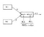
図11に示すように本実施形態では2段階のモーション補間を行っている。即ち図11においてM1は、図12(A)に示すように鉛直方向で下向きに移動体20が加速している場合に再生されるモーションデータを表す。またM2は、図12(B)に示すように鉛直方向で上向きに移動体20が加速している場合に再生されるモーションデータを表す。本実施形態では、まず、これらのM1、M2を補間レートα、βに基づいて補間し、MI1=M1×α+M2×βを得る。ここで補間レートα、βは、移動体20の鉛直方向の加速度に基づいて決まることになる。
【0050】
また図11においてM3は、図1のハンドル32を限界まで切った時のモーションデータを表す。本実施形態では、上記のように得られたMI1=M1×α+M2×βとM3とを、補間レートγ、σに基づいて補間し、MI2=MI1×γ+M3×σ=(M1×α+M2×β)γ+M3×σを得る。ここで補間レートγ、σは、ハンドル32の操舵角度により決まることになる。
【0051】
以上のようにして、本実施例では、移動体20の走行データ(鉛直方向の加速度)と操作データ(ハンドル32の操舵角度)が反映されたモーション再生を、モーションデータに要する記憶容量を最小限に抑えながら実現することが可能となる。
【0052】
図13に、鉛直方向の加速度に基づくモーション補間の一例を示す。図13において、G1〜G6は、鉛直方向で下向きの加速度を移動体20が有する場合に再生されるモーションデータの例である。G1〜G6では、キャラクタ22の姿勢が後側に傾き、手が伸びた状態になる。またH1〜H6は、鉛直方向で上向きの加速度を移動体20が有する場合に再生されるモーションデータの例である。H1〜H6では、キャラクタ22の姿勢が前傾になり、手が曲がった状態になる。
【0053】
本実施形態では、リアルタイムに得られる移動体の鉛直方向の加速度に基づいて、これらのモーションデータG1〜G6とH1〜H6とをフレーム毎に補間することでモーションデータI1〜I6を得て、このモーションデータI1〜I6を再生している。このようにすることで、予め用意されたモーションデータG1〜G6とH1〜H6に基づいて、移動体20の鉛直方向の加速度(走行データ)に応じた無数のモーションデータを得ることが可能となる。この結果、モーションデータに要する記憶容量を最小限に抑えながら、リアルな画像を生成できるようになる。
【0054】
なお図13では、移動体の走行データが鉛直方向の加速度である場合を例にとり説明した。特に自転車やバイクなどの搭乗体にキャラクタが搭乗するタイプのゲームにおいては、このように鉛直方向の加速度に基づいてキャラクタのモーションデータを補間することが望ましい。しかしながら、本発明における走行データはこれに限られものではなく、移動体の位置、方向、速度や、鉛直方向以外の加速度等、種々のものを採用できる。
【0055】
次に本実施形態の詳細な処理例について、図14、図15のフローチャートを用いて説明する。
【0056】
図14は、繋ぎモーションの再生(図8、図9、図10参照)に関するフローチャートである。
【0057】
まず初期化処理において、補正係数Kを1に初期化しておく(ステップS1)。なお補正係数Kは、補間レートα、βを補正するための係数であり、0≦K≦1の範囲で変化する。
【0058】
通常処理においては、まず当該フレームでの移動体20の位置を算出する(ステップS2)。次に、移動体20が図8に示す補正エリア54内に位置するか否か(ポイント56を通過したか否か)を判断する(ステップS3)。
【0059】
次に、K=0か否かを判断する(ステップS4)。そしてK=0でない場合には、K=K−m1の演算を行う(ステップS5)。ここで、m1は、0<m1<1の範囲にある定数である。例えば繋ぎモーションの再生(補間レートの補正)を10フレーム程度で行う場合には、m1=0.1になる。一方、K=0である場合にはステップS5の処理を行わずステップS6に移行する。
【0060】
次に、補間レートα、β(α+β=1、0≦α≦1、0≦β≦1)を補正係数Kを用いて下式(3)のように補正する(ステップS6)。
β=β×K
α=1−β (3)
このように補間レートα、βを補間することで(図10参照)、例えば図9のE1〜E6で説明したようにキャラクタ20の姿勢を徐々に直立状態に戻すことが可能になる。これによりE6からF1への移行時にモーションの飛びが発生するのが防止される。
【0061】
次に、補間されたモーションデータを再生する(ステップS8)。これにより当該フレームでの処理が終了する。
【0062】
ステップS3で移動体20が図8の補正エリア54内に位置しないと判断された場合には、移動体20が、モーション補間を行うエリアである第1のエリア50内に位置するか否かを判断する(ステップS9)。そして移動体20が第1のエリア50内に位置しない場合には、移動体20は、モーション補間を行わない第2のエリアに位置すると考えられる。したがって、この場合にはジャンプ用のモーションデータMJを選択し再生する(ステップS10、S8)。
【0063】
一方、ステップS9で移動体20が第1のエリア50内に位置すると判断された場合には、K=1か否かを判断する(ステップS11)。そしてK=1でない場合には、K=K−m2の演算を行う(ステップS12)。ここで、m2は、0<m2<1の範囲にある定数である。一方、K=1である場合にはステップS12の処理を行わずステップS6に移行する。
【0064】
ステップS11、S12の処理を設けたのは以下の理由による。即ち図8に示すように移動体20がジャンプした場合に、移動体20の着地点はプレーヤの操作等に依存するものであるため、予測することはできない。したがって、図8の第2のエリア52の右側のどの地点から再び第1のエリアが始まるかを予測することはできない。そして、移動体20が着地すると、その時点からモーション補間が有効になってしまい、着地した瞬間に図7のC6、D1に示すようなモーションの飛びが発生するおそれがある。即ち、着地した瞬間においてプレーヤが図1のハンドル32を右又は左に大きく切っていると、図7のC6、D1に示すようなモーションの飛びが発生する。
【0065】
本実施形態では、図14のステップS11、S12に示すように、ジャンプ後に再び第1のエリアに移動体が進入した場合に、K=1になるまでK=K+m2の補正がなされる。即ちモーション補間を行わない第2のエリアからモーション補間を行う第1のエリアに移動体が進入する場合に、第2のエリアのモーションデータと第1のエリアのモーションデータを繋ぐ繋ぎモーションが再生される。これによりプレーヤが違和感や不自然さを感じるのを有効に防止できるようになる。
【0066】
図15は、走行データに基づくモーション補間(図12(A)、(B)、図13参照)に関するフローチャートである。
【0067】
まず移動体の鉛直方向(Y方向)の速度の例えば過去60フレーム分の平均値VMYavを算出する(ステップT1)。移動体の速度は、前述の式(2)に示すように各フレーム毎に算出されている。
【0068】
次に、今回のフレームの移動体の鉛直方向の速度VMYを前述の式(2)に基づき算出する(ステップT2)。
【0069】
次に、鉛直方向の加速度AMYを下式(4)に基づいて算出する。
AMY=VMY−VMYav (4)
このようにすることで、図12(A)に示すように移動体20が岩などから降りた場合や、図12(B)に示すように移動体20が例えば岩などに上る場合に、移動体20の鉛直方向の加速度を容易に検出することが可能になる。
【0070】
次に、ステップT3で得られた鉛直方向の加速度AMYに基づいて、補間レートα、βを決定する(ステップT4)。例えば図12(A)に示すように移動体20が下方向に加速している場合にはαが大きくなり、図12(B)に示すように移動体20が上方向に加速している場合にはβが大きくなる。
【0071】
次に、ステップT4で得られた補間レートα、βに基づいて、図13に示されるようなモーション補間(M=M1×α+M2×β)を行う(ステップT5)。そして、得られたモーションを再生する(ステップT6)。
【0072】
以上の処理を各フレーム毎に行うことで、走行データに基づくモーション補間が可能になる。
【0073】
次に、本実施形態を実現できるハードウェアの構成の一例について図16を用いて説明する。同図に示す装置では、CPU1000、ROM1002、RAM1004、情報記憶媒体1006、音生成IC1008、画像生成IC1010、I/Oポート1012、1014が、システムバス1016により相互にデータ送受信可能に接続されている。そして前記画像生成IC1010にはディスプレイ1018が接続され、音生成IC1008にはスピーカ1020が接続され、I/Oポート1012にはコントロール装置1022が接続され、I/Oポート1014には通信装置1024が接続されている。
【0074】
情報記憶媒体1006は、プログラム、表示物を表現するための画像データ、音データ等が主に格納されるものである。例えば家庭用ゲーム装置ではゲームプログラム等を格納する情報記憶媒体としてCD−ROM、ゲームカセット、DVD等が用いられる。また業務用ゲーム装置ではROM等のメモリが用いられ、この場合には情報記憶媒体1006はROM1002になる。
【0075】
コントロール装置1022はゲームコントローラ、操作パネル等に相当するものであり、プレーヤがゲーム進行に応じて行う判断の結果を装置本体に入力するための装置である。
【0076】
情報記憶媒体1006に格納されるプログラム、ROM1002に格納されるシステムプログラム(装置本体の初期化情報等)、コントロール装置1022によって入力される信号等に従って、CPU1000は装置全体の制御や各種データ処理を行う。RAM1004はこのCPU1000の作業領域等として用いられる記憶手段であり、情報記憶媒体1006やROM1002の所与の内容、あるいはCPU1000の演算結果等が格納される。また本実施形態を実現するための論理的な構成を持つデータ構造(例えばモーションデータの構造)は、このRAM又は情報記憶媒体上に構築されることになる。
【0077】
更に、この種の装置には音生成IC1008と画像生成IC1010とが設けられていてゲーム音やゲーム画像の好適な出力が行えるようになっている。音生成IC1008は情報記憶媒体1006やROM1002に記憶される情報に基づいて効果音やバックグラウンド音楽等のゲーム音を生成する集積回路であり、生成されたゲーム音はスピーカ1020によって出力される。また、画像生成IC1010は、RAM1004、ROM1002、情報記憶媒体1006等から送られる画像情報に基づいてディスプレイ1018に出力するための画素情報を生成する集積回路である。なおディスプレイ1018として、いわゆるヘッドマウントディスプレイ(HMD)と呼ばれるものを使用することもできる。
【0078】
また、通信装置1024はゲーム装置内部で利用される各種の情報を外部とやりとりするものであり、他のゲーム装置と接続されてゲームプログラムに応じた所与の情報を送受したり、通信回線を介してゲームプログラム等の情報を送受することなどに利用される。
【0079】
そして図1〜図13で説明した種々の処理は、図14、図15のフローチャートに示した処理等を行うプログラムを格納した情報記憶媒体1006と、該プログラムに従って動作するCPU1000、画像生成IC1010、音生成IC1008等によって実現される。なお画像生成IC1010、音生成IC1008等で行われる処理は、CPU1000あるいは汎用のDSP等によりソフトウェア的に行ってもよい。
【0080】
さて前述した図1は、本実施形態を業務用ゲーム装置に適用した場合の例を示すものである。この場合、装置に内蔵されるシステム基板1106には、CPU、画像生成IC、音生成IC等が実装されている。そして、オブジェクト空間内で移動体を移動させる演算を行うための情報、モーション補間が行われる第1のエリアからモーション補間が行われない第2のエリアに移動体が進入する場合に、第1のエリアで再生するモーションデータと、第2のエリアで再生するモーションデータとを繋ぐ繋ぎモーションデータを再生するための情報、オブジェクト空間内の所与の視点において見える画像を生成するための情報、演算により得られた移動体の位置、方向、速度及び加速度の少なくとも1つを含む走行データに基づいてモーション補間を行い、補間により得られたモーションデータを再生するための情報等は、システム基板1106上の情報記憶媒体であるメモリ1108に格納される。以下、これらの情報を格納情報と呼ぶ。これらの格納情報は、上記の種々の処理を行うためのプログラムコード、画像情報、音情報、表示物の形状情報、テーブルデータ、リストデータ、プレーヤ情報等の少なくとも1つを含むものである。
【0081】
図17(A)に、本実施形態を家庭用のゲーム装置に適用した場合の例を示す。プレーヤはディスプレイ1200に映し出されたゲーム画像を見ながら、ゲームコントローラ1202、1204を操作してゲームを楽しむ。この場合、上記格納情報は、本体装置に着脱自在な情報記憶媒体であるCD−ROM1206、ICカード1208、1209等に格納されている。
【0082】
図17(B)に、ホスト装置1300と、このホスト装置1300と通信回線1302を介して接続される端末1304-1〜1304-nとを含むゲーム装置に本実施形態を適用した場合の例を示す。この場合、上記格納情報は、例えばホスト装置1300が制御可能な磁気ディスク装置、磁気テープ装置、メモリ等の情報記憶媒体1306に格納されている。端末1304-1〜1304-nが、CPU、画像生成IC、音生成ICを有し、スタンドアロンでゲーム画像、ゲーム音を生成できるものである場合には、ホスト装置1300からは、ゲーム画像、ゲーム音を生成するためのゲームプログラム等が端末1304-1〜1304-nに配送される。一方、スタンドアロンで生成できない場合には、ホスト装置1300がゲーム画像、ゲーム音を生成し、これを端末1304-1〜1304-nに伝送し端末において出力することになる。
【0083】
なお本発明は、上記実施形態で説明したものに限らず、種々の変形実施が可能である。
【0084】
例えば繋ぎモーションを再生する手法は、図9、図10、図14等で説明した手法が好ましいが、本発明はこれに限らず種々の変形実施が可能である。例えば、予め繋ぎ用のモーションデータを用意しておいて、これを再生するようにしてもよい。
【0085】
また移動体は、搭乗体を含まないキャラクタのみのものであってもよいし、キャラクタを含まない搭乗体のみでのものであってもよい。
【0086】
また走行データに基づきモーション補間を行う手法も本実施形態で説明したものに限らず、種々の変形実施が可能である。
【0087】
また本実施形態では自転車の競争ゲームに本発明を適用した場合について説明したが、本発明はこれに限らず種々のゲーム(他の競争ゲーム、スポーツゲーム、対戦ゲーム、ロールプレイングゲーム、シューティングゲーム等)に適用できる。
【0088】
また本発明は、家庭用、業務用のゲーム装置のみならず、シミュレータ、多数のプレーヤが参加する大型アトラクション装置、パーソナルコンピュータ、マルチメディア端末、ゲーム画像を生成するシステム基板等の種々の画像生成装置にも適用できる。
【0089】
【図面の簡単な説明】
【図1】本実施形態の画像生成装置の外観図の一例である。
【図2】本実施形態の画像生成装置の機能ブロック図の一例である。
【図3】本実施形態により生成される画像の例を示す図である。
【図4】モーション補間について説明するための図である。
【図5】モーション補間について説明するための図である。
【図6】繋ぎモーションを再生しない場合の問題点について説明するための図である。
【図7】繋ぎモーションを再生しない場合の問題点について説明するための図である。
【図8】繋ぎモーションを再生する手法について説明するための図である。
【図9】繋ぎモーションを再生する手法について説明するための図である。
【図10】補間レートを補正する手法について説明するための図である。
【図11】2段階のモーション補間を行う手法について説明するための図である。
【図12】図12(A)、(B)は、走行データ(鉛直方向の加速度)に基づくモーション補間について説明するための図である。
【図13】走行データ(鉛直方向の加速度)に基づくモーション補間について説明するための図である。
【図14】本実施形態の詳細な処理例を説明するためのフローチャートである。
【図15】本実施形態の詳細な処理例を説明するためのフローチャートである。
【図16】本実施形態を実現できるハードウェアの構成の一例を示す図である。
【図17】図17(A)、(B)は、本実施形態が適用される種々の形態の装置の例を示す図である。
【符号の説明】
10 操作部
12 表示部
16 ライディング筐体
17 サドル
18 ディスプレイ
20 移動体
22 キャラクタ
30 ペダル
32 ハンドル
40 コース
50 第1のエリア
52 第2のエリア
54 補正エリア
56 ポイント
100 処理部
110 ゲーム演算部
112 移動体演算部
116 モーションデータ再生部
120 モーションデータ記憶部
150 画像生成部
190 情報記憶媒体[0001]
BACKGROUND OF THE INVENTION
The present invention relates to an image generation apparatus and an information storage medium that generate an image at a given viewpoint in an object space.
[0002]
[Background Art and Problems to be Solved by the Invention]
2. Description of the Related Art Conventionally, image generation apparatuses that arrange a plurality of objects in an object space that is a virtual three-dimensional space and generate an image that can be viewed from a given viewpoint in the object space have been developed and put into practical use. It is popular as a way to experience reality. Taking an image generation apparatus that can enjoy a motorcycle game as an example, a player enjoys a three-dimensional game by running a motorcycle operated by the player in the object space.
[0003]
Now, such an image generation apparatus has a problem of improving the virtual reality of the player. For this reason, for example, not only a motorcycle but also a character riding a motorcycle is desired to be operated in a more realistic manner. The motion of the character can be expressed by preparing motion data describing the motion of the character in advance and reproducing the motion data. At this time, in order to further improve the virtual reality, it is desirable to cause the character to perform a movement reflecting operation data from the player.
[0004]
However, it has been found that there are areas where it is not desirable to reflect the operation data from the player depending on the area where the motorcycle runs.
[0005]
It has also been found that the virtual reality cannot be achieved by only reflecting the operation data from the player in the movement of the character.
[0006]
The present invention has been made in view of the above problems, and an object of the present invention is to provide an image generation apparatus and an information storage medium that enable reproduction of real and smooth motion data. .
[0007]
[Means for Solving the Problems]
In order to solve the above-described problems, the present invention provides an image generation apparatus that generates an image at a given viewpoint in an object space, a unit that performs an operation of moving a moving object in the object space, and motion interpolation When the moving body enters the second area where motion interpolation is not performed from the first area where the motion is performed, the motion data reproduced in the first area and the motion data reproduced in the second area It is characterized by including means for reproducing connected motion data and means for generating an image that can be seen at a given viewpoint in the object space.
[0008]
According to the present invention, when the moving body moves in the first area, motion interpolation is performed, thereby generating a realistic image. On the other hand, according to the present invention, it is possible to provide a second area in which motion interpolation is not performed. When providing such first and second areas in the object space, if no measures are taken, an unnatural image is generated when the moving body enters the second area from the first area. There is a risk of being. However, according to the present invention, when the moving body enters the second area from the first area, the connection motion data that connects the motion data to be reproduced in these areas is reproduced. As a result, such an unnatural image can be prevented from being generated. That is, according to the present invention, it is possible to provide a first area where motion interpolation is performed and a second area where motion interpolation is not performed, and an image that does not feel uncomfortable even when a moving object moves between these areas. Will be able to provide.
[0009]
Further, the present invention is characterized in that the joint motion data is reproduced by correcting an interpolation rate of motion interpolation performed in the first area. By doing so, it is possible to reproduce the connected motion data by a simple process of simply correcting the interpolation rate.
[0010]
Further, the invention is characterized in that the correction of the interpolation rate is started when the moving body passes a given point. By doing in this way, before a mobile body approachs from the 1st area to the 2nd area, it becomes possible to reproduce connection motion data reliably.
[0011]
The present invention also provides motion data to be reproduced in the second area when the mobile body enters the first area in which motion interpolation is performed from the second area in which motion interpolation is not performed, It is characterized in that the motion data connected to the motion data to be played back in the area is played back. In this way, even when the moving body enters the first area from the second area, it is possible to prevent an unnatural image from being generated.
[0012]
Further, the present invention is characterized in that motion interpolation is performed based on at least one of operation data and travel data of the moving body. By doing so, it is possible to reproduce realistic motion data reflecting operation data and traveling data of the moving body, and virtual reality can be improved.
[0013]
The present invention also relates to an image generation apparatus for generating an image at a given viewpoint in an object space, the means for performing an operation for moving the moving body in the object space, and the moving body obtained by the operation. Motion interpolation is performed based on running data including at least one of position, direction, velocity, and acceleration, and means for reproducing the motion data obtained by the interpolation and an image that can be seen at a given viewpoint in the object space are generated. Means.
[0014]
According to the present invention, motion interpolation is performed based on travel data of a moving object. For this reason, realistic motion data reflecting the traveling data of the moving object can be reproduced. In particular, according to the present invention, when a moving body travels on a course rich in changes, motion data reflecting traveling data of the moving body that changes in real time depending on the course situation can be reproduced. For this reason, the virtual reality can be further improved.
[0015]
According to the present invention, the travel data includes acceleration in the vertical direction of the moving body, the moving body includes a vehicle and a character riding on the vehicle, and the movement of the character based on the acceleration in the vertical direction It is characterized by performing motion interpolation. By doing so, for example, when the moving body moves on a course with up-down, it becomes possible to express the movement of the character that changes in accordance with up-down, and the realism of the image can be enhanced.
[0016]
Further, the present invention is characterized in that the moving body includes a rider and a character riding on the rider, and moves the character by reproducing motion data. By doing so, it becomes possible to change the motion of the character riding on the moving body realistically and smoothly, and it is possible to provide an optimal image for a bicycle game, a motorcycle game, or the like.
[0017]
DETAILED DESCRIPTION OF THE INVENTION
Hereinafter, preferred embodiments of the present invention will be described with reference to the drawings. In the following, a case where the present invention is applied to a bicycle game will be described as an example. However, the present invention is not limited to this.
[0018]
FIG. 1 shows an example of an external view when the image generation apparatus of the present embodiment is applied to a business game apparatus.
[0019]
Here, the riding
[0020]
FIG. 2 shows an example of a functional block diagram of the image generation apparatus of the present embodiment.
[0021]
Here, the
[0022]
The
[0023]
The
[0024]
The
[0025]
Here, the
[0026]
The motion data storage unit 120 stores various motion data. This motion data is stored in the
[0027]
The
[0028]
The
[0029]
Here, the moving
[0030]
For example, assume that the position of the moving body in the (k-1) frame is PMk-1, the speed is VMk-1, the acceleration is AMk-1, and the time of one frame is Δt. Then, the position PMk and the speed VMk of the moving body in k frames are obtained, for example, by the following equations (1) and (2).
PMk = PMk-1 + VMk-1 * .DELTA.t (1)
VMk = VMk-1 + AMk-1 * .DELTA.t (2)
The motion data reproduction unit 116 performs processing for reproducing the motion data stored in the motion data storage unit 120. In addition, the motion data reproducing unit 116 performs a process of interpolating the motion data stored in the motion data storage unit 120 and reproducing the interpolated motion data.
[0031]
FIG. 3 shows an example of an image generated by this embodiment. The player operates the moving
[0032]
In the present embodiment, not only the motion data stored in the motion data storage unit 120 is reproduced as it is, but also processing for interpolating and reproducing two or more motion data stored in the motion data storage unit 120 is performed.
[0033]
The principle of motion interpolation (interpolation of motion data) will be described with reference to FIGS. Here, the motion interpolation means that two or more pieces of motion data (position data and direction data for each part object frame constituting the object) are interpolated at a given interpolation rate to generate new motion data. . For example, in FIG. 4, the motion of B3 is generated by interpolating the motion of B1 and the motion of B2.
[0034]
More specifically, for example, the process shown in FIG. 5 is performed to realize motion interpolation. For example, position data of a part object (neck, hand, foot, etc.) included in the first motion data, direction (rotation) data is T1, R1, and position data of the part object included in the second motion data, The direction data are T2 and R2. Also, the interpolation rate for the first motion data is α, and the interpolation rate for the second motion data is β. Then, new motion data whose position data is T1 × α + T2 × β and whose direction data is R1 × α + R2 × β is generated and reproduced by interpolation. In this embodiment, this motion interpolation is performed for each frame (time).
[0035]
In the present embodiment, the above-described interpolation rates α and β are determined based on operation data, traveling data of the moving body, and the like.
[0036]
By performing such motion interpolation, it is not necessary to prepare all the motion data corresponding to the operation data in advance. This is because motion data corresponding to the operation data can be generated by interpolation based on the reference motion data.
[0037]
However, depending on the game situation, motion interpolation may not be necessary. For example, as shown in FIG. 6, when the moving
[0038]
That is, in the first area 50, for example, if the player turns the
[0039]
However, it has been found that the following problem occurs when the moving
[0040]
For example, in the first area 50, motion data generated by interpolation as shown by C1 to C6 in FIG. 7 is reproduced. On the other hand, in the second area 52, motion data (jump motion data) prepared in advance as shown in D1 to D4 is reproduced without interpolation. When the moving
[0041]
In this case, the inclination angle of the
[0042]
In order to solve such a problem, the present embodiment has the following features. That is, the first feature of the present embodiment is that when a moving body enters the second area where motion interpolation is not performed from the first area where motion interpolation is performed, motion data reproduced in the first area and The connection motion data connected to the motion data to be played back in the second area is played back.
[0043]
More specifically, the following processing is performed. That is, as shown in FIG. 8, a
[0044]
An example of motion data in this case is shown in FIG. In the first area 50, motion data generated by interpolation as shown by E1 to E6 in FIG. 9 is reproduced. On the other hand, in the second area 52, motion data prepared in advance as shown in F1 to F4 is reproduced without interpolation. 7 differs from FIG. 7 in that the
[0045]
That is, when the moving
[0046]
Note that, in the present embodiment, the playback of the joint motion data is realized by correcting the interpolation rate of the motion interpolation performed in the first area 50. For example, as shown in FIG. 10, in the first area 50, the two motion data M1 and M2 are interpolated according to a relational expression expressed as M1 × α + M2 × β. Here, α and β are interpolation rates. In this embodiment, when the moving
[0047]
The second feature of the present embodiment is that travel data such as the position, direction, speed (including angular velocity) and acceleration (including angular acceleration) of the moving body obtained from the moving
[0048]
More specifically, in the present embodiment, the following processing is performed.
[0049]
As shown in FIG. 11, in this embodiment, two-stage motion interpolation is performed. That is, in FIG. 11, M1 represents the motion data reproduced when the moving
[0050]
In FIG. 11, M3 represents motion data when the
[0051]
As described above, in this embodiment, the motion reproduction reflecting the traveling data (vertical acceleration) and the operation data (steering angle of the steering wheel 32) of the moving
[0052]
FIG. 13 shows an example of motion interpolation based on vertical acceleration. In FIG. 13, G1 to G6 are examples of motion data reproduced when the moving
[0053]
In the present embodiment, based on the vertical acceleration of the moving body obtained in real time, the motion data G1 to G6 and H1 to H6 are interpolated for each frame to obtain the motion data I1 to I6. The motion data I1 to I6 are reproduced. By doing in this way, based on the motion data G1 to G6 and H1 to H6 prepared in advance, it becomes possible to obtain countless motion data according to the acceleration (travel data) in the vertical direction of the moving
[0054]
In FIG. 13, the case where the traveling data of the moving body is the acceleration in the vertical direction has been described as an example. In particular, in a game of a type in which a character rides on a vehicle such as a bicycle or a motorcycle, it is desirable to interpolate the motion data of the character based on the acceleration in the vertical direction as described above. However, the travel data in the present invention is not limited to this, and various data such as the position, direction, and speed of the moving body and acceleration other than the vertical direction can be adopted.
[0055]
Next, a detailed processing example of the present embodiment will be described with reference to the flowcharts of FIGS.
[0056]
FIG. 14 is a flowchart relating to the playback of the joint motion (see FIGS. 8, 9, and 10).
[0057]
First, in the initialization process, the correction coefficient K is initialized to 1 (step S1). The correction coefficient K is a coefficient for correcting the interpolation rates α and β, and changes in the range of 0 ≦ K ≦ 1.
[0058]
In the normal process, first, the position of the moving
[0059]
Next, it is determined whether or not K = 0 (step S4). If K is not 0, K = K−m1 is calculated (step S5). Here, m1 is a constant in the range of 0 <m1 <1. For example, when the joint motion is reproduced (interpolation rate correction) in about 10 frames, m1 = 0.1. On the other hand, if K = 0, the process proceeds to step S6 without performing the process of step S5.
[0060]
Next, the interpolation rates α and β (α + β = 1, 0 ≦ α ≦ 1, 0 ≦ β ≦ 1) are corrected as shown in the following expression (3) using the correction coefficient K (step S6).
β = β × K
α = 1−β (3)
By interpolating the interpolation rates α and β in this way (see FIG. 10), the posture of the
[0061]
Next, the interpolated motion data is reproduced (step S8). As a result, the processing in the frame ends.
[0062]
If it is determined in step S3 that the moving
[0063]
On the other hand, if it is determined in step S9 that the moving
[0064]
The reason why the processes of steps S11 and S12 are provided is as follows. That is, when the moving
[0065]
In the present embodiment, as shown in steps S11 and S12 of FIG. 14, when the moving body enters the first area again after the jump, K = K + m2 is corrected until K = 1. In other words, when a moving body enters the first area where motion interpolation is performed from the second area where motion interpolation is not performed, the connection motion connecting the motion data of the second area and the motion data of the first area is reproduced. The This effectively prevents the player from feeling uncomfortable or unnatural.
[0066]
FIG. 15 is a flowchart regarding motion interpolation (see FIGS. 12A, 12B, and 13) based on travel data.
[0067]
First, for example, an average value VMYav for the past 60 frames of the velocity of the moving body in the vertical direction (Y direction) is calculated (step T1). The speed of the moving body is calculated for each frame as shown in the above equation (2).
[0068]
Next, the vertical velocity VMY of the moving body of the current frame is calculated based on the above-described equation (2) (step T2).
[0069]
Next, the vertical acceleration AMY is calculated based on the following equation (4).
AMY = VMY-VMYav (4)
By doing so, when the moving
[0070]
Next, the interpolation rates α and β are determined based on the vertical acceleration AMY obtained in step T3 (step T4). For example, when the moving
[0071]
Next, based on the interpolation rates α and β obtained in step T4, motion interpolation (M = M1 × α + M2 × β) as shown in FIG. 13 is performed (step T5). Then, the obtained motion is reproduced (step T6).
[0072]
By performing the above processing for each frame, motion interpolation based on running data becomes possible.
[0073]
Next, an example of a hardware configuration capable of realizing the present embodiment will be described with reference to FIG. In the apparatus shown in the figure, a
[0074]
The
[0075]
The
[0076]
In accordance with a program stored in the
[0077]
Further, this type of apparatus is provided with a
[0078]
The
[0079]
The various processes described with reference to FIGS. 1 to 13 include an
[0080]
FIG. 1 described above shows an example in which the present embodiment is applied to an arcade game machine. In this case, a CPU, an image generation IC, a sound generation IC, and the like are mounted on a
[0081]
FIG. 17A shows an example in which the present embodiment is applied to a home game device. The player enjoys the game by operating the
[0082]
FIG. 17B shows an example in which the present embodiment is applied to a game device including a
[0083]
The present invention is not limited to that described in the above embodiment, and various modifications can be made.
[0084]
For example, the technique described in FIGS. 9, 10, 14, and the like is preferable as the technique for reproducing the joint motion, but the present invention is not limited to this, and various modifications can be implemented. For example, motion data for connection may be prepared in advance and played back.
[0085]
In addition, the moving body may be only a character that does not include a boarding body, or may be only a boarding body that does not include a character.
[0086]
Further, the method of performing motion interpolation based on the travel data is not limited to that described in the present embodiment, and various modifications can be made.
[0087]
In the present embodiment, the case where the present invention is applied to a bicycle competition game has been described. However, the present invention is not limited to this, and various games (other competition games, sports games, battle games, role playing games, shooting games, etc.) ).
[0088]
The present invention is not limited to home and business game devices, but also various image generation devices such as a simulator, a large attraction device in which a large number of players participate, a personal computer, a multimedia terminal, and a system board for generating game images. It can also be applied to.
[0089]
[Brief description of the drawings]
FIG. 1 is an example of an external view of an image generation apparatus according to an embodiment.
FIG. 2 is an example of a functional block diagram of the image generation apparatus of the present embodiment.
FIG. 3 is a diagram illustrating an example of an image generated according to the present embodiment.
FIG. 4 is a diagram for explaining motion interpolation.
FIG. 5 is a diagram for explaining motion interpolation;
FIG. 6 is a diagram for explaining a problem that occurs when a joint motion is not reproduced.
[Fig. 7] Fig. 7 is a diagram for explaining a problem when a joint motion is not reproduced.
[Fig. 8] Fig. 8 is a diagram for explaining a technique for reproducing a joint motion.
[Fig. 9] Fig. 9 is a diagram for explaining a technique for reproducing a joint motion.
FIG. 10 is a diagram for explaining a method of correcting an interpolation rate.
FIG. 11 is a diagram for explaining a technique for performing two-stage motion interpolation.
FIGS. 12A and 12B are diagrams for explaining motion interpolation based on travel data (acceleration in the vertical direction).
FIG. 13 is a diagram for explaining motion interpolation based on travel data (acceleration in the vertical direction).
FIG. 14 is a flowchart for explaining a detailed processing example of the present embodiment;
FIG. 15 is a flowchart for explaining a detailed processing example of the present embodiment;
FIG. 16 is a diagram illustrating an example of a hardware configuration capable of realizing the present embodiment.
FIGS. 17A and 17B are diagrams illustrating examples of various types of apparatuses to which the present embodiment is applied.
[Explanation of symbols]
10 Operation part
12 Display section
16 Riding housing
17 saddle
18 display
20 Mobile
22 characters
30 pedals
32 Handle
40 courses
50 1st area
52 2nd area
54 Correction Area
56 points
100 processor
110 Game calculation part
112 Mobile object calculation unit
116 Motion data playback unit
120 Motion data storage
150 Image generator
190 Information storage media
Claims (5)
Translated fromJapaneseオブジェクト空間内で移動体を移動させる演算を行う移動体演算手段と、
前記移動体のモーションデータとして、第1のモーションを示す第1のモーションデータと、前記第1のモーションから変化した変化後の第2のモーションを示す第2のモーションデータと、前記第1のモーションから変化する第3のモーションを示す第3のモーションデータと、を記憶する記憶手段と、
前記移動体のモーションデータを再生するモーションデータ再生手段と、
オブジェクト空間内の所与の視点において見える画像を生成する画像生成手段とを含み、
前記モーションデータ再生手段が、
前記移動体が第1のエリアに存在する場合に、操作部からの操作入力に応じた補間レートで、前記第1のモーションデータと前記第2のモーションデータとをモーション補間したモーションデータを再生し、前記移動体が第2のエリアに存在する場合に、モーション補間せずに前記第3のモーションデータを再生し、前記第1のエリアと前記第2のエリアとの間の補正エリアに前記移動体が存在する場合に、前記移動体が前記第2のエリアに到達するまでに前記第1のモーションデータが再生されるように前記第1のモーションデータをモーション補間する割合を徐々に大きくする補正を行った補間レートで、前記第1のモーションデータと前記第2のモーションデータとをモーション補間したモーションデータを再生することを特徴とする画像生成装置。An image generation device that generates an image at a given viewpoint in an object space,
A moving body computing means for performing a computation for moving the moving body in the object space;
As the motion data of the moving body, first motion data indicating a first motion, second motion data indicating a second motion after a change changed from the first motion, and the first motion Storage means for storing third motion data indicating a third motion that changes from
Motion data reproducing means for reproducing motion data of the moving body;
Image generating means for generating an image visible at a given viewpoint in the object space,
The motion data reproduction means is
When the moving body is present in the first area, the motion data obtained by interpolating the first motion data and the second motion data at the interpolation rate according to the operation input from the operation unit is reproduced. When the moving body exists in the second area, the third motion data is reproduced without motion interpolation, and the movement is performed to the correction area betweenthe first area and the second area.Correction that gradually increases the rate of motion interpolation of the first motion data so that the first motion data is reproduced before the moving body reaches the second area when the body existsin the interpolation rate it was, characterized in that it reproducesthe first motion data and the second motiondata and motion data and motion interpolation Image generating device.
前記記憶手段が、
第4のモーションデータと第5のモーションデータとを更に記憶し、
前記モーションデータ再生手段が、
前記移動体演算手段の演算により得られた前記移動体の位置、方向、速度及び加速度の少なくとも1つを含む走行データに応じた補間レートで前記第4のモーションデータと前記第5のモーションデータとをモーション補間して前記第1のモーションデータを得ることを特徴とする画像生成装置。In claim1 ,
The storage means
Further storing the fourth motion data and the fifth motion data,
The motion data reproduction means is
The fourth motion data and the fifth motion data at an interpolation rate corresponding to travel data including at least one of the position, direction, speed, and acceleration of the mobile body obtained by the computation of the mobile body computing meansmotion interpolationto image generation apparatus according to claim Rukotoobtainthe first motion data.
前記走行データが前記移動体の鉛直方向の加速度であり、前記移動体が搭乗体と該搭乗体に搭乗するキャラクタとを含み、
前記モーションデータ再生手段が、
前記鉛直方向の加速度に応じた補間レートで前記第4のモーションデータと前記第5のモーションデータとをモーション補間して前記第1のモーションデータを得ることを特徴とする画像生成装置。In claim2 ,
The travel data is acceleration in the vertical direction of the mobile body, and the mobile body includes a rider and a character riding on the rider,
The motion data reproduction means is
An image generating apparatus characterized in thatthe first motion data is obtained by performing motion interpolationbetween the fourth motion data and the fifth motion data at an interpolation rate corresponding to the acceleration in the vertical direction.
前記移動体が、搭乗体と該搭乗体に搭乗するキャラクタとを含み、前記モーションデータ再生手段が、モーションデータの再生により該キャラクタを動作させることを特徴とする画像生成装置。In any one of Claims 1 thru | or3 ,
The image generating apparatus, wherein the moving body includes a vehicle and a character riding on the vehicle, and the motion data reproducing means operates the character by reproducing the motion data.
オブジェクト空間内で移動体を移動させる演算を行う移動体演算手段と、
前記移動体のモーションデータとして、第1のモーションを示す第1のモーションデータと、前記第1のモーションから変化した変化後の第2のモーションを示す第2のモーションデータと、前記第1のモーションから変化する第3のモーションを示す第3のモーションデータと、を記憶する記憶手段と、
前記移動体のモーションデータを再生するモーションデータ再生手段と、
オブジェクト空間内の所与の視点において見える画像を生成する画像生成手段としてコンピュータを機能させ、
前記モーションデータ再生手段が、
前記移動体が第1のエリアに存在する場合に、操作部からの操作入力に応じた補間レートで、前記第1のモーションデータと前記第2のモーションデータとをモーション補間したモーションデータを再生し、前記移動体が第2のエリアに存在する場合に、モーション補間せずに前記第3のモーションデータを再生し、前記第1のエリアと前記第2のエリアとの間の補正エリアに前記移動体が存在する場合に、前記移動体が前記第2のエリアに到達するまでに前記第1のモーションデータが再生されるように前記第1のモーションデータをモーション補間する割合を徐々に大きくする補正を行った補間レートで、前記第1のモーションデータと前記第2のモーションデータとをモーション補間したモーションデータを再生することを特徴とするプログラムを記憶した情報記憶媒体。A computer-readable information storage medium for generating an image at a given viewpoint in an object space,
A moving body computing means for performing a computation for moving the moving body in the object space;
As the motion data of the moving body, first motion data indicating a first motion, second motion data indicating a second motion after a change changed from the first motion, and the first motion Storage means for storing third motion data indicating a third motion that changes from
Motion data reproducing means for reproducing motion data of the moving body;
Causing the computer to function as an image generating means for generating an image that can be seen at a given viewpoint in the object space;
The motion data reproduction means is
When the moving body is present in the first area, the motion data obtained by interpolating the first motion data and the second motion data at the interpolation rate according to the operation input from the operation unit is reproduced. When the moving body exists in the second area, the third motion data is reproduced without motion interpolation, and the movement is performed to the correction area betweenthe first area and the second area.Correction that gradually increases the rate of motion interpolation of the first motion data so that the first motion data is reproduced before the moving body reaches the second area when the body existsin the interpolation rate it was, characterized in that it reproducesthe first motion data and the second motiondata and motion data and motion interpolation Stored information storage medium the program.
Priority Applications (1)
| Application Number | Priority Date | Filing Date | Title |
|---|---|---|---|
| JP35214097AJP4108167B2 (en) | 1997-12-05 | 1997-12-05 | Image generating apparatus and information storage medium |
Applications Claiming Priority (1)
| Application Number | Priority Date | Filing Date | Title |
|---|---|---|---|
| JP35214097AJP4108167B2 (en) | 1997-12-05 | 1997-12-05 | Image generating apparatus and information storage medium |
Publications (3)
| Publication Number | Publication Date |
|---|---|
| JPH11175753A JPH11175753A (en) | 1999-07-02 |
| JPH11175753A5 JPH11175753A5 (en) | 2005-07-21 |
| JP4108167B2true JP4108167B2 (en) | 2008-06-25 |
Family
ID=18422057
Family Applications (1)
| Application Number | Title | Priority Date | Filing Date |
|---|---|---|---|
| JP35214097AExpired - LifetimeJP4108167B2 (en) | 1997-12-05 | 1997-12-05 | Image generating apparatus and information storage medium |
Country Status (1)
| Country | Link |
|---|---|
| JP (1) | JP4108167B2 (en) |
Families Citing this family (2)
| Publication number | Priority date | Publication date | Assignee | Title |
|---|---|---|---|---|
| JP2003085592A (en)* | 2001-09-10 | 2003-03-20 | Namco Ltd | Image generation system, program, and information storage medium |
| JP7312737B2 (en)* | 2020-11-19 | 2023-07-21 | 株式会社コーエーテクモゲームス | Program, information processing method and information processing apparatus |
- 1997
- 1997-12-05JPJP35214097Apatent/JP4108167B2/ennot_activeExpired - Lifetime
Also Published As
| Publication number | Publication date |
|---|---|
| JPH11175753A (en) | 1999-07-02 |
Similar Documents
| Publication | Publication Date | Title |
|---|---|---|
| US6217449B1 (en) | Image generating device and information storage medium | |
| KR100566751B1 (en) | Image generating apparatus and image generating method | |
| US20030207704A1 (en) | Game machine and game program | |
| JP2000262738A (en) | Game device and information storage medium | |
| JP4056021B2 (en) | Image generating apparatus and information storage medium | |
| JP4114822B2 (en) | Image generating apparatus and information storage medium | |
| JP4108167B2 (en) | Image generating apparatus and information storage medium | |
| JP3123957B2 (en) | Three-dimensional game device and information storage medium | |
| JP4397410B2 (en) | Image generating apparatus and information storage medium | |
| JP4036509B2 (en) | Image generating apparatus and information storage medium | |
| JP4036508B2 (en) | Image generating apparatus and information storage medium | |
| JP2001273525A (en) | Entertainment device, storage medium, and object display method | |
| JP3127137B2 (en) | Image generation device and information storage medium | |
| JP3753338B2 (en) | 3D simulator apparatus and image composition method | |
| JP2000331184A (en) | Image generation device and information storage medium | |
| JP4233065B2 (en) | GAME DEVICE AND INFORMATION STORAGE MEDIUM | |
| JP2007181713A (en) | GAME DEVICE AND INFORMATION STORAGE MEDIUM | |
| JP4042926B2 (en) | Image generating apparatus and information storage medium | |
| JP4560532B2 (en) | Image generating apparatus and information storage medium | |
| JP4001434B2 (en) | GAME DEVICE AND INFORMATION STORAGE MEDIUM | |
| JP4251657B2 (en) | Image generating apparatus and information storage medium | |
| JP2000153057A (en) | Game device and information storage medium | |
| JP4088169B2 (en) | Image generating apparatus and information storage medium | |
| JP3898361B2 (en) | GAME DEVICE AND INFORMATION STORAGE MEDIUM | |
| JP3990068B2 (en) | GAME DEVICE AND INFORMATION STORAGE MEDIUM |
Legal Events
| Date | Code | Title | Description |
|---|---|---|---|
| A521 | Written amendment | Free format text:JAPANESE INTERMEDIATE CODE: A523 Effective date:20041202 | |
| A621 | Written request for application examination | Free format text:JAPANESE INTERMEDIATE CODE: A621 Effective date:20041202 | |
| A977 | Report on retrieval | Free format text:JAPANESE INTERMEDIATE CODE: A971007 Effective date:20070724 | |
| A131 | Notification of reasons for refusal | Free format text:JAPANESE INTERMEDIATE CODE: A131 Effective date:20070801 | |
| A521 | Written amendment | Free format text:JAPANESE INTERMEDIATE CODE: A523 Effective date:20070928 | |
| A02 | Decision of refusal | Free format text:JAPANESE INTERMEDIATE CODE: A02 Effective date:20071107 | |
| A521 | Written amendment | Free format text:JAPANESE INTERMEDIATE CODE: A523 Effective date:20071225 | |
| A911 | Transfer of reconsideration by examiner before appeal (zenchi) | Free format text:JAPANESE INTERMEDIATE CODE: A911 Effective date:20080219 | |
| TRDD | Decision of grant or rejection written | ||
| A01 | Written decision to grant a patent or to grant a registration (utility model) | Free format text:JAPANESE INTERMEDIATE CODE: A01 Effective date:20080319 | |
| A61 | First payment of annual fees (during grant procedure) | Free format text:JAPANESE INTERMEDIATE CODE: A61 Effective date:20080402 | |
| FPAY | Renewal fee payment (event date is renewal date of database) | Free format text:PAYMENT UNTIL: 20110411 Year of fee payment:3 | |
| R150 | Certificate of patent or registration of utility model | Free format text:JAPANESE INTERMEDIATE CODE: R150 | |
| FPAY | Renewal fee payment (event date is renewal date of database) | Free format text:PAYMENT UNTIL: 20110411 Year of fee payment:3 | |
| FPAY | Renewal fee payment (event date is renewal date of database) | Free format text:PAYMENT UNTIL: 20110411 Year of fee payment:3 | |
| FPAY | Renewal fee payment (event date is renewal date of database) | Free format text:PAYMENT UNTIL: 20120411 Year of fee payment:4 | |
| FPAY | Renewal fee payment (event date is renewal date of database) | Free format text:PAYMENT UNTIL: 20130411 Year of fee payment:5 | |
| FPAY | Renewal fee payment (event date is renewal date of database) | Free format text:PAYMENT UNTIL: 20130411 Year of fee payment:5 | |
| FPAY | Renewal fee payment (event date is renewal date of database) | Free format text:PAYMENT UNTIL: 20140411 Year of fee payment:6 | |
| R250 | Receipt of annual fees | Free format text:JAPANESE INTERMEDIATE CODE: R250 | |
| R250 | Receipt of annual fees | Free format text:JAPANESE INTERMEDIATE CODE: R250 | |
| S531 | Written request for registration of change of domicile | Free format text:JAPANESE INTERMEDIATE CODE: R313531 | |
| R360 | Written notification for declining of transfer of rights | Free format text:JAPANESE INTERMEDIATE CODE: R360 | |
| S533 | Written request for registration of change of name | Free format text:JAPANESE INTERMEDIATE CODE: R313533 | |
| R370 | Written measure of declining of transfer procedure | Free format text:JAPANESE INTERMEDIATE CODE: R370 | |
| R350 | Written notification of registration of transfer | Free format text:JAPANESE INTERMEDIATE CODE: R350 | |
| S531 | Written request for registration of change of domicile | Free format text:JAPANESE INTERMEDIATE CODE: R313531 | |
| R350 | Written notification of registration of transfer | Free format text:JAPANESE INTERMEDIATE CODE: R350 | |
| R250 | Receipt of annual fees | Free format text:JAPANESE INTERMEDIATE CODE: R250 | |
| EXPY | Cancellation because of completion of term |