JP4107568B2 - Imaging device - Google Patents
Imaging deviceDownload PDFInfo
- Publication number
- JP4107568B2 JP4107568B2JP2002122318AJP2002122318AJP4107568B2JP 4107568 B2JP4107568 B2JP 4107568B2JP 2002122318 AJP2002122318 AJP 2002122318AJP 2002122318 AJP2002122318 AJP 2002122318AJP 4107568 B2JP4107568 B2JP 4107568B2
- Authority
- JP
- Japan
- Prior art keywords
- control unit
- finger
- touch panel
- imaging
- area
- Prior art date
- Legal status (The legal status is an assumption and is not a legal conclusion. Google has not performed a legal analysis and makes no representation as to the accuracy of the status listed.)
- Expired - Lifetime
Links
Images


Landscapes
- Studio Devices (AREA)
- Position Input By Displaying (AREA)
Description
Translated fromJapanese【0001】
【発明が属する技術分野】
本発明は、撮像装置に関し、さらに詳しくは、撮像装置の一つであるデジタルカメラに適用されるタッチパネルでの触指状態を判別して操作内容を設定するための構成に関する。
【0002】
【従来の技術】
撮影装置であるカメラには、銀塩フィルムを用いるものやこのフィルムを用いないで撮影画像を電子的・磁気的に記録保存できるデジタルカメラがある。
デジタルカメラは、撮影対象の視認のためのファインダを設けるほかに、撮影画像の確認や撮影モードなどの設定が行える液晶画面を備えることが多い。
【0003】
液晶画面を用いるデジタルカメラにおいては、撮影モードや撮影条件の入力スイッチを設ける代わりに、液晶画面の表面にタッチパネルを配備し、タッチパネルでの手書き文字入力や液晶画面の表示内容、例えばアイコンなどを選択することにより入力操作部、いわゆる、グラフィカル・ユーザ・インターフェース(GUI)として用いる構成が提案されている
タッチパネルを用いて撮影モードや表示条件を入力するための構成として、液晶画面に表示された撮影対象の位置を指やペンなどによりタッチパネルの該当位置を押圧したり、あるいは該当位置の押圧に加えてその範囲をなぞることにより撮影に必要な操作が選択できるようにした構成が提案されている(例えば、特開平11−136568号公報)。
上記公報においては、撮影モードあるいは表示条件の入力形式を選択するためにタッチパネルを押圧する動作と撮影対称の位置を指定するためにタッチパネルを押圧あるいはなぞる動作とを行うことにより、露光、ズーミングさらにはフォーカシングなどの操作が実行できる構成が開示されている。
【0004】
【発明が解決しようとする課題】
上記公報に開示されている構成においては、タッチパネルの操作手順として2回の押圧動作が必要となることから、順序の違いによっては操作の選択が行えなくなったりあるいは何度かタッチパネルに触れなければならず、繁雑な動作となる虞がある。
【0005】
本発明の目的は、上記従来のタッチパネル付きカメラなどの撮像装置における問題に鑑み、操作性において利便性が確保できる構成を備えたタッチパネル付きカメラを提供することにある。
【0006】
【課題を解決するための手段】
請求項1記載の発明は、撮影画像を表示する表示部を備えた撮像装置において、前記表示装置の表面に配置されているタッチパネルと、前記タッチパネル上で操作者が操作する触指状態を検出する検出部と、前記検出部からの2点の端点位置と触指軌跡を判別する制御部を有し、前記制御部は触指開始位置と触指終了位置との2点の座標が対角を示すのに基づく矩形領域と触指軌跡とを、予め決められているゼスチャ動作と対比して該矩形領域に対して予め設定されている撮像およびまたは再生操作内容を実行することを特徴としている。
【0007】
請求項2記載の発明は、前記制御部は、触指開始位置と触指終了位置との2点の座標が対角を示すのに基づき矩形領域を指定し、触指終了の書き出し軌跡が右上、右下、左上、左下のうちのいずれかであるかを判別することにより4種類の操作を実行することを特徴としている。
【0008】
請求項3記載の発明は、撮影画像を表示する表示部を備えた撮像装置において、前記表示装置の表面に配置されているタッチパネルと、前記タッチパネル上で操作者が操作する触指状態を検出する検出部と、前記検出部からの端点と角を示す2点を加えた4点を一筆書きによる3本の線で指定される触指軌跡を判別する制御部を有し、前記制御部は4点の位置で指定される閉じた領域と、触指軌跡がZ形、これの逆形、N形、これの逆形のいずれのゼスチャ動作であるかを判別することにより決定される4種類の撮像およびまたは再生操作内容を実行することを特徴としている。
【0009】
請求項4記載の発明は、請求項1乃至3のいずれかに記載の撮像装置において、前記制御部は、ゼスチャ動作により判断する操作項目および領域として、撮影時、重点的にピント、露出、ホワイトバランス、ズームアップ操作のいずれか或いは全部の項目を組み合せて実施する領域に相当させていることを特徴としている。
【0010】
請求項5記載の発明は、請求項1乃至3のいずれかに記載の撮像装置において、前記制御部が、触指軌跡を予め決められているゼスチャ動作と対比して、該予め決められているゼスチャ動作に該当しないと判断したときは、領域指定のみを実行することを特徴としている。
【0012】
【発明の実施の形態】
以下、図面により本発明の実施の形態を説明する。
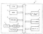
図1は、本発明の実施家板による撮像装置の一つとしてタッチパネル付きカメラを対象としたシステム構成を説明するためのブロック図であり、同図において、タッチパネル付きカメラ1は、主に、システム制御部2,撮像部3,画像処理部4,記憶メディア5,表示装置6,液晶パネル(LCD)7,タッチパネル処理部8および入力部9を備えている。
システム制御部2は、詳細を図示しないがカメラ全体の制御を実行するためのCPU、メモリおよびタイマーなどを備えて構成されており、撮像部3は、撮影に用いられるレンズおよびレンズ駆動部(モータ),CCDおよびCCD駆動回路、A/D変換器などを備えて構成されている。
【0013】
画像処理部4は、撮像部3において得られた画像情報信号を基に種々の画像処理を施すと共に撮像部3でのCCD駆動タイミング、レンズ駆動部(モータ)を制御してフォーカシングや倍率機能、露出(露光)調整さらには画像の圧縮伸長を行う機能を備えたコントローラおよびメモリで構成されている。
記憶メディア5は、画像処理部4で処理された画像情報や画像にまつわる種々情報を記憶するためのフラッシュメモリやスマートメディアなどが用いられてカメラ本体から着脱可能な構成とされている。
【0014】
表示装置6は、画像処理部4において処理された画像信号を液晶パネル7に表示するための信号処理を行うとともに、ユーザインターフェースのための種々のグラフィック画像を生成して液晶パネル7に表示するためのD/A変換器、オンスクリーンディスプレイコントローラなどを備えて構成されている。
【0015】
タッチパネル処理部8は、ペンあるいは指による押圧接触(以下、便宜上、触指と表現する)による座標位置を割り出すことができるタッチパネルを備え、その座標データの入力データをシステム制御部2に出力できる構成を備えている。
入力部9は、デジタルカメラのオンオフ制御およびシャッターなどのをはじめとする機能の操作が可能なスイッチ類を備えて構成されている。
【0016】
タッチパネル処理部8は、システム制御部2と連携してタッチパネル上での触指状態に基づき、撮影に必要な操作を設定するようになっている。操作の設定のために必要なモードは、システム制御部2において予め決められているゼスチャ動作を基準として判別されるが、触指状態とゼスチャ動作との対比による操作モードを認識する手順は次の通りである。
(1)タッチパネル上での触指状態に対応した座標データをシステム制御部2に転送し、連続して入力される座標データ上での領域が指定された場合にその指定領域を判断すると共に領域指定の際の触指状態が予め決められているゼスチャ動作に整合するかを対比判別し、領域指定およびこの指定手順とゼスチャ動作との対比を組み合わせて予め設定されている操作内容であることを認識した場合に該当する操作を決定してその操作と同じ処理を実行する。
(2)タッチパネル上での触指開始位置と触指終了位置との2点の座標が対角を示すのに基づき矩形領域を指定する対角指定モードが選択された場合、あるいは閉じた矩形領域を指定する閉じ矩形モードが選択された場合には、最終的に確定する触指位置の矩形書き出し座標が右上、右下、左上、左下のうちのいずれの角(隅)であるかを判別することにより、若しくは最終的に確定する矩形の触指位置が矩形領域のどの角(隅)であるかを判別することにより4種類の操作を識別して実行する。なお、本実施形態では対角を含む矩形として4個の角を有する形状を例示したが、本発明では、この角数に特定しないこと勿論可能である。また、始点あるいは終点に特定することなく例えば、その途中の位置座標を参照することも可能である。
図2は、ゼスチャ動作に基づき操作モードを認識する際の方式を説明するための図であり、図2(A)はゼスチャ動作における対角指定モードを示しており、同図において、始点1および終点2を触指する状態が対角指定モードである。
図2(B)は、ゼスチャ動作における閉じ矩形領域を指定(以下、閉じ指定という)する際の触指状態を示しており、開始位置(右上、右下、左上、左下)の判別あるいは最終的に確定する矩形の触指位置を判別する。
(3)システム制御部2では、閉じた領域を指定する際のゼスチャ動作の移動方向およびその順序を判別することにより方向数および順序数に応じた数の操作の識別を行う。
(4)(3)の識別に際して判別されるゼスチャ動作の移動方向は、右周りおよび左周りが相当し、移動順序は書き順に相当し、該書き順として触指開始位置(書き始め位置)と触指終了位置(書き終わり位置)および角を示す2点を加えた4点を一筆書きによる3本の線で指定する順序に相当し、移動方向を判別することにより2種類の操作を識別し、一筆書きの場合には、4点の書き順がZ形、これの逆形、N形、これの逆形のいずれかであるかに基づき4種類の操作を識別して実行する。
図2(C)および(D)は、ゼスチャ動作の移動方向(以下、便宜上、閉じ順序という)および移動順序(以下、便宜上、閉領域の書き順という)、つまり書き順による領域判別状態を示す図であり、図2(C)に示す場合には右回りでのゼスチャ動作が行われ、図2(D)では始点1から終点4に至る触指順序の一例(Z形)が示されている。
(5)ゼスチャ動作に基づき認識される操作項目および領域として、撮影時、重点的にピントおよびまたは露出を合わせる操作が対象とされ、その操作を実施する領域である場合に該当する操作を実行する。
(6)ゼスチャ動作により識別する操作項目および領域として、撮影時、重点的にホワイトバランスおよびまたはズームアップを行う捜査が対象とされ、その操作を実施する領域である場合に該当する操作を実行する。
【0017】
上述した領域指定情報およびゼスチャ動作とこれにより認識される操作内容との関連は予めシステム制御部2に登録されており、(1)〜(6)に挙げた操作認識モードに対応して操作内容が選択されて実行される。
【0018】
本実施形態は以上のような構成を用いることにより図3乃至図11に示すフローチャートに基づき撮影に必要な操作が実行される。
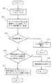
図3は(1)に挙げた処理を説明するフローチャートであり、ユーザが希望する操作を実行するための入力操作としてタッチパネルを触指することにより(ST1)、タッチパネル処理部8においてタッチパネル上での触指位置を座標データに変換してシステム制御部2に座標データを転送する(ST2)。
システム制御部2では、タッチパネル処理部8から転送された座標データに基づき領域指定の判別を行い(ST3)、領域指定の入力手順(図では入力方法と表記してある)が予め登録されているゼスチャ動作に整合するか対比される(ST4)。
ステップST3において領域指定が行われていない場合には入力待機モードを継続し(ST5)、さらにステップST4においてゼスチャ動作に整合しない場合には領域指定のみを実行する(ST6)。
【0019】
ステップST4において登録されているゼスチャ動作に対して領域指定のための入力手順が整合している場合には指定された領域とゼスチャ動作とに基づき予め割り付けられている操作を決定してその操作内容を実行する(ST7)。
【0020】
図4は(2)に挙げた処理を説明するためのフローチャートである。なお、図4以降のフローチャートにおいて、図3に示した内容と同じ処理は同符号により示してある。
図4に示す処理が実行される際には、ステップST1〜ST3までの処理は(1)に挙げた処理と同様に実行され、ステップST3において領域指定があったと判別された場合には、領域指定の入力方法(ゼスチャ)が対角指定であるかどうかが判別される(ST8)。ステップST8において対角指定である場合にはゼスチャによる領域指定の書き出しの対角(右上、右下、左上、左下)を確認していずれかの角を判別した結果に対応して割り付けられている4種類の操作をシステム制御部2において識別し(ST9)、識別された結果に対して予め割り付け(設定)されている操作を決定してその操作内容を実行する(ST10)。
【0021】
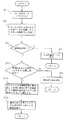
図5は(3)に挙げた処理を実行するためのフローチャートであり、同図において、領域指定があると判別した場合(ST3)には、領域指定方法が、図2(B)に示した閉じ指定であるかどうかを判別する(ST11)。閉じ指定、つまり、最終的に確定する触指位置の矩形書き出し座標が右上、右下、左上、左下のうちのいずれの角(隅)であるかを判別することにより、若しくは最終的に確定する矩形の触指位置が矩形領域のどの角(隅)であるかを判別し、その結果をシステム制御部2において識別し(ST12)、識別結果に対応する操作内容を決定して、予め割り付けられている操作を実行する(ST13)。
【0022】
図6および図7は(3)および(4)に挙げた処理を実行するためのフローチャートであり、図6においては、図2(C)に示した閉じ指定での触指位置の移動方向を判別することにより、移動方向に応じた2種類の操作を実行し(ST14,15)、図7においては、図2(D)において始点1〜終点4に至るまでの移動順序、つまり書き出しでの3本指定の方向を確認して4種類の操作をシステム制御部2において種別した上で、予め割り付けられている操作内容を決定して操作を実行する(ST16〜ST18)。
【0023】
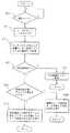
図8は(5)に挙げた処理のうちでピント設定を行う場合のフローチャートであり、撮影モードであるかどうかがカメラ本体の電源スイッチをオンオフされたかどうか、あるいは撮影モードと表示モードとの切換スイッチによる選択動作により判別し(ST19)、撮影モードである場合にはタッチパネル上での触指状態により得られる座標データをシステム制御部2に転送し(ST1,ST2)、転送された座標データに基づき領域指定の有無が判別される(ST3)。
【0024】
領域指定が行われたことが判別されると領域指定の際にゼスチャ動作が対比されたどうかが判別(図では認識と表記してある)され(ST20)、ゼスチャ動作が対比された場合には領域指定した場所を対象とするピント設定が行われると同時にゼスチャ動作の判別結果に対応する操作が決定(図では認識と表記してある)されて実行される(ST21)。ステップST20においてゼスチャ動作に対応した操作が判別されないでゼスチャ動作に基づく操作が決定(認識)されなかった場合には、領域指定された位置を対象とするピント設定のみが実行される(ST22)。
【0025】
図9は(5)に挙げた処理のうちで露出合わせ(測光)を行う場合のフローチャートであり、ステップST19並びにステップST1〜ST3およびST20の処理が実行され、ステップST20においてゼスチャ動作が対比された場合には、領域指定した場所を測光対象とする動作、つまり測光が実行されると同時にゼスチャ動作の判別結果に対応する操作が決定(図では認識と表記してある)されて実行される(ST23)。ステップST20においてゼスチャ動作が判別されないでゼスチャ動作に基づく操作が決定(認識)されなかった場合には、領域指定された場所を対象として測光動作のみが行われる(ST24)。
【0026】
図10は(6)に挙げた処理のうちでホワイトバランス調整を行う場合のフローチャートであり、ステップST20においてゼスチャ動作が対比された場合には、領域指定された場所をホワイトバランス調整対象として設定すると同時にゼスチャ動作に基づき決定(図では認識と表記してある)された操作を実行する(ST25)。ステップST20においてゼスチャ動作が判別されないでゼスチャ動作に基づく操作が決定(認識)されなかった場合には、領域指定された場所に関するホワイトバランス調整のみを行なう。(ST26)。
【0027】
図11は(6)に挙げた処理のうちでズーミングを行う場合のフローチャートであり、同図においてステップST20において領域指定の際のゼスチャ動作が対比された場合には、領域指定された場所をズーミング対象としてズーミングを行うと共に、ゼスチャ動作に基づく操作が決定(図では認識と表記してある)された操作を実行する(ST27)。ステップST20においてゼスチャ動作が認識されなかった場合には、領域指定された場所のズーミングのみを実行する(ST28)。
【0028】
以上の説明から明らかなように、本実施形態では、カメラの撮影操作であるピント合わせや露光調整あるいはホワイトバランス調整をタッチパネルでのゼスチャ動作による領域指定において行えるので、タッチパネル以外の部分でのモード選択などを要することがなく、撮影時にカメラの向きを撮影目標から外して設定し直すなどの操作を要することなく極端にいえば片手操作により撮影することができるというような利便性を得ることができる。この結果、撮影時には、ファインダあるいは液晶画面で撮影目標を視認したままで撮影を行うことができるので、操作性を向上させると共に撮影チャンスを逃すなどの不具合を解消することができる。
【0029】
【発明の効果】
請求項1および2記載の発明によれば、タッチパネル処理部においてタッチパネルでの2点の端点位置と触指軌跡を予め決められているゼスチャ動作と対比し、指定された領域から予め設定されている操作を決定する機能により領域指定と領域指定に基づく操作指定をゼスチャ動作のみで可能にすることができ、操作の利便性を向上させることが可能となる。特に、請求項2記載の発明においては、矩形領域のどの角が触指開始および終了位置であるかを判別するだけで4種類の操作を識別することができるので、一々操作の種類を指定することなくゼスチャ動作のみで操作の実行が可能となり、操作の利便性を向上させることができる。
【0031】
請求項3および4記載の発明によれば、ゼスチャ動作の移動方向およびまたはその順序を判別して方向数および順序数に対応した数の操作を識別でき、特に請求項4記載の発明では、移動方向として右周りあるいは左回りによって、また、一筆書きの書き順によってそれぞれ2種類およびまたは4種類の操作を識別できるので、タッチパネルでのゼスチャ動作のみで撮影モードや表示条件に関する操作設定が可能となり、操作の利便性を向上させることができる。
【0032】
請求項5記載の発明によれば、ゼスチャ動作による操作項目および領域に基づく操作が関連づけられているので、一々、モード選択のための操作を要することなく1回のゼスチャ動作により撮影時での操作内容を確定することができ操作の利便性を向上させることが可能となる。
【図面の簡単な説明】
【図1】 本発明の実施形態による撮像装置としてタッチパネル付きカメラを対象としたシステム構成を説明するためのブロック図である。
【図2】図1に示したシステム構成におけるタッチパネル上でのゼスチャ動作に相当する触指状態を説明するための図であり、(A)は対角指定モードを、(B)は閉じ指定モードを、(C)は閉じ書き順指定状態を、(D)閉領域の書き順状態をそれぞれ示している。
【図3】図1に示したシステム構成に用いられるシステム制御部の作用の一つを説明するためのフローチャートである。
【図4】図1に示したシステム構成に用いられるシステム制御部の作用の他の一つを説明するためのフローチャートである。
【図5】図1に示したシステム構成に用いられるシステム制御部の作用の別の一つを説明するためのフローチャートである。
【図6】図1に示したシステム構成に用いられるシステム制御部の作用のさらに別の一つを説明するためのフローチャートである。
【図7】図1に示したシステム構成に用いられるシステム制御部の作用のさらに他の一つを説明するためのフローチャートである。
【図8】図1に示したシステム構成に用いられるシステム制御部の別の作用を説明するためのフローチャートである。
【図9】図1に示したシステム構成に用いられるシステム制御部の他の作用を説明するためのフローチャートである。
【図10】図1に示したシステム構成に用いられるシステム制御部のさらに別の作用を説明するためのフローチャートである。
【図11】図1に示したシステム構成に用いられるシステム制御部のさらに他の作用を説明するためのフローチャートである。
【符号の説明】
1 タッチパネル付きカメラ
2 システム制御部
8 タッチパネル処理部[0001]
[Technical field to which the invention belongs]
The present invention relates to animaging apparatus , and more particularly, to a configuration for determining a finger state on a touch panel applied toa digital camerathat is one of imaging apparatuses and setting operation content.
[0002]
[Prior art]
Cameras that are photographing apparatuses include those using a silver salt film and digital cameras capable of recording and storing captured images electronically and magnetically without using this film.
In addition to providing a finder for visually recognizing a subject to be photographed, a digital camera often includes a liquid crystal screen on which a photographed image can be confirmed and a photographing mode can be set.
[0003]
In digital cameras that use a liquid crystal screen, instead of providing input switches for shooting mode and shooting conditions, a touch panel is provided on the surface of the liquid crystal screen to select handwritten characters on the touch panel and display content on the liquid crystal screen, such as icons. As a configuration for inputting a shooting mode and display conditions using a touch panel that has been proposed to be used as an input operation unit, a so-called graphical user interface (GUI), a shooting target displayed on a liquid crystal screen A configuration has been proposed in which an operation necessary for shooting can be selected by pressing the corresponding position on the touch panel with a finger or a pen, or by tracing the range in addition to pressing the corresponding position (for example, JP-A-11-136568).
In the above publication, exposure, zooming, and further, by performing an operation of pressing the touch panel to select an input mode of a shooting mode or display condition and an operation of pressing or tracing the touch panel to specify a shooting symmetric position. A configuration that can perform operations such as focusing is disclosed.
[0004]
[Problems to be solved by the invention]
In the configuration disclosed in the above publication, since the pressing operation is required twice as an operation procedure of the touch panel, depending on the order, the operation cannot be selected or the touch panel must be touched several times. Therefore, there is a risk of complicated operation.
[0005]
An object of the present invention is to provide a camera with a touch panel having a configuration that can ensure convenience in terms of operability, in view of the problems inan imaging apparatus such as the conventional camera with a touch panel.
[0006]
[Means for Solving the Problems]
According to the first aspect of the present invention, in the imaging device including a display unit that displays a captured image, a touch panel disposed on a surface of the display device and a tactile state operated by an operator on the touch panel are detected. A detection unit, and a control unit that discriminates two end point positions and a finger trajectory from the detection unit, and the control unitdiagonally coordinates the two points of the touch finger start position and the touch finger end position.arectangular region and Sawayubi trajectorybased on show, is characterized by performing the imaging and or reproducing operation content is preset for a predetermined in that the rectangular region in contrast with gestures operation.
[0007]
According to a second aspect of the present invention, the control unitdesignates a rectangular areabased on the coordinates of the two points of the touch finger start position and the touch finger end position,and the writing trajectory of the touch finger end is at the upper right. 4 types of operations are executed by discriminating whether the position is one of lower right, upper left, or lower left.
[0008]
According to athird aspect of the present invention, there is provided an imaging device including a display unit that displays a captured image, and detecting a touch panel disposed on a surface of the display device and a tactile state operated by an operator on the touch panel. A detection unit; and a control unit that discriminates a finger trajectory designated by three lines drawn by one stroke with four points including two points indicating an end point and a corner from the detection unit. Theclosed region specified by the positionof the pointand four types of gestures determined by discriminating whether the finger trajectory is a Z-shaped, its inverse, N-type or its inverse gesture action The imaging and / or playback operation content is executed.
[0009]
According to a fourth aspect of the present invention, in the imaging apparatus according to any one of the first tothird aspects, the control unitfocuses on focus, exposure, and white as operation items and areas to be determined by agesture operation at the time of shooting. It is characterized in thatit corresponds to an area where any one or all of the balance and zoom-up operations are performed in combination .
[0010]
According to a fifth aspect of the present invention, in the imaging apparatus according to any one of the first tothird aspects, the control unit determines the finger trajectory in comparison with a predetermined gesture operation. When it is determined that it does not correspond to the gesture operation, only the area designation is executed.
[0012]
DETAILED DESCRIPTION OF THE INVENTION
Hereinafter, embodiments of the present invention will be described with reference to the drawings.
FIG. 1 is a block diagram for explaininga system configuration fora camerawith a touch panelas one of theimaging devices using the house board of the present invention. In the figure, the camera 1 with a touch panel is mainly a system. A
Although not shown in detail, the
[0013]
The image processing unit 4 performs various image processing based on the image information signal obtained in the
The
[0014]
The
[0015]
The touch panel processing unit 8 includes a touch panel that can determine a coordinate position by pressing contact with a pen or a finger (hereinafter referred to as a touch finger for convenience), and can output input data of the coordinate data to the
The input unit 9 includes switches that can operate functions such as on / off control of a digital camera and a shutter.
[0016]
The touch panel processing unit 8 is configured to set an operation necessary for photographing based on the touch state on the touch panel in cooperation with the
(1) When coordinate data corresponding to the touched finger state on the touch panel is transferred to the
(2) When the diagonal designation mode for designating a rectangular area is selected based on the coordinates of the two points of the touching finger start position and the touching finger end position on the touch panel, or a closed rectangular area When the closed rectangle mode for specifying is selected, it is determined whether the rectangle writing coordinate of the finally determined finger position is the upper right, lower right, upper left, or lower left corner. Thus, the four types of operations are identified and executed by determining which corner (corner) of the rectangular area is the finally determined rectangular tentacle position. In the present embodiment, a shape having four corners is illustrated as a rectangle including diagonals. However, in the present invention, it is of course possible not to specify the number of corners. For example, it is possible to refer to the position coordinates in the middle without specifying the start point or the end point.
FIG. 2 is a diagram for explaining a method for recognizing the operation mode based on the gesture operation, and FIG. 2A shows a diagonal designation mode in the gesture operation. The state of touching the
FIG. 2B shows a tactile state when a closed rectangular region is designated (hereinafter referred to as “closed designation”) in the gesture operation, and the start position (upper right, lower right, upper left, lower left) is determined or finally determined. The position of the rectangular touch finger to be determined is determined.
(3) The
(4) The movement direction of the gesture motion determined in the identification in (3) corresponds to the clockwise rotation and the counterclockwise rotation, the movement order corresponds to the writing order, and the tactile finger start position (writing start position) is used as the writing order. Corresponds to the order in which four points including the touching finger end position (writing end position) and two points indicating corners are designated by three lines drawn with a single stroke, and two types of operations are identified by determining the moving direction. In the case of one-stroke writing, four types of operations are identified and executed based on whether the writing order of the four points is Z-type, its reverse form, N-type, or its reverse form.
2C and 2D show the movement direction (hereinafter referred to as the closing order for convenience) and the movement order (hereinafter referred to as the closed area writing order for convenience) of the gesture operation, that is, the region discrimination state based on the writing order. In the case shown in FIG. 2 (C), a clockwise gesture operation is performed, and in FIG. 2 (D), an example of the finger order from the start point 1 to the end point 4 (Z shape) is shown. Yes.
(5) As the operation items and areas recognized based on the gesture action, an operation corresponding to focus and / or exposure focusing at the time of shooting is a target, and an operation corresponding to the operation is executed. .
(6) As an operation item and area identified by a gesture operation, an operation corresponding to an investigation in which white balance and / or zoom-up are focused at the time of shooting is performed and the operation is performed is executed. .
[0017]
The relationship between the region designation information and the gesture operation described above and the operation content recognized thereby is registered in the
[0018]
In the present embodiment, operations necessary for photographing are executed based on the flowcharts shown in FIGS. 3 to 11 by using the above-described configuration.
FIG. 3 is a flowchart for explaining the processing described in (1). By touching the touch panel as an input operation for executing an operation desired by the user (ST1), the touch panel processing unit 8 performs the operation on the touch panel. The finger position is converted into coordinate data, and the coordinate data is transferred to the system control unit 2 (ST2).
In the
When the area designation is not performed in step ST3, the input standby mode is continued (ST5), and when not consistent with the gesture operation in step ST4, only the area designation is performed (ST6).
[0019]
If the input procedure for area designation matches the gesture action registered in step ST4, an operation assigned in advance is determined based on the designated area and the gesture action, and the contents of the operation are determined. Is executed (ST7).
[0020]
FIG. 4 is a flowchart for explaining the processing described in (2). In the flowcharts after FIG. 4, the same processes as those shown in FIG. 3 are denoted by the same reference numerals.
When the process shown in FIG. 4 is executed, the processes from step ST1 to ST3 are executed in the same way as the process given in (1). If it is determined in step ST3 that the area has been designated, the area It is determined whether the designated input method (gesture) is diagonal designation (ST8). In the case of diagonal designation in step ST8, allocation is performed corresponding to the result of confirming the diagonal (upper right, lower right, upper left, lower left) of area designation writing by gesture and discriminating one of the corners. The four types of operations are identified in the system control unit 2 (ST9), the operations assigned (set) in advance to the identified results are determined, and the contents of the operations are executed (ST10).
[0021]
FIG. 5 is a flowchart for executing the processing described in (3). In the same figure, when it is determined that there is an area designation (ST3), the area designation method is shown in FIG. It is determined whether or not it is a close designation (ST11). Closed, that is, by determining whether the rectangle writing coordinates of the finger position to be finally determined is the upper right, lower right, upper left, or lower left corner (corner), or finally determined It is determined which corner (corner) of the rectangular finger position is in the rectangular area, the result is identified in the system control unit 2 (ST12), and the operation content corresponding to the identification result is determined and assigned in advance. The operation is performed (ST13).
[0022]
FIGS. 6 and 7 are flowcharts for executing the processes listed in (3) and (4). In FIG. 6, the movement direction of the finger position in the close designation shown in FIG. By discriminating, two types of operations according to the moving direction are executed (ST14, 15). In FIG. 7, the moving order from the start point 1 to the end point 4 in FIG. After confirming the three designated directions and classifying the four types of operations in the
[0023]
FIG. 8 is a flowchart in the case where the focus setting is performed among the processes listed in (5). Whether the camera is in the shooting mode is turned on or off, or the camera mode is switched between the display mode and the display mode. It is determined by the selection operation by the switch (ST19), and when it is in the photographing mode, the coordinate data obtained by the touching state on the touch panel is transferred to the system control unit 2 (ST1, ST2), Based on this, the presence / absence of area designation is determined (ST3).
[0024]
When it is determined that the area designation has been performed, it is determined whether or not the gesture action is compared with the area designation (indicated as recognition in the figure) (ST20), and if the gesture action is compared, At the same time as the focus setting for the designated area, the operation corresponding to the determination result of the gesture operation is determined (represented as recognition in the drawing) and executed (ST21). If the operation corresponding to the gesture operation is not discriminated in step ST20 and the operation based on the gesture operation is not determined (recognized), only focus setting for the region designated position is executed (ST22).
[0025]
FIG. 9 is a flowchart in the case of performing exposure adjustment (photometry) among the processes listed in (5). The processes in step ST19 and steps ST1 to ST3 and ST20 are executed, and the gesture operation is compared in step ST20. In such a case, an operation corresponding to the result of the gesture operation is determined (recognized in the figure) and executed at the same time as the operation for setting the area designated as a photometric object, that is, photometry is executed ( ST23). If the gesture operation is not discriminated in step ST20 and the operation based on the gesture operation is not determined (recognized), only the photometric operation is performed on the area designated as the target (ST24).
[0026]
FIG. 10 is a flowchart in the case of performing white balance adjustment among the processes listed in (6). If the gesture operation is compared in step ST20, the region designated location is set as the white balance adjustment target. At the same time, the operation determined (represented as recognition in the figure) based on the gesture action is executed (ST25). If the gesture operation is not discriminated in step ST20 and the operation based on the gesture operation is not determined (recognized), only the white balance adjustment relating to the designated area is performed. (ST26).
[0027]
FIG. 11 is a flowchart when zooming is performed among the processes listed in (6). In FIG. 11, when the gesture operation at the time of area designation is compared in step ST20, zooming is performed at the area designated area. While performing zooming as an object, an operation based on a gesture motion is determined (represented as recognition in the figure) (ST27). If the gesture operation is not recognized in step ST20, only zooming at the location designated by the area is executed (ST28).
[0028]
As is clear from the above description, in this embodiment, since focus adjustment, exposure adjustment, or white balance adjustment, which are camera shooting operations, can be performed in the area designation by the gesture operation on the touch panel, mode selection in a part other than the touch panel is possible. It is possible to obtain the convenience that shooting can be performed by one-handed operation in an extreme case without requiring an operation such as removing the camera direction from the shooting target and setting it again during shooting. . As a result, at the time of shooting, shooting can be performed while the shooting target is visually recognized on the finder or the liquid crystal screen, so that it is possible to improve the operability and solve problems such as missing shooting opportunities.
[0029]
【The invention's effect】
According to the first and secondaspects of the present invention, thetwo end point positions and the finger trajectory on the touch panel in the touch panel processing unit are compared with a predetermined gesture operation and set in advance from a designated area. With the function for determining the operation, the area designation and the operation designation based on the area designation can be performed only by the gesture operation, and the convenience of the operation can be improved.In particular, in the invention described in
[0031]
According to the third and fourth aspects of the invention, the movement direction and / or order of the gesture motion can be determined to identify the number of operations corresponding to the number of directions and the number of orders. Two or four types of operation can be identified by turning clockwise or counterclockwise as the direction, and by the stroke order of one stroke, so operation settings related to the shooting mode and display conditions can be made only with gesture operation on the touch panel. The convenience of operation can be improved.
[0032]
According to the invention described in
[Brief description of the drawings]
Is a block diagram for explaining a systemconfiguration for a touch panel cameraas an imaging apparatus according to an embodiment of the present invention; FIG.
FIGS. 2A and 2B are diagrams for explaining a tactile state corresponding to a gesture operation on the touch panel in the system configuration shown in FIG. 1, wherein FIG. 2A is a diagonal designation mode, and FIG. 2B is a close designation mode; (C) shows the closed writing order designation state, and (D) shows the writing order state of the closed area.
FIG. 3 is a flowchart for explaining one of the actions of a system control unit used in the system configuration shown in FIG. 1;
4 is a flowchart for explaining another operation of the system control unit used in the system configuration shown in FIG. 1; FIG.
FIG. 5 is a flowchart for explaining another operation of the system control unit used in the system configuration shown in FIG. 1;
6 is a flowchart for explaining yet another operation of the system control unit used in the system configuration shown in FIG. 1; FIG.
7 is a flowchart for explaining yet another operation of the system control unit used in the system configuration shown in FIG. 1; FIG.
FIG. 8 is a flowchart for explaining another operation of the system control unit used in the system configuration shown in FIG. 1;
FIG. 9 is a flowchart for explaining another operation of the system control unit used in the system configuration shown in FIG. 1;
10 is a flowchart for explaining another operation of the system control unit used in the system configuration shown in FIG. 1; FIG.
FIG. 11 is a flowchart for explaining still another operation of the system control unit used in the system configuration shown in FIG. 1;
[Explanation of symbols]
1 Camera with
Claims (5)
Translated fromJapanese前記表示装置の表面に配置されているタッチパネルと、
前記タッチパネル上で操作者が操作する触指状態を検出する検出部と、
前記検出部からの2点の端点位置と触指軌跡を判別する制御部を有し、
前記制御部は触指開始位置と触指終了位置との2点の座標が対角を示すのに基づく矩形領域と触指軌跡とを、予め決められているゼスチャ動作と対比して該矩形領域に対して予め設定されている撮像およびまたは再生操作内容を実行することを特徴とする撮像装置。In an imaging apparatus including a display unit that displays a captured image,
A touch panel disposed on the surface of the display device;
A detection unit for detecting a finger state operated by an operator on the touch panel;
A control unit for discriminating two end point positions and a finger trajectory from the detection unit;
The control unitcompares the rectangular area based on the coordinates of the two points of the touching finger start position and the touching finger end position and the touching finger trajectorywith a predetermined gesture action, and thereby the rectangular area. An imaging device that executes preset imaging and / or playback operation content.
前記制御部は、触指開始位置と触指終了位置との2点の座標が対角を示すのに基づき矩形領域を指定し、触指終了の書き出し軌跡が右上、右下、左上、左下のうちのいずれかであるかを判別することにより4種類の操作を実行することを特徴とする撮像装置。The imaging device according to claim 1,
The control unitdesignates a rectangular areabased on the coordinates of the two points of the tentacle start position and the tentacle end position,and the writing end locus of the tentacle ends is upper right, lower right, upper left, lower left. An image pickup apparatus that performs four types of operations by determining which of them is one of them.
前記表示装置の表面に配置されているタッチパネルと、
前記タッチパネル上で操作者が操作する触指状態を検出する検出部と、
前記検出部からの端点と角を示す2点を加えた4点を一筆書きによる3本の線で指定される触指軌跡を判別する制御部を有し、
前記制御部は4点の位置で指定される閉じた領域と、触指軌跡がZ形、これの逆形、N形、これの逆形のいずれのゼスチャ動作であるかを判別することにより決定される4種類の撮像およびまたは再生操作内容を実行することを特徴とする撮像装置。In an imaging apparatus including a display unit that displays a captured image,
A touch panel disposed on the surface of the display device;
A detection unit for detecting a finger state operated by an operator on the touch panel;
A control unit for determining a finger trajectory designated by three lines drawn by one stroke with four points including two points indicating an end point and a corner from the detection unit;
The control unit determines theclosed region specified by the positionof four pointsand whether the finger trajectory is a Z-shaped, its inverse, N-type, or its inverse gesture action. An imaging apparatus that executesfour types of imaging and / or playback operation contents.
前記制御部は、ゼスチャ動作により判断する操作項目および領域として、撮影時、重点的にピント、露出、ホワイトバランス、ズームアップ操作のいずれか或いは全部の項目を組み合せて実施する領域に相当させていることを特徴とする撮像装置。The imaging device according to any one of claims 1 to3 ,
The control unit corresponds to an operation item and area to be determined by gesture operation, corresponding to an area to be executed by combining any or all of focus, exposure, white balance, and zoom-up operations at the time of shooting. An imaging apparatus characterized by that.
前記制御部が、触指軌跡を予め決められているゼスチャ動作と対比して、該予め決められているゼスチャ動作に該当しないと判断したときは、領域指定のみを実行することを特徴とする撮像装置。The imaging device according to any one of claims 1 to3 ,
When the control unit determines that the finger trajectory does not correspond to the predetermined gesture operation by comparing the trajectory with the predetermined gesture operation, only the area designation is executed. apparatus.
Priority Applications (1)
| Application Number | Priority Date | Filing Date | Title |
|---|---|---|---|
| JP2002122318AJP4107568B2 (en) | 2002-04-24 | 2002-04-24 | Imaging device |
Applications Claiming Priority (1)
| Application Number | Priority Date | Filing Date | Title |
|---|---|---|---|
| JP2002122318AJP4107568B2 (en) | 2002-04-24 | 2002-04-24 | Imaging device |
Publications (3)
| Publication Number | Publication Date |
|---|---|
| JP2003319244A JP2003319244A (en) | 2003-11-07 |
| JP2003319244A5 JP2003319244A5 (en) | 2006-03-16 |
| JP4107568B2true JP4107568B2 (en) | 2008-06-25 |
Family
ID=29537961
Family Applications (1)
| Application Number | Title | Priority Date | Filing Date |
|---|---|---|---|
| JP2002122318AExpired - LifetimeJP4107568B2 (en) | 2002-04-24 | 2002-04-24 | Imaging device |
Country Status (1)
| Country | Link |
|---|---|
| JP (1) | JP4107568B2 (en) |
Families Citing this family (9)
| Publication number | Priority date | Publication date | Assignee | Title |
|---|---|---|---|---|
| JP4510713B2 (en)* | 2005-07-21 | 2010-07-28 | 富士フイルム株式会社 | Digital camera |
| JP2007241410A (en)* | 2006-03-06 | 2007-09-20 | Pioneer Electronic Corp | Display device and display control method |
| US10021291B2 (en) | 2006-11-16 | 2018-07-10 | Samsung Electronics Co., Ltd | Portable device enabling a user to manually adjust locations of focusing and photometry and method for taking images |
| JP4513903B2 (en)* | 2008-06-25 | 2010-07-28 | ソニー株式会社 | Image processing apparatus and image processing method |
| JP5257841B2 (en)* | 2008-10-21 | 2013-08-07 | 日本電気株式会社 | Command input system, method and program thereof |
| US8423916B2 (en) | 2008-11-20 | 2013-04-16 | Canon Kabushiki Kaisha | Information processing apparatus, processing method thereof, and computer-readable storage medium |
| JP5202425B2 (en)* | 2009-04-27 | 2013-06-05 | 三菱電機株式会社 | Video surveillance system |
| JP2011040896A (en)* | 2009-08-07 | 2011-02-24 | Canon Inc | Image capturing apparatus and method of controlling the same |
| WO2015068709A1 (en)* | 2013-11-08 | 2015-05-14 | 株式会社村田製作所 | Display device and program |
- 2002
- 2002-04-24JPJP2002122318Apatent/JP4107568B2/ennot_activeExpired - Lifetime
Also Published As
| Publication number | Publication date |
|---|---|
| JP2003319244A (en) | 2003-11-07 |
Similar Documents
| Publication | Publication Date | Title |
|---|---|---|
| TWI461058B (en) | Providing area zoom functionality for a camera | |
| RU2649773C2 (en) | Controlling camera with face detection | |
| RU2514099C2 (en) | Digital image processing device and touch-based image scaling method | |
| US8654243B2 (en) | Image pickup apparatus and control method thereof | |
| US20190138110A1 (en) | Method of controlling an operation of a camera apparatus and a camera apparatus | |
| JP4127982B2 (en) | Portable electronic devices | |
| US7355620B2 (en) | Digital still camera and user instruction input method | |
| US9699389B2 (en) | Image displaying apparatus and image displaying method | |
| JP4852652B2 (en) | Electronic zoom device, electronic zoom method, and program | |
| JP2006087139A (en) | User interface system for camera control | |
| WO2017113668A1 (en) | Method and device for controlling terminal according to eye movement | |
| US20120113056A1 (en) | Input device, input method, and computer readable storage device | |
| US20110063491A1 (en) | Digital photographing apparatus and method of controlling the same | |
| EP2517092A1 (en) | Variable rate browsing of an image collection | |
| US20180324351A1 (en) | Control device, control method, and program | |
| US11496670B2 (en) | Electronic device with display screen capable of reliable detection of a user selected displayed eye region in a scene to be captured, and region selection method | |
| CN106973222A (en) | The control method and mobile terminal of a kind of Digital Zoom | |
| JP4107568B2 (en) | Imaging device | |
| JP7049179B2 (en) | Imaging control device and its control method, program and storage medium | |
| JP2011211757A (en) | Electronic zoom apparatus, electronic zoom method, and program | |
| JP6120541B2 (en) | Display control apparatus and control method thereof | |
| JP3744995B2 (en) | Imaging method and apparatus | |
| JP2020161869A (en) | Electronic apparatus, control method, and program | |
| JP2006099504A (en) | Automatic penlight control system for electronic pen with penlight, and penlight control method | |
| JP2021118400A (en) | Electronic devices, imaging devices, electronic device control methods, programs, and storage media |
Legal Events
| Date | Code | Title | Description |
|---|---|---|---|
| A621 | Written request for application examination | Free format text:JAPANESE INTERMEDIATE CODE: A621 Effective date:20041206 | |
| A521 | Request for written amendment filed | Free format text:JAPANESE INTERMEDIATE CODE: A523 Effective date:20060131 | |
| A977 | Report on retrieval | Free format text:JAPANESE INTERMEDIATE CODE: A971007 Effective date:20061012 | |
| A131 | Notification of reasons for refusal | Free format text:JAPANESE INTERMEDIATE CODE: A131 Effective date:20061017 | |
| A521 | Request for written amendment filed | Free format text:JAPANESE INTERMEDIATE CODE: A523 Effective date:20061218 | |
| A131 | Notification of reasons for refusal | Free format text:JAPANESE INTERMEDIATE CODE: A131 Effective date:20070515 | |
| A521 | Request for written amendment filed | Free format text:JAPANESE INTERMEDIATE CODE: A523 Effective date:20070717 | |
| A02 | Decision of refusal | Free format text:JAPANESE INTERMEDIATE CODE: A02 Effective date:20071113 | |
| A521 | Request for written amendment filed | Free format text:JAPANESE INTERMEDIATE CODE: A523 Effective date:20071213 | |
| A911 | Transfer to examiner for re-examination before appeal (zenchi) | Free format text:JAPANESE INTERMEDIATE CODE: A911 Effective date:20080125 | |
| TRDD | Decision of grant or rejection written | ||
| A01 | Written decision to grant a patent or to grant a registration (utility model) | Free format text:JAPANESE INTERMEDIATE CODE: A01 Effective date:20080325 | |
| A61 | First payment of annual fees (during grant procedure) | Free format text:JAPANESE INTERMEDIATE CODE: A61 Effective date:20080328 | |
| FPAY | Renewal fee payment (event date is renewal date of database) | Free format text:PAYMENT UNTIL: 20110411 Year of fee payment:3 | |
| R150 | Certificate of patent or registration of utility model | Ref document number:4107568 Country of ref document:JP Free format text:JAPANESE INTERMEDIATE CODE: R150 Free format text:JAPANESE INTERMEDIATE CODE: R150 | |
| FPAY | Renewal fee payment (event date is renewal date of database) | Free format text:PAYMENT UNTIL: 20120411 Year of fee payment:4 | |
| FPAY | Renewal fee payment (event date is renewal date of database) | Free format text:PAYMENT UNTIL: 20130411 Year of fee payment:5 | |
| FPAY | Renewal fee payment (event date is renewal date of database) | Free format text:PAYMENT UNTIL: 20140411 Year of fee payment:6 | |
| EXPY | Cancellation because of completion of term |