JP4106019B2 - Method and apparatus for intermittently occluding a coronary sinus - Google Patents
Method and apparatus for intermittently occluding a coronary sinusDownload PDFInfo
- Publication number
- JP4106019B2 JP4106019B2JP2003513622AJP2003513622AJP4106019B2JP 4106019 B2JP4106019 B2JP 4106019B2JP 2003513622 AJP2003513622 AJP 2003513622AJP 2003513622 AJP2003513622 AJP 2003513622AJP 4106019 B2JP4106019 B2JP 4106019B2
- Authority
- JP
- Japan
- Prior art keywords
- pressure
- value
- occlusion
- coronary sinus
- perfusate
- Prior art date
- Legal status (The legal status is an assumption and is not a legal conclusion. Google has not performed a legal analysis and makes no representation as to the accuracy of the status listed.)
- Expired - Fee Related
Links
- 210000003748coronary sinusAnatomy0.000titleclaimsdescription39
- 238000000034methodMethods0.000titledescription10
- 239000012530fluidSubstances0.000claimsdescription27
- 230000010412perfusionEffects0.000claimsdescription18
- 210000003462veinAnatomy0.000claimsdescription16
- 238000009530blood pressure measurementMethods0.000claimsdescription9
- 210000004204blood vesselAnatomy0.000claimsdescription5
- 238000011156evaluationMethods0.000claimsdescription5
- 230000004872arterial blood pressureEffects0.000claimsdescription3
- 230000000302ischemic effectEffects0.000description18
- 239000008280bloodSubstances0.000description14
- 210000004369bloodAnatomy0.000description14
- 210000004351coronary vesselAnatomy0.000description10
- 230000007704transitionEffects0.000description10
- 210000001519tissueAnatomy0.000description9
- 230000006870functionEffects0.000description8
- 210000004165myocardiumAnatomy0.000description7
- 235000015097nutrientsNutrition0.000description7
- 230000035488systolic blood pressureEffects0.000description7
- 230000036962time dependentEffects0.000description6
- 210000001367arteryAnatomy0.000description5
- 210000005003heart tissueAnatomy0.000description5
- 230000010247heart contractionEffects0.000description4
- 238000002347injectionMethods0.000description4
- 239000007924injectionSubstances0.000description4
- 206010011086Coronary artery occlusionDiseases0.000description3
- QVGXLLKOCUKJST-UHFFFAOYSA-Natomic oxygenChemical compound[O]QVGXLLKOCUKJST-UHFFFAOYSA-N0.000description3
- 230000035487diastolic blood pressureEffects0.000description3
- 238000001802infusionMethods0.000description3
- 229940113601irrigation solutionDrugs0.000description3
- 239000001301oxygenSubstances0.000description3
- 229910052760oxygenInorganic materials0.000description3
- 208000001778Coronary OcclusionDiseases0.000description2
- 230000004087circulationEffects0.000description2
- 230000006735deficitEffects0.000description2
- 238000013152interventional procedureMethods0.000description2
- 230000007774longtermEffects0.000description2
- 230000002503metabolic effectEffects0.000description2
- 230000002107myocardial effectEffects0.000description2
- 239000002831pharmacologic agentSubstances0.000description2
- 230000002966stenotic effectEffects0.000description2
- 239000000126substanceSubstances0.000description2
- 206010003210ArteriosclerosisDiseases0.000description1
- 239000013543active substanceSubstances0.000description1
- 230000004075alterationEffects0.000description1
- 238000002399angioplastyMethods0.000description1
- 239000003146anticoagulant agentSubstances0.000description1
- 229940127219anticoagulant drugDrugs0.000description1
- 230000008321arterial blood flowEffects0.000description1
- 208000011775arteriosclerosis diseaseDiseases0.000description1
- 239000002876beta blockerSubstances0.000description1
- 229940097320beta blocking agentDrugs0.000description1
- 230000017531blood circulationEffects0.000description1
- 230000000747cardiac effectEffects0.000description1
- 230000008602contractionEffects0.000description1
- 239000002872contrast mediaSubstances0.000description1
- 238000007887coronary angioplastyMethods0.000description1
- 239000007857degradation productSubstances0.000description1
- 238000003745diagnosisMethods0.000description1
- 238000010586diagramMethods0.000description1
- 230000010339dilationEffects0.000description1
- 238000007599dischargingMethods0.000description1
- 230000000694effectsEffects0.000description1
- 230000005284excitationEffects0.000description1
- 239000003527fibrinolytic agentSubstances0.000description1
- 210000002837heart atriumAnatomy0.000description1
- 230000002262irrigationEffects0.000description1
- 238000003973irrigationMethods0.000description1
- 238000005259measurementMethods0.000description1
- 238000012544monitoring processMethods0.000description1
- 230000010016myocardial functionEffects0.000description1
- 208000031225myocardial ischemiaDiseases0.000description1
- 238000005457optimizationMethods0.000description1
- 230000000144pharmacologic effectEffects0.000description1
- 238000012545processingMethods0.000description1
- 239000000047productSubstances0.000description1
- 230000009897systematic effectEffects0.000description1
- 229960000103thrombolytic agentDrugs0.000description1
- 230000002861ventricularEffects0.000description1
- 239000002699waste materialSubstances0.000description1
Images


Classifications
- A—HUMAN NECESSITIES
- A61—MEDICAL OR VETERINARY SCIENCE; HYGIENE
- A61M—DEVICES FOR INTRODUCING MEDIA INTO, OR ONTO, THE BODY; DEVICES FOR TRANSDUCING BODY MEDIA OR FOR TAKING MEDIA FROM THE BODY; DEVICES FOR PRODUCING OR ENDING SLEEP OR STUPOR
- A61M1/00—Suction or pumping devices for medical purposes; Devices for carrying-off, for treatment of, or for carrying-over, body-liquids; Drainage systems
- A61M1/36—Other treatment of blood in a by-pass of the natural circulatory system, e.g. temperature adaptation, irradiation ; Extra-corporeal blood circuits
- A61M1/3613—Reperfusion, e.g. of the coronary vessels, e.g. retroperfusion
- A—HUMAN NECESSITIES
- A61—MEDICAL OR VETERINARY SCIENCE; HYGIENE
- A61B—DIAGNOSIS; SURGERY; IDENTIFICATION
- A61B17/00—Surgical instruments, devices or methods
- A61B17/12—Surgical instruments, devices or methods for ligaturing or otherwise compressing tubular parts of the body, e.g. blood vessels or umbilical cord
- A61B17/12022—Occluding by internal devices, e.g. balloons or releasable wires
- A61B17/12027—Type of occlusion
- A61B17/1204—Type of occlusion temporary occlusion
- A—HUMAN NECESSITIES
- A61—MEDICAL OR VETERINARY SCIENCE; HYGIENE
- A61B—DIAGNOSIS; SURGERY; IDENTIFICATION
- A61B17/00—Surgical instruments, devices or methods
- A61B17/12—Surgical instruments, devices or methods for ligaturing or otherwise compressing tubular parts of the body, e.g. blood vessels or umbilical cord
- A61B17/12022—Occluding by internal devices, e.g. balloons or releasable wires
- A61B17/12099—Occluding by internal devices, e.g. balloons or releasable wires characterised by the location of the occluder
- A61B17/12109—Occluding by internal devices, e.g. balloons or releasable wires characterised by the location of the occluder in a blood vessel
- A—HUMAN NECESSITIES
- A61—MEDICAL OR VETERINARY SCIENCE; HYGIENE
- A61B—DIAGNOSIS; SURGERY; IDENTIFICATION
- A61B17/00—Surgical instruments, devices or methods
- A61B17/12—Surgical instruments, devices or methods for ligaturing or otherwise compressing tubular parts of the body, e.g. blood vessels or umbilical cord
- A61B17/12022—Occluding by internal devices, e.g. balloons or releasable wires
- A61B17/12131—Occluding by internal devices, e.g. balloons or releasable wires characterised by the type of occluding device
- A61B17/12136—Balloons
- A—HUMAN NECESSITIES
- A61—MEDICAL OR VETERINARY SCIENCE; HYGIENE
- A61M—DEVICES FOR INTRODUCING MEDIA INTO, OR ONTO, THE BODY; DEVICES FOR TRANSDUCING BODY MEDIA OR FOR TAKING MEDIA FROM THE BODY; DEVICES FOR PRODUCING OR ENDING SLEEP OR STUPOR
- A61M60/00—Blood pumps; Devices for mechanical circulatory actuation; Balloon pumps for circulatory assistance
- A61M60/10—Location thereof with respect to the patient's body
- A61M60/122—Implantable pumps or pumping devices, i.e. the blood being pumped inside the patient's body
- A61M60/126—Implantable pumps or pumping devices, i.e. the blood being pumped inside the patient's body implantable via, into, inside, in line, branching on, or around a blood vessel
- A61M60/135—Implantable pumps or pumping devices, i.e. the blood being pumped inside the patient's body implantable via, into, inside, in line, branching on, or around a blood vessel inside a blood vessel, e.g. using grafting
- A61M60/143—Implantable pumps or pumping devices, i.e. the blood being pumped inside the patient's body implantable via, into, inside, in line, branching on, or around a blood vessel inside a blood vessel, e.g. using grafting inside the coronary sinus, e.g. for pressure-controlled intermittent coronary sinus occlusion
- A—HUMAN NECESSITIES
- A61—MEDICAL OR VETERINARY SCIENCE; HYGIENE
- A61M—DEVICES FOR INTRODUCING MEDIA INTO, OR ONTO, THE BODY; DEVICES FOR TRANSDUCING BODY MEDIA OR FOR TAKING MEDIA FROM THE BODY; DEVICES FOR PRODUCING OR ENDING SLEEP OR STUPOR
- A61M60/00—Blood pumps; Devices for mechanical circulatory actuation; Balloon pumps for circulatory assistance
- A61M60/20—Type thereof
- A61M60/295—Balloon pumps for circulatory assistance
- A—HUMAN NECESSITIES
- A61—MEDICAL OR VETERINARY SCIENCE; HYGIENE
- A61M—DEVICES FOR INTRODUCING MEDIA INTO, OR ONTO, THE BODY; DEVICES FOR TRANSDUCING BODY MEDIA OR FOR TAKING MEDIA FROM THE BODY; DEVICES FOR PRODUCING OR ENDING SLEEP OR STUPOR
- A61M60/00—Blood pumps; Devices for mechanical circulatory actuation; Balloon pumps for circulatory assistance
- A61M60/30—Medical purposes thereof other than the enhancement of the cardiac output
- A61M60/31—Medical purposes thereof other than the enhancement of the cardiac output for enhancement of in vivo organ perfusion, e.g. retroperfusion
- A61M60/32—Medical purposes thereof other than the enhancement of the cardiac output for enhancement of in vivo organ perfusion, e.g. retroperfusion of heart muscle tissues, e.g. using coronary sinus occlusion
- A—HUMAN NECESSITIES
- A61—MEDICAL OR VETERINARY SCIENCE; HYGIENE
- A61M—DEVICES FOR INTRODUCING MEDIA INTO, OR ONTO, THE BODY; DEVICES FOR TRANSDUCING BODY MEDIA OR FOR TAKING MEDIA FROM THE BODY; DEVICES FOR PRODUCING OR ENDING SLEEP OR STUPOR
- A61M60/00—Blood pumps; Devices for mechanical circulatory actuation; Balloon pumps for circulatory assistance
- A61M60/50—Details relating to control
- A61M60/508—Electronic control means, e.g. for feedback regulation
- A61M60/515—Regulation using real-time patient data
- A61M60/531—Regulation using real-time patient data using blood pressure data, e.g. from blood pressure sensors
- A—HUMAN NECESSITIES
- A61—MEDICAL OR VETERINARY SCIENCE; HYGIENE
- A61B—DIAGNOSIS; SURGERY; IDENTIFICATION
- A61B17/00—Surgical instruments, devices or methods
- A61B2017/00017—Electrical control of surgical instruments
- A61B2017/00022—Sensing or detecting at the treatment site
- A—HUMAN NECESSITIES
- A61—MEDICAL OR VETERINARY SCIENCE; HYGIENE
- A61B—DIAGNOSIS; SURGERY; IDENTIFICATION
- A61B17/00—Surgical instruments, devices or methods
- A61B2017/00681—Aspects not otherwise provided for
- A61B2017/00694—Aspects not otherwise provided for with means correcting for movement of or for synchronisation with the body
- A61B2017/00703—Aspects not otherwise provided for with means correcting for movement of or for synchronisation with the body correcting for movement of heart, e.g. ECG-triggered
- A—HUMAN NECESSITIES
- A61—MEDICAL OR VETERINARY SCIENCE; HYGIENE
- A61M—DEVICES FOR INTRODUCING MEDIA INTO, OR ONTO, THE BODY; DEVICES FOR TRANSDUCING BODY MEDIA OR FOR TAKING MEDIA FROM THE BODY; DEVICES FOR PRODUCING OR ENDING SLEEP OR STUPOR
- A61M25/00—Catheters; Hollow probes
- A61M2025/0001—Catheters; Hollow probes for pressure measurement
- A61M2025/0003—Catheters; Hollow probes for pressure measurement having an additional lumen transmitting fluid pressure to the outside for measurement
- A—HUMAN NECESSITIES
- A61—MEDICAL OR VETERINARY SCIENCE; HYGIENE
- A61M—DEVICES FOR INTRODUCING MEDIA INTO, OR ONTO, THE BODY; DEVICES FOR TRANSDUCING BODY MEDIA OR FOR TAKING MEDIA FROM THE BODY; DEVICES FOR PRODUCING OR ENDING SLEEP OR STUPOR
- A61M25/00—Catheters; Hollow probes
- A61M25/0021—Catheters; Hollow probes characterised by the form of the tubing
- A61M25/0023—Catheters; Hollow probes characterised by the form of the tubing by the form of the lumen, e.g. cross-section, variable diameter
- A61M25/0026—Multi-lumen catheters with stationary elements
- A61M2025/0036—Multi-lumen catheters with stationary elements with more than four lumina
- A—HUMAN NECESSITIES
- A61—MEDICAL OR VETERINARY SCIENCE; HYGIENE
- A61M—DEVICES FOR INTRODUCING MEDIA INTO, OR ONTO, THE BODY; DEVICES FOR TRANSDUCING BODY MEDIA OR FOR TAKING MEDIA FROM THE BODY; DEVICES FOR PRODUCING OR ENDING SLEEP OR STUPOR
- A61M25/00—Catheters; Hollow probes
- A61M25/10—Balloon catheters
- A61M25/1011—Multiple balloon catheters
- A61M2025/1015—Multiple balloon catheters having two or more independently movable balloons where the distance between the balloons can be adjusted, e.g. two balloon catheters concentric to each other forming an adjustable multiple balloon catheter system
- A—HUMAN NECESSITIES
- A61—MEDICAL OR VETERINARY SCIENCE; HYGIENE
- A61M—DEVICES FOR INTRODUCING MEDIA INTO, OR ONTO, THE BODY; DEVICES FOR TRANSDUCING BODY MEDIA OR FOR TAKING MEDIA FROM THE BODY; DEVICES FOR PRODUCING OR ENDING SLEEP OR STUPOR
- A61M25/00—Catheters; Hollow probes
- A61M25/10—Balloon catheters
- A61M2025/1043—Balloon catheters with special features or adapted for special applications
- A61M2025/1052—Balloon catheters with special features or adapted for special applications for temporarily occluding a vessel for isolating a sector
- A—HUMAN NECESSITIES
- A61—MEDICAL OR VETERINARY SCIENCE; HYGIENE
- A61M—DEVICES FOR INTRODUCING MEDIA INTO, OR ONTO, THE BODY; DEVICES FOR TRANSDUCING BODY MEDIA OR FOR TAKING MEDIA FROM THE BODY; DEVICES FOR PRODUCING OR ENDING SLEEP OR STUPOR
- A61M2205/00—General characteristics of the apparatus
- A61M2205/33—Controlling, regulating or measuring
- A61M2205/3331—Pressure; Flow
- A61M2205/3344—Measuring or controlling pressure at the body treatment site
- A—HUMAN NECESSITIES
- A61—MEDICAL OR VETERINARY SCIENCE; HYGIENE
- A61M—DEVICES FOR INTRODUCING MEDIA INTO, OR ONTO, THE BODY; DEVICES FOR TRANSDUCING BODY MEDIA OR FOR TAKING MEDIA FROM THE BODY; DEVICES FOR PRODUCING OR ENDING SLEEP OR STUPOR
- A61M2205/00—General characteristics of the apparatus
- A61M2205/33—Controlling, regulating or measuring
- A61M2205/3331—Pressure; Flow
- A61M2205/3348—Pressure measurement using a water column
- A—HUMAN NECESSITIES
- A61—MEDICAL OR VETERINARY SCIENCE; HYGIENE
- A61M—DEVICES FOR INTRODUCING MEDIA INTO, OR ONTO, THE BODY; DEVICES FOR TRANSDUCING BODY MEDIA OR FOR TAKING MEDIA FROM THE BODY; DEVICES FOR PRODUCING OR ENDING SLEEP OR STUPOR
- A61M2205/00—General characteristics of the apparatus
- A61M2205/33—Controlling, regulating or measuring
- A61M2205/3331—Pressure; Flow
- A61M2205/3355—Controlling downstream pump pressure
- A—HUMAN NECESSITIES
- A61—MEDICAL OR VETERINARY SCIENCE; HYGIENE
- A61M—DEVICES FOR INTRODUCING MEDIA INTO, OR ONTO, THE BODY; DEVICES FOR TRANSDUCING BODY MEDIA OR FOR TAKING MEDIA FROM THE BODY; DEVICES FOR PRODUCING OR ENDING SLEEP OR STUPOR
- A61M2205/00—General characteristics of the apparatus
- A61M2205/50—General characteristics of the apparatus with microprocessors or computers
- A61M2205/52—General characteristics of the apparatus with microprocessors or computers with memories providing a history of measured variating parameters of apparatus or patient
- A—HUMAN NECESSITIES
- A61—MEDICAL OR VETERINARY SCIENCE; HYGIENE
- A61M—DEVICES FOR INTRODUCING MEDIA INTO, OR ONTO, THE BODY; DEVICES FOR TRANSDUCING BODY MEDIA OR FOR TAKING MEDIA FROM THE BODY; DEVICES FOR PRODUCING OR ENDING SLEEP OR STUPOR
- A61M25/00—Catheters; Hollow probes
- A61M25/0021—Catheters; Hollow probes characterised by the form of the tubing
- A61M25/0023—Catheters; Hollow probes characterised by the form of the tubing by the form of the lumen, e.g. cross-section, variable diameter
- A61M25/0026—Multi-lumen catheters with stationary elements
- A61M25/0032—Multi-lumen catheters with stationary elements characterized by at least one unconventionally shaped lumen, e.g. polygons, ellipsoids, wedges or shapes comprising concave and convex parts
- A—HUMAN NECESSITIES
- A61—MEDICAL OR VETERINARY SCIENCE; HYGIENE
- A61M—DEVICES FOR INTRODUCING MEDIA INTO, OR ONTO, THE BODY; DEVICES FOR TRANSDUCING BODY MEDIA OR FOR TAKING MEDIA FROM THE BODY; DEVICES FOR PRODUCING OR ENDING SLEEP OR STUPOR
- A61M60/00—Blood pumps; Devices for mechanical circulatory actuation; Balloon pumps for circulatory assistance
- A61M60/20—Type thereof
- A61M60/247—Positive displacement blood pumps
- A61M60/253—Positive displacement blood pumps including a displacement member directly acting on the blood
- A61M60/268—Positive displacement blood pumps including a displacement member directly acting on the blood the displacement member being flexible, e.g. membranes, diaphragms or bladders
- A61M60/274—Positive displacement blood pumps including a displacement member directly acting on the blood the displacement member being flexible, e.g. membranes, diaphragms or bladders the inlet and outlet being the same, e.g. para-aortic counter-pulsation blood pumps
- A—HUMAN NECESSITIES
- A61—MEDICAL OR VETERINARY SCIENCE; HYGIENE
- A61M—DEVICES FOR INTRODUCING MEDIA INTO, OR ONTO, THE BODY; DEVICES FOR TRANSDUCING BODY MEDIA OR FOR TAKING MEDIA FROM THE BODY; DEVICES FOR PRODUCING OR ENDING SLEEP OR STUPOR
- A61M60/00—Blood pumps; Devices for mechanical circulatory actuation; Balloon pumps for circulatory assistance
- A61M60/80—Constructional details other than related to driving
- A61M60/802—Constructional details other than related to driving of non-positive displacement blood pumps
- A61M60/833—Occluders for preventing backflow
Landscapes
- Health & Medical Sciences (AREA)
- Heart & Thoracic Surgery (AREA)
- Engineering & Computer Science (AREA)
- Life Sciences & Earth Sciences (AREA)
- Biomedical Technology (AREA)
- Cardiology (AREA)
- General Health & Medical Sciences (AREA)
- Animal Behavior & Ethology (AREA)
- Public Health (AREA)
- Veterinary Medicine (AREA)
- Vascular Medicine (AREA)
- Anesthesiology (AREA)
- Hematology (AREA)
- Mechanical Engineering (AREA)
- Surgery (AREA)
- Medical Informatics (AREA)
- Reproductive Health (AREA)
- Nuclear Medicine, Radiotherapy & Molecular Imaging (AREA)
- Molecular Biology (AREA)
- Transplantation (AREA)
- Physics & Mathematics (AREA)
- Optics & Photonics (AREA)
- External Artificial Organs (AREA)
- Measuring Pulse, Heart Rate, Blood Pressure Or Blood Flow (AREA)
Description
Translated fromJapanese本発明は、冠状静脈洞が閉塞装置によって閉塞され、その閉塞した冠状静脈洞内の流体圧力が連続的に測定され、また、冠状静脈洞の閉塞が測定した圧力値から求められた少なくとも1つのパラメータの関数として解放されるようにした、冠状静脈洞を間欠的に閉塞する方法及び冠状静脈洞を間欠的に閉塞する装置に関する。 According to the present invention, the coronary sinus is occluded by the occlusion device, the fluid pressure in the occluded coronary sinus is continuously measured, and at least one of the coronary sinus occlusion determined from the measured pressure value. The present invention relates to a method for intermittently occluding a coronary sinus and a device for intermittently occluding the coronary sinus that are released as a function of parameters.
心筋に供給する動脈血液は、該心筋に栄養物を供給すべく健常な心臓組織を通ることができるが、虚血性組織に達することは困難である。その結果、虚血性組織に栄養物を供給し且つ、代謝分解生成物を虚血性組織から排出することは妨げられる。この意味において、既に、逆方向灌流によって虚血性組織に血液を供給することが提案されている。冠状静脈内での血液の逆方向注入は、心臓介入法を行う時、短期間、冠状動脈が閉塞する間、特に、心筋の保護の点にて1つの重要な役割を果たす。この型式の1つの典型的な介入法は、例えば、動脈硬化症によって狭窄となった冠状動脈をバルーンで拡張する方法である。経皮経管冠動脈形成術(PTCA)としても知られるこの方法において、バルーンカテーテルをX線監視の下にて冠状動脈の狭窄領域内に導入し、動脈硬化症の斑をカテーテルの端部に取り付けられたバルーンを拡張させることによって圧縮する。バルーンが拡張する間、動脈の下流にて組織に対し酸素を含む血液の供給は行われず、既に、拡張が30秒以上続いたとき、心筋の虚血性領域内にて機能的改変が観察される。また、例えば、動脈切除法(atherectomies)、冠状血管の内部補綴法(endoprostheses)及びレーザ照射のような、冠状血管の血管形成のためのその他の介入法にて心筋の虚血の保護に関する同様の問題点に直面している。 Arterial blood supplying the myocardium can pass through healthy heart tissue to supply the heart muscle with nutrients, but it is difficult to reach ischemic tissue. As a result, supplying nutrients to the ischemic tissue and discharging metabolic degradation products from the ischemic tissue is prevented. In this sense, it has already been proposed to supply blood to ischemic tissue by reverse perfusion. Reverse injection of blood in the coronary vein plays an important role when performing cardiac interventions, during a short period of time when the coronary artery is occluded, especially in terms of myocardial protection. One typical intervention of this type is, for example, a balloon expansion of a coronary artery that has become stenotic due to arteriosclerosis. In this method, also known as percutaneous transluminal coronary angioplasty (PTCA), a balloon catheter is introduced into the stenotic area of the coronary artery under X-ray monitoring and an arteriosclerotic plaque is attached to the end of the catheter. Compress the balloon by expanding the balloon. While the balloon is inflated, there is no oxygen supply to the tissue downstream of the artery, and a functional alteration is already observed in the ischemic region of the myocardium when the dilation has continued for more than 30 seconds. . Also, similar to the protection of myocardial ischemia in other interventions for coronary vessel angioplasty, such as arteriotomy, coronary endoprosthesis, and laser irradiation. We are facing problems.
短期間の虚血の保護に関して、心筋におけるそれぞれの虚血性領域の静脈内に動脈血液又はその他の栄養液体を逆方向注入することが、一時期行われていた。これらを行うとき、血液は、それぞれ静脈を通じて虚血性領域の栄養供給毛管内に圧送され、これにより、その領域内の心筋に酸素及び物質を供給する。圧力制御された間欠的な冠状血管の閉塞を行うための逆方向注入装置は、例えば、米国特許第4,934,996号から既知である。該装置は、例えば、拡張可能なバルーンカテーテルのような、洞を閉塞する手段と、冠状静脈洞内の流体圧力を測定する圧力測定手段と、閉塞を励起させ又は解放する励起信号を発生させる制御手段とを備えている。制御手段は、各心拍時における最高圧力が冠状静脈洞にて測定され、連続的な心拍の圧力最高値のプラトー値が計算によって推定され且つ、圧力最高値のプラトー値に基づいて冠状静脈洞の閉塞が解放されるような仕方にて設計されている。 For short-term ischemic protection, it has been a period of time to reversely infuse arterial blood or other nutrient fluid into the veins of each ischemic region in the myocardium. In doing so, blood is pumped through each vein into the nutrient supply capillary of the ischemic region, thereby supplying oxygen and substances to the myocardium in that region. A reverse injection device for performing pressure-controlled intermittent coronary vessel occlusion is known, for example, from US Pat. No. 4,934,996. The apparatus includes, for example, a means for occluding a sinus, such as an expandable balloon catheter, a pressure measuring means for measuring fluid pressure in the coronary sinus, and a control for generating an excitation signal to excite or release the occlusion. Means. The control means measures the maximum pressure at each heartbeat in the coronary sinus, estimates the plateau value of the continuous heartbeat pressure maximum, and calculates the coronary sinus based on the pressure maximum plateau value. Designed in such a way that the occlusion is released.
冠状静脈洞の閉塞は、圧力上昇を引き起こし、その結果、それぞれの静脈を介して虚血性領域の栄養物供給毛管内へ血液を逆方向灌流してこれらの領域へ栄養物を供給することを可能にする。閉塞が解放したとき、逆方向灌流された血液は一掃される一方、代謝廃生成物は、同時に運び去られる。このため、米国特許第4,934,996号による方法において、心臓収縮圧力曲線は、各心拍時に冠状静脈洞内で測定された圧力最高値に基づいて計算によって推定され、これにより、間欠的な閉塞は、心臓収縮圧力曲線のプラトー値の関数として制御される。推定した心臓収縮圧力曲線の推移から心臓の効率を決定することができ、曲線の勾配は、例えば、心臓の収縮性を反映する。曲線の勾配は、勿論、プラトー値の程度に影響を与え、より低プラトー値は、より平担な曲線にて達し、プラトー値は、更に、健常な心臓と比較したとき、閉塞の開始後の長期間の後に達する。PTCA又はステント挿入法のような介入措置のとき一時的に、又は、合併症に起因して長期間、冠状血管が閉塞したならば、曲線は偏位し、このため、圧力曲線はよりゆるやかに上昇し、また、プラトー値に達する迄により長い時間が掛かることになろう。
本発明は、冠状血管の閉塞のため圧力曲線が変化するときでさえ、虚血性領域に対して血液を十分に逆行的に供給することが安全に確保されるようにする、冠状静脈洞を間欠的に閉塞する方法及び装置を提供することを目的とする。更に、影響を受けた心筋領域内で何ら組織の閉塞を生ずることなく、既知の装置の場合よりも長時間の介入が静脈側部にても確保されなければならない。例えば、米国特許第4,887,608号から既知の間欠的閉塞の診断用構成要素を維持しなければならない。 The present invention provides an intermittent coronary sinus that ensures that it is safely ensured that blood is sufficiently retrogradely supplied to the ischemic region even when the pressure curve changes due to occlusion of the coronary vessels. It is an object of the present invention to provide a method and apparatus for occlusive closure. In addition, longer interventions must be ensured on the venous side than with known devices without causing any tissue occlusion in the affected myocardial region. For example, the intermittent occlusion diagnostic component known from US Pat. No. 4,887,608 must be maintained.
この目的を達成するため、本発明による方法は、基本的に、灌流液が閉塞した冠状静脈洞内に又は少なくとも冠状静脈洞内に伸びる静脈内に導入されることから成っており、ここにおいて、測定した圧力値から求められた少なくとも1つのパラメータを考慮することにより、導入した灌流液の量の制御が行われる。本発明による装置は、冠状静脈洞を閉塞する閉塞手段と、該閉塞を励起させ又は解放する制御手段と、閉塞中に冠状静脈洞内で優勢な流体圧力を決定する圧力測定手段とを有し、冠状静脈洞内に、又は冠状静脈洞内に伸びる静脈内に導入することのできる管路であって、灌流液にて充填された該管路と、自動式コントローラに接続された灌流ポンプとが提供されること、圧力測定手段が、測定した圧力値の記憶装置を備え且つ、上記の測定した圧力値から求められた少なくとも1つのパラメータを計算するための計算装置と接続されることと、及び測定した圧力値から求められた上記パラメータを考慮することにより、導入した灌流液の量の制御が行われることを特徴としている。 To achieve this object, the method according to the invention consists essentially of introducing perfusate into an obstructed coronary sinus or at least into a vein extending into the coronary sinus, where The amount of the introduced perfusate is controlled by taking into account at least one parameter determined from the measured pressure value. The device according to the invention comprises occluding means for occluding the coronary sinus, control means for exciting or releasing the occlusion, and pressure measuring means for determining the prevailing fluid pressure within the coronary sinus during occlusion. A conduit that can be introduced into the coronary sinus or into a vein extending into the coronary sinus, the conduit filled with perfusate, and a perfusion pump connected to an automatic controller; The pressure measurement means comprises a storage device for the measured pressure value and is connected to a calculation device for calculating at least one parameter determined from the measured pressure value; In addition, the amount of the introduced perfusate is controlled by taking into account the above parameters obtained from the measured pressure values.
本発明によれば、灌流液は、閉塞する間、閉塞した冠状静脈洞内に、又は少なくとも冠状静脈洞内に伸びる静脈内に導入され、測定した圧力値から求められた少なくとも1つのパラメータを考慮することにより、導入した灌流液の量の制御が行われる。灌流液を導入することにより、PTCA又はステント挿入法のような介入措置に起因し又は合併症に起因する冠状静脈洞の一時的又は長期間の閉塞によって生じた圧力不足は補償される。その結果、冠状血管の閉塞に起因して平担化した心臓収縮又は心臓拡張圧力曲線は、再度上昇し、このため、圧力値は、正常値又は設定値に相応し且つ、虚血性領域内への十分な逆方向灌流が保証されよう。導入した灌流液の量は、逆方向注入量が過小又は過多でないような仕方にて制御しなければならない。逆方向注入量が過小であるとき、静脈圧力は低過ぎて、心筋への十分な酸素の供給を保証し且つ、虚血性領域内での心筋の機能を維持することはできないであろう。しかし、注入量が過多であるならば、すなわち、冠状静脈の圧力が高過ぎるとき、過剰灌流の虞れがあり、このことは、毛管への栄養分の逆行性充填を向上させず、心筋の収縮を妨げ且つ、動脈血液が組織的に循環するために流れ出るのことが不良となる。更に、過度に高い冠状静脈圧力にて逆方向灌流を行うならば、血管壁に回復不能な損傷を与える可能性がある。 According to the invention, the perfusate is introduced into the occluded coronary sinus during occlusion, or at least into a vein extending into the coronary sinus, taking into account at least one parameter determined from the measured pressure value. By doing so, the amount of the introduced perfusate is controlled. By introducing perfusate, pressure deficits caused by temporary or long-term occlusion of the coronary sinus due to interventional measures such as PTCA or stenting or due to complications are compensated. As a result, the flattened systolic or diastole pressure curve due to coronary occlusion rises again, so that the pressure value corresponds to the normal or set value and enters the ischemic region. Sufficient reverse perfusion will be ensured. The volume of perfusate introduced must be controlled in such a way that the reverse injection volume is not too low or too high. When the reverse injection volume is too low, the venous pressure will be too low to ensure sufficient oxygen supply to the myocardium and not to maintain myocardial function within the ischemic region. However, if the infusion volume is excessive, i.e., when the coronary vein pressure is too high, there is a risk of overperfusion, which does not improve the retrograde filling of nutrients into the capillaries and the contraction of the myocardium. And it is poor for arterial blood to flow out due to systematic circulation. Furthermore, if reverse perfusion is performed at excessively high coronary venous pressure, it may cause irreparable damage to the vessel wall.
灌流量を自動的に制御することは、測定した圧力値から求められた少なくとも1つのパラメータの関数として行われ、この点に関して多数の選択が考えられる。このように、例えば、個々の測定圧力値に対する一定の限界値を予め設定し且つ、これらの限界値を上廻ったならば、導入する灌流液の量がそれ以上、増大しないようにすることが可能である。連続的な心拍の測定圧力値の局部的な最大値は、プラトー値に接近する間に、指数関数的曲線に従って閉塞した冠状静脈洞内にて増大し、このため、閉塞した冠状静脈洞内で優勢なそれぞれの絶対圧力と独立的な制御可変値を示すことは困難であろう。このため、時間に従った流体圧力曲線の導関数が測定した圧力値から求められた上記パラメータとして選ばれるような仕方にて進行するようにすることが好ましい。この場合、記憶装置内に保存された測定圧力値が時間スタンプが割り当てられ且つ、記憶装置が時間に従って流体圧力曲線の導関数を計算するための計算装置と接続されるように、装置は更に改良される。このように、それぞれの絶対的な圧力値と独立的に、導入される灌流液の量を制御することを可能にする、制御可変値が予め設定される。圧力曲線の時間に依存する導関数は、圧力曲線の勾配を反映し且つ、間接的に、1回の心拍における瞬間的な圧力値及び圧力上昇速度に関して表すことを可能にし、このため、健常な心臓の値に相応する値に達するため圧力曲線の上昇が不十分な状態にて灌流量を増大させ且つ、冠状血管の閉塞に起因する動脈の血流の不十分さを補償することを許容しなければならない。また、制御可変値として、圧力曲線の時間に依存する導関数を考慮することは、閉塞時間を最適に調節することを可能にする点にて好ましい。その他の逆方向灌流方法と対照的に、本発明による制御モードにおける調節された可変値を構成するものは、血管の内部圧力ではなくて、閉塞時間である。このように、予想された閉塞時間に達したとき、血管の内部圧力は、プラトー値に達していることを保証しなければならない。 The automatic control of the perfusion rate is performed as a function of at least one parameter determined from the measured pressure value, and many choices are conceivable in this regard. Thus, for example, if certain limit values for individual measured pressure values are preset and these limit values are exceeded, the amount of perfusate to be introduced can be prevented from increasing any further. Is possible. The local maximum of the continuous heart rate measured pressure value increases in the occluded coronary sinus according to an exponential curve while approaching the plateau value, and thus in the occluded coronary sinus. It would be difficult to show a control variable independent of each dominant absolute pressure. For this reason, it is preferable to proceed in such a way that the derivative of the fluid pressure curve according to time is selected as the parameter determined from the measured pressure value. In this case, the device is further refined so that the measured pressure value stored in the storage device is assigned a time stamp and the storage device is connected to a calculation device for calculating the derivative of the fluid pressure curve according to time. Is done. In this way, a control variable value is preset which makes it possible to control the amount of perfusate introduced independently of the respective absolute pressure value. The time-dependent derivative of the pressure curve reflects the slope of the pressure curve and can indirectly be expressed in terms of the instantaneous pressure value and pressure rise rate in a single heartbeat, so that it is healthy. Allow perfusion to be increased with insufficient pressure curve to reach a value commensurate with the value of the heart and to compensate for inadequate arterial blood flow due to coronary occlusion. There must be. In addition, it is preferable to consider the time-dependent derivative of the pressure curve as the control variable value in that it is possible to optimally adjust the closing time. In contrast to other reverse perfusion methods, what constitutes the adjusted variable value in the control mode according to the invention is the occlusion time, not the internal pressure of the vessel. Thus, when the expected occlusion time is reached, it must be ensured that the internal pressure of the vessel has reached a plateau value.
本発明に関して、各々、一回の心拍毎に生ずる、時間による流体圧力曲線の導関数の局部的な最高値及び(又は)局部的な最低値が測定した圧力値から求めた上記パラメータとして選ばれるような仕方にて進行するようにすることも好ましい。この場合、計算装置はその各々が時間に従った流体圧力の導関数である、一回の心拍毎に生ずる局部的な最高値及び最低値を決定する比較器回路を備え、これにより、導入された灌流液の量の制御が局部的な最高値及び(又は)局部的な最低値の関数として行われるように装置は更に改良される。時間に依存する導関数の局部的な最高値又は局部的な最低値は、圧力曲線を正確に描くことを可能にし、特に、圧力勾配は、それぞれ上昇又は下降し、このため、このパラメータは、また、導入した灌流液の量を制御するにも完全に適している。これにより、自動式コントローラによって処理し且つ評価すべきデータの量は、減少するが、依然として正確な曲線を描くことができる。時間による流体圧力曲線の導関数の局部的な最高値のプラトー値及び(又は)局部的な最低値のプラトー値が測定した圧力値から求められた上記パラメータとして選ばれるように更なる処理が具体化可能である。この場合、時間による流体圧力曲線の導関数の局部的な圧力最高値及び(又は)局部的な圧力最低値のプラトー値を計算によって推定し且つ、そのプラトー値の関数として導入された灌流量の量を制御するためにポンプと協働する評価回路を計算装置が備えるように装置は更に改良される。このように、この好ましい制御モードは、圧力曲線の時間に依存する導関数の極値のプラトー値に基づくものであり、心臓収縮又は心臓拡張圧力曲線がそれぞれプラトー値に達するときと実質的に同時にそのプラトー値に達する。この場合のプラトー値は、現下の圧力値に基づいて計算によって常に推定される。 With respect to the present invention, the local maximum value and / or local minimum value of the derivative of the time-dependent fluid pressure curve that occurs with each heartbeat is selected as the parameter determined from the measured pressure value. It is also preferable to proceed in such a manner. In this case, the computing device comprises a comparator circuit that determines the local maximum and minimum values that occur at each heartbeat, each of which is a derivative of fluid pressure over time, thereby being introduced. The device is further improved so that control of the amount of perfusate is performed as a function of local maximum and / or local minimum. The local maximum or local minimum of the time-dependent derivative makes it possible to accurately draw the pressure curve, in particular the pressure gradient rises or falls respectively, so that this parameter is It is also perfectly suitable for controlling the amount of perfusate introduced. This reduces the amount of data to be processed and evaluated by the automatic controller, but still allows accurate curves to be drawn. Further processing is performed so that the local maximum plateau value and / or the local minimum plateau value of the derivative of the fluid pressure curve over time are selected as the above parameters determined from the measured pressure values. Is possible. In this case, the local pressure maximum and / or local pressure minimum plateau value of the derivative of the fluid pressure curve over time is estimated by calculation and the perfusion rate introduced as a function of that plateau value is estimated. The device is further improved so that the computing device comprises an evaluation circuit that cooperates with the pump to control the quantity. Thus, this preferred control mode is based on the plateau value of the time-dependent derivative of the pressure curve, substantially simultaneously with the time when the systolic or diastole pressure curve reaches the plateau value, respectively. The plateau value is reached. The plateau value in this case is always estimated by calculation based on the current pressure value.
時間による流体圧力曲線の導関数の局部的な最高値及び(又は)局部的な最低値、並びに(又は)そのプラトー値が所定の値に対して比較されるように、制御されることが好ましい。この場合、時間による流体圧力曲線の導関数の局部的な最高値及び(又は)局部的な最低値、並びに(又は)そのプラトー値を保存された所定の値と比較するための比較器回路を計算装置が備えるように装置が更に改良される。所定の値は、例えば、介入する前に、健常な心臓の値、又は対象とした患者にて測定した値に相応する値とすることができる。 It is preferably controlled so that the local maximum value and / or the local minimum value of the derivative of the fluid pressure curve over time and / or its plateau value are compared against a predetermined value. . In this case, a comparator circuit for comparing the local maximum value and / or the local minimum value of the derivative of the fluid pressure curve with time and / or its plateau value with a stored predetermined value. The device is further improved to provide for the computing device. The predetermined value may be, for example, a value corresponding to a value of a healthy heart or a value measured by a target patient before intervention.
本発明の別の実施の形態によれば、圧力曲線の時間に依存する導関数は、測定した圧力値から求められた別のパラメータと置換し又は該別のパラメータにて補充することができ、この目的のため、連続的な心拍の圧力最低値のプラトー値及び(又は)圧力最高値のプラトー値が測定した流体値から計算によって推定され且つ導入された灌流液の量を制御するための上記パラメータとして使用されるような仕方にて進行する。この場合、圧力測定手段が測定した圧力値の局部的な最高値の記憶装置を備え、計算装置が連続的な心拍の圧力最高値のプラトー値を計算により推定する評価回路を備え且つ圧力最高値のプラトー値の関数として導入した灌流液の量を制御するべくポンプと協働するような装置の設計とする。この場合のプラトー値は、圧力最低値及び圧力最高値のそれぞれ、測定値に基づいて容易に推定することができ、プラトー値の計算による推定は、圧力最高値又は最低値を指数関数曲線に導入することで行われることが好ましい。このように、それぞれのプラトー値の推定は、数学的近似法に基づいており、プラトー値は、測定した圧力値に基づいて各心拍毎に新たに計算される。灌流液を追加的に導入することにより心臓収縮圧力曲線が上昇するならば、心臓拡張圧力曲線も当然に上昇し、その双方の場合、特定の時間の後、圧力最高値及び圧力最低値の双方のプラトー値に達する。灌流液の注入流量が過多に選ばれたならば、心臓収縮圧力曲線に比して心臓拡張曲線のプラトー値は不釣合いに顕著に増大し、その結果、これらの知見のため、圧力最低値及び圧力最高値に対する測定値を考慮することにより、導入された灌注液の量が制御されるようにすることが有利であるように思われる。 According to another embodiment of the invention, the time-dependent derivative of the pressure curve can be replaced with or supplemented with another parameter determined from the measured pressure value, For this purpose, a continuous heartbeat pressure minimum plateau value and / or a maximum pressure plateau value are estimated by calculation from the measured fluid values and are used to control the amount of perfusate introduced. Proceed in such a way as to be used as a parameter. In this case, a storage device for the local maximum value of the pressure value measured by the pressure measuring means is provided, and the calculation device is provided with an evaluation circuit for estimating the plateau value of the continuous heartbeat pressure value by calculation and the maximum pressure value. The device is designed to work with a pump to control the volume of perfusate introduced as a function of the plateau value of the plate. The plateau value in this case can be easily estimated based on the measured values of the minimum pressure value and the maximum pressure value. The estimation by calculating the plateau value introduces the maximum pressure value or the minimum value into the exponential curve. It is preferable to be performed. As described above, the estimation of each plateau value is based on a mathematical approximation method, and the plateau value is newly calculated for each heartbeat based on the measured pressure value. If the systolic pressure curve is increased by the additional introduction of perfusate, then the diastolic pressure curve will of course also increase, in both cases both the maximum and minimum pressure after a certain time. Reach the plateau value. If the infusion flow rate of the perfusate was chosen too much, the plateau value of the diastole curve increased significantly disproportionately compared to the systolic pressure curve, so that for these findings, the pressure minimum and It may be advantageous to allow the amount of irrigation solution introduced to be controlled by taking into account the measured value for the maximum pressure.
心臓収縮プラトー値のみならず、心臓拡張プラトー値を計算し且つ2つの圧力曲線の互いに対する傾向を評価して、それぞれの最適な閉塞時間及び逆行性注入量を決定することが可能である。最適な灌流量を上廻ったならば、圧力最高値に対するプラトー値は、原則として、一定のままである一方、圧力最低値のプラトー値は更に増大するであろう。このことに留意して、導入した灌流液の量の制御は次のような仕方にて行われることが好ましい、すなわち、圧力最低値及び圧力最高値のプラトー値の差が計算され且つその差が一定となり、又は増大する迄、導入された灌注液の量が増大するようにする。この点に関して、制御装置が圧力最低値及び圧力最高値のプラトー値を比較するための比較器回路を備え且つポンプと協働して導入された灌流液の量を圧力最高値と圧力最低値との差のその関数として制御し、これにより、その差が一定となり又は増大する限り、導入された灌流液の量が増大するように装置が更に改良される。このように、圧力最低値と圧力最高値とのプラトー値の差が一定となり又は増大する迄、灌注した流体の流量はゆっくりと増大する。最早この状態でなくなったならば、最適な灌流量に達し、このため、導入された灌流液の量は一定に保たれる。 It is possible to calculate not only the systolic plateau value but also the diastole plateau value and evaluate the tendency of the two pressure curves relative to each other to determine the respective optimal occlusion time and retrograde infusion volume. If the optimum perfusion rate is exceeded, the plateau value for the highest pressure value will in principle remain constant while the plateau value for the lowest pressure value will increase further. With this in mind, it is preferable to control the amount of perfusate introduced in the following manner: the difference between the plateau value of the lowest pressure value and the highest pressure value is calculated and the difference is calculated. The amount of irrigation solution introduced is increased until it becomes constant or increases. In this regard, the controller comprises a comparator circuit for comparing the pressure minimum value and the plateau value of the pressure maximum value, and determines the amount of perfusate introduced in cooperation with the pump as the pressure maximum value and the pressure minimum value. As a function of the difference, the device is further improved so that the amount of perfusate introduced increases as long as the difference is constant or increases. In this way, the flow rate of the irrigated fluid slowly increases until the difference in plateau value between the lowest pressure value and the highest pressure value becomes constant or increases. Once this is no longer the case, the optimal perfusion rate is reached, so that the amount of perfusate introduced is kept constant.
上述したように、冠状血管の閉塞に起因する圧力不足は、灌注液を閉塞した冠状静脈洞内に更に導入して、心臓収縮及び心臓拡張圧力曲線の双方を上昇させることで補償される。このことは、虚血性領域に血液を十分に逆行性に供給し且つさもなければ灌流部分が過剰に失われるため不可能であろう動脈側への長期間の介入状態を保つことが可能であるという有利な効果を更に提供する。 As noted above, pressure deficits due to coronary vessel occlusion are compensated by further introducing irrigation fluid into the occluded coronary sinus to increase both the cardiac contraction and diastole pressure curves. This is sufficient to supply blood retrogradely to the ischemic area and maintain a long-term intervention on the arterial side that would otherwise be impossible due to excessive loss of perfusion. Further advantageous effects are provided.
導入された灌流液の量を制御することに加えて、閉塞時間を最適に決定することも可能であり、この場合、次のような仕方にて進行する、すなわち、連続的な心拍の圧力最高値を圧力最高値のプラトー値と比較し、圧力最高値のプラトー値の所定の率に達したときに冠状静脈洞の閉塞が解放され、該率は70%以上で且つ98%以下として選ばれることが好ましいようにする。この場合、自動式コントローラが閉塞装置によって閉塞を励起し且つ解放し得るように制御手段と接続され、連続的な心拍の圧力最高値が圧力最高値のプラトー値の所定の率に達したときに閉塞が解放され、該率が70%以上で且つ98%以下であるように、装置が更に改良される。 In addition to controlling the volume of perfusate introduced, it is also possible to determine the occlusion time optimally, in which case it proceeds in the following manner, i.e. continuous heart pressure The value is compared with the plateau value of the highest pressure value, and when the predetermined rate of the plateau value of the highest pressure value is reached, the occlusion of the coronary sinus is released, the rate being chosen as 70% or more and 98% or less Be preferred. In this case, when the automatic controller is connected to the control means so that the occlusion device can excite and release the occlusion, when the peak value of the continuous heartbeat reaches a predetermined rate of the plateau value of the maximum pressure value The device is further improved so that the occlusion is released and the rate is above 70% and below 98%.
1つの好ましい方法において、灌流液は、薬理学的剤と共に補充することができる。かかる薬理学的剤は、例えば、血栓溶解剤及び例えば、凝固阻止剤、造影剤又はベータ遮断剤のような治療的又は診断的に活性な物質とすることができる。 In one preferred method, the perfusate can be supplemented with a pharmacological agent. Such pharmacological agents can be, for example, thrombolytic agents and therapeutically or diagnostically active substances such as anticoagulants, contrast agents or beta blockers.
1つの好ましい方法において、灌流液は、活性化すべき血管の領域内に直接導入され、この目的のため、灌流液にて充填すべき管路は、閉塞装置に対して偏位可能であり且つ活性化すべき血管の領域内に直接、前進させることができるように配置される。このように、灌流液は、所望の箇所に選択的に導入することができ、このため、危険となった領域、すなわち、活性化すべき領域内の心室の圧力を直接、上廻ることが可能であろう。この点に関して、灌流液を導入する部分と閉塞装置とを局部的に分離させることが有利であると考えられる。灌流カテーテルは、例えば、冠状静脈循環部まで深く前方に押すことができ、灌流は、灌流抵抗の関数として行われる。圧力測定部分と灌流液導入部分とが局部的に分離され、これにより圧力測定の何らかの影響を回避し得るように閉塞装置の領域内で圧力測定が行われることが好ましい。 In one preferred method, the perfusate is introduced directly into the region of the blood vessel to be activated, and for this purpose the conduit to be filled with the perfusate can be displaced with respect to the occlusive device and active. It is arranged so that it can be advanced directly into the region of the blood vessel to be transformed. In this way, the perfusate can be selectively introduced at the desired location, so that it is possible to directly exceed the ventricular pressure in the area at risk, ie the area to be activated. I will. In this regard, it may be advantageous to locally separate the portion into which the perfusate is introduced and the occlusion device. The perfusion catheter can be pushed, for example, deeply forward to the coronary venous circulation, where perfusion is performed as a function of perfusion resistance. Preferably, the pressure measurement portion and the perfusate introduction portion are locally separated so that pressure measurement is performed in the area of the occlusion device so that any influence of pressure measurement can be avoided.
心臓の動脈血管内の流体圧力が更に測定され、導入した灌流液の量の制御が測定した動脈圧力値を更に考慮することで行われ、又は、心臓の動脈血管内の流体圧力を決定するため追加的な圧力測定手段が提供され、追加的な圧力測定手段が計算装置と接続され、これにより測定した動脈圧力値の値を更に考慮することで導入した灌流液の量の制御が行われるようにすることで、本発明に関する最適化及び(又は)更なる制御が実現されるようにすることが好ましい。このことは、拡大した閉ループが更なる診断及び制御の選択を可能にする、閉ループの仕方にて導入した灌流液の量を制御することを可能にする。 The fluid pressure in the arterial vessel of the heart is further measured, and the control of the amount of perfusate introduced is performed by further considering the measured arterial pressure value, or additional to determine the fluid pressure in the arterial vessel of the heart Pressure measuring means is provided, and the additional pressure measuring means is connected to the calculation device so that the amount of the perfusate introduced can be controlled by further considering the value of the measured arterial pressure value. Thus, it is preferred that optimization and / or further control according to the invention is realized. This makes it possible to control the amount of perfusate introduced in a closed loop manner, where the enlarged closed loop allows further diagnosis and control choices.
基本的に、制御手段、計算装置及び自動式コントローラは、本発明による装置に対して別個の構造装置を構成するが、制御手段は、これと代替的に、ポンプ及び(又は)計算装置に対する自動式コントローラを備えるようにしてもよい。 Basically, the control means, the calculation device and the automatic controller constitute a separate structural device for the device according to the invention, but the control means can alternatively be automatic for the pump and / or the calculation device An expression controller may be provided.
以下に、図面を利用して本発明を更に詳細に説明する。
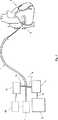
図1には、その末端2が心房を介して心臓3の冠状静脈洞内に導入された多数管腔カテーテル1を示す、冠状静脈洞を間欠的に閉塞する装置の概略図が図示されている。カテーテル1の基端4は、ポンプ6と接続されたバルーン拡張管腔5を有している。カテーテル1の末端2にて優勢な圧力は、測定された圧力値の記憶装置を含む圧力測定手段7によって決定される。それぞれ測定された圧力値は、管路9を介して制御信号を供給しポンプ6を始動させ且つ停止させる回路を備える制御手段8に供給される。圧力測定手段7は、自動式コントローラ10と更に接続されており、該自動式コントローラは、更なるポンプ11を制御し且つカテーテル1の更なる管腔12を介してポンプ11により供給される灌流液の量を調節する作用を果たす。Hereinafter, the present invention will be described in more detail with reference to the drawings.
FIG. 1 shows a schematic view of a device for intermittently occluding a coronary sinus, showing a multi-lumen catheter 1 whose distal end 2 has been introduced into the coronary sinus of the heart 3 via the atria. . The proximal end 4 of the catheter 1 has a balloon expansion lumen 5 connected to a
図2は、異なる状況における心臓組織の状態の比較図である。図2aには、心臓組織13が動脈15、16、17を介して動脈側14から十分に供給される正常な状況が図示されている。静脈は、参照番号18、19、20で概略図的に表示されている。図2bには、中央動脈16が閉じられ又は狭小となった虚血性状況が図示されている。関連する組織領域には、血液が不十分な程度にしか供給されないか又は全く供給されない。虚血性領域内へ逆行性灌流は行われない。図2cには、本発明を適用することに基づく状況が図示されている。動脈16は再度閉じられ、それぞれの組織部分に対し十分な供給は行われない。しかし、矢印21で概略図的に示すように、血液は静脈側から虚血性領域内に逆方向に注入され、静脈の閉塞は、参照番号22で概略図的に示されている。 FIG. 2 is a comparison diagram of the state of heart tissue in different situations. FIG. 2 a illustrates the normal situation in which the
図3は図2cの拡大図であり、この図から静脈内の圧力の推移及び圧力と共に、虚血性領域内への逆方向注入した血液の逆流が増すことが明らかである。灌流液が矢印21の方向に向けて組織に入るときに通る閉じた動脈16及び静脈19を再度見ることができる。閉塞する間、図3の右側に示した圧力推移は、閉塞した静脈内で測定され、到達する虚血性領域の量は、圧力最高値の上昇に伴って増大する。 FIG. 3 is an enlarged view of FIG. 2c, from which it is clear that the reverse flow of the blood injected backward into the ischemic region increases with the change in pressure in the vein and the pressure. The
図4には、測定手段7によって検出された圧力推移が示されており、閉塞の開始時は参照符号T0で示してある。一連の心臓収縮圧力最高値23及び一連の心臓拡張最低値24を見ることができる。心拍のパルス期間25は、連続的な最高値又は連続的な最低値の間の時間で示してある。心臓収縮圧力最高値は、等式Ps(t)=As(1−e−t/Ts)の指数関数曲線26内に導入することができ、ここで、Asは圧力最高値の漸近プラトー値を表し、Tsはプラトー値に達する迄の時間である。同様に、心臓拡張圧力の最低値を等式Pd(t)=Ad(1−e−t/Td)の指数関数曲線27に導入することができ、ここで、Adは圧力最低の漸近プラトー値を表し、Tdはプラトー値に達する迄の時間である。図4に示した心臓収縮及び心臓拡張圧力曲線26、27は、健常な心臓の曲線又は所定の値の曲線に相応すると想定するならば、参照番号28、29で示すようなより平坦な曲線推移は、冠状血管が介入措置によって一時的に閉じられ又は合併症のため更に長時間閉じられる状況に相応するものとして表すことができる。曲線28、29のプラトー値はより低く、より長時間の後にそのプラトー値に達することは明らかである。本発明におけるように閉塞した冠状静脈洞内に追加的な灌流液を導入することによって、曲線28、29は、標的領域に対して十分な逆行性供給が完全に確保されるように、曲線26、27の水準まで上昇するはずである。FIG. 4 shows the pressure transition detected by the measuring means 7 and is indicated by the reference symbol T0 at the start of the closure. A series of maximum
図5には、心臓収縮圧力曲線26のみが図示されており、この場合、t1にて閉塞を解放するときから、閉塞が再度、開始する時点t2に達し、そのとき、サイクルが繰り返される迄、局部的な圧力最高値の曲線は下降して基準値に戻ることは明らかである。 In FIG. 5, only the
図6には、冠状動脈における介入の全期間に亙る圧力プラトー値の推移が示されている。心臓収縮圧力プラトー値の推移は、参照番号30で示され、心臓拡張圧力プラトー値の推移は参照番号31で示してあり、介入は時点32にて終了し、冠状動脈の閉塞が解放される。 FIG. 6 shows the change in pressure plateau value over the entire period of intervention in the coronary artery. The transition of the systolic pressure plateau value is indicated by
図7には、全介入期間に亙って圧力プラトー値の90%に達する時間の推移(「90%の上昇時間」)が表されており、平均値は参照番号33で示してある。介入の開始時の小さい値から開始して時点32にて介入が終了したとき、実質的に一定のままになる値に達する迄、ステップ状に上昇することを観察することができる。 FIG. 7 shows the transition of the time to reach 90% of the pressure plateau value (“90% rise time”) over the entire intervention period, the average value being indicated by
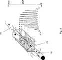
図8乃至図10には、本発明と共に使用すべき多数管腔バルーンカテーテルが図示されている。
図8において、カテーテル1の末端は参照番号2で示されている。管腔の数に依存して、異なる出口開口部34、35、36又は37を異なる管腔と接続することができ、従って、例えば、管腔内に保持された流体柱を介して測定した圧力値を決定する場合と同一の仕方にて、薬理学的物質を別個に供給し又は灌注液を供給することを可能にする。カテーテルの末端2は、拡張可能なバルーン38内を封止状態で案内され、二重矢印39の方向に摺動可能とされており、シールは参照番号40で示してある。更に、圧力測定のための更なる管腔41が明らかである。FIGS. 8-10 illustrate a multi-lumen balloon catheter to be used with the present invention.
In FIG. 8, the distal end of the catheter 1 is indicated by reference numeral 2. Depending on the number of lumens,
バルーンが予め定められた位置に達した後、バルーン38は拡張させることができ、そのとき、末端2、出口開口部若しくは口部34、35、36又は37のそれぞれの適宜な位置は、末端2を二重矢印39の方向に向けてバルーン38に対して軸方向に偏位させることで調節することができる。開口部34、35、36又は37の距離が適正に選ばれたならば、口部若しくは開口部の一部分がバルーンによって封止可能に覆われるような仕方にて末端が引き込められ、自由通路すなわち開口部35、36又は37だけが周囲の流体、特に、血管の血液循環内の血液と直接接触したままである。 After the balloon has reached a predetermined position, the
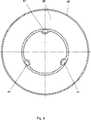
図9による図面には、その外皮を参照番号42で示したバルーン38が示してある。カテーテルの偏位可能な部分に隣接して配置される内壁は軸方向管腔41を保持しており、それを介して、例えば、測定した圧力値を得ることができる。かかる軸方向通路41の1つ又は幾つかは、バルーン38を拡張させるべく圧力流体を供給する作用を果たすこともできる。 The drawing according to FIG. 9 shows a
図10による図面には、その個別の管腔を参照番号43、44及び45で示した多数管腔カテーテル1が図示されている。個別の管腔は、図8から明らかであるように、異なる口部すなわち開口部34、35、36又は37と接続することができ、この場合、かかる管腔内に測定センサと電気的に接触するための線を配置することも可能である。 The drawing according to FIG. 10 shows a multi-lumen catheter 1 whose individual lumens are indicated by
Claims (10)
Translated fromJapanese冠状静脈洞内に又は冠状静脈洞内に延びる静脈内に導入することのでき且つ灌流液が充填された管路と、自動式制御装置に接続された灌流ポンプとを備え、
圧力測定手段が、測定した圧力値の記憶装置と、前記の測定した圧力値から求められた少なくとも1つのパラメータを計算するための計算装置とを備え、
測定した圧力値から求められた前記パラメータを考慮することにより導入した灌流液の量の制御が行われ、
記憶装置内に保存された測定圧力値は、時間スタンプが割り当てられ且つ、記憶装置が、時間に従って流体圧力曲線の導関数を計算するための計算装置と接続され、
計算装置が、各々が時間に従った流体圧力の導関数である、一回の心拍毎に生ずる局部的な最高値及び最低値を決定する比較器回路を備え、これにより、導入された灌流液の量の制御が局部的な最高値及び/又は局部的な最低値の関数として行われることを特徴とする、装置。An apparatus comprising occlusion means for occluding the coronary sinus, control means for exciting or releasing the occlusion, and pressure measuring means for determining a prevailing fluid pressure in the coronary sinus during occlusion, comprising:
A conduit that can be introduced into or extends into a coronary sinus or into a vein that extends into the coronary sinus, and a perfusion pump connected to an automatic controller;
The pressure measurement means comprises a storage device for the measured pressure value and a calculation device for calculating at least one parameter determined from the measured pressure value;
The amount of perfusate introduced is controlled by taking into account the parameters determined from the measured pressure values,
The measured pressure value stored in the storage device is assigned a time stamp and the storage device is connected to a calculation device for calculating the derivative of the fluid pressure curve according to time,
The computing device comprises a comparator circuit that determines the local maximum and minimum values occurring at each heartbeat, each of which is a derivative of fluid pressure over time, whereby the introduced perfusate The deviceis characterized in that the control of the amount is performed as a function of a local maximum and / or a local minimum .
冠状静脈洞内に又は冠状静脈洞内に延びる静脈内に導入することのでき且つ灌流液が充填された管路と、自動式制御装置に接続された灌流ポンプとを備え、
圧力測定手段が、測定した圧力値の記憶装置と、前記の測定した圧力値から求められた少なくとも1つのパラメータを計算するための計算装置とを備え、
測定した圧力値から求められた前記パラメータを考慮することにより導入した灌流液の量の制御が行われ、
圧力測定手段が、測定した圧力値の局部的な最高値の記憶装置を備え、計算装置が連続的な心拍の圧力最高値のプラトー値を計算により推定する評価回路を備え且つ圧力最高値のプラトー値の関数として導入した灌流液の量を制御するべくポンプと協働することを特徴とする、装置。An apparatus comprising occlusion means for occluding the coronary sinus, control means for exciting or releasing the occlusion, and pressure measuring means for determining a prevailing fluid pressure in the coronary sinus during occlusion, comprising:
A conduit that can be introduced into or extends into a coronary sinus or into a vein that extends into the coronary sinus, and a perfusion pump connected to an automatic controller;
The pressure measurement means comprises a storage device for the measured pressure value and a calculation device for calculating at least one parameter determined from the measured pressure value;
The amount of perfusate introduced is controlled by taking into account the parameters determined from the measured pressure values,
The pressure measuring means comprises a storage device for the local maximum value of the measured pressure value, the calculating device comprises an evaluation circuit for calculating the plateau value of the continuous heart rate pressure by calculation and a plateau for the maximum pressure value Devicecharacterized by cooperating with a pump to control the amount of perfusate introduced as a function of value .
徴とする、請求項1乃至7の何れか1つに記載の装置。Control means, characterized in that it comprises the automatic controller for the pump and / or computing device, apparatus according to any one of claims 1 to7.
Applications Claiming Priority (2)
| Application Number | Priority Date | Filing Date | Title |
|---|---|---|---|
| AT0111301AAT410396B (en) | 2001-07-17 | 2001-07-17 | DEVICE FOR THE INTERMITTENT OCCLUSION OF THE CORONARY SINE |
| PCT/AT2002/000212WO2003008018A2 (en) | 2001-07-17 | 2002-07-17 | Method and device for the intermittent occlusion of the coronary sinus |
Publications (3)
| Publication Number | Publication Date |
|---|---|
| JP2004534619A JP2004534619A (en) | 2004-11-18 |
| JP2004534619A5 JP2004534619A5 (en) | 2005-12-22 |
| JP4106019B2true JP4106019B2 (en) | 2008-06-25 |
Family
ID=3685687
Family Applications (1)
| Application Number | Title | Priority Date | Filing Date |
|---|---|---|---|
| JP2003513622AExpired - Fee RelatedJP4106019B2 (en) | 2001-07-17 | 2002-07-17 | Method and apparatus for intermittently occluding a coronary sinus |
Country Status (6)
| Country | Link |
|---|---|
| US (1) | US7331922B2 (en) |
| EP (1) | EP1406683B1 (en) |
| JP (1) | JP4106019B2 (en) |
| AT (1) | AT410396B (en) |
| DE (1) | DE50214494D1 (en) |
| WO (1) | WO2003008018A2 (en) |
Families Citing this family (36)
| Publication number | Priority date | Publication date | Assignee | Title |
|---|---|---|---|---|
| US7130700B2 (en)* | 2002-11-19 | 2006-10-31 | Medtronic, Inc. | Multilumen body for an implantable medical device |
| US7722596B2 (en)* | 2004-02-26 | 2010-05-25 | Osprey Medical, Inc. | Regional cardiac tissue treatment |
| AT500676B1 (en)* | 2004-06-08 | 2007-04-15 | Mohl Werner Ddr | DEVICE FOR THE INTERMITTENT OCCLUSION OF THE KORONARSINUS |
| AT500688B1 (en) | 2004-06-14 | 2007-04-15 | Mohl Werner Ddr | DEVICE FOR THE INTERMITTENT OCCLUSION OF THE KORONARSINUS |
| US7935075B2 (en)* | 2005-04-26 | 2011-05-03 | Cardiac Pacemakers, Inc. | Self-deploying vascular occlusion device |
| JP4809894B2 (en) | 2005-07-29 | 2011-11-09 | シーブイデバイシズ リミテッド ライアビリティ カンパニー | Apparatus and method for controlling blood pressure using a reverse perfusion cannula |
| EP1917054A4 (en) | 2005-08-25 | 2010-12-22 | Osprey Medical Inc | Devices and methods for perfusing an organ |
| US8152786B2 (en)* | 2006-11-07 | 2012-04-10 | Osprey Medical, Inc. | Collection catheter and kit |
| AT503787B1 (en)* | 2006-11-30 | 2008-01-15 | Mohl Werner Ddr | Method for intermittent occlusion of coronary sinus in heart of patient, involves releasing occlusion of coronary sinus as function of one characteristic value derived from pressure values in occluded coronary sinus |
| US8262672B2 (en) | 2008-04-16 | 2012-09-11 | Medtronic, Inc. | Medical delivery device construction |
| US9050400B2 (en)* | 2008-08-12 | 2015-06-09 | Osprey Medical, Inc. | Remote sensing catheter system and methods |
| US20100041984A1 (en)* | 2008-08-12 | 2010-02-18 | James Edward Shapland | Impedance sensing device and catheter system |
| AT507578B1 (en)* | 2008-11-27 | 2011-06-15 | Miracor Medical Systems Gmbh | IMPLANTABLE DEVICE FOR THE INTERMITTENT OCCLUSION OF A BLOOD VESSEL |
| US8626316B2 (en)* | 2009-04-03 | 2014-01-07 | Miracor Medical Systems Gmbh | Device for the intermittent occlusion of the coronary sinus |
| US9295816B2 (en)* | 2009-12-09 | 2016-03-29 | Osprey Medical, Inc. | Catheter with distal and proximal ports |
| PL2359891T3 (en) | 2010-02-16 | 2013-06-28 | Miracor Medical Systems Gmbh | Control and inflation device for a balloon catheter |
| EP2361642B1 (en) | 2010-02-19 | 2013-09-25 | Miracor Medical Systems GmbH | Implantable device for intermittent occlusion of a blood vessel |
| JP5808525B2 (en)* | 2010-02-23 | 2015-11-10 | ミラコー メディカル システムズ ゲーエムベーハー | Implantable device for intermittent occlusion of blood vessels |
| US10743780B2 (en) | 2010-05-25 | 2020-08-18 | Miracor Medical Sa | Catheter system and method for occluding a body vessel |
| EP2389974B1 (en)* | 2010-05-25 | 2014-04-23 | Miracor Medical Systems GmbH | A balloon catheter for introduction into a body vessel, in particular the coronary sinus |
| US11337707B2 (en)* | 2010-05-25 | 2022-05-24 | Miracor Medical Sa | Treating heart tissue |
| US8267887B2 (en) | 2010-05-26 | 2012-09-18 | Miracor Medical Systems Gmbh | Treating heart tissue |
| US8449565B2 (en) | 2011-07-21 | 2013-05-28 | Francis Duhay | Approaches to venous occlusion for embolus management |
| WO2013023126A2 (en) | 2011-08-11 | 2013-02-14 | Osprey Medical Inc. | Systems and methods for limb treatment |
| US10118020B2 (en)* | 2011-12-07 | 2018-11-06 | Traumatek Solutions B.V. | Devices and methods for endovascular access and therapy |
| US8177704B1 (en) | 2011-12-22 | 2012-05-15 | Miracor Medical Systems Gmbh | System and method for treating heart tissue |
| US10071243B2 (en) | 2013-07-31 | 2018-09-11 | Medtronic, Inc. | Fixation for implantable medical devices |
| US9855049B2 (en) | 2013-12-11 | 2018-01-02 | Miracor Medical Systems Gmbh | System and method for treating heart tissue |
| EP3313289B1 (en) | 2015-06-23 | 2021-03-17 | Traumatek Solutions B.V. | Vessel cannulation device |
| US10099050B2 (en) | 2016-01-21 | 2018-10-16 | Medtronic, Inc. | Interventional medical devices, device systems, and fixation components thereof |
| US10463853B2 (en) | 2016-01-21 | 2019-11-05 | Medtronic, Inc. | Interventional medical systems |
| CN108472485B (en) | 2016-01-26 | 2021-07-30 | 美敦力公司 | Compact Implantable Medical Devices and Delivery Devices |
| US11759632B2 (en) | 2019-03-28 | 2023-09-19 | Medtronic, Inc. | Fixation components for implantable medical devices |
| WO2022214851A1 (en)* | 2021-04-08 | 2022-10-13 | Miracor Medical Sa | Systems, programs and methods for determining when to terminate a coronary sinus occlusion treatment |
| CN116158800B (en)* | 2023-02-15 | 2024-07-12 | 乐普(北京)医疗器械股份有限公司 | Coronary sinus pulse saccule control method and control device |
| WO2025202288A1 (en) | 2024-03-26 | 2025-10-02 | Ng Consulting Srl | System for optimizing epicardial perfusion hemodynamics |
Family Cites Families (10)
| Publication number | Priority date | Publication date | Assignee | Title |
|---|---|---|---|---|
| US4493697A (en)* | 1979-05-10 | 1985-01-15 | Krause Horst E | Method and apparatus for pumping blood within a vessel |
| US5033998A (en)* | 1984-01-20 | 1991-07-23 | Eliot Corday | Retrograde delivery of pharmacologic and diagnostic agents via venous circulation |
| US4689041A (en)* | 1984-01-20 | 1987-08-25 | Eliot Corday | Retrograde delivery of pharmacologic and diagnostic agents via venous circulation |
| US4934996A (en)* | 1984-02-27 | 1990-06-19 | Boston Scientific Corporation | Pressure-controlled intermittent coronary sinus occlusion apparatus and method |
| US4887608A (en) | 1986-01-31 | 1989-12-19 | Boston Scientific Corporation | Method and apparatus for estimating tissue damage |
| US4969470A (en)* | 1984-02-27 | 1990-11-13 | Boston Scientific Corporation | Heart analysis using pressure-controlled intermittent coronary sinus occlusion |
| US5024668A (en)* | 1987-01-20 | 1991-06-18 | Rocky Mountain Research, Inc. | Retrograde perfusion system, components and method |
| US5505698A (en)* | 1993-10-29 | 1996-04-09 | Medtronic, Inc. | Cardioplegia catheter with elongated cuff |
| DE19514638C2 (en)* | 1995-04-20 | 1998-06-04 | Peter Dr Med Boekstegers | Device for the selective suction and retroinfusion of a fluid from or into body veins controlled by venous pressure |
| US6090096A (en)* | 1997-04-23 | 2000-07-18 | Heartport, Inc. | Antegrade cardioplegia catheter and method |
- 2001
- 2001-07-17ATAT0111301Apatent/AT410396B/ennot_activeIP Right Cessation
- 2002
- 2002-07-17EPEP02759855Apatent/EP1406683B1/ennot_activeExpired - Lifetime
- 2002-07-17WOPCT/AT2002/000212patent/WO2003008018A2/enactiveApplication Filing
- 2002-07-17JPJP2003513622Apatent/JP4106019B2/ennot_activeExpired - Fee Related
- 2002-07-17USUS10/484,194patent/US7331922B2/ennot_activeExpired - Lifetime
- 2002-07-17DEDE50214494Tpatent/DE50214494D1/ennot_activeExpired - Lifetime
Also Published As
| Publication number | Publication date |
|---|---|
| US20040172004A1 (en) | 2004-09-02 |
| WO2003008018A2 (en) | 2003-01-30 |
| DE50214494D1 (en) | 2010-07-29 |
| ATA11132001A (en) | 2002-09-15 |
| EP1406683B1 (en) | 2010-06-16 |
| JP2004534619A (en) | 2004-11-18 |
| EP1406683A2 (en) | 2004-04-14 |
| AT410396B (en) | 2003-04-25 |
| US7331922B2 (en) | 2008-02-19 |
| WO2003008018A3 (en) | 2003-04-17 |
Similar Documents
| Publication | Publication Date | Title |
|---|---|---|
| JP4106019B2 (en) | Method and apparatus for intermittently occluding a coronary sinus | |
| US11517318B2 (en) | System and method for treating heart tissue | |
| US11717302B2 (en) | Method and device for the intermittent occlusion of the coronary sinus | |
| US10561425B2 (en) | System and method for treating heart tissue | |
| JP6050417B2 (en) | Heart tissue treatment | |
| US8715196B2 (en) | Method and device for the intermittent occlusion of the coronary sinus | |
| CN111658967B (en) | Sensor device and operation method for catheter-based treatment of myocardial microvascular occlusion | |
| US20100056849A1 (en) | Method and device for the intermittent occlusion of a vein draining the organ system | |
| ES2437680T3 (en) | Implantable device for intermittent occlusion of a blood vessel |
Legal Events
| Date | Code | Title | Description |
|---|---|---|---|
| A521 | Request for written amendment filed | Free format text:JAPANESE INTERMEDIATE CODE: A523 Effective date:20041209 | |
| A621 | Written request for application examination | Free format text:JAPANESE INTERMEDIATE CODE: A621 Effective date:20041209 | |
| A131 | Notification of reasons for refusal | Free format text:JAPANESE INTERMEDIATE CODE: A131 Effective date:20070510 | |
| A601 | Written request for extension of time | Free format text:JAPANESE INTERMEDIATE CODE: A601 Effective date:20070809 | |
| A602 | Written permission of extension of time | Free format text:JAPANESE INTERMEDIATE CODE: A602 Effective date:20070816 | |
| A02 | Decision of refusal | Free format text:JAPANESE INTERMEDIATE CODE: A02 Effective date:20070928 | |
| A521 | Request for written amendment filed | Free format text:JAPANESE INTERMEDIATE CODE: A523 Effective date:20071226 | |
| A911 | Transfer to examiner for re-examination before appeal (zenchi) | Free format text:JAPANESE INTERMEDIATE CODE: A911 Effective date:20080207 | |
| TRDD | Decision of grant or rejection written | ||
| A01 | Written decision to grant a patent or to grant a registration (utility model) | Free format text:JAPANESE INTERMEDIATE CODE: A01 Effective date:20080310 | |
| A01 | Written decision to grant a patent or to grant a registration (utility model) | Free format text:JAPANESE INTERMEDIATE CODE: A01 | |
| A61 | First payment of annual fees (during grant procedure) | Free format text:JAPANESE INTERMEDIATE CODE: A61 Effective date:20080328 | |
| R150 | Certificate of patent or registration of utility model | Free format text:JAPANESE INTERMEDIATE CODE: R150 Ref document number:4106019 Country of ref document:JP Free format text:JAPANESE INTERMEDIATE CODE: R150 | |
| FPAY | Renewal fee payment (event date is renewal date of database) | Free format text:PAYMENT UNTIL: 20110404 Year of fee payment:3 | |
| S111 | Request for change of ownership or part of ownership | Free format text:JAPANESE INTERMEDIATE CODE: R313113 | |
| FPAY | Renewal fee payment (event date is renewal date of database) | Free format text:PAYMENT UNTIL: 20110404 Year of fee payment:3 | |
| FPAY | Renewal fee payment (event date is renewal date of database) | Free format text:PAYMENT UNTIL: 20110404 Year of fee payment:3 | |
| R360 | Written notification for declining of transfer of rights | Free format text:JAPANESE INTERMEDIATE CODE: R360 | |
| FPAY | Renewal fee payment (event date is renewal date of database) | Free format text:PAYMENT UNTIL: 20110404 Year of fee payment:3 | |
| FPAY | Renewal fee payment (event date is renewal date of database) | Free format text:PAYMENT UNTIL: 20110404 Year of fee payment:3 | |
| R370 | Written measure of declining of transfer procedure | Free format text:JAPANESE INTERMEDIATE CODE: R370 | |
| S111 | Request for change of ownership or part of ownership | Free format text:JAPANESE INTERMEDIATE CODE: R313113 | |
| FPAY | Renewal fee payment (event date is renewal date of database) | Free format text:PAYMENT UNTIL: 20110404 Year of fee payment:3 | |
| R350 | Written notification of registration of transfer | Free format text:JAPANESE INTERMEDIATE CODE: R350 | |
| FPAY | Renewal fee payment (event date is renewal date of database) | Free format text:PAYMENT UNTIL: 20120404 Year of fee payment:4 | |
| R250 | Receipt of annual fees | Free format text:JAPANESE INTERMEDIATE CODE: R250 | |
| FPAY | Renewal fee payment (event date is renewal date of database) | Free format text:PAYMENT UNTIL: 20120404 Year of fee payment:4 | |
| FPAY | Renewal fee payment (event date is renewal date of database) | Free format text:PAYMENT UNTIL: 20130404 Year of fee payment:5 | |
| R250 | Receipt of annual fees | Free format text:JAPANESE INTERMEDIATE CODE: R250 | |
| FPAY | Renewal fee payment (event date is renewal date of database) | Free format text:PAYMENT UNTIL: 20130404 Year of fee payment:5 | |
| FPAY | Renewal fee payment (event date is renewal date of database) | Free format text:PAYMENT UNTIL: 20140404 Year of fee payment:6 | |
| R250 | Receipt of annual fees | Free format text:JAPANESE INTERMEDIATE CODE: R250 | |
| R250 | Receipt of annual fees | Free format text:JAPANESE INTERMEDIATE CODE: R250 | |
| R250 | Receipt of annual fees | Free format text:JAPANESE INTERMEDIATE CODE: R250 | |
| R250 | Receipt of annual fees | Free format text:JAPANESE INTERMEDIATE CODE: R250 | |
| R250 | Receipt of annual fees | Free format text:JAPANESE INTERMEDIATE CODE: R250 | |
| R250 | Receipt of annual fees | Free format text:JAPANESE INTERMEDIATE CODE: R250 | |
| R250 | Receipt of annual fees | Free format text:JAPANESE INTERMEDIATE CODE: R250 | |
| R250 | Receipt of annual fees | Free format text:JAPANESE INTERMEDIATE CODE: R250 | |
| R250 | Receipt of annual fees | Free format text:JAPANESE INTERMEDIATE CODE: R250 | |
| LAPS | Cancellation because of no payment of annual fees |