JP4103308B2 - 3D live-action video shooting and presentation system - Google Patents
3D live-action video shooting and presentation systemDownload PDFInfo
- Publication number
- JP4103308B2 JP4103308B2JP2000207583AJP2000207583AJP4103308B2JP 4103308 B2JP4103308 B2JP 4103308B2JP 2000207583 AJP2000207583 AJP 2000207583AJP 2000207583 AJP2000207583 AJP 2000207583AJP 4103308 B2JP4103308 B2JP 4103308B2
- Authority
- JP
- Japan
- Prior art keywords
- video
- camera
- stereoscopic
- live
- action
- Prior art date
- Legal status (The legal status is an assumption and is not a legal conclusion. Google has not performed a legal analysis and makes no representation as to the accuracy of the status listed.)
- Expired - Fee Related
Links
- 230000003287optical effectEffects0.000claimsdescription39
- 230000010287polarizationEffects0.000claimsdescription8
- 239000011521glassSubstances0.000claimsdescription7
- 238000003384imaging methodMethods0.000claimsdescription4
- 230000000007visual effectEffects0.000claimsdescription3
- 238000010586diagramMethods0.000description16
- 230000000694effectsEffects0.000description6
- 239000000463materialSubstances0.000description3
- 230000035807sensationEffects0.000description3
- 238000000034methodMethods0.000description2
- VYPSYNLAJGMNEJ-UHFFFAOYSA-NSilicium dioxideChemical compoundO=[Si]=OVYPSYNLAJGMNEJ-UHFFFAOYSA-N0.000description1
- 230000006870functionEffects0.000description1
- 238000005259measurementMethods0.000description1
- 239000002184metalSubstances0.000description1
- 238000000926separation methodMethods0.000description1
Images


Landscapes
- Testing, Inspecting, Measuring Of Stereoscopic Televisions And Televisions (AREA)
Description
Translated fromJapanese【0001】
【発明の属する技術分野】
本発明は、広視野角且つ高解像度の立体実写映像を撮影し且つ提示することが可能な立体実写映像撮影提示システムに関するものである。
【0002】
【従来の技術】
従来、曲率の違う2つの双曲面ミラー(又は上下対称に配置された2つの角錐ミラー)を、外側の焦点を、原点で一致するよう配置し、その原点にレンズ中心がくるようカメラを配置することにより、投影面に、計測点の2つのステレオ対が同時に投影されることにより、一度に全周囲のステレオ画像を撮影可能とした全方位ステレオ画像撮影装置が提案されている(特開平11−95344号公報参照)。
【0003】
また、背面投写型ディスプレイ装置を縦3段、横4段に積み上げてなり、上及び左右方向の視野角が広く、臨場感のある映像を提示することが可能な背面投写型マルチスクリーンディスプレイシステムが提案されている(特開平8−271979号公報参照)。
【0004】
【発明が解決しようとする課題】
上記全方位ステレオ画像撮影装置では、カメラの配置が映像観察者の視点と異なる配置になっているため、そのままでは撮影した実写映像を映像提示に用いることができず、一度何らかの記録手段に保存した後、画像処理を施す必要がある。したがって、遠隔制御等のように、撮影した実写映像を即座に観賞する用途には適用不能である。
【0005】
また、上記両公報に記載された2つの従来技術とも、実写映像を撮影するカメラと映像提示装置との対応について言及されておらず、両者が正しく対応していない場合に、観賞される映像のサイズなどに違和感が生じる問題については解決されていない。
【0006】
本発明は上記事情に鑑みて為されたものであり、その目的とするところは、広視野角且つ高解像度の立体実写映像を観賞者の視点で撮影するとともに撮影した立体実写映像を即座に観賞者に提示することが可能な立体実写映像撮影提示システムを提供することにある。
【0007】
【課題を解決するための手段】
請求項1の発明は、上記目的を達成するために、多面体からなり入射した光を所望の方向へ反射させるとともに互いの中心線が人間の左右の眼の距離に略等しい距離だけ離間して配設される一対の反射用光学部品、各反射用光学部品により各々の撮影中心点の虚像が略一致するように配置された複数台のカメラからなる2組のカメラ群を具備して立体実写映像を撮影する立体実写映像撮影装置と、各組のカメラ群に含まれる2台のカメラから出力される映像信号に基づいて立体実写映像を同一画面上に映し出す複数の映像表示手段を具備して立体実写映像撮影装置で撮影された立体実写映像を観賞者に提示する立体実写映像提示装置とを備え、立体実写映像撮影装置は、各反射用光学部品の内側に下方視野を撮影するカメラがそれぞれ設けられ、このカメラの撮影中心点が各カメラ群の撮影中心点の虚像と略一致するように配置されてなり、立体実写映像提示装置は、下方視野を撮影する各カメラから出力される映像信号に基づいて立体実写映像を同一画面上に映し出す映像表示手段を具備してなることを特徴とし、互いの中心線が人間の左右の眼の距離に略等しい距離だけ離間して配置された2つの反射用光学部品で反射された映像を2組のカメラ群により撮影することにより、観賞者の視点で立体実写映像を広視野角且つ高解像度で撮影することができ、また、立体実写映像撮影装置のカメラから出力される映像信号が立体実写映像提示装置の映像表示手段に逐次伝送されるため、立体実写映像撮影装置で撮影された立体実写映像が即座に立体実写映像提示装置で違和感なく観賞することが可能となり、さらに、鉛直方向に視野を広げることができて、より広視野の実写映像を高い解像度で撮影することが可能となる。
【0008】
請求項2の発明は、請求項1の発明において、映像表示手段は、それぞれにカメラからの映像信号が入力されるカメラと同数台の投射器と、投影された光の偏光方向を保持する部材で形成され投射器によりカメラで撮影された映像が投影される複数のスクリーンと、各スクリーンに割り当てられた2台の投射器の投射口に取り付けられ各カメラ群に応じて偏光方向が異なる偏光フィルタと、偏光フィルタと同一構成の偏光フィルタが取り付けられて観賞者に装着される偏光眼鏡とを備えたことを特徴とし、偏光眼鏡を通して見る観賞者に対して各スクリーンに投影された映像を立体実写映像として知覚させることができる。
【0009】
請求項3の発明は、請求項2の発明において、偏光フィルタとして円偏光フィルタを用いることを特徴とし、映像表示手段の画面に対する観賞者の首の傾きによらずに円偏光の回転方向で分離でき、左右の映像の混入(クロストーク)を防止することができる。
【0010】
請求項4の発明は、請求項1又は2又は3の発明において、観賞者から映像表示手段の各画面を見たときの視野角が各映像表示手段と対応するカメラの視野角と略一致するように映像表示手段の各画面が配置されることを特徴とし、カメラで撮影した映像をそのまま映像表示手段の画面に表示しても観賞者に知覚される立体映像の大きさに違和感が生じない。
【0011】
請求項5の発明は、請求項1〜4の何れかの発明において、反射用光学部品は、一面にカメラを固定する固定手段を具備したプリズムからなることを特徴とし、立体実写映像撮影装置全体の小型化を図りながら、各カメラの撮影中心点を高精度で一致させることができる。
【0012】
請求項6の発明は、請求項1〜5の何れかの発明において、立体実写映像撮影装置の各カメラから出力される映像信号に対してカメラの撮影画像を水平方向にシフトする画像処理を施した後に立体実写映像提示装置に映像信号を出力する画像処理装置を備えたことを特徴とし、画像処理装置によるシフト処理のシフト量に応じて、右眼用の映像と左眼用の映像とで視差を調整することができ、その結果、観賞者が知覚する立体実写映像の奥行き感覚の調整が可能となる。
【0013】
【発明の実施の形態】
本発明の実施形態を説明する前に、本発明の基本構成を備えた参考例について説明する。
(参考例1)
図1は本参考例の立体実写映像撮影提示システムを構成する立体実写映像撮影装置の概略構成図を示している。この立体実写映像撮影装置では、角錐状に形成された一対の反射用光学部品1A,1Bと、各反射用光学部品1A,1Bと組になる複数台(例えば3台)のカメラ2A1〜2A3,2B1〜2B3とを備え、2つの反射用光学部品1A,1Bが中心線G間の距離を通常の人間の左右の眼の距離に相当する距離分F(55mm〜75mm程度)だけ離間して配置される。ここで、各反射用光学部品1A,1Bと組になる複数台のカメラ2A1〜2A3,2B1〜2B3を総称して各々「カメラ群2A」,「カメラ群2B」と呼ぶことにする。
【0014】
反射用光学部品1A,1Bは角錐状の部材に金属膜を蒸着した角錐型のミラー(鏡)で構成される。カメラ2A1…は従来周知の構成を有するものであって、レンズ、CCD等の撮像素子、信号処理回路等を具備し、撮像した映像を電気信号(映像信号)に変換して出力する。
【0015】
ここで、反射用光学部品1Aとカメラ群2A、反射用光学部品1Bとカメラ群2Bからなる各組において、カメラ群2A,2Bに含まれる複数台のカメラ2A1〜2A3,2B1〜2B3と反射用光学部品1A,1Bとの光学的な配置について、図3及び図4を参照して説明する。図3に示すように、各カメラ2A1〜2A3,2B1〜2B3の撮影中心点P(レンズの中心点)の虚像が反射用光学部品1A,1Bの中心線G上の1点(図3における点X)に集まり、且つ図4に示すように、点Xに撮影中心点が集まった各カメラ2A1〜2A3,2B1〜2B3の虚像における視野(撮影範囲)M1〜M3が重複や死角なく隣接するように、反射用光学部品1A,1Bの三角形状の各側面に対向して配置される。
【0016】
而して、上記構成により各カメラ群2A,2Bで死角や重複なく広視野の実写映像を高い解像度で撮影することが可能となり、さらに2つのカメラ群2A,2Bを人間の左右の眼の距離に相当する距離分だけ離間して配置することにより、通常の人間の視点から見たときの立体映像が撮影可能となる。
【0017】
一方、本参考例の立体実写映像撮影提示システムを構成する立体実写映像提示装置の概略構成図を図2に示す。この立体実写映像提示装置では、観賞者Hの前方及び側方を囲むように配置される3つのスクリーン11A,11B,11Cと、各スクリーン11A〜11Cに背面側から映像を投射する各一対の投射器(プロジェクタ)12A1〜12A3,12B1〜12B3とを備え、全体として投射器12A1〜12A3,12B1〜12B3をカメラ2A1〜2A3,2B1〜2B3と同数とし、スクリーン11A〜11Cをカメラ2A1〜2A3,2B1〜2B3の半数としている。なお、投射器12A1…としては従来周知の構成を有するものが使用可能であるから詳しい説明は省略する。
【0018】
各スクリーン11A、,11B,11Cに割り当てられた2台の投射器12A1と12B1,12A2と12B2,12A3と12B3は、図5に示すように、それぞれの投射口に互いに偏光方向が異なる偏光フィルタ13a,13bが取り付けられ、2台の投射器12A1と12B1,…から投射される投射光がスクリーン11A,…上でぴったりと重なって投影されるように、例えば上下に並べて配置される。また、スクリーン11A,…は投影された光の偏光方向を保持することが可能な素材で構成される。そして、観賞者は左右それぞれに上記偏光フィルタ13a,13bと同一構成の偏光フィルタが取り付けられた偏光眼鏡14を装着してスクリーン11A〜11Cに投影された映像を見ることにより、視差のついた立体映像を観賞することができる。
【0019】
ところで、立体実写映像撮影装置の各カメラ2A1〜2A3,2B1〜2B3と、立体実写映像提示装置の各投射器12A1〜12A3,12B1〜12B3とは、同じ符号(2Anと12An、2Bnと12Bn、但しn=1,2,3)同士がケーブル等によって電気的に接続され、各カメラ2A1〜2A3,2B1〜2B3から出力される映像信号がケーブル等を介して各投射器12A1〜12A3,12B1〜12B3に伝送される。ここで、ケーブル等で接続されるカメラ2An,2Bnと投射器12An,12Bnとは、カメラ2An,2Bnの視野の方向と、投射器12An,12Bnが映像を投射するスクリーン11A,11B,11Cを観賞者Hから見たときの方向とが一致するように対応づけられている。また、投射器12An,12Bnの投射口に取り付けられる偏光フィルタ13a,13bは、取り付けられるカメラ2An,2Bnが右眼用の映像を撮影するカメラ群2Aに属するか、左眼用の映像を撮影するカメラ群2Bに属するかに応じて、観賞者Hが装着する偏光眼鏡14の右眼又は左眼に用いた偏光フィルタと同一構成のもの(偏光方向が一致するもの)が用いられる。
【0020】
上述のように構成された本参考例の立体実写映像撮影提示システムでは、立体実写映像撮影装置のカメラ2An,2Bnから出力される映像信号が立体実写映像提示装置の投射器12An,12Bnに逐次伝送されるため、立体実写映像撮影装置で撮影された立体実写映像が即座に立体実写映像提示装置で違和感なく観賞することが可能となる。
【0021】
ところで、投射器12An,12Bnの投射口に取り付ける偏光フィルタ及び観賞者Hが装着する偏光眼鏡14に用いる偏光フィルタとしては、円偏光フィルタを用いるのが望ましい。円偏光フィルタは、4分の1波長板と直線偏光フィルタを組み合せて構成されるフィルタで、右回りあるいは左回りの円偏光のうち、何れか一方の回転方向の円偏光のみを通す機能を有するフィルタである。すなわち、この円偏光フィルタ13a,13bを投射器12An,12Bnの投射口に取り付けることにより、投射器12An,12Bnの投射光は右回りあるいは左回りとなり、さらにこの投射光を円偏光フィルタを用いた偏光眼鏡14を装着して観賞すれば、右眼及び左眼で見る映像の分離がスクリーン11A〜11Cに対する観賞者Hの首の傾きによらずに円偏光の回転方向で分離できるので、投射器12An,12Bnからの投射光を確実に左右に分離することができ、左右の映像が混入(クロストーク)するのを防止することができる。
【0022】
(参考例2)
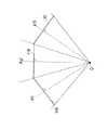
本参考例は、立体実写映像提示装置における3枚のスクリーン11A,11B,11Cを、図6及び図7に示すように各スクリーン11A〜11Cの中心を通る法線K1〜K3が一点Oで交叉し、且つこの交叉点Oから各スクリーン11A〜11Cを見込む角度N1〜N3が立体実写映像撮影装置における各カメラ2An,2Bnの視野角M1〜M3と一致するように配置する点に特徴がある。なお、これ以外の構成は参考例1と共通であるから図示並びに説明は省略する。
【0023】
観賞者Hは、図7に示すように上記交叉点Oからスクリーン11A〜11Cに投影される映像を観賞する。また、投射器12An,12Bnは、上述のように配置された各スクリーン11A〜11Cに対して画面一杯に映像が投影されるような後方の位置に配置される。
【0024】
而して、上記構成によれば、カメラ2An,2Bnで撮影した映像をそのままスクリーン11A〜11Cに投影しても、観賞者Hに知覚される立体映像の大きさに違和感が生じないという利点がある。
【0025】
(参考例3)
本参考例は、立体実写映像撮影装置における反射用光学部品の構造に特徴があり、これ以外の構成は参考例1と共通であるから図示並びに説明は省略する。
【0026】
本参考例における反射用光学部品3は、石英ガラス等の透光性材料製のプリズムからなり、図8及び図9に示すように四角錐をその1つの底辺を含み底辺に平行でない平面で切り取った形状に形成され、斜面3aと対向する底面3bの略中央に円筒形の凹所3cが設けられている。そして、この凹所3c内にカメラ2An,2Bnのレンズ先端部分が挿入されることで反射用光学部品3にカメラ2An,2Bnが固定されることになる。ここで、斜面3aと底面3bに隣り合う反射用光学部品3の前面3dからカメラ2An,2Bnの視野角M1〜M3内に入射する光が、全て反射用光学部品3の内面で全反射するように透光性材料の屈折率及び斜面3aの角度が設定されている。
【0027】
而して、プリズムからなる反射用光学部品3の凹所3cにレンズ先端部分を挿入してカメラ2An,2Bnを固定するようにしているから、立体実写映像撮影装置全体の小型化を図りながら、各カメラ2An,2Bnの撮影中心点Pを高精度で一致させることができる。
【0028】
(参考例4)
本参考例は、図10に示すように立体実写映像撮影装置の各カメラ2An,2Bnから出力される映像信号に対して画像処理を施す画像処理装置10を備えた点に特徴があり、これ以外の構成は参考例1と共通であるから図示並びに説明は省略する。
【0029】
画像処理装置は従来周知の構成を有し、図11に示すようにカメラ2An,2Bnで撮影された撮影画像Wの1フレーム分をメモリに蓄積し、1フレームの画像Wを水平方向に所望の距離だけ移動(シフト)する処理を行った後、そのシフト処理後の1フレーム分の画像(映像信号)W’を立体実写映像提示装置の各投射器12An,12Bnに出力するものである。
【0030】
而して、画像処理装置によるシフト処理のシフト量に応じて、右眼用の映像と左眼用の映像とで視差を調整することができ、その結果、観賞者Hが知覚する立体実写映像の奥行き感覚の調整が可能となる。
【0031】
(実施形態)
本実施形態の基本構成は参考例1と共通であり、共通する部分については同一の符号を付して説明を省略する。
【0032】
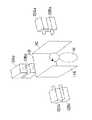
本実施形態の立体実写映像撮影装置では、図12に示すように角錐状の反射用光学部品1A,1Bに設けた内部スペースに、下方を撮影するためのカメラ2A4,2B4が配置されている。このようなスペースを設けるには、肉厚の薄い板状の鏡やプリズムを組み合わせることで角錐の側面の一面(例えば、視野の後方に相当する面)を除去したような形状に反射用光学部品1A,1Bを形成すればよい。
【0033】
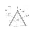
ここで、追加されたカメラ2A4,2B4と反射用光学部品1A,1Bとの光学的な配置について、図13を参照して説明する。図13に示すように、各カメラ2A1〜2A3,2B1〜2B3の撮影中心点Pの虚像が集まった反射用光学部品1A,1Bの中心線G上の点Xと、追加されたカメラ2A4,2B4の撮影中心点Pとが一致するとともに、追加されたカメラ2A4,2B4の視野(撮影範囲)M4が、追加されたカメラ2A4,2B4と上下方向で隣接するカメラ2A2,2B2の視野M2と重複や死角が生じることなく隣接するように、反射用光学部品1A,1Bに設けた内部スペースに各カメラ2A4,2B4が配置される。
【0034】
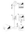
一方、本実施形態の立体実写映像提示装置では、図14に示すように観賞者Hから見てスクリーン11A〜11Cの下方に配置されたスクリーン11Dと、スクリーン11Dの背面側に設置され、追加されたカメラ2A4,2B4からの映像信号が各々入力される2台の投射器12A4,12B4とが追加されている。追加されたスクリーン11Dは、図15に示すように中心を通る法線K4が実施形態2で説明した交叉点Oを通り、且つ法線K4の方向が、割り当てられたカメラ2A4,2B4の光軸と対応するように配置される。なお、2台の投射器12A4,12B4とカメラ2A4,2B4との対応関係、および投射器12A4,12B4の投射口に取り付けられる偏光フィルタの左右の別は参考例1〜3に準じる。
【0035】
而して、本実施形態によれば鉛直方向に視野を広げることができ、より広視野の実写映像を高い解像度で撮影することが可能となる。
【0036】
【発明の効果】
請求項1の発明は、多面体からなり入射した光を所望の方向へ反射させるとともに互いの中心線が人間の左右の眼の距離に略等しい距離だけ離間して配設される一対の反射用光学部品、各反射用光学部品により各々の撮影中心点の虚像が略一致するように配置された複数台のカメラからなる2組のカメラ群を具備して立体実写映像を撮影する立体実写映像撮影装置と、各組のカメラ群に含まれる2台のカメラから出力される映像信号に基づいて立体実写映像を同一画面上に映し出す複数の映像表示手段を具備して立体実写映像撮影装置で撮影された立体実写映像を観賞者に提示する立体実写映像提示装置とを備え、立体実写映像撮影装置は、各反射用光学部品の内側に下方視野を撮影するカメラがそれぞれ設けられ、このカメラの撮影中心点が各カメラ群の撮影中心点の虚像と略一致するように配置されてなり、立体実写映像提示装置は、下方視野を撮影する各カメラから出力される映像信号に基づいて立体実写映像を同一画面上に映し出す映像表示手段を具備してなるので、互いの中心線が人間の左右の眼の距離に略等しい距離だけ離間して配置された2つの反射用光学部品で反射された映像を2組のカメラ群により撮影することにより、観賞者の視点で立体実写映像を広視野角且つ高解像度で撮影することができ、また、立体実写映像撮影装置のカメラから出力される映像信号が立体実写映像提示装置の映像表示手段に逐次伝送されるため、立体実写映像撮影装置で撮影された立体実写映像が即座に立体実写映像提示装置で違和感なく観賞することが可能となり、さらに、鉛直方向に視野を広げることができて、より広視野の実写映像を高い解像度で撮影することが可能となるという効果がある。
【0037】
請求項2の発明は、請求項1の発明において、映像表示手段は、それぞれにカメラからの映像信号が入力されるカメラと同数台の投射器と、投影された光の偏光方向を保持する部材で形成され投射器によりカメラで撮影された映像が投影される複数のスクリーンと、各スクリーンに割り当てられた2台の投射器の投射口に取り付けられ各カメラ群に応じて偏光方向が異なる偏光フィルタと、偏光フィルタと同一構成の偏光フィルタが取り付けられて観賞者に装着される偏光眼鏡とを備えたので、偏光眼鏡を通して見る観賞者に対して各スクリーンに投影された映像を立体実写映像として知覚させることができるという効果がある。
【0038】
請求項3の発明は、請求項2の発明において、偏光フィルタとして円偏光フィルタを用いるので、映像表示手段の画面に対する観賞者の首の傾きによらずに円偏光の回転方向で分離でき、左右の映像の混入(クロストーク)を防止することができるという効果がある。
【0039】
請求項4の発明は、請求項1又は2又は3の発明において、観賞者から映像表示手段の各画面を見たときの視野角が各映像表示手段と対応するカメラの視野角と略一致するように映像表示手段の各画面が配置されるので、カメラで撮影した映像をそのまま映像表示手段の画面に表示しても観賞者に知覚される立体映像の大きさに違和感が生じないという効果がある。
【0040】
請求項5の発明は、請求項1〜4の何れかの発明において、反射用光学部品は、一面にカメラを固定する固定手段を具備したプリズムからなるので、立体実写映像撮影装置全体の小型化を図りながら、各カメラの撮影中心点を高精度で一致させることができるという効果がある。
【0041】
請求項6の発明は、請求項1〜5の何れかの発明において、立体実写映像撮影装置の各カメラから出力される映像信号に対してカメラの撮影画像を水平方向にシフトする画像処理を施した後に立体実写映像提示装置に映像信号を出力する画像処理装置を備えたので、画像処理装置によるシフト処理のシフト量に応じて、右眼用の映像と左眼用の映像とで視差を調整することができ、その結果、観賞者が知覚する立体実写映像の奥行き感覚の調整が可能となるという効果がある。
【図面の簡単な説明】
【図1】本発明の参考例1における立体実写映像撮影装置を示す概略構成図である。
【図2】 同上における立体実写映像提示装置を示す概略構成図である。
【図3】 同上における立体実写映像撮影装置の反射用光学部品とカメラとの光学的配置を説明するための説明図である。
【図4】 同上における立体実写映像撮影装置の動作説明図である。
【図5】 同上における立体実写映像提示装置の動作説明図である。
【図6】参考例2における立体実写映像提示装置の動作説明図である。
【図7】 同上における立体実写映像提示装置の動作説明図である。
【図8】参考例3における立体実写映像撮影装置の一部省略した概略構成図である。
【図9】 同上における立体実写映像撮影装置の一部省略した断面図である。
【図10】参考例4を示す概略構成図である。
【図11】 同上の動作説明図である。
【図12】本発明の実施形態における立体実写映像撮影装置を示す概略構成図である。
【図13】 同上における立体実写映像撮影装置の反射用光学部品とカメラとの光学的配置を説明するための説明図である。
【図14】 同上における立体実写映像提示装置を示す概略構成図である。
【図15】 同上の動作説明図である。
【符号の説明】
1A,1B 反射用光学部品
2A,2B カメラ群
2A1〜2A3,2B1〜2B3 カメラ
11A〜11C スクリーン
12A1〜12A3,12B1〜12B3 投射器[0001]
BACKGROUND OF THE INVENTION
The present invention relates to a three-dimensional real image photographing / presentation system capable of photographing and presenting a three-dimensional real image having a wide viewing angle and high resolution.
[0002]
[Prior art]
Conventionally, two hyperboloid mirrors with different curvatures (or two pyramid mirrors arranged vertically symmetrically) are arranged so that the outer focal points coincide with each other at the origin, and the camera is arranged so that the lens center comes to the origin. Thus, there has been proposed an omnidirectional stereo image photographing apparatus capable of photographing a stereo image of the entire circumference at once by projecting two stereo pairs of measurement points onto the projection surface at the same time (Japanese Patent Laid-Open No. Hei 11- No. 95344).
[0003]
Also, there is a rear projection type multi-screen display system in which rear projection type display devices are stacked in three vertical rows and four horizontal rows, have wide viewing angles in the upper and left and right directions, and can present realistic images. It has been proposed (see JP-A-8-271979).
[0004]
[Problems to be solved by the invention]
In the above-mentioned omnidirectional stereo image capturing device, the camera is arranged differently from the viewpoint of the video observer, so the photographed video cannot be used for video presentation as it is, and is once stored in some recording means. After that, it is necessary to perform image processing. Therefore, it cannot be applied to a purpose of instantly viewing a photographed real image such as remote control.
[0005]
In addition, neither of the two prior arts described in the above-mentioned publications mentions the correspondence between a camera that captures a live-action video and a video presentation device. The problem of uncomfortable size has not been solved.
[0006]
The present invention has been made in view of the above circumstances, and an object of the present invention is to shoot a stereoscopic video image having a wide viewing angle and a high resolution from the viewpoint of the viewer and instantly view the captured stereoscopic video image. The present invention provides a stereoscopic live-action video shooting and presentation system that can be presented to a person.
[0007]
[Means for Solving the Problems]
In order to achieve the above object, the invention of claim 1 is configured to reflect incident light made of a polyhedron in a desired direction, and the center lines of the polyhedrons are spaced apart by a distance substantially equal to the distance between the left and right eyes of a human. A pair of reflecting optical parts, and a stereoscopic live-action image comprising two sets of camera groups including a plurality of cameras arranged so that the virtual images of the respective photographing center points substantially coincide with each other by the reflecting optical parts A stereoscopic live-action video photographing device for photographing a three-dimensional real-time video, and a plurality of video display means for projecting a stereoscopic live-action video on the same screen based on video signals output from two cameras included in each set of camera groups. 3D live video presentation device that presents viewers with3D live video shot by the live video shooting device, and each 3D live video shooting device is provided with a camera that shoots the lower field of view inside each reflective optical component Et The camera center point of the camera is arranged so as to substantially coincide with the virtual image of the camera center point of each camera group, and the stereoscopic video display device is based on the video signal output from each camera that captures the lower field of view. And a video display means for projecting a three-dimensional live-action video on the same screen, and the two center lines are arranged so that their centerlines are separated by a distance substantially equal to the distance between the left and right eyes of a human being. By photographing the images reflected by the optical components with two sets of cameras, it is possible to shoot a stereoscopic live-action image with a wide viewing angle and high resolution from the viewpoint of the viewer. Since the video signal output from the 3D live-action video presentation device is sequentially transmitted to the video display means, the 3D live-action video shot by the 3D live-action video shooting device can be immediately viewed without any sense of incongruity. Itbecomes possible tofurther be able to widen the field of view in the vertical direction, itis possible to photograph the photographed image of a wider field of view with high resolution.
[0008]
According to a second aspect of the present invention, in the first aspect of the present invention, the video display means includes the same number of projectors as the cameras to which video signals from the cameras are input, and a member that holds the polarization direction of the projected light. A plurality of screens on which images projected by a projector and projected by a camera are projected, and polarizing filters attached to projection ports of twoprojectors assigned to each screen and having different polarization directions depending on each camera group A polarizing filter having the same configuration as that of the polarizing filter and attached to the viewer, and a stereoscopic live-action image projected on each screen to the viewer looking through the polarizing glasses. It can be perceived as a video.
[0009]
According to a third aspect of the present invention, in the second aspect of the present invention, a circular polarizing filter is used as the polarizing filter, and the light is separated in the rotational direction of the circularly polarized light regardless of the inclination of the viewer's neck with respect to the screen of the image display means. And mixing of the left and right images (crosstalk) can be prevented.
[0010]
According to a fourth aspect of the present invention, in the first, second, or third aspect of the invention, the viewing angle when the viewer views each screen of the video display means substantially matches the viewing angle of the camera corresponding to each video display means. The screens of the video display means are arranged as described above, and even if the video shot by the camera is displayed on the screen of the video display means as it is, there is no sense of incongruity in the size of the stereoscopic video perceived by the viewer. .
[0011]
According to a fifth aspect of the present invention, in any of the first to fourth aspects of the present invention, the reflecting optical component comprises a prism having a fixing means for fixing the camera on one surface, and the entire stereoscopic live-action image photographing device The center of photographing of each camera can be matched with high accuracy while downsizing.
[0012]
According to a sixth aspect of the present invention, in any one of the first to fifth aspects of the present invention, image processing for shifting the image captured by the camera in the horizontal direction is performed on the video signal output from each camera of the stereoscopic video image capturing apparatus. After that, an image processing device that outputs a video signal to the stereoscopic live image presentation device is provided, and depending on the shift amount of the shift processing by the image processing device, the right eye video and the left eye video The parallax can be adjusted, and as a result, the depth sensation of the stereoscopic video image perceived by the viewer can be adjusted.
[0013]
DETAILED DESCRIPTION OF THE INVENTION
Before describing an embodiment of the present invention, a reference example having the basic configuration of the present invention will be described.
(Reference Example 1)
FIG. 1 is a schematic configuration diagram of a stereoscopic live-action video shooting apparatus that constitutes the stereoscopic real-time video shooting and presentation system of thisreference example . In this stereoscopic video camera, a pair of reflective
[0014]
The reflecting
[0015]
Here, a plurality of
[0016]
Thus, the
[0017]
On the other hand, FIG. 2 shows a schematic configuration diagram of a stereoscopic live-action video presenting apparatus constituting the stereoscopic real-time video shooting / presentation system of the presentreference example . In this three-dimensional live-action image presentation device, three
[0018]
As shown in FIG. 5,two projectors 12A1 and 12B1 , 12A2 and 12B2 , and 12A3 and 12B3 assigned to the
[0019]
Incidentally, the
[0020]
In the stereoscopic live-action video shooting and presentation system of the presentreference example configured as described above, video signals output from the
[0021]
By the way, it is desirable to use a circular polarizing filter as the polarizing filter attached to the projection ports of the projectors 12An and 12Bn and the polarizing filter used in the
[0022]
(Reference Example 2)
In thisreference example , three
[0023]
The viewer H views the images projected on the screens 11A to 11C from the intersection point O as shown in FIG. Further, the projectors 12An and 12Bn are arranged at rear positions so that the images are projected to the full screen on the screens 11A to 11C arranged as described above.
[0024]
Thus, according to the above configuration, even if the images taken by the
[0025]
(Reference Example 3)
Thisreference example is characterized by the structure of the reflective optical component in the stereoscopic live-action image capturing device, and the other configurations are the same as those of thereference example 1, so illustration and description thereof are omitted.
[0026]
The reflecting
[0027]
Thus, since the front end of the lens is inserted into the
[0028]
(Reference Example 4)
As shown in FIG. 10, the presentreference example is characterized in that it includes an
[0029]
The image processing apparatus has a conventionally well-known configuration. As shown in FIG. 11, one frame of the captured image W captured by the
[0030]
Thus, the parallax can be adjusted between the right-eye video and the left-eye video according to the shift amount of the shift processing by the image processing apparatus, and as a result, the stereoscopic live-action video perceived by the viewer H The depth sensation can be adjusted.
[0031]
(Embodiment)
The basic configuration of this embodiment is the same as that ofReference Example 1, and common portions are denoted by the same reference numerals and description thereof is omitted.
[0032]
In the stereoscopic live-action image capturing device of this embodiment, as shown in FIG. 12,
[0033]
Here, the optical arrangement of the added
[0034]
On the other hand, in the three-dimensional live-action image presentation device of the present embodiment, as shown in FIG. 14, the screen 11D disposed below the screens 11A to 11C as viewed from the viewer H, and the back side of the screen 11D are installed and added. Two projectors 12A4 and 12B4 to which video signals from the
[0035]
Thus, according to the present embodiment, the field of view can be expanded in the vertical direction, and it is possible to shoot a wide-field real image with high resolution.
[0036]
【The invention's effect】
According to the first aspect of the present invention, a pair of reflecting optics, which are composed of polyhedrons, reflect incident light in a desired direction and are spaced apart from each other by a distance approximately equal to the distance between the left and right human eyes. A stereoscopic live-action image photographing apparatus that has two sets of camera groups including a plurality of cameras arranged so that virtual images of respective photographing center points substantially coincide with each other by optical components for reflection and each reflection. And a plurality of video display means for projecting a stereoscopic video on the same screen based on video signals output from two cameras included in each set of camera groups. and a stereoscopic Stock video presentation device for presenting a stereoscopic Stock video toviewer, stereoscopic Stock video imaging apparatus, a camera is provided respectively to shoot LVF inside each reflective optics, imaging center point of the camera It is arranged so that it substantially matches the virtual image of the shooting center point of each camera group, and the stereoscopic live image presentation device displays the stereoscopic real video on the same screen based on the video signal output from each camera that captures the lower visual field. Since the image display means for projecting is provided , two sets of images reflected by the two reflecting optical components arranged such that their center lines are separated from each other by a distance substantially equal to the distance between the left and right eyes of a human being. By shooting with a camera group, it is possible to shoot a stereoscopic video with a wide viewing angle and high resolution from the viewer's viewpoint, and the video signal output from the camera of the stereoscopic video camera is presented as a stereoscopic video. for sequentially transmitted to the video display means of the device,it is possible to watch without discomfort stereoscopic Stock video presentation device stereoscopic live action image captured by the stereoscopic live action image capturing device inreal Furthermore, vertical To be able to widen the field of view direction, there is an effect thatit ispossible to be taken at a higher resolution Stock Video of a wider field of view.
[0037]
According to a second aspect of the present invention, in the first aspect of the present invention, the video display means includes the same number of projectors as the cameras to which video signals from the cameras are input, and a member that holds the polarization direction of the projected light. A plurality of screens on which images projected by a projector and projected by a camera are projected, and polarizing filters attached to projection ports of twoprojectors assigned to each screen and having different polarization directions depending on each camera group And polarizing glasses that are attached to the viewer with a polarizing filter having the same configuration as the polarizing filter, so that the viewer can view the images projected on each screen as stereoscopic images. There is an effect that can be made.
[0038]
In the invention of
[0039]
According to a fourth aspect of the present invention, in the first, second, or third aspect of the invention, the viewing angle when the viewer views each screen of the video display means substantially matches the viewing angle of the camera corresponding to each video display means. Since each screen of the video display means is arranged as described above, there is an effect that even if the video taken by the camera is displayed on the screen of the video display means as it is, the size of the stereoscopic video perceived by the viewer does not feel strange. is there.
[0040]
According to a fifth aspect of the present invention, in any one of the first to fourth aspects, the reflecting optical component comprises a prism having a fixing means for fixing the camera on one surface. There is an effect that the photographing center point of each camera can be matched with high accuracy.
[0041]
According to a sixth aspect of the present invention, in any one of the first to fifth aspects of the present invention, image processing for shifting the image captured by the camera in the horizontal direction is performed on the video signal output from each camera of the stereoscopic video image capturing apparatus. After that, the image processing device that outputs the video signal to the stereoscopic live image presentation device is provided, so that the parallax is adjusted between the video for the right eye and the video for the left eye according to the shift amount of the shift processing by the image processing device. As a result, it is possible to adjust the depth sensation of the stereoscopic live-action image perceived by the viewer.
[Brief description of the drawings]
FIG. 1 is a schematic configuration diagram showing a stereoscopic live-action image capturing device inReference Example 1 of thepresent invention .
[Fig. 2] Fig. 2 is a schematic configuration diagram showing a stereoscopic live-action image presenting device according to the above.
FIG. 3 is an explanatory diagram for explaining an optical arrangement of a reflection optical component and a camera of the stereoscopic live-action image photographing apparatus according to the above.
[Fig. 4] Fig. 4 is a diagram for explaining the operation of the stereoscopic live-action image capturing device of the above.
[Fig. 5] Fig. 5 is an operation explanatory diagram of the stereoscopic live-action image presentation device according to the above.
6 is an operation explanatory diagram of a stereoscopic live-action image presentation device inReference Example 2. FIG.
[Fig. 7] Fig. 7 is an operation explanatory diagram of the stereoscopic live-action image presentation device according to the above.
FIG. 8 is a schematic configuration diagram in which a part of the stereoscopic live-action image capturing device inReference Example 3 is omitted.
FIG. 9 is a cross-sectional view in which the stereoscopic live-action image capturing apparatus is partially omitted.
10 is a schematic configuration diagram showing areference example 4. FIG.
FIG. 11 is an operation explanatory diagram of the above.
12 is a schematic diagram showing the three-dimensional live action image capturing apparatus definitiveto an embodimentof the present invention.
FIG. 13 is an explanatory diagram for explaining an optical arrangement of a reflection optical component and a camera of the stereoscopic live-action image capturing device according to the embodiment;
FIG. 14 is a schematic configuration diagram showing the stereoscopic live-action image presentation device according to the above.
FIG. 15 is an operation explanatory diagram of the above.
[Explanation of symbols]
1A, 1B Reflective
Claims (6)
Translated fromJapanesePriority Applications (1)
| Application Number | Priority Date | Filing Date | Title |
|---|---|---|---|
| JP2000207583AJP4103308B2 (en) | 2000-07-07 | 2000-07-07 | 3D live-action video shooting and presentation system |
Applications Claiming Priority (1)
| Application Number | Priority Date | Filing Date | Title |
|---|---|---|---|
| JP2000207583AJP4103308B2 (en) | 2000-07-07 | 2000-07-07 | 3D live-action video shooting and presentation system |
Publications (2)
| Publication Number | Publication Date |
|---|---|
| JP2002027494A JP2002027494A (en) | 2002-01-25 |
| JP4103308B2true JP4103308B2 (en) | 2008-06-18 |
Family
ID=18704326
Family Applications (1)
| Application Number | Title | Priority Date | Filing Date |
|---|---|---|---|
| JP2000207583AExpired - Fee RelatedJP4103308B2 (en) | 2000-07-07 | 2000-07-07 | 3D live-action video shooting and presentation system |
Country Status (1)
| Country | Link |
|---|---|
| JP (1) | JP4103308B2 (en) |
Families Citing this family (2)
| Publication number | Priority date | Publication date | Assignee | Title |
|---|---|---|---|---|
| JP2006033570A (en)* | 2004-07-20 | 2006-02-02 | Olympus Corp | Image generating device |
| KR100619067B1 (en) | 2005-01-31 | 2006-08-31 | 삼성전자주식회사 | Stereoscopic projection device |
- 2000
- 2000-07-07JPJP2000207583Apatent/JP4103308B2/ennot_activeExpired - Fee Related
Also Published As
| Publication number | Publication date |
|---|---|
| JP2002027494A (en) | 2002-01-25 |
Similar Documents
| Publication | Publication Date | Title |
|---|---|---|
| JP5172972B2 (en) | 3D image display device | |
| JP4863527B2 (en) | Stereoscopic imaging device | |
| JP4057652B2 (en) | Autostereoscopic image forming apparatus and system incorporating the same | |
| CA2473375C (en) | Apparatus for stereoscopic photography | |
| JP4421673B2 (en) | 3D image display device | |
| EP0460873A1 (en) | Apparatus for displaying an image | |
| WO2009004742A1 (en) | Three-dimensional television system, three-dimensional television receiver and three-dimensional image watching glasses | |
| WO2016128157A1 (en) | Stereoscopic reproduction system using transparency | |
| JPH07504766A (en) | Image forming system with two sets of screens | |
| JP3676916B2 (en) | Stereoscopic imaging device and stereoscopic display device | |
| JP3205552B2 (en) | 3D image pickup device | |
| JPH09224265A (en) | Stereoscopic image recording method and apparatus | |
| JP4103308B2 (en) | 3D live-action video shooting and presentation system | |
| KR102172408B1 (en) | Three-dimensional image projection apparatus | |
| JP4353001B2 (en) | 3D imaging adapter | |
| KR20190083772A (en) | Three-dimensional image projection apparatus | |
| CA2194630A1 (en) | Viewing system for electronic 3-d animation and 3-d viewing mirror | |
| US20060083437A1 (en) | Three-dimensional image display apparatus | |
| JP3463960B2 (en) | 3D image display device | |
| JPH09182113A (en) | Three-dimensional solid video signal conversion device and video camera device using the device | |
| JPH0397390A (en) | Solid display device | |
| JP2707549B2 (en) | Pseudo three-dimensional video projector | |
| JP2001312018A (en) | Two-in-a-set image and stereo camera for obtaining the image | |
| JPH0879801A (en) | Stereoscopic projector | |
| WO2013061334A1 (en) | 3d stereoscopic imaging device with auto parallax |
Legal Events
| Date | Code | Title | Description |
|---|---|---|---|
| A621 | Written request for application examination | Free format text:JAPANESE INTERMEDIATE CODE: A621 Effective date:20060217 | |
| A131 | Notification of reasons for refusal | Free format text:JAPANESE INTERMEDIATE CODE: A131 Effective date:20071211 | |
| A521 | Written amendment | Free format text:JAPANESE INTERMEDIATE CODE: A523 Effective date:20080212 | |
| TRDD | Decision of grant or rejection written | ||
| A01 | Written decision to grant a patent or to grant a registration (utility model) | Free format text:JAPANESE INTERMEDIATE CODE: A01 Effective date:20080304 | |
| A61 | First payment of annual fees (during grant procedure) | Free format text:JAPANESE INTERMEDIATE CODE: A61 Effective date:20080317 | |
| FPAY | Renewal fee payment (event date is renewal date of database) | Free format text:PAYMENT UNTIL: 20110404 Year of fee payment:3 | |
| S533 | Written request for registration of change of name | Free format text:JAPANESE INTERMEDIATE CODE: R313533 | |
| FPAY | Renewal fee payment (event date is renewal date of database) | Free format text:PAYMENT UNTIL: 20110404 Year of fee payment:3 | |
| R350 | Written notification of registration of transfer | Free format text:JAPANESE INTERMEDIATE CODE: R350 | |
| FPAY | Renewal fee payment (event date is renewal date of database) | Free format text:PAYMENT UNTIL: 20130404 Year of fee payment:5 | |
| FPAY | Renewal fee payment (event date is renewal date of database) | Free format text:PAYMENT UNTIL: 20130404 Year of fee payment:5 | |
| FPAY | Renewal fee payment (event date is renewal date of database) | Free format text:PAYMENT UNTIL: 20140404 Year of fee payment:6 | |
| LAPS | Cancellation because of no payment of annual fees |