JP4102785B2 - MTF measuring method and apparatus - Google Patents
MTF measuring method and apparatusDownload PDFInfo
- Publication number
- JP4102785B2 JP4102785B2JP2004205729AJP2004205729AJP4102785B2JP 4102785 B2JP4102785 B2JP 4102785B2JP 2004205729 AJP2004205729 AJP 2004205729AJP 2004205729 AJP2004205729 AJP 2004205729AJP 4102785 B2JP4102785 B2JP 4102785B2
- Authority
- JP
- Japan
- Prior art keywords
- image
- center
- coordinates
- mtf
- lsf
- Prior art date
- Legal status (The legal status is an assumption and is not a legal conclusion. Google has not performed a legal analysis and makes no representation as to the accuracy of the status listed.)
- Expired - Lifetime
Links
Images


Classifications
- G—PHYSICS
- G01—MEASURING; TESTING
- G01M—TESTING STATIC OR DYNAMIC BALANCE OF MACHINES OR STRUCTURES; TESTING OF STRUCTURES OR APPARATUS, NOT OTHERWISE PROVIDED FOR
- G01M11/00—Testing of optical apparatus; Testing structures by optical methods not otherwise provided for
- G01M11/02—Testing optical properties
- G01M11/0292—Testing optical properties of objectives by measuring the optical modulation transfer function
- G—PHYSICS
- G06—COMPUTING OR CALCULATING; COUNTING
- G06T—IMAGE DATA PROCESSING OR GENERATION, IN GENERAL
- G06T7/00—Image analysis
- G06T7/60—Analysis of geometric attributes
- G06T7/66—Analysis of geometric attributes of image moments or centre of gravity
- G—PHYSICS
- G06—COMPUTING OR CALCULATING; COUNTING
- G06T—IMAGE DATA PROCESSING OR GENERATION, IN GENERAL
- G06T7/00—Image analysis
- G06T7/70—Determining position or orientation of objects or cameras
Landscapes
- Physics & Mathematics (AREA)
- Engineering & Computer Science (AREA)
- General Physics & Mathematics (AREA)
- Computer Vision & Pattern Recognition (AREA)
- Theoretical Computer Science (AREA)
- Chemical & Material Sciences (AREA)
- Analytical Chemistry (AREA)
- Geometry (AREA)
- Image Analysis (AREA)
- Apparatus For Radiation Diagnosis (AREA)
- Image Processing (AREA)
Description
Translated fromJapanese本発明は、MTF(modulation transfer function)測定方法および装置に関し、特に、LSF(line spread function)のフーリエ(Fourier)変換によりMTFを求める方法および装置に関する。 The present invention relates to an MTF (modulation transfer function) measuring method and apparatus, and more particularly to a method and apparatus for obtaining MTF by Fourier transform of LSF (line spread function).
MTFは変調伝達関数とも呼ばれ、X線CT装置の再構成画像の空間分解能を表すので、X線CT装置の性能評価に利用される。MTFは、再構成画像におけるLSF(line spread function)像をフーリエ変換することによって求められる(例えば、非特許文献1参照)。
MTFを精度良く求めるには、LSFの中心を正しく検出することが肝要である。LSFの中心はLSF像の画素値が最大になる点として検出されるが、ノイズ(noise)等の影響により位置誤差を生じやすいので、MTFを精度良く測定することは困難である。 In order to obtain the MTF with high accuracy, it is important to correctly detect the center of the LSF. Although the center of the LSF is detected as a point where the pixel value of the LSF image becomes maximum, it is difficult to accurately measure the MTF because a position error is likely to occur due to the influence of noise or the like.
そこで、本発明の課題は、MTFを精度良く測定する方法および装置を実現することである。 Accordingly, an object of the present invention is to realize a method and apparatus for measuring MTF with high accuracy.
(1)上記の課題を解決するためのひとつの観点での発明は、X線CT装置で撮影して得られた断層像におけるLSF像の中心を検出し、前記中心を基準として前記LSF像を2次元フーリエ変換することによりMTFを求める方法であって、前記中心の検出を、前記断層像における前記LSF像を含む部分の拡大画像を作成し、前記拡大画像を閾値に基づいて2値化し、前記2値化された画像についてモルフォロジカル・オペレーションを行い、前記オペレーション後の画像の輪郭座標を求め、前記輪郭座標を用いてハフ変換により円の中心座標を求め、前記中心座標を前記断層像における座標に変換する、ことによって行う、ことを特徴とするMTF測定方法である。 (1) According to one aspect of the invention for solving the above-described problem, the center of an LSF image in a tomographic image obtained by imaging with an X-ray CT apparatus is detected, and the LSF image is detected using the center as a reference. A method for obtaining an MTF by performing a two-dimensional Fourier transform, wherein the center is detected by creating an enlarged image of a portion including the LSF image in the tomographic image, and binarizing the enlarged image based on a threshold value, A morphological operation is performed on the binarized image, an outline coordinate of the image after the operation is obtained, a center coordinate of a circle is obtained by Hough transform using the outline coordinate, and the center coordinate is calculated in the tomographic image. It is an MTF measurement method characterized by performing by converting into coordinates.
(2)上記の課題を解決するための他の観点での発明は、X線CT装置で撮影して得られた断層像におけるLSF像の中心を検出する検出手段と、前記中心を基準として前記LSF像を2次元フーリエ変換することによりMTFを求める計算手段と、を有するMTF測定装置であって、前記検出手段は、前記断層像における前記LSF像を含む部分の拡大画像を作成し、前記拡大画像を閾値に基づいて2値化し、前記2値化された画像についてモルフォロジカル・オペレーションを行い、前記オペレーション後の画像の輪郭座標を求め、前記輪郭座標を用いてハフ変換により円の中心座標を求め、前記中心座標を前記断層像における座標に変換する、ことによって前記中心を求める、ことを特徴とするMTF測定装置である。 (2) In another aspect of the invention for solving the above-described problem, there is provided detection means for detecting a center of an LSF image in a tomographic image obtained by imaging with an X-ray CT apparatus, An MTF measuring apparatus that calculates MTF by performing two-dimensional Fourier transform on an LSF image, wherein the detecting means creates an enlarged image of a portion including the LSF image in the tomographic image, and The image is binarized based on a threshold value, a morphological operation is performed on the binarized image, the contour coordinates of the image after the operation are obtained, and the center coordinates of the circle are obtained by Hough transform using the contour coordinates. The MTF measuring apparatus is characterized in that the center is obtained by obtaining and converting the center coordinates into coordinates in the tomographic image.
上記各観点での発明では、断層像におけるLSF像を含む部分の拡大画像を作成し、拡大画像を閾値に基づいて2値化し、2値化された画像についてモルフォロジカル・オペレーションを行い、オペレーション後の画像の輪郭座標を求め、輪郭座標を用いてハフ変換により円の中心座標を求め、この中心座標を断層像における座標に変換するので、LSF像の中心を正しく検出することができ、これによって、MTFを高精度に測定することができる。 In the invention in each aspect described above, an enlarged image of the tomographic image including the LSF image is created, the enlarged image is binarized based on a threshold value, a morphological operation is performed on the binarized image, and the post-operation The center coordinates of the circle are obtained by the Hough transform using the contour coordinates, and the center coordinates are converted into the coordinates in the tomographic image, so that the center of the LSF image can be detected correctly. , MTF can be measured with high accuracy.
前記拡大画像の作成を画素値の補間によって行うことが、適正な拡大画像を得る点で好ましい。前記補間は1次補間であることが、計算を簡素化する点で好ましい。前記閾値は可変であることが、2値化を適正に行う点で好ましい。 It is preferable that the enlarged image is created by interpolation of pixel values from the viewpoint of obtaining an appropriate enlarged image. The interpolation is preferably linear interpolation from the viewpoint of simplifying the calculation. It is preferable that the threshold value is variable in terms of appropriately performing binarization.
本発明によれば、MTFを精度良く測定する方法および装置を実現することができる。 According to the present invention, it is possible to realize a method and apparatus for measuring MTF with high accuracy.
以下、図面を参照して本発明の実施の形態を詳細に説明する。なお、本発明は実施の形態に限定されるものではない。図1にMTF測定装置のブロック(block)図を示す。本装置は本発明の実施の形態の一例である。本装置の構成によって、本発明の装置に関する実施の形態の一例が示される。本装置の動作によって、本発明の方法に関する実施の形態の一例が示される。 Hereinafter, embodiments of the present invention will be described in detail with reference to the drawings. The present invention is not limited to the embodiment. FIG. 1 shows a block diagram of the MTF measuring apparatus. This apparatus is an example of an embodiment of the present invention. An example of an embodiment relating to the apparatus of the present invention is shown by the configuration of the apparatus. An example of an embodiment related to the method of the present invention is shown by the operation of the apparatus.
図1に示すように、本装置は、コンピュータ(computer)100を有する。コンピュータ100には画像が入力される。コンピュータ100は記憶部102を有する。記憶部102は入力された画像を記憶する。記憶部102は、また、コンピュータ100のための各種のデータ(data)やプログラム(program)等を記憶する。コンピュータ100が記憶部102に記憶されたプログラムを実行することにより、MTF測定に関わる各種のデータ処理が行われる。 As shown in FIG. 1, the apparatus includes a
コンピュータ100は、また、表示部104および操作部106を有する。表示部104は、コンピュータ100から出力される画像やその他の情報を表示する。操作部106は、使用者によって操作され、各種の指示や情報等をコンピュータ100に入力する。使用者は表示部104および操作部106を使用してインタラクティブ(interactive)に本装置を操作することが可能である。 The
本装置の動作を説明する。図2に、本装置の動作のフロー(flow)図を示す。本装置の動作は、コンピュータ100が、記憶部102に記憶されたプログラムを実行することにより遂行される。 The operation of this apparatus will be described. FIG. 2 shows a flow diagram of the operation of this apparatus. The operation of this apparatus is performed by the
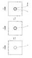
同図に示すように、ステージ(stage)201で、画像を取り込む。これによって、例えば図3の(a)に示すような画像が記憶部102に記憶され、かつ表示部104に表示される。画像はX線CT装置で撮影したファントム(phantom)の断層像である。断層像は中間調の画像となる。 As shown in the figure, an image is captured at a
ファントムはMTF測定用のファントムであり、中心部に円形断面のピン(pin)を有する。このため、断層像にはピンの断面を示す像2が含まれる。ピンの断面を示す像2の輪郭は円形となる。ピンの断面を示す像2の直径に沿った画素値プロファイル(profile)はLSFを表す。ピンの断面を示す像2は本発明におけるLSF像の実施の形態の一例である。以下、ピンの断面を示す像をピン像ともいう。 The phantom is a phantom for MTF measurement, and has a pin having a circular cross section at the center. For this reason, the tomographic image includes an
次に、ステージ203で、この断層像について、ピン像2を含む部分画像を指定する。部分画像の指定は使用者の操作に基づいて行われる。これによって、例えば一点鎖線で囲まれた部分画像4が指定される。部分画像4はピン像2が概ね中央に位置するように指定される。 Next, the
次に、ステージ205で、部分画像4の拡大画像を作成する。これによって、例えば図3の(b)に示すような拡大画像が得られる。拡大画像は、使用者が観察可能なように、表示部104に表示するようにしてもよい。 Next, an enlarged image of the partial image 4 is created on the
拡大画像の作成は、部分画像4のマトリクスサイズ(matrix size)を拡大するとともに、新たに増えた画素位置に元画像の画素値から計算した画素値を補間することによって行われる。補間は例えば1次補間によって行われる。なお、1次補間に限らず2次以上の高次の補間であって良い。ただし、1次補間は計算が簡素なのでコンピュータにとって負担が少ない。 The enlarged image is created by enlarging the matrix size of the partial image 4 and interpolating the pixel value calculated from the pixel value of the original image at the newly increased pixel position. Interpolation is performed by, for example, linear interpolation. Note that the interpolation is not limited to the primary interpolation but may be a higher-order interpolation of the second or higher order. However, since the primary interpolation is simple in calculation, the burden on the computer is small.
次に、ステージ207で、拡大画像を2値化する。2値化は所定の閾値を用いて行われる。これによって、例えば図3の(c)に示すような2値画像が得られる。2値画像は、使用者が観察可能なように、表示部104に表示するようにしてもよい。その場合、閾値を可変とし、使用者による閾値調節によって2値画像を最適化するようにしてもよい。 Next, at
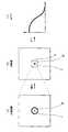
次に、ステージ209で、モルフォロジカル・オペレーション(morphological operation)を行う。モルフォロジカル・オペレーションは、数学的なモルフォロジイ(morphology)技法のひとつであり、画像処理の技術分野において既知である。 Next, at
モルフォロジカル・オペレーションとしてエロージョン/ダイレーション(erosion/dilation)が行われる。あるいは、それらに代えてオープニング/クロージング(opening/closing)を行うようにしてもよい。 Erosion / dilation is performed as a morphological operation. Alternatively, opening / closing (opening / closing) may be performed instead.
これらのオペレーションは、いずれも画像の微細構造部分や不規則構造部分を除去し、画像の基本構造を顕在化させる。このようなオペレーションを行うことにより、2値化されたピン像2の輪郭のノイズ等に由来する不規則性が除かれ、本来の円形輪郭がいっそう明確になる。 Each of these operations removes the fine structure portion and irregular structure portion of the image, and reveals the basic structure of the image. By performing such an operation, irregularity derived from noise or the like of the
図4の(a),(b)に、モルフォロジカル・オペレーションの前後のピン像2を概念的に示す。(a)がオペレーション前、(b)がオペレーション後である。明確化された輪郭を太線で表す。 4A and 4B conceptually show the
次に、ステージ211で、ピン像の輪郭座標を抽出し、この輪郭座標を用いて、ステージ213で、ハフ変換(Hough transform)により円の中心座標を求める。なお、ハフ変換は画像処理の技術分野における既知の技法である。 Next, the contour coordinates of the pin image are extracted at the
ハフ変換によって、(c)に示すように、ピン像2の中心20の座標が求まる。ピン像2の円形輪郭がモルフォロジカル・オペレーションにより明確化されているので、求められた中心座標は精度の良いものとなる。 By the Hough transform, the coordinates of the
次に、ステージ215で、中心座標を元画像における座標に変換する。座標変換は、図5の(a),(b)に示すように、拡大画像を元画像の部分画像4の大きさまで縮小することにより行われる。これによって、元画像において、ピン像2の中心20’の正確な座標が確定する。 Next, at
次に、ステージ217で、ピン像を2次元フーリエ変換してMTFを求める。2次元フーリエ変換は中心20’の座標を基準にして行われる。これによって、(c)に示すように、MTFが得られる。ピン像2の中心20’の座標が正確なのでMTFとして精度の良いものを得ることができる。 Next, at
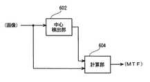
図6に、以上のような動作を行う本装置の機能ブロック図を示す。同図に示すように、本装置は中心検出部602および計算部604を有する。中心検出部602は、入力画像についてLSF像の中心の座標を検出して計算部604に入力する。計算部604は、入力された中心座標を基準として入力画像におけるLSF像を2次元フーリエ変換し、MTFを求める。 FIG. 6 shows a functional block diagram of the present apparatus that performs the above operation. As shown in the figure, this apparatus has a
中心検出部602は、上記のステージ201−215の動作を行うコンピュータ100の機能に相当する。中心検出部602は、本発明における検出手段の実施の形態の一例である。計算部604は、上記のステージ217の動作を行うコンピュータ100の機能に相当する。計算部604は、本発明における計算手段の実施の形態の一例である。 The
100 コンピュータ
102 記憶部
104 表示部
106 操作部
602 中心検出部
604 計算部100
Claims (8)
Translated fromJapanese前記中心を基準として前記LSF像を2次元フーリエ変換することによりMTFを求める方法であって、
前記中心の検出を、
前記断層像における前記LSF像を含む部分の拡大画像を作成し、
前記拡大画像を閾値に基づいて2値化し、
前記2値化された画像についてモルフォロジカル・オペレーションを行い、
前記オペレーション後の画像の輪郭座標を求め、
前記輪郭座標を用いてハフ変換により円の中心座標を求め、
前記中心座標を前記断層像における座標に変換する、
ことによって行う、
ことを特徴とするMTF測定方法。Detecting the center of the LSF image in the tomographic image obtained by imaging with an X-ray CT apparatus;
A method of obtaining an MTF by performing a two-dimensional Fourier transform on the LSF image with respect to the center,
The detection of the center,
Creating an enlarged image of a portion including the LSF image in the tomographic image;
Binarizing the enlarged image based on a threshold;
A morphological operation is performed on the binarized image,
Obtain the contour coordinates of the image after the operation,
Find the center coordinates of the circle by Hough transform using the contour coordinates,
Converting the central coordinates into coordinates in the tomographic image;
By doing,
The MTF measuring method characterized by the above-mentioned.
ことを特徴とする請求項1に記載のMTF測定方法。Creating the enlarged image by interpolation of pixel values;
The MTF measuring method according to claim 1.
ことを特徴とする請求項2に記載のMTF測定方法。The interpolation is a linear interpolation;
The MTF measuring method according to claim 2.
ことを特徴とする請求項1ないし請求項3のうちのいずれか1つに記載のMTF測定方法。The threshold is variable;
The MTF measurement method according to any one of claims 1 to 3, wherein
前記中心を基準として前記LSF像を2次元フーリエ変換することによりMTFを求める計算手段と、
を有するMTF測定装置であって、
前記検出手段は、
前記断層像における前記LSF像を含む部分の拡大画像を作成し、
前記拡大画像を閾値に基づいて2値化し、
前記2値化された画像についてモルフォロジカル・オペレーションを行い、
前記オペレーション後の画像の輪郭座標を求め、
前記輪郭座標を用いてハフ変換により円の中心座標を求め、
前記中心座標を前記断層像における座標に変換する、
ことによって前記中心を求める、
ことを特徴とするMTF測定装置。Detecting means for detecting the center of an LSF image in a tomographic image obtained by imaging with an X-ray CT apparatus;
A calculation means for obtaining an MTF by performing a two-dimensional Fourier transform on the LSF image with respect to the center;
An MTF measuring device having
The detection means includes
Creating an enlarged image of a portion including the LSF image in the tomographic image;
Binarizing the enlarged image based on a threshold;
A morphological operation is performed on the binarized image,
Obtain the contour coordinates of the image after the operation,
Find the center coordinates of the circle by Hough transform using the contour coordinates,
Converting the central coordinates into coordinates in the tomographic image;
Find the center by
The MTF measuring apparatus characterized by the above-mentioned.
ことを特徴とする請求項5に記載のMTF測定装置。The detecting means performs the creation of the enlarged image by interpolation of pixel values;
The MTF measuring apparatus according to claim 5.
ことを特徴とする請求項6に記載のMTF測定装置。The interpolation is a linear interpolation;
The MTF measuring apparatus according to claim 6.
ことを特徴とする請求項5ないし請求項7のうちのいずれか1つに記載のMTF測定装置。The threshold is variable;
The MTF measuring device according to claim 5, wherein the MTF measuring device is a device.
Applications Claiming Priority (1)
| Application Number | Priority Date | Filing Date | Title |
|---|---|---|---|
| CNB2003101196942ACN1306454C (en) | 2003-11-06 | 2003-11-06 | Modified transfer function measuring method and system |
Publications (2)
| Publication Number | Publication Date |
|---|---|
| JP2005137883A JP2005137883A (en) | 2005-06-02 |
| JP4102785B2true JP4102785B2 (en) | 2008-06-18 |
Family
ID=34529397
Family Applications (1)
| Application Number | Title | Priority Date | Filing Date |
|---|---|---|---|
| JP2004205729AExpired - LifetimeJP4102785B2 (en) | 2003-11-06 | 2004-07-13 | MTF measuring method and apparatus |
Country Status (4)
| Country | Link |
|---|---|
| US (1) | US7330609B2 (en) |
| JP (1) | JP4102785B2 (en) |
| CN (1) | CN1306454C (en) |
| DE (1) | DE102004053685A1 (en) |
Families Citing this family (17)
| Publication number | Priority date | Publication date | Assignee | Title |
|---|---|---|---|---|
| DE10161613A1 (en)* | 2001-12-15 | 2003-06-18 | Leica Microsystems | Self-monitoring scanning microscope has means for evaluating its image and providing precise guidance to an operator about actions to take to remove image defects |
| US8224017B2 (en)* | 2006-01-13 | 2012-07-17 | New Jersey Institute Of Technology | Method for identifying marked content |
| JP4463790B2 (en)* | 2006-08-07 | 2010-05-19 | アキュートロジック株式会社 | MTF measurement system, MTF measurement method, MTF measurement unit, and MTF measurement program |
| CN101452199B (en)* | 2007-11-30 | 2011-03-30 | 鸿富锦精密工业(深圳)有限公司 | Measurement method of modulation transfer function value |
| US20090268953A1 (en)* | 2008-04-24 | 2009-10-29 | Apteryx, Inc. | Method for the automatic adjustment of image parameter settings in an imaging system |
| CN101756709A (en)* | 2008-12-26 | 2010-06-30 | Ge医疗系统环球技术有限公司 | X-ray CT equipment |
| CN102204828B (en)* | 2011-05-13 | 2013-04-10 | 天津大学 | Method for accurately measuring modulation transfer function of digital X-ray imaging system |
| KR101767923B1 (en)* | 2012-05-11 | 2017-08-17 | 한화테크윈 주식회사 | Method and apparatus for inspecting via hole |
| CN103471811A (en)* | 2012-06-06 | 2013-12-25 | 上海西门子医疗器械有限公司 | Method for measuring detective quantum efficiency and system thereof |
| CN102809494A (en)* | 2012-07-10 | 2012-12-05 | 天津大学 | Knife-edge measuring method of modulation transfer function of digital X-ray imaging system |
| US10185303B2 (en)* | 2015-02-21 | 2019-01-22 | Kla-Tencor Corporation | Optimizing computational efficiency by multiple truncation of spatial harmonics |
| CN104933713B (en)* | 2015-06-12 | 2018-01-30 | 杭州电子科技大学 | A kind of image MTF methods of estimation using edge analysis |
| EP3410091B1 (en)* | 2017-06-02 | 2021-08-11 | Trioptics GmbH | Method for detecting a modulation transfer function and a centring system of an optical system |
| US11340136B2 (en) | 2017-06-02 | 2022-05-24 | Trioptics Gmbh | Apparatus for detecting a modulation transfer function and centering of an optical system |
| CN107219062A (en)* | 2017-06-20 | 2017-09-29 | 南京航空航天大学 | The frequency response measurement method and device of phase-modulator |
| DE202021103431U1 (en)* | 2021-06-28 | 2021-07-12 | Trioptics Gmbh | Device for imaging by an optical system to be tested and system for testing an optical system |
| CN115753024A (en)* | 2022-11-23 | 2023-03-07 | 江西联益光学有限公司 | Automatic centering method for lens MTF test |
Family Cites Families (16)
| Publication number | Priority date | Publication date | Assignee | Title |
|---|---|---|---|---|
| US4132654A (en) | 1976-07-02 | 1979-01-02 | The Machlett Laboratories, Inc. | X-ray focal spot test system |
| US4097793A (en) | 1976-10-22 | 1978-06-27 | The Machlett Laboratories, Inc. | X-ray testing system |
| US4239395A (en) | 1978-08-07 | 1980-12-16 | Modisette James E | Radiographic imaging system quality monitor |
| US4394737A (en)* | 1979-07-11 | 1983-07-19 | Fuji Photo Film Co., Ltd. | Method of processing radiographic image |
| US4331021A (en)* | 1980-09-11 | 1982-05-25 | The United States Of America As Represented By The Secretary Of The Department Of Health And Human Services | Contrast resolution tissue equivalent ultrasound test object |
| NL9001265A (en)* | 1990-06-05 | 1992-01-02 | Philips Nv | METHOD FOR DETERMINING A MODULATION TRANSFER FUNCTION OF A DIGITAL IMAGING SYSTEM. |
| US5657400A (en)* | 1995-01-31 | 1997-08-12 | General Electric Company | Automatic identification and correction of bad pixels in a large area solid state x-ray detector |
| ES2205019T3 (en)* | 1995-03-03 | 2004-05-01 | Northrop Grumman Corporation | MEASUREMENT OF THE MODULATION TRANSFER FUNCTION. |
| KR100271904B1 (en) | 1995-11-28 | 2001-01-15 | 토비 에취. 쿠스머 | Pre-calibration device and method of X-ray tube focus |
| US5760403A (en)* | 1996-04-18 | 1998-06-02 | Loral Fairchild Corp. | High modulation transfer function CCD X-ray image sensor apparatus and method |
| US6233349B1 (en)* | 1997-06-20 | 2001-05-15 | General Electric Company | Apparata and methods of analyzing the focal spots of X-ray tubes |
| US5959726A (en)* | 1997-07-25 | 1999-09-28 | Neopath, Inc. | Modulation transfer function test compensation for test pattern duty cycle |
| DE19852324C2 (en) | 1998-11-12 | 2000-11-16 | Siemens Ag | Phantom for measuring layer sensitivity profiles and the axial modulation transfer function (MTF) on an X-ray computer tomograph |
| US6694047B1 (en)* | 1999-07-15 | 2004-02-17 | General Electric Company | Method and apparatus for automated image quality evaluation of X-ray systems using any of multiple phantoms |
| US6895077B2 (en)* | 2001-11-21 | 2005-05-17 | University Of Massachusetts Medical Center | System and method for x-ray fluoroscopic imaging |
| CN1202490C (en)* | 2003-03-19 | 2005-05-18 | 上海交通大学 | Iris marking normalization process method |
- 2003
- 2003-11-06CNCNB2003101196942Apatent/CN1306454C/ennot_activeExpired - Fee Related
- 2004
- 2004-07-13JPJP2004205729Apatent/JP4102785B2/ennot_activeExpired - Lifetime
- 2004-11-03DEDE102004053685Apatent/DE102004053685A1/ennot_activeCeased
- 2004-11-04USUS10/981,916patent/US7330609B2/enactiveActive
Also Published As
| Publication number | Publication date |
|---|---|
| CN1306454C (en) | 2007-03-21 |
| CN1614632A (en) | 2005-05-11 |
| JP2005137883A (en) | 2005-06-02 |
| US20050100244A1 (en) | 2005-05-12 |
| US7330609B2 (en) | 2008-02-12 |
| DE102004053685A1 (en) | 2005-06-09 |
Similar Documents
| Publication | Publication Date | Title |
|---|---|---|
| JP4102785B2 (en) | MTF measuring method and apparatus | |
| JP4711662B2 (en) | Iterative CT reconstruction method using multimode edge information | |
| JP5819428B2 (en) | Image diagnostic apparatus and image correction method | |
| JP5613501B2 (en) | Pipe thickness measuring apparatus and method | |
| KR102021945B1 (en) | Determination of localised quality measurements from a volumetric image record | |
| JP5210615B2 (en) | Medical image diagnosis support apparatus and medical image diagnosis support program | |
| US11593941B2 (en) | Image processing apparatus, image processing method, and storage medium | |
| JP2014203162A (en) | Inclination angle estimation device, mtf measuring apparatus, inclination angle estimation program and mtf measurement program | |
| JP5976126B2 (en) | System and method for estimating target size | |
| US7433086B2 (en) | Edge detection and correcting system and method | |
| JP2024522311A (en) | Systems, methods and devices for identifying heterogeneous liver fat | |
| EP3038050A1 (en) | Method and device for restoring scan image and recording medium for storing same | |
| JP2005528965A (en) | Multidimensional structure analysis method | |
| TWI500412B (en) | A method for improving image quality and imaging system using the same | |
| JP4549082B2 (en) | Image processing apparatus and method | |
| US20140254903A1 (en) | Estimation of confidence limits for measurements derived from image data | |
| CN116091522A (en) | Medical image segmentation method, device, equipment and readable storage medium | |
| JP2003135450A (en) | Method for reducing artifacts in x-ray ct reconstructed image | |
| JP2006185038A (en) | Four- or n-dimensional labeling apparatus, and four- or n-dimensional spatial filter apparatus | |
| US10810713B2 (en) | Image processing device and image processing method | |
| JP2006334319A (en) | X-ray CT apparatus and preprocessing method thereof, data creation apparatus and method thereof, and control program | |
| JPH06327647A (en) | MRI slice plane automatic determination method and flow velocity measurement method based on this method | |
| JPH05237094A (en) | Image processing method and apparatus for reducing streak-like false image | |
| CN118628648B (en) | A three-dimensional reconstruction method, device, electronic device and storage medium | |
| JPH0778841B2 (en) | Track displacement measuring method and track displacement measuring device |
Legal Events
| Date | Code | Title | Description |
|---|---|---|---|
| A625 | Written request for application examination (by other person) | Free format text:JAPANESE INTERMEDIATE CODE: A625 Effective date:20050323 | |
| A977 | Report on retrieval | Free format text:JAPANESE INTERMEDIATE CODE: A971007 Effective date:20071130 | |
| TRDD | Decision of grant or rejection written | ||
| A01 | Written decision to grant a patent or to grant a registration (utility model) | Free format text:JAPANESE INTERMEDIATE CODE: A01 Effective date:20080318 | |
| A61 | First payment of annual fees (during grant procedure) | Free format text:JAPANESE INTERMEDIATE CODE: A61 Effective date:20080324 | |
| FPAY | Renewal fee payment (event date is renewal date of database) | Free format text:PAYMENT UNTIL: 20110328 Year of fee payment:3 | |
| R150 | Certificate of patent or registration of utility model | Ref document number:4102785 Country of ref document:JP Free format text:JAPANESE INTERMEDIATE CODE: R150 Free format text:JAPANESE INTERMEDIATE CODE: R150 | |
| FPAY | Renewal fee payment (event date is renewal date of database) | Free format text:PAYMENT UNTIL: 20110328 Year of fee payment:3 | |
| FPAY | Renewal fee payment (event date is renewal date of database) | Free format text:PAYMENT UNTIL: 20110328 Year of fee payment:3 | |
| FPAY | Renewal fee payment (event date is renewal date of database) | Free format text:PAYMENT UNTIL: 20120328 Year of fee payment:4 | |
| R250 | Receipt of annual fees | Free format text:JAPANESE INTERMEDIATE CODE: R250 | |
| FPAY | Renewal fee payment (event date is renewal date of database) | Free format text:PAYMENT UNTIL: 20120328 Year of fee payment:4 | |
| FPAY | Renewal fee payment (event date is renewal date of database) | Free format text:PAYMENT UNTIL: 20130328 Year of fee payment:5 | |
| R250 | Receipt of annual fees | Free format text:JAPANESE INTERMEDIATE CODE: R250 | |
| FPAY | Renewal fee payment (event date is renewal date of database) | Free format text:PAYMENT UNTIL: 20130328 Year of fee payment:5 | |
| FPAY | Renewal fee payment (event date is renewal date of database) | Free format text:PAYMENT UNTIL: 20130328 Year of fee payment:5 | |
| FPAY | Renewal fee payment (event date is renewal date of database) | Free format text:PAYMENT UNTIL: 20140328 Year of fee payment:6 | |
| R250 | Receipt of annual fees | Free format text:JAPANESE INTERMEDIATE CODE: R250 | |
| R250 | Receipt of annual fees | Free format text:JAPANESE INTERMEDIATE CODE: R250 | |
| R250 | Receipt of annual fees | Free format text:JAPANESE INTERMEDIATE CODE: R250 | |
| R250 | Receipt of annual fees | Free format text:JAPANESE INTERMEDIATE CODE: R250 | |
| R250 | Receipt of annual fees | Free format text:JAPANESE INTERMEDIATE CODE: R250 | |
| R250 | Receipt of annual fees | Free format text:JAPANESE INTERMEDIATE CODE: R250 | |
| R250 | Receipt of annual fees | Free format text:JAPANESE INTERMEDIATE CODE: R250 | |
| R250 | Receipt of annual fees | Free format text:JAPANESE INTERMEDIATE CODE: R250 |