JP4102409B2 - Suture and ligature applier - Google Patents
Suture and ligature applierDownload PDFInfo
- Publication number
- JP4102409B2 JP4102409B2JP2006102022AJP2006102022AJP4102409B2JP 4102409 B2JP4102409 B2JP 4102409B2JP 2006102022 AJP2006102022 AJP 2006102022AJP 2006102022 AJP2006102022 AJP 2006102022AJP 4102409 B2JP4102409 B2JP 4102409B2
- Authority
- JP
- Japan
- Prior art keywords
- suturing
- ligating
- tool
- proximal end
- legs
- Prior art date
- Legal status (The legal status is an assumption and is not a legal conclusion. Google has not performed a legal analysis and makes no representation as to the accuracy of the status listed.)
- Expired - Fee Related
Links
Images


Landscapes
- Surgical Instruments (AREA)
Description
Translated fromJapaneseこの発明は、主に外科手術に使用され、生体組織を縫合・結紮等をするための縫合・結紮具アプライヤーに関する。 The present invention relates to a suturing / ligating applier for use in surgical operations and for suturing / ligating biological tissue.
従来、生体組織の縫合・結紮は針糸あるいは金属や樹脂製のクリップ・ステープルによって行われていた。これらのうち金属製のクリップ・ステープルは、血管等の脈管を結紮する場合には特許文献1,2に示すような形状のクリップを使用し、組織を縫合する場合には特許文献3に示すような形状のステープルを使用していた。 Conventionally, suture and ligation of living tissue has been performed with a needle thread or a clip or staple made of metal or resin. Among these, metal clips and staples use a clip having a shape as shown in
また、現在のクリップの場合、特許文献4、5に示すような連発式のものが一般的である。縫合・結紮具の変形がし易いように、特許文献6のように基端部の厚みを薄くしたものも知られている。
これらの従来技術において、血管等の脈管を結紮するためのクリップは特許文献2,4のように、クリップの脚の部分を外周からジョーによって圧縮変形することによって取り付けられていたが、脚の部分を外周から圧縮するというクリップの変形の方法のために、どうしてもアプライヤーの構造が複雑にならざるを得なかった。 In these prior arts, a clip for ligating a blood vessel or the like was attached by compressing and deforming the leg portion of the clip from the outer periphery with a jaw as in
さらに、アプライヤーの構造が複雑なために特に内視鏡下外科手術において使用する場合、その挿入径を細くすることが難しく、一般的にはφ10mm以上の径となってしまい、その他の処置具の挿入径がφ5mm程度なのに対して倍の太さとなっており、その倍の太さの孔を人体に開けるために低侵襲という内視鏡下外科手術のメリットを損なっていた。また、その変形方法がジョーによって挟むような動作となるため、万一クリップが装填されなかった場合等に、ジョーによって直接脈管を把持して損傷してしまうこともあった。 Furthermore, since the structure of the applier is complicated, it is difficult to reduce the insertion diameter, particularly when used in endoscopic surgery, and generally the diameter is 10 mm or more. The insertion diameter is twice as large as that of φ5 mm, and the advantage of endoscopic surgery, which is minimally invasive, is incurred in order to open a hole of that double thickness in the human body. Further, since the deformation method is an operation to be sandwiched between the jaws, the vascular vessel may be directly gripped and damaged by the jaws in the event that a clip is not loaded.
また、特許文献3の場合には、その構造はクリップに比べて簡単であり、万一ステープルが装填されなかった場合にも、その動作によって組織を損傷する危険性は少ないが、そのステープルの形状のために組織の縫合はできても脈管の結紮をすることはできなかった。 Further, in the case of
また、従来、血管等の脈管を結紮する場合には特許文献1や特許文献2のような形状の金属製クリップが用いられており、現在では特許文献5のような連発式アプリケーターのものが用いられている。 Conventionally, when a vessel such as a blood vessel is ligated, a metal clip having a shape as in Patent Document 1 or
これらのクリップはその2本の脚部の脚間距離が結紮する目的の脈管の直径以上必要で、その脚部の長さも目的の脈管の直径以上の距離を有している必要があった。また、その2本の脚部を連結している基端部はクリップを変形させやすくするための略三角形状となっていたが、それによってクリップ全長が結紮のための必要な長さ以上に長くなっており、不必要に大きな残留物を生体内に留めることとなっていた。 These clips need to have a distance between the legs of the two legs that is greater than the diameter of the intended vessel to be ligated, and the length of the legs must also be greater than the diameter of the intended vessel. It was. In addition, the base end portion connecting the two leg portions has a substantially triangular shape for facilitating deformation of the clip, so that the entire length of the clip is longer than the length necessary for ligation. Therefore, an unnecessarily large residue is to be kept in the living body.
さらに、一般的にクリップは、特許文献4のようにアプライヤーの操作部とジョーの間に順列状態で貯蔵されているが、クリップの長さが長いために貯蔵できるクリップの数は大体20個以下となっており、それ以上にクリップを貯蔵することができなかった。 Further, generally, the clips are stored in a permutation state between the operation portion of the applier and the jaw as in
さらに、特許文献3のようなステープルの場合、基端部を後方から押圧することによって変形させていたが、その変形方法のために変形させる際に強い力量が必要であり、そのためにアプライヤー本体の操作手段において操作手段を操作する力量の数倍の力量を発生させる必要があった。この際にモーメントの関係によって操作手段を操作するストロークが、操作力量に対して作動力量を増大させればさせる程、増加することは避けられないために、その操作ストロークが大きくなりがちであった。 Further, in the case of the staple as in
また、特許文献1,2,4のようなクリップの場合には、前述のようにその変形に必要な力量を低減させるためにクリップの基端部を略三角形状としていたため、クリップの大きさが不必要に大きくなっており、生体内部に不必要に大きな残留物を残す、あるいはアプライヤー内部に数多くのクリップを貯蔵できないという問題点があった。 In addition, in the case of a clip as in
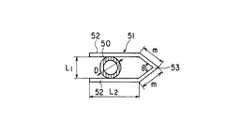
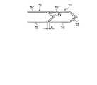
すなわち、図28および図29に示すように、従来の縫合・結紮具51は生体内に留置される関係上、生体に対して毒性等が無くMRIのアンチアーキファクト性を確保するTi合金等のチタン材で製造されている。一般に直径Dの脈管50を結紮するためには脚部52の長さが約2倍程度必要である。また、当然前記2本の脚部52間距離L1 はL1 ≧Dとなっていなくてはならない。ここで従来技術の場合には縫合・結紮具51を変形させやすくするために、基端部53が角度θの略三角形状となっている。そのために全長はL2 +mcosθとなっている。 That is, as shown in FIG. 28 and FIG. 29, the conventional suturing / ligating
そして、アプライヤーに順列状態に貯蔵した場合、図29に示すように、縫合・結紮具51の2つにつきnだけの無駄な長さが必要となり、縫合・結紮具51の数が多くなればなる程その長さは増大し、結果として貯蔵部に貯蔵できる縫合・結紮具51の数が減少してしまう。最近行われているアドバンス手技と呼ばれる先進的な内視鏡下外科手術において、従来のアプライヤーに貯蔵されている20個の縫合・結紮具51よりも多くの縫合・結紮具51を必要とするが、30個程度必要とされることは少ない。 When the appliers are stored in a permuted state, as shown in FIG. 29, a wasteful length of n is required for each of the two stitching /
ところが、前述のように従来技術では一般に20個しか貯蔵できないので、このような場合には2本のアプライヤーを使用することになる。しかし、アプライヤーは一般にディスポーザブルなので2本目のアプライヤーの残りの10個以上の縫合・結紮具51は無駄となってしまう。 However, as described above, the prior art can generally store only 20 pieces, and in such a case, two appliers are used. However, since the applier is generally disposable, the remaining ten or more suture /
このような状況に対して、特許文献5のように基端部の厚みを薄くすることによって変形しやすくしているものもあったが、この場合、基端部の幅が広くなっているので、それを貯蔵しているアプライヤーが太くなってしまうという問題もあった。 For such a situation, there are some which are easily deformed by reducing the thickness of the base end portion as in
さらに、従来のクリップあるいはステープルの2本の脚部の近接する部分には特にお互いを係合させるような構造がないため、実際に組織を縫合・結紮した際に2本の脚部が互いに対向して近接せずにずれてしまうこともあり、そのような場合には確実な縫合・結紮に支障をきたすこともあった。 Furthermore, since the adjacent portions of the two legs of the conventional clip or staple are not particularly structured to engage each other, the two legs face each other when the tissue is actually sutured or ligated. In such a case, there is a case where reliable suturing / ligating is hindered.
前記クリップあるいはステープルでは取付手段とクリップあるいはステープルの係合手段が設けられていないため、生体組織にクリップあるいはステープルを取り付ける際に、取り付けが完了する前に脱落してしまったり、取り付けの最中に外乱によってクリップあるいはステープラーの向きが変化してしまう恐れがあった。 Since the clip or staple is not provided with attachment means and clip or staple engagement means, when the clip or staple is attached to the living tissue, it may fall off before the attachment is completed, or during the attachment. The direction of the clip or stapler may change due to disturbance.
さらに、前記クリップあるいはステープルで生体組織を縫合・結紮する際に、取り付けた後にクリップあるいはステープルが生体組織から滑って脱落してしまうことがあり、その防止のためにクリップあるいはステープルに滑り止めを設ける必要があった。 Furthermore, when a biological tissue is sutured or ligated with the clip or staple, the clip or staple may slip off from the biological tissue after being attached, and the clip or staple is provided with a non-slip to prevent this. There was a need.
この発明は、前記事情に着目してなされたもので、その目的とするところは、生体組織をより確実に縫合・結紮できる縫合・結紮具アプライヤーを提供することにある。 The present invention has been made paying attention to the above circumstances, and an object of the present invention is to provide a suture / ligator applier that can suture and ligate a living tissue more reliably.
この発明は、前記目的を達成するために、請求項1は、先端と基端とを有する細長の2本の脚部とこの2本の脚部の間に生体組織を挿入可能にこの脚部の基端と連結する基端部とを有し、前記2本の脚部は略平行状態で、これら脚部と前記基端部とによって囲まれた空間を有し、さらに前記基端部に他の部分より折れ曲りやすい折れ曲り部を有する縫合・結紮具を用い、生体組織を縫合結紮する縫合・結紮具アプライヤーであって、
先端と基端とを有する細長の挿入部と、前記挿入部の先端側に設けられ、前記縫合・結紮具の前記空間内に位置し、前記基端部の長手方向の中間部を支持する支持部材と、前記挿入部に対して前後方向に移動可能に設けられ、先端部に前記縫合・結紮具の基端部の中間部を避け、両端側を前記挿入部の先端方向に押圧して前記縫合・結紮具を塑性変形させる2箇所の押圧部を有する押圧手段と、前記挿入部の基端に設けられ、前記挿入部に対して前記押圧手段を移動させる操作手段とを備え、前記支持部材は、前記縫合・結紮具の基端部における長手方向の中間部を支持し、前記押圧手段は、前記操作手段の操作により前記挿入部の先端方向に移動することにより、前記縫合・結紮具の基端部における長手方向の両端部を前記2箇所の押圧部で同時に押圧して前記縫合・結紮具の前記折り曲げ部を折り曲げ、前記2本の脚部の先端同士を接触させた後、前記2本の脚部同士を略平行に近接させることを特徴とする。In order to achieve the above-mentioned object, according to the present invention, there is provided an elongated leg portion having a distal end and a proximal end, and the leg portion so that a living tissue can be inserted between the two leg portions. A base end connected to the base end, the two legs are in a substantially parallel state, and have a space surrounded by the legs and the base end, and the base end A suture / ligator applier that uses a suture / ligator having a bent portion that is easier to bend than other parts, and sutures and ligates biological tissue,
An elongated insertion portion having a distal end and a proximal end, and a support provided on the distal end side of the insertion portion and positioned in the space of the suturing / ligating tool and supporting a longitudinal intermediate portion of the proximal end portion A member and a movable portion in the front-rear direction with respect to the insertion portion,avoiding anintermediate portion of the proximal end portion of the suturing / ligating tool at the distal end portion, and pressing both ends in the distal end direction of the insertion portionA pressing meanshaving two pressing portions for plastically deforming the stitching / ligating tool; and an operating means provided at a proximal end of the insertion portion to move the pressing means relative to the insertion portion; Supports the intermediate portion in the longitudinal direction at the proximal end portion of the suturing / ligating tool, and the pressing means moves in the distal direction of the insertion portion by operation of the operating means, therebypressing part of the longitudinal end portions ofthe two positions at the proximal endAt the same time pressed by bending the bent portion of the suturing-ligation tool,after contacting the tips of the two legs, and characterized inthat substantially parallel to close the leg portions of the two.
請求項2は、請求項1の前記2本の脚部に他の部分より折れ曲りやすい折り曲げ部を有し、前記2箇所の押圧部の押圧に伴って前記基端部の折り曲げ部が折り曲げられ、前記2本の脚部の先端同士を接触した後、前記2本の脚部の折り曲げ部が前記基端部の折り曲げ部と逆方向に折り曲げられることを特徴とする。According to a second aspect of the present invention, the two leg portions of the first aspect have a bent portion that is easier to bend than other portions, and the bent portion of the base end portion is bent along withthe pressing of the two pressing portions.After the tips of the two leg portions are brought into contact with each other, the bent portions of the two leg portions are bent in thedirection opposite to the bent portion of the base end portion .
請求項3は、先端と基端とを有する細長の2本の脚部とこの2本の脚部の間に生体組織を挿入可能にこの脚部の基端と連結する基端部とを有し、前記2本の脚部は略平行状態で、これら脚部と前記基端部とによって囲まれた空間を有し、さらに前記脚部に他の部分より折れ曲りやすい折れ曲り部を有する縫合・結紮具を用い、生体組織を縫合結紮する縫合・結紮具アプライヤーであって、
先端と基端とを有する細長の挿入部と、前記挿入部の先端側に設けられ、前記縫合・結紮具の前記空間内に位置し、前記基端部の長手方向の中間部を支持する支持部材と、前記挿入部に対して前後方向に移動可能に設けられ、先端部に前記縫合・結紮具の基端部の両端側を前記挿入部の先端方向に押圧して前記縫合・結紮具を塑性変形させる押圧手段と、前記挿入部の基端に設けられ、前記挿入部に対して前記押圧手段を移動させる操作手段とを備え、前記支持部材は、前記縫合・結紮具の基端部における長手方向の中間部を支持し、前記押圧手段は、前記操作手段の操作により前記挿入部の先端方向に移動することにより、前記縫合・結紮具の基端部における長手方向の両端部を前記2箇所の押圧部で同時に押圧し、該基端部を折り曲げて前記2本の脚部の先端同士を接触させた後、前記2本の脚部の折り曲げ部を折り曲げ、前記2本の脚部同士を略平行に近接させることを特徴とする。The third aspect of the present invention has two elongated legs having a distal end and a proximal end, and a proximal end connected to the proximal end of the leg so that a living tissue can be inserted between the two legs. The two leg portions are substantially parallel, have a space surrounded by the leg portions and the base end portion, and further have a bent portion in the leg portion that is easier to bend than other portions. A suturing / ligating applier that uses a ligation tool to sew and ligate living tissue,
An elongated insertion portion having a distal end and a proximal end, and a support provided on the distal end side of the insertion portion and positioned in the space of the suturing / ligating tool and supporting a longitudinal intermediate portion of the proximal end portion A member and movably provided in the front-rear direction with respect to the insertion portion, and by pressing both ends of the proximal end portion of the suturing / ligating tool toward the distal end of the inserting portion, A pressing means for plastic deformation; and an operating means for moving the pressing means relative to the insertion portion provided at a proximal end of the insertion portion, wherein the support member is provided at a proximal end portion of the suturing / ligating tool. supporting the middle portion in the longitudinal direction, said pressing means is moved in a distal direction of the insertion portion by operating the operation means,wherein the both ends in the longitudinal direction at the proximal end of the suture-
この発明の縫合・結紮具アプライヤーによれば、先端と基端とを有する細長の2つの脚部とこの2つの脚部の基端と連結する基端部とを有する略コ字状の縫合・結紮具を、この脚部の先端同士から閉じるため、2つの脚部に挿入した生体組織がより外れにくくなり、より確実に生体組織を縫合・結紮することができるという効果がある。 According to the suture / ligator applier of the present invention, a substantially U-shaped suture having two elongated legs having a distal end and a proximal end and a proximal end connected to the proximal ends of the two legs. -Since the ligature is closed from the tips of the legs, the biological tissues inserted into the two legs are less likely to come off, and the biological tissues can be sutured and ligated more reliably.
以下、この発明の各実施の形態を図面に基づいて説明する。 Embodiments of the present invention will be described below with reference to the drawings.
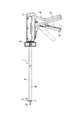
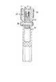
図1〜図22は第1の実施形態を示す。図1は後述するクリップあるいはステープルである縫合・結紮具を生体組織に取り付けるアプライヤー1を示し、このアプライヤー1は、縫合・結紮具を変形させる取り付け手段2と、取り付け手段2を図示しないトラカール等を介して生体組織に挿入するための内視鏡手段である挿入部3と、取り付け手段2の操作を行う操作手段4から構成されている。また、操作手段4に対して挿入部3が回動自在となっており、その回動操作を行うためのノブ5が挿入部3の手元側の操作手段4との接合部に設けられている。 1 to 22 show a first embodiment. FIG. 1 shows an applier 1 for attaching a suturing / ligating tool, which will be described later, to a living tissue. The applier 1 has an attaching
前記挿入部3は、図2に示すように、上下に分割された略透明な上部挿入部材6と下部挿入部材7によって構成され、両者を組み合わせた後に外套管8を被覆することにより組立られている。この外套管8は透明な熱収縮チューブによって形成され、挿入部3の内部が確認できるようになっている。 As shown in FIG. 2, the
前記操作手段4は、図1に示すように、可動ハンドル9と固定ハンドル10からなっており、可動ハンドル9を固定ハンドル10に対して回動させることにより、取り付け手段2の操作を行うことができる。 As shown in FIG. 1, the operation means 4 includes a
また、操作手段4の固定ハンドル10における上部には後述するように蓋体11が取り付けられ、この蓋体11を開閉することにより、挿入部3を操作手段4に着脱したり、操作手段4の内部を洗浄・滅菌することができるようになっている。 Further, a lid body 11 is attached to the upper portion of the fixed
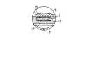
次に、前記取り付け手段2の構成について図2〜図6に示す。取り付け手段2は先端に縫合・結紮具12を取り付け時のガイドとなるガイド部材13を有し、この内部に縫合・結紮具12が装填されている。この縫合・結紮具12を装填し、生体組織に取り付ける操作は後述するようにプッシャー14によって行われる。 Next, the structure of the attachment means 2 is shown in FIGS. The attachment means 2 has a
ガイド部材13には縫合・結紮具12の取り付け時に縫合・結紮具12を支持する支持部材、例えば支持ピン15が設けられており、これにより縫合・結紮具12は前方へ脱落せずに支持される。従来技術ではガイド部材13が無く、縫合・結紮具12を確実に保持できないために、支持ピン15を間隔をおいて2本設けていたので、縫合・結紮具12の脚部12a間距離が脚部12aの全長に対して比較的広くなっていたが、本実施形態では、押圧手段を構成する第1の押圧部としての支持ピン15を1個であるので脚部12a間距離を比較的狭くすることができ、脈管の結紮に非常に有効であるばかりか、ガイド部材13の外形や挿入部3の外径を小さくできるので、低侵襲という観点において効果がある。The
一般的に縫合・結紮具12を生体組織に取り付けるアプライヤー1の挿入部3の外径はφ10〜12mmであるが、本実施形態の場合には前述のようなシンプルな構造によって、使用する縫合・結紮具12を収納するのに必要な幅である7mmを確保すれば良いので、さらに上部挿入部材6と下部挿入部材7の肉厚をそれぞれ0.5mmずつ確保して、挿入部3外径でφ8mmを達成している。また、従来技術では前記支持ピン15は取り付け手段2の先端から突出しており、生体組織に損傷を与える危険性も無視できなかったが、本実施形態ではガイド部材13の内部に格納されているので、生体組織に触れる恐れもない。 In general, the outer diameter of the
また、前記ガイド部材13は支持ピン15が設けられている部分以外はそれ程の強度が必要ないので、ガイド部材13を少なくとも部分的に透明として縫合・結紮動作が目視しやすくしても良く、それにより安全・確実な縫合・結紮に寄与するので、アプライヤー1の安全性が向上する。 Further, since the
そして、第1の押圧部としての支持ピン15とにより、縫合・結紮具12を生体組織に取り付ける際に縫合・結紮具12を所定の形状に変形させるために、第2の押圧部としてのプッシャー14には凹状部16が設けられている。そして、支持ピン15とプッシャー14とによって押圧手段を構成している。そして、押圧手段によって縫合・結紮具12を生体組織に取り付けた後に、アプライヤー1から放出するためのイジェクター17がガイド部材13の内部の縫合・結紮具12の下部に取り付けられている。 The pusher as the second pressing portion is used to deform the suturing / ligating
ガイド部材13は挿入部3を構成している下部挿入部材7にピン17aで固定されており、下部挿入部材7の上部には仕切板18が取り付けられ、その上に縫合・結紮具12を貯蔵しておくための貯蔵手段19が設けられており、その上部に上部挿入部材6には縫合・結紮具12を下方へ抑える抑えスプリング22が取り付けられている。そして、さらに全体を前記外套管8で覆っている。これらの挿入部3を構成している部材のうち、外套管8、上部挿入部材6、下部挿入部材7は前述のように樹脂材で透明に成型されており、取り付け手段2と貯蔵手段19の状態が目視できるようになっている。 The
前記プッシャー14には貯蔵手段19の最前列の縫合・結紮具12を送り出すための移送手段である掛止部20が設けられている。そして、貯蔵手段19には縫合・結紮具12が後方へ逆戻りしないようにワンウェイクラッチ21が設けられている。そして、アプライヤー1には先端部から後端部に向かって複数、例えば20個の縫合・結紮具12a〜12tが収納されているが、初期状態において収納されている縫合・結紮具12の個数は特に限定されず、目的の手技に応じて幾つでも構わない。 The
また、後述するように本実施形態では従来技術に対して同じ個数の縫合・結紮具12ならば、その縫合・結紮具12列全体の長さを短くできるので、同一の長さの貯蔵手段19の内部に従来技術よりもさらに多くの縫合・結紮具12を貯蔵できる。 In addition, as will be described later, in the present embodiment, if the same number of stitching /
次に、前記挿入部3の略中間部から手元側の構成を図7〜図9に示す。貯蔵手段19の後部の最後部の縫合・結紮具12tにおける後部には縫合・結紮具12列を前方に付勢するためのプレート状のバッファー23が係合しており、このバッファー23はクリップ押しスプリング24によって前方に付勢されている。そして、クリップ押しスプリング24の後部はスプリングホルダー25によって挿入部3の手元側に固定されている。バッファー23は蛍光色等の目視しやすい色調に成型され、このバッファー23が縫合・結紮具12が放出される度に前方に移動することで、縫合・結紮具12の残量が判るようになっている。 Next, FIG. 7 to FIG. 9 show the configuration of the
また、この色調を任意に設定することにより、貯蔵されている縫合・結紮具12の数や種類等を表示するようにしても良い。あるいは、挿入部3を構成している各部品の色調を任意に設定することによって、表示しても構わない。そのような場合には例えばガイド部材13の色が青ならば縫合・結紮具の個数が20個で、赤ならば10個である等とすることができる。勿論、2種類以上の色を使用してその組み合わせによって表示しても構わない。一般に手術室では使用する機材の選択は術者の指示によって助手が行うが、助手は機材に記入されている文字等を読んで目的の機材かどうか判断するのでは無く、その形状や色等の外観ですぐに判断できる要素で判断するため、このような色識別は誤った機材選定を防止することや手技の効率化にもつながるために非常に有効である。 Further, by arbitrarily setting the color tone, the number, type, and the like of the stored sewing /
前記プッシャー14にはラチェットアーム26が取り付けられており、下部挿入部材7に取り付けられたラチェット歯27とによりラチェット機構28を形成しており、プッシャー14が動作の途中で戻ることによって縫合・結紮具12が取り付け手段2の内部で詰まったりすることを防止している。また、従来のようなラチェット機構ではラチェット歯27に噛み合う相手方の部品は専用の薄刃形状の部品を使用するのが一般的であるが、必要な弾性力を出したりするためにコストが嵩む部品であった。しかし、本実施形態ではラチェットアーム26は丸棒を折り曲げた構造のものであり、弾性力を出すことはその有効長を長くすることで対応しているので、コストも掛からずに簡単に成型できる部品となっている。 A
次に、図10に挿入部3の手元側を示す。挿入部3の後端にはノブ5が設けられており、上下に分割された部品により構成されている。このノブ5の内部にはメインスプリング29が設けられており、プッシャー14に接続された操作棒30を常時手元側に付勢している。そして、このメインスプリング29により、一連のクリップ取り付け操作終了後に取り付け手段2と操作手段4を含めたアプライヤー1全体を初期状態に復帰させることができる。 Next, FIG. 10 shows the proximal side of the
この操作棒30の後部は可動ハンドル9の上部に設けられている係合溝31と係合する球状部32が形成されており、操作棒30とノブ5の後部はOリング33によってシールされている。一般に内視鏡的治療においては腹腔内等において操作する空間を確保するために、気腹と呼ばれる腹腔をCO2 ガスによって膨らませた状況において治療を行う。その際に用いられるこのアプライヤー1のような処置具は、腹腔内のガスが外部に漏れないようになっている必要があるが、このアプライヤー1は前記Oリング33によって、完全にその内部が密封されているか、あるいは実用上差し支え無い程度のガス漏れに抑えられている。 A
また、前述のようにプッシャー14とそれに接続される操作棒30は挿入部3の長手方向の挿入軸中心に設けられているので、前記ノブ5を操作することによって挿入部3を操作手段4に対して回動させる際に、その回動中心に位置するため、従来技術のように回動に対応するための、プッシャー14と操作棒30を連結する特別な変換手段を使用しなくても回動可能なようになっている。 Further, as described above, the
次に、図11〜図14に操作手段4を示す。操作手段4は、前述したように、可動ハンドル9と固定ハンドル10、固定ハンドル10の上部に取り付けられた蓋体11からなっている。固定ハンドル10には前記挿入部3のノブ5が回動自在に取り付けられており、操作棒30の球状部32は可動ハンドル9の上部に設けられた係合溝31の内部の座金34に摺動・回動自在に係合している。 Next, the operation means 4 is shown in FIGS. As described above, the operation means 4 includes the
そして、蓋体11は固定ハンドル10に対してヒンジ35によって開閉自在に取り付けられており、閉鎖時の固定はスナップフィット36によって行われる。また、蓋体11を開放させる際にはこのスナップフィット36に取り付けられている摘み37を外側に付勢することにより、スナップフィット36と固定ハンドル10の係合を解除してヒンジ35により開放する。 The lid 11 is attached to the fixed
操作手段4の固定ハンドル10の内部は洗浄・滅菌のために洗浄液や滅菌ガスあるいは高温蒸気や、洗浄ブラシ等の洗浄具が挿通できるように空間が開いており、その上部は前述のように蓋体11を開放することにより、確実に洗浄・滅菌可能となっており、操作手段4は繰り返し使用できるリユース製品となっている。また、操作手段4を構成する各部品は耐洗浄・滅菌性を有する金属あるいは樹脂により構成されているのは言うまでもない。 The interior of the fixed
また、操作棒30の球状部32は可動ハンドル9の上部の係合溝31に対して回動・摺動自在に係合しており、係合溝31は上方に開放しているので球状部32は係合溝31の上部より係合溝31の内部に挿入されることにより係合し、その逆の操作により取り外すことができる。 The
そのため、前述のように蓋体11を開放して球状部32を係合溝31から取り外すことによって、挿入部3を操作手段4から取り外すことができ、この逆の手順によって挿入部3を操作手段4に取り付けることができる。これにより、挿入部3を操作手段4に対して着脱自在とすることができるので、例えば挿入部3の内部に貯蔵されている縫合・結紮具12の数の異なる挿入部3を用意しておき、目的の手技において必要となる個数の縫合・結紮具12を貯蔵している挿入部3を使用する、あるいは縫合・結紮具12を使いきってしまった挿入部3を新しい挿入部3と交換することができる。 Therefore, by opening the lid 11 and removing the
さらに、縫合・結紮具12の形状がそれぞれ異なる挿入部3を用意してその状況に応じて交換して使用する等の行ためが可能となる。一般にこのような従来技術のアプライヤー1は内部が洗浄・滅菌できないような複雑な形状となっており、さらに、挿入部3と操作手段4が取り外しできないために、その全体がディスポーザブル製品となっているが、本実施形態のように挿入部3が操作手段4に対して着脱自在となっており、前述のように操作手段4の内部が確実に洗浄・滅菌が可能となっているリユーザブル製品となっていることにより、ディスポーザブル部分が挿入部3だけとなり、操作手段4を繰り返し使用できるので無駄に捨てる部分が減るために、費用の削減はもちろんのこと、環境保全やエネルギーの節約、資源浪費の防止等の効果が得られる。 Further, it is possible to prepare the
また、前記可動ハンドル9は支点ネジ38とナット39によって固定ハンドル10に回動自在に取り付けられており、可動ハンドル9を初期状態から閉鎖操作することによりアプライヤー1が作動する。 The
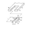
次に、縫合・結紮具12の形状とプッシャー14との係合について図15および図16に示す。本実施形態の縫合・結紮具12は後述するようにTi合金等のチタン材で形成されている。そして、縫合・結紮具12は略平行状態の2本の脚部121とこの脚部121を連結する基端部122を有して略コ字型に形成されている。 Next, FIG. 15 and FIG. 16 show the shape of the suturing / ligating
また、プッシャー14の凹状部16の内縁部には断面が略半円形状の突起40が長手方向に亘って形成されており、縫合・結紮具12の基端部122には縫合・結紮具12が変形した際に、突起40と係合する位置に係合溝41が形成されている。これによって縫合・結紮具12が変形途中でガイド部材13から遊離した時に、縫合・結紮具12が脱落したり、外乱によってその向きが変わってしまうことを防止している。また、このような一般に線材をプレス成形して製作される縫合・結紮具12では、素材の全長に亘って同一の断面形状の方が製造しやすいので、そのような場合には縫合・結紮具12の外周面全周(脚部121の外周)に亘って係合溝41が形成されていても良い。 A
また、縫合・結紮具12の材料であるチタン材は非常に硬く強度が高いことで知られており、塑性変形させるためには非常に強い力量を有する。そこで本実施形態の縫合・結紮具12にはプッシャー14によって変形される際に、所定の形状に変形しやすくするために脚部121および基端部122には切り欠き42が設けられており、この部分から折れ曲がるようになっている。そしてこの切り欠き42の部分はその他の部分に対して折れ曲がりやすければ良いので、切り欠き42の代わりにこの部分だけ局所的に焼きなましをする等の材質面での加工をすることによって、ヤング率を他の部分よりも比較的大きくして折れ曲がりやすくする、あるいは曲げ方向に対して他の部分よりも断面係数が比較的小さくなるように形成しても良い。 Titanium material, which is the material of the suture /
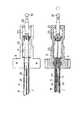
次に、アプライヤー1の動作について図17〜図22に基づいて説明する。図17は縫合・結紮具12aがガイド部材13に装填され、可動ハンドル9を第1段階まで操作した状態であり、この時には操作手段4の可動ハンドル9は図1の実線の位置にある。この状態において、プッシャー14は縫合・結紮具12aを支持ピン15とで保持しており、上下方向にはガイド部材13により保持されている。また、貯蔵手段19の内部の縫合・結紮具12のうち、縫合・結紮具12bはプッシャー14に設けられている掛止部20によってクリップ抑えスプリング22に抗して仕切板18の前方の開口部43に移動しつつある。 Next, the operation of the applier 1 will be described with reference to FIGS. FIG. 17 shows a state in which the suturing / ligating tool 12a is loaded on the
縫合・結紮具12の順列で縫合・結紮具12bの次の縫合・結紮具12cは縫合・結紮具12d以下後続の縫合・結紮具12がバッファー23に付勢されることによって、ワンウェイクラッチ21を乗り越えた位置に移動する位置に移動する。ワンウェイクラッチ21は金属板等の弾性部材で形成されており、その形状と相まって縫合・結紮具12を前方方向には移動可能とするが、一旦ワンウェイクラッチ21を乗り越えると後方には戻れないようになっている。 In the permutation of the suturing / ligating
図18に次の第2操作段階を示す。この状態では前記状態よりも可動ハンドル9が閉鎖方向に操作されることにより、プッシャー14がさらに前進し、その凹状部16の突起40により縫合・結紮具12aを前方に押す。これにより縫合・結紮具12aは支持ピン15により支持されているので、プッシャー14で押された部分が前方に折れ曲がり、切り欠き42によって所定の形状に変形して縫合・結紮具12aの先端同士が接触する。そして縫合・結紮具12aはガイド部材13から遊離していくが、変形していくに従って前述のようにプッシャー14の突起40と縫合・結紮具12aの係合溝41が係合していくので、取り付け操作中に取り付け手段2から脱落することは無い。 FIG. 18 shows the next second operation stage. In this state, when the
この際に貯蔵手段19の内部の縫合・結紮具12は掛止部20によって縫合・結紮具12bが前方に移動されることにより、クリップ押しスプリング24の付勢によりさらに前方に移動する。 At this time, the suturing / ligating
さらに、図19〜図21に示すように可動ハンドル9が閉鎖操作されるに従ってプッシャー14が前進し、次第に縫合・結紮具12aが変形されていくと共に、貯蔵手段19の内部の縫合・結紮具12も前方に送られていく。そして、図21の段階で可動ハンドル9は完全に閉鎖位置に達してプッシャー14が最前部まで移動し、縫合・結紮具12aは最終形状に変化される。 Further, as shown in FIGS. 19 to 21, as the
この段階において縫合・結紮具12bは仕切板18の開口部43の上部に移動し、クリップ抑えスプリング22によって開口部43の内部で、プッシャー14上面に装填される。そして、後続の縫合・結紮具12は続いて前方に移動する。 At this stage, the suturing / ligating
この時の縫合・結紮具12の最終形状は、前記2本の脚部121の略平行に近接している部分の長さが支持ピン15を包囲している部分の長さに対して約2倍以上となっており、不必要に最終形状の長さを長くしないようになっている。 The final shape of the suturing / ligating
次に、図22に示す段階に移る。この段階では可動ハンドル9は一連の操作を終了し、挿入部3の後端のメインスプリング29によって完全に解放位置に移動し、プッシャー14も最後位置に移動する。 Next, the process proceeds to the stage shown in FIG. At this stage, the
そして、縫合・結紮具12aとプッシャー14の係合は解除され、縫合・結紮具12aはガイド部材13の内部に設けられているイジェクター17の弾性力によってガイド部材13の側方外部に放出される。一般に、脈管50を結紮する場合には切断する側に1個、残す側に2個の縫合・結紮具12を取り付けることになっているが、そのような時に従来技術では結紮操作の度にアプライヤー1を脈管50から外さなければ、縫合・結紮具12を放出できなかったが、本実施形態では順番に側方にガイド部材13をずらしていくだけで次々と結紮が行えるので、一度ホールドした脈管50を逃す心配がない。Then, the engagement between the suture / ligator 12a and the
また、縫合・結紮具12bはプッシャー14が開口部43よりも後方に移動するために、クリップ抑えスプリング22の弾性力によりプッシャー14の前方に移動して次の操作に備える。後続の縫合・結紮具12はクリップ押しスプリング24の弾性力により、縫合・結紮具12bがクリップ抑えスプリング22と接触する位置まで移動し、アプライヤー1全体として初期状態に復帰する。 Further, since the
この状態から再び可動ハンドル9を閉鎖操作することにより、図17〜図22の一連の動作が繰り返され、縫合・結紮具12が連発されるようになっている。そして、最後の縫合・結紮具12tが放出されると、貯蔵手段19の内部には縫合・結紮具12が存在しなくなるが、この時には前述のようにバッファー23が最前位置に移動するので、その目視しやすい色調により縫合・結紮具12を使い果たしたことが確認される。また、縫合・結紮具12を使い果たした状態でさらに操作を行っても、このアプライヤー1では縫合・結紮具12を取り付けるための可動部分等が無いため、ただ単にプッシャー14が前進・後退をするのみであるので、生体組織を損傷する危険性がない。 By closing the
また、縫合・結紮具12を使い果たした時にさらに処置を続行する場合には、前述のように操作手段4の蓋体11を開放して挿入部3を操作手段4から取り外し、新しい挿入部3を操作手段4に組み込んで蓋体11を閉鎖し、アプライヤー1に新しい縫合・結紮具12を装備させる。 Further, when the treatment is continued when the suture /
ここで、図28および図29に示した従来の縫合・結紮具51と本実施形態の縫合・結紮具12とを比較すると、前述したように、縫合・結紮具51は、直径Dの脈管50を結紮するためには脚部52の長さが約2倍程度必要であり、2本の脚部52間距離L1 はL1 ≧Dとなっていなくてはならない。ここで従来技術の場合には縫合・結紮具51を変形させやすくするために、基端部53が角度θの略三角形状となっている。そのために全長はL2 +mcosθとなっており、本実施形態に示す場合に対してmcosθ長くなっている。 Here, when the conventional suturing / ligating
そして、アプライヤーに順列状態に貯蔵した場合、図29に示すように、縫合・結紮具51の2つにつきnだけの無駄な長さが必要となり、縫合・結紮具51の数が多くなればなる程その長さは増大し、結果として貯蔵部に貯蔵できる縫合・結紮具51の数が減少してしまう。本実施形態ではこの無駄な長さであるnが無いため、例えば20個では19nの長さが確保できるため、大体縫合・結紮具51を4個程度よけいに貯蔵することができるので、前述の従来の問題が解決される。 When the appliers are stored in a permuted state, as shown in FIG. 29, a wasteful length of n is required for each of the two stitching /
また、縫合・結紮具51が所定の形状に変形された時に、従来技術ではその全長がL2 +mとなるが、本実施形態ではL2 +l/2であるので、差引きm−l/2だけ生体内に残留する物質の大きさを小さくすることができる。 Further, when the suture /
以上のように、本実施形態によれば、この発明の目的である、安全・簡単な機構のアプライヤー1が使用できる、あるいは縫合・結紮具12の大きさを小さくしてアプライヤー1の内部に貯蔵できる数を増やす、または不必要に大きな残留物を生体内に残さない。さらには縫合・結紮具12で脈管50の結紮ができる等という点に沿った範囲であれば、アプライヤー1や縫合・結紮具12等の形状や構造には特に制限は無く、どのようなものでも構わない。 As described above, according to the present embodiment, the applier 1 having a safe and simple mechanism, which is the object of the present invention, can be used, or the size of the suturing / ligating
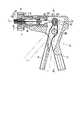
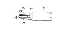
図23は第2の実施形態を示す。縫合・結紮具12の形状は第1の実施形態と同一であり、変形の際に角となる部分が曲がりやすくなっている等の特徴も同一である。アプライヤー54の取り付け手段55はジョー56がジョー閉鎖部材57が進退駆動されることにより閉鎖・開放され、それによりジョー56に装填されている縫合・結紮具12を所定の形状に変形させて目的の生体組織を縫合・結紮することができる。 FIG. 23 shows a second embodiment. The shape of the suturing / ligating
本実施形態においては、前述の第1の実施形態と同様に、縫合・結紮具12の形状が小さいためにアプライヤー1の内部に数多くの縫合・結紮具12を貯蔵できる、あるいは生体内に不必要に大きな残留物を残さずに済むというメリットがある。 In the present embodiment, as in the first embodiment described above, since the shape of the suturing / ligating
以上のようにアプライヤー1の内部に数多くの縫合・結紮具12を貯蔵できる、あるいは生体内に不必要な大きな残留物を残さないという、この発明の目的に沿った範囲であれば、縫合・結紮具12の構造・材質等に特に限定は無くどのようなものでも構わない。 As described above, a number of sutures and
図24および図25は第3の実施形態を示す。縫合・結紮具12の基本的な形状は第1の実施形態と同様であるが、図24では2本の脚部58の対向する面の端部にそれぞれ互いに係合するように突起59と凹部60が設けられている。図25では突起59がピン状の部材からなり、凹部60は脚部58に開けられた孔となっている。そして、これらが互いに係合することによって縫合・結紮具12が所定の形状に変形した際に、脚部58同士がずれることなく確実に略平行状態に近接して所定の形状に変形できるため、確実な縫合・結紮が可能となる。 24 and 25 show a third embodiment. The basic shape of the suturing / ligating
以上のように、この発明の目的である、確実な縫合・結紮を行うという点に沿っていれば、縫合・結紮具12の構造・材質等には特に制限は無く、どのようなものでも構わない。 As described above, the structure and material of the suturing / ligating
図26は第4の実施形態を示す。縫合・結紮具12の基本的な形状は第1の実施形態と同様であるが、図26では2本の脚部58の対向する面に、縫合・結紮具12が生体組織に取り付けられた際に、生体組織に対して滑って脱落することを防止するための滑り止め61が設けられており、本実施形態では前記対向する面を凸あるいは凹形状を適当に組み合わせた形状に形成しており、それにより生体組織に対して滑らないようになっている。 FIG. 26 shows a fourth embodiment. The basic shape of the suturing / ligating
図27は第5の実施形態を示す。縫合・結紮具12の基本的な形状は第1の実施形態と同様であるが、所定の形状に変形する際に角となる部分(脚部121、基端部122)の内側に切り欠き42等の凹みが設けられており、変形しやすくなっている。 FIG. 27 shows a fifth embodiment. The basic shape of the suturing / ligating
また、前記滑り止め61は、例えば前記2本の脚部58の対向する面を梨地仕上げとしても良く、そのような場合にはサンドブラストや化学的な表面処理によって、滑り止め61を形成することができる。 The anti-slip 61 may have, for example, a matte finish on the opposing surfaces of the two
以上のように、この発明の目的である、確実な縫合・結紮を行うという点に沿っていれば、縫合・結紮具12の構造・材質等には特に制限は無く、どのようなものでも構わない。 As described above, the structure and material of the suturing / ligating
前記実施形態によれば、次のような構成が得られる。 According to the embodiment, the following configuration is obtained.
(付記1)生体組織を縫合・結紮等をするための縫合・結紮具において、略平行状態の2本の脚部とこの脚部を連結する基端部を有して略コ字型に形成されており、生体組織に取り付ける際に所定の形状に変形して取り付けられ、前記2本の脚部は前記基端部に対して略垂直で、変形後、前記2本の脚部の互いに向かい合う面同士が少なくとも部分的に接触するように構成されていることを特徴とする縫合・結紮具。 (Supplementary note 1) In a suturing / ligating tool for suturing / ligating a living tissue, it is formed in a substantially U-shape having two legs in a substantially parallel state and a base end for connecting the legs. The two legs are substantially perpendicular to the base end when attached to a living tissue, and the two legs face each other after being deformed. A suturing / ligating tool characterized in that the surfaces are at least partially in contact with each other.
(付記2)生体組織を縫合・結紮等をするための縫合・結紮具において、略平行状態の2本の脚部とこの脚部を連結する基端部を有して略コ字型に形成されており、生体組織に取り付ける際の変形後の形状が、前記2本の脚部の互いに向き合う面同士が近接し略平行状態となり、前記2本の脚部の基端部側には少なくとも一部分、前記2本の脚部が近接しない箇所を有し、前記2本の脚部部と前記基端部とによって囲まれた空間を有することを特徴とする縫合・結紮具。 (Supplementary note 2) A suture / ligator for suturing / ligating biological tissue has a substantially U-shape with two substantially parallel legs and a base end connecting the legs. The deformed shape when attached to the living tissue is such that the faces of the two legs facing each other are close to each other and are substantially parallel, and at least partly on the proximal end side of the two legs. A suturing / ligating tool having a portion where the two leg portions are not close to each other and a space surrounded by the two leg portions and the base end portion.
(付記3)生体組織を縫合・結紮するための縫合・結紮具で、略平行状態の2本の脚部とその脚部を接続する基端部を有して略コ字型に形成されており、前記2本の脚部は前記基端部に対して略垂直に形成されており、前記縫合・結紮具を生体組織に取り付けるためのアプライヤーにおいて、前記縫合・結紮具を保持する少なくとも一つの保持部材と、前記保持部材との間に前記縫合・結紮具を挟み込んで、前記縫合・結紮具の基端部を押圧することにより、前記縫合・結紮具を所定の形状に変形させるためのプッシャーを有し、前記縫合・結紮具の前記2本の脚部の向かい合う面同士が少なくとも部分的に接触するように変形させることを特徴とするアプライヤー。 (Supplementary Note 3) A suturing / ligating tool for suturing / ligating biological tissue, having two substantially parallel legs and a base end connecting the legs, and having a substantially U-shape. The two leg portions are formed substantially perpendicular to the proximal end portion, and in an applier for attaching the suturing / ligating tool to a living tissue, at least one holding the suturing / ligating tool. Sandwiching the suturing / ligating tool between two holding members and the holding member and pressing the base end of the suturing / ligating tool to deform the suturing / ligating tool into a predetermined shape An applier having a pusher and being deformed so that opposing surfaces of the two legs of the suturing / ligating tool are at least partially in contact with each other.
(付記4)生体組織を縫合・結紮するための縫合・結紮具を生体組織に取り付けるためのアプライヤーにおいて、前記アプライヤーの前記縫合・結紮具を生体組織に取り付けるための取り付け手段が、前記縫合・結紮具を所定の形状に変形させるための略ジョー状の互いに近接・離合する可動部材からなるアプライヤー。 (Appendix 4) An applier for attaching a suturing / ligating tool for suturing / ligating a living tissue to the living tissue, wherein an attaching means for attaching the suturing / ligating tool of the applier to the living tissue is the suturing An applier made up of a substantially jaw-shaped movable member that approaches and separates from each other for deforming the ligature tool into a predetermined shape.
(付記5)付記4において、前記縫合・結紮具の所定の形状が前記2本の脚部の向かい合う面同士が少なくとも部分的に接触するように形成されているアプライヤー。 (Appendix 5) The applier according to
(付記6)付記1,2において、前記脚部の長さが前記2本の脚部の脚部間距離の少なくとも0.5倍以上ある縫合・結紮具。 (Supplementary note 6) The suturing / ligating tool according to
(付記7)付記6において、前記所定の形状が、
a.前記2本の脚部の互いに向き合う面同士が近接し略平行状態となり、
b.前記2本の脚部の基端部側には少なくとも一部分、前記2本の脚部が近接しない箇所を有し、
c.前記2本の脚部と前記基端部とによって囲まれた空間を有する、
縫合・結紮具。(Appendix 7) In
a. The surfaces of the two legs facing each other are close to each other and in a substantially parallel state,
b. At least a part of the base end portion side of the two legs, a portion where the two legs are not close to each other,
c. A space surrounded by the two legs and the base end;
Suture and ligature.
(付記8)付記6において、前記所定の形状が、
a.前記2本の脚部の互いに向き合う面同士が近接し略平行状態となり、
b.前記2本の脚部の基端部側には少なくとも一部分、前記2本の脚部が近接しない箇所を有し、
c.前記2本の脚部と前記基端部とによって囲まれた空間を有し、
d.前記空間が前記保持部材を取り囲むように形成される、
縫合・結紮具。(Appendix 8) In
a. The surfaces of the two legs facing each other are close to each other and in a substantially parallel state,
b. At least a part of the base end portion side of the two legs, a portion where the two legs are not close to each other,
c. A space surrounded by the two legs and the base end;
d. The space is formed so as to surround the holding member.
Suture and ligature.
(付記9)付記1,2,7,8において、前記脚部の略平行状態となっている部分の長さが前記空間部分の長手方向の長さに対して、少なくとも2倍以上ある縫合・結紮具。 (Additional remark 9) In
(付記10)付記1,2,9において、前記脚部が所定の形状に変形しやすいように、所定の形状に変形した際に角となる部分が、他の部分に対して比較的変形しやすいように形成されている縫合・結紮具。 (Additional remark 10) In
(付記11)付記10において、前記脚部の比較的変形しやすい部分のヤング率が他の部分よりも比較的大きく形成されている縫合・結紮具。 (Supplementary note 11) The suturing / ligating tool according to
(付記12)付記10において、前記脚部の比較的変形しやすい部分の断面積が他の部分よりも比較的小さく形成されている縫合・結紮具。 (Supplementary note 12) The suturing / ligating tool according to
(付記13)付記10において、前記脚部の比較的変形しやすい部分の曲げ方向に対する断面係数が他の部分よりも比較的小さく形成されている縫合・結紮具。 (Supplementary note 13) The suturing / ligating tool according to
(付記14)付記12,13において、前記脚部の変形しやすい部分は、前記縫合・結紮具が所定の形状に変形する際に、前記角の外側となる部分または内側となる部分に切り欠きあるいは凹部が形成されている縫合・結紮具。 (Additional remark 14) In
(付記15)付記1,2,6〜14において、前記脚部を所定の形状に変形した際に、前記2本の脚部の互いに接触する部分の片方の脚部に突起が設けてあり、他方の脚部には前記突起と係合する凹部が形成されている縫合・結紮具。 (Appendix 15) In
(付記16)付記1,2,6〜15において、前記縫合・結紮具の外周面の少なくとも一部分に、前記縫合・結紮具を生体組織に取り付けるためのアプライヤーの取り付け手段と係合するための、突起あるいは凹部またはその両方が形成されている縫合・結紮具。 (Additional remark 16) In
(付記17)付記16において、前記突起あるいは凹部またはその両方が形成されている部分が、前記脚部の基端部である縫合・結紮具。 (Supplementary note 17) The suturing / ligating tool according to
(付記18)付記17において、前記突起あるいは凹部またはその両方が縫合・結紮具の外周面全周に形成されている縫合・結紮具。 (Supplementary note 18) The suturing / ligating tool according to
(付記19)付記16において、前記2本の脚部のお互いに向かい合う面に、少なくとも一つ以上の滑り止めのための凸部あるいは凹部が設けられている縫合・結紮具。 (Supplementary note 19) The suturing / ligating tool according to
付記1〜3,8によれば、従来技術の問題点である、縫合・結紮具においてはアプライヤーの構造が複雑でその挿入径が太くなる点を解決でき、脈管を確実に解決できる。 According to the supplementary notes 1 to 3 and 8, it is possible to solve the problem that the applier has a complicated structure of the applier and the insertion diameter becomes large in the suturing / ligating tool, which is a problem of the prior art, and the vessel can be surely solved.
付記4,5によれば、従来技術の問題点である、縫合・結紮具の全長が不必要に長いために不必要に大きな残留物を生体内に留めてしまう、あるいはアプライヤー内部に数多くのクリップを貯蔵できないという点について解決できる。 According to
付記6,7の効果は付記1〜5と同様である。付記8の効果は付記1,2,4と同様である。 The effects of
付記10〜14によれば、付記1〜9の効果に加え、従来技術の問題点であるアプライヤーの操作手段のストロークが大きい、あるいは縫合・結紮具の大きさが不必要に大きくなりがちであるという点について解決できる。 According to Appendices 10-14, in addition to the effects of Appendices 1-9, the stroke of the applier operating means which is a problem of the prior art tends to be large, or the size of the suturing / ligating tool tends to be unnecessarily large. You can solve the problem.
付記15の効果は付記1〜3,5〜14の効果に加え、従来技術の問題点である前記縫合・結紮具の前記2本の脚部が、互いに対向して近接せずにずれてしまうという点について解決できる。 The effect of
付記16〜18の効果は付記1〜15の効果に加え、従来技術の問題点である前記縫合・結紮具が、前記取り付け手段から脱落してしまうという点について解決できる。 The effects of
付記19の効果は付記1〜18の効果に加え、従来技術の問題点である前記縫合・結紮具が生体組織から脱落してしまうという点について解決できる。 In addition to the effects of Supplementary Notes 1 to 18, the effect of
1…アプライヤー、3…挿入部、4…操作手段、12…縫合・結紮具、14…プッシャー(第2の押圧部)、15…支持ピン(第1の押圧部)、121…脚部、122…基端部 DESCRIPTION OF SYMBOLS 1 ... Applier, 3 ... Insertion part, 4 ... Operation means, 12 ... Suture / ligation tool, 14 ... Pusher (2nd press part), 15 ... Support pin (1st press part), 121 ... Leg part, 122 ... Base end
Claims (3)
Translated fromJapanese先端と基端とを有する細長の挿入部と、
前記挿入部の先端側に設けられ、前記縫合・結紮具の前記空間内に位置し、前記基端部の長手方向の中間部を支持する支持部材と、
前記挿入部に対して前後方向に移動可能に設けられ、先端部に前記縫合・結紮具の基端部の中間部を避け、両端側を前記挿入部の先端方向に押圧して前記縫合・結紮具を塑性変形させる2箇所の押圧部を有する押圧手段と、
前記挿入部の基端に設けられ、前記挿入部に対して前記押圧手段を移動させる操作手段と、
を備え、
前記支持部材は、前記縫合・結紮具の基端部における長手方向の中間部を支持し、前記押圧手段は、前記操作手段の操作により前記挿入部の先端方向に移動することにより、前記縫合・結紮具の基端部における長手方向の両端部を前記2箇所の押圧部で同時に押圧して前記縫合・結紮具の前記折り曲げ部を折り曲げ、前記2本の脚部の先端同士を接触させた後、前記2本の脚部同士を略平行に近接させることを特徴とする縫合・結紮具アプライヤー。Two elongated legs having a distal end and a proximal end, and a proximal end connected to the proximal end of the legs so that a living tissue can be inserted between the two legs. The leg portion is substantially parallel, has a space surrounded by the leg portion and the base end portion, and further has a suture / ligating tool having a bent portion at the base end portion that is easier to bend than other portions. A suture / ligator applier for suturing and ligating living tissue,
An elongated insertion portion having a distal end and a proximal end;
A support member provided on the distal end side of the insertion portion, located in the space of the suturing / ligating tool, and supporting an intermediate portion in the longitudinal direction of the proximal end portion;
It is provided so as to be movable in the front-rear direction with respect to the insertion portion,avoids anintermediate portion of the proximal end portion of the suturing / ligating tool at the distal end portion, and presses both ends in the distal end direction of the inserting portion, thereby suturing / ligatingA pressing meanshaving two pressing portions for plastically deforming the tool;
An operating means provided at a proximal end of the insertion portion, and moving the pressing means relative to the insertion portion;
With
The support member supports an intermediate portion in the longitudinal direction at the proximal end portion of the suturing / ligating tool, and the pressing means moves in the distal direction of the insertion portion by operation of the operating means, thereby Afterpressing both ends in the longitudinal direction at the proximal end of the ligation toolsimultaneously with thetwo pressing portions to fold the bent portion of the suturing / ligating tooland bringing the tips of the two leg portions into contact with each other A suturing / ligating applier, wherein the two legs are brought close to each other in parallel .
先端と基端とを有する細長の挿入部と、
前記挿入部の先端側に設けられ、前記縫合・結紮具の前記空間内に位置し、前記基端部の長手方向の中間部を支持する支持部材と、
前記挿入部に対して前後方向に移動可能に設けられ、先端部に前記縫合・結紮具の基端部の両端側を前記挿入部の先端方向に押圧して前記縫合・結紮具を塑性変形させる押圧手段と、
前記挿入部の基端に設けられ、前記挿入部に対して前記押圧手段を移動させる操作手段と、
を備え、
前記支持部材は、前記縫合・結紮具の基端部における長手方向の中間部を支持し、前記押圧手段は、前記操作手段の操作により前記挿入部の先端方向に移動することにより、前記縫合・結紮具の基端部における長手方向の両端部を前記2箇所の押圧部で同時に押圧し、該基端部を折り曲げて前記2本の脚部の先端同士を接触させた後、前記2本の脚部の折り曲げ部を折り曲げ、前記2本の脚部同士を略平行に近接させることを特徴とする縫合・結紮具アプライヤー。Two elongated legs having a distal end and a proximal end, and a proximal end connected to the proximal end of the legs so that a living tissue can be inserted between the two legs. The leg portion is substantially parallel, has a space surrounded by the leg portion and the base end portion, and further uses a suturing / ligating tool having a bent portion at the leg portion that is easier to bend than other portions. A suture / ligator applier for suturing and ligating biological tissue,
An elongated insertion portion having a distal end and a proximal end;
A support member provided on the distal end side of the insertion portion, located in the space of the suturing / ligating tool, and supporting an intermediate portion in the longitudinal direction of the proximal end portion;
It is provided so as to be movable in the front-rear direction with respect to the insertion portion, and both ends of the base end portion of the suturing / ligating tool are pressed toward the distal end of the inserting portion at the distal end portion to plastically deform the suturing / ligating tool. Pressing means;
An operating means provided at a proximal end of the insertion portion, and moving the pressing means relative to the insertion portion;
With
The support member supports an intermediate portion in the longitudinal direction of the proximal end portion of the suturing / ligating tool, and the pressing means moves in the distal direction of the insertion portion by operation of the operating means, thereby The two end portions in the longitudinal direction of the base end portion of the ligature tool aresimultaneously pressed by thetwo pressing portions, the base end portions are bent andthe tips of the two leg portions are brought into contact with each other, and then the two A suture / ligatorapplier, wherein a bent portion of a leg is bent and the two legs are brought close to each other in parallel .
Priority Applications (1)
| Application Number | Priority Date | Filing Date | Title |
|---|---|---|---|
| JP2006102022AJP4102409B2 (en) | 2006-04-03 | 2006-04-03 | Suture and ligature applier |
Applications Claiming Priority (1)
| Application Number | Priority Date | Filing Date | Title |
|---|---|---|---|
| JP2006102022AJP4102409B2 (en) | 2006-04-03 | 2006-04-03 | Suture and ligature applier |
Related Parent Applications (1)
| Application Number | Title | Priority Date | Filing Date |
|---|---|---|---|
| JP8037873ADivisionJPH09224944A (en) | 1996-02-26 | 1996-02-26 | Suturing/ligating tool |
Publications (2)
| Publication Number | Publication Date |
|---|---|
| JP2006187649A JP2006187649A (en) | 2006-07-20 |
| JP4102409B2true JP4102409B2 (en) | 2008-06-18 |
Family
ID=36795313
Family Applications (1)
| Application Number | Title | Priority Date | Filing Date |
|---|---|---|---|
| JP2006102022AExpired - Fee RelatedJP4102409B2 (en) | 2006-04-03 | 2006-04-03 | Suture and ligature applier |
Country Status (1)
| Country | Link |
|---|---|
| JP (1) | JP4102409B2 (en) |
Families Citing this family (505)
| Publication number | Priority date | Publication date | Assignee | Title |
|---|---|---|---|---|
| US20070084897A1 (en) | 2003-05-20 | 2007-04-19 | Shelton Frederick E Iv | Articulating surgical stapling instrument incorporating a two-piece e-beam firing mechanism |
| US9060770B2 (en) | 2003-05-20 | 2015-06-23 | Ethicon Endo-Surgery, Inc. | Robotically-driven surgical instrument with E-beam driver |
| US11890012B2 (en) | 2004-07-28 | 2024-02-06 | Cilag Gmbh International | Staple cartridge comprising cartridge body and attached support |
| US11998198B2 (en) | 2004-07-28 | 2024-06-04 | Cilag Gmbh International | Surgical stapling instrument incorporating a two-piece E-beam firing mechanism |
| US8215531B2 (en) | 2004-07-28 | 2012-07-10 | Ethicon Endo-Surgery, Inc. | Surgical stapling instrument having a medical substance dispenser |
| US9072535B2 (en) | 2011-05-27 | 2015-07-07 | Ethicon Endo-Surgery, Inc. | Surgical stapling instruments with rotatable staple deployment arrangements |
| US9237891B2 (en) | 2005-08-31 | 2016-01-19 | Ethicon Endo-Surgery, Inc. | Robotically-controlled surgical stapling devices that produce formed staples having different lengths |
| US7673781B2 (en) | 2005-08-31 | 2010-03-09 | Ethicon Endo-Surgery, Inc. | Surgical stapling device with staple driver that supports multiple wire diameter staples |
| US7669746B2 (en) | 2005-08-31 | 2010-03-02 | Ethicon Endo-Surgery, Inc. | Staple cartridges for forming staples having differing formed staple heights |
| US11246590B2 (en) | 2005-08-31 | 2022-02-15 | Cilag Gmbh International | Staple cartridge including staple drivers having different unfired heights |
| US7934630B2 (en) | 2005-08-31 | 2011-05-03 | Ethicon Endo-Surgery, Inc. | Staple cartridges for forming staples having differing formed staple heights |
| US10159482B2 (en) | 2005-08-31 | 2018-12-25 | Ethicon Llc | Fastener cartridge assembly comprising a fixed anvil and different staple heights |
| US11484312B2 (en) | 2005-08-31 | 2022-11-01 | Cilag Gmbh International | Staple cartridge comprising a staple driver arrangement |
| US20070106317A1 (en) | 2005-11-09 | 2007-05-10 | Shelton Frederick E Iv | Hydraulically and electrically actuated articulation joints for surgical instruments |
| US8708213B2 (en) | 2006-01-31 | 2014-04-29 | Ethicon Endo-Surgery, Inc. | Surgical instrument having a feedback system |
| US8161977B2 (en) | 2006-01-31 | 2012-04-24 | Ethicon Endo-Surgery, Inc. | Accessing data stored in a memory of a surgical instrument |
| US11793518B2 (en) | 2006-01-31 | 2023-10-24 | Cilag Gmbh International | Powered surgical instruments with firing system lockout arrangements |
| US7845537B2 (en) | 2006-01-31 | 2010-12-07 | Ethicon Endo-Surgery, Inc. | Surgical instrument having recording capabilities |
| US11224427B2 (en) | 2006-01-31 | 2022-01-18 | Cilag Gmbh International | Surgical stapling system including a console and retraction assembly |
| US11278279B2 (en) | 2006-01-31 | 2022-03-22 | Cilag Gmbh International | Surgical instrument assembly |
| US20120292367A1 (en) | 2006-01-31 | 2012-11-22 | Ethicon Endo-Surgery, Inc. | Robotically-controlled end effector |
| US8820603B2 (en) | 2006-01-31 | 2014-09-02 | Ethicon Endo-Surgery, Inc. | Accessing data stored in a memory of a surgical instrument |
| US8186555B2 (en) | 2006-01-31 | 2012-05-29 | Ethicon Endo-Surgery, Inc. | Motor-driven surgical cutting and fastening instrument with mechanical closure system |
| US7753904B2 (en) | 2006-01-31 | 2010-07-13 | Ethicon Endo-Surgery, Inc. | Endoscopic surgical instrument with a handle that can articulate with respect to the shaft |
| US20110024477A1 (en) | 2009-02-06 | 2011-02-03 | Hall Steven G | Driven Surgical Stapler Improvements |
| US20110295295A1 (en) | 2006-01-31 | 2011-12-01 | Ethicon Endo-Surgery, Inc. | Robotically-controlled surgical instrument having recording capabilities |
| US9861359B2 (en) | 2006-01-31 | 2018-01-09 | Ethicon Llc | Powered surgical instruments with firing system lockout arrangements |
| US8992422B2 (en) | 2006-03-23 | 2015-03-31 | Ethicon Endo-Surgery, Inc. | Robotically-controlled endoscopic accessory channel |
| US8236010B2 (en) | 2006-03-23 | 2012-08-07 | Ethicon Endo-Surgery, Inc. | Surgical fastener and cutter with mimicking end effector |
| US8322455B2 (en) | 2006-06-27 | 2012-12-04 | Ethicon Endo-Surgery, Inc. | Manually driven surgical cutting and fastening instrument |
| US10130359B2 (en) | 2006-09-29 | 2018-11-20 | Ethicon Llc | Method for forming a staple |
| US7506791B2 (en)* | 2006-09-29 | 2009-03-24 | Ethicon Endo-Surgery, Inc. | Surgical stapling instrument with mechanical mechanism for limiting maximum tissue compression |
| US10568652B2 (en) | 2006-09-29 | 2020-02-25 | Ethicon Llc | Surgical staples having attached drivers of different heights and stapling instruments for deploying the same |
| US11980366B2 (en) | 2006-10-03 | 2024-05-14 | Cilag Gmbh International | Surgical instrument |
| US8684253B2 (en) | 2007-01-10 | 2014-04-01 | Ethicon Endo-Surgery, Inc. | Surgical instrument with wireless communication between a control unit of a robotic system and remote sensor |
| US8632535B2 (en) | 2007-01-10 | 2014-01-21 | Ethicon Endo-Surgery, Inc. | Interlock and surgical instrument including same |
| US11291441B2 (en) | 2007-01-10 | 2022-04-05 | Cilag Gmbh International | Surgical instrument with wireless communication between control unit and remote sensor |
| US8652120B2 (en) | 2007-01-10 | 2014-02-18 | Ethicon Endo-Surgery, Inc. | Surgical instrument with wireless communication between control unit and sensor transponders |
| US20080169333A1 (en) | 2007-01-11 | 2008-07-17 | Shelton Frederick E | Surgical stapler end effector with tapered distal end |
| US11039836B2 (en) | 2007-01-11 | 2021-06-22 | Cilag Gmbh International | Staple cartridge for use with a surgical stapling instrument |
| US7673782B2 (en) | 2007-03-15 | 2010-03-09 | Ethicon Endo-Surgery, Inc. | Surgical stapling instrument having a releasable buttress material |
| US8893946B2 (en) | 2007-03-28 | 2014-11-25 | Ethicon Endo-Surgery, Inc. | Laparoscopic tissue thickness and clamp load measuring devices |
| US11564682B2 (en) | 2007-06-04 | 2023-01-31 | Cilag Gmbh International | Surgical stapler device |
| US8931682B2 (en) | 2007-06-04 | 2015-01-13 | Ethicon Endo-Surgery, Inc. | Robotically-controlled shaft based rotary drive systems for surgical instruments |
| US8408439B2 (en) | 2007-06-22 | 2013-04-02 | Ethicon Endo-Surgery, Inc. | Surgical stapling instrument with an articulatable end effector |
| US7753245B2 (en) | 2007-06-22 | 2010-07-13 | Ethicon Endo-Surgery, Inc. | Surgical stapling instruments |
| US11849941B2 (en) | 2007-06-29 | 2023-12-26 | Cilag Gmbh International | Staple cartridge having staple cavities extending at a transverse angle relative to a longitudinal cartridge axis |
| US8561870B2 (en) | 2008-02-13 | 2013-10-22 | Ethicon Endo-Surgery, Inc. | Surgical stapling instrument |
| US9179912B2 (en) | 2008-02-14 | 2015-11-10 | Ethicon Endo-Surgery, Inc. | Robotically-controlled motorized surgical cutting and fastening instrument |
| US8573465B2 (en) | 2008-02-14 | 2013-11-05 | Ethicon Endo-Surgery, Inc. | Robotically-controlled surgical end effector system with rotary actuated closure systems |
| US8758391B2 (en) | 2008-02-14 | 2014-06-24 | Ethicon Endo-Surgery, Inc. | Interchangeable tools for surgical instruments |
| US7819298B2 (en) | 2008-02-14 | 2010-10-26 | Ethicon Endo-Surgery, Inc. | Surgical stapling apparatus with control features operable with one hand |
| US8752749B2 (en) | 2008-02-14 | 2014-06-17 | Ethicon Endo-Surgery, Inc. | Robotically-controlled disposable motor-driven loading unit |
| US8657174B2 (en) | 2008-02-14 | 2014-02-25 | Ethicon Endo-Surgery, Inc. | Motorized surgical cutting and fastening instrument having handle based power source |
| US7866527B2 (en) | 2008-02-14 | 2011-01-11 | Ethicon Endo-Surgery, Inc. | Surgical stapling apparatus with interlockable firing system |
| US11986183B2 (en) | 2008-02-14 | 2024-05-21 | Cilag Gmbh International | Surgical cutting and fastening instrument comprising a plurality of sensors to measure an electrical parameter |
| JP5410110B2 (en) | 2008-02-14 | 2014-02-05 | エシコン・エンド−サージェリィ・インコーポレイテッド | Surgical cutting / fixing instrument with RF electrode |
| US8636736B2 (en) | 2008-02-14 | 2014-01-28 | Ethicon Endo-Surgery, Inc. | Motorized surgical cutting and fastening instrument |
| US9585657B2 (en) | 2008-02-15 | 2017-03-07 | Ethicon Endo-Surgery, Llc | Actuator for releasing a layer of material from a surgical end effector |
| US20090206131A1 (en) | 2008-02-15 | 2009-08-20 | Ethicon Endo-Surgery, Inc. | End effector coupling arrangements for a surgical cutting and stapling instrument |
| US11272927B2 (en) | 2008-02-15 | 2022-03-15 | Cilag Gmbh International | Layer arrangements for surgical staple cartridges |
| US7954686B2 (en) | 2008-09-19 | 2011-06-07 | Ethicon Endo-Surgery, Inc. | Surgical stapler with apparatus for adjusting staple height |
| PL3476312T3 (en) | 2008-09-19 | 2024-03-11 | Ethicon Llc | Surgical stapler with apparatus for adjusting staple height |
| US9005230B2 (en) | 2008-09-23 | 2015-04-14 | Ethicon Endo-Surgery, Inc. | Motorized surgical instrument |
| US8210411B2 (en) | 2008-09-23 | 2012-07-03 | Ethicon Endo-Surgery, Inc. | Motor-driven surgical cutting instrument |
| US11648005B2 (en) | 2008-09-23 | 2023-05-16 | Cilag Gmbh International | Robotically-controlled motorized surgical instrument with an end effector |
| US9386983B2 (en) | 2008-09-23 | 2016-07-12 | Ethicon Endo-Surgery, Llc | Robotically-controlled motorized surgical instrument |
| US8608045B2 (en) | 2008-10-10 | 2013-12-17 | Ethicon Endo-Sugery, Inc. | Powered surgical cutting and stapling apparatus with manually retractable firing system |
| US8517239B2 (en) | 2009-02-05 | 2013-08-27 | Ethicon Endo-Surgery, Inc. | Surgical stapling instrument comprising a magnetic element driver |
| US8444036B2 (en) | 2009-02-06 | 2013-05-21 | Ethicon Endo-Surgery, Inc. | Motor driven surgical fastener device with mechanisms for adjusting a tissue gap within the end effector |
| RU2525225C2 (en) | 2009-02-06 | 2014-08-10 | Этикон Эндо-Серджери, Инк. | Improvement of drive surgical suturing instrument |
| US8453907B2 (en) | 2009-02-06 | 2013-06-04 | Ethicon Endo-Surgery, Inc. | Motor driven surgical fastener device with cutting member reversing mechanism |
| US8851354B2 (en) | 2009-12-24 | 2014-10-07 | Ethicon Endo-Surgery, Inc. | Surgical cutting instrument that analyzes tissue thickness |
| US8220688B2 (en) | 2009-12-24 | 2012-07-17 | Ethicon Endo-Surgery, Inc. | Motor-driven surgical cutting instrument with electric actuator directional control assembly |
| US8608046B2 (en) | 2010-01-07 | 2013-12-17 | Ethicon Endo-Surgery, Inc. | Test device for a surgical tool |
| US8783543B2 (en) | 2010-07-30 | 2014-07-22 | Ethicon Endo-Surgery, Inc. | Tissue acquisition arrangements and methods for surgical stapling devices |
| US8360296B2 (en) | 2010-09-09 | 2013-01-29 | Ethicon Endo-Surgery, Inc. | Surgical stapling head assembly with firing lockout for a surgical stapler |
| US8632525B2 (en) | 2010-09-17 | 2014-01-21 | Ethicon Endo-Surgery, Inc. | Power control arrangements for surgical instruments and batteries |
| US9289212B2 (en) | 2010-09-17 | 2016-03-22 | Ethicon Endo-Surgery, Inc. | Surgical instruments and batteries for surgical instruments |
| US20120078244A1 (en) | 2010-09-24 | 2012-03-29 | Worrell Barry C | Control features for articulating surgical device |
| US8733613B2 (en) | 2010-09-29 | 2014-05-27 | Ethicon Endo-Surgery, Inc. | Staple cartridge |
| US11812965B2 (en) | 2010-09-30 | 2023-11-14 | Cilag Gmbh International | Layer of material for a surgical end effector |
| US11298125B2 (en) | 2010-09-30 | 2022-04-12 | Cilag Gmbh International | Tissue stapler having a thickness compensator |
| US12213666B2 (en) | 2010-09-30 | 2025-02-04 | Cilag Gmbh International | Tissue thickness compensator comprising layers |
| US9016542B2 (en) | 2010-09-30 | 2015-04-28 | Ethicon Endo-Surgery, Inc. | Staple cartridge comprising compressible distortion resistant components |
| US9364233B2 (en) | 2010-09-30 | 2016-06-14 | Ethicon Endo-Surgery, Llc | Tissue thickness compensators for circular surgical staplers |
| US9277919B2 (en) | 2010-09-30 | 2016-03-08 | Ethicon Endo-Surgery, Llc | Tissue thickness compensator comprising fibers to produce a resilient load |
| US11925354B2 (en) | 2010-09-30 | 2024-03-12 | Cilag Gmbh International | Staple cartridge comprising staples positioned within a compressible portion thereof |
| US9314246B2 (en) | 2010-09-30 | 2016-04-19 | Ethicon Endo-Surgery, Llc | Tissue stapler having a thickness compensator incorporating an anti-inflammatory agent |
| US9301752B2 (en) | 2010-09-30 | 2016-04-05 | Ethicon Endo-Surgery, Llc | Tissue thickness compensator comprising a plurality of capsules |
| RU2013119928A (en) | 2010-09-30 | 2014-11-10 | Этикон Эндо-Серджери, Инк. | A STAPLING SYSTEM CONTAINING A RETAINING MATRIX AND A LEVELING MATRIX |
| US10945731B2 (en) | 2010-09-30 | 2021-03-16 | Ethicon Llc | Tissue thickness compensator comprising controlled release and expansion |
| US9386988B2 (en) | 2010-09-30 | 2016-07-12 | Ethicon End-Surgery, LLC | Retainer assembly including a tissue thickness compensator |
| US8893949B2 (en) | 2010-09-30 | 2014-11-25 | Ethicon Endo-Surgery, Inc. | Surgical stapler with floating anvil |
| US9351730B2 (en) | 2011-04-29 | 2016-05-31 | Ethicon Endo-Surgery, Llc | Tissue thickness compensator comprising channels |
| US9220501B2 (en) | 2010-09-30 | 2015-12-29 | Ethicon Endo-Surgery, Inc. | Tissue thickness compensators |
| US9629814B2 (en) | 2010-09-30 | 2017-04-25 | Ethicon Endo-Surgery, Llc | Tissue thickness compensator configured to redistribute compressive forces |
| US9307989B2 (en) | 2012-03-28 | 2016-04-12 | Ethicon Endo-Surgery, Llc | Tissue stapler having a thickness compensator incorportating a hydrophobic agent |
| US9332974B2 (en) | 2010-09-30 | 2016-05-10 | Ethicon Endo-Surgery, Llc | Layered tissue thickness compensator |
| US9301753B2 (en) | 2010-09-30 | 2016-04-05 | Ethicon Endo-Surgery, Llc | Expandable tissue thickness compensator |
| US9232941B2 (en) | 2010-09-30 | 2016-01-12 | Ethicon Endo-Surgery, Inc. | Tissue thickness compensator comprising a reservoir |
| US9055941B2 (en) | 2011-09-23 | 2015-06-16 | Ethicon Endo-Surgery, Inc. | Staple cartridge including collapsible deck |
| US9788834B2 (en) | 2010-09-30 | 2017-10-17 | Ethicon Llc | Layer comprising deployable attachment members |
| US8695866B2 (en) | 2010-10-01 | 2014-04-15 | Ethicon Endo-Surgery, Inc. | Surgical instrument having a power control circuit |
| US9211122B2 (en) | 2011-03-14 | 2015-12-15 | Ethicon Endo-Surgery, Inc. | Surgical access devices with anvil introduction and specimen retrieval structures |
| AU2012250197B2 (en) | 2011-04-29 | 2017-08-10 | Ethicon Endo-Surgery, Inc. | Staple cartridge comprising staples positioned within a compressible portion thereof |
| US11207064B2 (en) | 2011-05-27 | 2021-12-28 | Cilag Gmbh International | Automated end effector component reloading system for use with a robotic system |
| US8833632B2 (en) | 2011-09-06 | 2014-09-16 | Ethicon Endo-Surgery, Inc. | Firing member displacement system for a stapling instrument |
| US9050084B2 (en) | 2011-09-23 | 2015-06-09 | Ethicon Endo-Surgery, Inc. | Staple cartridge including collapsible deck arrangement |
| US9044230B2 (en) | 2012-02-13 | 2015-06-02 | Ethicon Endo-Surgery, Inc. | Surgical cutting and fastening instrument with apparatus for determining cartridge and firing motion status |
| US9078653B2 (en) | 2012-03-26 | 2015-07-14 | Ethicon Endo-Surgery, Inc. | Surgical stapling device with lockout system for preventing actuation in the absence of an installed staple cartridge |
| BR112014024098B1 (en) | 2012-03-28 | 2021-05-25 | Ethicon Endo-Surgery, Inc. | staple cartridge |
| MX358135B (en) | 2012-03-28 | 2018-08-06 | Ethicon Endo Surgery Inc | Tissue thickness compensator comprising a plurality of layers. |
| US9198662B2 (en) | 2012-03-28 | 2015-12-01 | Ethicon Endo-Surgery, Inc. | Tissue thickness compensator having improved visibility |
| JP6224070B2 (en) | 2012-03-28 | 2017-11-01 | エシコン・エンド−サージェリィ・インコーポレイテッドEthicon Endo−Surgery,Inc. | Retainer assembly including tissue thickness compensator |
| US9101358B2 (en) | 2012-06-15 | 2015-08-11 | Ethicon Endo-Surgery, Inc. | Articulatable surgical instrument comprising a firing drive |
| US9072536B2 (en) | 2012-06-28 | 2015-07-07 | Ethicon Endo-Surgery, Inc. | Differential locking arrangements for rotary powered surgical instruments |
| BR112014032776B1 (en) | 2012-06-28 | 2021-09-08 | Ethicon Endo-Surgery, Inc | SURGICAL INSTRUMENT SYSTEM AND SURGICAL KIT FOR USE WITH A SURGICAL INSTRUMENT SYSTEM |
| US9125662B2 (en) | 2012-06-28 | 2015-09-08 | Ethicon Endo-Surgery, Inc. | Multi-axis articulating and rotating surgical tools |
| US9028494B2 (en) | 2012-06-28 | 2015-05-12 | Ethicon Endo-Surgery, Inc. | Interchangeable end effector coupling arrangement |
| JP6290201B2 (en) | 2012-06-28 | 2018-03-07 | エシコン・エンド−サージェリィ・インコーポレイテッドEthicon Endo−Surgery,Inc. | Lockout for empty clip cartridge |
| US9408606B2 (en) | 2012-06-28 | 2016-08-09 | Ethicon Endo-Surgery, Llc | Robotically powered surgical device with manually-actuatable reversing system |
| US9101385B2 (en) | 2012-06-28 | 2015-08-11 | Ethicon Endo-Surgery, Inc. | Electrode connections for rotary driven surgical tools |
| US12383267B2 (en) | 2012-06-28 | 2025-08-12 | Cilag Gmbh International | Robotically powered surgical device with manually-actuatable reversing system |
| US20140005718A1 (en) | 2012-06-28 | 2014-01-02 | Ethicon Endo-Surgery, Inc. | Multi-functional powered surgical device with external dissection features |
| US11278284B2 (en) | 2012-06-28 | 2022-03-22 | Cilag Gmbh International | Rotary drive arrangements for surgical instruments |
| US9119657B2 (en) | 2012-06-28 | 2015-09-01 | Ethicon Endo-Surgery, Inc. | Rotary actuatable closure arrangement for surgical end effector |
| US9282974B2 (en) | 2012-06-28 | 2016-03-15 | Ethicon Endo-Surgery, Llc | Empty clip cartridge lockout |
| US9289256B2 (en) | 2012-06-28 | 2016-03-22 | Ethicon Endo-Surgery, Llc | Surgical end effectors having angled tissue-contacting surfaces |
| US9561038B2 (en) | 2012-06-28 | 2017-02-07 | Ethicon Endo-Surgery, Llc | Interchangeable clip applier |
| US20140001231A1 (en) | 2012-06-28 | 2014-01-02 | Ethicon Endo-Surgery, Inc. | Firing system lockout arrangements for surgical instruments |
| US9386985B2 (en) | 2012-10-15 | 2016-07-12 | Ethicon Endo-Surgery, Llc | Surgical cutting instrument |
| US9386984B2 (en) | 2013-02-08 | 2016-07-12 | Ethicon Endo-Surgery, Llc | Staple cartridge comprising a releasable cover |
| RU2672520C2 (en) | 2013-03-01 | 2018-11-15 | Этикон Эндо-Серджери, Инк. | Hingedly turnable surgical instruments with conducting ways for signal transfer |
| BR112015021082B1 (en) | 2013-03-01 | 2022-05-10 | Ethicon Endo-Surgery, Inc | surgical instrument |
| US9468438B2 (en) | 2013-03-01 | 2016-10-18 | Eticon Endo-Surgery, LLC | Sensor straightened end effector during removal through trocar |
| US9345481B2 (en) | 2013-03-13 | 2016-05-24 | Ethicon Endo-Surgery, Llc | Staple cartridge tissue thickness sensor system |
| US9808244B2 (en) | 2013-03-14 | 2017-11-07 | Ethicon Llc | Sensor arrangements for absolute positioning system for surgical instruments |
| US9629629B2 (en) | 2013-03-14 | 2017-04-25 | Ethicon Endo-Surgey, LLC | Control systems for surgical instruments |
| US9572577B2 (en) | 2013-03-27 | 2017-02-21 | Ethicon Endo-Surgery, Llc | Fastener cartridge comprising a tissue thickness compensator including openings therein |
| US9795384B2 (en) | 2013-03-27 | 2017-10-24 | Ethicon Llc | Fastener cartridge comprising a tissue thickness compensator and a gap setting element |
| US9332984B2 (en) | 2013-03-27 | 2016-05-10 | Ethicon Endo-Surgery, Llc | Fastener cartridge assemblies |
| US9826976B2 (en) | 2013-04-16 | 2017-11-28 | Ethicon Llc | Motor driven surgical instruments with lockable dual drive shafts |
| BR112015026109B1 (en) | 2013-04-16 | 2022-02-22 | Ethicon Endo-Surgery, Inc | surgical instrument |
| US9574644B2 (en) | 2013-05-30 | 2017-02-21 | Ethicon Endo-Surgery, Llc | Power module for use with a surgical instrument |
| US9775609B2 (en) | 2013-08-23 | 2017-10-03 | Ethicon Llc | Tamper proof circuit for surgical instrument battery pack |
| MX369362B (en) | 2013-08-23 | 2019-11-06 | Ethicon Endo Surgery Llc | Firing member retraction devices for powered surgical instruments. |
| US9839428B2 (en) | 2013-12-23 | 2017-12-12 | Ethicon Llc | Surgical cutting and stapling instruments with independent jaw control features |
| US9724092B2 (en) | 2013-12-23 | 2017-08-08 | Ethicon Llc | Modular surgical instruments |
| US9681870B2 (en) | 2013-12-23 | 2017-06-20 | Ethicon Llc | Articulatable surgical instruments with separate and distinct closing and firing systems |
| US20150173756A1 (en) | 2013-12-23 | 2015-06-25 | Ethicon Endo-Surgery, Inc. | Surgical cutting and stapling methods |
| US20150173749A1 (en) | 2013-12-23 | 2015-06-25 | Ethicon Endo-Surgery, Inc. | Surgical staples and staple cartridges |
| US9642620B2 (en) | 2013-12-23 | 2017-05-09 | Ethicon Endo-Surgery, Llc | Surgical cutting and stapling instruments with articulatable end effectors |
| US9962161B2 (en) | 2014-02-12 | 2018-05-08 | Ethicon Llc | Deliverable surgical instrument |
| JP6462004B2 (en) | 2014-02-24 | 2019-01-30 | エシコン エルエルシー | Fastening system with launcher lockout |
| US20140166724A1 (en) | 2014-02-24 | 2014-06-19 | Ethicon Endo-Surgery, Inc. | Staple cartridge including a barbed staple |
| US10013049B2 (en) | 2014-03-26 | 2018-07-03 | Ethicon Llc | Power management through sleep options of segmented circuit and wake up control |
| BR112016021943B1 (en) | 2014-03-26 | 2022-06-14 | Ethicon Endo-Surgery, Llc | SURGICAL INSTRUMENT FOR USE BY AN OPERATOR IN A SURGICAL PROCEDURE |
| US9913642B2 (en) | 2014-03-26 | 2018-03-13 | Ethicon Llc | Surgical instrument comprising a sensor system |
| US20150272580A1 (en) | 2014-03-26 | 2015-10-01 | Ethicon Endo-Surgery, Inc. | Verification of number of battery exchanges/procedure count |
| US12232723B2 (en) | 2014-03-26 | 2025-02-25 | Cilag Gmbh International | Systems and methods for controlling a segmented circuit |
| US10004497B2 (en) | 2014-03-26 | 2018-06-26 | Ethicon Llc | Interface systems for use with surgical instruments |
| CN106456176B (en) | 2014-04-16 | 2019-06-28 | 伊西康内外科有限责任公司 | Fastener Cartridge Including Extensions With Different Configurations |
| CN106456159B (en) | 2014-04-16 | 2019-03-08 | 伊西康内外科有限责任公司 | Fastener Cartridge Assembly and Nail Retainer Cover Arrangement |
| BR112016023825B1 (en) | 2014-04-16 | 2022-08-02 | Ethicon Endo-Surgery, Llc | STAPLE CARTRIDGE FOR USE WITH A SURGICAL STAPLER AND STAPLE CARTRIDGE FOR USE WITH A SURGICAL INSTRUMENT |
| US10327764B2 (en) | 2014-09-26 | 2019-06-25 | Ethicon Llc | Method for creating a flexible staple line |
| US10470768B2 (en) | 2014-04-16 | 2019-11-12 | Ethicon Llc | Fastener cartridge including a layer attached thereto |
| US20150297225A1 (en) | 2014-04-16 | 2015-10-22 | Ethicon Endo-Surgery, Inc. | Fastener cartridges including extensions having different configurations |
| US10045781B2 (en) | 2014-06-13 | 2018-08-14 | Ethicon Llc | Closure lockout systems for surgical instruments |
| US11311294B2 (en) | 2014-09-05 | 2022-04-26 | Cilag Gmbh International | Powered medical device including measurement of closure state of jaws |
| BR112017004361B1 (en) | 2014-09-05 | 2023-04-11 | Ethicon Llc | ELECTRONIC SYSTEM FOR A SURGICAL INSTRUMENT |
| US10135242B2 (en) | 2014-09-05 | 2018-11-20 | Ethicon Llc | Smart cartridge wake up operation and data retention |
| US10105142B2 (en) | 2014-09-18 | 2018-10-23 | Ethicon Llc | Surgical stapler with plurality of cutting elements |
| US11523821B2 (en) | 2014-09-26 | 2022-12-13 | Cilag Gmbh International | Method for creating a flexible staple line |
| CN107427300B (en) | 2014-09-26 | 2020-12-04 | 伊西康有限责任公司 | Surgical suture buttresses and auxiliary materials |
| US10076325B2 (en) | 2014-10-13 | 2018-09-18 | Ethicon Llc | Surgical stapling apparatus comprising a tissue stop |
| US9924944B2 (en) | 2014-10-16 | 2018-03-27 | Ethicon Llc | Staple cartridge comprising an adjunct material |
| US10517594B2 (en) | 2014-10-29 | 2019-12-31 | Ethicon Llc | Cartridge assemblies for surgical staplers |
| US11141153B2 (en) | 2014-10-29 | 2021-10-12 | Cilag Gmbh International | Staple cartridges comprising driver arrangements |
| US9844376B2 (en) | 2014-11-06 | 2017-12-19 | Ethicon Llc | Staple cartridge comprising a releasable adjunct material |
| US10736636B2 (en) | 2014-12-10 | 2020-08-11 | Ethicon Llc | Articulatable surgical instrument system |
| US10085748B2 (en) | 2014-12-18 | 2018-10-02 | Ethicon Llc | Locking arrangements for detachable shaft assemblies with articulatable surgical end effectors |
| US9987000B2 (en) | 2014-12-18 | 2018-06-05 | Ethicon Llc | Surgical instrument assembly comprising a flexible articulation system |
| US9844375B2 (en) | 2014-12-18 | 2017-12-19 | Ethicon Llc | Drive arrangements for articulatable surgical instruments |
| US9943309B2 (en) | 2014-12-18 | 2018-04-17 | Ethicon Llc | Surgical instruments with articulatable end effectors and movable firing beam support arrangements |
| US9844374B2 (en) | 2014-12-18 | 2017-12-19 | Ethicon Llc | Surgical instrument systems comprising an articulatable end effector and means for adjusting the firing stroke of a firing member |
| US10188385B2 (en) | 2014-12-18 | 2019-01-29 | Ethicon Llc | Surgical instrument system comprising lockable systems |
| MX389118B (en) | 2014-12-18 | 2025-03-20 | Ethicon Llc | SURGICAL INSTRUMENT WITH AN ANVIL THAT CAN BE SELECTIVELY MOVED ON A DISCRETE, NON-MOBILE AXIS RELATIVE TO A STAPLE CARTRIDGE. |
| US10117649B2 (en) | 2014-12-18 | 2018-11-06 | Ethicon Llc | Surgical instrument assembly comprising a lockable articulation system |
| US9993258B2 (en) | 2015-02-27 | 2018-06-12 | Ethicon Llc | Adaptable surgical instrument handle |
| US10159483B2 (en) | 2015-02-27 | 2018-12-25 | Ethicon Llc | Surgical apparatus configured to track an end-of-life parameter |
| US10180463B2 (en) | 2015-02-27 | 2019-01-15 | Ethicon Llc | Surgical apparatus configured to assess whether a performance parameter of the surgical apparatus is within an acceptable performance band |
| US11154301B2 (en) | 2015-02-27 | 2021-10-26 | Cilag Gmbh International | Modular stapling assembly |
| US10245033B2 (en) | 2015-03-06 | 2019-04-02 | Ethicon Llc | Surgical instrument comprising a lockable battery housing |
| US9808246B2 (en) | 2015-03-06 | 2017-11-07 | Ethicon Endo-Surgery, Llc | Method of operating a powered surgical instrument |
| US10441279B2 (en) | 2015-03-06 | 2019-10-15 | Ethicon Llc | Multiple level thresholds to modify operation of powered surgical instruments |
| US9901342B2 (en) | 2015-03-06 | 2018-02-27 | Ethicon Endo-Surgery, Llc | Signal and power communication system positioned on a rotatable shaft |
| US10617412B2 (en) | 2015-03-06 | 2020-04-14 | Ethicon Llc | System for detecting the mis-insertion of a staple cartridge into a surgical stapler |
| US9924961B2 (en) | 2015-03-06 | 2018-03-27 | Ethicon Endo-Surgery, Llc | Interactive feedback system for powered surgical instruments |
| US10687806B2 (en) | 2015-03-06 | 2020-06-23 | Ethicon Llc | Adaptive tissue compression techniques to adjust closure rates for multiple tissue types |
| JP2020121162A (en) | 2015-03-06 | 2020-08-13 | エシコン エルエルシーEthicon LLC | Time dependent evaluation of sensor data to determine stability element, creep element and viscoelastic element of measurement |
| US10548504B2 (en) | 2015-03-06 | 2020-02-04 | Ethicon Llc | Overlaid multi sensor radio frequency (RF) electrode system to measure tissue compression |
| US9895148B2 (en) | 2015-03-06 | 2018-02-20 | Ethicon Endo-Surgery, Llc | Monitoring speed control and precision incrementing of motor for powered surgical instruments |
| US9993248B2 (en) | 2015-03-06 | 2018-06-12 | Ethicon Endo-Surgery, Llc | Smart sensors with local signal processing |
| US10045776B2 (en) | 2015-03-06 | 2018-08-14 | Ethicon Llc | Control techniques and sub-processor contained within modular shaft with select control processing from handle |
| US10433844B2 (en) | 2015-03-31 | 2019-10-08 | Ethicon Llc | Surgical instrument with selectively disengageable threaded drive systems |
| US10154841B2 (en) | 2015-06-18 | 2018-12-18 | Ethicon Llc | Surgical stapling instruments with lockout arrangements for preventing firing system actuation when a cartridge is spent or missing |
| US10835249B2 (en) | 2015-08-17 | 2020-11-17 | Ethicon Llc | Implantable layers for a surgical instrument |
| MX2018002392A (en) | 2015-08-26 | 2018-08-01 | Ethicon Llc | Staple cartridge assembly comprising various tissue compression gaps and staple forming gaps. |
| US10980538B2 (en) | 2015-08-26 | 2021-04-20 | Ethicon Llc | Surgical stapling configurations for curved and circular stapling instruments |
| MX2022009705A (en) | 2015-08-26 | 2022-11-07 | Ethicon Llc | Surgical staples comprising hardness variations for improved fastening of tissue. |
| RU2725081C2 (en) | 2015-08-26 | 2020-06-29 | ЭТИКОН ЭлЭлСи | Strips with surgical staples allowing the presence of staples with variable properties and providing simple loading of the cartridge |
| MX2022006189A (en) | 2015-09-02 | 2022-06-16 | Ethicon Llc | Surgical staple configurations with camming surfaces located between portions supporting surgical staples. |
| US10238390B2 (en) | 2015-09-02 | 2019-03-26 | Ethicon Llc | Surgical staple cartridges with driver arrangements for establishing herringbone staple patterns |
| US10327769B2 (en) | 2015-09-23 | 2019-06-25 | Ethicon Llc | Surgical stapler having motor control based on a drive system component |
| US10238386B2 (en) | 2015-09-23 | 2019-03-26 | Ethicon Llc | Surgical stapler having motor control based on an electrical parameter related to a motor current |
| US10076326B2 (en) | 2015-09-23 | 2018-09-18 | Ethicon Llc | Surgical stapler having current mirror-based motor control |
| US10105139B2 (en) | 2015-09-23 | 2018-10-23 | Ethicon Llc | Surgical stapler having downstream current-based motor control |
| US10085751B2 (en) | 2015-09-23 | 2018-10-02 | Ethicon Llc | Surgical stapler having temperature-based motor control |
| US10363036B2 (en) | 2015-09-23 | 2019-07-30 | Ethicon Llc | Surgical stapler having force-based motor control |
| US10299878B2 (en) | 2015-09-25 | 2019-05-28 | Ethicon Llc | Implantable adjunct systems for determining adjunct skew |
| US10980539B2 (en) | 2015-09-30 | 2021-04-20 | Ethicon Llc | Implantable adjunct comprising bonded layers |
| US11890015B2 (en) | 2015-09-30 | 2024-02-06 | Cilag Gmbh International | Compressible adjunct with crossing spacer fibers |
| US10478188B2 (en) | 2015-09-30 | 2019-11-19 | Ethicon Llc | Implantable layer comprising a constricted configuration |
| US10433846B2 (en) | 2015-09-30 | 2019-10-08 | Ethicon Llc | Compressible adjunct with crossing spacer fibers |
| US10292704B2 (en) | 2015-12-30 | 2019-05-21 | Ethicon Llc | Mechanisms for compensating for battery pack failure in powered surgical instruments |
| US10368865B2 (en) | 2015-12-30 | 2019-08-06 | Ethicon Llc | Mechanisms for compensating for drivetrain failure in powered surgical instruments |
| US10265068B2 (en) | 2015-12-30 | 2019-04-23 | Ethicon Llc | Surgical instruments with separable motors and motor control circuits |
| US10413291B2 (en) | 2016-02-09 | 2019-09-17 | Ethicon Llc | Surgical instrument articulation mechanism with slotted secondary constraint |
| BR112018016098B1 (en) | 2016-02-09 | 2023-02-23 | Ethicon Llc | SURGICAL INSTRUMENT |
| US11213293B2 (en) | 2016-02-09 | 2022-01-04 | Cilag Gmbh International | Articulatable surgical instruments with single articulation link arrangements |
| US10448948B2 (en) | 2016-02-12 | 2019-10-22 | Ethicon Llc | Mechanisms for compensating for drivetrain failure in powered surgical instruments |
| US11224426B2 (en) | 2016-02-12 | 2022-01-18 | Cilag Gmbh International | Mechanisms for compensating for drivetrain failure in powered surgical instruments |
| US10258331B2 (en) | 2016-02-12 | 2019-04-16 | Ethicon Llc | Mechanisms for compensating for drivetrain failure in powered surgical instruments |
| US10420552B2 (en) | 2016-04-01 | 2019-09-24 | Ethicon Llc | Surgical stapling system configured to provide selective cutting of tissue |
| US10617413B2 (en) | 2016-04-01 | 2020-04-14 | Ethicon Llc | Closure system arrangements for surgical cutting and stapling devices with separate and distinct firing shafts |
| US10413297B2 (en) | 2016-04-01 | 2019-09-17 | Ethicon Llc | Surgical stapling system configured to apply annular rows of staples having different heights |
| US10531874B2 (en) | 2016-04-01 | 2020-01-14 | Ethicon Llc | Surgical cutting and stapling end effector with anvil concentric drive member |
| JP7010838B2 (en) | 2016-04-01 | 2022-01-26 | エシコン エルエルシー | Surgical staple fasteners |
| US11284890B2 (en) | 2016-04-01 | 2022-03-29 | Cilag Gmbh International | Circular stapling system comprising an incisable tissue support |
| US11179150B2 (en) | 2016-04-15 | 2021-11-23 | Cilag Gmbh International | Systems and methods for controlling a surgical stapling and cutting instrument |
| US10426467B2 (en) | 2016-04-15 | 2019-10-01 | Ethicon Llc | Surgical instrument with detection sensors |
| US10828028B2 (en) | 2016-04-15 | 2020-11-10 | Ethicon Llc | Surgical instrument with multiple program responses during a firing motion |
| US10492783B2 (en) | 2016-04-15 | 2019-12-03 | Ethicon, Llc | Surgical instrument with improved stop/start control during a firing motion |
| US10335145B2 (en) | 2016-04-15 | 2019-07-02 | Ethicon Llc | Modular surgical instrument with configurable operating mode |
| US11607239B2 (en) | 2016-04-15 | 2023-03-21 | Cilag Gmbh International | Systems and methods for controlling a surgical stapling and cutting instrument |
| US10405859B2 (en) | 2016-04-15 | 2019-09-10 | Ethicon Llc | Surgical instrument with adjustable stop/start control during a firing motion |
| US10357247B2 (en) | 2016-04-15 | 2019-07-23 | Ethicon Llc | Surgical instrument with multiple program responses during a firing motion |
| US10456137B2 (en) | 2016-04-15 | 2019-10-29 | Ethicon Llc | Staple formation detection mechanisms |
| US11317917B2 (en) | 2016-04-18 | 2022-05-03 | Cilag Gmbh International | Surgical stapling system comprising a lockable firing assembly |
| US10363037B2 (en) | 2016-04-18 | 2019-07-30 | Ethicon Llc | Surgical instrument system comprising a magnetic lockout |
| US20170296173A1 (en) | 2016-04-18 | 2017-10-19 | Ethicon Endo-Surgery, Llc | Method for operating a surgical instrument |
| USD847989S1 (en) | 2016-06-24 | 2019-05-07 | Ethicon Llc | Surgical fastener cartridge |
| US10893863B2 (en) | 2016-06-24 | 2021-01-19 | Ethicon Llc | Staple cartridge comprising offset longitudinal staple rows |
| JP6957532B2 (en) | 2016-06-24 | 2021-11-02 | エシコン エルエルシーEthicon LLC | Staple cartridges including wire staples and punched staples |
| USD826405S1 (en) | 2016-06-24 | 2018-08-21 | Ethicon Llc | Surgical fastener |
| USD850617S1 (en) | 2016-06-24 | 2019-06-04 | Ethicon Llc | Surgical fastener cartridge |
| JP6980705B2 (en) | 2016-06-24 | 2021-12-15 | エシコン エルエルシーEthicon LLC | Stapling system for use with wire staples and punched staples |
| US10500000B2 (en) | 2016-08-16 | 2019-12-10 | Ethicon Llc | Surgical tool with manual control of end effector jaws |
| US11090048B2 (en) | 2016-12-21 | 2021-08-17 | Cilag Gmbh International | Method for resetting a fuse of a surgical instrument shaft |
| US10945727B2 (en) | 2016-12-21 | 2021-03-16 | Ethicon Llc | Staple cartridge with deformable driver retention features |
| US10542982B2 (en) | 2016-12-21 | 2020-01-28 | Ethicon Llc | Shaft assembly comprising first and second articulation lockouts |
| JP7010957B2 (en) | 2016-12-21 | 2022-01-26 | エシコン エルエルシー | Shaft assembly with lockout |
| JP7010956B2 (en) | 2016-12-21 | 2022-01-26 | エシコン エルエルシー | How to staple tissue |
| US10898186B2 (en) | 2016-12-21 | 2021-01-26 | Ethicon Llc | Staple forming pocket arrangements comprising primary sidewalls and pocket sidewalls |
| CN110087565A (en) | 2016-12-21 | 2019-08-02 | 爱惜康有限责任公司 | Surgical stapling system |
| US10813638B2 (en) | 2016-12-21 | 2020-10-27 | Ethicon Llc | Surgical end effectors with expandable tissue stop arrangements |
| US11684367B2 (en) | 2016-12-21 | 2023-06-27 | Cilag Gmbh International | Stepped assembly having and end-of-life indicator |
| US10993715B2 (en) | 2016-12-21 | 2021-05-04 | Ethicon Llc | Staple cartridge comprising staples with different clamping breadths |
| JP6983893B2 (en) | 2016-12-21 | 2021-12-17 | エシコン エルエルシーEthicon LLC | Lockout configuration for surgical end effectors and replaceable tool assemblies |
| US11134942B2 (en) | 2016-12-21 | 2021-10-05 | Cilag Gmbh International | Surgical stapling instruments and staple-forming anvils |
| US20180168648A1 (en) | 2016-12-21 | 2018-06-21 | Ethicon Endo-Surgery, Llc | Durability features for end effectors and firing assemblies of surgical stapling instruments |
| US20180168615A1 (en) | 2016-12-21 | 2018-06-21 | Ethicon Endo-Surgery, Llc | Method of deforming staples from two different types of staple cartridges with the same surgical stapling instrument |
| US10758229B2 (en) | 2016-12-21 | 2020-09-01 | Ethicon Llc | Surgical instrument comprising improved jaw control |
| US20180168625A1 (en) | 2016-12-21 | 2018-06-21 | Ethicon Endo-Surgery, Llc | Surgical stapling instruments with smart staple cartridges |
| US10426471B2 (en) | 2016-12-21 | 2019-10-01 | Ethicon Llc | Surgical instrument with multiple failure response modes |
| US10695055B2 (en) | 2016-12-21 | 2020-06-30 | Ethicon Llc | Firing assembly comprising a lockout |
| MX2019007295A (en) | 2016-12-21 | 2019-10-15 | Ethicon Llc | Surgical instrument system comprising an end effector lockout and a firing assembly lockout. |
| US10973516B2 (en) | 2016-12-21 | 2021-04-13 | Ethicon Llc | Surgical end effectors and adaptable firing members therefor |
| US11419606B2 (en) | 2016-12-21 | 2022-08-23 | Cilag Gmbh International | Shaft assembly comprising a clutch configured to adapt the output of a rotary firing member to two different systems |
| US10582928B2 (en) | 2016-12-21 | 2020-03-10 | Ethicon Llc | Articulation lock arrangements for locking an end effector in an articulated position in response to actuation of a jaw closure system |
| US10687810B2 (en) | 2016-12-21 | 2020-06-23 | Ethicon Llc | Stepped staple cartridge with tissue retention and gap setting features |
| JP2020501815A (en) | 2016-12-21 | 2020-01-23 | エシコン エルエルシーEthicon LLC | Surgical stapling system |
| US10980536B2 (en) | 2016-12-21 | 2021-04-20 | Ethicon Llc | No-cartridge and spent cartridge lockout arrangements for surgical staplers |
| US10485543B2 (en) | 2016-12-21 | 2019-11-26 | Ethicon Llc | Anvil having a knife slot width |
| US10568625B2 (en) | 2016-12-21 | 2020-02-25 | Ethicon Llc | Staple cartridges and arrangements of staples and staple cavities therein |
| US10368864B2 (en) | 2017-06-20 | 2019-08-06 | Ethicon Llc | Systems and methods for controlling displaying motor velocity for a surgical instrument |
| US11382638B2 (en) | 2017-06-20 | 2022-07-12 | Cilag Gmbh International | Closed loop feedback control of motor velocity of a surgical stapling and cutting instrument based on measured time over a specified displacement distance |
| US10646220B2 (en) | 2017-06-20 | 2020-05-12 | Ethicon Llc | Systems and methods for controlling displacement member velocity for a surgical instrument |
| USD879808S1 (en) | 2017-06-20 | 2020-03-31 | Ethicon Llc | Display panel with graphical user interface |
| US10881399B2 (en) | 2017-06-20 | 2021-01-05 | Ethicon Llc | Techniques for adaptive control of motor velocity of a surgical stapling and cutting instrument |
| US10307170B2 (en) | 2017-06-20 | 2019-06-04 | Ethicon Llc | Method for closed loop control of motor velocity of a surgical stapling and cutting instrument |
| US10624633B2 (en) | 2017-06-20 | 2020-04-21 | Ethicon Llc | Systems and methods for controlling motor velocity of a surgical stapling and cutting instrument |
| US10980537B2 (en) | 2017-06-20 | 2021-04-20 | Ethicon Llc | Closed loop feedback control of motor velocity of a surgical stapling and cutting instrument based on measured time over a specified number of shaft rotations |
| US10779820B2 (en) | 2017-06-20 | 2020-09-22 | Ethicon Llc | Systems and methods for controlling motor speed according to user input for a surgical instrument |
| US11517325B2 (en) | 2017-06-20 | 2022-12-06 | Cilag Gmbh International | Closed loop feedback control of motor velocity of a surgical stapling and cutting instrument based on measured displacement distance traveled over a specified time interval |
| USD879809S1 (en) | 2017-06-20 | 2020-03-31 | Ethicon Llc | Display panel with changeable graphical user interface |
| US10813639B2 (en) | 2017-06-20 | 2020-10-27 | Ethicon Llc | Closed loop feedback control of motor velocity of a surgical stapling and cutting instrument based on system conditions |
| US10390841B2 (en) | 2017-06-20 | 2019-08-27 | Ethicon Llc | Control of motor velocity of a surgical stapling and cutting instrument based on angle of articulation |
| US11653914B2 (en) | 2017-06-20 | 2023-05-23 | Cilag Gmbh International | Systems and methods for controlling motor velocity of a surgical stapling and cutting instrument according to articulation angle of end effector |
| US10888321B2 (en) | 2017-06-20 | 2021-01-12 | Ethicon Llc | Systems and methods for controlling velocity of a displacement member of a surgical stapling and cutting instrument |
| US10327767B2 (en) | 2017-06-20 | 2019-06-25 | Ethicon Llc | Control of motor velocity of a surgical stapling and cutting instrument based on angle of articulation |
| US10881396B2 (en) | 2017-06-20 | 2021-01-05 | Ethicon Llc | Surgical instrument with variable duration trigger arrangement |
| USD890784S1 (en) | 2017-06-20 | 2020-07-21 | Ethicon Llc | Display panel with changeable graphical user interface |
| US11071554B2 (en) | 2017-06-20 | 2021-07-27 | Cilag Gmbh International | Closed loop feedback control of motor velocity of a surgical stapling and cutting instrument based on magnitude of velocity error measurements |
| US11090046B2 (en) | 2017-06-20 | 2021-08-17 | Cilag Gmbh International | Systems and methods for controlling displacement member motion of a surgical stapling and cutting instrument |
| US11090049B2 (en) | 2017-06-27 | 2021-08-17 | Cilag Gmbh International | Staple forming pocket arrangements |
| US10993716B2 (en) | 2017-06-27 | 2021-05-04 | Ethicon Llc | Surgical anvil arrangements |
| US10772629B2 (en) | 2017-06-27 | 2020-09-15 | Ethicon Llc | Surgical anvil arrangements |
| US11266405B2 (en) | 2017-06-27 | 2022-03-08 | Cilag Gmbh International | Surgical anvil manufacturing methods |
| US11324503B2 (en) | 2017-06-27 | 2022-05-10 | Cilag Gmbh International | Surgical firing member arrangements |
| US10856869B2 (en) | 2017-06-27 | 2020-12-08 | Ethicon Llc | Surgical anvil arrangements |
| USD854151S1 (en) | 2017-06-28 | 2019-07-16 | Ethicon Llc | Surgical instrument shaft |
| US11484310B2 (en) | 2017-06-28 | 2022-11-01 | Cilag Gmbh International | Surgical instrument comprising a shaft including a closure tube profile |
| USD906355S1 (en) | 2017-06-28 | 2020-12-29 | Ethicon Llc | Display screen or portion thereof with a graphical user interface for a surgical instrument |
| US11564686B2 (en) | 2017-06-28 | 2023-01-31 | Cilag Gmbh International | Surgical shaft assemblies with flexible interfaces |
| US10211586B2 (en) | 2017-06-28 | 2019-02-19 | Ethicon Llc | Surgical shaft assemblies with watertight housings |
| US10903685B2 (en) | 2017-06-28 | 2021-01-26 | Ethicon Llc | Surgical shaft assemblies with slip ring assemblies forming capacitive channels |
| EP3420947B1 (en) | 2017-06-28 | 2022-05-25 | Cilag GmbH International | Surgical instrument comprising selectively actuatable rotatable couplers |
| US10716614B2 (en) | 2017-06-28 | 2020-07-21 | Ethicon Llc | Surgical shaft assemblies with slip ring assemblies with increased contact pressure |
| US11259805B2 (en) | 2017-06-28 | 2022-03-01 | Cilag Gmbh International | Surgical instrument comprising firing member supports |
| US10765427B2 (en) | 2017-06-28 | 2020-09-08 | Ethicon Llc | Method for articulating a surgical instrument |
| US11246592B2 (en) | 2017-06-28 | 2022-02-15 | Cilag Gmbh International | Surgical instrument comprising an articulation system lockable to a frame |
| USD851762S1 (en) | 2017-06-28 | 2019-06-18 | Ethicon Llc | Anvil |
| US10758232B2 (en) | 2017-06-28 | 2020-09-01 | Ethicon Llc | Surgical instrument with positive jaw opening features |
| US10258418B2 (en) | 2017-06-29 | 2019-04-16 | Ethicon Llc | System for controlling articulation forces |
| US11007022B2 (en) | 2017-06-29 | 2021-05-18 | Ethicon Llc | Closed loop velocity control techniques based on sensed tissue parameters for robotic surgical instrument |
| US10398434B2 (en) | 2017-06-29 | 2019-09-03 | Ethicon Llc | Closed loop velocity control of closure member for robotic surgical instrument |
| US10932772B2 (en) | 2017-06-29 | 2021-03-02 | Ethicon Llc | Methods for closed loop velocity control for robotic surgical instrument |
| US10898183B2 (en) | 2017-06-29 | 2021-01-26 | Ethicon Llc | Robotic surgical instrument with closed loop feedback techniques for advancement of closure member during firing |
| US11944300B2 (en) | 2017-08-03 | 2024-04-02 | Cilag Gmbh International | Method for operating a surgical system bailout |
| US11471155B2 (en) | 2017-08-03 | 2022-10-18 | Cilag Gmbh International | Surgical system bailout |
| US11974742B2 (en) | 2017-08-03 | 2024-05-07 | Cilag Gmbh International | Surgical system comprising an articulation bailout |
| US11304695B2 (en) | 2017-08-03 | 2022-04-19 | Cilag Gmbh International | Surgical system shaft interconnection |
| US10729501B2 (en) | 2017-09-29 | 2020-08-04 | Ethicon Llc | Systems and methods for language selection of a surgical instrument |
| US10796471B2 (en) | 2017-09-29 | 2020-10-06 | Ethicon Llc | Systems and methods of displaying a knife position for a surgical instrument |
| USD907648S1 (en) | 2017-09-29 | 2021-01-12 | Ethicon Llc | Display screen or portion thereof with animated graphical user interface |
| US10765429B2 (en) | 2017-09-29 | 2020-09-08 | Ethicon Llc | Systems and methods for providing alerts according to the operational state of a surgical instrument |
| USD907647S1 (en) | 2017-09-29 | 2021-01-12 | Ethicon Llc | Display screen or portion thereof with animated graphical user interface |
| USD917500S1 (en) | 2017-09-29 | 2021-04-27 | Ethicon Llc | Display screen or portion thereof with graphical user interface |
| US10743872B2 (en) | 2017-09-29 | 2020-08-18 | Ethicon Llc | System and methods for controlling a display of a surgical instrument |
| US11399829B2 (en) | 2017-09-29 | 2022-08-02 | Cilag Gmbh International | Systems and methods of initiating a power shutdown mode for a surgical instrument |
| US11090075B2 (en) | 2017-10-30 | 2021-08-17 | Cilag Gmbh International | Articulation features for surgical end effector |
| US11134944B2 (en) | 2017-10-30 | 2021-10-05 | Cilag Gmbh International | Surgical stapler knife motion controls |
| US10779903B2 (en) | 2017-10-31 | 2020-09-22 | Ethicon Llc | Positive shaft rotation lock activated by jaw closure |
| US10842490B2 (en) | 2017-10-31 | 2020-11-24 | Ethicon Llc | Cartridge body design with force reduction based on firing completion |
| US10828033B2 (en) | 2017-12-15 | 2020-11-10 | Ethicon Llc | Handheld electromechanical surgical instruments with improved motor control arrangements for positioning components of an adapter coupled thereto |
| US10779825B2 (en) | 2017-12-15 | 2020-09-22 | Ethicon Llc | Adapters with end effector position sensing and control arrangements for use in connection with electromechanical surgical instruments |
| US10687813B2 (en) | 2017-12-15 | 2020-06-23 | Ethicon Llc | Adapters with firing stroke sensing arrangements for use in connection with electromechanical surgical instruments |
| US11197670B2 (en) | 2017-12-15 | 2021-12-14 | Cilag Gmbh International | Surgical end effectors with pivotal jaws configured to touch at their respective distal ends when fully closed |
| US10869666B2 (en) | 2017-12-15 | 2020-12-22 | Ethicon Llc | Adapters with control systems for controlling multiple motors of an electromechanical surgical instrument |
| US10779826B2 (en) | 2017-12-15 | 2020-09-22 | Ethicon Llc | Methods of operating surgical end effectors |
| US11033267B2 (en) | 2017-12-15 | 2021-06-15 | Ethicon Llc | Systems and methods of controlling a clamping member firing rate of a surgical instrument |
| US10966718B2 (en) | 2017-12-15 | 2021-04-06 | Ethicon Llc | Dynamic clamping assemblies with improved wear characteristics for use in connection with electromechanical surgical instruments |
| US10743874B2 (en) | 2017-12-15 | 2020-08-18 | Ethicon Llc | Sealed adapters for use with electromechanical surgical instruments |
| US10743875B2 (en) | 2017-12-15 | 2020-08-18 | Ethicon Llc | Surgical end effectors with jaw stiffener arrangements configured to permit monitoring of firing member |
| US11006955B2 (en) | 2017-12-15 | 2021-05-18 | Ethicon Llc | End effectors with positive jaw opening features for use with adapters for electromechanical surgical instruments |
| US11071543B2 (en) | 2017-12-15 | 2021-07-27 | Cilag Gmbh International | Surgical end effectors with clamping assemblies configured to increase jaw aperture ranges |
| US11020112B2 (en) | 2017-12-19 | 2021-06-01 | Ethicon Llc | Surgical tools configured for interchangeable use with different controller interfaces |
| USD910847S1 (en) | 2017-12-19 | 2021-02-16 | Ethicon Llc | Surgical instrument assembly |
| US10835330B2 (en) | 2017-12-19 | 2020-11-17 | Ethicon Llc | Method for determining the position of a rotatable jaw of a surgical instrument attachment assembly |
| US11045270B2 (en) | 2017-12-19 | 2021-06-29 | Cilag Gmbh International | Robotic attachment comprising exterior drive actuator |
| US10716565B2 (en) | 2017-12-19 | 2020-07-21 | Ethicon Llc | Surgical instruments with dual articulation drivers |
| US10729509B2 (en) | 2017-12-19 | 2020-08-04 | Ethicon Llc | Surgical instrument comprising closure and firing locking mechanism |
| US12336705B2 (en) | 2017-12-21 | 2025-06-24 | Cilag Gmbh International | Continuous use self-propelled stapling instrument |
| US11076853B2 (en) | 2017-12-21 | 2021-08-03 | Cilag Gmbh International | Systems and methods of displaying a knife position during transection for a surgical instrument |
| US11129680B2 (en) | 2017-12-21 | 2021-09-28 | Cilag Gmbh International | Surgical instrument comprising a projector |
| US11311290B2 (en) | 2017-12-21 | 2022-04-26 | Cilag Gmbh International | Surgical instrument comprising an end effector dampener |
| US11179151B2 (en) | 2017-12-21 | 2021-11-23 | Cilag Gmbh International | Surgical instrument comprising a display |
| US10842492B2 (en) | 2018-08-20 | 2020-11-24 | Ethicon Llc | Powered articulatable surgical instruments with clutching and locking arrangements for linking an articulation drive system to a firing drive system |
| US11253256B2 (en) | 2018-08-20 | 2022-02-22 | Cilag Gmbh International | Articulatable motor powered surgical instruments with dedicated articulation motor arrangements |
| US11045192B2 (en) | 2018-08-20 | 2021-06-29 | Cilag Gmbh International | Fabricating techniques for surgical stapler anvils |
| US10779821B2 (en) | 2018-08-20 | 2020-09-22 | Ethicon Llc | Surgical stapler anvils with tissue stop features configured to avoid tissue pinch |
| US10856870B2 (en) | 2018-08-20 | 2020-12-08 | Ethicon Llc | Switching arrangements for motor powered articulatable surgical instruments |
| USD914878S1 (en) | 2018-08-20 | 2021-03-30 | Ethicon Llc | Surgical instrument anvil |
| US11207065B2 (en) | 2018-08-20 | 2021-12-28 | Cilag Gmbh International | Method for fabricating surgical stapler anvils |
| US10912559B2 (en) | 2018-08-20 | 2021-02-09 | Ethicon Llc | Reinforced deformable anvil tip for surgical stapler anvil |
| US11324501B2 (en) | 2018-08-20 | 2022-05-10 | Cilag Gmbh International | Surgical stapling devices with improved closure members |
| US11039834B2 (en) | 2018-08-20 | 2021-06-22 | Cilag Gmbh International | Surgical stapler anvils with staple directing protrusions and tissue stability features |
| US11291440B2 (en) | 2018-08-20 | 2022-04-05 | Cilag Gmbh International | Method for operating a powered articulatable surgical instrument |
| US11083458B2 (en) | 2018-08-20 | 2021-08-10 | Cilag Gmbh International | Powered surgical instruments with clutching arrangements to convert linear drive motions to rotary drive motions |
| US20200054321A1 (en) | 2018-08-20 | 2020-02-20 | Ethicon Llc | Surgical instruments with progressive jaw closure arrangements |
| US11147551B2 (en) | 2019-03-25 | 2021-10-19 | Cilag Gmbh International | Firing drive arrangements for surgical systems |
| US11147553B2 (en) | 2019-03-25 | 2021-10-19 | Cilag Gmbh International | Firing drive arrangements for surgical systems |
| US11172929B2 (en) | 2019-03-25 | 2021-11-16 | Cilag Gmbh International | Articulation drive arrangements for surgical systems |
| US11696761B2 (en) | 2019-03-25 | 2023-07-11 | Cilag Gmbh International | Firing drive arrangements for surgical systems |
| US11253254B2 (en) | 2019-04-30 | 2022-02-22 | Cilag Gmbh International | Shaft rotation actuator on a surgical instrument |
| US11452528B2 (en) | 2019-04-30 | 2022-09-27 | Cilag Gmbh International | Articulation actuators for a surgical instrument |
| US11471157B2 (en) | 2019-04-30 | 2022-10-18 | Cilag Gmbh International | Articulation control mapping for a surgical instrument |
| US11426251B2 (en) | 2019-04-30 | 2022-08-30 | Cilag Gmbh International | Articulation directional lights on a surgical instrument |
| US11648009B2 (en) | 2019-04-30 | 2023-05-16 | Cilag Gmbh International | Rotatable jaw tip for a surgical instrument |
| US11903581B2 (en) | 2019-04-30 | 2024-02-20 | Cilag Gmbh International | Methods for stapling tissue using a surgical instrument |
| US11432816B2 (en) | 2019-04-30 | 2022-09-06 | Cilag Gmbh International | Articulation pin for a surgical instrument |
| US11259803B2 (en) | 2019-06-28 | 2022-03-01 | Cilag Gmbh International | Surgical stapling system having an information encryption protocol |
| US11051807B2 (en) | 2019-06-28 | 2021-07-06 | Cilag Gmbh International | Packaging assembly including a particulate trap |
| US11224497B2 (en) | 2019-06-28 | 2022-01-18 | Cilag Gmbh International | Surgical systems with multiple RFID tags |
| US11553971B2 (en) | 2019-06-28 | 2023-01-17 | Cilag Gmbh International | Surgical RFID assemblies for display and communication |
| US11291451B2 (en) | 2019-06-28 | 2022-04-05 | Cilag Gmbh International | Surgical instrument with battery compatibility verification functionality |
| US11638587B2 (en) | 2019-06-28 | 2023-05-02 | Cilag Gmbh International | RFID identification systems for surgical instruments |
| US11426167B2 (en) | 2019-06-28 | 2022-08-30 | Cilag Gmbh International | Mechanisms for proper anvil attachment surgical stapling head assembly |
| US11399837B2 (en) | 2019-06-28 | 2022-08-02 | Cilag Gmbh International | Mechanisms for motor control adjustments of a motorized surgical instrument |
| US11298127B2 (en) | 2019-06-28 | 2022-04-12 | Cilag GmbH Interational | Surgical stapling system having a lockout mechanism for an incompatible cartridge |
| US11627959B2 (en) | 2019-06-28 | 2023-04-18 | Cilag Gmbh International | Surgical instruments including manual and powered system lockouts |
| US11246678B2 (en) | 2019-06-28 | 2022-02-15 | Cilag Gmbh International | Surgical stapling system having a frangible RFID tag |
| US11376098B2 (en) | 2019-06-28 | 2022-07-05 | Cilag Gmbh International | Surgical instrument system comprising an RFID system |
| US11684434B2 (en) | 2019-06-28 | 2023-06-27 | Cilag Gmbh International | Surgical RFID assemblies for instrument operational setting control |
| US12004740B2 (en) | 2019-06-28 | 2024-06-11 | Cilag Gmbh International | Surgical stapling system having an information decryption protocol |
| US11497492B2 (en) | 2019-06-28 | 2022-11-15 | Cilag Gmbh International | Surgical instrument including an articulation lock |
| US11523822B2 (en) | 2019-06-28 | 2022-12-13 | Cilag Gmbh International | Battery pack including a circuit interrupter |
| US11298132B2 (en) | 2019-06-28 | 2022-04-12 | Cilag GmbH Inlernational | Staple cartridge including a honeycomb extension |
| US11771419B2 (en) | 2019-06-28 | 2023-10-03 | Cilag Gmbh International | Packaging for a replaceable component of a surgical stapling system |
| US11478241B2 (en) | 2019-06-28 | 2022-10-25 | Cilag Gmbh International | Staple cartridge including projections |
| US11241235B2 (en) | 2019-06-28 | 2022-02-08 | Cilag Gmbh International | Method of using multiple RFID chips with a surgical assembly |
| US11219455B2 (en) | 2019-06-28 | 2022-01-11 | Cilag Gmbh International | Surgical instrument including a lockout key |
| US11660163B2 (en) | 2019-06-28 | 2023-05-30 | Cilag Gmbh International | Surgical system with RFID tags for updating motor assembly parameters |
| US11464601B2 (en) | 2019-06-28 | 2022-10-11 | Cilag Gmbh International | Surgical instrument comprising an RFID system for tracking a movable component |
| US11446029B2 (en) | 2019-12-19 | 2022-09-20 | Cilag Gmbh International | Staple cartridge comprising projections extending from a curved deck surface |
| US11607219B2 (en) | 2019-12-19 | 2023-03-21 | Cilag Gmbh International | Staple cartridge comprising a detachable tissue cutting knife |
| US11529137B2 (en) | 2019-12-19 | 2022-12-20 | Cilag Gmbh International | Staple cartridge comprising driver retention members |
| US11559304B2 (en) | 2019-12-19 | 2023-01-24 | Cilag Gmbh International | Surgical instrument comprising a rapid closure mechanism |
| US11701111B2 (en) | 2019-12-19 | 2023-07-18 | Cilag Gmbh International | Method for operating a surgical stapling instrument |
| US12035913B2 (en) | 2019-12-19 | 2024-07-16 | Cilag Gmbh International | Staple cartridge comprising a deployable knife |
| US11529139B2 (en) | 2019-12-19 | 2022-12-20 | Cilag Gmbh International | Motor driven surgical instrument |
| US11504122B2 (en) | 2019-12-19 | 2022-11-22 | Cilag Gmbh International | Surgical instrument comprising a nested firing member |
| US11291447B2 (en) | 2019-12-19 | 2022-04-05 | Cilag Gmbh International | Stapling instrument comprising independent jaw closing and staple firing systems |
| US11304696B2 (en) | 2019-12-19 | 2022-04-19 | Cilag Gmbh International | Surgical instrument comprising a powered articulation system |
| US11576672B2 (en) | 2019-12-19 | 2023-02-14 | Cilag Gmbh International | Surgical instrument comprising a closure system including a closure member and an opening member driven by a drive screw |
| US11234698B2 (en) | 2019-12-19 | 2022-02-01 | Cilag Gmbh International | Stapling system comprising a clamp lockout and a firing lockout |
| US11464512B2 (en) | 2019-12-19 | 2022-10-11 | Cilag Gmbh International | Staple cartridge comprising a curved deck surface |
| US11911032B2 (en) | 2019-12-19 | 2024-02-27 | Cilag Gmbh International | Staple cartridge comprising a seating cam |
| US11931033B2 (en) | 2019-12-19 | 2024-03-19 | Cilag Gmbh International | Staple cartridge comprising a latch lockout |
| US11844520B2 (en) | 2019-12-19 | 2023-12-19 | Cilag Gmbh International | Staple cartridge comprising driver retention members |
| USD974560S1 (en) | 2020-06-02 | 2023-01-03 | Cilag Gmbh International | Staple cartridge |
| USD975850S1 (en) | 2020-06-02 | 2023-01-17 | Cilag Gmbh International | Staple cartridge |
| USD967421S1 (en) | 2020-06-02 | 2022-10-18 | Cilag Gmbh International | Staple cartridge |
| USD975851S1 (en) | 2020-06-02 | 2023-01-17 | Cilag Gmbh International | Staple cartridge |
| USD966512S1 (en) | 2020-06-02 | 2022-10-11 | Cilag Gmbh International | Staple cartridge |
| USD976401S1 (en) | 2020-06-02 | 2023-01-24 | Cilag Gmbh International | Staple cartridge |
| USD975278S1 (en) | 2020-06-02 | 2023-01-10 | Cilag Gmbh International | Staple cartridge |
| US11871925B2 (en) | 2020-07-28 | 2024-01-16 | Cilag Gmbh International | Surgical instruments with dual spherical articulation joint arrangements |
| US11617577B2 (en) | 2020-10-29 | 2023-04-04 | Cilag Gmbh International | Surgical instrument comprising a sensor configured to sense whether an articulation drive of the surgical instrument is actuatable |
| US11931025B2 (en) | 2020-10-29 | 2024-03-19 | Cilag Gmbh International | Surgical instrument comprising a releasable closure drive lock |
| US11517390B2 (en) | 2020-10-29 | 2022-12-06 | Cilag Gmbh International | Surgical instrument comprising a limited travel switch |
| US12053175B2 (en) | 2020-10-29 | 2024-08-06 | Cilag Gmbh International | Surgical instrument comprising a stowed closure actuator stop |
| US11779330B2 (en) | 2020-10-29 | 2023-10-10 | Cilag Gmbh International | Surgical instrument comprising a jaw alignment system |
| US11844518B2 (en) | 2020-10-29 | 2023-12-19 | Cilag Gmbh International | Method for operating a surgical instrument |
| US11717289B2 (en) | 2020-10-29 | 2023-08-08 | Cilag Gmbh International | Surgical instrument comprising an indicator which indicates that an articulation drive is actuatable |
| US11534259B2 (en) | 2020-10-29 | 2022-12-27 | Cilag Gmbh International | Surgical instrument comprising an articulation indicator |
| US11452526B2 (en) | 2020-10-29 | 2022-09-27 | Cilag Gmbh International | Surgical instrument comprising a staged voltage regulation start-up system |
| USD980425S1 (en) | 2020-10-29 | 2023-03-07 | Cilag Gmbh International | Surgical instrument assembly |
| US11896217B2 (en) | 2020-10-29 | 2024-02-13 | Cilag Gmbh International | Surgical instrument comprising an articulation lock |
| US11849943B2 (en) | 2020-12-02 | 2023-12-26 | Cilag Gmbh International | Surgical instrument with cartridge release mechanisms |
| US11737751B2 (en) | 2020-12-02 | 2023-08-29 | Cilag Gmbh International | Devices and methods of managing energy dissipated within sterile barriers of surgical instrument housings |
| US11653920B2 (en) | 2020-12-02 | 2023-05-23 | Cilag Gmbh International | Powered surgical instruments with communication interfaces through sterile barrier |
| US11678882B2 (en) | 2020-12-02 | 2023-06-20 | Cilag Gmbh International | Surgical instruments with interactive features to remedy incidental sled movements |
| US11744581B2 (en) | 2020-12-02 | 2023-09-05 | Cilag Gmbh International | Powered surgical instruments with multi-phase tissue treatment |
| US11890010B2 (en) | 2020-12-02 | 2024-02-06 | Cllag GmbH International | Dual-sided reinforced reload for surgical instruments |
| US11627960B2 (en) | 2020-12-02 | 2023-04-18 | Cilag Gmbh International | Powered surgical instruments with smart reload with separately attachable exteriorly mounted wiring connections |
| US11944296B2 (en) | 2020-12-02 | 2024-04-02 | Cilag Gmbh International | Powered surgical instruments with external connectors |
| US11653915B2 (en) | 2020-12-02 | 2023-05-23 | Cilag Gmbh International | Surgical instruments with sled location detection and adjustment features |
| US11701113B2 (en) | 2021-02-26 | 2023-07-18 | Cilag Gmbh International | Stapling instrument comprising a separate power antenna and a data transfer antenna |
| US12324580B2 (en) | 2021-02-26 | 2025-06-10 | Cilag Gmbh International | Method of powering and communicating with a staple cartridge |
| US11925349B2 (en) | 2021-02-26 | 2024-03-12 | Cilag Gmbh International | Adjustment to transfer parameters to improve available power |
| US11812964B2 (en) | 2021-02-26 | 2023-11-14 | Cilag Gmbh International | Staple cartridge comprising a power management circuit |
| US11793514B2 (en) | 2021-02-26 | 2023-10-24 | Cilag Gmbh International | Staple cartridge comprising sensor array which may be embedded in cartridge body |
| US11950779B2 (en) | 2021-02-26 | 2024-04-09 | Cilag Gmbh International | Method of powering and communicating with a staple cartridge |
| US11749877B2 (en) | 2021-02-26 | 2023-09-05 | Cilag Gmbh International | Stapling instrument comprising a signal antenna |
| US12108951B2 (en) | 2021-02-26 | 2024-10-08 | Cilag Gmbh International | Staple cartridge comprising a sensing array and a temperature control system |
| US11696757B2 (en) | 2021-02-26 | 2023-07-11 | Cilag Gmbh International | Monitoring of internal systems to detect and track cartridge motion status |
| US11950777B2 (en) | 2021-02-26 | 2024-04-09 | Cilag Gmbh International | Staple cartridge comprising an information access control system |
| US11751869B2 (en) | 2021-02-26 | 2023-09-12 | Cilag Gmbh International | Monitoring of multiple sensors over time to detect moving characteristics of tissue |
| US11980362B2 (en) | 2021-02-26 | 2024-05-14 | Cilag Gmbh International | Surgical instrument system comprising a power transfer coil |
| US11723657B2 (en) | 2021-02-26 | 2023-08-15 | Cilag Gmbh International | Adjustable communication based on available bandwidth and power capacity |
| US11744583B2 (en) | 2021-02-26 | 2023-09-05 | Cilag Gmbh International | Distal communication array to tune frequency of RF systems |
| US11730473B2 (en) | 2021-02-26 | 2023-08-22 | Cilag Gmbh International | Monitoring of manufacturing life-cycle |
| US11737749B2 (en) | 2021-03-22 | 2023-08-29 | Cilag Gmbh International | Surgical stapling instrument comprising a retraction system |
| US11806011B2 (en) | 2021-03-22 | 2023-11-07 | Cilag Gmbh International | Stapling instrument comprising tissue compression systems |
| US11826012B2 (en) | 2021-03-22 | 2023-11-28 | Cilag Gmbh International | Stapling instrument comprising a pulsed motor-driven firing rack |
| US11717291B2 (en) | 2021-03-22 | 2023-08-08 | Cilag Gmbh International | Staple cartridge comprising staples configured to apply different tissue compression |
| US11759202B2 (en) | 2021-03-22 | 2023-09-19 | Cilag Gmbh International | Staple cartridge comprising an implantable layer |
| US11723658B2 (en) | 2021-03-22 | 2023-08-15 | Cilag Gmbh International | Staple cartridge comprising a firing lockout |
| US11826042B2 (en) | 2021-03-22 | 2023-11-28 | Cilag Gmbh International | Surgical instrument comprising a firing drive including a selectable leverage mechanism |
| US12102323B2 (en) | 2021-03-24 | 2024-10-01 | Cilag Gmbh International | Rotary-driven surgical stapling assembly comprising a floatable component |
| US11896218B2 (en) | 2021-03-24 | 2024-02-13 | Cilag Gmbh International | Method of using a powered stapling device |
| US11786239B2 (en) | 2021-03-24 | 2023-10-17 | Cilag Gmbh International | Surgical instrument articulation joint arrangements comprising multiple moving linkage features |
| US11857183B2 (en) | 2021-03-24 | 2024-01-02 | Cilag Gmbh International | Stapling assembly components having metal substrates and plastic bodies |
| US11849944B2 (en) | 2021-03-24 | 2023-12-26 | Cilag Gmbh International | Drivers for fastener cartridge assemblies having rotary drive screws |
| US11832816B2 (en) | 2021-03-24 | 2023-12-05 | Cilag Gmbh International | Surgical stapling assembly comprising nonplanar staples and planar staples |
| US11896219B2 (en) | 2021-03-24 | 2024-02-13 | Cilag Gmbh International | Mating features between drivers and underside of a cartridge deck |
| US11944336B2 (en) | 2021-03-24 | 2024-04-02 | Cilag Gmbh International | Joint arrangements for multi-planar alignment and support of operational drive shafts in articulatable surgical instruments |
| US11744603B2 (en) | 2021-03-24 | 2023-09-05 | Cilag Gmbh International | Multi-axis pivot joints for surgical instruments and methods for manufacturing same |
| US11849945B2 (en) | 2021-03-24 | 2023-12-26 | Cilag Gmbh International | Rotary-driven surgical stapling assembly comprising eccentrically driven firing member |
| US11786243B2 (en) | 2021-03-24 | 2023-10-17 | Cilag Gmbh International | Firing members having flexible portions for adapting to a load during a surgical firing stroke |
| US11903582B2 (en) | 2021-03-24 | 2024-02-20 | Cilag Gmbh International | Leveraging surfaces for cartridge installation |
| US11793516B2 (en) | 2021-03-24 | 2023-10-24 | Cilag Gmbh International | Surgical staple cartridge comprising longitudinal support beam |
| US11826047B2 (en) | 2021-05-28 | 2023-11-28 | Cilag Gmbh International | Stapling instrument comprising jaw mounts |
| US11980363B2 (en) | 2021-10-18 | 2024-05-14 | Cilag Gmbh International | Row-to-row staple array variations |
| US12239317B2 (en) | 2021-10-18 | 2025-03-04 | Cilag Gmbh International | Anvil comprising an arrangement of forming pockets proximal to tissue stop |
| US11957337B2 (en) | 2021-10-18 | 2024-04-16 | Cilag Gmbh International | Surgical stapling assembly with offset ramped drive surfaces |
| US11877745B2 (en) | 2021-10-18 | 2024-01-23 | Cilag Gmbh International | Surgical stapling assembly having longitudinally-repeating staple leg clusters |
| US12279845B2 (en) | 2021-10-18 | 2025-04-22 | Cilag Gmbh International | Cable-driven actuation system for robotic surgical tool attachment |
| US12251105B2 (en) | 2021-10-20 | 2025-03-18 | Cilag Gmbh International | Lockout arrangements for surgical instruments |
| US12432790B2 (en) | 2021-10-28 | 2025-09-30 | Cilag Gmbh International | Method and device for transmitting UART communications over a security short range wireless communication |
| US12089841B2 (en) | 2021-10-28 | 2024-09-17 | Cilag CmbH International | Staple cartridge identification systems |
| US11937816B2 (en) | 2021-10-28 | 2024-03-26 | Cilag Gmbh International | Electrical lead arrangements for surgical instruments |
- 2006
- 2006-04-03JPJP2006102022Apatent/JP4102409B2/ennot_activeExpired - Fee Related
Also Published As
| Publication number | Publication date |
|---|---|
| JP2006187649A (en) | 2006-07-20 |
Similar Documents
| Publication | Publication Date | Title |
|---|---|---|
| JP4102409B2 (en) | Suture and ligature applier | |
| AU2002320128B2 (en) | Surgical clip | |
| JP5638522B2 (en) | Apparatus and method for placing a closure fastener | |
| US8056565B2 (en) | Surgical clip applier and method of assembly | |
| US9414844B2 (en) | Surgical clip appliers | |
| CN103519865B (en) | A kind of automatic ligature forceps for ligation clip | |
| US20060217749A1 (en) | Reduced closure force ligating clip | |
| JP2017038921A (en) | Surgical clip applier | |
| JP2018505729A (en) | Surgical clip applier with multiple clip supply mechanism | |
| US20030014060A1 (en) | Endoscopic clip applier and method | |
| AU2002320128A1 (en) | Surgical clip | |
| JPH05503442A (en) | Endoscopic stapling device and method | |
| WO2004080290A2 (en) | Clip applying apparatus with angled jaw | |
| EP1876971A1 (en) | Reduced closure force ligating clip | |
| JP2006510457A (en) | Surgical staples / clips and appliers | |
| JP2015083150A (en) | Surgical clip applier | |
| AU2013273742A1 (en) | Surgical clip applier | |
| JP2006289101A (en) | Surgical clip advancement mechanism | |
| JP2006289099A (en) | Surgical clip mounting method | |
| CN203506827U (en) | Automatic ligature pliers used for ligature clips | |
| JP4102417B2 (en) | Suture / ligature | |
| JP4976297B2 (en) | Surgical clip feeder | |
| JPH09224944A (en) | Suturing/ligating tool | |
| JPH09224946A (en) | Suturing/ligating device | |
| JP2007097663A (en) | Clip for endoscope |
Legal Events
| Date | Code | Title | Description |
|---|---|---|---|
| A131 | Notification of reasons for refusal | Free format text:JAPANESE INTERMEDIATE CODE: A131 Effective date:20070410 | |
| A521 | Written amendment | Free format text:JAPANESE INTERMEDIATE CODE: A523 Effective date:20070611 | |
| A131 | Notification of reasons for refusal | Free format text:JAPANESE INTERMEDIATE CODE: A131 Effective date:20071211 | |
| A521 | Written amendment | Free format text:JAPANESE INTERMEDIATE CODE: A523 Effective date:20080206 | |
| TRDD | Decision of grant or rejection written | ||
| A01 | Written decision to grant a patent or to grant a registration (utility model) | Free format text:JAPANESE INTERMEDIATE CODE: A01 Effective date:20080311 | |
| A61 | First payment of annual fees (during grant procedure) | Free format text:JAPANESE INTERMEDIATE CODE: A61 Effective date:20080321 | |
| FPAY | Renewal fee payment (event date is renewal date of database) | Free format text:PAYMENT UNTIL: 20110328 Year of fee payment:3 | |
| FPAY | Renewal fee payment (event date is renewal date of database) | Free format text:PAYMENT UNTIL: 20110328 Year of fee payment:3 | |
| FPAY | Renewal fee payment (event date is renewal date of database) | Free format text:PAYMENT UNTIL: 20120328 Year of fee payment:4 | |
| FPAY | Renewal fee payment (event date is renewal date of database) | Free format text:PAYMENT UNTIL: 20120328 Year of fee payment:4 | |
| FPAY | Renewal fee payment (event date is renewal date of database) | Free format text:PAYMENT UNTIL: 20130328 Year of fee payment:5 | |
| LAPS | Cancellation because of no payment of annual fees |