JP4100993B2 - Electronics - Google Patents
ElectronicsDownload PDFInfo
- Publication number
- JP4100993B2 JP4100993B2JP2002233118AJP2002233118AJP4100993B2JP 4100993 B2JP4100993 B2JP 4100993B2JP 2002233118 AJP2002233118 AJP 2002233118AJP 2002233118 AJP2002233118 AJP 2002233118AJP 4100993 B2JP4100993 B2JP 4100993B2
- Authority
- JP
- Japan
- Prior art keywords
- unit
- electronic device
- disk
- removable hard
- connector
- Prior art date
- Legal status (The legal status is an assumption and is not a legal conclusion. Google has not performed a legal analysis and makes no representation as to the accuracy of the status listed.)
- Expired - Fee Related
Links
Images


Classifications
- G—PHYSICS
- G11—INFORMATION STORAGE
- G11B—INFORMATION STORAGE BASED ON RELATIVE MOVEMENT BETWEEN RECORD CARRIER AND TRANSDUCER
- G11B33/00—Constructional parts, details or accessories not provided for in the other groups of this subclass
- G11B33/12—Disposition of constructional parts in the apparatus, e.g. of power supply, of modules
- G11B33/121—Disposition of constructional parts in the apparatus, e.g. of power supply, of modules the apparatus comprising a single recording/reproducing device
- G—PHYSICS
- G06—COMPUTING OR CALCULATING; COUNTING
- G06F—ELECTRIC DIGITAL DATA PROCESSING
- G06F1/00—Details not covered by groups G06F3/00 - G06F13/00 and G06F21/00
- G06F1/16—Constructional details or arrangements
- G06F1/18—Packaging or power distribution
- G06F1/181—Enclosures
- G—PHYSICS
- G06—COMPUTING OR CALCULATING; COUNTING
- G06F—ELECTRIC DIGITAL DATA PROCESSING
- G06F1/00—Details not covered by groups G06F3/00 - G06F13/00 and G06F21/00
- G06F1/16—Constructional details or arrangements
- G06F1/18—Packaging or power distribution
- G06F1/183—Internal mounting support structures, e.g. for printed circuit boards, internal connecting means
- G06F1/184—Mounting of motherboards
- G—PHYSICS
- G06—COMPUTING OR CALCULATING; COUNTING
- G06F—ELECTRIC DIGITAL DATA PROCESSING
- G06F1/00—Details not covered by groups G06F3/00 - G06F13/00 and G06F21/00
- G06F1/16—Constructional details or arrangements
- G06F1/18—Packaging or power distribution
- G06F1/183—Internal mounting support structures, e.g. for printed circuit boards, internal connecting means
- G06F1/187—Mounting of fixed and removable disk drives
- G—PHYSICS
- G11—INFORMATION STORAGE
- G11B—INFORMATION STORAGE BASED ON RELATIVE MOVEMENT BETWEEN RECORD CARRIER AND TRANSDUCER
- G11B33/00—Constructional parts, details or accessories not provided for in the other groups of this subclass
- G11B33/12—Disposition of constructional parts in the apparatus, e.g. of power supply, of modules
- G11B33/125—Disposition of constructional parts in the apparatus, e.g. of power supply, of modules the apparatus comprising a plurality of recording/reproducing devices, e.g. modular arrangements, arrays of disc drives
- G11B33/126—Arrangements for providing electrical connections, e.g. connectors, cables, switches
- G—PHYSICS
- G11—INFORMATION STORAGE
- G11B—INFORMATION STORAGE BASED ON RELATIVE MOVEMENT BETWEEN RECORD CARRIER AND TRANSDUCER
- G11B33/00—Constructional parts, details or accessories not provided for in the other groups of this subclass
- G11B33/12—Disposition of constructional parts in the apparatus, e.g. of power supply, of modules
- G11B33/125—Disposition of constructional parts in the apparatus, e.g. of power supply, of modules the apparatus comprising a plurality of recording/reproducing devices, e.g. modular arrangements, arrays of disc drives
- G11B33/127—Mounting arrangements of constructional parts onto a chassis
- G11B33/128—Mounting arrangements of constructional parts onto a chassis of the plurality of recording/reproducing devices, e.g. disk drives, onto a chassis
- G—PHYSICS
- G06—COMPUTING OR CALCULATING; COUNTING
- G06F—ELECTRIC DIGITAL DATA PROCESSING
- G06F2200/00—Indexing scheme relating to G06F1/04 - G06F1/32
- G06F2200/16—Indexing scheme relating to G06F1/16 - G06F1/18
- G06F2200/163—Indexing scheme relating to constructional details of the computer
- G06F2200/1639—Arrangements for locking plugged peripheral connectors
Landscapes
- Engineering & Computer Science (AREA)
- Theoretical Computer Science (AREA)
- Computer Hardware Design (AREA)
- Power Engineering (AREA)
- Human Computer Interaction (AREA)
- Physics & Mathematics (AREA)
- General Engineering & Computer Science (AREA)
- General Physics & Mathematics (AREA)
- Casings For Electric Apparatus (AREA)
- Feeding And Guiding Record Carriers (AREA)
Description
Translated fromJapanese【0001】
【発明の属する技術分野】
本発明は、着脱式電子機器を着脱可能である電子機器に関する。
【0002】
【従来の技術】
近年、インターネットや電子メールの普及に伴い、インターネットへのアクセスや電子メールの送受信を行うために、また、オフィスでの作業の効率化、情報の共有化等のために、パーソナルコンピュータの普及が急速に進んでいる。その反面、パーソナルコンピュータを製造するメーカ側では、ユーザニーズの多様化に対応するため、非常に多くの機種を生産しなければならなくなっている。また、パーソナルコンピュータに使用されているハードディスクやCD−ROMドライブ等の電子機器は、日々進歩しており、すぐに陳腐化してしまう恐れがある。そこで、パーソナルコンピュータから取り外し可能なリムーバブルハードディスクが提案され、また、パーソナルコンピュータに使用される電子機器をユニット化し、ユーザが簡単に交換できるようにした装置等が提案されている。
【0003】
【発明が解決しようとする課題】
しかしながら、上記従来技術においては次のような問題があった。上述したようなユニット化した電子機器をパーソナルコンピュータからユーザが簡単に取り外したり、別の電子機器と交換したりすることができる構造にすると、例えば電子機器がハードディスクの場合、ハードディスクの動作中にハードディスクがパーソナルコンピュータから取り外され、大きなトラブルを引き起こす恐れがあるという問題があった。
【0004】
本発明は、上述した点に鑑みなされたものであり、電子機器の動作中に、電子機器に装着されたユニットが取り外されることにより発生する、電子機器のトラブルを防止することを目的とする。
【0005】
【課題を解決するための手段】
本発明は、着脱式電子機器を装着可能な電子機器において、前記電子機器に配置されたコネクタユニットと、前記コネクタユニットに装着可能であり、着脱式電子機器が装着される装着ユニットと、前記装着ユニットから前記着脱式電子機器を取り外す第一の取り外し機構と、前記コネクタユニットから前記装着ユニットを取り外す第二の取り外し機構と、前記第一の取り外し機構を駆動させる第一の駆動部と、前記第二の取り外し機構を駆動させる第二の駆動部と、前記装着ユニットに装着された前記着脱式電子機器が稼動中である場合、前記第一の取り外し機構により前記着脱式電子機器が取り外されることを防止するように、前記装着ユニットと前記着脱式電子機器との装着を固定し、前記第二の取り外し機構により前記装着ユニットが取り外されることを防止するように、前記コネクタユニットと前記装着ユニットとの装着を固定するロック機構とを有することを特徴とする。
【0007】
【発明の実施の形態】
以下、本発明の実施の形態を図面に基づいて詳細に説明する。
【0008】
[第1の実施の形態]
<パーソナルコンピュータの概略>
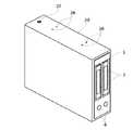
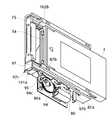
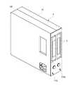
先ず、本発明の第1の実施の形態を説明する。第1の実施の形態では、先ず始めに情報処理装置としてのパーソナルコンピュータの概略について説明する。図1は第1の実施の形態に係るパーソナルコンピュータ1を左前斜め上から見た斜視図、図2はパーソナルコンピュータ1を左斜め下から見た斜視図である。
【0009】
図1において、パーソナルコンピュータ1はケース2により覆われており、パーソナルコンピュータ1には、パーソナルコンピュータ1から取り外し可能なディスクユニット5が装着されている。ディスクユニット5はパーソナルコンピュータ1の前面から取り外しが可能である。更に、ディスクユニット5には、ディスクユニット5から取り外し可能な同一機種のリムーバブルハードディスク3が例えば2台装着されている。2台のリムーバブルハードディスク3はディスクユニット5の前面から取り外しが可能である。
【0010】
ディスクユニット5の前面には、2台のリムーバブルハードディスク3のイジェクトを各々指示するためのスイッチ6、6も設けられている。また、パーソナルコンピュータ1の前面には、USB(Universal Serial Bus)コネクタ7、PCカード8が挿入されたPCカードスロット9、IEEE(Institute of Electrical and Electronics Engineers)1394コネクタ10、S端子コネクタ11、映像端子12、音声端子14、LAN(Local Area Network)コネクタ15、電源スイッチ16等も設けられている。
【0011】
図2において、パーソナルコンピュータ1の下面には、大形状の凹部17が設けられている。凹部17には、LANコネクタ18が例えば4個と2段タイプのUSBコネクタ13が設けられており、更に電源コネクタも設けられている。また、凹部17には、電源ケーブルやLANケーブル等のケーブル類を通す切り欠き部19も設けられている。なお、本実施の形態のパーソナルコンピュータ1には、データ入力・指示用のキーボードやマウス等の入力装置、ディスプレイ等の表示装置等も接続されているが、図示を省略する。
【0012】
図3は上記図1、図2で示したディスクユニット5に装着された2台のリムーバブルハードディスク3、3のうち左側のリムーバブルハードディスク3がイジェクトされた状態を示す斜視図である。図3に示すように、リムーバブルハードディスク3は自動的にイジェクト可能な機構を有しており、図3では左側のリムーバブルハードディスク3のみイジェクトされているが、右側のリムーバブルハードディスク3も同様にイジェクト可能である。イジェクト機構の詳細については後ほど説明する。
図4は上記図1、図2で示したディスクユニット5がパーソナルコンピュータ1からイジェクトされた状態を示す斜視図である。図4に示すように、本実施の形態のパーソナルコンピュータ1では、ユーザがドライバ等の工具を使用しなくても、後述のイジェクト機構により簡単にディスクユニット5を取り外せる構造となっている。
【0013】
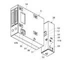
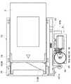
図5はパーソナルコンピュータ1の内部構造を左前斜め下から見た斜視図である。ディスクユニット5はユニットシャーシ20に挿入されている。ディスクユニット5の下部には電源21が設けられ、電源21の下面には電源コネクタ22が設けられている。また、電源21の下方にはバッテリ23が設けられている。上記図1、図2で示した各種のコネクタ類はマザーボード24にはんだ付けされており、また、マザーボード24には各種の拡張ボード25も接続されている。なお、ユニットシャーシ20、電源21、バッテリ23、マザーボード24等は不図示のシャーシ等に固定されている。
【0014】
<ディスクユニット、コネクタユニットの構成>
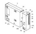
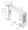
続いて、ディスクユニット5及びコネクタユニット28に関して説明する。図6はディスクユニット5がユニットシャーシ20に挿入された状態を左前斜め上方向から見た斜視図であり、図7は図6と同一状態の構成を右後ろ斜め下から見た斜視図である。図6、図7においてユニットシャーシ20の上下両面には、パーソナルコンピュータ本体のシャーシと固定するためのねじ穴26がそれぞれ例えば4個づつ設けられている。また、ユニットシャーシ20の上下両面に示されているねじ27は、後ほど説明するコネクタユニット28をユニットシャーシ20に固定している。
【0015】
図8、図9は上記図6、図7の状態からユニットシャーシ20を取り除いた状態を示す図である。ディスクユニット5はコネクタユニット28と結合状態にある。ディスクユニット5は左右両面及び背面をカバー30、31により覆われ、前面はフロントカバー32により覆われている。カバー30には凹部33が、カバー31には凹部34が各々設けられ、ディスクユニット5がパーソナルコンピュータ1から取り外された際にユーザが持ち易い構造となっている。更に、カバー31には例えば4箇所の凹部41が設けられている。凹部41に現れている4本のねじ40は、後ほど説明するリムーバブルハードディスク3のイジェクトユニットをカバー31に固定している。更に、ディスクユニット5のカバー30、31にはそれぞれ、イジェクト穴35、36、故障表示穴37、38も設けられている。これらの穴の機能に関しては後ほど説明する。
【0016】
コネクタユニット28はカバー43とベース44により覆われ、コネクタユニット28の背面にはコネクタ45が露出している。コネクタ45は不図示のコネクタケーブルによりマザーボード24(図5参照)に電気的に接続されている。コネクタユニット28のカバー43の上下両面にはねじ穴46が設けてあり、上記図6、図7で示したように、コネクタユニット28はねじ穴46に貫通させたねじ27によってユニットシャーシ20に固定されている。また、カバー43の上下両面には角穴47が設けてあり、ベース44に一体に設けられたツメ48と嵌合している。
【0017】
即ち、本実施の形態のパーソナルコンピュータ1は、パーソナルコンピュータ本体に固定されるコネクタユニット28と、パーソナルコンピュータ本体から取り外し可能なディスクユニット5を備え、コネクタユニット28とディスクユニット5は電気的に接続可能で、ディスクユニット5には取り外し可能なリムーバブルハードディスク3が電気的に接続可能であり、ディスクユニット5はリムーバブルハードディスク3の動作中はコネクタユニット28から取り外しできない構造を有し、リムーバブルハードディスク3はその動作中はディスクユニット5から取り外しできない構造を有する、という特徴を備えている。
【0018】
<ディスクユニットのロック機構とイジェクト機構>
次に、ディスクユニット5のロック機構とイジェクト機構に関して説明する。図10はディスクユニット5がコネクタユニット28と結合した状態を上から見た平面図、図11は図10のA−A線に沿う断面図である。図12〜図17はディスクユニット5がコネクタユニット28からイジェクトされた状態を様々な方向から見た図であり、上記説明した図4の状態を表している。図12はイジェクト状態を上から見た平面図、図13は図12のB−B線に沿う断面図、図14はイジェクト状態を右後ろ斜め上から見た斜視図、図15はイジェクト状態を右前斜め下から見た斜視図、図16はイジェクト状態を左前斜め上からから見た斜視図、図17はイジェクト状態を左後ろ斜め下から見た斜視図である。
【0019】
始めに、ディスクユニット5のロック機構とイジェクト機構の概要について説明する。図10、図11において、ディスクユニット5をイジェクトするためのイジェクトレバー51はコネクタユニット28側に収納され、非イジェクト状態となっている。ロックツメ52は図14に示すディスクユニット5のカバー31に設けられた角穴68に係合することで、ディスクユニット5をコネクタユニット28にロックした状態となっている。また、コネクタユニット28に設けられたコネクタ50は、ディスクユニット5に設けられたコネクタ55と電気的接続状態にある。
【0020】
図12、図13に示すように、ロックツメ52が軸56を回転中心として矢印K方向に僅かに回転し、上記カバー31に設けられた角穴68からロックツメ52が外れ、ディスクユニット5とコネクタユニット28のロックが解除される。それと共に、イジェクトレバー51が軸56を回転中心として矢印K方向に僅かに回転し、図15、図16に示すコネクタユニット28の角穴53からイジェクトレバー51が飛び出し、図14、図17に示すように、イジェクトレバー51でディスクユニット5のカバー31を押し出すことでディスクユニット5をイジェクトする。この際、コネクタ50とコネクタ55の接続も当然解除される。このように、ディスクユニット5のロック機構とイジェクト機構は、ほとんどコネクタユニット28側に設けてある。これにより、ディスクユニット5の不用意な引き抜き操作を防止可能である。
【0021】
次に、ディスクユニット5のロック機構とイジェクト機構の詳細について説明する。図11、図13において、コネクタユニット28における軸56、軸57、軸58はケース43にカシメられ、スイッチ61はねじ62によりケース43に固定されている。モータ59はケース43の曲げ起こし部69にねじ60により固定されている。また、ケース43にはストッパ29も一体に形成され、ねじりコイルばね63の一端が付勢されている。
【0022】
図18〜図23はカバー43を不図示としたコネクタユニット28を示す図である。図18はコネクタユニット28におけるディスクユニット5との接続時の状態を右方向から見た側面図、図19はコネクタユニット28を右前斜め下から見た斜視図、図20はコネクタユニット28を左前斜め下から見た斜視図である。図21はコネクタユニット28がディスクユニット5をイジェクトした状態を右方向から見た側面図、図22はコネクタユニット28を右前斜め下から見た斜視図、図23はコネクタユニット28を左前斜め下から見た斜視図である。
【0023】
図18、図19、図20において、コネクタユニット28のコネクタ55とコネクタ45はサブ基板70にはんだ付けされ、サブ基板70はねじ71によりベース44に固定されている。モータ59は不図示のリード線によりサブ基板44に電気的に接続されている。また、モータ59にはウォームギヤ64が圧入され、ウォームギヤ64は軸58に回転自在に挿入された二段ギヤであるギヤ65の一方のギヤと噛合している。ギヤ65のもう一方のギヤは軸57に挿入されたギヤ66と噛合している。ギヤ66にはカム66a、カム66b、カム66cが一体に設けられている。スイッチ62は不図示のリード線によりサブ基板70に電気的に接続されている。スイッチ62の押しボタン62aはカム66cの凸部により押されており、スイッチ62はON状態となっている。
【0024】
ねじりコイルばね63はロックツメ52に挿入され、該ばね63の一端はロックツメ52の凸部52aに付勢し、該ばね63の他端は上述したようにカバー43に設けられたストッパ29(図11参照)に付勢されている。従って、ロックツメ52は軸56を中心に矢印C方向に力を受けており、カム66bの凹凸により揺動する。コネクタユニット28に対するディスクユニット5の挿入時、ロックツメ52の斜面部52bは、図14に示す角穴68の縁68aにより押され、ロックツメ52は矢印K方向に回転するが、ディスクユニット5がコネクタユニット28に完全に結合した状態では、角穴68に斜面部52bが入り込み、ロックツメ52は矢印C方向に回転し、ディスクユニット5とコネクタユニット28がロック状態となる。
【0025】
イジェクトレバー51は軸56に挿入され、上述したように、イジェクトレバー51の一方の端51aはディスクユニット5のイジェクト時にディスクユニット5のケース31の背面を押すが(図13参照)、イジェクトレバー51の他方の端はカム66aに接し、カム66aの凹凸により揺動する。本実施の形態では、カム66aの凸部がイジェクトレバー51の他方の端に接しているとき、イジェクトレバー51は矢印K方向に回転し、ディスクユニット5をイジェクトする。
【0026】
図21、図22、図23はディスクユニット5のイジェクト時におけるコネクタユニット28の内部状態を示す図であり、図21はコネクタユニット28を右方向から見た側面図、図20はコネクタユニット28を右前斜め下から見た斜視図、図21はコネクタユニット28を左前斜め下から見た斜視図である。
【0027】
図21、図22、図23において、ギヤ66は上記図18の状態から矢印D方向へ180度回転した状態となっており、スイッチ62の押しボタン62aはカム66cの凸部にないためフリーとなり、スイッチ62はOFF状態となっている。ロックツメ52の基端部はカム66bの凸部に接しているため、矢印K方向に回転し、非ロック状態となっている。また、イジェクトレバー51はカム66aの凸部に接し、矢印K方向に回転し、ディスクユニット5をイジェクトする状態となっている。
【0028】
実際の動作としては、ディスクユニット5のイジェクト命令(ロック解除命令)が発せられると、ギヤ66が矢印D方向に回転するようにモータ59が回転し、始めにスイッチ62がOFF状態となり、ロックツメ52が矢印C方向と逆に回転し、非ロック状態となる。次に、イジェクトレバー51が矢印K方向に回転し、ディスクユニット5をイジェクトする。そのままモータ59は回転し続け、ロックツメ52が矢印C方向に回転し、初期状態に戻る。更に、スイッチ62がON状態となり、モータ59が停止し、ディスクユニット5のイジェクト動作(排出動作)が終了する。この時、イジェクトレバー51はディスクユニット5をイジェクトした状態となっているが、カム66aの凹部と対応する位置にあるため、再び、ディスクユニット5がコネクタユニット28へ装着される際に、コネクタユニット28内へ収納される。
【0029】
なお、ディスクユニット5に対するイジェクト命令は後ほど説明するパーソナルコンピュータ1のCPU110から発せられるが、ディスクユニット5内の2台のリムーバブルハードディスク3が非アクセス状態になっていることをCPU110が判断してから行われる。従って、ユーザがパーソナルコンピュータ1に装備されたキーボード等の入力手段の操作により、ディスクユニット5をイジェクトしようとしても、2台のリムーバブルハードディスク3のどちらか一方でもアクセス状態にある場合はイジェクトできないシステムとなっている。
【0030】
<リムーバブルハードディスクのイジェクト機構>
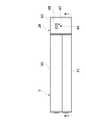
次に、ディスクユニット5(5インチ型ディスク)の内部の構成とリムーバブルハードディスク3のイジェクト機構の概略について説明する。図24、図25、図26はディスクユニット5の内部を示す図であり、図24はディスクユニット5を右方向から見た側面図、図25はディスクユニット5を右後ろ斜め下から見た斜視図、図26はディスクユニット5を左前斜め上から見た斜視図である。
【0031】
図24、図25、図26において、72、73はディスクユニット5内から2台のリムーバブルハードディスク3を各々イジェクトするためのイジェクトユニットであり、ほぼ左右対称形状をしている。イジェクトユニット72、73は上記図9で示したように、4本のねじ40によりケース31に固定されている。また、イジェクトユニット72、73には各々コネクタ75、76が固定され、コネクタ75、76はフレキシブルプリント板74にはんだ付けされている。更に、コネクタ75、76はリムーバブルハードディスク3のコネクタ3aに電気的に接続されている。フレキシブルプリント板74にはコネクタ55もはんだ付けされ、更に、コネクタ55は上記図17で示したように、ねじ77によりケース31に固定されている。
【0032】
また、78、79は2台のリムーバブルハードディスク3を各々イジェクトするための駆動ユニットであり、イジェクトユニット72、73に各々対応している。駆動ユニット78、79に各々設けられた、モータ80、81、スイッチ82、83は、不図示のリード線によりフレキシブルプリント板74に電気的に接続されている。更に、上記図1、図2で示したリムーバブルハードディスク3のイジェクトを指示するためのスイッチ6も、不図示のリード線によりフレキシブルプリント板74に電気的に接続されている。
【0033】
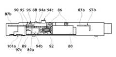
続いて、リムーバブルハードディスク3のイジェクト機構の詳細について説明する。上述したように、イジェクトユニット72、73はほぼ左右対象形状となっているため、左側のユニット、即ち、イジェクトユニット72を例に挙げ動作を説明する。図27、図28、図29、図30はイジェクトユニット72にリムーバブルハードディスク3が装着された状態を示す図であり、図27は装着状態を左方向から見た側面図、図28は装着状態を右方向から見た側面図、図29は装着状態を下方向から見た平面図、図30は装着状態を左前斜め下から見た斜視図である。
【0034】
図27、図28、図29、図30において、駆動ユニット78のベース85はねじ86により、リムーバブルハードディスク3が装着されているソケット87に固定されている。ベース85には、ねじ90によりスイッチ89が固定されると共に、ねじ91によりモータ80が固定されている。モータ80はパルスモータを使用している。更に、ベース85には軸85a、軸88も固定されている。モータ80にはウォームギヤ92が圧入され、ウォームギヤ92は軸85aに回転自在に挿入されたギヤ93と噛合している。
【0035】
ギヤ93は二段ギヤとなっており、ギヤ93を構成する二段ギヤのうち、ウォームギヤ92と噛合していないギヤは、軸88に回転自在に挿入されたギヤ94と噛合している。ギヤ94の両面にはカム94a、94bが配設され、スラスト方向の規制はEリング98によって行われている。なお、図29では、カム94bの凸部がスイッチ89の押しボタン部89aを押している状態になっており、スイッチ89はON状態となっている。
【0036】
ソケット87の下方に設けられたレバー97は、ソケット87に設けられた溝87a、87b等に沿って動く。また、レバー97には軸96が固定されている。軸96にはローラ95が回転自在に挿入され、ローラ95はEリング99によってスラスト方向の規制を受けている。ローラ95はカム94aのカム面に接しており、カム94aの凹凸によりレバー97が移動する。図28に示すように、レバー97には曲げ起こし部97aが設けられ、ばね98の一方が挿入されている。ばね98のもう一方はソケット87に設けられた軸87cに挿入されている。そのため、ローラ95は常にカム94aのカム面に押し付けされている。
【0037】
更に、図28に示すように、ソケット87には軸100が圧入され、軸100にはアーム101が挿入されている。アーム101の抜け止めとしてはEリング99が軸100に装着されている。アーム101の端部には凸部101aが形成され、凸部101aはレバー97に設けられた凹部97cと係合している。イジェクト部材102はソケット87に設けられた不図示の溝に沿い、矢印E方向に移動する。アーム101のカム面101bはイジェクト部材102の折り曲げ部102aと接しており、アーム101が矢印F方向に回転することにより、イジェクト部材102は矢印E方向へ移動する。
【0038】
<リムーバブルハードディスクのイジェクト動作>
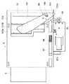
続いて、リムーバブルハードディスク3のイジェクト動作を説明する。図31、図32、図33、図34、図35はイジェクトユニット72からリムーバブルハードディスク3がイジェクトされた状態を示す図であり、図31はイジェクト状態を左方向から見た側面図、図32はイジェクト状態を右方向から見た側面図、図33はイジェクト状態を下から見た平面図、図34は図33のG−G線に沿う断面図、図35はイジェクト状態を左後部斜め下から見た斜視図である。
【0039】
図31、図32、図33、図34、図35に示すように、モータ80の回転によりギヤ94が180度回転し、カム94aがローラ95を押し下げ、それに伴いレバー97も押し下げられ、レバー97の凹部97cと係合したアーム101の凸部101aも押し下げられる。アーム101は矢印F方向に回転し、イジェクト部材102を矢印E方向へ移動させる。イジェクト部材102には上記曲げ起こし部102bが設けられており、曲げ起こし部102bによる押圧動作によりリムーバブルハードディスク3を排出する。図33、図34に示すように、このとき、スイッチ89はOFF状態となっている。
【0040】
実際の動作としては、ディスクユニット5に装着された2台のリムーバブルハードディスク3、3のうち、例えば左側のリムーバブルハードディスク3に対するイジェクト命令が、パーソナルコンピュータ1のCPU110(図39参照)から発せられると、ギヤ94は180度回転したところで停止することはなく、そのまま回転し続け、スイッチ89がONとなった後、所定量回転したところで停止し、一連の動作を終了する。
【0041】
なお、左側のリムーバブルハードディスク3に対するイジェクト命令は、上述したようにパーソナルコンピュータ1のCPU110から発せられるが、CPU110で左側のリムーバブルハードディスク3が非アクセス状態になっていることを判断して行われる。従って、ユーザがパーソナルコンピュータ1に装備されたキーボード等の入力手段を操作したり、ディスクユニット6前面のスイッチ6を押下することにより、パーソナルコンピュータ1からディスクユニット5をイジェクトしようとしても、左側のリムーバブルハードディスク3がアクセス状態では自動的にイジェクトできない。
【0042】
また、上記図1、図2等で示したように、リムーバブルハードディスク3は、ディスクユニット5への装着状態ではディスクユニット5のフロントカバー32表面より凹んでいるので、ディスクユニット5がパーソナルコンピュータ1に装着された状態では、リムーバブルハードディスク3をディスクユニット5から無理矢理引き抜くことはできない。しかし、本実施の形態では、ディスクユニット5に装着されたリムーバブルハードディスク3は、ディスクユニット5がパーソナルコンピュータ1から外された状態では、ディスクユニット5から手動でイジェクトできる工夫がしてある。次に、この機構について説明する。
【0043】
図36はディスクユニット5から手動でリムーバブルハードディスク3を外した状態のイジェクトユニット72を左方向から見た側面図である。図27、図31に示したように、通常、レバー97はカム94aの凹凸に連動して動くが、図27に示す状態から図28に示す状態のままで、ばね98を圧縮する方向へ力を加えると、レバー97は矢印H方向に移動できる。レバー97には曲げ部97bが一体に設けられているため、図27の状態から曲げ部97bを矢印H方向へ押すと、図36の状態となり、リムーバブルハードディスク3は排出される。
【0044】
一方、図8、図9、図13等に示したように、カバー30、カバー31には曲げ部97bの位置に対応したイジェクト穴35、36が設けられている。従って、パーソナルコンピュータ1からディスクユニット5を取り外した状態では、イジェクト穴35、36を介して曲げ部97bをばね98を圧縮する方向へ押すことにより、リムーバブルハードディスク3をディスクユニット5から手動でイジェクトすることができる。
【0045】
また、上記のようにパーソナルコンピュータ1からディスクユニット5を取り外した状態では、リムーバブルハードディスク3への電気的なアクセスは当然遮断されているため、リムーバブルハードディスク3をディスクユニット5から安全にイジェクトすることができる。また、何らかの故障によりリムーバブルハードディスク3をディスクユニット5から自動でイジェクトできなくなった場合でも、ディスクユニット5をパーソナルコンピュータ1から外すことにより、リムーバブルハードディスク3をディスクユニット5から手動でイジェクトすることが可能となる。
【0046】
一方、本実施の形態では、上述したようにリムーバブルハードディスク3が2台使用されている。万が一どちらか一方のリムーバブルハードディスク3が故障した場合、ユーザはパーソナルコンピュータ1に装備されたCRT等のディスプレイ上では「Cドライブの故障」又は「Dドライブの故障」等の表示でどちらのリムーバブルハードディスク3が故障したかを知ることができる。しかし、故障したリムーバブルハードディスク3を交換しようとした際、左右どちらのリムーバブルハードディスク3がCドライブで、どちらがDドライブかを判別できないことがある。そこで、本実施の形態では、故障したリムーバブルハードディスク3がどちらか明らかになるような下記の表示をほとんどコストをかけずに実現している。
【0047】
<リムーバブルハードディスクの故障時の表示>
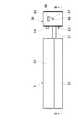
次に、例えば左側のリムーバブルハードディスク3が故障した際の動作について説明する。図37、図38は左側のリムーバブルハードディスク3が故障した状態を左方向から見た側面図であり、図37はリムーバブルハードディスク3のイジェクトユニット72を示す側面図、図38はディスクユニット5を示す側面図である。
【0048】
左側のリムーバブルハードディスク3が故障すると、パーソナルコンピュータ1のCPU110が故障を検知し、CPU110はギヤ94が矢印J方向に45度回転するようにモータ80に回転命令を発し、モータ80の回転によりギヤ94が45度回転する。その状態を示したものが図37である。図37において、カム94aの上面には円筒状の凸部94cが形成され、凸部94の上面にはのこぎり状の細かい凹凸が形成されている。図38はイジェクトユニット72が図37の状態でのディスクユニット5を示しており、故障表示穴37には凸部94cが表示されている。即ち、故障表示穴37を介した凸部94cの表示により、左側のリムーバブルハードディスク3が故障したことをユーザに明示する。
【0049】
また、左側のリムーバブルハードディスク3が故障すると、パーソナルコンピュータ1のCPU110がイジェクト命令を発し、イジェクトユニット72によりディスクユニット5からリムーバブルハードディスク3が自動的にイジェクトされる。
【0050】
本実施の形態では、左側のリムーバブルハードディスク3が故障した状態における故障表示を示したが、右側のリムーバブルハードディスク3が故障した状態における故障表示についても同様な構造となっている。上記図9等に示したように、ディスクユニット5の右側面にも故障表示穴38が設けてあり、上記図25等に示したように、イジェクトユニット73側にも同様に凸部94cが設けてある。従って、ユーザは故障表示穴37、38を見ることで、どちらのリムーバブルハードディスク3が故障しているのかを即座に判別することができる。本実施の形態では、凸部94cの形状をのこぎり状にしたが、凸部94の表面を目立つ色に着色したり、目立つ色のシールを貼っても良い。
【0051】
<パーソナルコンピュータの電気的構成>
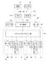
次に、パーソナルコンピュータ1の電気的構成の概要をブロック図を用いて説明する。図39はパーソナルコンピュータ1の電気的構成の概略を示すブロック図である。パーソナルコンピュータ1は、電源21、バッテリ23、マザーボード24、コネクタユニット28、ディスクユニット5、キーボードやマウス等の入力装置、ディスプレイ等の表示装置(以上図示略)を備えている。
【0052】
マザーボード24は、CPU110、ROM111を備え、コネクタユニット28は、モータ59、スイッチ61、サブ基板70を備え、ディスク5は、フレキシブルプリント板74、右側のリムーバブルハードディスク3、右側用のイジェクトユニット72、右側用のスイッチ6、左側のリムーバブルハードディスク3、左側用のイジェクトユニット73、左側用のスイッチ6を備えている。更に、イジェクトユニット72は、モータ80、スイッチ82を備え、イジェクトユニット73は、モータ81、スイッチ83を備えている。
【0053】
電源21はマザーボード24とバッテリ23へ電源を供給する。バッテリ23は所謂無停電電源であり、パーソナルコンピュータ1が動作中に停電や電源コンセントを抜かれた場合、一時的にマザーボード24へ電源を供給することができる。そのため、パーソナルコンピュータ1が動作中に停電等が発生しても、正常処理後、パーソナルコンピュータ1が停止するので、停電等によるデータの破壊等は発生しない。
【0054】
マザーボード24にはCPU110が搭載され、パーソナルコンピュータ1の頭脳として様々な判断を行っている。CPU110は、イジェクト命令を発することにより、コネクタユニット28からのディスクユニット5のイジェクト、ディスクユニット5からのリムーバブルハードディスク3のイジェクトを制御すると共に、リムーバブルハードディスク3に対するデータの書き込み及び読み出しを行う。また、本実施の形態では、OS(オペレーティングシステム)がマザーボード24のROM111に書き込まれており、ディスクユニット5からリムーバブルハードディスク3が外された状態でも、様々な処理を行うことが可能となっている。
【0055】
コネクタユニット28内に設けられたサブ基板70は、マザーボード24から電源の供給を受け、また、マザーボード24との間でデータの授受も行っている。また、サブ基板70には、ディスクユニット5をパーソナルコンピュータ1からイジェクトするための駆動源であるモータ59と、モータ59の回転制御のためのスイッチ61も接続されている。
【0056】
ディスクユニット5内に設けられたフレキシブルプリント板74は、サブ基板70から電源の供給を受け、また、サブ基板70との間でデータの授受も行っている。フレキシブルプリント板74には、取り外し可能な記憶装置である2台のリムーバブルハードディスク3、該リムーバブルハードディスク3のイジェクト用のモータ80、81、スイッチ82、83が接続されている。また、フレキシブルプリント板74には、リムーバブルハードディスク3のイジェクト指示用のスイッチ6も接続されている。
【0057】
上記の構成において、パーソナルコンピュータ1のCPU110は、上述したロック解除命令、取り外し命令の出力、ディスクユニット5のロック機構及びイジェクト機構を駆動するモータ59、リムーバブルハードディスク3のイジェクトユニットを駆動するモータ80、81の動作制御、リムーバブルハードディスク3に対するデータの書き込み及び読み出しを行う。
【0058】
以上説明したように、第1の実施の形態によれば、パーソナルコンピュータ1に固定されるコネクタユニット28と、パーソナルコンピュータ1から取り外し可能なディスクユニット5とを備え、コネクタユニット28とディスクユニット5は電気的に接続可能で、ディスクユニット5には取り外し可能なリムーバブルハードディスク3が電気的に接続可能であり、ディスクユニット5は、リムーバブルハードディスク3の動作中はコネクタユニット28から取り外しできない構造を有し、リムーバブルハードディスク3は、リムーバブルハードディスク3の動作中はディスクユニット5から取り外しできない構造を有するため、従来の如く、ハードディスク等の電子機器の動作中に電子機器が取り外されトラブルを引き起こす恐れを解消できると共に、簡単な構成でフレキシブルなパーソナルコンピュータ等の情報処理装置を構成することができる。
【0059】
また、リムーバブルハードディスク3は、ディスクユニット5がコネクタユニット28から取り外された状態ではディスクユニット5から取り外し可能な構造を有するため、安全にリムーバブルハードディスク3の交換等を行うことができる。
【0060】
また、ディスクユニット5は、コネクタユニット28に接続された状態ではパーソナルコンピュータ1の内部に隠れ、コネクタユニット28から取り外された状態では外部に表れる凹部33、34を備えるため、ディスクユニット5を取り外した際に持ち易く、使い勝手を向上させることができる。
【0061】
また、コネクタユニット28に対するディスクユニット5の接続に伴い両ユニット間をロック状態とし、イジェクト命令(ロック解除命令)に基づきロック状態を解除するロック機構(ロックツメ52、角穴68)を備えるため、コネクタユニット28からディスクユニット5が不用意に取り外される操作を防止することができる。
【0062】
また、コネクタユニット28に対するディスクユニット5の接続状態において、イジェクト命令に基づきディスクユニット5をコネクタユニット28からイジェクトするイジェクト機構(イジェクトレバー51)を備えるため、上記と同様に不用意に取り外される操作を防止することができる。
【0063】
また、ディスクユニット5のロック機構とイジェクト機構は一つの駆動原(モータ59)により駆動されるため、部品点数を増加させることなく、ロック機構とイジェクト機構を実現することができる。
【0064】
また、リムーバブルハードディスク3は、ディスクユニット5に対し複数台装着可能であるため、フレキシブルなパーソナルコンピュータ等の情報処理装置を構成することができる。
【0065】
また、ディスクユニット5に装着された複数台のリムーバブルハードディスク3のうち、非動作状態のリムーバブルハードディスク3を取出し可能であるため、安全にリムーバブルハードディスク3の交換等を行うことができる。
【0066】
また、ディスクユニット5は、ディスクユニット5に装着された複数台の何れかのリムーバブルハードディスク3の故障時に、どのリムーバブルハードディスク3が故障しているかを表示する表示手段(故障表示穴37、38、凸部94c)を備え、ディスクユニット5がコネクタユニット28から取り外された状態でも前記表示を保持するため、ユーザはどのリムーバブルハードディスク3が故障しているかを即座に判別することができる。
【0067】
また、ディスクユニット5に装着された複数台のリムーバブルハードディスク3は、リムーバブルハードディスク3をディスクユニット5からイジェクト可能なイジェクト機構(イジェクトユニット72、73)をそれぞれ備え、当該リムーバブルハードディスク3の故障時に、当該リムーバブルハードディスク3のイジェクトユニットは、故障した当該リムーバブルハードディスク3をディスクユニット5からイジェクトするため、故障したリムーバブルハードディスク3を手動で取り外す手間が省け、使い勝手を向上させることができる。
【0068】
また、リムーバブルハードディスク3のイジェクトユニットを駆動する第二の駆動源(モータ80、81)を備え、故障表示穴による表示を第二の駆動源を利用して行うため、部品点数を増加させることなく、リムーバブルハードディスク3の故障表示を行うことができる。
【0069】
また、リムーバブルハードディスク3は、ディスクユニット5に対しディスクユニット5の装着面より凹んだ状態で装着されるため、リムーバブルハードディスク3を無理矢理引き抜く操作を防止することができる。
【0070】
[第2の実施の形態]
次に、本発明の第2の実施の形態を説明する。上記第1の実施の形態では、リムーバブルハードディスク3の故障時の対応方法として、ディスクユニット5に設けた故障表示穴37、38により故障を表示したが、故障時の対応方法は上述した方法に限定されるものではない。例えば、パーソナルコンピュータ1のCPU110がリムーバブルハードディスク3の故障を検知すると、故障したリムーバブルハードディスク3をイジェクトするようイジェクト命令を出し、実際に故障したリムーバブルハードディスク3をイジェクト機構でイジェクトする構成としても構わない。
【0071】
[第3の実施の形態]
次に、本発明の第3の実施の形態を説明する。上記第1の実施の形態では、ディスクユニット5にはリムーバブルハードディスク3を2台装着可能な構造としたが、リムーバブルハードディスク3の装着台数は2台に限定されるものではなく、リムーバブルハードディスク3を1台以上任意台数装着できるようにしても構わない。また、ディスクユニット5から取り外し可能な電子機器はリムーバブルハードディスクだけに限定されるものではなく、例えば、CD−RWやDVDのユニットでも構わないし、それらの組み合わせでも構わない。
【0072】
[第4の実施の形態]
次に、本発明の第4の実施の形態を説明する。上記第1の実施の形態では、リムーバブルハードディスク3が故障した際の表示方法として、上記図37、図38に示したように、故障したリムーバブルハードディスク3側のカム94aを矢印J方向に45度回転し、ディスクユニット5側面の故障表示穴37から状態を確認できるようにしたが、第4の実施の形態としては、ディスクユニット5の前面から故障表示が確認できる構造を提案する。
【0073】
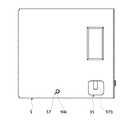
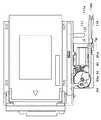
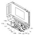
図40、図41は第4の実施の形態のディスクユニット5を示す図であり、図40はディスクユニット5を前方向から見た正面図、図41はディスクユニット5を左前斜め上から見た斜視図である。図42〜図45はディスクユニット5の内部を示す図であり、図42はディスクユニット内部を前方向から見た正面図、図43はディスクユニット内部を左方向から見た側面図、図44はディスクユニット内部を左前斜め下から見た斜視図、図45はディスクユニット内部を右前斜め下から見た斜視図である。なお、図40〜図45で説明する部品の符号は、上記第1の実施の形態で説明した部品とほぼ同様な部品については同一の符号を用いている。
【0074】
図40、図41において、ディスクユニット5のフロントカバー32には、故障表示穴115、116が2台のリムーバブルハードディスク3に各々対応させた状態で設けてあり、図示例では左側のリムーバブルハードディスク3が故障した状態を表している。図40に示すように、左側の故障表示穴115には丸い凸部117aが見えている。
【0075】
次に、ディスクユニット5の内部の構造について説明する。ディスクユニット5における左右のイジェクトユニット72、73はほぼ対象形状のため、本実施の形態では主に左側のイジェクトユニット72に関して説明する。図42〜図45において、左側のイジェクトユニット72のベース85には軸122が固定され、軸122にはレバー117が回転自在に挿入され、レバー117の先端部には円柱状の凸部117aが設けてある。
【0076】
また、軸122にはばね120も挿入され、ばね120の一端はベース85の曲げお起こし部85aに付勢され、他端はレバー117の凸部117bに付勢されている。このため、レバー117は矢印L方向へ力を受けている。また、レバー117はカム94aに接しているが、モータ80の回転によりカム94aが回転し、レバー117がカム94aのカム面から外れた場合は、レバー117はカバー30(図41参照)の内面で回転規制を受ける。また、レバー117のスラスト方向左側の規制もカバー30の内面により行われている。
【0077】
左側のイジェクトユニット72のカム94aは、右側のイジェクトユニット73のカム125aに比べ矢印J方向に45度回転した状態となっている。また、左側のイジェクトユニット72のレバー117は、右側のイジェクトユニット73のレバー118に比べ矢印M方向に5度回転し、凸部117aが故障表示穴115から目視可能な位置にある。従って、上記第1の実施の形態と同様に、リムーバブルハードディスク3が故障した際、パーソナルコンピュータ1のCPU110がそれを検知し、故障したリムーバブルハードディスク3側のイジェクトユニットのカムを45度回転させることにより、該当する故障表示穴に凸部を位置させることで、故障時の表示を行うことができる。
【0078】
[他の実施の形態]
上記実施の形態では、パーソナルコンピュータのディスクユニットに同一機種の複数台(上記例では2台)の電子機器(リムーバブルハードディスク)を着脱自在に装着する場合を例に挙げたが、本発明はこれに限定されるものではなく、ディスクユニット5に複数種の電子機器を着脱自在に装着する場合にも適用可能である。
【0079】
上記実施の形態では、情報処理装置をパーソナルコンピュータとした場合を例に挙げたが、本発明は特定の用途の情報処理装置に限定されるものではなく、パーソナルコンピュータ以外に、ワークステーションなど各種用途の情報処理装置に適用可能である。
【0080】
【発明の効果】
本発明によれば、電子機器の動作中に、電子機器に装着されたユニットが取り外されることにより発生する、電子機器のトラブルを防止することが出来る。
【図面の簡単な説明】
【図1】本発明の第1の実施の形態に係るパーソナルコンピュータを左前斜め上から見た斜視図である。
【図2】パーソナルコンピュータを左斜め下から見た斜視図である。
【図3】パーソナルコンピュータのリムーバブルハードディスクの左側がイジェクトされた状態を示す斜視図である。
【図4】パーソナルコンピュータのディスクユニットがイジェクトされた状態を示す斜視図である。
【図5】パーソナルコンピュータの内部構造を左前斜め下から見た斜視図である。
【図6】ディスクユニットがユニットシャーシに挿入された状態を左前斜め上方向から見た斜視図である。
【図7】図6と同一状態のディスクユニットを右後ろ斜め下から見た斜視図である。
【図8】図6の状態からユニットシャーシを取り除いた状態を示す斜視図である。
【図9】図7の状態からユニットシャーシを取り除いた状態を示す斜視図である。
【図10】ディスクユニットがコネクタユニットと結合した状態を上から見た平面図である。
【図11】図10のA−A線に沿う断面図である。
【図12】ディスクユニットがコネクタユニットからイジェクトされた状態を上から見た平面図である。
【図13】図12のB−B線に沿う断面図である。
【図14】ディスクユニットがコネクタユニットからイジェクトされた状態を右後ろ斜め上から見た斜視図である。
【図15】ディスクユニットがコネクタユニットからイジェクトされた状態を右前斜め下から見た斜視図である。
【図16】ディスクユニットがコネクタユニットからイジェクトされた状態を左前斜め上からから見た斜視図である。
【図17】ディスクユニットがコネクタユニットからイジェクトされた状態を左後ろ斜め下から見た斜視図である。
【図18】カバーを不図示とし、コネクタユニットをディスクユニットとの接続時状態を右方向から見た側面図である。
【図19】図18の状態のコネクタユニットを右前斜め下から見た斜視図である。
【図20】図18の状態のコネクタユニットを左前斜め下から見た斜視図である。
【図21】ディスクユニットを排出した状態のコネクタユニットを右方向から見た側面図である。
【図22】ディスクユニットを排出した状態のコネクタユニットを右前斜め下から見た斜視図である。
【図23】ディスクユニットを排出した状態のコネクタユニットを左前斜め下から見た斜視図である。
【図24】ディスクユニットの内部を右方向から見た側面図である。
【図25】ディスクユニットの内部を右後ろ斜め下から見た斜視図である。
【図26】ディスクユニットの内部を左前斜め上から見た斜視図である。
【図27】イジェクトユニットにリムーバブルハードディスクが装着された状態を左方向から見た側面図である。
【図28】イジェクトユニットにリムーバブルハードディスクが装着された状態を右方向から見た側面図である。
【図29】イジェクトユニットにリムーバブルハードディスクが装着された状態を下方向から見た平面図である。
【図30】イジェクトユニットにリムーバブルハードディスクが装着された状態を左前斜め下から見た斜視図である。
【図31】イジェクトユニットからリムーバブルハードディスクがイジェクトされた状態を左方向から見た側面図である。
【図32】イジェクトユニットからリムーバブルハードディスクがイジェクトされた状態を右方向から見た側面図である。
【図33】イジェクトユニットからリムーバブルハードディスクがイジェクトされた状態を下から見た平面図である。
【図34】図33のG−G線に沿う断面図である。
【図35】イジェクトユニットからリムーバブルハードディスクがイジェクトされた状態を左後部斜め下から見た斜視図である。
【図36】手動でリムーバブルハードディスクを外した状態のイジェクトユニットを左方向から見た側面図である。
【図37】左側のリムーバブルハードディスクが故障した状態のイジェクトユニットを左方向から見た側面図である。
【図38】左側のリムーバブルハードディスクが故障した状態のディスクユニットを左方向から見た側面図である。
【図39】パーソナルコンピュータの電気的概略構成を示すブロック図である。
【図40】本発明の第4の実施の形態に係るディスクユニットを前方向から見た正面図である。
【図41】ディスクユニットを左前斜め上から見た斜視図である。
【図42】ディスクユニットの内部を前方向から見た正面図である。
【図43】ディスクユニットの内部を左方向から見た側面図である。
【図44】ディスクユニットの内部を左前斜め下から見た斜視図である。
【図45】ディスクユニットの内部を右前斜め下から見た斜視図である。
【符号の説明】
1 パーソナルコンピュータ(電子機器)
3 リムーバブルハードディスク(着脱式電子機器)
5 ディスクユニット(装着ユニット)
28 コネクタユニット(コネクタユニット)
33、34 凹部(凹部)
37、38 故障表示穴(報知手段)
51 イジェクトレバー(第二の取り外し機構)
52 ロックツメ
59 モータ(第二の駆動部)
68 角穴
72、73 イジェクトユニット(第一の取り外し機構)
80、81 モータ(第一の駆動部)
94c 凸部(報知手段)
110 CPU(故障判別手段)
115、116 故障表示穴(報知手段)
117a、118a 凸部(報知手段)[0001]
BACKGROUND OF THE INVENTION
The present inventionElectronic equipment that can be attached and detachedAbout.
[0002]
[Prior art]
In recent years, with the spread of the Internet and e-mail, personal computers have been rapidly spread for accessing the Internet and sending / receiving e-mail, and for improving work efficiency in the office and sharing information. Is going on. On the other hand, manufacturers of personal computers have to produce a great number of models in order to respond to diversifying user needs. In addition, electronic devices such as hard disks and CD-ROM drives used in personal computers are progressing day by day and may quickly become obsolete. In view of this, a removable hard disk removable from a personal computer has been proposed, and an apparatus or the like in which electronic devices used in a personal computer are unitized and can be easily replaced by a user has been proposed.
[0003]
[Problems to be solved by the invention]
However, the above prior art has the following problems. When the unitized electronic device as described above is structured so that the user can easily remove it from the personal computer or replace it with another electronic device, for example, when the electronic device is a hard disk, the hard disk is operating during the operation of the hard disk. Has been removed from the personal computer, which can cause major trouble.
[0004]
The present invention has been made in view of the above points.,While the electronic device is in operationThe unit attached to the electronic deviceRemovedOf electronic equipmentTroublePreventThe purpose is to do.
[0005]
[Means for Solving the Problems]
The present invention relates to a detachable electronic device.WearingIn a possible electronic device, a connector unit arranged in the electronic device, and the connector unitWearingA mounting unit on which a detachable electronic device is mounted;A first removal mechanism for removing the removable electronic device from the mounting unit;Remove the mounting unit from the connector unitSecondA removal mechanism;A first drive unit for driving the first removal mechanism;SaidSecondDrive the removal mechanismSecondWhen the drive unit and the detachable electronic device attached to the attachment unit are in operation,In order to prevent the detachable electronic device from being removed by the first detaching mechanism, the mounting of the mounting unit and the detachable electronic device is fixed, and the mounting unit is removed by the second detaching mechanism. Locking mechanism for fixing mounting of the connector unit and the mounting unit so as to preventIt is characterized by having.
[0007]
DETAILED DESCRIPTION OF THE INVENTION
Hereinafter, embodiments of the present invention will be described in detail with reference to the drawings.
[0008]
[First Embodiment]
<Outline of personal computer>
First, a first embodiment of the present invention will be described. In the first embodiment, an outline of a personal computer as an information processing apparatus will be described first. FIG. 1 is a perspective view of the
[0009]
In FIG. 1, a
[0010]
On the front surface of the
[0011]
In FIG. 2, a large
[0012]
FIG. 3 is a perspective view showing a state in which the left removable
FIG. 4 is a perspective view showing a state in which the
[0013]
FIG. 5 is a perspective view of the internal structure of the
[0014]
<Configuration of disk unit and connector unit>
Next, the
[0015]
FIGS. 8 and 9 are views showing a state in which the
[0016]
The
[0017]
That is, the
[0018]
<Disk unit lock mechanism and eject mechanism>
Next, the lock mechanism and eject mechanism of the
[0019]
First, an outline of the lock mechanism and eject mechanism of the
[0020]
As shown in FIGS. 12 and 13, the
[0021]
Next, details of the lock mechanism and the eject mechanism of the
[0022]
18 to 23 show the
[0023]
18, 19, and 20, the
[0024]
The
[0025]
The
[0026]
21, 22, and 23 are views showing the internal state of the
[0027]
21, 22, and 23, the
[0028]
As an actual operation, when an eject command (unlock command) for the
[0029]
The eject command for the
[0030]
<Removable hard disk eject mechanism>
Next, an outline of the internal configuration of the disk unit 5 (5-inch disk) and the ejection mechanism of the removable
[0031]
In FIGS. 24, 25, and 26, 72 and 73 are eject units for ejecting two removable
[0032]
[0033]
Next, details of the ejection mechanism of the removable
[0034]
27, 28, 29, and 30, the
[0035]
The
[0036]
The
[0037]
Further, as shown in FIG. 28, the
[0038]
<Removable hard disk eject operation>
Next, the ejecting operation of the removable
[0039]
As shown in FIGS. 31, 32, 33, 34, and 35, the
[0040]
As an actual operation, when an ejection command is issued from the CPU 110 (see FIG. 39) of the
[0041]
Note that the eject command for the left removable
[0042]
As shown in FIGS. 1 and 2 and the like, the removable
[0043]
FIG. 36 is a side view of the
[0044]
On the other hand, as shown in FIG. 8, FIG. 9, FIG. 13, etc., the
[0045]
Further, in the state where the
[0046]
On the other hand, in this embodiment, two removable
[0047]
<Display when a removable hard disk fails>
Next, for example, an operation when the left removable
[0048]
If the left removable
[0049]
When the left removable
[0050]
In the present embodiment, the failure display when the left removable
[0051]
<Electrical configuration of personal computer>
Next, an outline of the electrical configuration of the
[0052]
The
[0053]
The
[0054]
The
[0055]
The
[0056]
The flexible printed
[0057]
In the above configuration, the
[0058]
As described above, according to the first embodiment, the
[0059]
Further, since the removable
[0060]
Further, since the
[0061]
In addition, since the
[0062]
In addition, since the
[0063]
Further, since the lock mechanism and the eject mechanism of the
[0064]
Since a plurality of removable
[0065]
In addition, since the non-operating removable
[0066]
Further, the
[0067]
The plurality of removable
[0068]
In addition, since the second drive source (
[0069]
Further, since the removable
[0070]
[Second Embodiment]
Next, a second embodiment of the present invention will be described. In the first embodiment, the failure is indicated by the failure display holes 37 and 38 provided in the
[0071]
[Third Embodiment]
Next, a third embodiment of the present invention will be described. In the first embodiment, the
[0072]
[Fourth Embodiment]
Next, a fourth embodiment of the present invention will be described. In the first embodiment, as a display method when the removable
[0073]
40 and 41 are views showing the
[0074]
40 and 41, the
[0075]
Next, the internal structure of the
[0076]
A
[0077]
The
[0078]
[Other embodiments]
In the above embodiment, a case where a plurality of electronic devices (removable hard disks) of the same model (removable hard disks) are detachably attached to the disk unit of the personal computer has been described as an example. The present invention is not limited, and the present invention is also applicable when a plurality of types of electronic devices are detachably mounted on the
[0079]
In the above-described embodiment, the case where the information processing apparatus is a personal computer has been described as an example. However, the present invention is not limited to the information processing apparatus for a specific application, and various applications such as a workstation other than the personal computer. It can be applied to other information processing apparatuses.
[0080]
【The invention's effect】
BookAccording to the inventionIn the operation of the electronic device, it is possible to prevent a trouble of the electronic device that occurs when the unit attached to the electronic device is removed.
[Brief description of the drawings]
FIG. 1 is a perspective view of a personal computer according to a first embodiment of the present invention when viewed obliquely from the upper left front.
FIG. 2 is a perspective view of the personal computer as viewed obliquely from the lower left.
FIG. 3 is a perspective view showing a state where the left side of the removable hard disk of the personal computer is ejected.
FIG. 4 is a perspective view showing a state where a disk unit of a personal computer is ejected.
FIG. 5 is a perspective view of the internal structure of the personal computer as viewed obliquely from the lower left front.
FIG. 6 is a perspective view of the state in which the disk unit is inserted into the unit chassis, as viewed from the upper left diagonal direction.
7 is a perspective view of the disk unit in the same state as FIG.
8 is a perspective view showing a state in which the unit chassis is removed from the state shown in FIG. 6. FIG.
9 is a perspective view showing a state in which the unit chassis is removed from the state shown in FIG.
FIG. 10 is a plan view of the state in which the disk unit is coupled to the connector unit as viewed from above.
11 is a cross-sectional view taken along line AA in FIG.
FIG. 12 is a plan view of a state in which the disk unit is ejected from the connector unit, as viewed from above.
13 is a cross-sectional view taken along line BB in FIG.
FIG. 14 is a perspective view of the state in which the disk unit is ejected from the connector unit, as viewed from the upper right rear obliquely.
FIG. 15 is a perspective view of a state in which the disk unit is ejected from the connector unit, as viewed obliquely from the lower right front.
FIG. 16 is a perspective view of a state in which the disk unit is ejected from the connector unit, as viewed obliquely from the upper left front.
FIG. 17 is a perspective view of the state in which the disk unit is ejected from the connector unit, as viewed obliquely from the lower left rear.
FIG. 18 is a side view of the state where the cover is not shown and the connector unit is connected to the disk unit as viewed from the right.
FIG. 19 is a perspective view of the connector unit in the state shown in FIG.
FIG. 20 is a perspective view of the connector unit in the state of FIG.
FIG. 21 is a side view of the connector unit in a state where the disk unit is ejected, as viewed from the right.
FIG. 22 is a perspective view of the connector unit in a state in which the disk unit is ejected, as viewed obliquely from the lower right front.
FIG. 23 is a perspective view of the connector unit in a state in which the disk unit is ejected, as viewed obliquely from the lower left front.
FIG. 24 is a side view of the inside of the disk unit as viewed from the right.
FIG. 25 is a perspective view of the inside of the disk unit as viewed from diagonally below the right rear.
FIG. 26 is a perspective view of the inside of the disk unit as viewed obliquely from the upper left front.
FIG. 27 is a side view of the state in which the removable hard disk is mounted on the eject unit as viewed from the left.
FIG. 28 is a side view of a state in which a removable hard disk is mounted on the eject unit, as viewed from the right.
FIG. 29 is a plan view of the state in which the removable hard disk is mounted on the eject unit as viewed from below.
FIG. 30 is a perspective view of the state in which the removable hard disk is mounted on the eject unit as viewed from the diagonally lower left front.
FIG. 31 is a side view of the state in which the removable hard disk is ejected from the eject unit as viewed from the left.
FIG. 32 is a side view of the state in which the removable hard disk is ejected from the eject unit as viewed from the right.
FIG. 33 is a plan view of the state in which the removable hard disk is ejected from the eject unit as seen from below.
34 is a cross-sectional view taken along the line GG in FIG. 33. FIG.
FIG. 35 is a perspective view of the state in which the removable hard disk is ejected from the eject unit, as viewed obliquely from the lower left rear.
FIG. 36 is a side view of the eject unit with the removable hard disk manually removed as viewed from the left.
FIG. 37 is a side view of the eject unit in a state in which the left removable hard disk has failed as viewed from the left.
FIG. 38 is a side view of the disk unit in a state where the left removable hard disk has failed, as viewed from the left.
FIG. 39 is a block diagram showing a schematic electrical configuration of a personal computer.
FIG. 40 is a front view of a disk unit according to a fourth embodiment of the present invention as viewed from the front.
FIG. 41 is a perspective view of the disk unit as seen from the upper left diagonally.
42 is a front view of the inside of the disk unit as seen from the front. FIG.
FIG. 43 is a side view of the inside of the disk unit as viewed from the left.
FIG. 44 is a perspective view of the inside of the disk unit as viewed obliquely from the lower left front.
FIG. 45 is a perspective view of the inside of the disk unit as viewed from diagonally below the right front.
[Explanation of symbols]
1 Personal computer (electronic equipment)
3 Removable hard disk (detachable electronic device)
5 Disc unit (mounting unit)
28 Connector unit (connector unit)
33, 34 Recess (recess)
37, 38 Fault display hole (notification means)
51 Eject lever (SecondRemoval mechanism)
52 Lock claw
59 Motor (SecondDrive part)
68 square hole
72, 73 Eject unit (FirstRemoval mechanism)
80, 81 motor(First drive unit)
94c Convex part (notification means)
110 CPU(lateDisability discrimination means)
115, 116 Failure display hole (notification means)
117a, 118a Convex part (notification means)
Claims (13)
Translated fromJapanese前記電子機器に配置されたコネクタユニットと、
前記コネクタユニットに装着可能であり、着脱式電子機器が装着される装着ユニットと、
前記装着ユニットから前記着脱式電子機器を取り外す第一の取り外し機構と、
前記コネクタユニットから前記装着ユニットを取り外す第二の取り外し機構と、
前記第一の取り外し機構を駆動させる第一の駆動部と、
前記第二の取り外し機構を駆動させる第二の駆動部と、
前記装着ユニットに装着された前記着脱式電子機器が稼動中である場合、前記第一の取り外し機構により前記着脱式電子機器が取り外されることを防止するように、前記装着ユニットと前記着脱式電子機器との装着を固定し、前記第二の取り外し機構により前記装着ユニットが取り外されることを防止するように、前記コネクタユニットと前記装着ユニットとの装着を固定するロック機構とを有することを特徴とする電子機器。In electronic devices that can beequipped with detachable electronic devices,
A connector unit disposed in the electronic device;
Amounting unit that can bemounted on the connector unit and on which a detachable electronic device is mounted;
A first removal mechanism for removing the removable electronic device from the mounting unit;
Asecond removal mechanism for removingthe mounting unit from the connector unit;
A first drive unit for driving the first removal mechanism;
Asecond drive unit for drivingthe second removal mechanism;
When the detachable electronic device attached to the attachment unit is in operation, the attachment unit and the detachable electronic device are prevented from being removed by the first removal mechanism. And a lock mechanism for fixing the attachment between the connector unit and the attachment unit so as to prevent the attachment unit from being removed by the second removal mechanism. Electronics.
前記故障判別手段において、前記着脱式電子機器が故障していると判別された場合、前記第一の取り外し機構は、故障していると判別された前記着脱式電子機器を排出することを特徴とする請求項1乃至5のいずれかに記載の電子機器。Furthermore, it has a failure determination means for determining whether or not the detachable electronic device has failed,
In the failure determination means, when it is determined that the detachable electronic device has failed,the first removal mechanism discharges the detachable electronic device determined to have failed. the electronic device according to any one of claims 1 to5.
前記故障判別手段において、前記着脱式電子機器が故障していると判別された場合、前記着脱式電子機器が故障していることをユーザーに報知する報知手段を有することを特徴とする請求項1乃至5のいずれかに記載の電子機器。Furthermore, it has a failure determination means for determining whether or not the detachable electronic device has failed,
2. The apparatus according to claim 1, further comprising a notifying unit for notifying a user that the detachable electronic device has failed when the failure determining unit determines that the detachable electronic device has failed. The electronic device in any one of thru | or5 .
前記ロック機構は、前記装着ユニットに装着された前記複数の着脱式電子機器の内、稼動中の着脱式電子機器を取り外すことを防止するように、前記装着ユニットと当該稼動中の着脱式電子機器との装着を固定することを特徴とする請求項8に記載の電子機器。Furthermore, thefirst removal apparatus isto remove each of the plurality of removable electronic device,
Thelock mechanism includes the mounting unit and the detachable electronic device in operation so as to prevent the detachable electronic device in operation from being removed from the plurality of detachable electronic devicesmounted in the mounting unit. The electronic device according to claim8 , whereinthe mounting is fixed .
前記着脱式電子機器が前記装着ユニットに装着された場合、前記着脱式電子機器が前記挿入口よりも凹んだ状態で装着される装着部を有することを特徴とする請求項1乃至12のいずれかに記載の電子機器。Furthermore, the mounting unit has an insertion port for mounting the detachable electronic device,
If the removable electronic device is mounted to the mounting unit, one of the claims 1 to 12, characterized in that it has a mounting portion to which the removable electronic device is mounted in a state recessed from the insertion port The electronic device according to Crab.
Priority Applications (4)
| Application Number | Priority Date | Filing Date | Title |
|---|---|---|---|
| JP2002233118AJP4100993B2 (en) | 2002-08-09 | 2002-08-09 | Electronics |
| US10/636,911US6992897B2 (en) | 2002-08-09 | 2003-08-07 | Electronic apparatus and information processing apparatus |
| CN03127597.4ACN1278201C (en) | 2002-08-09 | 2003-08-08 | Electronic device and information processor |
| US11/281,961US7170743B2 (en) | 2002-08-09 | 2005-11-17 | Electronic apparatus and information processing apparatus |
Applications Claiming Priority (1)
| Application Number | Priority Date | Filing Date | Title |
|---|---|---|---|
| JP2002233118AJP4100993B2 (en) | 2002-08-09 | 2002-08-09 | Electronics |
Publications (3)
| Publication Number | Publication Date |
|---|---|
| JP2004070879A JP2004070879A (en) | 2004-03-04 |
| JP2004070879A5 JP2004070879A5 (en) | 2005-10-27 |
| JP4100993B2true JP4100993B2 (en) | 2008-06-11 |
Family
ID=31492416
Family Applications (1)
| Application Number | Title | Priority Date | Filing Date |
|---|---|---|---|
| JP2002233118AExpired - Fee RelatedJP4100993B2 (en) | 2002-08-09 | 2002-08-09 | Electronics |
Country Status (3)
| Country | Link |
|---|---|
| US (2) | US6992897B2 (en) |
| JP (1) | JP4100993B2 (en) |
| CN (1) | CN1278201C (en) |
Families Citing this family (57)
| Publication number | Priority date | Publication date | Assignee | Title |
|---|---|---|---|---|
| US20050052856A1 (en)* | 2003-09-04 | 2005-03-10 | Sun Microsystems, Inc. | Method and apparatus having field replaceable units with electrical connectors |
| CN2777621Y (en)* | 2005-03-04 | 2006-05-03 | 鸿富锦精密工业(深圳)有限公司 | Key device for optical drive |
| JP4542944B2 (en)* | 2005-04-28 | 2010-09-15 | 株式会社東芝 | Electronics |
| KR100709371B1 (en)* | 2005-07-19 | 2007-04-20 | 삼성전자주식회사 | Optical record carrier cover lock device of video camera |
| CN2821646Y (en)* | 2005-08-10 | 2006-09-27 | 鸿富锦精密工业(深圳)有限公司 | Electronic module pushing device |
| JP2007157238A (en)* | 2005-12-05 | 2007-06-21 | Sony Corp | Electronic equipment and imaging device |
| JP2007184473A (en)* | 2006-01-10 | 2007-07-19 | Funai Electric Co Ltd | Electrical equipment cabinet |
| US7499271B2 (en)* | 2006-03-20 | 2009-03-03 | International Business Machines Corporation | Hard disk enclosure blade |
| JP2008097697A (en)* | 2006-10-11 | 2008-04-24 | Denso Corp | Connector for connecting information recording apparatus |
| CN102915462B (en) | 2007-07-18 | 2017-03-01 | 株式会社村田制作所 | Wireless IC device |
| KR20090015485A (en)* | 2007-08-08 | 2009-02-12 | 엘지전자 주식회사 | Parking vehicle location guide device and method |
| EP2251934B1 (en) | 2008-03-03 | 2018-05-02 | Murata Manufacturing Co. Ltd. | Wireless ic device and wireless communication system |
| EP2284949B1 (en) | 2008-05-21 | 2016-08-03 | Murata Manufacturing Co. Ltd. | Wireless ic device |
| US8176149B2 (en)* | 2008-06-30 | 2012-05-08 | International Business Machines Corporation | Ejection of storage drives in a computing network |
| JP4605318B2 (en) | 2008-11-17 | 2011-01-05 | 株式会社村田製作所 | Antenna and wireless IC device |
| EP2385580B1 (en) | 2009-01-30 | 2014-04-09 | Murata Manufacturing Co., Ltd. | Antenna and wireless ic device |
| JP5510450B2 (en) | 2009-04-14 | 2014-06-04 | 株式会社村田製作所 | Wireless IC device |
| EP2568534A3 (en) | 2009-04-21 | 2014-05-14 | Murata Manufacturing Co., Ltd. | Antenna devie and method of setting resonant frequency of antenna device |
| JP5201270B2 (en) | 2009-09-30 | 2013-06-05 | 株式会社村田製作所 | Circuit board and manufacturing method thereof |
| JP5304580B2 (en) | 2009-10-02 | 2013-10-02 | 株式会社村田製作所 | Wireless IC device |
| JP5327334B2 (en) | 2009-11-04 | 2013-10-30 | 株式会社村田製作所 | Communication terminal and information processing system |
| WO2011108340A1 (en) | 2010-03-03 | 2011-09-09 | 株式会社村田製作所 | Wireless communication module and wireless communication device |
| JP5370581B2 (en) | 2010-03-24 | 2013-12-18 | 株式会社村田製作所 | RFID system |
| WO2011122163A1 (en) | 2010-03-31 | 2011-10-06 | 株式会社村田製作所 | Antenna and wireless communication device |
| GB2537773A (en) | 2010-07-28 | 2016-10-26 | Murata Manufacturing Co | Antenna apparatus and communication terminal instrument |
| US8154862B2 (en)* | 2010-08-30 | 2012-04-10 | Ping-Hung Lai | Open external hard drive enclosure |
| CN102467182A (en)* | 2010-11-17 | 2012-05-23 | 鸿富锦精密工业(深圳)有限公司 | Server |
| WO2012093541A1 (en) | 2011-01-05 | 2012-07-12 | 株式会社村田製作所 | Wireless communication device |
| CN103299325B (en) | 2011-01-14 | 2016-03-02 | 株式会社村田制作所 | RFID chip packaging and RFID tags |
| CN103119786B (en) | 2011-02-28 | 2015-07-22 | 株式会社村田制作所 | Wireless communication device |
| WO2012121185A1 (en) | 2011-03-08 | 2012-09-13 | 株式会社村田製作所 | Antenna device and communication terminal apparatus |
| WO2012141070A1 (en) | 2011-04-13 | 2012-10-18 | 株式会社村田製作所 | Wireless ic device and wireless communication terminal |
| WO2012157596A1 (en) | 2011-05-16 | 2012-11-22 | 株式会社村田製作所 | Wireless ic device |
| KR101338173B1 (en) | 2011-07-14 | 2013-12-06 | 가부시키가이샤 무라타 세이사쿠쇼 | Wireless communication device |
| WO2013011856A1 (en) | 2011-07-15 | 2013-01-24 | 株式会社村田製作所 | Wireless communication device |
| CN204189963U (en) | 2011-07-19 | 2015-03-04 | 株式会社村田制作所 | Antenna assembly and communication terminal |
| WO2013035821A1 (en) | 2011-09-09 | 2013-03-14 | 株式会社村田製作所 | Antenna device and wireless device |
| CN103105909B (en)* | 2011-11-14 | 2016-04-27 | 河南农业大学 | There is the server of expansion card module |
| JP5344108B1 (en) | 2011-12-01 | 2013-11-20 | 株式会社村田製作所 | Wireless IC device and manufacturing method thereof |
| JP2013131020A (en)* | 2011-12-21 | 2013-07-04 | Sony Corp | Electronic equipment |
| CN103188905B (en)* | 2011-12-27 | 2017-04-12 | 富泰华工业(深圳)有限公司 | Electronic device with an inlet and outlet mechanism |
| EP2688145A1 (en) | 2012-01-30 | 2014-01-22 | Murata Manufacturing Co., Ltd. | Wireless ic device |
| JP5464307B2 (en) | 2012-02-24 | 2014-04-09 | 株式会社村田製作所 | ANTENNA DEVICE AND WIRELESS COMMUNICATION DEVICE |
| CN104487985B (en) | 2012-04-13 | 2020-06-26 | 株式会社村田制作所 | RFID tag inspection method and inspection device |
| KR101952831B1 (en) | 2012-12-03 | 2019-02-28 | 삼성전자주식회사 | Electronic apparatus, external apparatus and method for controlling the same |
| US9389651B2 (en) | 2013-05-22 | 2016-07-12 | Exablox Corporation | Modular electronics chassis |
| US8991950B2 (en)* | 2013-07-10 | 2015-03-31 | Exablox Corporation | Modular electronics chassis |
| US20150036279A1 (en)* | 2013-07-30 | 2015-02-05 | Tablet Ife Llc | Portable system configured to be deployed in a network |
| US10401922B2 (en) | 2015-04-06 | 2019-09-03 | Facebook, Inc. | Memory drive storage tray and memory drive carrier for use therewith |
| US9924609B2 (en)* | 2015-07-24 | 2018-03-20 | Transtector Systems, Inc. | Modular protection cabinet with flexible backplane |
| US10588236B2 (en)* | 2015-07-24 | 2020-03-10 | Transtector Systems, Inc. | Modular protection cabinet with flexible backplane |
| US10356928B2 (en) | 2015-07-24 | 2019-07-16 | Transtector Systems, Inc. | Modular protection cabinet with flexible backplane |
| WO2017099724A1 (en)* | 2015-12-08 | 2017-06-15 | Hewlett Packard Enterprise Development Lp | Latch rotation to secure blade server to enclosure |
| US10133319B2 (en)* | 2016-05-13 | 2018-11-20 | Facebook, Inc. | Memory drive adapters and retainers |
| CN107403530A (en)* | 2016-05-18 | 2017-11-28 | 富泰华工业(深圳)有限公司 | Electronic equipment theft-proof system and method |
| US9939857B1 (en)* | 2017-03-20 | 2018-04-10 | Hewlett Packard Enterprise Development Lp | Chassis and hard drive |
| US11126230B1 (en)* | 2020-04-16 | 2021-09-21 | Quanta Computer Inc. | Mechanism for securing and docking an adapter card in a computer chassis |
Family Cites Families (13)
| Publication number | Priority date | Publication date | Assignee | Title |
|---|---|---|---|---|
| US5157564A (en)* | 1990-05-31 | 1992-10-20 | Archive Corporation | Storage module changer for a computer data storage drive |
| US5357495A (en)* | 1992-07-02 | 1994-10-18 | Tandberg Data A/S | Stacker/autoloader system with intelligent media storage magazine control |
| CA2083017C (en)* | 1992-11-16 | 1999-02-09 | Alan Walter Ainsbury | Tandem circuit cards |
| US5850376A (en)* | 1994-09-19 | 1998-12-15 | Canon Kabushiki Kaisha | Cartridge auto-changer having a push lever and a feed roller |
| US5612927A (en)* | 1995-03-23 | 1997-03-18 | Summatec Computer Corporation | Motorized latch and ejection mechanism for portable hard drive |
| US6010344A (en)* | 1995-03-31 | 2000-01-04 | The Whitaker Corporation | Ejection protection mechanism for card media |
| US5886869A (en)* | 1997-01-24 | 1999-03-23 | Summatec Computer Corporation | Adaptor sleeve for portable hard drive |
| US6011687A (en)* | 1998-02-04 | 2000-01-04 | Dell U.S.A., L. P. | Docking station adapter for computer media modules |
| US6121967A (en)* | 1998-05-04 | 2000-09-19 | Apple Computer, Inc. | Method and apparatus for controlling media bays in a computer system |
| US6252514B1 (en)* | 1999-06-07 | 2001-06-26 | Convergent Technologies, Inc. | Hot-swap assembly for computers |
| US6774808B1 (en)* | 2000-05-17 | 2004-08-10 | Dell Products L.P. | Electromechanical lock for components |
| US6771448B2 (en)* | 2002-01-04 | 2004-08-03 | International Business Machines Corporation | Tension/compression compliant link for cartridge loading apparatus |
| US20040088482A1 (en)* | 2002-11-04 | 2004-05-06 | Tanzer Herbert J. | Systems for storing data |
- 2002
- 2002-08-09JPJP2002233118Apatent/JP4100993B2/ennot_activeExpired - Fee Related
- 2003
- 2003-08-07USUS10/636,911patent/US6992897B2/ennot_activeExpired - Fee Related
- 2003-08-08CNCN03127597.4Apatent/CN1278201C/ennot_activeExpired - Fee Related
- 2005
- 2005-11-17USUS11/281,961patent/US7170743B2/ennot_activeExpired - Fee Related
Also Published As
| Publication number | Publication date |
|---|---|
| CN1474246A (en) | 2004-02-11 |
| US20050030721A1 (en) | 2005-02-10 |
| US20060067061A1 (en) | 2006-03-30 |
| US6992897B2 (en) | 2006-01-31 |
| JP2004070879A (en) | 2004-03-04 |
| CN1278201C (en) | 2006-10-04 |
| US7170743B2 (en) | 2007-01-30 |
Similar Documents
| Publication | Publication Date | Title |
|---|---|---|
| JP4100993B2 (en) | Electronics | |
| EP0441400B1 (en) | Electronic system comprising an expansion device for expanding functions of compact electronic apparatus | |
| US5740012A (en) | Computer system having a structure for easy assembling/disassembling of peripheral equipment | |
| US6243727B1 (en) | Computer docking station with means for automatically selecting between external monitor, external keyboard, and monitor and keyboard of docked portable computer | |
| US6731500B2 (en) | Desktop computer appliance | |
| US5949652A (en) | Computer power supply insertion and extraction apparatus and method | |
| US6407910B1 (en) | Computer with modular drive in separate bay | |
| EP0540308A1 (en) | Connector device | |
| US6522547B1 (en) | Computers with modular components | |
| JPH10143463A (en) | Peripheral device identification method and system for data processing device | |
| JPH096548A (en) | Disk array device | |
| US5210681A (en) | Expansion device for expanding functions of compact electronic apparatus | |
| JP2658954B2 (en) | Disk drive unit for magnetic disk drive | |
| US6466433B1 (en) | Computer with modular power supply assembly in separate bay | |
| EP0467596B1 (en) | A detachable data storage device and a tool for removing this storage device from a personal computer | |
| EP1126361A1 (en) | Electronic appliance having secured cable shroud | |
| JPH09100816A (en) | Unlocking device | |
| JP2003068409A (en) | Method and equipment for removing and attaching removable component | |
| JP2000122815A (en) | Magnetic disk drive | |
| JPH09102335A (en) | Connecting mechanism between electronic apparatus | |
| JPH0338878Y2 (en) | ||
| JP2911366B2 (en) | Function expansion box | |
| JP2565729Y2 (en) | Connection device such as a disk device | |
| JP2566412Y2 (en) | Printed circuit board insertion / extraction lever | |
| US20050111198A1 (en) | Toolless printed circuit carrier assembly |
Legal Events
| Date | Code | Title | Description |
|---|---|---|---|
| A621 | Written request for application examination | Free format text:JAPANESE INTERMEDIATE CODE: A621 Effective date:20050805 | |
| A521 | Request for written amendment filed | Free format text:JAPANESE INTERMEDIATE CODE: A523 Effective date:20050824 | |
| RD03 | Notification of appointment of power of attorney | Free format text:JAPANESE INTERMEDIATE CODE: A7423 Effective date:20060415 | |
| RD05 | Notification of revocation of power of attorney | Free format text:JAPANESE INTERMEDIATE CODE: A7425 Effective date:20070626 | |
| A131 | Notification of reasons for refusal | Free format text:JAPANESE INTERMEDIATE CODE: A131 Effective date:20071218 | |
| A521 | Request for written amendment filed | Free format text:JAPANESE INTERMEDIATE CODE: A523 Effective date:20080208 | |
| TRDD | Decision of grant or rejection written | ||
| A01 | Written decision to grant a patent or to grant a registration (utility model) | Free format text:JAPANESE INTERMEDIATE CODE: A01 Effective date:20080311 | |
| A61 | First payment of annual fees (during grant procedure) | Free format text:JAPANESE INTERMEDIATE CODE: A61 Effective date:20080318 | |
| FPAY | Renewal fee payment (event date is renewal date of database) | Free format text:PAYMENT UNTIL: 20110328 Year of fee payment:3 | |
| R150 | Certificate of patent or registration of utility model | Free format text:JAPANESE INTERMEDIATE CODE: R150 | |
| FPAY | Renewal fee payment (event date is renewal date of database) | Free format text:PAYMENT UNTIL: 20120328 Year of fee payment:4 | |
| FPAY | Renewal fee payment (event date is renewal date of database) | Free format text:PAYMENT UNTIL: 20130328 Year of fee payment:5 | |
| LAPS | Cancellation because of no payment of annual fees |