JP4100575B2 - Pen-shaped light mouse - Google Patents
Pen-shaped light mouseDownload PDFInfo
- Publication number
- JP4100575B2 JP4100575B2JP2005501030AJP2005501030AJP4100575B2JP 4100575 B2JP4100575 B2JP 4100575B2JP 2005501030 AJP2005501030 AJP 2005501030AJP 2005501030 AJP2005501030 AJP 2005501030AJP 4100575 B2JP4100575 B2JP 4100575B2
- Authority
- JP
- Japan
- Prior art keywords
- mouse
- light
- pen
- optical
- optical fiber
- Prior art date
- Legal status (The legal status is an assumption and is not a legal conclusion. Google has not performed a legal analysis and makes no representation as to the accuracy of the status listed.)
- Expired - Fee Related
Links
Images


Classifications
- G—PHYSICS
- G06—COMPUTING OR CALCULATING; COUNTING
- G06F—ELECTRIC DIGITAL DATA PROCESSING
- G06F3/00—Input arrangements for transferring data to be processed into a form capable of being handled by the computer; Output arrangements for transferring data from processing unit to output unit, e.g. interface arrangements
- G06F3/01—Input arrangements or combined input and output arrangements for interaction between user and computer
- G06F3/03—Arrangements for converting the position or the displacement of a member into a coded form
- G06F3/0304—Detection arrangements using opto-electronic means
- G06F3/0317—Detection arrangements using opto-electronic means in co-operation with a patterned surface, e.g. absolute position or relative movement detection for an optical mouse or pen positioned with respect to a coded surface
- G—PHYSICS
- G06—COMPUTING OR CALCULATING; COUNTING
- G06F—ELECTRIC DIGITAL DATA PROCESSING
- G06F3/00—Input arrangements for transferring data to be processed into a form capable of being handled by the computer; Output arrangements for transferring data from processing unit to output unit, e.g. interface arrangements
- G06F3/01—Input arrangements or combined input and output arrangements for interaction between user and computer
- G06F3/03—Arrangements for converting the position or the displacement of a member into a coded form
- G06F3/0304—Detection arrangements using opto-electronic means
- G06F3/0312—Detection arrangements using opto-electronic means for tracking the rotation of a spherical or circular member, e.g. optical rotary encoders used in mice or trackballs using a tracking ball or in mouse scroll wheels
- G—PHYSICS
- G06—COMPUTING OR CALCULATING; COUNTING
- G06F—ELECTRIC DIGITAL DATA PROCESSING
- G06F3/00—Input arrangements for transferring data to be processed into a form capable of being handled by the computer; Output arrangements for transferring data from processing unit to output unit, e.g. interface arrangements
- G06F3/01—Input arrangements or combined input and output arrangements for interaction between user and computer
- G06F3/03—Arrangements for converting the position or the displacement of a member into a coded form
- G06F3/033—Pointing devices displaced or positioned by the user, e.g. mice, trackballs, pens or joysticks; Accessories therefor
- G06F3/0354—Pointing devices displaced or positioned by the user, e.g. mice, trackballs, pens or joysticks; Accessories therefor with detection of 2D relative movements between the device, or an operating part thereof, and a plane or surface, e.g. 2D mice, trackballs, pens or pucks
- G06F3/03545—Pens or stylus
- G06F3/03546—Pens or stylus using a rotatable ball at the tip as position detecting member
Landscapes
- Engineering & Computer Science (AREA)
- General Engineering & Computer Science (AREA)
- Theoretical Computer Science (AREA)
- Human Computer Interaction (AREA)
- Physics & Mathematics (AREA)
- General Physics & Mathematics (AREA)
- Position Input By Displaying (AREA)
Description
Translated fromJapanese本発明は、ペン型光マウスに関するもので、詳しくは、光伝送経路及び距離とは関係なしに作動する光学系を採用し、反射面との角度とは関係なしに作動できるペン型光マウスに関するものである。 The present invention relates to a pen-type optical mouse, and more particularly, to a pen-type optical mouse that employs an optical system that operates regardless of the light transmission path and distance, and that can operate regardless of the angle with the reflecting surface. Is.
マウスは、キーボードと共に、最も広く使用されるコンピュータの入力装置である。既存の半球状のドーム型光マウスやボールマウスにおいては、その形態および構造によって使用上の問題点が多く提起されつつあり、これを改善するために、マウスを一般的に親しみやすいペン型構造にしようとする努力されている。 A mouse, along with a keyboard, is the most widely used computer input device. In the existing hemispherical dome-shaped light mouse and ball mouse, there are many problems in use due to their form and structure, and in order to improve this, the mouse has been changed to a pen-type structure that is generally familiar. There has been an effort to try.
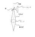
図1は、従来のペン型光マウスの動作概念を説明するための概略図である。 FIG. 1 is a schematic diagram for explaining an operation concept of a conventional pen-type optical mouse.
図1に示すように、発光部から入射された光が反射面から反射され、この反射された光が集光レンズおよび結像部を順次経過してイメージセンサに入射されることで、このイメージセンサにイメージが送られる。このとき、ペン型光マウスには、集光レンズの先端が押えられたときにクリックされるボタンが備わる。しかしながら、この集光レンズの押し動作により集光レンズまたは結像部の焦点距離が変化するため、イメージセンサに結ばれたイメージを最適の状態に維持できなくなる。したがって、従来のペン型光マウスは、結像状態をある程度認識可能な状態に維持するために、一般的に焦点距離を長く設定するが、この場合、光学系の設計において、構造及び性能上の多くの制約が伴う。特に、イメージセンサの位置や光学系が占める空間上の制約により、マウスの機能設定ボタンを所望の位置に配置できなくなる。これを補完するために、圧力センサを機能ボタンの代りに使用することもできるが、この場合、使用者が圧力センサの押し状態を感覚に依存して判断すべきであって、多くの不便さがある。また、使用上の便宜を考慮すると、ペン型光マウスは、使用者が手に持ちやすい形態及び大きさ(太さ)を有するべきである。しかしながら、従来のペン型光マウスのように、レンズのみを用いたペン型構造では、その大きさ(太さ)及び形態を使用者所望の水準に提供しにくい。 As shown in FIG. 1, the light incident from the light emitting portion is reflected from the reflecting surface, and the reflected light sequentially passes through the condenser lens and the image forming portion and enters the image sensor. An image is sent to the sensor. At this time, the pen-type optical mouse is provided with a button that is clicked when the tip of the condenser lens is pressed. However, since the focal length of the condensing lens or the imaging unit is changed by the pushing operation of the condensing lens, the image connected to the image sensor cannot be maintained in an optimum state. Therefore, a conventional pen-type light mouse generally sets a long focal length in order to maintain an imaging state in a state where it can be recognized to some extent. There are many restrictions. In particular, the function setting button of the mouse cannot be arranged at a desired position due to the position of the image sensor and the space restrictions occupied by the optical system. To compensate for this, a pressure sensor can be used instead of a function button, but in this case, the user should determine the pressing state of the pressure sensor depending on the sense, which is a lot of inconvenience. There is. In consideration of convenience in use, the pen-type optical mouse should have a form and size (thickness) that the user can easily hold. However, in a pen-type structure using only a lens like a conventional pen-type optical mouse, it is difficult to provide the size (thickness) and form to a user-desired level.
したがって、本発明が解決しようとする技術的課題は、新しい構造の光学系を採用して従来のペン型光マウスの使用上の欠点を改善できるペン型光マウスを提供することである。 Therefore, the technical problem to be solved by the present invention is to provide a pen-type light mouse that can improve the drawbacks of the conventional pen-type light mouse by adopting an optical system having a new structure.
本発明が解決しようとする他の技術的課題は、反射面との角度とは関係なしに自由に使用できるペン型光マウスを提供することである。 Another technical problem to be solved by the present invention is to provide a pen-type optical mouse that can be used freely regardless of the angle with the reflecting surface.
前記技術的課題を達成するために、本発明の一例によるペン型光マウスは、反射光を用いてマウスの動きを把握し、コンピュータモニター上の所望の位置にポインターまたはカーソルを表示するペン型マウスであって、ペン型のマウス本体と;前記マウス本体の一端に設置される透明な光学チップと;第1発光部と、前記第1発光部から発光された光を案内する第1光ファイバと、前記第1光ファイバの出力端に設置されるプリズムと、を含んで構成されており、前記マウス本体内に設置され、前記光学チップを通して前記マウス本体の外部に位置する反射面に光を照射する照明装置と;前記反射面から反射された光が自身を通過するように前記マウス本体内に設置される集光レンズと;前記集光レンズを通過した光を案内する光ファイバ束と;前記光ファイバ束から出る光を受けて結像する結像部と;前記結像部から出る光を受け、その光を電気的信号に変換するイメージセンサと;前記イメージセンサから出力される電気的信号に基づいてイメージセンサに入力された反射面のパターン情報を分析し、この分析されたパターン情報に基づいてマウスの移動方向及び移動距離を読み込み、この移動方向及び移動距離に対する情報をコンピュータ本体に送信するマイコンと;マウスを握った使用者の指により接触されるように前記マウス本体の側壁に設置される透明ボタンと、前記マウス本体内に設置され、前記透明ボタンを通して前記透明ボタンに接触される指に光を照射する第2発光部と、前記指から反射された後、前記透明ボタンを通過して入る反射光を受けて案内する第2光ファイバと、前記第2光ファイバを通して提供される光情報に基づいて指の動きを把握する位置感知センサと、を含んで構成され、スクロール機能を行う接触式ボタンセンサと;を備えることを特徴とする。In order to achieve the above technical problem, a pen-type optical mouse according to an example of the present invention uses a reflected light to grasp the movement of the mouse and displays a pointer or cursor at a desired position on a computer monitor. A pen-shaped mouse body; a transparent optical chip installed at one end of the mouse body; afirst light emitting unit; and afirst optical fiber for guiding light emitted fromthe first light emitting unit; And a prism installed at the output end ofthe first optical fiber, and is installed in the mouse body and irradiates light on a reflecting surface located outside the mouse body through the optical chip. An illuminating device; a condensing lens installed in the mouse body so that light reflected from the reflecting surface passes through; an optical fiber bundle for guiding the light that has passed through the condensing lens; An image forming unit that forms an image by receiving light emitted from the optical fiber bundle; an image sensor that receives the light emitted from the image forming unit and converts the light into an electrical signal; and an electrical signal output from the image sensor The pattern information of the reflecting surface input to the image sensor is analyzed based on the information, the moving direction and moving distance of the mouse are read based on the analyzed pattern information, and the information on the moving direction and moving distance is transmitted to the computer body. A microcomputerthat is placed on the side wall of the mouse body so as to be touched by a finger of a user who holds the mouse, and is placed in the mouse body and touches the transparent button through the transparent button A second light-emitting unit that irradiates light on the finger; and a second optical fiber that receives and guides the reflected light that passes through the transparent button after being reflected from the finger. A position sensing sensor that grasps the movement of a finger based on optical information provided through the second optical fiber, and a contact button sensor that performs a scroll function.
前記技術的課題を達成するために、本発明の他の例によるペン型光マウスは、反射光を用いてマウスの動きを把握し、コンピュータモニター上の所望の位置にポインターまたはカーソルを表示するペン型マウスであって、ペン型のマウス本体と;前記マウス本体の一端に設置される透明な光学チップと;第1発光部と、前記第1発光部から発光された光を案内する第1光ファイバと、前記第1光ファイバの出力端に設置されるプリズムと、を含んで構成されており、前記マウス本体内に設置され、前記マウス本体の外部に位置する反射面に光を照射する照明装置と;前記反射面から反射された光が前記光学チップを通して自身を通過するように前記マウス本体内に設置される集光レンズと;前記集光レンズを通過した光を案内する光ファイバ束と;前記光ファイバ束から出る光を受けて結像する結像部と;前記結像部から出る光を受け、その光を電気的信号に変換するイメージセンサと;前記イメージセンサから出力される電気的信号に基づいてイメージセンサに入力された反射面のパターン情報を分析し、この分析されたパターン情報に基づいてマウスの移動方向及び移動距離を読み込み、この移動方向及び移動距離に対する情報をコンピュータ本体に送信するマイコンと;マウスを握った使用者の指により接触されるように前記マウス本体の側壁に設置される透明ボタンと、前記マウス本体内に設置され、前記透明ボタンを通して前記透明ボタンに接触される指に光を照射する第2発光部と、前記指から反射された後、前記透明ボタンを通過して入る反射光を受けて案内する第2光ファイバと、前記第2光ファイバを通して提供される光情報に基づいて指の動きを把握する位置感知センサと、を含んで構成され、スクロール機能を行う接触式ボタンセンサと;を備えることを特徴とする。In order to achieve the above technical problem, a pen type optical mouse according to another example of the present invention uses a reflected light to grasp the movement of the mouse and displays a pointer or cursor at a desired position on a computer monitor. a type mouse, and a pen-type mouse body;first light guiding thefirst light emitting portion, the light emitted from thefirst light emitting portion; and a transparent optical chip installed at one end of the mouse body Illumination configured to include a fiber and a prism installed at an output end ofthe first optical fiber, and is installed in the mouse body and irradiates light on a reflection surface located outside the mouse body A condensing lens installed in the mouse body so that the light reflected from the reflecting surface passes through the optical chip; and an optical fiber bundle for guiding the light that has passed through the condensing lens An image forming unit that forms an image by receiving light emitted from the optical fiber bundle; an image sensor that receives the light emitted from the image forming unit and converts the light into an electrical signal; and an electric power output from the image sensor The pattern information of the reflecting surface input to the image sensor is analyzed based on the target signal, the moving direction and moving distance of the mouse are read based on the analyzed pattern information, and the information on the moving direction and moving distance is stored in the computer body. A microcomputer to transmit to; a transparent button installed on the side wall of the mouse body so as to be touched by a finger of a user who holds the mouse; and the transparent button installed in the mouse body and contacting the transparent button through the transparent button A second light emitting unit for irradiating the finger with light, and a second light beam for receiving and guiding the reflected light that passes through the transparent button after being reflected from the finger. And a position sensing sensor that grasps the movement of a finger based on optical information provided through the second optical fiber, and a contact-type button sensor that performs a scroll function. To do.
前記技術的課題を達成するために、本発明のさらに他の例によるペン型光マウスは、反射光を用いてマウスの動きを把握し、コンピュータモニター上の所望の位置にポインターまたはカーソルを表示するペン型マウスであって、ペン型のマウス本体と;前記マウス本体の一端に回転自在に設置され、表面にパターンを有するボールと;第1発光部と、前記第1発光部から発光された光を案内する第1光ファイバと、前記第1光ファイバの出力端に設置されるプリズムと、を含んで構成されており、前記マウス本体内に設置され、前記ボールに光を照射する照明装置と;前記ボールから反射された光が自身を通過するように前記マウス本体内に設置される集光レンズと;前記集光レンズを通過した光を案内する光ファイバ束と;前記光ファイバ束から出る光を受けて結像する結像部と;前記結像部から出る光を受け、その光を電気的信号に変換するイメージセンサと;前記イメージセンサから出力される電気的信号に基づいてイメージセンサに入力されたボール表面のパターン情報を分析し、この分析されたパターン情報に基づいてマウスの移動方向及び移動距離を読み込み、この移動方向及び移動距離に対する情報をコンピュータ本体に送信するマイコンと;マウスを握った使用者の指により接触されるように前記マウス本体の側壁に設置される透明ボタンと、前記マウス本体内に設置され、前記透明ボタンを通して前記透明ボタンに接触される指に光を照射する第2発光部と、前記指から反射された後、前記透明ボタンを通過して入る反射光を受けて案内する第2光ファイバと、前記第2光ファイバを通して提供される光情報に基づいて指の動きを把握する位置感知センサと、を含んで構成され、スクロール機能を行う接触式ボタンセンサと;を備えることを特徴とする。In order to achieve the above technical problem, a pen-type optical mouse according to still another example of the present invention grasps the movement of the mouse using reflected light and displays a pointer or cursor at a desired position on a computer monitor. A pen-type mouse, a pen-type mouse main body; a ball rotatably mounted on one end of the mouse main body and having a pattern on the surface; afirst light emitting unit, and light emitted fromthe first light emitting unit A lighting device for irradiating the ball with light,the first optical fiber for guidingthe light, and a prism installed at the output end ofthe first optical fiber. A condenser lens installed in the mouse body so that the light reflected from the ball passes through the optical fiber bundle; an optical fiber bundle for guiding the light that has passed through the condenser lens; An image forming unit that forms an image by receiving light emitted from the image forming unit; an image sensor that receives the light emitted from the image forming unit and converts the light into an electrical signal; and an image based on the electrical signal output from the image sensor. Analyzing the pattern information of the ball surface input to the sensor, reading the movement direction and movement distance of the mouse based on the analyzed pattern information, and transmitting information on the movement direction and movement distance to the computer main body; A transparent button installed on the side wall of the mouse main body so as to be touched by a finger of a user who holds the mouse, and a light which is installed in the mouse main body and touches the transparent button through the transparent button. A second light emitting unit for irradiating; a second optical fiber that receives and guides the reflected light that passes through the transparent button after being reflected from the finger; and the second optical fiber. A position sensing sensor that grasps the movement of a finger based on optical information provided through a fiber, and a contact button sensor that performs a scroll function.
前述した各例で、前記第1発光部は、LEDからなることを特徴とする。In each of the above-described examples,the first light emitting unit includes an LED.
前述した各例で、スクロール機能を行うホイールボタンセンサをさらに含み、前記ホイールボタンセンサは、軸を中心に回転するようにマウス本体の側壁に形成された開口部に嵌められるとともに、マウス本体の外側方向に前記開口部から部分的に突出され、その厚さ全体にかけて軸方向に延長されて円周方向に配置される複数個の貫通孔を有するホイールと;前記マウス本体内に設置されて前記ホイールに光を照射する第3発光部と;前記第3発光部から前記ホイールの前記各貫通孔をそれぞれ通過した光ビームを受け、前記ホイールの回転方向及び回転角度を把握する光センサと;を含んで構成されることを特徴とする。In each of the above-described examples, a wheel button sensor that performs a scroll function is further included, and the wheel button sensor is fitted into an opening formed in the side wall of the mouse body so as to rotate about an axis, and the outside of the mouse body. A wheel having a plurality of through-holes partially protruding from the opening in the direction and extending in the axial direction over the entire thickness thereof and disposed in the circumferential direction; Athird light emitting unit that irradiates light to the light; and a light sensor that receives a light beam that has passed through each of the through holes of the wheel fromthe third light emitting unit and grasps a rotation direction and a rotation angle of the wheel; It is characterized by comprising.
前述した各例で、前記光学チップを押したとき、この押し状態を感知してクリックされるように設置される第1クリックボタンと;指の押し動作によりクリックされるように、前記マウス本体の外面に設置される第2クリックボタンと;をさらに備えることを特徴とする。このとき、スクロール機能を行うホイールボタンセンサをさらに含み、前記ホイールボタンセンサは、軸を中心に回転するようにマウス本体の側壁に形成された開口部に嵌められるとともに、マウス本体の外側方向に前記開口部から部分的に突出され、その厚さ全体にかけて軸方向に延長されて円周方向に配置される複数個の貫通孔を有し、押されたとき、スプリングの弾性力に反してマウス本体の内側方向に引っ込み、スプリングの弾性力によりマウス本体の外側方向に突出して元の状態に復元されるホイールと;前記本体内に設置されて前記ホイールに光を照射する第3発光部と;前記第3発光部から前記ホイールの前記各貫通孔を通過した光ビームを受け、前記ホイールの回転方向及び回転角度を把握する光センサと;を含んで構成されており、前記第1クリックボタンは、前記ホイールが押されると、クリックされるように設置されることを特徴とする。または、前記透明ボタンは、押されたとき、スプリングの弾性力に反してマウス本体の内側方向に引っ込み、スプリングの弾性力によりマウス本体の外側方向に突出して元の状態に復元されるとともに、マウスを握った使用者の指により接触されるように前記マウス本体の外側壁に設置され、前記第1クリックボタンは、前記透明ボタンが押されると、クリックされるように設置されることを特徴とする。In each of the above-described examples, when the optical chip is pressed, a first click button is set so as to be clicked by detecting the pressed state; A second click button installed on the outer surface; and a second click button. At this time, it further includes a wheel button sensor that performs a scroll function, and the wheel button sensor is fitted into an opening formed in a side wall of the mouse body so as to rotate about an axis, and the wheel button sensor extends in an outward direction of the mouse body. The mouse body has a plurality of through-holes partially protruding from the opening, extending in the axial direction over the entire thickness thereof and arranged in the circumferential direction, and against the elastic force of the spring when pressed. A wheel that is retracted inwardly and protrudes outwardly of the mouse body by the elastic force of the spring; and is restored to its original state; athird light emitting unit that is installed in the body and irradiates light on the wheel; An optical sensor that receives a light beam that has passed through each of the through holes of the wheel from athird light emitting unit and grasps the rotation direction and the rotation angle of the wheel. The first click button is installed to be clicked when the wheel is pressed. Alternatively, when thetransparent button is pressed, it retracts inward of the mouse body against the elastic force of the spring, and protrudes outward of the mouse body due to the elastic force of the spring and is restored to the original state. placedoutside the side wall of the mouse body as contact by a finger of the user gripping the said first click button, when the transparent button is pressed, and wherein installed it is possible to be clicked To do.
前途した本発明の各例および利点は図を参照することでより明確な理解を得ることができるだろう。
以下、本発明の実施の形態を図面に基づいて説明する。
[実施形態1]
図2A乃至図2Fは、本発明の第1実施形態によるペン型光マウスを説明するための図である。Hereinafter, embodiments of the present invention will be described with reference to the drawings.
[Embodiment 1]
2A to 2F are views for explaining a pen-type optical mouse according to the first embodiment of the present invention.
図2A乃至図2Cに示すように、本発明の第1実施形態によるペン型光マウスは、マウス本体110を備えており、このマウス本体110内には、光学チップ120と、第1および第2クリックボタン131,132と、ホイールボタンセンサ140または接触式ボタンセンサと、照明装置150と、集光レンズ161と、光ファイバ束162と、結像部163と、イメージセンサ170と、マイコン(図示せず)と、が備わる。 As shown in FIGS. 2A to 2C, the pen-type optical mouse according to the first embodiment of the present invention includes a mouse
マウス本体110は、私たち人間に最も親しい筆記道具であるペン形態を有する。本発明によりマウスをペン形態にすると、長時間使用しても疲労感を感じることなく、その携帯が簡便になり、狭い空間でも使用が容易になるとともに、精密な作業や筆記体の表現などに一層優れた機能を有するようになる。 The
光学チップ120は、透明体からなり、光学チップ120を反射面に当てて押したとき、スプリングの弾性力に反してマウス本体110の内側方向に移動し、押し状態が解除されたときは、スプリングの弾性力によりマウス本体110の外側方向に再び移動し、元の状態に復元される。また、光学チップ120は、左右に揺れないように、ホルダー(図示せず)により固定される。 The
通常のマウスの左側クリックボタンに該当する第1クリックボタン131は、光学チップ120がマウス本体110の内側方向に移動するときにクリックされるように、マウス本体110に設置される。通常のマウスの右側クリックボタンに該当する第2クリックボタン132は、指の押し動作によりクリックされるように、マウス本体110の外面に設置される。一般に、スプリングは、第1クリックボタン131のクリック作用に用いられるが、スプリングの代りに圧力センサを使用することもできる。この場合、圧力センサは、光学チップ120の押し状態を感知して第1クリックボタン131がクリックされるよう作動する。 A
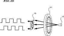
図2Bに結び付けて図2Dを参照すると、ホイールボタンセンサ140は、ホイール141と、発光部142と、光センサ143と、を含んでスクロール機能を持つ。 Referring to FIG. 2D in connection with FIG. 2B, the
ホイール141には、このホイール141の厚さ全体にかけて軸方向に延長されるとともに、円周方向に配置される複数個の貫通孔が設けられている。また、このホイール141は、軸を中心に回転するようにマウス本体110の側壁に形成された開口部に嵌められるとともに、マウス本体110の外側方向にその開口部から部分的に突出されている。発光部142は、マウス本体110内に設置されてホイール141に光を照射する。光センサ143は、ホイール141の各貫通孔を通過した光ビームをそれぞれ受け、この光ビームを位相差の異なる電気的信号に変換する。前記電気的信号に基づいて、光センサ143は、ホイール141の回転方向及び回転角度を把握する。このとき、ホイール141は、回転運動もするが、押されたとき、スプリングの弾性力に反してマウス本体110の内側方向に引っ込み、押し状態が解除されると、スプリングの弾性力によりマウス本体110の外側方向に突出して元の状態に復元される。ホイール141が押されてマウス本体110の内側方向に移動するときは、第1クリックボタン131がクリックされるようにして、通常のマウスの左側クリックボタンに該当する機能が行われる。 The
一方、ホイールボタンセンサ140に含まれる、ホイール141には小型化する限界があり、ペン型光マウスを小型化するのに大きな障害となっている、したがって、ホイールボタンセンサ140のスクロール機能と同一の機能を行う接触式ボタンセンサを採用することができる。 On the other hand, the
図2Aに結び付けて図2Eを参照すると、接触式ボタンセンサ180は、透明ボタン181と、発光部182と、光ファイバ(図示せず)と、位置感知センサ183と、を含んで構成される。 Referring to FIG. 2E in connection with FIG. 2A, the contact button sensor 180 includes a
透明ボタン181は、マウスを握った使用者の指により接触されるように、マウス本体110の側壁に設置される。発光部182は、マウス本体110内に設置され、透明ボタン181を通して、この透明ボタン181に接触される使用者の指に光を照射する。光ファイバは、指から反射された後、透明ボタン181を通過して入る光を受け、この反射した光を位置感知センサ183に案内する。位置感知センサ183は、光ファイバを通して受けた光情報に基づいて指の動きを把握する。このとき、透明ボタン181は、押されるとき、スプリングの弾性力に反してマウス本体110の内側方向に引っ込み、押し状態が解除されると、スプリングの弾性力によりマウス本体110の外側方向に突出されて元の状態に復元される。透明ボタン181は、押されてマウス本体110の内側方向に移動するとき、第1クリックボタン131がクリックされるようにして、通常のマウスの左側クリックボタンに該当する機能が行われる。 The
指には指紋があるため、指から反射された光は、それぞれ特定のパルス波形を有するようになる。すなわち、透明ボタン181に接触する指の移動方向によって、この特定のパルス波形が特定の位相を有するので、接触式ボタンセンサ180は、このパルス波形の位相を検出して指のスクロール方向を判断することができる。 Since the finger has a fingerprint, each light reflected from the finger has a specific pulse waveform. That is, since the specific pulse waveform has a specific phase depending on the moving direction of the finger touching the
第1クリックボタン131、第2クリックボタン132、ホイール141及び透明ボタン181は、通常のマウスと同じ方式で動作される。すなわち、本発明のペン型光マウスは、光学チップ120を反射面に当てて押すか、指によりホイール141または透明ボタン181を押すことで、表示窓の使用者所望のアイコンなどを選択し、第2クリックボタン132を押すことで、表示窓のポップアップメニュー窓が表示されるようにして、使用者は、ポップアップメニューに表示された各機能を選択することができる。もちろん、ホイール141または透明ボタン181を用いて、表示窓に表示された画面を上下にスクロールすることもできる。 The
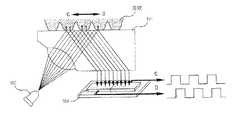
また、図2A乃至図2Cに示すように、照明装置150は、光学チップ120を通して、マウス本体110の外部に位置する反射面に光を照射する機能をする。この機能を行うために、照明装置150は、発光部151と、この発光部151から発光された光を案内する光ファイバ152と、この光ファイバ152の出力端に設置されるプリズム153と、から構成される。発光部151には、LED(Light Emitting Diode)またはEL(Electro Luminescent)素子などが使用される。 2A to 2C, the
前記構造を有する光マウスは、照明装置150から照射された後、凹凸パターンを有する反射面から不規則に反射される光をイメージセンサ170により読み込んで反射面の凹凸パターンを感知し、移動によって感知された凹凸パターンの変位を測定して光マウスの移動方向および移動距離を測定するようになる。 The optical mouse having the above-described structure reads the light irregularly reflected from the reflecting surface having the concavo-convex pattern after being irradiated from the
図2Fは、一般的なコピー用紙や机の表面を反射面にしてペン型光マウスを使用する場合を示した概略図であって、図2Fの(1)は、反射面に入射される光の入射角が大きい場合を、図2Fの(2)は、反射面に入射される光の入射角が小さい場合をそれぞれ示している。 FIG. 2F is a schematic view showing a case where a pen-type optical mouse is used with a general copy paper or desk surface as a reflection surface. FIG. 2F shows (1) light incident on the reflection surface. (2) in FIG. 2F shows the case where the incident angle of the light incident on the reflecting surface is small.
図2Fに示すように、入射角が小さい場合に入射光を受ける面積は、入射角が大きい場合に入射光を受ける面積よりも小さいため、入射光を反射する凹凸パターンの個数が減少する。よって、イメージセンサは、入射角が小さい場合、反射面の凹凸パターンを正確に区別することができる。 As shown in FIG. 2F, since the area that receives incident light when the incident angle is small is smaller than the area that receives incident light when the incident angle is large, the number of concavo-convex patterns that reflect incident light decreases. Therefore, the image sensor can accurately distinguish the concave / convex pattern on the reflecting surface when the incident angle is small.
したがって、本発明の実施形態によるペン型光マウスにおいては、ペン型光マウスが反射面に対して40゜〜70゜の角度を形成する場合、照明装置150から照射された光が14゜〜21゜の入射角で反射面に入射されるように照明装置150が設置される。 Therefore, in the pen-type optical mouse according to the embodiment of the present invention, when the pen-type optical mouse forms an angle of 40 ° to 70 ° with respect to the reflecting surface, the light emitted from the
また、図2A乃至図2Cに示すように、反射面に照射された光は、反射面から反射されてマウス本体110の内側に入り、集光レンズ161、光ファイバ束162及び結像部163を順次経過してイメージセンサ170に到達する。 Further, as shown in FIGS. 2A to 2C, the light irradiated on the reflecting surface is reflected from the reflecting surface and enters the inside of the mouse
集光レンズ161は、マウス本体110の内側に入った光が光ファイバ束162によく集光されるようにする。光ファイバ束162は、光ファイバ束162自体のイメージガイディング(image guiding)特性によって、集光レンズ161を通過した光を歪曲なしに結像部163に伝達する。結像部163は、結像レンズからなり、光ファイバ束162から出る光がイメージセンサ170に正確な像として結ばれるようにする。このとき、光ファイバ束162は、光を安定的に案内するために、固定台などを用いて両端が集光レンズ161及び結像部163にそれぞれ固定されるように設置される。 The condensing
前述したように、従来のペン型光マウスは、光学チップを押して第1クリックボタンがクリックされるとき、反射面からイメージセンサまでの距離が変わるようになり、ポインターおよびカーソルの座標値測定に問題が発生する。しかしながら、本発明の場合、光学チップ120を押したとき、反射面からイメージセンサ170までの直線距離は変わるが、光ファイバ束162は、柔軟性があって曲がるだけで、それ自体の長さが変わることはないので、反射面からイメージセンサ170までの距離変化に影響を受けない。したがって、ポインターおよびカーソルの座標値を正確に測定することができる。 As described above, in the conventional pen-type optical mouse, when the first click button is clicked by pressing the optical chip, the distance from the reflective surface to the image sensor changes, which causes a problem in measuring the coordinate values of the pointer and the cursor. Will occur. However, in the case of the present invention, when the
イメージセンサ170は、結像部163から出た光を受け、これを電気的信号に変換する。イメージセンサ170には、CMOSセンサやCCD(charge coupled device)などを使用することができ、CMOSセンサを使用する場合、マイコン回路と共に一つのチップにパッケージングできるという長所がある。マイコン(図示せず)は、イメージセンサ170から出力される電気的信号に基づいてイメージセンサ170に入力された反射面の凹凸パターン情報を分析し、マウスの移動方向及び移動距離を読み込み、これをコンピュータ本体(図示せず)に送信する。 The
一方、結像部163およびイメージセンサ170は、光マウスの大きさ及び太さを考慮して、それらの光軸が一直線をなすように設置してもよく、結像部163は、鏡および結像レンズにより構成することで、入力された光を屈折して出力し、イメージセンサ170は、屈折した光が入力されるように設置してもよい。
[実施形態2]
図3は、本発明の第2実施形態によるペン型光マウスを説明するための概略図である。On the other hand, the
[Embodiment 2]
FIG. 3 is a schematic view for explaining a pen-type optical mouse according to a second embodiment of the present invention.
本発明の第2実施形態によるペン型光マウスは、マウス本体を備えており、このマウス本体内には、光学チップと、各クリックボタンと、ホイールボタンセンサまたは接触式ボタンセンサと、照明装置と、集光レンズと、光ファイバ束と、結像部と、イメージセンサと、マイコンと、が備わる。本実施形態は、第1実施形態と比較すると、照明装置および集光レンズの設置位置が異なるだけで、他の構成要素の機能などは同一なので、反復される説明は省略する。 The pen-type optical mouse according to the second embodiment of the present invention includes a mouse body, and the mouse body includes an optical chip, each click button, a wheel button sensor or a contact button sensor, and an illumination device. , A condenser lens, an optical fiber bundle, an imaging unit, an image sensor, and a microcomputer. Compared with the first embodiment, the present embodiment is different only in the installation positions of the illumination device and the condenser lens, and the functions of other components are the same, and thus repeated description is omitted.
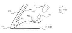
図2Aに結び付けて図3を参照すると、本実施形態によるペン型光マウスの照明装置150は、光学チップ120を通過せずに直接反射面に光を照射し、集光レンズ161は、反射面から反射された光が光学チップ120から出た後、自身を通過するように光学チップ120の内側に設置される。この実施形態において、ペン型光マウスが反射面に対して40゜〜70゜の角度を形成する場合、発光部151から照射された光が14゜〜21゜の入射角で反射面に入射されるように照明装置150が設置され、光ファイバ束162の両端は、固定台などを用いて集光レンズ161及び結像部163にそれぞれ固定されるように設置される。 Referring to FIG. 3 in connection with FIG. 2A, the pen-type optical
この場合、映像は、反射面に直接接触される光学チップ120の先端からイメージセンサ170に入力されるので、光学チップ120の先端の左右揺れがない限り、ペン型光マウスと反射面との角度がある程度変化しても、ポインターおよびカーソルの位置や焦点距離の変化はないので、ペン型光マウスの使用における精密度を一層高めることができる。
[実施形態3]
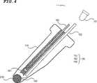
図4は、本発明の第3実施形態によるペン型光マウスを説明するための概略図である。In this case, the image is input to the
[Embodiment 3]
FIG. 4 is a schematic view for explaining a pen-type optical mouse according to a third embodiment of the present invention.
本発明の第3実施形態によるペン型光マウスは、マウス本体を備えており、このマウス本体内には、ボールと、各クリックボタンと、ホイールボタンセンサまたは接触式ボタンセンサと、照明装置と、集光レンズと、光ファイバ束と、結像部と、イメージセンサと、マイコンと、が備わる。本実施形態は、第1実施形態と比較すると、光学チップの代わりにボールが備わる点と、照明装置からの光照射領域および集光レンズの設置位置が異なるだけで、他の構成要素の機能などは同一であるので、反復される説明は省略する。 The pen-type optical mouse according to the third embodiment of the present invention includes a mouse body, and in the mouse body, a ball, each click button, a wheel button sensor or a contact button sensor, an illumination device, A condenser lens, an optical fiber bundle, an imaging unit, an image sensor, and a microcomputer are provided. Compared with the first embodiment, the present embodiment is different from the first embodiment in that a ball is provided instead of the optical chip, and only the light irradiation area from the illumination device and the installation position of the condenser lens are different. Are the same, the repeated description is omitted.
図2Aに結び付けて図4を参照すると、ボール210は、表面にパターンが形成されており、本体110の一端に回転自在に設置される。すなわち、ボール210は、実施形態1による光マウスにおける光学チップ120の設置位置に回転自在に設置される。 Referring to FIG. 4 in connection with FIG. 2A, the
照明装置150は、ボール210に光を照射するように設置される。実施形態1と同様に、照明装置150は、発光部151と、この発光部151から発光された光を案内する光ファイバ152と、この光ファイバ152の出力端に設置されるプリズム153と、を含んで構成される。 The
集光レンズ161は、ボール210の表面から反射された光が自身を通過するように設置され、光ファイバ束162の両端は、固定台などを用いて集光レンズ161及び結像部163にそれぞれ固定されるように設置される。 The condensing
この場合、特定のパターンを有するボール210をマウス本体110の端部に設置することで、ペン型光マウスを底面に接触して移動すると、ボール210が回転するようになり、イメージセンサ170は、集光レンズ161、光ファイバ束162および結像部163を通してボール210の表面に形成されたパターンを認識し、この認識されたボールパターンに基づいてマウスの移動方向を知ることができる。この場合、マウスの移動方向は、ボール210の回転により知ることができるので、反射面との角度とは関係なしに、自由に光マウスを使用できるという長所がある。 In this case, by placing the
本発明によると、光ファイバ束を通して光が伝播されるため、反射面からイメージセンサまでの距離及び光伝送経路に影響を受けることなく、光学系を用いてペン型光マウスを改善し、光学系の構造とは関係なしに映像伝送特性を実現することで、良好な映像をイメージセンサに伝達することができる。 According to the present invention, since light propagates through the optical fiber bundle, the pen-type optical mouse is improved using the optical system without being affected by the distance from the reflecting surface to the image sensor and the optical transmission path, and the optical system. By realizing the video transmission characteristics regardless of the structure, a good video can be transmitted to the image sensor.
また、反射面に直接接触される光学チップの先端からイメージセンサに映像を入力することで、反射面に対して形成されたペン型光マウスの角度がある程度変化しても、マウスポインターやカーソルの位置および焦点距離に変化がないので、ペン型光マウスの使用における精密度を一層高めることができる。 Also, by inputting an image to the image sensor from the tip of the optical chip that is in direct contact with the reflective surface, even if the angle of the pen-shaped optical mouse formed on the reflective surface changes to some extent, the mouse pointer or cursor Since there is no change in position and focal length, the precision in using a pen-type light mouse can be further increased.
また、特定のパターンを有するボールを本体の端部に設置し、そのボールから反射される光に基づいて光マウスの移動方向を把握することで、反射面に対して形成された光マウスの角度とは関係なしに自由に光マウスを使用することができる。 In addition, the angle of the optical mouse formed with respect to the reflective surface is determined by installing a ball having a specific pattern at the end of the main body and grasping the moving direction of the optical mouse based on the light reflected from the ball. You can use the light mouse freely regardless of the.
Claims (11)
Translated fromJapaneseペン型のマウス本体と;
前記マウス本体の一端に設置される透明な光学チップと;
第1発光部と、前記第1発光部から発光された光を案内する第1光ファイバと、前記第1光ファイバの出力端に設置されるプリズムと、を含んで構成されており、前記マウス本体内に設置され、前記光学チップを通して前記マウス本体の外部に位置する反射面に光を照射する照明装置と;
前記反射面から反射された光が自身を通過するように前記マウス本体内に設置される集光レンズと;
前記集光レンズを通過した光を案内する光ファイバ束と;
前記光ファイバ束から出る光を受けて結像する結像部と;
前記結像部から出る光を受け、その光を電気的信号に変換するイメージセンサと;
前記イメージセンサから出力される電気的信号に基づいてイメージセンサに入力された反射面のパターン情報を分析し、この分析されたパターン情報に基づいてマウスの移動方向及び移動距離を読み込み、この移動方向及び移動距離に対する情報をコンピュータ本体に送信するマイコンと;
マウスを握った使用者の指により接触されるように前記マウス本体の側壁に設置される透明ボタンと、前記マウス本体内に設置され、前記透明ボタンを通して前記透明ボタンに接触される指に光を照射する第2発光部と、前記指から反射された後、前記透明ボタンを通過して入る反射光を受けて案内する第2光ファイバと、前記第2光ファイバを通して提供される光情報に基づいて指の動きを把握する位置感知センサと、を含んで構成され、スクロール機能を行う接触式ボタンセンサと;を備えることを特徴とするペン型光マウス。A pen-type light mouse that uses reflected light to grasp mouse movement and display a pointer or cursor at a desired position on a computer monitor;
A pen-shaped mouse body;
A transparent optical chip installed at one end of the mouse body;
The mouse comprising: afirst light emitting unit; afirst optical fiber that guides light emitted fromthe first light emitting unit; and a prism installed at an output end ofthe first optical fiber. An illuminating device that is installed inside the body and irradiates light on a reflecting surface located outside the mouse body through the optical chip;
A condensing lens installed in the mouse body so that light reflected from the reflecting surface passes through itself;
An optical fiber bundle for guiding light that has passed through the condenser lens;
An image forming unit that forms an image by receiving light emitted from the optical fiber bundle;
An image sensor that receives light emitted from the imaging unit and converts the light into an electrical signal;
Based on the electrical signal output from the image sensor, the pattern information of the reflecting surface input to the image sensor is analyzed, and the moving direction and moving distance of the mouse are read based on the analyzed pattern information.And a microcomputer for transmitting information on the moving distance to the computer body;
A transparent button installed on the side wall of the mouse main body so as to be touched by a finger of a user who holds the mouse, and a light which is installed in the mouse main body and touches the transparent button through the transparent button. Based on the second light emitting unit to be irradiated, the second optical fiber that receives and guides the reflected light that passes through the transparent button after being reflected from the finger, and optical information provided through the second optical fiber A pen-type optical mouse comprising: a position-sensitive sensor that grasps the movement of a finger, and a contact-type button sensor that performs a scroll function.
ペン型のマウス本体と;
前記マウス本体の一端に設置される透明な光学チップと;
第1発光部と、前記第1発光部から発光された光を案内する第1光ファイバと、前記第1光ファイバの出力端に設置されるプリズムと、を含んで構成されており、前記マウス本体内に設置され、前記マウス本体の外部に位置する反射面に光を照射する照明装置と;
前記反射面から反射された光が前記光学チップを通して自身を通過するように前記マウス本体内に設置される集光レンズと;
前記集光レンズを通過した光を案内する光ファイバ束と;
前記光ファイバ束から出る光を受けて結像する結像部と;
前記結像部から出る光を受け、その光を電気的信号に変換するイメージセンサと;
前記イメージセンサから出力される電気的信号に基づいてイメージセンサに入力された反射面のパターン情報を分析し、この分析されたパターン情報に基づいてマウスの移動方向及び移動距離を読み込み、この移動方向及び移動距離に対する情報をコンピュータ本体に送信するマイコンと;
マウスを握った使用者の指により接触されるように前記マウス本体の側壁に設置される透明ボタンと、前記マウス本体内に設置され、前記透明ボタンを通して前記透明ボタンに接触される指に光を照射する第2発光部と、前記指から反射された後、前記透明ボタンを通過して入る反射光を受けて案内する第2光ファイバと、前記第2光ファイバを通して提供される光情報に基づいて指の動きを把握する位置感知センサと、を含んで構成され、スクロール機能を行う接触式ボタンセンサと;を備えることを特徴とするペン型光マウス。A pen-type light mouse that uses reflected light to grasp mouse movement and display a pointer or cursor at a desired position on a computer monitor;
A pen-shaped mouse body;
A transparent optical chip installed at one end of the mouse body;
The mouse comprising: afirst light emitting unit; afirst optical fiber that guides light emitted fromthe first light emitting unit; and a prism installed at an output end ofthe first optical fiber. An illuminating device that is installed inside the body and irradiates light on a reflecting surface located outside the mouse body;
A condenser lens installed in the mouse body so that light reflected from the reflecting surface passes through the optical chip;
An optical fiber bundle for guiding light that has passed through the condenser lens;
An image forming unit that forms an image by receiving light emitted from the optical fiber bundle;
An image sensor that receives light emitted from the imaging unit and converts the light into an electrical signal;
Based on the electrical signal output from the image sensor, the pattern information of the reflecting surface input to the image sensor is analyzed, and the moving direction and moving distance of the mouse are read based on the analyzed pattern information.And a microcomputer for transmitting information on the moving distance to the computer body;
A transparent button installed on the side wall of the mouse main body so as to be touched by a finger of a user who holds the mouse, and a light which is installed in the mouse main body and touches the transparent button through the transparent button. Based on the second light emitting unit to be irradiated, the second optical fiber that receives and guides the reflected light that passes through the transparent button after being reflected from the finger, and optical information provided through the second optical fiber A pen-type optical mouse comprising: a position-sensitive sensor that grasps the movement of a finger, and a contact-type button sensor that performs a scroll function.
ペン型のマウス本体と;
前記マウス本体の一端に回転自在に設置され、表面にパターンを有するボールと;
第1発光部と、前記第1発光部から発光された光を案内する第1光ファイバと、前記第1光ファイバの出力端に設置されるプリズムと、を含んで構成されており、前記マウス本体内に設置され、前記ボールに光を照射する照明装置と;
前記ボールから反射された光が自身を通過するように前記マウス本体内に設置される集光レンズと;
前記集光レンズを通過した光を案内する光ファイバ束と;
前記光ファイバ束から出る光を受けて結像する結像部と;
前記結像部から出る光を受け、その光を電気的信号に変換するイメージセンサと;
前記イメージセンサから出力される電気的信号に基づいてイメージセンサに入力されたボール表面のパターン情報を分析し、この分析されたパターン情報に基づいてマウスの移動方向及び移動距離を読み込み、この移動方向及び移動距離に対する情報をコンピュータ本体に送信するマイコンと;
マウスを握った使用者の指により接触されるように前記マウス本体の側壁に設置される透明ボタンと、前記マウス本体内に設置され、前記透明ボタンを通して前記透明ボタンに接触される指に光を照射する第2発光部と、前記指から反射された後、前記透明ボタンを通過して入る反射光を受けて案内する第2光ファイバと、前記第2光ファイバを通して提供される光情報に基づいて指の動きを把握する位置感知センサと、を含んで構成され、スクロール機能を行う接触式ボタンセンサと;を備えることを特徴とするペン型光マウス。A pen-type light mouse that uses reflected light to grasp mouse movement and display a pointer or cursor at a desired position on a computer monitor;
A pen-shaped mouse body;
A ball rotatably mounted at one end of the mouse body and having a pattern on the surface;
The mouse comprising: afirst light emitting unit; afirst optical fiber that guides light emitted fromthe first light emitting unit; and a prism installed at an output end ofthe first optical fiber. A lighting device installed in the body and irradiating the ball with light;
A condenser lens installed in the mouse body such that light reflected from the ball passes through the ball;
An optical fiber bundle for guiding light that has passed through the condenser lens;
An image forming unit that forms an image by receiving light emitted from the optical fiber bundle;
An image sensor that receives light emitted from the imaging unit and converts the light into an electrical signal;
The ball surface pattern information input to the image sensor is analyzed based on the electrical signal output from the image sensor, and the movement direction and distance of the mouse are read based on the analyzed pattern information.And a microcomputer for transmitting information on the moving distance to the computer body;
A transparent button installed on the side wall of the mouse main body so as to be touched by a finger of a user who holds the mouse, and a light which is installed in the mouse main body and touches the transparent button through the transparent button. Based on the second light emitting unit to be irradiated, the second optical fiber that receives and guides the reflected light that passes through the transparent button after being reflected from the finger, and optical information provided through the second optical fiber A pen-type optical mouse comprising: a position-sensitive sensor that grasps the movement of a finger, and a contact-type button sensor that performs a scroll function.
前記イメージセンサは、前記結像部から屈折した光が入力されるように設置されることを特徴とする請求項1乃至3のいずれか一つに記載のペン型光マウス。The imaging unit is installed to refract input light,
The pen-type optical mouse according to any one of claims 1 to 3, wherein the image sensor is installed so that light refracted from the imaging unit is input.
指の押し動作によりクリックされるように、前記マウス本体の外面に設置される第2クリックボタンと;をさらに備えることを特徴とする請求項1乃至3のいずれか一つに記載のペン型光マウス。A first click button installed so that when the optical chip is pressed, the pressing state is detected and clicked;
4. The pen-type light according to claim 1, further comprising: a second click button installed on an outer surface of the mouse body so as to be clicked by a finger pressing operation. 5. mouse.
前記ホイールボタンセンサは、軸を中心に回転するようにマウス本体の側壁に形成された開口部に嵌められるとともに、マウス本体の外側方向に前記開口部から部分的に突出され、その厚さ全体にかけて軸方向に延長されて円周方向に配置される複数個の貫通孔を有するホイールと;
前記本体内に設置されて前記ホイールに光を照射する第3発光部と;
前記第3発光部から前記ホイールの前記各貫通孔をそれぞれ通過した光ビームを受け、前記ホイールの回転方向及び回転角度を把握する光センサと;を含んで構成されることを特徴とする請求項1乃至3のいずれか一つに記載のペン型光マウス。A wheel button sensor for performing a scroll function;
The wheel button sensor is fitted into an opening formed on the side wall of the mouse body so as to rotate about an axis, and partially protrudes from the opening toward the outside of the mouse body, and extends over the entire thickness. A wheel having a plurality of through-holes extending in the axial direction and arranged circumferentially;
Athird light emitting unit installed in the main body and irradiating the wheel with light;
An optical sensor that receives a light beam that has passed through each of the through holes of the wheel fromthe third light emitting unit and grasps a rotation direction and a rotation angle of the wheel. The pen-type light mouse according to any one of 1 to 3.
前記ホイールボタンセンサは、軸を中心に回転するようにマウス本体の側壁に形成された開口部に嵌められるとともに、マウス本体の外側方向に前記開口部から部分的に突出され、その厚さ全体にかけて軸方向に延長されて円周方向に配置される複数個の貫通孔を有し、押されたとき、スプリングの弾性力に反してマウス本体の内側方向に引っ込み、スプリングの弾性力によりマウス本体の外側方向に突出して元の状態に復元されるホイールと;
前記本体内に設置されて前記ホイールに光を照射する第3発光部と;
前記第3発光部から前記ホイールの前記各貫通孔を通過した光ビームを受け、前記ホイールの回転方向及び回転角度を把握する光センサと;を含んで構成されており、
前記第1クリックボタンは、前記ホイールが押されると、クリックされるように設置されることを特徴とする請求項7記載のペン型光マウス。A wheel button sensor for performing a scroll function;
The wheel button sensor is fitted into an opening formed on the side wall of the mouse body so as to rotate about an axis, and partially protrudes from the opening toward the outside of the mouse body, and extends over the entire thickness. It has a plurality of through-holes that extend in the axial direction and are arranged in the circumferential direction, and when pressed, it retracts inward of the mouse body against the elastic force of the spring, and the elastic force of the spring A wheel protruding outwards and restored to its original state;
Athird light emitting unit installed in the main body and irradiating the wheel with light;
An optical sensor that receives a light beam that has passed through each of the through holes of the wheel fromthe third light emitting unit and grasps a rotation direction and a rotation angle of the wheel; and
The pen-type optical mouse according to claim 7, wherein the first click button is installed to be clicked when the wheel is pressed.
Applications Claiming Priority (3)
| Application Number | Priority Date | Filing Date | Title |
|---|---|---|---|
| KR10-2002-0061638AKR100532929B1 (en) | 2002-10-10 | 2002-10-10 | Optical Pen Mouse |
| KR10-2003-0009747AKR100495688B1 (en) | 2003-02-17 | 2003-02-17 | Pen type optical mouse |
| PCT/KR2003/001674WO2004034244A1 (en) | 2002-10-10 | 2003-08-20 | Pen-shaped optical mouse |
Publications (2)
| Publication Number | Publication Date |
|---|---|
| JP2006503381A JP2006503381A (en) | 2006-01-26 |
| JP4100575B2true JP4100575B2 (en) | 2008-06-11 |
Family
ID=32095496
Family Applications (1)
| Application Number | Title | Priority Date | Filing Date |
|---|---|---|---|
| JP2005501030AExpired - Fee RelatedJP4100575B2 (en) | 2002-10-10 | 2003-08-20 | Pen-shaped light mouse |
Country Status (6)
| Country | Link |
|---|---|
| US (1) | US20060028456A1 (en) |
| EP (1) | EP1550028A1 (en) |
| JP (1) | JP4100575B2 (en) |
| CA (1) | CA2502235A1 (en) |
| TW (1) | TW200405984A (en) |
| WO (1) | WO2004034244A1 (en) |
Families Citing this family (66)
| Publication number | Priority date | Publication date | Assignee | Title |
|---|---|---|---|---|
| US6803906B1 (en)* | 2000-07-05 | 2004-10-12 | Smart Technologies, Inc. | Passive touch system and method of detecting user input |
| US6954197B2 (en)* | 2002-11-15 | 2005-10-11 | Smart Technologies Inc. | Size/scale and orientation determination of a pointer in a camera-based touch system |
| US8456447B2 (en) | 2003-02-14 | 2013-06-04 | Next Holdings Limited | Touch screen signal processing |
| US8508508B2 (en) | 2003-02-14 | 2013-08-13 | Next Holdings Limited | Touch screen signal processing with single-point calibration |
| US7629967B2 (en)* | 2003-02-14 | 2009-12-08 | Next Holdings Limited | Touch screen signal processing |
| US7532206B2 (en)* | 2003-03-11 | 2009-05-12 | Smart Technologies Ulc | System and method for differentiating between pointers used to contact touch surface |
| US7411575B2 (en)* | 2003-09-16 | 2008-08-12 | Smart Technologies Ulc | Gesture recognition method and touch system incorporating the same |
| US7274356B2 (en)* | 2003-10-09 | 2007-09-25 | Smart Technologies Inc. | Apparatus for determining the location of a pointer within a region of interest |
| US20050104871A1 (en)* | 2003-11-15 | 2005-05-19 | Qing Liu | Computer input device |
| US7355593B2 (en) | 2004-01-02 | 2008-04-08 | Smart Technologies, Inc. | Pointer tracking across multiple overlapping coordinate input sub-regions defining a generally contiguous input region |
| US7460110B2 (en)* | 2004-04-29 | 2008-12-02 | Smart Technologies Ulc | Dual mode touch system |
| US7492357B2 (en)* | 2004-05-05 | 2009-02-17 | Smart Technologies Ulc | Apparatus and method for detecting a pointer relative to a touch surface |
| US7538759B2 (en) | 2004-05-07 | 2009-05-26 | Next Holdings Limited | Touch panel display system with illumination and detection provided from a single edge |
| US8120596B2 (en)* | 2004-05-21 | 2012-02-21 | Smart Technologies Ulc | Tiled touch system |
| KR100792625B1 (en) | 2004-07-27 | 2008-01-09 | 인하대학교 산학협력단 | Portable terminal information input device using distributed optical mouse |
| US20060084039A1 (en)* | 2004-10-19 | 2006-04-20 | Massachusetts Institute Of Technology | Drawing tool for capturing and rendering colors, surface images and movement |
| TWI269995B (en)* | 2005-01-10 | 2007-01-01 | Aiptek Int Inc | An optical pen having a light path coaxial with its pen tip |
| TW200632729A (en)* | 2005-03-11 | 2006-09-16 | Aiptek Int Inc | Light guiding apparatus of optical pen |
| GB2428785A (en)* | 2005-07-27 | 2007-02-07 | Foxlink Image Tech Co Ltd | Pen like optical mouse |
| US8090092B2 (en)* | 2006-05-02 | 2012-01-03 | Skype Limited | Dialling phone numbers |
| EP1909162A1 (en)* | 2006-10-02 | 2008-04-09 | Koninklijke Philips Electronics N.V. | System for virtually drawing on a physical surface |
| US9442607B2 (en)* | 2006-12-04 | 2016-09-13 | Smart Technologies Inc. | Interactive input system and method |
| US7626705B2 (en) | 2007-03-30 | 2009-12-01 | Mitutoyo Corporation | Chromatic sensor lens configuration |
| US8115753B2 (en)* | 2007-04-11 | 2012-02-14 | Next Holdings Limited | Touch screen system with hover and click input methods |
| US8094137B2 (en)* | 2007-07-23 | 2012-01-10 | Smart Technologies Ulc | System and method of detecting contact on a display |
| WO2009029767A1 (en)* | 2007-08-30 | 2009-03-05 | Next Holdings, Inc. | Optical touchscreen with improved illumination |
| US8384693B2 (en) | 2007-08-30 | 2013-02-26 | Next Holdings Limited | Low profile touch panel systems |
| US8405636B2 (en)* | 2008-01-07 | 2013-03-26 | Next Holdings Limited | Optical position sensing system and optical position sensor assembly |
| US20090213093A1 (en)* | 2008-01-07 | 2009-08-27 | Next Holdings Limited | Optical position sensor using retroreflection |
| US20090207144A1 (en)* | 2008-01-07 | 2009-08-20 | Next Holdings Limited | Position Sensing System With Edge Positioning Enhancement |
| US20090277697A1 (en)* | 2008-05-09 | 2009-11-12 | Smart Technologies Ulc | Interactive Input System And Pen Tool Therefor |
| US8902193B2 (en)* | 2008-05-09 | 2014-12-02 | Smart Technologies Ulc | Interactive input system and bezel therefor |
| US20090278795A1 (en)* | 2008-05-09 | 2009-11-12 | Smart Technologies Ulc | Interactive Input System And Illumination Assembly Therefor |
| US20090278794A1 (en)* | 2008-05-09 | 2009-11-12 | Smart Technologies Ulc | Interactive Input System With Controlled Lighting |
| TW201003469A (en)* | 2008-07-01 | 2010-01-16 | Avermedia Information Inc | Cursor control device |
| US20110205189A1 (en)* | 2008-10-02 | 2011-08-25 | John David Newton | Stereo Optical Sensors for Resolving Multi-Touch in a Touch Detection System |
| AT508519A1 (en)* | 2008-10-30 | 2011-02-15 | Isiqiri Interface Tech Gmbh | WRITING DEVICE AND METHOD FOR OPERATING A WRITING DEVICE |
| US8339378B2 (en)* | 2008-11-05 | 2012-12-25 | Smart Technologies Ulc | Interactive input system with multi-angle reflector |
| JP4291405B1 (en)* | 2008-11-14 | 2009-07-08 | 健治 吉田 | Mouse with dot pattern reading function |
| FR2943812B1 (en)* | 2009-03-27 | 2011-09-02 | Optinnova | PRECISION OPTICAL POINTER FOR INTERACTIVE WHITEBOARD, INTERACTIVE WHITEBOARD SYSTEM |
| US20110148824A1 (en)* | 2009-07-24 | 2011-06-23 | Seiko Epson Corporation | Optical pen |
| WO2011047618A1 (en)* | 2009-10-20 | 2011-04-28 | Tuan Hsi-Ching | Mouse pen and photoelectric control switch thereof |
| TW201115404A (en)* | 2009-10-21 | 2011-05-01 | Kye Systems Corp | Wear-on type input device |
| US20110095989A1 (en)* | 2009-10-23 | 2011-04-28 | Smart Technologies Ulc | Interactive input system and bezel therefor |
| US20110199387A1 (en)* | 2009-11-24 | 2011-08-18 | John David Newton | Activating Features on an Imaging Device Based on Manipulations |
| WO2011066343A2 (en)* | 2009-11-24 | 2011-06-03 | Next Holdings Limited | Methods and apparatus for gesture recognition mode control |
| US20110205186A1 (en)* | 2009-12-04 | 2011-08-25 | John David Newton | Imaging Methods and Systems for Position Detection |
| TWI402722B (en)* | 2009-12-24 | 2013-07-21 | Benq Corp | Optical pen and operating method of the same |
| US8134691B2 (en) | 2010-03-18 | 2012-03-13 | Mitutoyo Corporation | Lens configuration for a thermally compensated chromatic confocal point sensor |
| US20110234542A1 (en)* | 2010-03-26 | 2011-09-29 | Paul Marson | Methods and Systems Utilizing Multiple Wavelengths for Position Detection |
| TWI407335B (en)* | 2010-03-31 | 2013-09-01 | Kye Systems Corp | Pen type optical input device |
| TW201220136A (en)* | 2010-11-04 | 2012-05-16 | Hon Hai Prec Ind Co Ltd | Optical pen |
| SK5917Y1 (en)* | 2010-11-22 | 2011-11-04 | Stefan Valicek | Optics for pencil optical input computer peripheral controller |
| US8587522B2 (en) | 2011-01-18 | 2013-11-19 | Aaron DeJule | Mouse for operating an electronic device |
| US8212997B1 (en) | 2011-02-23 | 2012-07-03 | Mitutoyo Corporation | Chromatic confocal point sensor optical pen with extended measuring range |
| CN104142737B (en)* | 2013-05-07 | 2020-11-06 | 崔伟 | Digital pen and spray pen simulation method |
| US11112888B2 (en)* | 2015-07-15 | 2021-09-07 | Hewlett-Packard Development Company, L.P. | Pressure sensitive stylus |
| CZ2016111A3 (en)* | 2016-02-25 | 2016-11-09 | O.Pen S.R.O. | Wireless positioning pen with pressure tip |
| JP2018032397A (en)* | 2016-08-17 | 2018-03-01 | 株式会社半導体エネルギー研究所 | Touch input pen, electronic device, and method for input to electronic device with touch input pen |
| US10444866B2 (en)* | 2016-11-14 | 2019-10-15 | Microsoft Technology Licensing, Llc | Force sensor for a stylus |
| US10901538B2 (en)* | 2018-12-27 | 2021-01-26 | Pixart Imaging Inc. | Pen mouse |
| US11507206B2 (en)* | 2019-05-13 | 2022-11-22 | Microsoft Technology Licensing, Llc | Force-sensing input device |
| EP3822746A1 (en)* | 2019-11-15 | 2021-05-19 | Microsoft Technology Licensing, LLC | Mouse input function for pen-shaped writing, reading or pointing devices |
| US12353649B2 (en)* | 2022-06-29 | 2025-07-08 | Apple Inc. | Input device with optical sensors |
| JP2024018187A (en)* | 2022-07-29 | 2024-02-08 | セイコーエプソン株式会社 | electronic pen |
| CN115153510B (en)* | 2022-08-08 | 2023-08-04 | 芙索特(上海)医疗科技有限公司 | Scoliosis measuring device and measuring method |
Family Cites Families (12)
| Publication number | Priority date | Publication date | Assignee | Title |
|---|---|---|---|---|
| US4922236A (en)* | 1988-04-25 | 1990-05-01 | Richard Heady | Fiber optical mouse |
| US5013128A (en)* | 1990-06-07 | 1991-05-07 | General Dynamics Corporation, Convair Division | Fiber optic light guide with improved end-to-end efficiency |
| JPH04195321A (en)* | 1990-11-27 | 1992-07-15 | Matsushita Electric Ind Co Ltd | Pen type computer input device |
| JPH08185258A (en)* | 1994-12-27 | 1996-07-16 | Michihide Kondo | Spherical measurement sensor for ball-point pen or mouse for computer operation, and ball-point pen for computer operation |
| US5963195A (en)* | 1996-12-19 | 1999-10-05 | International Business Machines Corporation | Hardware-selectable mouse movement |
| TR199901910T2 (en)* | 1997-02-12 | 1999-10-21 | Kanitech A/S | A device used to enter data into a computer |
| US6151015A (en)* | 1998-04-27 | 2000-11-21 | Agilent Technologies | Pen like computer pointing device |
| CN1227617C (en)* | 2000-11-06 | 2005-11-16 | 皇家菲利浦电子有限公司 | Method of measuring movement of input device |
| EP1342151A4 (en)* | 2000-12-15 | 2007-02-28 | Finger System Inc | Pen type optical mouse device and method of controlling the same |
| KR100349031B1 (en)* | 2000-12-15 | 2002-08-17 | 핑거시스템 주식회사 | A pen type light mouse device |
| KR100375512B1 (en)* | 2000-12-21 | 2003-03-10 | 삼성전기주식회사 | Optical mouse of pen type |
| KR20020024265A (en)* | 2002-02-18 | 2002-03-29 | 양태훈 | Pen type optical mouse |
- 2003
- 2003-08-20USUS10/529,368patent/US20060028456A1/ennot_activeAbandoned
- 2003-08-20CACA002502235Apatent/CA2502235A1/ennot_activeAbandoned
- 2003-08-20EPEP03807992Apatent/EP1550028A1/ennot_activeWithdrawn
- 2003-08-20JPJP2005501030Apatent/JP4100575B2/ennot_activeExpired - Fee Related
- 2003-08-20WOPCT/KR2003/001674patent/WO2004034244A1/enactiveApplication Filing
- 2003-10-06TWTW092127642Apatent/TW200405984A/enunknown
Also Published As
| Publication number | Publication date |
|---|---|
| EP1550028A1 (en) | 2005-07-06 |
| CA2502235A1 (en) | 2004-04-22 |
| JP2006503381A (en) | 2006-01-26 |
| US20060028456A1 (en) | 2006-02-09 |
| WO2004034244A1 (en) | 2004-04-22 |
| TW200405984A (en) | 2004-04-16 |
Similar Documents
| Publication | Publication Date | Title |
|---|---|---|
| JP4100575B2 (en) | Pen-shaped light mouse | |
| US6151015A (en) | Pen like computer pointing device | |
| US7239302B2 (en) | Pointing device and scanner, robot, mobile communication device and electronic dictionary using the same | |
| US7839394B2 (en) | Electronic pen device | |
| US7737959B2 (en) | Position detection system using laser speckle | |
| US6985138B2 (en) | Input writing device | |
| KR100438846B1 (en) | Pen-type mouse apparatus | |
| US20150338933A1 (en) | Multi-function stylus for motion capture and sensory based machine control | |
| JP2006195928A (en) | Optical pen having optical path coaxial with pen tip | |
| KR100532929B1 (en) | Optical Pen Mouse | |
| US20110090178A1 (en) | Detecting method for pen-like optical input device with multiple optical components and optical input device thereof | |
| KR20030062032A (en) | Digital pen device | |
| US8531436B2 (en) | Specific wavelength selecting method for optical input device and optical input device thereof | |
| KR100495688B1 (en) | Pen type optical mouse | |
| KR100551213B1 (en) | Optical pen mouse | |
| KR20020024265A (en) | Pen type optical mouse | |
| KR200385582Y1 (en) | Pen-type mouse having mode-selection button | |
| KR100547090B1 (en) | Pen-shaped optical mouse | |
| JP2023151395A (en) | Electronic device | |
| KR20050076075A (en) | Pen type optical mouse equipped with the reflector | |
| US20070075964A1 (en) | Mobile pointing device | |
| IL199734A (en) | Electronic pen device |
Legal Events
| Date | Code | Title | Description |
|---|---|---|---|
| A131 | Notification of reasons for refusal | Free format text:JAPANESE INTERMEDIATE CODE: A131 Effective date:20070717 | |
| A601 | Written request for extension of time | Free format text:JAPANESE INTERMEDIATE CODE: A601 Effective date:20071001 | |
| A602 | Written permission of extension of time | Free format text:JAPANESE INTERMEDIATE CODE: A602 Effective date:20071009 | |
| A601 | Written request for extension of time | Free format text:JAPANESE INTERMEDIATE CODE: A601 Effective date:20071116 | |
| A602 | Written permission of extension of time | Free format text:JAPANESE INTERMEDIATE CODE: A602 Effective date:20071126 | |
| A601 | Written request for extension of time | Free format text:JAPANESE INTERMEDIATE CODE: A601 Effective date:20071203 | |
| A602 | Written permission of extension of time | Free format text:JAPANESE INTERMEDIATE CODE: A602 Effective date:20071218 | |
| TRDD | Decision of grant or rejection written | ||
| A01 | Written decision to grant a patent or to grant a registration (utility model) | Free format text:JAPANESE INTERMEDIATE CODE: A01 Effective date:20080212 | |
| A61 | First payment of annual fees (during grant procedure) | Free format text:JAPANESE INTERMEDIATE CODE: A61 Effective date:20080313 | |
| FPAY | Renewal fee payment (event date is renewal date of database) | Free format text:PAYMENT UNTIL: 20110328 Year of fee payment:3 | |
| R150 | Certificate of patent or registration of utility model | Free format text:JAPANESE INTERMEDIATE CODE: R150 | |
| LAPS | Cancellation because of no payment of annual fees |