JP4097914B2 - Mobile terminal compatible router - Google Patents
Mobile terminal compatible routerDownload PDFInfo
- Publication number
- JP4097914B2 JP4097914B2JP2001175933AJP2001175933AJP4097914B2JP 4097914 B2JP4097914 B2JP 4097914B2JP 2001175933 AJP2001175933 AJP 2001175933AJP 2001175933 AJP2001175933 AJP 2001175933AJP 4097914 B2JP4097914 B2JP 4097914B2
- Authority
- JP
- Japan
- Prior art keywords
- packet
- interface
- terminal
- binding
- router
- Prior art date
- Legal status (The legal status is an assumption and is not a legal conclusion. Google has not performed a legal analysis and makes no representation as to the accuracy of the status listed.)
- Expired - Fee Related
Links
Images


Classifications
- H—ELECTRICITY
- H04—ELECTRIC COMMUNICATION TECHNIQUE
- H04W—WIRELESS COMMUNICATION NETWORKS
- H04W88/00—Devices specially adapted for wireless communication networks, e.g. terminals, base stations or access point devices
- H04W88/005—Data network PoA devices
- H—ELECTRICITY
- H04—ELECTRIC COMMUNICATION TECHNIQUE
- H04W—WIRELESS COMMUNICATION NETWORKS
- H04W80/00—Wireless network protocols or protocol adaptations to wireless operation
- H04W80/04—Network layer protocols, e.g. mobile IP [Internet Protocol]
Landscapes
- Engineering & Computer Science (AREA)
- Computer Networks & Wireless Communication (AREA)
- Signal Processing (AREA)
- Data Exchanges In Wide-Area Networks (AREA)
- Mobile Radio Communication Systems (AREA)
Description
Translated fromJapanese【0001】
【発明の属する技術分野】
本発明は移動端末対応ルータに関し、モバイルIPv4/v6が動作するネットワークに接続された移動端末対応ルータに関するものである。
IPネットワークにおいて、端末がネットワーク上の接続位置を変えても通信を行うことを可能にするプロトコルとして、米国の標準化団体IETF(Internet Engineering Task Force)においてモバイル(Mobile)IPv4が文献RFC2002で標準化されている。
【0002】
また、近年、IPネットワーク上に存在する端末数の急増により、IPアドレス枯渇の問題が深刻化している。この問題を解決するため、より多くのIPアドレスを使用することが可能なIPv6が文献RFC2460で標準化され、このIPアドレスを使用したネットワークへの移行が本格化している。
【0003】
このため、通常のIPv4ネットワークにおけるモバイルIPだけでなく、IPv6ネットワーク上での端末の移動をサポートするプロトコルとしてモバイルIPv6の標準化は重要であり、IETFのモバイルIPワーキンググループ(IETF Mobile IP Working Group)においてRFC化のための審議が行われ標準草案(Draft Standard:文献draft-ietf-mobileip-ipv6-13.txt参照)が作成されている。
【0004】
【従来の技術】
上記の標準草案に基づくモバイルIPv6におけるパケット転送を以下に説明する。なお、モバイルIPv4とモバイルIPv6についての標準化の内容は同様であるため、モバイルIPv4の説明は省略する。
【0005】
図26は、一般的なインターネットネットワークを示している。このネットワークにおいては、ルータ110とルータ120はリンク250で接続され、ルータ110とルータ130はリンク240で接続されている。各ルータ110〜130には、それぞれ、リンク210,220,及び230が接続されている。移動端末300は、リンク210に接続されている。移動又は固定端末(host)310はリンク230に接続されている。
【0006】
リンク210,220,230,240,及び250のIPアドレス(サブネットプレフィックス:subnet prefix)は、それぞれ、“10.x”,“20.x”,“30.x”,“40.x”,及び“50.x”である。端末300及び310のIPアドレスは、それぞれ、“10.10”及び“30.11”である。
【0007】
モバイルIPv6では、例えば、端末300が通常接続しているリンク210を端末300のホームリンク(home link)又はホームネットワーク(home network)と称し、端末300のIPアドレス“10.10”を端末300のホームアドレス(Home Address)と称する。
【0008】
このホームリンク210上に端末300の移動をサポートするホームエージェント(home agent)が存在する。同図においては、ホームリンク210上のルータ110の中にホームエージェント11が存在するが、ホームエージェント11は必ずしもルータに存在する必要はなく、例えば、ホームリンク210上のサーバがホームエージェントの役割を果たしてもよい。
【0009】
また、ホームリンク210以外のリンク220〜250を、移動端末300の外部リンク(foreign link)と称する。
(1)移動端末の位置登録
端末300は、ホームリンク210から外部リンクに移動した場合に、外部リンクにおいて有効な移動先でのアドレスであるケア・オブ・アドレス(Care-of Address、以下、CoAと略称することがある。)を取得又は生成し、ホームエージェントに対してバインディング・アップデート(Binding Update、以下、バインディング要求パケットと称することがある。)を送信し、ケア・オブ・アドレスの登録を行う。なお、バインディング・アップデートは、モバイルIPv4における登録要求(Registration Request)メッセージに相当する。
【0010】
バインディング・アップデートを受信したホームエージェントは、端末300のホームアドレス、ケア・オブ・アドレス、及び登録の有効時間等を記憶するバインディング・キャッシュ(Binding Cache)14を生成する。
以下に、このIPv6における移動端末の位置登録の動作手順をより具体的に説明する。
【0011】
▲1▼端末300(ホームアドレス=10.10)がホームリンク210から外部リンク220に移動する。
▲2▼端末300は、リンク220上のルータ120が送信するルータ広告メッセージの内容から接続しているリンクが変わったことを検出し、リンク220上で有効なケア・オブ・アドレス(ここでは“20.10”)を生成する。
【0012】
▲3▼端末300は、リンク210を管理するホームエージェント(ここではルータ110内)11にバインディング・アップデートを送信し、ケア・オブ・アドレスの登録を行う。
▲4▼ホームエージェント11は、端末300からのバインディング・アップデートを元に端末300についてのバインディング・キャッシュ14を生成する。
【0013】
なお、このバインディング・キャッシュ14には、登録有効時間が設定されており、有効時間経過後に消去される。
▲5▼さらに、ホームエージェント11は、応答としてバインディング・アクノリッジメント(Binding Acknowledgement、以後、バインディング応答パケットと称することがある。)を端末300に返信する。端末300は、バインディング・アクノリッジメントを受信し、登録を完了したことを認識する。
【0014】
なお、バインディング・アクノリッジメントは、モバイルIPv4における登録応答(Registration Reply)メッセージに相当する。
以後、端末300は、リンク220にて通信を行う間、ホームエージェント11におけるバインディング・キャッシュ14を保持するために▲3▼と同様にバインディング・アップデートを周期的にホームエージェントに送信する。
【0015】
ホームエージェント11は、バインディング・キャッシュ14とその有効時間の更新を行う。
(2)移動端末宛パケットの転送
図27は、モバイルIPv6におけるパケット転送例を示している。この例では、ルータ110が、移動端末300のバインディング・キャッシュ14が上記の位置登録によって有効であるとき、端末310が送信した端末300のホームアドレス“10.10”宛パケットを転送する動作を示している。この動作を以下に説明する。
【0016】
▲1▼リンク230上の端末310は、端末300のホームアドレス“10.10”宛のパケット71を送信する。
▲2▼ホームエージェント(ルータ110)11は、パケット71を受信し、このパケット71の宛先アドレス“10.10”を元にバインディング・キャッシュ14を検索する。
【0017】
端末300のバインディング・キャッシュ14が登録されているため、ホームエージェントは、このパケットを端末300の代わりに受信する。
▲3▼ホームエージェント11は、バインディング・キャッシュ14に登録された端末300のケア・オブ・アドレス“20.10”を元にパケット71をカプセル化し(encapsulate)、宛先アドレス(ケア・オブ・アドレス)=“20.10”であるカプセル化パケット72を端末300へ向けて送信する。このパケット72はリンク220に移動中の端末300で受信され、デカプセル化(decapsulation)される。
【0018】
このようにモバイルIPv6では、外部リンクへ移動中の端末宛にパケットが送信された場合は、ホームエージェント11においてカプセル化処理を行う必要がある。このため、移動中の端末が多くの通信相手と通信を行ったり、高速な通信を行う場合には、ホームエージェント11におけるカプセル化処理の負荷が高くなると言う問題がある。
【0019】
また、ホームエージェント11がサポートする端末数が多く、且つこの内の多くの端末が移動中である場合には、端末から送信されるバインディング・アップデートの処理負荷も高くなるという問題がある。
これらの問題に対処するためにモバイルIPv6では、例えば、外部リンク220へ移動中の端末300がホームエージェント11から転送されたカプセル化パケット72を受信した場合に、そのパケット72の送信元端末310に対しバインディング・アップデートを送信し、送信元端末310においてホームエージェントと同様にバインディング・キャッシュを生成し、以降のパケット71を端末300のケア・オブ・アドレス宛に直接送信するルート最適化機能が定義されている。
【0020】
このルート最適化機能が動作すれば、端末300宛のパケット71はホームエージェント11においてカプセル化されることは無い。しかし、端末300から送信元端末310へのバインディング・アップデートの送信は必ず行われるものではなく、端末300の設定に依存する。
【0021】
また、仮に端末300から送信元端末310へバインディング・アップデートが送信された場合にも、送信元端末310がバインディング・アップデートを正しく受信し、バインディング・キャッシュを生成してパケット71を端末300のケア・オブ・アドレス宛に直接転送する機能を持っているとは限らない。
【0022】
これらの場合には、端末300宛のパケット71は端末300のホームアドレスを宛先として送信され、ホームエージェント11においてカプセル化して転送することになる。
また、モバイルIPv4では、ルート最適化の機能自体が完全に定義されておらず、上記の文献(draft-ietf-mobileip-optim-10.txt)で検討中である。
【0023】
(3)ルータの構成
図28は、図26に示したホームエージェントを内蔵した従来のルータ110の構成例を示している。このルータ110は、リンクインタフェース10_1〜10_3(以後、符号10で総称することがある。)と、これらのインタフェース10に接続されたルータコア20で構成されている。このルータコア20は、インタフェース10_1〜10_3に、それぞれ、パケット転送用バス30_1〜30_3(以後、符号30で総称することがある。)で接続されたパケットスイッチ21と、このパケットスイッチ21に接続された制御部22とで構成されている。
【0024】
インタフェース10_1は、バインディング・キャッシュ14を含むホームエージェント11を有し、移動端末300のホームリンク210に接続されている。インタフェース10_2は、外部リンク250を経由してルータ120に接続され、インタフェース10_3は、外部リンク240を経由してルータ130に接続されている(図26参照)。
【0025】
制御部22はルーティング処理部23を有し、この処理部23はルーティングテーブル24を保持している。なお、一般的に制御部22及びインタフェース10間は制御用バス31で接続され、この制御用バス31を経由して、制御信号等が制御部22及びインタフェース10間で交換される。
【0026】
各機能ブロックの基本的な動作を以下に説明する。
リンクインタフェース10は、他のルータ又はネットワーク装置と接続するための回線インタフェース(図示せず)を有し、他のルータ又はネットワーク装置から送信されたパケットの受信及びパケットスイッチ21への入力、またその逆にパケットスイッチ21から入力された送信パケットを他のルータ又はネットワーク装置に出力する。
【0027】
リンクインタフェース10は、通常はカード形状をしており、ルータ110には、接続するリンクの種別や構成に応じた種別、個数のリンクインタフェース10が装着される。
ホームエージェント11は、モバイルIPv6(又はモバイルIPv4)対応のホームエージェントであり、サポートするホームリンク210(図26参照)上の端末300が外部リンクに移動した際に、その端末300とモバイルIPv6メッセージ(バインディング要求パケット、バインディング応答パケット等)を交換し、端末300についてのバインディング・キャッシュ14を生成・保持し、端末300のホームアドレス宛に送信されたパケット71を端末300の代わりに受信して、端末300のケア・オブ・アドレス宛にカプセル化して転送する。
【0028】
ホームエージェント11は、実際には、図29に示したリンクインタフェース10_1のようにリンクインタフェースにホームエージェント機能を付加する形態で実現されることが考えられる。これにより、既存のリンク210上にホームエージェントを追加設置することなく、ルータ110のリンクインタフェース10_1を変更することのみで、そのリンク上の端末に対しモバイルIPv6による移動をサポートすることが可能となる。
【0029】
パケットスイッチ21は、リンクインタフェース10から入力されたパケットをルーティング処理により決定されたリンクインタフェース(出力インタフェース)10へ振分ける処理を行う。
制御部22は、各構成ハードウェアの動作監視、保守者による設定に基づくソフトウェア/ハードウェア動作の制御等、装着されたリンクインタフェース10を含めたルータ110全体の制御を行う。
【0030】
ルーティング処理部23は、特に、保守者による設定又はルーティングプロトコルによりルーティングテーブル24を作成し、このルーティングテーブル24に基づきパケットスイッチ21に入力されたパケットを出力するインタフェース10を決定するルーティング処理を行う。
【0031】
(4)ルータ内における位置登録動作
図29は、図26に示した位置登録動作において、従来のルータ110の内部動作を示している。図26を参照してルータ110における位置登録動作を以下に説明する。
【0032】
図26において、リンク220に移動中の端末300は、バインディング要求パケット81をルータ120及びリンク250を経由してルータ110へ送信する。
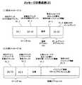
図30(1)は、バインディング要求パケット(以後、BUパケットと略称することがある)81を示しており、このBUパケット81は、IPヘッダ81a、バインディング・アップデート・オプション81b、ホームアドレス・オプション81c、及び認証ヘッダ81dで構成されている。
【0033】
IPヘッダ81aは宛先アドレス(ホームエージェント11のアドレス“10.1”)及び送信元アドレス(端末300のケア・オブ・アドレス=“20.10”)で構成され、オプション81bはシーケンス番号及び有効時間等で構成され、オプション81cは端末300のホームアドレス“10.10”で構成され、認証ヘッダ81dは認証用データ等で構成されている。
【0034】
▲1▼図29のルータ110において、インタフェース10_2は、受信したBUパケット81をパケットスイッチ21へ入力する。
▲2▼ルーティング処理部23は、BUパケット81の宛先アドレス(ホームエージェントのアドレス=“10.1”)を元に、ルーティングテーブル24を検索し、出力先のインタフェースをインタフェース10_1に決定する。
【0035】
図31は、ルーティングテーブル24例を示している。このテーブル24は、宛先プレフィックス、次ホップルータ、そのホップ数、及び出力インタフェースで構成されている。
ルーティング処理部23は、宛先アドレス=“10.1”に対応する宛先プレフィックス“10.x(xはドントケア)”を検索し、このプレフィックスに基づき出力インタフェース10_1を決定する(同図の24a参照)。
【0036】
▲3▼パケットスイッチ21は、BUパケット81をインタフェース10_1へ入力する。
▲4▼インタフェース10_1において、ホームエージェント11は、BUパケット81の宛先アドレスをチェックし、それがホームエージェント11自身であることからBUパケット81を受信する。
【0037】
ホームエージェント11は、BUパケット81の内容を解析し、端末300についてのバインディング情報がバインディング・キャッシュ14(図28参照)に存在しない場合、端末300についてのバインディング情報を生成し、既にバインディング情報が存在していた場合、バインディング・キャッシュ14の情報を更新する。
【0038】
図30(2)は、バインディング・キャッシュ14の構成例を示している。この例では、特に、端末300のバインディング情報例を示しており、このバインディング情報は、移動端末300のホームアドレス=“10.10”、端末300のホームエージェント(HA)11のアドレス=“10.1”、端末300のケア・オブ・アドレス(CoA)=“20.10”、登録有効時間=“300(秒)”、及びセキュリティ情報で構成されている。
【0039】
▲5▼ホームエージェント11は、BUパケット81に対する応答としてバインディング応答パケット(以後、BAパケットと略称することがある。)82を生成し、端末300へ返信するためパケットスイッチ21へ入力する。
図30(3)は、BAパケット82の構成例を示している。このBAパケット82は、IPヘッダ82a、ルーティングヘッダ82b、バインディング・アクノリッジメント・オプション82c、及び認証ヘッダ82dで構成されている。
【0040】
IPヘッダ82aは、宛先アドレス82_1である端末300のケア・オブ・アドレス=“20.10”及び送信元アドレス82_2であるホームエージェントアドレス=“10.1”で構成され、ルーティングヘッダ82bには端末300のホームアドレス82_3=“10.10”が挿入され、オプション82cにはシーケンス番号及び有効時間等82_4が挿入され、認証ヘッダ82dには認証用データ等82_5が挿入されている。
【0041】
▲6▼ルーティング処理部23はBAパケット82の宛先アドレス=“20.10”を元に、ルーティングテーブル24を検索し、出力先のインタフェースをインタフェース10_2に決定する(図31の24b参照)。
▲7▼パケットスイッチ21は、BAパケット82をインタフェース10_2に出力し、インタフェース10_2はBAパケット82をルータ120へ向けて送信する。
【0042】
(5)ルータ内におけるパケット転送動作
図32は、図27に示したパケット転送例のおけるルータ110内部のパケット転送処理例を示している。このパケット転送処理を以下に説明する。
端末310が送信したパケット71は、ルータ130及びリンク240を経由してルータ110へ送信される(図27参照)。
【0043】
図33(1)は、パケット71の構成を示している。このパケット71はIPヘッダ71a及びペイロード71bで構成されている。IPヘッダ71aは宛先アドレス71_1である端末300のホームアドレス=“10.10”と送信元アドレス71_2である端末310のアドレス=“30.11”とで構成されている。
【0044】
▲1▼図32のルータ110において、インタフェース10_3は、パケット71を受信し、このパケット71をパケットスイッチ21に入力する。
▲2▼ルーティング処理部23はパケット71の宛先アドレス=“10.10”を元に、ルーティングテーブル24(図31の24a参照)を検索し、出力先のインタフェースをインタフェース10_1に決定する。
【0045】
▲3▼パケットスイッチ21は、パケット71をインタフェース10_1へ入力する。
▲4▼インタフェース10_1において、ホームエージェント11は、パケット71の宛先アドレス=“10.10”に対応するバインディング情報が存在するか否かを検索する。そして、ホームエージェント11は、端末300についてのバインディング・キャッシュ14(図30(2)参照)が存在することから、パケット71をリンク210へ転送せず、端末300の代わりに受信する。
【0046】
▲5▼ホームエージェント11は、端末300についてのバインディング情報に基づきパケット71をケア・オブ・アドレス=“20.10”でカプセル化したカプセル化パケット72を生成し、このパケット72をパケットスイッチ21へ入力する。
図33(2)は、カプセル化パケット72の構成を示している。このパケット72は、カプセル化ヘッダ72aとペイロード72bとで構成されている。ヘッダ72aは、宛先アドレス72_1である端末300のケア・オブ・アドレス=“20.10”と送信元アドレス72_2であるホームエージェント11のアドレス=“10.1”とで構成され、ペイロード72bにはパケット71がそのまま挿入されている。
【0047】
▲6▼ルーティング処理部23は、パケット72の宛先アドレス=“20.10”を元に、ルーティングテーブル24を検索し、出力先のインタフェースをインタフェース10_2に決定する(図31の24b参照)。
▲7▼パケットスイッチ21は、パケット72をインタフェース10_2へ出力し、インタフェース10_2は、パケット72をルータ120へ向けて送信する。
【0048】
【発明が解決しようとする課題】
図29及び図32に示したように、ホームエージェント11が動作する従来のルータ110においては、常にホームエージェント機能を持つリンクインタフェース10_1において移動中の端末300からのバインディング・アップデートの処理と端末300宛パケット71のカプセル化とが行われる。
【0049】
このため、移動中の端末300宛に多くのパケット71が送信されている場合やホームエージェント11がサポートする端末の数が多い場合には、ホームエージェント11における上記のバインディング・アップデートの処理やカプセル化処理の負荷が高くなり、処理待ちのためのパケット遅延やバッファあふれによるパケット廃棄等が発生する虞れがある。
【0050】
また、ルータ110内において、BUパケット81、BAパケット82、端末300宛パケット71、端末300宛カプセル化パケット72毎に、出力インタフェース決定のためのルーティング処理とその出力インタフェースへの振分処理が行われ、ルーティング処理部23及びパケットスイッチ21の処理能力を浪費することになり、ルータ110全体でのパケット処理スループットを低下させ、やはりパケット遅延やパケット廃棄を引き起こす虞れが有る。
【0051】
移動中の端末300宛パケットの遅延や廃棄が発生した場合、端末300において実行中の通信の品質は劣化してしまう。特に、端末300の移動時にホームエージェント11へ送信されたBUパケット81の処理時間が長い場合、バインディング・キャッシュ14におけるケア・オブ・アドレスの更新も遅くなる。これにより、その間に端末300宛に送信されたパケット71をホームエージェント11は既に端末が移動して居なくなってしまった古いケア・オブ・アドレス宛にカプセル化して転送してしまうことになり、大量のパケット廃棄が発生し、通信品質の劣化だけでなく通信そのものが切断されてしまう虞れがある。
【0052】
従って本発明は、モバイルIPv4/v6が動作するネットワークに接続された移動端末対応ルータにおいて、該移動端末宛のパケットのカプセル化処理及び該移動端末に関するモバイルIPメッセージ処理の処理時間を短縮することにより端末の通信品質劣化の原因となるパケット遅延やパケット廃棄を防ぐことを課題とする。
【0053】
【課題を解決するための手段】
上記の課題を解決するため、本発明の移動端末対応ルータは、移動可能な端末のホームリンクに接続されたホームリンクインタフェースと、該端末の外部リンクに接続された外部リンクインタフェースとを備え、該外部リンクインタフェースが、該端末のバインディング情報を記憶したカプセル化用キャッシュと、該端末宛のパケットを該バインディング情報に含まれるケア・オブ・アドレスでカプセル化すると共に、該カプセル化したパケットをパケット転送ルート経由で、但しルーティング処理部を経由せずに出力インタフェースに送出する処理部と、を有することを特徴としている(請求項1)。
【0054】
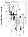
図1は、本発明に係る移動端末対応ルータ100の構成例を示している。このルータ100が、図28に示した従来の移動端末対応ルータ110と異なる点は、移動可能な端末300(図26参照、以後、移動端末300と称することがある。)のホームリンク210以外の、例えば、外部リンク240に接続された外部リンクインタフェース10_3が、カプセル化用キャッシュ12_3及び処理部13を備えていることである。
【0055】
同様に、外部リンク250に接続された外部リンクインタフェース10_2もカプセル化用キャッシュ12_2(以後、キャッシュ12_2,12_3を総称してキャッシュ12と称することがある。)及び処理部13を備えている。
また、ルーティング処理部23がルーティングテーブル24に基づきパケットを転送するパケット転送ルート30とは同じであるが、ルーティングテーブル24を検索せずに直ちにリンクインタフェース10間を相互にパケット転送するルート(同図中の太い破線参照。このルートもパケット転送ルートと称する。このルートについては後述する。)があることも異なっている。
【0056】
なお、図1中のインタフェース10_1〜10_3及び制御部22の間を接続する装置内制御ルート31は、以後の図においては、便宜的に省略することがある。また、ホームエージェント11に含まれるバインディング・キャッシュ14も、以後の図においては、便宜的に省略する。
【0057】
キャッシュ12_3は、バインディング情報として、例えば、図2に示すように、移動端末300のホームアドレス=“10.10”及びケア・オブ・アドレス(CoA)=“20.10”を関連付けて記憶している。これらのホームアドレス及びケア・オブ・アドレスは、例えば、移動端末300宛のパケットをカプセル化するために必要な情報である(付記2)。
【0058】
以後、図26に示したネットワークにおいて、ルータ110を本発明のルータ100に置き換えた場合の動作について説明する。
インタフェース10_3の処理部13は、例えば、移動端末310(図27参照)から送出された移動端末300宛のパケット71をルータ130及び外部リンク240を経由して受信する。そして、処理部13は、受信したパケット71を該バインディング情報に基づき該ケア・オブ・アドレスでカプセル化して送出する。
【0059】
これにより、移動端末300宛のパケット71のカプセル化処理が、インタフェース10_1のホームエージェント11を経由せずに行われることになり、カプセル化処理時間を短縮することが可能になる。
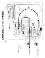
図3は、本発明に係るルータ100の動作原理(1)を示している。ルータ100が、図27で示した端末310が送信した移動端末300宛のパケット71を転送する動作を以下により具体的に説明する。
【0060】
▲1▼端末310が送出したパケット71は、ルータ130を経由してルータ100に到着する。ルータ100のインタフェース10_3がパケット71を受信する。
▲2▼リンクインタフェース10_3において、処理部13_3は、受信したパケット71(図33(1)参照)の宛先アドレス(移動端末300のホームアドレス)=“10.10”に基づき、キャッシュ12_3の情報を検索する(図2参照)。キャッシュ12_3が移動端末300のホームアドレス及びケア・オブ・アドレスを関連付けたバインディング情報を記憶している場合、処理部13_3は、パケット71をケア・オブ・アドレス宛にカプセル化したパケット72(図33(2)参照)を作成する。
【0061】
▲3▼処理部13_3は、パケット72をパケットスイッチ21へ入力する。
▲4▼ルーティング処理部23はパケット72の宛先アドレス(移動端末300のケア・オブ・アドレス)=“20.10”に基づき、ルーティングテーブル24(図31の24b参照)を検索し、出力先インタフェースをインタフェース10_2に決定する。
【0062】
▲5▼パケットスイッチ21は、パケット72をインタフェース10_2に出力する。インタフェース10_2は、パケット72をリンク250を経由してルータ120へ向けて送信する。
上記の▲3▼〜▲5▼の動作に示したように、本発明のルータ100は、カプセル化パケット72をパケットスイッチ21及びパケット転送用バス30を経由してルーティングテーブル24に基づき出力インタフェース10_2に転送することができる。以後、この転送ルートをパケット転送ルート30と称することがある(付記5)。
【0063】
また、本発明では、上記の発明において、該バインディング情報が、自分の有効時間を含むことができる。これにより、移動端末300が、在圏する外部リンクから別に外部リンクに移動した場合、前の外部リンクのバインディング情報を自動的に削除することが可能になる(付記4)。
【0064】
また、本発明では、上記のバインディング情報が、さらに、該カプセル化したパケットを出力する出力インタフェースを該ケア・オブ・アドレスと関連付けることが可能であり(付記3)、このバインディング情報に基づき該処理部が、該カプセル化したパケットを該出力インタフェースに与えることが可能である(付記6)。
【0065】
図4は、本発明に係るルータ100の動作原理(2)を示している。このルータ100が、図3に示したルータ100と異なる点は、キャッシュ12_3が図2に示したキャッシュ12_3の内容に加えて、図5に示すように移動端末300のケア・オブ・アドレス=“20.10”に対応する出力インタフェース10_2を記憶していることである。
【0066】
また、処理部13は、図2に示した処理部13と異なり、カプセル化したパケットをルーティングテーブル24を検索せずに直ちに出力インタフェース10_2に与える。
図4に基づき、ルータ100が移動端末宛パケットを転送する動作手順を以下により具体的に説明する。
【0067】
▲1▼端末310が送出したパケット71は、ルータ130及びリンク240を経由してルータ100へ送信される(図27参照)。ルータ100において、インタフェース10_3は、パケット71を受信する。
▲2▼インタフェース10_3において、処理部13_3は、キャッシュ12_3を検索し、受信したパケット71の宛先アドレス(端末300のホームアドレス)=“10.10”に対応する端末300のケア・オブ・アドレス=“20.10”を得る(図5参照)。そして、処理部13_3は、パケット71をケア・オブ・アドレス=“20.10”宛にカプセル化したカプセル化パケット72を作成する。
【0068】
▲3▼さらに、処理部13は、キャッシュ12_3に基づき端末300のケア・オブ・アドレス=“20.10”に対応するインタフェース10_2を検出し、このインタフェース10_2にパケット72を与える。
▲4▼インタフェース10_2は、パケット72をルータ120へ向けて送信する。
【0069】
これにより、パケット72は、ルーティングテーブル24の検索処理を行うことなく出力インタフェース10_2に直接与えられ、パケット転送ルートの負荷が軽減される。
また、本発明では、上記の発明において、該処理部が該端末からのバインディング要求パケットを受信したとき、該バインディング要求パケットに含まれる該バインディング情報を該カプセル化用キャッシュに記憶することが可能である(請求項2)。
【0070】
すなわち、図6は、本発明に係るルータ100の動作原理(3)を示している。このルータ100において、例えば、移動端末300の外部リンク250に接続されたインタフェース10_2は、上記のインタフェース10_3と同様に、カプセル化用キャッシュ12_2及び処理部13_2を備えている。
【0071】
図7は、キャッシュ12_2が、記憶している内容を示しており、この内容は、ホームエージェント11に含まれるバインディング・キャッシュ14(図1参照)が記憶している移動端末300のバインディング情報と同様である。
図6において、処理部13_2は、移動端末300からのバインディング要求パケット(BUパケット)81を受信してこのバインディング要求パケット81に含まれるバインディング情報でカプセル化用キャッシュ12_2の内容を更新することができる。
【0072】
さらに、本発明では、上記の処理部13_2は、該バインディング要求パケット81に対するバインディング応答パケット82をパケット転送ルート30経由で出力インタフェースに与えることが可能である(付記8)。
すなわち、同図において、処理部13_2は、バインディング要求パケット81に対するバインディング応答パケット82を作成し、このパケット82をパケット転送ルート30経由で、すなわち、パケットスイッチ21を経由して、出力インタフェース10_2に与えることが可能である。
【0073】
移動端末300が、位置登録した場合におけるルータ100のモバイルIPメッセージ処理例を同図を参照して以下に具体的に説明する。
▲1▼リンク220に移動した移動端末300が送信したバインディング要求パケット81(図30(1)参照)は、ルータ120及びリンク250を経由してルータ100にへ送信される(図26参照)。ルータ100において、インタフェース10_2はパケット81を受信する。
【0074】
▲2▼インタフェース10_2において、処理部13_2は、受信したパケット81の種別を解析し、このパケット81がバインディング要求パケットであることを検出する。そこで、処理部13_2は、パケット81に含まれるホームアドレス・オプション81c(図30(1)参照)に示される移動端末300のホームアドレス=“10.10”についてのバインディング情報がキャッシュ12_2に存在するか否かを検索する。
【0075】
キャッシュ12_2に移動端末300のバインディング情報が記憶されている場合、処理部13_2は、パケット81の内容を元にキャッシュ12_2の移動端末300に関するバインディング情報(図7又は図30(2)参照)を更新し、パケット81の応答パケットとしてのバインディング応答パケット82(図30(3)参照)を生成する。
【0076】
▲3▼処理部13_2は、パケット82をパケットスイッチ21に出力する。
▲4▼ルーティング処理部23はパケット82の宛先アドレス(移動端末300のケア・オブ・アドレス)=“20.10”を元に、ルーティングテーブル24(図31参照)を検索し、出力先のインタフェースをインタフェース10_2に決定する。
【0077】
▲5▼パケットスイッチ21は、パケット82をインタフェース10_2に入力し、インタフェース10_2はパケット82をルータ120へ向けて送信する。
このように処理部13_2が、ホームエージェント11の代わりにモバイルIPメッセージ処理を行うことにより、メッセージ処理時間を短縮することが可能になる。
【0078】
また、本発明においては、上記の発明において、該カプセル化用キャッシュが、該バインディング応答パケットを出力する出力インタフェースを該バインディング情報の内の該端末のケア・オブ・アドレスと関連付けて記憶しており、該処理部が、該カプセル化用キャッシュの情報に基づき、該バインディング応答パケットを該出力インタフェースに与えることが可能である(付記9)。
【0079】
図8は、本発明に係るルータ100の動作原理(4)を示している。このルータ100が図6に示したルータ100と異なる点は、インタフェース10_2のキャッシュ12_2が図7に示したバインディング情報の他に、図9に示すように端末300のケア・オブ・アドレス=“20_10”に対応する出力インタフェース10_2をさらに記憶していることである。
【0080】
また、処理部13_2が、キャッシュ12_2を参照して、バインディング要求パケット81に対するバインディング応答パケット82を、出力インタフェース10_2に与えることも異なっている。
以下に、図8に基づき、ルータ100の動作を具体的に説明する。
【0081】
▲1▼リンク220に移動中の端末300が送信したバインディング要求パケット81(図30(1)参照)は、ルータ120及びリンク250を経由してルータ100へ送信される。ルータ100において、インタフェース10_2はパケット81を受信する。
▲2▼インタフェース10_2において、処理部13_2は、受信したパケット81の種別を解析し、このパケット81がバインディング要求パケットであることを検出する。次に、処理部13_2は、パケット81に含まれるホームアドレスオプション81cに示される端末300のホームアドレス=“10.10”についてのバインディング情報がキャッシュ12_2に存在するか否かを検索する。
【0082】
キャッシュ12_2がホームアドレス=“10.10”のバインディング情報を記憶している場合、処理部13_2は、パケット81の内容を元にキャッシュ12_2の更新を行うと共に、パケット81の応答としてのバインディング応答パケット82を生成する(図30(3)参照)。
【0083】
▲3▼処理部13_2は、キャッシュ12_2を参照してパケット82の出力インタフェースであるインタフェース10_2を検索し、このインタフェース10_2にパケット82を装置内制御ルート32を経由して与える。すなわち、パケット82は、インタフェース10_2のパケット受信側から同じインタフェース10_2のパケット送信側に与えられる。
【0084】
▲4▼インタフェース10_2はパケット82をルータ120へ向けて送信する。
これにより、パケット82は、パケットスイッチ21を経由することなくインタフェース10_2に送られ、応答パケットの返送時間の高速化が可能となる。
上記の図3、図4で、それぞれ、説明した本発明の動作原理(1)及び(2)においては、移動端末宛パケットの転送処理の手順を説明し、図6及び図8で、それぞれ説明した本発明の動作原理(3)及び(4)においては、モバイルIPメッセージの交換処理及びカプセル化用キャッシュのバインディング情報の取得について説明した。
【0085】
以下に、図10、図12、及び図14〜図19で、それぞれ、説明する本発明の動作原理(5)〜(12)においては、外部リンクインタフェースが、移動端末宛のパケット又は移動端末からのパケットを受信したとき、カプセル化用キャッシュが該移動端末のバインディング情報を記憶していない場合、ホームエージェントから、図2、図5、図7、及び図9に示したバインディング情報(キャッシュ情報と称することがある。)を取得する手順を説明する。
【0086】
なお、本発明の動作原理(5)〜(12)における本発明に係る移動端末対応ルータ100の基本的な構成は、図1に示した移動端末対応ルータ100と同様である。
また、本発明の移動端末対応ルータ100では、上記の発明において、該処理部は、該端末に係るパケットを受信したとき、該カプセル化用キャッシュが該端末のバインディング情報を記憶していない場合、ホームエージェントから該バインディング情報を取得することが可能である(請求項3)。
【0087】
なお、上記の該端末に係るパケットには、該端末宛のパケット及び該端末からのバインディング要求パケットが含まれる(付記11及び付記12)。
すなわち、図1において、移動端末300に対する外部リンクインタフェース10_3の処理部13_3は、端末300に係るパケット、例えば、端末300宛のパケットを受信したとき、キャッシュ12_3が端末300のバインディング情報を記憶していない場合、受信したパケットをカプセル化できない。
【0088】
このような場合、処理部13_3は、ホームエージェントから端末300に関するバインディング情報を取得してキャッシュ12_3に書き込むことが可能である。
これにより、キャッシュ12_3は、端末300に関するバインディング情報を取得・記憶することが可能になり、処理部は、端末に係るパケットを受信した場合、そのカプセル化が可能になる。
【0089】
また、本発明においては、上記の発明において、該処理部は、該バインディング情報を記憶していないことを要求メッセージで該ホームエージェントに通知しすることができる(請求項4)。
図10は、本発明の移動端末対応ルータ100の動作原理(5)を示している。この原理(5)では、リンクインタフェース10_3からホームエージェント11に対して移動端末300のケア・オブ・アドレスを要求する旨のメッセージを通常のパケットと同様の転送方法により送信する。
【0090】
ここで、キャッシュ12_3は、バインディング情報を何も記憶していない状態であるものとする。
▲1▼端末310が送信したパケット71(図33(1)参照)は、ルータ130を経由してルータ100に到着する。ルータ100において、インタフェース10_3が、パケット71を受信する。
【0091】
▲2▼インタフェース10_3において、処理部13_3は受信したパケット71の宛先アドレス(端末300のホームアドレス=10.10)を元に、キャッシュ12_3の情報を検索する。キャッシュ12_3が宛先アドレスについてのバインディング情報(ケア・オブ・アドレス)を記憶していない場合、処理部13_3はホームエージェント11にケア・オブ・アドレスを要求するための要求メッセージ73を生成する。
【0092】
図11(1)は、要求メッセージ73の構成例を示している。この要求メッセージ73は、IPヘッダ73a及び新規オプション73bで構成され、IPヘッダ73aは、パケット71の宛先アドレス73_1=端末300のホームアドレス“10.10”とパケット71の送信元アドレス73_2=端末310のアドレス“30.11”とで構成され、新規オプション73bには、「要求メッセージであることの表示73_3」、すなわち、「要求内容が“ケア・オブ・アドレス”であること」が表示される。
【0093】
▲3▼処理部13_3は、受信したパケット71と生成した要求メッセージ73をパケットスイッチ21へ入力する。
▲4▼,▲4▼'以後、パケット71及び要求メッセージ73は、図32で示したパケット転送ルート30で、インタフェース10_1に転送される。
【0094】
すなわち、▲4▼ルーティング処理部23はパケット71及び要求メッセージ73の宛先アドレス(いずれも端末300のホームアドレス=10.10)を元に、ルーティングテーブル24(図31参照)を検索し、出力先のインタフェースをインタフェース10_1に決定する。▲4▼'パケットスイッチ21は、パケット71及び要求メッセージ73をインタフェース10_1へ入力する。
【0095】
この内の要求メッセージにより、インタフェース10_3の処理部13_3は、端末300のバインディング情報がキャッシュ12_3に記憶されていないことをホームエージェント11に通知できる。
次に、ホームエージェント11が、バインディング情報を処理部13_3に通知する手順を説明する。
【0096】
すなわち、本発明では、上記の発明において、ホームエージェント11は、カプセル化用キャッシュ12_3が該バインディング情報を記憶していないことを示す通知を受信したとき、自分が保持するバインディング・キャッシュから必要な情報を処理部13_3に通知することが可能である(付記17)。
【0097】
▲5▼ホームエージェント11は、パケット71の宛先アドレスと、これに対するバインディング・キャッシュが存在するかどうかをチェックする。そして、端末300についてのバインディング・キャッシュ(図30(2)参照)が存在することから、ホームエージェント11は、パケット71をリンク210へ転送せずに端末300の代わりに受信し、端末300についてのバインディング・キャッシュに基づきパケット71をケア・オブ・アドレス=“20.10”でカプセル化する。
【0098】
また、ホームエージェント11は受信した要求メッセージ(パケット)73の種別を解析し、入力されたパケット73が要求メッセージであることを検出する。そしてこの要求メッセージの内容に基づき、端末300についてのバインディング・キャッシュから端末300のケア・オブ・アドレス=“20.10”をインタフェース10_3に通知するための応答メッセージ74を生成する。
【0099】
図11(2)は、応答メッセージ74の構成例を示している。この応答メッセージ74は、IPヘッダ74a及び新規オプション74bで構成されている。IPヘッダ74aは、宛先アドレス(パケット71の送信元アドレス)74_1と送信元アドレス(パケット71の宛先アドレス)74_2から成り、新規オプション74bは、「応答メッセージであることの表示74_3」と「移動端末300のケア・オブ・アドレス74_4」とから成っている。
【0100】
なお、図11(1)及び(2)に示したメッセージは、本発明のルータ100内で独自に交換されるものであるため、IPの標準では定義されていない独自の新規オプションを用いている。
ここで、ホームエージェント11は、要求メッセージ73の送信元のアドレス(ここでは“30.11”)記憶しておく。これは、後にホームエージェント11が、例えば端末300からのバインディング要求パケットを受信し、バインディング情報(ケア・オブ・アドレス)が変更された場合、この情報を外部リンクインタフェース10_3に送信するためである(付記21)。
【0101】
なお、ホームエージェント11は、送信元のアドレス=“30.11”を元にルーティングテーブル24(図31参照)を検索することにより、外部リンクインタフェース10_3を特定する。
▲6▼ホームエージェント11は、パケット72及び応答メッセージ74をパケットスイッチ21に入力する。
【0102】
▲7▼,▲7▼',▲7▼"パケット72及び応答メッセージ74は、パケット転送ルート30で、それぞれ、インタフェース10_2及びインタフェース10_3に転送される。
すなわち、▲7▼ルーティング処理部23は、パケット72の宛先アドレス=端末300のケア・オブ・アドレス“20.10”を元に、ルーティングテーブル24(図31参照)を検索し、出力先のインタフェースをインタフェース10_2に決定する。
【0103】
また、ルーティング処理部23は、応答メッセージ74の宛先アドレス=パケット71の送信元アドレス“30.11”を元に、ルーティングテーブル24を検索し、出力先のインタフェースをインタフェース10_3に決定する。
▲7▼'パケットスイッチ21は、パケット72をインタフェース10_2へ入力する。インタフェース10_2はパケット72をルータ120へ向けて送信する。
【0104】
▲7▼"パケットスイッチ21は、応答メッセージ74をインタフェース10_3へ入力する。
▲8▼インタフェース10_3において、処理部13_3は、入力された応答メッセージ(パケット)74の種別を解析し、このパケット74が応答メッセージであることを検出する。そして、処理部13_3は、応答メッセージ74の内容に基づき、ホームエージェント11から通知された端末300のケア・オブ・アドレス=“20.10”をキャッシュ12_3に記憶する。
【0105】
このように、ホームエージェント11は、応答メッセージ74で該バインディング情報をパケット転送ルート30を経由して通知することが可能である(付記18)。
上記のキャッシュ12_3の情報取得処理により、インタフェース10_3には図2に示したキャッシュ内容が生成される。以後、処理部13_3は、このキャッシュ内容が記憶されている間は、端末300宛パケット71を図3に示したように転送処理することが可能となる。
【0106】
図12は、本発明に係るルータ100の動作原理(6)を示している。この原理(6)が図10に示した原理(5)と異なる点は、外部リンクインタフェースが、移動端末300宛パケット71の代わりに、移動端末300からのバインディング要求パケット81を受信したとき、図10と同様の動作で、ホームエージェント11に対して端末のバインディング情報を要求する旨の要求メッセージをパケット転送ルート30を経由して送信する。
【0107】
ここで、キャッシュ12_2は、バインディング情報を何も記憶していない状態であるとする。
以下に、動作原理(6)に基づくキャッシュ情報の取得例をより具体的に説明する。
【0108】
▲1▼端末300が送信したバインディング要求パケット81(図30(1)参照)は、ルータ120を経由してルータ100へ送信され、ルータ100において、インタフェース10_2がパケット81を受信する。
▲2▼インタフェース10_2において、処理部13_2は受信したパケット81の種別を解析し、このパケット81がバインディング要求パケットあることを検出する。次に、処理部13_2は、パケット81に含まれるホームアドレス・オプション81cに示された端末300のホームアドレス=“10.10”についてのバインディング情報がキャッシュ12_2に存在するかを検索する。
【0109】
キャッシュ12_2に端末300のバインディング情報が記憶されていない場合には、処理部13_2はホームエージェント11に端末300のバインディング情報を要求するための要求メッセージ83を生成する。
図13(1)は、要求メッセージ83の構成例を示しており、この要求メッセージ83は、IPヘッダ83a、新規オプション83b、及びホームアドレス・オプション83cで構成されている。IPヘッダ83aは、バインディング要求パケット81の宛先アドレス83_1=“10.1”及び送信元アドレス83_2=“20.10”から成り、新規オプション83bは、「要求メッセージであることの表示83_3」から成り、ホームアドレスオプション83cは、「移動端末300のホームアドレス83_4」=“10.10”から成っている。
【0110】
このように本発明では、処理部は、移動端末からのバインディング要求パケット81を受信した場合においてもホームエージェント11に対して要求メッセージ83でバインディング情報を要求することができる(請求項4、付記12)。
▲3▼処理部13_3は、受信したバインディング要求パケット81と生成した要求メッセージ83とをパケットスイッチ21へ入力する。
【0111】
▲4▼,▲4▼'以後、バインディング要求パケット81及び要求メッセージ83は、図10に示した発明の原理(5)と同様に、パケット転送ルート30でインタフェース10_1に送信される。すなわち、バインディング要求パケット81及び要求メッセージ(パケット)83の宛先アドレスは共に同じホームエージェント11のアドレス=“10.1”であるので、パケット81,83は、共にパケット転送ルート30を経由してインタフェース10_1に入力される。
【0112】
▲5▼インタフェース10_1において、ホームエージェント11はパケット81の宛先アドレスをチェックし、ホームエージェント11自身であることからパケット81を受信する。ホームエージェント11は、パケット81の内容を解析し、バインディング・キャッシュ14に端末300についてのバインディング情報(図30(2)参照)を生成する。なお、既にバインディング・キャッシュ14に端末300についてのバインディング情報が存在していた場合には、バインディング情報を更新する。
【0113】
そして、ホームエージェント11はバインディング要求パケット81に対する応答パケットとしてバインディング応答パケット82を生成する。
また、同様に、ホームエージェント11は受信した要求メッセージ(パケット)83の種別を解析し、パケット83が要求メッセージであることを検出する。そして、ホームエージェント11は、要求メッセージ83の内容に基づき、端末300についてのバインディング情報をインタフェース10_2に通知するための応答メッセージ84を生成する。
【0114】
図13(2)は、応答メッセージ84の構成を示している。この応答メッセージ84は、IPヘッダ84a及び新規オプション84bで構成されている。IPヘッダ84aは宛先アドレス84_1=パケット71の送信元アドレス“20.10”及び送信元アドレス84_2=パケット71の宛先アドレス=“10.1”から成り、新規オプション84bは、「応答メッセージであることの表示84_3」及びバインディング情報84_4から成っている。
【0115】
なお、図13(1)及び(2)に示したメッセージは、ルータ内で独自に交換されるものであるため、それぞれ、IPの標準では定義されていない独自の新規オプション83b及び84bを用いている。
また、ホームエージェント11は、後に、端末300のバインディング情報が変更された場合にそれを通知するために、要求メッセージ83の送信元アドレス(ここでは“20.10”)を記憶しておく(付記21)。
【0116】
▲6▼インタフェース10_1は、バインディング応答パケット82及び応答メッセージ84をパケットスイッチ21へ入力する。
▲7▼,▲7▼',▲7▼"バインディング応答パケット82及び応答メッセージ84は、共にパケット転送ルート30でインタフェース10_2に送信される。インタフェース10_2はパケット82をルータ120へ向けて送信する。
【0117】
▲8▼インタフェース10_2において、処理部13_2は、入力された応答メッセージ(パケット)84に含まれる表示84_3を検出し、パケット84が応答メッセージであることを認識する。そして、処理部13_2は、応答メッセージの内容に基づき、ホームエージェント11から通知された端末300のバインディング情報84_4をキャッシュ12_2に記憶する。
【0118】
上記の処理により、キャッシュ12_2には、図7に示したような移動端末300に関するバインディング情報が生成される。以後、このバインディング情報が記憶されている間、処理部13_2は、端末300から周期的にホームエージェント11宛に送信されるバインディング要求パケット81を図6に示した動作原理(3)の処理を行うことが可能となる。
【0119】
図14は、本発明に係るルータ100の動作原理(7)を示している。この原理(7)ではキャッシュの情報取得方法の別の例を示している。該処理部は、通常のルーティングによるパケット転送ルート30ではなく、装置内制御ルート32を経由してホームエージェント11から該バインディング情報を獲得する方法を示す(請求項3、付記15)。
【0120】
ここで、キャッシュ12_3は、バインディング情報を何も記憶していない状態であるとする。
▲1▼端末310が送信したパケット71は、ルータ130を経由してルータ100へ送信される。ルータ100において、インタフェース10_3はパケット71を受信する。
【0121】
▲2▼インタフェース10_3において、処理部13_3は受信したパケット71の宛先アドレス=端末300のホームアドレス“10.10”を元に、キャッシュ12_3のバインディング情報を検索する。
▲3▼処理部13_3は、キャッシュ12_3がパケット71の宛先アドレスに関するバインディング情報(ケア・オブ・アドレス)が記憶されていない場合には、受信したパケット71をパケットスイッチ21に入力する。
【0122】
▲4▼,▲4▼’パケット71は、パケット転送ルート30でインタフェース10_1に入力される。
▲5▼インタフェース10_1において、ホームエージェント11は、パケット71の宛先アドレスと、これに対するバインディング・キャッシュが存在するかどうかをチェックする。そして端末300についてのバインディング・キャッシュ(図30(2)参照)が存在することから、ホームエージェント11はパケット71をリンク210へ転送せずに端末300の代わりに受信し、端末300についてのバインディング情報に基づきパケット71をケア・オブ・アドレスでカプセル化したパケット72を生成する。
【0123】
▲6▼ホームエージェント11はパケット72をパケットスイッチ21へ入力する。
▲7▼,▲7▼'パケット72は、パケット転送ルート30でインタフェース10_2に入力される。インタフェース10_2はパケット72をルータ120へ向けて送信する。
▲8▼インタフェース10_3において、処理部13_3は、▲3▼において、キャッシュがパケット71の宛先アドレスについてのバインディング情報(ケア・オブ・アドレス)を記憶していなかったため、装置内制御ルート32を使用してケア・オブ・アドレスの取得を試みる。
【0124】
まず、処理部13_3は、制御バス31経由でルーティングテーブル24(図31参照)を参照し、パケット71(図33参照)の宛先アドレス=“10.10”に対する出力インタフェースがインタフェース10_1であることを知る(図31の24a参照)。
このように、本発明では、該処理部が、例えば、制御バス31を経由してルーティングテーブルから必要な情報(ここでは、出力インタフェース情報)を獲得することができる(付記16)。
【0125】
次に、処理部13_3は、インタフェース10_1のホームエージェント11に対して、バインディング・キャッシュ14にパケット71の宛先アドレス=“10.10”についてのバインディング情報を保持しているかを確認し、保持している場合にはバインディング情報からケア・オブ・アドレス=“20.10”を取得する。
【0126】
さらに、処理部13_3は、取得したケア・オブ・アドレスを元に再度ルーティングテーブル24を参照し、ケア・オブ・アドレス=“20.10”に対する出力インタフェース(ここではインタフェース10_2)の情報も併せて取得し(同図の24b参照)、キャッシュ12_3に記憶する。
【0127】
なお、ホームエージェント11は、後に、端末300のケア・オブ・アドレスが変更された場合にそれを通知するため、ケア・オブ・アドレスの取得を行ったインタフェースであるインタフェース10_3を記憶しておく(付記21)。
上記の処理により、インタフェース10_3のキャッシュ12_3には図5に示したようなバインディング情報が生成される。以後、このバインディング情報が記憶されている間、処理部13_3は、端末300宛のパケット71を図4に示した原理(2)のように処理することが可能となる。
【0128】
図15は、本発明に係るルータ100の動作原理(8)を示しており、キャッシュの情報取得方法の別の例を示す。この例では処理部は、図14に示した原理(7)と異なり、移動端末宛パケットの代わりに移動端末からのバインディング要求パケットを受信したことを契機として、図14と同様に装置内制御ルート32を使用して、キャッシュにバインディング情報を取得する(請求項3、付記12、及び付記15)。
【0129】
ここで、キャッシュ12_2は、バインディング情報を何も記憶していない状態であるとする。
▲1▼端末300が送信したバインディング要求パケット81(図30(1)参照)が、ルータ120を経由してルータ100へ送信される。ルータ100において、インタフェース10_2はパケット81を受信する。
【0130】
▲2▼インタフェース10_2において、処理部13_2は、パケット81の種別を解析し、このパケット81がバインディング要求パケットであることを検出し、次にパケット81に含まれるホームアドレス・オプション81cに示される端末300のホームアドレス=“10.10”についてのバインディング情報がキャッシュ12_2に存在するかを検索する。
【0131】
▲3▼処理部13_2は、キャッシュ12_2が端末300に関するバインディング情報を記憶していない場合、受信したバインディング要求パケット81をパケットスイッチ21へ入力する。
▲4▼,▲4▼'パケット81は、パケット転送ルート30を経由してインタフェース10_1に転送される。
【0132】
▲5▼インタフェース10_1において、ホームエージェント11は、パケット81の宛先アドレスをチェックし、ホームエージェント自身であることからパケット81を受信する。ホームエージェント11は、パケット81の内容を解析し、端末300についてのバインディング・キャッシュ(図30(2)参照)を生成する。(既に、端末300についてのバインディング・キャッシュが存在していた場合には、バインディング・キャッシュの情報を更新する。)そして、ホームエージェント11は、バインディング要求パケット81に対する応答としてバインディング応答パケット82を生成する。
【0133】
▲6▼ホームエージェント11は、パケット82をパケットスイッチ21へ入力する。
▲7▼,▲7▼'パケット82は、パケット転送ルート30を経由してインタフェース10_2に転送される。インタフェース10_2はパケット82をルータ120へ向けて送信する。
▲8▼インタフェース10_2において、処理部13_2は、上記の▲3▼において、キャッシュ12_2がバインディング要求パケット82の送信元である端末300についてのバインディング情報(ケア・オブ・アドレス)を記憶していなかったため、装置内制御ルート32を使用してバインディング情報の取得を試みる。
【0134】
すなわち、処理部13_2は、ルーティングテーブル24(図31参照)を参照し、パケット81の宛先であるホームエージェント11のアドレス“10.1”に対する出力インタフェースがインタフェース10_1であることを知る(同図の24a参照)。
次に、処理部13_2は、インタフェース10_1のホームエージェント11に対して、バインディング・キャッシュ14が端末300についてのバインディング情報を保持しているかを確認し、保持している場合には端末300のバインディング情報を取得する。さらに、処理部13_2は、端末300からのパケット81を取得した処理部13_2自身を含むインタフェース10_2の情報も併せて取得し、キャッシュ12_2に記憶する。
【0135】
なお、ホームエージェント11は、後に端末300のバインディング・キャッシュが変更された場合にそれをインタフェース10_2に通知するため、バインディング情報の取得を行ったインタフェースであるインタフェース10_2を記憶しておく(付記21)。
【0136】
上記の処理により、キャッシュ12_2には、図9に示したような移動端末300に関するバインディング情報が生成される。以降、このバインディング情報が記憶されている間、処理部13_2は、端末300から周期的にホームエージェント11宛に送信されるバインディング要求パケット81を図8のように処理することが可能となる。
【0137】
図16は、本発明に係るルータ100の動作原理(9)を示している。この原理(9)では、キャッシュの情報取得方法の別例を示す。外部リンクインタフェース10_3の処理部13_3は、キャッシュ12_3が移動端末300に関するバインディング情報を記憶していない場合、受信した移動端末300宛のパケット71に、自身が属するリンクインタフェース10_3の識別子を付与したパケット71をパケット転送ルート30を経由してホームエージェント11に送信する。
【0138】
ホームエージェント11は、識別子が付与されたパケット71を受信したとき、リンクインタフェース10_3の処理部13_3が端末300に関するバインディング情報を要求していることを認識する(請求項3、請求項5、及び付記11)。
ここで、キャッシュ12_3は、端末300に関するバインディング情報を何も記憶していない状態であるとする。
【0139】
▲1▼端末310が送信したパケット71(図33(1)参照)は、ルータ130を経由してルータ100へ送信される。ルータ100において、インタフェース10_3はパケット71を受信する。
▲2▼インタフェース10_3において、処理部13_3は、受信したパケット71の宛先アドレス=端末300のホームアドレス“10.10”を元に、キャッシュ12_3のバインディング情報を検索する。キャッシュ12_3が宛先アドレスについてバインディング情報(ケア・オブ・アドレス)を記憶していない場合、処理部13_3はパケット71をカプセル化できない、そこで、パケット71にインタフェース10_3の識別子75=“#3”の付与のみ行う。
【0140】
▲3▼処理部13_3は、パケット71をパケットスイッチ21に入力する。
▲4▼,▲4▼'パケット71は、パケット転送ルート30を経由してインタフェース10_1に送信される。
▲5▼インタフェース10_1において、ホームエージェント11は、パケット71の宛先アドレスである端末300のホームアドレス=“10.10”に対するバインディング情報がバインディング・キャッシュ14に存在するか否かをチェックする。
【0141】
そして、ホームエージェント11は、端末300についてのバインディング情報(図30(2))が存在することから、パケット71をリンク210へ転送せずに端末300の代わりに受信し、端末300についてのバインディング情報に基づきパケット71に自身が属するインタフェース10_1の識別子=“#1”を付与した後、ケア・オブ・アドレスでカプセル化したパケット72を生成する(付記20)。
【0142】
なお、ホームエージェント11がパケット71に自身が属するインタフェース10_1の識別子=“#1”を付与する理由は、通常、ホームエージェント11と処理部13_3との動作は同じ機能ブロックで行うようにするため、処理部13_3で行われる識別子付与をホームエージェント11でも行っている。
【0143】
この様な識別子付与を行う代わりにホームエージェント11は、受信したパケット71に含まれる識別子75=“#3”を削除した後、パケット71をケア・オブ・アドレスでカプセル化してもよい。この場合、処理部13_2はパケット72から識別子76=“#1”を削除する必要はない。
【0144】
さらに、ホームエージェント11は、受信したパケット71の宛先アドレスを持つ端末300のバインディング情報(ケア・オブ・アドレス)をインタフェース10_3に通知するための応答メッセージ74を生成する。
なお、インタフェース10_1では、後に端末300のケア・オブ・アドレスが変更された場合にそれを通知するため、パケット71の入力元インタフェース(ここではインタフェース10_3)の識別子を記憶しておく(付記21)。
【0145】
▲6▼ホームエージェント11は、パケット72をパケットスイッチ21へ入力する。
▲7▼,▲7▼'パケット72は、パケット転送ルートを経由してインタフェース10_2に送信される。インタフェース10_2において、処理部13_2はパケット72に付与された入力元インタフェース(ここではインタフェース10_1)の識別子76=“#1”を削除し、ルータ120へ向けて送信する。
【0146】
▲8▼ホームエージェント11は、パケット71に付与されている識別子に基づき、▲5▼で生成した応答メッセージ(パケット)74を、パケット転送ルート30を経由してインタフェース10_3へ入力する。
▲9▼インタフェース10_3において、処理部13_3は、入力されたパケットの種別を解析し、入力されたパケット74が応答メッセージであることを検出する。そして、処理部13_3は応答メッセージの内容に基づき、ホームエージェント11から通知された端末300のバインディング情報(ケア・オブ・アドレス)をキャッシュ12_3に記憶する。
【0147】
上記の処理により、キャッシュ12_3には図2に示したようなバインディング情報が生成される。以後、このバインディング情報が記憶されている間、処理部13_3は、端末300宛のパケット71は図3に示した原理(1)の転送処理を行うことが可能となる。
【0148】
図17は、本発明に係るルータ100の動作原理(9)を示しており、この原理(9)では、キャッシュへの情報取得方法の別の例を示している。この例が図16に示した原理(8)と異なる点は、外部リンクインタフェースが、移動端末300宛パケット71の代わりに移動端末300からバインディング要求パケット81を受信したことを契機として、リンクインタフェースの識別子を付与したパケット81をパケット転送ルート30を経由してホームエージェント11に送信することにより、ホームエージェント11に対して端末300に関するバインディング情報を要求することである(請求項3、請求項5、及び付記12)。
【0149】
ここで、キャッシュ13_2は、端末300のバインディング情報を何も記憶していない状態であるとする。
▲1▼端末300が送出したバインディング要求パケット81(図30(1)参照)は、ルータ120を経由してルータ100へ送信される。ルータ100において、インタフェース10_2はパケット81を受信する。
【0150】
▲2▼インタフェース10_2において、処理部13_2は、受信したパケット81の種別を解析し、このパケット81がバインディング要求パケットであることを検出する。次に、処理部13_2は、パケット81に含まれるホームアドレス・オプション81cに示された端末300のホームアドレス=“10.10”に関するバインディング情報がキャッシュ12_2に存在するか否かを検索する。
【0151】
キャッシュ12_2が端末300に関するバインディング情報(ケア・オブ・アドレス)が記憶されていない場合、処理部13_2はバインディング要求パケット81を自身では処理せずに、パケット81にインタフェース10_2の識別子85=“#2”の付与のみ行う。
【0152】
▲3▼処理部13_2は、パケット81をパケットスイッチ21へ入力する。
▲4▼,▲4▼'パケット81は、パケット転送ルート30経由でインタフェース10_1に送信される。
▲5▼インタフェース10_1において、ホームエージェント11は、パケット81の宛先アドレスをチェックし、宛先がホームエージェント11自身であることからパケット81を受信する。ホームエージェント11は、パケット81の内容を解析し、バインディング・キャッシュ14に端末300についてのバインディング情報(図30(2)参照)を生成する。なお、既に端末300についてのバインディング情報が存在していた場合、ホームエージェント11は、端末300に関するバインディング情報を更新する。
【0153】
そして、ホームエージェント11は、バインディング要求パケット81に対する応答として、自身が属するインタフェース10_1の識別子=“#1”を付与したバインディング応答パケット82を生成すると共に、端末300のバインディング情報をインタフェース10_3に通知するための識別子85=“#1”を付与した応答メッセージ84を生成する(付記20)。
【0154】
なお、ここで、ホームエージェント11は、後に端末300のバインディング・キャッシュが変更された場合にそれを通知するため、バインディング要求パケットの入力元インタフェース(ここではインタフェース10_2)の識別子を記憶しておく(付記21)。
【0155】
▲6▼ホームエージェント11は、生成したパケット82をパケットスイッチ21に入力する。
▲7▼,▲7▼'パケット82は、パケット転送ルート30を経由してインタフェース10_2に送信される。インタフェース10_2において、処理部13_2は、パケット82に付与された識別子=“#1”を削除した後、パケット82をルータ120に向けて送信する。
【0156】
▲8▼ホームエージェント11は、パケット81に付与された識別子85=“#2”に基づき、▲5▼で生成した応答メッセージ(パケット)84を、パケット転送ルートでインタフェース10_2に入力する。
▲9▼インタフェース10_2において、処理部13_2は、パケット84の種別を解析し、パケット84が応答メッセージであることを検出する。そして、処理部13_2は、この応答メッセージ84の内容に基づき、ホームエージェント11から通知された端末300のバインディング情報(ケア・オブ・アドレス)をキャッシュ12_2に記憶する。
【0157】
上記の処理により、キャッシュ12_2には図7に示したようなバインディング情報が記憶される。以降、このバインディング情報が記憶されている間は、端末300宛のバインディング要求パケット81は図6のように処理することが可能となる。
【0158】
図18は、本発明に係るルータ100の動作原理(11)を示している。この原理(11)ではキャッシュの情報取得方法の別の例を示している。図16に示した原理(9)と同様に、処理部13_3は、キャッシュ12_3が移動端末300に関するバインディング情報を記憶していない場合、受信した移動端末300宛のパケット71に自分が属するリンクインタフェース10_3の識別子=“#3”を付与したパケット71をパケット転送ルート30を経由してホームエージェント11に送信する(請求項3、請求項5、及び付記11)。
【0159】
この例が原理(9)と異なる点は、処理部13_3が、装置内制御ルート経由でホームエージェント11に対して端末300に関するバインディング情報を要求することである(付記15)。
ここで、キャッシュ12_3は、端末300に関するバインディング情報を何も記憶していない状態であるとする。
【0160】
▲1▼〜▲3▼,▲4▼,▲4▼'は、図16に示した原理(9)における▲1▼〜▲3▼,▲4▼,▲4▼'と同様である。
▲5▼ホームエージェント11は、パケット71の宛先アドレス=移動端末300のホームアドレス“10.10”に対応するバインディング情報が、バインディング・キャッシュ14が存在するか否かをチェックする。そして、ホームエージェント11は、端末300に関するバインディング情報が存在することから、パケット71をリンク210へ転送せずに端末300の代わりに受信し、端末300についてのバインディング情報に基づきパケット71をケア・オブ・アドレスでカプセル化したパケット72を生成する。
【0161】
なお、ホームエージェント11は、後に端末300のケア・オブ・アドレスが変更された場合にそれを通知するため、パケット71の入力元インタフェース(ここではインタフェース10_3)の識別子を記憶しておく(付記21)。
▲6▼,▲7▼,▲7▼'は、図16に示した原理(9)の説明における▲6▼,▲7▼,▲7▼'と同様である。
【0162】
▲8▼ホームエージェント11は、パケット71に付与されたインタフェース10_3の識別子=“#3”に基づき、端末300のバインディング情報(ケア・オブ・アドレス)を装置内制御ルートを経由してインタフェース10_3に通知する(付記19)。さらに、ホームエージェント11は、例えば、制御用バス31を経由してルーティングテーブル24(図31参照)を参照し、端末300のケア・オブ・アドレス=“20.10”に対する出力インタフェース(外部インタフェース10_2)の情報もインタフェース10_3に通知する(付記16)。
【0163】
▲9▼インタフェース10_3において、処理部13_3は、ホームエージェント11から通知された内容に基づき、端末300のバインディング情報及び出力インタフェース10_2をキャッシュ12_3に記憶する。
上記の処理により、キャッシュ12_3には図5に示したバインディング情報が生成される。以後、このバインディング情報が記憶されている間、処理部13_3は、端末300宛パケット71を図4のように転送処理することが可能となる。
【0164】
図19は、本発明に係るルータ100の動作原理(12)を示しており、この原理(12)では、キャッシュの情報取得方法の別例を示している。この例では図17に示した原理(10)と同様に、外部リンクインタフェース10_2が、キャッシュ12_3が移動端末300に関するバインディング情報を記憶していない場合、バインディング要求パケット81を受信したことを契機として、リンクインタフェース10_2の識別子=“#2”を付与したパケット81をパケット転送ルート30を経由してホームエージェント11に送信することにより、ホームエージェント11に対して端末300に関するバインディング情報を要求する(請求項3、請求項5、及び付記12)。
【0165】
また、ホームエージェント11は、端末300に関するバインディング情報を入力元のインタフェース10_2に対して、原理(10)とは異なりパケット転送ルート30の代わりに、装置内制御ルート32を経由して通知する(付記19)。
ここで、キャッシュ12_2は、移動端末300のバインディング情報を何も記憶していない状態であるとする。
【0166】
▲1▼〜▲3▼,▲4▼,▲4▼'は、図17に示した原理(10)の説明における▲1▼〜▲3▼,▲4▼,▲4▼'と同様である。
▲5▼ホームエージェント11は、パケット81の宛先アドレスをチェックし、ホームエージェント11自身であることからパケット81を受信し、パケット81の内容を解析し、バインディング・キャッシュ14に端末300に関するバインディング情報を生成する(既に、端末300についてのバインディング・キャッシュ14が存在していた場合には、端末300に関するバインディング情報を更新する)。
【0167】
そして、ホームエージェント11は、バインディング要求パケット81に対する応答としてバインディング応答パケット82を生成する。
ここで、ホームエージェント11は、後に端末300のバインディング・キャッシュが変更された場合にそれを通知するため、バインディング要求パケット81の入力元インタフェース(ここではインタフェース10_2)の識別子=“#2”を記憶しておく(付記21)。
【0168】
▲6▼,▲7▼,▲7▼'は、図17に示した原理(10)の説明における▲6▼,▲7▼,▲7▼'と同様である。
▲8▼ホームエージェント11は、バインディング要求パケット81に付与された識別子87=“#2”に基づき、制御ルート32経由でインタフェース10_2に移動端末300のバインディング情報を通知する。
【0169】
▲9▼インタフェース10_2において、処理部13_3は、インタフェース10_1から通知されたパケット84に含まれる端末300のバインディング情報をキャッシュ12_2に記憶する。さらに、処理部13_3は、端末300のケア・オブ・アドレスに対応する出力インタフェースとして自身が属するインタフェース10_2情報もバインディング情報と共にキャッシュ12_2に記憶する。
【0170】
上記の処理により、キャッシュ12_2には図9に示したようなバインディング情報が生成される。以降、このバインディング情報が記憶されている間、処理部13_2は、端末300宛のバインディング要求パケット81を図8のように処理することことが可能になる。
【0171】
さらに、本発明に係る移動端末対応ルータは、移動可能な端末のホームリンクに接続されたホームリンクインタフェースと、該端末の外部リンクに接続された外部リンクインタフェースとを備え、該外部リンクインタフェースが、該端末のホームエージェントの代わりにモバイルIPメッセージの交換を行う処理部と、該メッセージに含まれる該端末のバインディング情報を記憶したキャッシュとを有することを特徴としている(付記22)。
【0172】
すなわち、本発明のルータの構成は、図1に示した構成と同様であるが、同図に示したの外部リンクインタフェース10の処理部13及びキャッシュ12がホームエージェント11及びこれに含まれるバインディング・キャッシュ14と同じ機能を果たすことが異なっている。
【0173】
すなわち、処理部13は、ホームエージェントの代わりに移動端末とモバイルIPメッセージの交換を行い、キャッシュ12は該メッセージに含まれる該移動端末のバインディング情報を記憶することが可能である。
なお、上記のモバイルIPメッセージとして、例えば、該端末から受信したバインディング要求パケット及びこの要求パケットに対するバインディング応答パケットを交換することが可能である(付記23)。
【0174】
また、処理部は、バインディング応答パケット(BAパケット)を、図8又は図9に、それぞれ示したように、パケット転送ルート及び装置内制御ルートの内のいずれかで転送することができる。
これにより、ホームエージェントは、モバイルIPメッセージの交換を行う必要がなくなりメッセージ交換の高速化が可能になる。
【0175】
また、本発明では、上記の発明において、該処理部は、該ホームエージェントのバインディング・キャッシュが記憶するバインディング情報を更新するために必要な情報を該モバイルIPメッセージで受信したとき、該必要な情報を該ホームエージェントに送信することが可能である(付記24)。
【0176】
すなわち、外部リンクインタフェースの処理部が、該ホームエージェントの代わりに移動端末とモバイルIPメッセージの交換を行った場合、ホームエージェントのバインディング・キャッシュが記憶するバインディング情報を更新することができなくなる。そこで、処理部は、ホームエージェントが必要とする情報、例えば、バインディング要求パケットの内の該バインディング情報が変更されたバインディング要求パケットのみをホームエージェントに送信する。
【0177】
これを受信したホームエージェントは、バインディング・キャッシュのバインディング情報を更新することが可能になる。一方、ホームエージェントは、既に処理部がバインディング応答パケットを返送しているため、バインディング応答パケットを返送する必要はない。
【0178】
なお、処理部は、ホームエージェントに該必要な情報(バインディング要求パケット)をパケット転送ルート及び装置内制御ルートの内のいずれかで送信することが可能である。
これにより、ホームエージェントは、必要な情報のみを受信することが可能と成ると共に応答メッセージを返送する必要がなくなり、ルータ内のパケット転送ルート又は装置内制御ルートのメッセージ伝送負荷が軽くなる。
【0179】
上記の説明においては、ホームエージェントが、ホームリンクに接続されたホームリンクインタフェースに含まれる場合を示したが、本発明に係る移動端末対応ルータにおいては、該ホームエージェントが、少なくとも該ホームリンク上に在るか又は該ホームリンクインタフェースに含まれるかのいずれかであってもよい(付記25)。
【0180】
すなわち、ホームエージェント11が、本発明のルータ100のホームリンクインタフェースに含まれずホームリンク210上に、例えばサーバとして存在してもよい。
この場合、上記の説明において、ホームエージェントに送られたパケット等は、ホームリンクインタフェース10_1及びホームリンク210を経由してサーバ(ホームエージェント)に送られ、サーバは、その応答をホームリンク210及びホームリンクインタフェース10_1を経由して外部リンクインタフェース10に送信することになる。
【0181】
【発明の実施の形態】
図20は、本発明に係る移動端末対応ルータ100の実施例を示している。この例では、図1に示したルータ100と基本的な構成が同様なルータを示している。
ルータ100は、リンクインタフェース10_1〜10_3(符号10で総称することがある。)とルータコア20で構成され、リンクインタフェース10_1〜10_3及びルータコア20は相互にそれぞれパケット転送用バス30及び制御用バス31で接続されている。
【0182】
リンクインタフェース10は、制御用バス31に接続された制御インタフェース63、これに接続されたプロセッサ61、これに接続されたメモリ62及び制御部66、パケット転送用バス30に接続されたスイッチインタフェース67、リンクに接続された送信インタフェース69、送信バッファ68、リンクに接続された受信インタフェース64、及び受信バッファ65で構成されている。
【0183】
受信インタフェース64、受信バッファ65、制御部66、及びインタフェース67は、この順で縦続接続され、リンク(入力回線)側から受信したパケット(伝送フレーム)をバス30に与える。同様に、インタフェース67、制御部66、送信バッファ68、及び送信インタフェース69は、この順で縦続接続され、バス30からリンク(出力回線)側にパケット(伝送フレーム)を送信する。
【0184】
ルータコア20は、プロセッサ51と、これに接続されたメモリ52、制御インタフェース55、及びスイッチインタフェース53と、このインタフェース53に接続されたパケットバッファ54とで構成され、この内のインタフェース53及びインタフェース55は、それぞれ、バス30及びバス31に接続されている。
【0185】
リンクインタフェース10及びルータコア20の構成要素の基本的な動作を以下に説明する。
(1)リンクインタフェース10
プロセッサ61:プログラムを実行し、リンクインタフェース10の各機能ブロックの制御、ルータコア20との連携、送受信パケット種別の解析、キャッシュの生成/更新/削除及び検索、メッセージの生成、カプセル化、モバイルIPメッセージ処理(ホームエージェントの場合)等の機能を実現する。
【0186】
メモリ62:プロセッサ61で実行されるプログラムを格納する。また生成されたバインディング情報(バインディング・キャッシュ)を保持する。
制御インタフェース63:プロセッサ61の指示に基づいて、ルータコア20からの情報の設定や取得、ルータコア20への情報の通知を行うために、制御用バス31を介してルータコア20及び他のリンクインタフェース10との制御信号の交換を行う。
【0187】
受信インタフェース64:入力回線から伝送フレームを受信してパケットに変換する。フレームの正常性確認等も行う。
受信バッファ65:受信インタフェース64からの受信パケットを一時的に格納し、格納したパケットをインタフェース67、バス30を経由してルータコア20に入力する。
【0188】
送信バッファ68:ルータコア20から出力された送信パケットを、バス30及びインタフェース67を経由して受信し一時的に格納する。
送信インタフェース69:送信バッファ68からの送信パケットを伝送フレームに変換し、出力回線へ送出する。
【0189】
制御部66:プロセッサ61の指示に基づいて受信バッファ65、送信バッファ68、スイッチインタフェース67等を制御し、受信バッファ65及び送信バッファ68に格納されたパケットの入出力等の操作、プロセッサ61が生成したメッセジをルータコア20に入力する処理等を実行する。
【0190】
スイッチインタフェース67:パケット転送用バス30を介してルータコア20とパケットの入出力を行う。
(2)ルータコア20
プロセッサ51:プログラムを実行し、保守者による設定情報(入力端末等は図示せず)に基づき、ルータコア20及び各リンクインタフェース10への情報の設定、制御インタフェース55及び制御用バス31を介した各リンクインタフェース10の監視及び制御、各種プロトコル(ルーティングプロトコル等)の実行、パケットルーティング処理、パケット転送用バス30を介した各リンクインタフェース10とのパケットの入出力制御等の機能を実現する。
【0191】
メモリ52:プロセッサ51で実行されるプログラムを格納する。また保守者による設定情報及びルーティングテーブル24等を保持する。
制御インタフェース55:プロセッサ51の指示に基づいて、制御用バス31を介して各リンクインタフェース10との制御信号の交換を行うことにより、各リンクインタフェース10へ情報の設定や通知、各リンクインタフェース10からの情報の取得等を行う。
【0192】
スイッチインタフェース53:パケット転送用バス30を介してリンクインタフェース10とパケットの入出力を行い、各リンクインタフェース10間のパケット伝送を行う。
パケットバッファ54:パケット転送用バス30を介して各リンクインタフェース10間で伝送されるパケットを一時的に格納する。
【0193】
図20において、破線で示されたキャッシュ12、バインディング・キャッシュ14、パケットスイッチ21、制御部22、及びルーティングテーブル24は、それぞれ、図1に示したキャッシュ12_2,12_3、バインディング・キャッシュ14、パケットスイッチ21、制御部22、及びルーティングテーブル24と同様の機能を果たす部分を示している。
【0194】
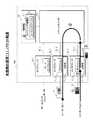
図20に示した構成の本発明に関わる移動端末対応ルータ100の外部リンクインタフェース(図1のインタフェース10_2,10_3参照)におけるパケット受信処理手順(1)の実施例が図21に示され、ホームリンクインタフェース(同図のインタフェース10_1参照)におけるパケット受信処理手順(1)の実施例が図22に示されている。
【0195】
このパケット受信処理手順(1)では、図26に示した一般的なインターネットネットワークにおける従来のルータ110,120,130を、図20に示した本発明のルータ100に置き換え、以下の動作を行うものとする。
リンクインタフェース10
図1に示したインタフェース10_1〜10_3と同様に、図20に示したインタフェース10_1は、移動端末300に関するホームリンクインタフェースであり、インタフェース10_2,10_3は、外部リンクインタフェースであるものとする。
【0196】
移動端末300宛のパケット転送処理:図3に示した本発明の動作原理(1)に基づくパケット転送処理
移動端末300からのホームエージェントへの位置登録処理手順:図29に示した従来の位置登録処理手順
外部リンクインタフェースにおけるキャッシュの情報取得処理手順:図10に示した本発明の動作原理(5)に基づくキャッシュの情報取得処理手順、なお、図20のカプセル化用キャッシュ12は、図2に示したバインディング情報を記憶するものとする。
外部リンクインタフェースにおけるパケット受信処理手順(1)
図21に基づき外部リンクインタフェースにおけるパケット受信処理手順(1)を以下に説明する。なお、この処理は図10では、例えば、処理部13_3が行う処理に相当する。
【0197】
図21のステップS101〜S104:パケット71がリンク側から入力された場合で、且つパケットの宛先アドレス=“10.10”に対応するバインディング情報がキャッシュ12に記憶されていない(キャッシュがない)場合、外部リンクインタフェース10は、受信パケット71をルータコア20(パケットスイッチ21)に入力すると共に、キャッシュ要求メッセージ73を生成してルータコア20へ入力する(図10の▲1▼〜▲3▼参照)。
【0198】
ステップS102,S105〜S107:リンク側から入力されたパケット71の宛先アドレスに対応するバインディング情報がキャッシュ12に記憶されている(キャッシュがある)場合で、且つパケットのカプセル化が有効な場合、パケット71をカプセル化して、このカプセル化パケット72をルータコア20に入力する(図3の▲1▼〜▲3▼参照)。なお、パケットのカプセル化の有効/無効の設定は、例えば、保守者によって決定される。ルータ100は、有効に設定された場合、パケットのカプセル化を行い、無効に設定された場合、パケットのカプセル化を行わない。
【0199】
ステップS105,S107:パケットのカプセル化が無効な場合、パケットをカプセル化せずにルータコア20に入力する。
ステップS101,S108,S109:ルータコア側から入力されたパケットがキャッシュ応答メッセージ74である場合、キャッシュを作成する。すなわち、応答メッセージ74に含まれるバインディング情報をキャッシュ12に記憶する(図10の▲8▼参照)。
【0200】
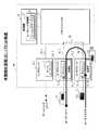
ステップS108,S110:ルータコア側から入力されたパケットがキャッシュ応答メッセージ74でない場合(パケットがカプセル化された移動端末宛のパケットである場合)、パケットをリンク側に送信する(図3の▲5▼又は図10の▲7▼’参照)。ホームリンクインタフェースにおけるパケット受信処理手順(1)
図22に基づき、ホームリンクインタフェースにおけるパケット受信処理手順(1)を以下に説明する。なお、この処理は、図1ではホームエージェント11又はインタフェース10_1に含まれる処理部(図示せず。)が行う処理に相当する。
【0201】
ステップS201〜S204:リンク側から入力されたパケットの宛先アドレスに対応するバインディング・キャッシュが有る場合(すなわち、宛先アドレスに対応するバインディング情報がバインディング・キャッシュ14(図1参照)に有る場合)、入力パケットをカプセル化して、ルータコア20側に出力する(図10の▲4▼',▲5▼,▲6▼参照)。
【0202】
この処理は、ホームリンク側から入力された移動端末宛のパケットをカプセル化してルーティングする処理に相当する。
ステップS202,S204:リンク側から入力されたパケットの宛先アドレスに対応するバインディング情報がバインディング・キャッシュ14に無い場合、カプセル化せずにパケットをルータコア20に入力する。この処理は、ホームリンク側から入力されたカプセル化する必要のない端末宛パケット又は端末からのバインディング要求パケットをルーティングする処理に相当する。
【0203】
ステップS201,S205〜S207:ルータコア20側から入力されたパケットが、バインディング要求パケット81である場合、バインディング・キャッシュ14を更新すると共にバインディング応答パケット82を生成し、生成したパケット82をルータコア20側に出力する(図29の▲3▼〜▲5▼参照)。この処理は、ホームエージェントにおける位置登録に相当する。
【0204】
ステップS205,S208〜S210:ルータコア20側から入力されたパケットが キャッシュ要求メッセージ73である場合、キャッシュ応答メッセージ74を生成し、生成した応答メッセージ74をルータコア側に出力する。また、要求メッセージ送信元を記憶する(図10の▲4▼',▲5▼,▲6▼参照)。
【0205】
>ステップS208,S211:ルータコア20側から入力されたパケットがバインディング要求パケット及びキャッシュ要求メッセージで無い場合、パケットをリンク側に送信する。この処理は、ホームリンクにルーティングされたパケットをホームリンクに出力する処理である。
【0206】
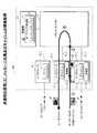
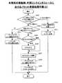
図23は、本発明の移動端末対応ルータ100における外部リンクインタフェース別の実施例であるパケット受信処理手順(2)を示しており、図24は、本発明の移動端末対応ルータ100のホームリンクインタフェースにおける別の実施例であるパケット受信処理手順(2)を示している。これらの受信処理手順(2)は、以下の実施形態を前提としている。
【0207】
移動端末300宛パケットの転送処理手順:図4に示した本発明の動作原理(2)に基づくパケット転送処理手順
移動端末300からのホームエージェントへの位置登録処理手順:図8に示した本発明の動作原理(4)に基づく位置登録処理手順
外部リンクインタフェースにおけるキャッシュの情報取得処理手順:図18及び図19にそれぞれ示した本発明の動作原理(11)及び(12)に基づくキャッシュの情報取得処理手順、なお、この手順ではキャッシュには図5及び図9に示したバインディング情報が記憶されるものとする。
【0208】
外部リンクインタフェースにおけるパケット受信処理手順(2)
図23に基づき、外部リンクインタフェースにおけるパケット受信処理手順(2)を以下に説明する。
ステップS301〜S304:リンク側から入力されたパケットの宛先アドレスに対応するキャッシュが無い場合、パケットに自身のインタフェース識別子を付与してルータコア側に出力する(図18の▲1▼〜▲3▼、又は図19の▲1▼〜▲3▼参照)。
【0209】
ステップS302,S305〜S309:リンク側から入力されたパケットの宛先アドレスに対応するバインディング情報がキャッシュ12にある(キャッシュが有る)場合で、且つカプセル化が有効な場合、パケットをカプセル化し、キャッシュ(図5又は図9参照)から出力インタフェースを検出し、カプセル化パケットに識別子を付与した後、このパケットを制御ルート32経由で出力インタフェースに出力する(図4の▲1▼〜▲3▼参照)。
【0210】
ステップS305,S307〜S309:カプセル化が無効な場合、キャッシュ(図5又は図9参照)から出力インタフェースを検出し、識別子を付与した後、このパケットをカプセル化せずに制御ルート32経由で出力インタフェースに出力する。
ステップS301,S310,S311:ルータコア20側から受信したパケットからインタフェース識別子を削除して、リンク側に送信する。(図18及び19の▲7▼'参照)。
【0211】
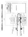
ホームリンクインタフェースにおけるパケット受信処理手順(2)
図24に基づき、ホームリンクインタフェースにおけるパケット受信処理手順(2)を以下に説明する。
ステップS401〜S404:リンク側から受信したパケットの宛先アドレスに対応するバインディング情報がバインディング・キャッシュ14に無い場合、パケットにインタフェース識別子を付与してルータコア20側に出力する。
【0212】
ステップS401,S402,S405〜S408:リンク側から受信したパケットの宛先アドレスに対応するバインディング・キャッシュ14(図5参照)が有る場合、パケットをカプセル化し、キャッシュ14から出力インタフェースを検索し、検索したインタフェースの識別子をパケットに付与した後、出力インタフェースに出力する。
【0213】
ステップS401,S409〜S415:ルータコア20側から受信したバインディング要求パケット81のインタフェースの識別子が変わった場合、旧インタフェースのキャッシュを削除した後、インタフェース識別子の更新を行う。そして、バインディング・キャッシュ14の更新及びバインディング応答パケット82の生成を行い、生成したバインディング応答パケット82に出力インタフェースの識別子付与した後、ルータコア側に出力する(図19の▲4▼',▲5▼,▲6▼,▲7▼'参照)。
【0214】
ステップS410,S413〜S415:ルータコア20側から受信したバインディング要求パケット81のインタフェース識別子が変わらなかった場合、バインディング・キャッシュ14の更新及びバインディング応答パケット82の生成を行い、生成したバインディング応答パケット82に出力インタフェースの識別子付与した後、ルータコア側に出力する(図19の▲4▼',▲5▼,▲6▼,▲7▼'参照)。
【0215】
ステップS401,S409,S416〜S421:ルータコア20側から受信したパケットがバインディング要求パケット81でない場合で、且つこのパケットの宛先アドレスがバインディング・キャッシュ14に有る場合、入力元インタフェースのキャッシュを設定して入力元インタフェースを記憶する。そして、パケットをカプセル化すると共にインタフェース識別子を付与した後、ルータコア側に出力する(図18の▲4▼',▲5▼,▲6▼参照)。
【0216】
ステップS416,S422:ルータコア20側から受信したパケットがバインディング要求パケットでない場合で、このパケットの宛先アドレスがバインディング・キャッシュ14に無い場合、パケットをリンク側に送信する。
ルータコア20におけるパケット処理手順
図25は、図20に示した本発明の移動端末対応ルータ100のルータコア20におけるパケット処理手順の実施例を示している。この処理は、「パケット転送ルート」に関する処理であり、ルータコア20はパケット処理手順を繰り返し実行する。
【0217】
ステップS501:パケットバッファ54にパケットが記憶されていない場合、パケットをスイッチング(ルーティング)処理等を行う必要はないのでループを終了した後、ステップS501に戻りループを繰り返す。
ステップS501〜S503:パケットバッファ54にパケットが記憶されている場合で、且つパケットの宛先アドレスがルータ自身である場合、自分宛のパケット処理(プロトコル処理等)を実行する。
【0218】
ステップS501,S502,S504,S505,S507:パケットバッファ54にパケットが記憶されている場合で、且つパケットの宛先アドレスがルータ自身でない場合で、且つルーティングテーブル24を検索して出力インタフェースが決定できる場合、決定した出力インタフェースにパケットを出力する。
【0219】
ステップS505〜S507:ルーティングテーブル24を検索して出力インタフェースが決定できない場合、受信したパケットを廃棄すると共に、エラーメッセージパケットを作成し、作成したパケット送信元に対応する出力インタフェースに出力する。
【0220】
(付記1)
移動可能な端末のホームリンクに接続されたホームリンクインタフェースと、該端末の外部リンクに接続された外部リンクインタフェースとを備え、
該外部リンクインタフェースが、該端末のバインディング情報を記憶したカプセル化用キャッシュと、該端末宛のパケットを該バインディング情報に含まれるケア・オブ・アドレスでカプセル化する処理部と、を有することを特徴とした移動端末対応ルータ。
【0221】
(付記2)上記の付記1において、
該バインディング情報が、該端末のホームアドレス及び移動時のケア・オブ・アドレスを関連付けた情報であることを特徴とした移動端末対応ルータ。
(付記3)上記の付記2において、
該バインディング情報が、該カプセル化したパケットを出力する出力インタフェースを該ケア・オブ・アドレスと関連付けていることを特徴とした移動端末対応ルータ。
【0222】
(付記4)上記の付記1において、
該バインディング情報が、自分の有効時間を含むことを特徴としたした移動端末対応ルータ。
(付記5)上記の付記1において、
該処理部が、該カプセル化したパケットをパケット転送ルート経由で出力インタフェースに送出することを特徴とした移動端末対応ルータ。
【0223】
(付記6)上記の付記3において、
該処理部が、該カプセル化したパケットを該出力インタフェースに与えることを特徴とした移動端末対応ルータ。
(付記7)上記の付記1において、
該処理部が、該端末からのバインディング要求パケットを受信したとき、該バインディング要求パケットに含まれる該バインディング情報を該カプセル化用キャッシュに記憶することを特徴とした移動端末対応ルータ。
【0224】
(付記8)上記の付記7において、
該処理部は、該バインディング要求パケットに対するバインディング応答パケットをパケット転送ルート経由で出力インタフェースに与えることを特徴とした移動端末対応ルータ。
【0225】
(付記9)上記の付記7において、
該カプセル化用キャッシュが、該バインディング応答パケットを出力する出力インタフェースを該バインディング情報の内の該端末のケア・オブ・アドレスと関連付けて記憶しており、
該処理部が、該バインディング情報に基づき、該バインディング応答パケットを該出力インタフェースに与えることを特徴とした移動端末対応ルータ。
【0226】
(付記10)上記の付記1において、
該処理部は、該端末に係るパケットを受信したとき、該カプセル化用キャッシュが該端末のバインディング情報を記憶していない場合、ホームエージェントから該バインディング情報を取得することを特徴とした移動端末対応ルータ。
【0227】
(付記11)上記の付記10において、
該端末に係るパケットが、該端末宛のパケットであることを特徴とした移動端末対応ルータ。
(付記12)上記の付記10において、
該端末に係るパケットが、該端末からのバインディング要求パケットであることを特徴とした移動端末対応ルータ。
【0228】
(付記13)上記の付記10において、
該処理部は、該バインディング情報を記憶していないことを要求メッセージで該ホームエージェントに通知することを特徴とした移動端末対応ルータ。
(付記14)上記の付記10において、
該処理部は、自分が属する外部リンクインタフェースの識別子を該パケットに付与することにより、パケット転送ルートで、該バインディング情報が記憶されていないことを該ホームエージェントに通知することを特徴とした移動端末対応ルータ(5)。
【0229】
(付記15)上記の付記10において、
該処理部は、装置内制御ルートを経由して該ホームエージェントから該バインディング情報を獲得することを特徴とした移動端末対応ルータ。
(付記16)上記の付記10において、
該処理部は、装置内制御ルートを経由してルーティングテーブルから必要な情報を獲得することを特徴とした移動端末対応ルータ。
【0230】
(付記17)上記の付記10において、
該ホームエージェントは、該カプセル化用キャッシュが該バインディング情報を記憶していないことを示す通知を受信したとき、自分が保持するバインディング・キャッシュから必要な情報を該処理部に通知することを特徴とした移動端末対応ルータ。
【0231】
(付記18)上記の付記17において、
該ホームエージェントは、応答メッセージで該バインディング情報をパケット転送ルートを経由して通知することを特徴とした移動端末対応ルータ。
(付記19)上記の付記17において、
該ホームエージェントが、該バインディング情報を装置内制御ルートを経由して通知することを特徴とした移動端末対応ルータ。
【0232】
(付記20)上記の付記10において、
該ホームエージェントは、該通知が出力インタフェースの識別子で行われたとき、自分が属する出力インタフェースの識別子を付与した該バインディング情報を通知することを特徴とした移動端末対応ルータ。
【0233】
(付記21)上記の付記17において、
該ホームエージェントは、該通知を送信した外部リンクインタフェースを記憶しておき、この後、該端末からのバインディング要求パケットを受信したとき、該バインディング要求パケットに含まれるバインディング情報を該記憶した外部リンクインタフェースに送信することを特徴とした移動端末対応ルータ。
【0234】
(付記22)
移動可能な端末のホームリンクに接続されたホームリンクインタフェースと、該端末の外部リンクに接続された外部リンクインタフェースとを備え、
該外部リンクインタフェースが、該端末のホームエージェントの代わりにモバイルIPメッセージの交換を行う処理部と、該モバイルIPメッセージに含まれる該端末のバインディング情報を記憶したキャッシュと、を有することを特徴とした移動端末対応ルータ。
【0235】
(付記23)上記の付記22において、
該モバイルIPメッセージが、該端末から受信したバインディング要求パケット及びこれに応答するバインディング応答パケットであることを特徴とした移動端末対応ルータ。
【0236】
(付記24)上記の付記22において、
該処理部は、該ホームエージェントのバインディング・キャッシュが記憶するバインディング情報を更新するために必要な情報を該モバイルIPメッセージで受信したとき、該必要な情報を該ホームエージェントに送信すること特徴とした移動端末対応ルータ。
【0237】
(付記25)上記の付記1又は付記22において、
該ホームエージェントが、少なくとも該ホームリンク上に在るか又は該ホームリンクインタフェースに含まれるかのいずれかであることを特徴とした移動端末対応ルータ。
【0238】
【発明の効果】
以上説明したように、本発明に係る移動端末対応ルータによれば、該移動端末宛パケットのカプセル化処理がホームエージェントを経由せずに行われることになりカプセル化処理時間を短縮することが可能になる。
【0239】
また、該処理部が、移動端末からのバインディング要求パケットを受信し、バインディング要求パケットに含まれるバインディング情報をカプセル化用キャッシュに記憶することにより、該カプセル化用キャッシュの更新を可能にする。
さらに、該処理部が該バインディング要求パケットに対するバインディング応答パケットをパケット転送ルート経由で出力インタフェースに与えるように構成したので、モバイルIPメッセージ処理を短縮することが可能になる。
【0240】
また、該処理部が、カプセル化した該移動端末宛パケット又は該バインディング応答パケットをパケット転送ルートとは別の装置内制御ルート経由で該出力インタフェースに与えるように構成したので、パケットをパケット転送ルートを経由することなく出力インタフェース10_2に直接与えられ、パケット転送の高速化が可能になる。
【0241】
また、該処理部が移動端末に係るパケット、例えば移動端末宛パケット又は移動端末からのバインディング要求パケットを受信したとき、該カプセル化用キャッシュが受信した端末のバインディング情報を記憶していない場合、パケット転送ルート又は装置内制御ルートを経由してホームエージェントから該バインディング情報を取得するように構成したので、該キャッシュは移動端末に関するバインディング情報を取得・記憶することが可能になる。
【0242】
さらに、外部リンクインタフェースの処理部が、移動端末のホームエージェントの代わりにモバイルIPメッセージの交換を行い、このメッセージの内の必要な情報のみをホームエージェントに通知し、キャッシュが該メッセージに含まれる該移動端末のバインディング情報を記憶するように構成したので、ルータ内のメッセージ伝送負荷が軽くなる。
【0243】
上記のように外部リンクインタフェースのキャッシュは、移動端末宛パケットをカプセル化するための情報、さらにルータが生成するルーティングテーブルの情報、又は移動中の端末から送信されたバインディング要求パケットに基づいて生成されるバインディング情報等を一時的に記憶するものである。
【0244】
また、このキャッシュの情報に基づき外部リンクインタフェースの処理部は、ホームエージェントと同様のカプセル化処理、ルーティング処理(出力インタフェースの決定)、又はモバイルIPメッセージ交換処理を行うものである。
これらのキャッシュ及び処理部を備えた本発明に係るルータによれば、ルータ内におけるカプセル化処理、パケットルーティング及び転送処理、モバイルIPメッセージ処理等の処理ルートを短縮することにより、処理時間が短縮されると共に、使われなくなったルートを他のパケット転送用に使用することが可能になり、端末の通信品質劣化の原因となるパケット遅延やパケット廃棄を防ぐことが可能になる。
【図面の簡単な説明】
【図1】本発明に係る移動端末対応ルータの実施例を示したブロック図である。
【図2】本発明に係る移動端末対応ルータにおけるカプセル化用キャッシュの内容例(1)を示した図である。
【図3】本発明に係る移動端末対応ルータの動作原理(1):パケット転送動作例を示した図である。
【図4】本発明に係る移動端末対応ルータの動作原理(2):パケット転送動作例を示した図である。
【図5】本発明に係る移動端末対応ルータにおけるカプセル化用キャッシュの内容例(2)を示した図である。
【図6】本発明に係る移動端末対応ルータの動作原理(3):モバイルIPメッセージ交換及びキャッシュの情報取得手順例を示した図である。
【図7】本発明に係る移動端末対応ルータにおけるカプセル化用キャッシュの内容例(3)を示した図である。
【図8】本発明に係る移動端末対応ルータの動作原理(4):モバイルIPメッセージ交換及びキャッシュの情報取得手順例を示した図である。
【図9】本発明に係る移動端末対応ルータにおけるカプセル化用キャッシュの内容例(4)を示した図である。
【図10】本発明に係る移動端末対応ルータの動作原理(5):カプセル化用キャッシュの情報取得手順例を示した図である。
【図11】本発明に係る移動端末対応ルータにおけるリンクインタフェース間で交換されるメッセージの構成例(1)を示した図である。
【図12】本発明に係る移動端末対応ルータの動作原理(6):カプセル化用キャッシュの情報取得手順例を示した図である。
【図13】本発明に係る移動端末対応ルータにおけるリンクインタフェース間で交換されるメッセージの構成例(2)を示した図である。
【図14】本発明に係る移動端末対応ルータの動作原理(7):カプセル化用キャッシュの情報取得手順例を示した図である。
【図15】本発明に係る移動端末対応ルータの動作原理(8):カプセル化用キャッシュの情報取得手順例を示した図である。
【図16】本発明に係る移動端末対応ルータの動作原理(9):カプセル化用キャッシュの情報取得手順例を示した図である。
【図17】本発明に係る移動端末対応ルータの動作原理(10):カプセル化用キャッシュの情報取得手順例を示した図である。
【図18】本発明に係る移動端末対応ルータの動作原理(11):カプセル化用キャッシュの情報取得手順例を示した図である。
【図19】本発明に係る移動端末対応ルータの動作原理(12):カプセル化用キャッシュの情報取得手順例を示した図である。
【図20】本発明に係る移動端末対応ルータの実施例:構成を示したブロック図である。
【図21】本発明に係る移動端末対応ルータの外部リンクインタフェースにおけるパケット受信処理手順例(1)を示したフローチャート図である。
【図22】本発明に係る移動端末対応ルータのホームリンクインタフェースにおけるパケット受信処理手順例(1)を示したフローチャート図である。
【図23】本発明に係る移動端末対応ルータの外部リンクインタフェースにおけるパケット受信処理手順例(2)を示したフローチャート図である。
【図24】本発明に係る移動端末対応ルータのホームリンクインタフェースにおけパケット受信処理手順例(2)を示したフローチャート図である。
【図25】本発明に係る移動端末対応ルータのルータコアにおけるパケット処理手順例を示したフローチャート図である。
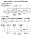
【図26】一般的なモバイルIPv6移動端末対応ルータで構成されたネットワークにおける移動端末による位置登録の動作手順を示した図である。
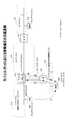
【図27】一般的なモバイルIPv6移動端末対応ルータで構成されたネットワークにおける移動端末宛パケットの転送動作手順を示した図である。
【図28】従来の移動端末対応ルータの構成を示したブロック図である。
【図29】従来の移動端末対応ルータ内における位置登録の動作手順を示した図である。
【図30】従来の移動端末対応ルータ内における位置登録で交換されるバインディングパケット及びバインディング情報を示した図である。
【図31】一般な移動端末対応ルータにおいて用いられるルーティングテーブル例を示した図である。
【図32】従来の移動端末対応ルータ内におけるパケット転送手順を示した図である。
【図33】一般な移動端末対応ルータにおいて転送される移動端末宛パケットの構成例を示した図である。
【符号の説明】
100,110,120,130 ルータ 210,220,230,240,250 リンク
300 移動端末 310 端末(固定又は移動)
10_1 ホームリンクインタフェース
10_2〜10_3 外部リンクインタフェース
11 ホームエージェント 12,12_2,12_3 カプセル化用キャッシュ
13,13_2,13_3 処理部 14 バインディング・キャッシュ
20 ルータコア 21 パケットスイッチ
22 制御部 23 ルーティング処理部
24 ルーティングテーブル
30,30_1〜30_3 パケット転送用バス(パケット転送ルート)
31 制御用バス
51 プロセッサ 52 メモリ
53 スイッチインタフェース 54 パケットバッファ
55 制御インタフェース 61 プロセッサ
62 メモリ 63 制御インタフェース
64 受信インタフェース 65 受信バッファ
66 制御部 67 スイッチインタフェース
68 送信バッファ 69 送信インタフェース
71 パケット 72 カプセル化パケット
73 要求メッセージ 74 応答メッセージ
75〜78 識別子 81 バインディング要求パケット
81a IPヘッダ
81b バインディング・アップデート・オプション
81c ホームアドレス・オプション
81d 認証ヘッダ 82 バインディング応答パケット
82a IPヘッダ 82b ルーティングヘッダ
82c バインディング・アクノリッジメント・オプション
82d 認証ヘッダ 83 要求メッセージ
84 応答メッセージ 85〜88 識別子[0001]
BACKGROUND OF THE INVENTION
The present invention relates to a mobile terminal compatible router, and relates to a mobile terminal compatible router connected to a network in which mobile IPv4 / v6 operates.
In the IP network, Mobile IPv4 has been standardized in the RFC2002 as a protocol that allows terminals to communicate even if the connection position on the network changes, in the US standardization organization IETF (Internet Engineering Task Force). Yes.
[0002]
In recent years, the problem of IP address exhaustion has become serious due to the rapid increase in the number of terminals existing on the IP network. In order to solve this problem, IPv6, which can use more IP addresses, has been standardized in the document RFC2460, and a shift to a network using these IP addresses is in full swing.
[0003]
For this reason, it is important to standardize mobile IPv6 as a protocol that supports not only mobile IP in a normal IPv4 network but also movement of terminals on an IPv6 network. In the IETF Mobile IP Working Group, A draft for standardization (see Draft Standard: document draft-ietf-mobileip-ipv6-13.txt) has been prepared.
[0004]
[Prior art]
The packet forwarding in Mobile IPv6 based on the above standard draft is described below. Since the contents of standardization for mobile IPv4 and mobile IPv6 are the same, description of mobile IPv4 is omitted.
[0005]
FIG. 26 shows a general Internet network. In this network, the
[0006]
The IP addresses (subnet prefix) of the
[0007]
In mobile IPv6, for example, the
[0008]
A home agent that supports movement of the
[0009]
The
(1)Mobile terminal location registration
When the
[0010]
The home agent that has received the binding update generates a
Hereinafter, the operation procedure of location registration of the mobile terminal in IPv6 will be described more specifically.
[0011]
(1) The terminal 300 (home address = 10.10) moves from the
(2) The
[0012]
(3) The
(4) The
[0013]
The
(5) Further, the
[0014]
The binding acknowledgment corresponds to a registration reply message in mobile IPv4.
Thereafter, the
[0015]
The
(2)Forwarding packets addressed to mobile terminals
FIG. 27 shows an example of packet transfer in mobile IPv6. This example shows an operation in which the
[0016]
(1) The
(2) The home agent (router 110) 11 receives the
[0017]
Since the
(3) The
[0018]
As described above, in the mobile IPv6, when the packet is transmitted to the terminal moving to the external link, the
[0019]
Further, when the number of terminals supported by the
In order to deal with these problems, in mobile IPv6, for example, when the terminal 300 moving to the
[0020]
If this route optimization function operates, the
[0021]
Further, even if a binding update is transmitted from the terminal 300 to the
[0022]
In these cases, the
In Mobile IPv4, the route optimization function itself is not completely defined, and is being studied in the above document (draft-ietf-mobileip-optim-10.txt).
[0023]
(3)Router configuration
FIG. 28 shows a configuration example of a
[0024]
The interface 10_1 has the
[0025]
The
[0026]
The basic operation of each functional block will be described below.
Link interfaceTenHas a line interface (not shown) for connecting to other routers or network devices, receives packets transmitted from other routers or network devices and inputs them to the
[0027]
The
Home agent11Is a mobile IPv6 (or mobile IPv4) compatible home agent, and when the terminal 300 on the supported home link 210 (see FIG. 26) moves to an external link, the terminal 300 and the mobile IPv6 message (binding request packet) , Binding response packet, etc.), generating and holding the binding
[0028]
It is conceivable that the
[0029]
Packet switchtwenty onePerforms a process of distributing a packet input from the
Control unittwenty twoPerforms overall control of the
[0030]
Routing processortwenty threeIn particular, the routing table 24 is created according to the setting by the maintenance person or the routing protocol, and the routing process for determining the
[0031]
(Four)Location registration operation in the router
FIG. 29 shows the internal operation of the
[0032]
In FIG. 26, the terminal 300 moving to the
FIG. 30 (1) shows a binding request packet (hereinafter sometimes abbreviated as a BU packet) 81. The
[0033]
The IP header 81a is composed of a destination address (the address “10.1” of the home agent 11) and a transmission source address (care of address of the terminal 300 = “20.10”), and the option 81b is composed of a sequence number and an effective time. The option 81c is composed of the home address “10.10” of the terminal 300, and the authentication header 81d is composed of authentication data and the like.
[0034]
(1) In the
{Circle around (2)} The
[0035]
FIG. 31 shows an example of the routing table 24. The table 24 includes a destination prefix, a next hop router, the number of hops, and an output interface.
The
[0036]
(3) The
(4) In the interface 10_1, the
[0037]
The
[0038]
FIG. 30 (2) shows a configuration example of the binding
[0039]
(5) The
FIG. 30 (3) shows a configuration example of the
[0040]
The IP header 82a is configured with the care-of address = “20.10” of the terminal 300 that is the destination address 82_1 and the home agent address = “10.1” that is the source address 82_2, and the home address of the terminal 300 is included in the routing header 82b. 82_3 = “10.10” is inserted, the
[0041]
(6) The
(7) The
[0042]
(Five)Packet forwarding operation in the router
FIG. 32 shows an example of packet transfer processing inside the
The
[0043]
FIG. 33 (1) shows the configuration of the
[0044]
(1) In the
(2) The
[0045]
(3) The
(4) In the interface 10_1, the
[0046]
(5) The
FIG. 33 (2) shows the configuration of the encapsulated
[0047]
{Circle around (6)} The
(7) The
[0048]
[Problems to be solved by the invention]
As shown in FIGS. 29 and 32, in the
[0049]
For this reason, when
[0050]
In the
[0051]
When the packet addressed to the moving
[0052]
Therefore, the present invention reduces the processing time of packet encapsulation processing for the mobile terminal and mobile IP message processing related to the mobile terminal in a mobile terminal compatible router connected to a network operating mobile IPv4 / v6. It is an object of the present invention to prevent packet delay and packet discarding that cause terminal communication quality degradation.
[0053]
[Means for Solving the Problems]
In order to solve the above problems, a mobile terminal compatible router of the present invention includes a home link interface connected to a home link of a mobile terminal and an external link interface connected to an external link of the terminal, The external link interface encapsulates the encapsulation cache storing the binding information of the terminal and the packet addressed to the terminal with the care-of address included in the binding information.At the same time, the encapsulated packet is sent to the output interface via the packet transfer route, but not via the routing processing unit.And a processing unit (claim 1).
[0054]
FIG. 1 shows a configuration example of a mobile terminal
[0055]
Similarly, the external link interface 10_2 connected to the external link 250 includes an encapsulation cache 12_2 (hereinafter, the caches 12_2 and 12_3 may be collectively referred to as the cache 12) and the
The
[0056]
Note that the in-
[0057]
For example, as shown in FIG. 2, the cache 12_3 stores the home address = “10.10” and the care-of address (CoA) = “20.10” of the
[0058]
Hereinafter, the operation when the
For example, the
[0059]
Thereby, the encapsulation processing of the
FIG. 3 shows an operation principle (1) of the
[0060]
(1) The
(2) In the link interface 10_3, the processing unit 13_3 searches for information in the cache 12_3 based on the destination address (home address of the mobile terminal 300) = “10.10” of the received packet 71 (see FIG. 33 (1)). (See FIG. 2). When the cache 12_3 stores binding information in which the home address of the
[0061]
(3) The processing unit 13_3 inputs the
(4) The
[0062]
(5) The
As shown in the above operations (3) to (5), the
[0063]
Also, in the present invention, in the above invention, the binding information can include its valid time. As a result, when the
[0064]
In the present invention, the above binding information can further associate an output interface that outputs the encapsulated packet with the care-of address (Appendix 3), and the processing is performed based on the binding information. Can provide the encapsulated packet to the output interface (Appendix 6).
[0065]
FIG. 4 shows an operation principle (2) of the
[0066]
Further, unlike the
Based on FIG. 4, the operation procedure in which the
[0067]
(1) The
(2) In the interface 10_3, the processing unit 13_3 searches the cache 12_3, and the care-of address of the terminal 300 corresponding to the destination address (home address of the terminal 300) = “10.10” of the received
[0068]
(3) Further, the
(4) The interface 10_2 transmits the
[0069]
Thereby, the
In the present invention, in the above invention, when the processing unit receives a binding request packet from the terminal, the binding information included in the binding request packet can be stored in the encapsulation cache. (Claim 2).
[0070]
That is, FIG. 6 shows an operation principle (3) of the
[0071]
FIG. 7 shows the contents stored in the cache 12_2, which is the same as the binding information of the
In FIG. 6, the processing unit 13_2 can receive the binding request packet (BU packet) 81 from the
[0072]
Furthermore, in the present invention, the processing unit 13_2 can give the
That is, in the figure, the processing unit 13_2 creates a
[0073]
A mobile IP message processing example of the
(1) The binding request packet 81 (see FIG. 30 (1)) transmitted by the
[0074]
(2) In the interface 10_2, the processing unit 13_2 analyzes the type of the received
[0075]
When the binding information of the
[0076]
(3) The processing unit 13_2 outputs the
(4) The
[0077]
(5) The
As described above, the processing unit 13_2 performs the mobile IP message processing instead of the
[0078]
In the present invention, in the above invention, the encapsulation cache stores an output interface that outputs the binding response packet in association with the care-of address of the terminal in the binding information. The processing unit can give the binding response packet to the output interface based on the information in the encapsulation cache (Appendix 9).
[0079]
FIG. 8 shows an operation principle (4) of the
[0080]
Further, the processing unit 13_2 is different from the cache 12_2 in that the
Hereinafter, the operation of the
[0081]
(1) The binding request packet 81 (see FIG. 30 (1)) transmitted by the terminal 300 moving to the
(2) In the interface 10_2, the processing unit 13_2 analyzes the type of the received
[0082]
When the cache 12_2 stores the binding information of the home address = “10.10”, the processing unit 13_2 updates the cache 12_2 based on the contents of the
[0083]
(3) The processing unit 13_2 refers to the cache 12_2, searches for the interface 10_2 that is an output interface of the
[0084]
(4) The interface 10_2 transmits the
Thus, the
In the operation principle (1) and (2) of the present invention described above with reference to FIGS. 3 and 4, the procedure of the transfer process of the packet addressed to the mobile terminal will be described, respectively, and will be described with reference to FIGS. In the operation principle (3) and (4) of the present invention, the mobile IP message exchange process and the acquisition of binding information of the encapsulation cache have been described.
[0085]
In the operation principle (5) to (12) of the present invention described below in FIGS. 10, 12, and 14 to 19, respectively, the external link interface is connected from the packet addressed to the mobile terminal or the mobile terminal. When the encapsulating cache does not store the binding information of the mobile terminal when the packet is received from the home agent, the binding information (cache information and cache information shown in FIG. 2, FIG. 5, FIG. 7 and FIG. 9) is received from the home agent. The procedure for acquiring the information will be described.
[0086]
The basic configuration of the mobile terminal
Further, in the mobile terminal
[0087]
The packet related to the terminal includes a packet addressed to the terminal and a binding request packet from the terminal (
That is, in FIG. 1, when the processing unit 13_3 of the external link interface 10_3 for the
[0088]
In such a case, the processing unit 13_3 can acquire the binding information regarding the terminal 300 from the home agent and write it in the cache 12_3.
As a result, the cache 12_3 can acquire and store the binding information related to the terminal 300, and the processing unit can encapsulate the packet when the packet related to the terminal is received.
[0089]
In the present invention, in the above invention, the processing unit can notify the home agent by a request message that the binding information is not stored (claim 4).
FIG. 10 shows an operation principle (5) of the mobile terminal
[0090]
Here, it is assumed that the cache 12_3 does not store any binding information.
(1) The packet 71 (see FIG. 33 (1)) transmitted by the terminal 310 arrives at the
[0091]
(2) In the interface 10_3, the processing unit 13_3 searches for information in the cache 12_3 based on the destination address of the received packet 71 (the home address of the terminal 300 = 10.10). When the cache 12_3 does not store the binding information (care of address) regarding the destination address, the processing unit 13_3 generates a
[0092]
FIG. 11 (1) shows a configuration example of the
[0093]
(3) The processing unit 13_3 inputs the received
After (4) and (4) ', the
[0094]
That is, (4) the
[0095]
With the request message, the processing unit 13_3 of the interface 10_3 can notify the
Next, the procedure in which the
[0096]
That is, in the present invention, in the above invention, when the
[0097]
{Circle around (5)} The
[0098]
Further, the
[0099]
FIG. 11 (2) shows a configuration example of the
[0100]
Note that the messages shown in FIGS. 11 (1) and 11 (2) are exchanged uniquely within the
Here, the
[0101]
The
(6) The
[0102]
(7), (7) ', (7) "The
That is, (7) the
[0103]
Further, the
{Circle around (7)} The
[0104]
{Circle over (7)} The
(8) In the interface 10_3, the processing unit 13_3 analyzes the type of the input response message (packet) 74 and detects that the
[0105]
In this way, the
The cache contents shown in FIG. 2 are generated in the interface 10_3 by the information acquisition process of the cache 12_3. Thereafter, the processing unit 13_3 can transfer the
[0106]
FIG. 12 shows an operation principle (6) of the
[0107]
Here, it is assumed that the cache 12_2 does not store any binding information.
Hereinafter, an example of acquiring cache information based on the operation principle (6) will be described more specifically.
[0108]
(1) The binding request packet 81 (see FIG. 30 (1)) transmitted by the terminal 300 is transmitted to the
(2) In the interface 10_2, the processing unit 13_2 analyzes the type of the received
[0109]
When the binding information of the terminal 300 is not stored in the cache 12_2, the processing unit 13_2 generates a
FIG. 13 (1) shows a configuration example of the
[0110]
As described above, in the present invention, the processing unit can request the binding information to the
(3) The processing unit 13_3 inputs the received
[0111]
After (4), (4) ', the
[0112]
(5) In the interface 10_1, the
[0113]
Then, the
Similarly, the
[0114]
FIG. 13 (2) shows the configuration of the
[0115]
Note that the messages shown in FIGS. 13 (1) and (2) are exchanged independently in the router, and therefore, using new new options 83b and 84b that are not defined in the IP standard, respectively. Yes.
In addition, the
[0116]
(6) The interface 10_1 inputs the
(7), (7) ', (7) "Both the
[0117]
(8) In the interface 10_2, the processing unit 13_2 detects the display 84_3 included in the input response message (packet) 84, and recognizes that the
[0118]
Through the above processing, binding information related to the
[0119]
FIG. 14 shows an operation principle (7) of the
[0120]
Here, it is assumed that the cache 12_3 is in a state where no binding information is stored.
(1) The
[0121]
(2) In the interface 10_3, the processing unit 13_3 searches the binding information of the cache 12_3 based on the destination address of the received
{Circle around (3)} The processor 13_3 inputs the received
[0122]
(4), (4) 'The
(5) In the interface 10_1, the
[0123]
(6) The
(7), (7) 'The
(8) In the interface 10_3, the processing unit 13_3 uses the in-device control route 32 because the cache did not store the binding information (care of address) for the destination address of the
[0124]
First, the processing unit 13_3 refers to the routing table 24 (see FIG. 31) via the
Thus, in the present invention, the processing unit can acquire necessary information (here, output interface information) from the routing table via the
[0125]
Next, the processing unit 13_3 confirms whether or not the
[0126]
Further, the processing unit 13_3 refers to the routing table 24 again based on the acquired care-of address, and also acquires the information of the output interface (here, the interface 10_2) for the care-of address = “20.10”. (Refer to 24b in the figure) and store in the cache 12_3.
[0127]
Note that the
Through the above processing, the binding information as shown in FIG. 5 is generated in the cache 12_3 of the interface 10_3. Thereafter, while the binding information is stored, the processing unit 13_3 can process the
[0128]
FIG. 15 shows an operation principle (8) of the
[0129]
Here, it is assumed that the cache 12_2 does not store any binding information.
(1) A binding request packet 81 (see FIG. 30 (1)) transmitted by the terminal 300 is transmitted to the
[0130]
(2) In the interface 10_2, the processing unit 13_2 analyzes the type of the
[0131]
(3) The processing unit 13_2 inputs the received
(4), (4) 'The
[0132]
(5) In the interface 10_1, the
[0133]
(6) The
(7), (7) 'The
(8) In the interface 10_2, the processing unit 13_2 does not store the binding information (care of address) for the terminal 300 that is the transmission source of the
[0134]
That is, the processing unit 13_2 refers to the routing table 24 (see FIG. 31) and knows that the output interface for the address “10.1” of the
Next, the processing unit 13_2 confirms with the
[0135]
Note that the
[0136]
Through the above processing, binding information related to the
[0137]
FIG. 16 shows an operation principle (9) of the
[0138]
When the
Here, it is assumed that the cache 12_3 is in a state where no binding information related to the terminal 300 is stored.
[0139]
(1) The packet 71 (see FIG. 33 (1)) transmitted by the terminal 310 is transmitted to the
(2) In the interface 10_3, the processing unit 13_3 searches the binding information of the cache 12_3 based on the destination address of the received
[0140]
(3) The processing unit 13_3 inputs the
(4), (4) 'The
(5) In the interface 10_1, the
[0141]
Then, since the binding information (FIG. 30 (2)) about the terminal 300 exists, the
[0142]
Note that the reason why the
[0143]
Instead of providing such an identifier, the
[0144]
Further, the
Note that the interface 10_1 stores the identifier of the input interface (in this case, the interface 10_3) of the
[0145]
(6) The
(7), (7) 'The
[0146]
(8) Based on the identifier assigned to the
(9) In the interface 10_3, the processing unit 13_3 analyzes the type of the input packet and detects that the
[0147]
Through the above processing, the binding information as shown in FIG. 2 is generated in the cache 12_3. Thereafter, while this binding information is stored, the processing unit 13_3 can perform the transfer process of the principle (1) shown in FIG. 3 for the
[0148]
FIG. 17 shows an operation principle (9) of the
[0149]
Here, it is assumed that the cache 13_2 does not store any binding information of the terminal 300.
(1) The binding request packet 81 (see FIG. 30 (1)) sent from the terminal 300 is sent to the
[0150]
(2) In the interface 10_2, the processing unit 13_2 analyzes the type of the received
[0151]
When the cache 12_2 does not store the binding information (care of address) regarding the terminal 300, the processing unit 13_2 does not process the
[0152]
(3) The processing unit 13_2 inputs the
(4), (4) 'The
(5) In the interface 10_1, the
[0153]
Then, as a response to the
[0154]
Here, the
[0155]
(6) The
(7), (7) 'The
[0156]
{Circle around (8)} The
(9) In the interface 10_2, the processing unit 13_2 analyzes the type of the
[0157]
Through the above processing, the binding information as shown in FIG. 7 is stored in the cache 12_2. Thereafter, while this binding information is stored, the
[0158]
FIG. 18 shows an operation principle (11) of the
[0159]
This example is different from the principle (9) in that the processing unit 13_3 requests the binding information related to the terminal 300 to the
Here, it is assumed that the cache 12_3 is in a state where no binding information related to the terminal 300 is stored.
[0160]
(1)-(3), (4), (4) 'are the same as (1)-(3), (4), (4)' in the principle (9) shown in FIG.
(5) The
[0161]
Note that the
(6), (7), (7) 'are the same as (6), (7), (7)' in the explanation of the principle (9) shown in FIG.
[0162]
(8) Based on the identifier of the interface 10_3 = “# 3” given to the
[0163]
{Circle around (9)} In the interface 10_3, the processing unit 13_3 stores the binding information of the terminal 300 and the output interface 10_2 in the cache 12_3 based on the contents notified from the
Through the above processing, the binding information shown in FIG. 5 is generated in the cache 12_3. Thereafter, while this binding information is stored, the processing unit 13_3 can transfer the
[0164]
FIG. 19 shows an operation principle (12) of the
[0165]
Also, the
Here, it is assumed that the cache 12_2 does not store any binding information of the
[0166]
(1) to (3), (4), and (4) 'are the same as (1) to (3), (4), and (4)' in the explanation of the principle (10) shown in FIG. .
(5) The
[0167]
Then, the
Here, the
[0168]
(6), (7), (7) 'are the same as (6), (7), (7)' in the explanation of the principle (10) shown in FIG.
(8) The
[0169]
{Circle around (9)} In the interface 10_2, the processing unit 13_3 stores in the cache 12_2 the binding information of the terminal 300 included in the
[0170]
Through the above processing, binding information as shown in FIG. 9 is generated in the cache 12_2. Thereafter, while this binding information is stored, the processing unit 13_2 can process the
[0171]
Furthermore, the mobile terminal compatible router according to the present invention includes a home link interface connected to a home link of a mobile terminal, and an external link interface connected to an external link of the terminal, and the external link interface includes: It has a processing unit for exchanging mobile IP messages in place of the home agent of the terminal, and a cache storing the binding information of the terminal included in the message (Appendix 22).
[0172]
That is, the configuration of the router of the present invention is the same as the configuration shown in FIG. 1, but the
[0173]
That is, the
As the mobile IP message, for example, a binding request packet received from the terminal and a binding response packet corresponding to the request packet can be exchanged (Appendix 23).
[0174]
In addition, the processing unit can transfer the binding response packet (BA packet) through one of the packet transfer route and the in-device control route, as shown in FIG. 8 or FIG.
This eliminates the need for the home agent to exchange mobile IP messages, thereby enabling high-speed message exchange.
[0175]
Further, according to the present invention, in the above invention, when the processing unit receives information necessary for updating the binding information stored in the binding cache of the home agent by the mobile IP message, the necessary information Can be transmitted to the home agent (Supplementary Note 24).
[0176]
That is, when the processing unit of the external link interface exchanges the mobile IP message with the mobile terminal instead of the home agent, the binding information stored in the binding cache of the home agent cannot be updated. Therefore, the processing unit transmits only information required by the home agent, for example, a binding request packet in which the binding information in the binding request packet is changed, to the home agent.
[0177]
The home agent that has received this can update the binding information in the binding cache. On the other hand, the home agent does not need to return the binding response packet because the processing unit has already returned the binding response packet.
[0178]
Note that the processing unit can transmit the necessary information (binding request packet) to the home agent through either the packet transfer route or the in-device control route.
As a result, the home agent can receive only necessary information and does not need to send back a response message, thereby reducing the message transmission load of the packet transfer route in the router or the control route in the apparatus.
[0179]
In the above description, the case where the home agent is included in the home link interface connected to the home link is shown. However, in the mobile terminal compatible router according to the present invention, the home agent is at least on the home link. Either present or included in the home link interface (Appendix 25).
[0180]
That is, the
In this case, in the above description, the packet or the like sent to the home agent is sent to the server (home agent) via the home link interface 10_1 and the
[0181]
DETAILED DESCRIPTION OF THE INVENTION
FIG. 20 shows an embodiment of the mobile terminal
The
[0182]
The
[0183]
The
[0184]
The
[0185]
The basic operation of the components of the
(1)Link interfaceTen
Processor61: Executes the program, controls each functional block of the
[0186]
memory62: Stores a program to be executed by the
Control interface63: Based on instructions from the
[0187]
Receive interface64: Receives a transmission frame from the input line and converts it into a packet. Also check the normality of the frame.
Receive buffer65: Temporarily store received packets from the receiving
[0188]
Send buffer68: The transmission packet output from the
Outgoing interface69: The transmission packet from the
[0189]
Control unit66: Controls the
[0190]
Switch interface67: Input / output packets to / from the
(2)
Processor51: Executes the program and sets information to the
[0191]
memory52: Stores a program to be executed by the
Control interface55: By exchanging control signals with each
[0192]
Switch interface53: Packets are input / output to / from the
Packet buffer54: Temporarily store packets transmitted between the link interfaces 10 via the
[0193]
In FIG. 20, the
[0194]
FIG. 21 shows an embodiment of the packet reception processing procedure (1) in the external link interface (see the interfaces 10_2 and 10_3 in FIG. 1) of the mobile terminal
[0195]
In this packet reception processing procedure (1), the
Link interfaceTen
Similarly to the interfaces 10_1 to 10_3 illustrated in FIG. 1, the interface 10_1 illustrated in FIG. 20 is a home link interface related to the
[0196]
Cache information acquisition procedure for external link interface: Cache information acquisition processing procedure based on the operation principle (5) of the present invention shown in FIG. 10, and the
Packet reception processing procedure at external link interface(1)
The packet reception processing procedure (1) in the external link interface will be described below based on FIG. Note that this process corresponds to, for example, the process performed by the processing unit 13_3 in FIG.
[0197]
Figuretwenty oneStepsS101~S104: When the
[0198]
StepS102,S105~S107: When the binding information corresponding to the destination address of the
[0199]
StepS105,S107: When packet encapsulation is invalid, the packet is input to the
StepS101,S108,S109: If the packet input from the router core side is the
[0200]
StepS108,S110: When the packet input from the router core side is not the cache response message 74 (when the packet is a packet addressed to the mobile terminal encapsulated), the packet is transmitted to the link side ((5) in FIG. 3 or FIG. 10). (See 7).Packet reception processing procedure at home link interface(1)
Based on FIG. 22, the packet reception processing procedure (1) in the home link interface will be described below. Note that this processing corresponds to processing performed by the processing unit (not shown) included in the
[0201]
StepS201~S204: When there is a binding cache corresponding to the destination address of the packet input from the link side (that is, when the binding information corresponding to the destination address is in the binding cache 14 (see FIG. 1)), the input packet is encapsulated. And output to the router core 20 (see (4), (5), (6) in FIG. 10).
[0202]
This process corresponds to a process of encapsulating and routing a packet addressed to a mobile terminal input from the home link side.
StepS202,S204When the binding information corresponding to the destination address of the packet input from the link side does not exist in the binding
[0203]
StepS201,S205~S207: When the packet input from the
[0204]
StepS205,S208~S210: When the packet input from the
[0205]
>StepS208,S211: When the packet input from the
[0206]
FIG. 23 shows a packet reception processing procedure (2) according to another embodiment of the external link interface in the mobile terminal
[0207]
Cache information acquisition procedure for external link interface: Cache information acquisition processing procedure based on the operating principles (11) and (12) of the present invention shown in FIGS. 18 and 19, respectively. In this procedure, the binding information shown in FIGS. 5 and 9 is stored in the cache. Shall be remembered.
[0208]
Packet reception processing procedure at external link interface(2)
The packet reception processing procedure (2) in the external link interface will be described below based on FIG.
StepS301~S304: If there is no cache corresponding to the destination address of the packet input from the link side, the interface identifier is given to the packet and output to the router core side ((1) to (3) in FIG. 18 or FIG. 19) (Refer to (1)-(3)).
[0209]
StepS302,S305~S309: When the binding information corresponding to the destination address of the packet input from the link side is in the cache 12 (there is a cache) and the encapsulation is valid, the packet is encapsulated and the cache (see FIG. 5 or FIG. 9) ), An identifier is given to the encapsulated packet, and this packet is output to the output interface via the control route 32 (see (1) to (3) in FIG. 4).
[0210]
StepS305,S307~S309When the encapsulation is invalid, the output interface is detected from the cache (see FIG. 5 or FIG. 9), the identifier is given, and the packet is output to the output interface via the control route 32 without being encapsulated.
StepS301,S310,S311: The interface identifier is deleted from the packet received from the
[0211]
Packet reception processing procedure at home link interface(2)
Based on FIG. 24, the packet reception processing procedure (2) in the home link interface will be described below.
StepS401~S404When the binding information corresponding to the destination address of the packet received from the link side is not in the binding
[0212]
StepS401,S402,S405~S408: If there is a binding cache 14 (see FIG. 5) corresponding to the destination address of the packet received from the link side, the packet is encapsulated, the output interface is retrieved from the
[0213]
StepS401,S409~S415: When the interface identifier of the
[0214]
StepS410,S413~S415When the interface identifier of the
[0215]
StepS401,S409,S416~S421When the packet received from the
[0216]
StepS416,S422When the packet received from the
FIG. 25 shows an embodiment of a packet processing procedure in the
[0217]
StepS501When there is no packet stored in the
StepS501~S503When the packet is stored in the
[0218]
StepS501,S502,S504,S505,S507When the packet is stored in the
[0219]
StepS505~S507When the output interface cannot be determined by searching the routing table 24, the received packet is discarded and an error message packet is created and output to the output interface corresponding to the created packet transmission source.
[0220]
(Appendix 1)
A home link interface connected to the home link of the mobile terminal, and an external link interface connected to the external link of the terminal,
The external link interface includes an encapsulation cache that stores binding information of the terminal, and a processing unit that encapsulates a packet addressed to the terminal with a care-of address included in the binding information. A mobile terminal compatible router.
[0221]
(Appendix 2) In
A mobile terminal compatible router, wherein the binding information is information in which a home address of the terminal and a care-of address at the time of movement are associated with each other.
(Appendix 3) In
A router corresponding to a mobile terminal, wherein the binding information associates an output interface that outputs the encapsulated packet with the care-of address.
[0222]
(Appendix 4) In
A mobile terminal compatible router, characterized in that the binding information includes its valid time.
(Appendix 5) In
A router corresponding to a mobile terminal, wherein the processing unit sends the encapsulated packet to an output interface via a packet transfer route.
[0223]
(Appendix 6) In
A mobile terminal compatible router, wherein the processing unit gives the encapsulated packet to the output interface.
(Appendix 7) In
A mobile terminal compatible router, wherein when the processing unit receives a binding request packet from the terminal, the processing unit stores the binding information included in the binding request packet in the encapsulation cache.
[0224]
(Appendix 8) In
The router corresponding to a mobile terminal, wherein the processing unit provides a binding response packet to the binding request packet to an output interface via a packet transfer route.
[0225]
(Appendix 9) In
The encapsulation cache stores an output interface for outputting the binding response packet in association with the care-of address of the terminal in the binding information;
A router corresponding to a mobile terminal, wherein the processing unit gives the binding response packet to the output interface based on the binding information.
[0226]
(Appendix 10) In
When the processing unit receives a packet related to the terminal, and the encapsulation cache does not store the binding information of the terminal, the processing unit acquires the binding information from a home agent. Router.
[0227]
(Appendix 11) In
A mobile terminal compatible router, wherein a packet related to the terminal is a packet addressed to the terminal.
(Supplementary note 12) In the above
A mobile terminal compatible router, wherein a packet related to the terminal is a binding request packet from the terminal.
[0228]
(Supplementary note 13) In the above
The router corresponding to a mobile terminal, wherein the processing unit notifies the home agent by a request message that the binding information is not stored.
(Supplementary note 14) In the above
The processing unit notifies the home agent that the binding information is not stored in a packet transfer route by adding an identifier of an external link interface to which the processing unit belongs to the packet. Supported router (5).
[0229]
(Supplementary Note 15) In the
The router corresponding to a mobile terminal, wherein the processing unit acquires the binding information from the home agent via an in-device control route.
(Supplementary Note 16) In the
A router for a mobile terminal, wherein the processing unit acquires necessary information from a routing table via an in-device control route.
[0230]
(Supplementary note 17) In the above
When the home agent receives a notification indicating that the encapsulation cache does not store the binding information, the home agent notifies the processing unit of necessary information from the binding cache held by the home agent. Mobile terminal compatible router.
[0231]
(Supplementary note 18) In the above supplementary note 17,
The mobile terminal compatible router, wherein the home agent notifies the binding information via a packet transfer route in a response message.
(Supplementary note 19) In the above supplementary note 17,
A mobile terminal compatible router, wherein the home agent notifies the binding information via an in-device control route.
[0232]
(Supplementary note 20) In the above
The mobile terminal compatible router, wherein when the notification is performed with an identifier of an output interface, the home agent notifies the binding information to which the identifier of the output interface to which the home agent belongs is provided.
[0233]
(Supplementary note 21) In the above supplementary note 17,
The home agent stores the external link interface that has transmitted the notification, and when receiving a binding request packet from the terminal thereafter, the home link stores the binding information included in the binding request packet. Mobile terminal compatible router, characterized by transmitting to.
[0234]
(Appendix 22)
A home link interface connected to the home link of the mobile terminal, and an external link interface connected to the external link of the terminal,
The external link interface includes a processing unit that exchanges mobile IP messages in place of the home agent of the terminal, and a cache that stores binding information of the terminal included in the mobile IP message. Mobile terminal compatible router.
[0235]
(Supplementary Note 23) In the above
A mobile terminal compatible router, wherein the mobile IP message is a binding request packet received from the terminal and a binding response packet responding thereto.
[0236]
(Supplementary Note 24) In the
The processing unit transmits the necessary information to the home agent when the information necessary for updating the binding information stored in the binding cache of the home agent is received by the mobile IP message. Mobile terminal compatible router.
[0237]
(Supplementary Note 25) In the
A router corresponding to a mobile terminal, wherein the home agent is at least on the home link or included in the home link interface.
[0238]
【The invention's effect】
As described above, according to the mobile terminal compatible router according to the present invention,TheEncapsulation processing of packets addressed to the mobile terminal is performed without going through the home agent, and the encapsulation processing time can be shortened.
[0239]
Further, the processing unit receives the binding request packet from the mobile terminal and stores the binding information included in the binding request packet in the encapsulation cache, thereby enabling the encapsulation cache to be updated.
Furthermore, since the processing unit is configured to provide the binding response packet for the binding request packet to the output interface via the packet transfer route, the mobile IP message processing can be shortened.
[0240]
In addition, since the processing unit is configured to provide the encapsulated packet addressed to the mobile terminal or the binding response packet to the output interface via an in-device control route different from the packet transfer route, the packet is transferred to the packet transfer route. The packet is directly given to the output interface 10_2 without going through, and the packet transfer speed can be increased.
[0241]
In addition, when the processing unit receives a packet related to the mobile terminal, for example, a packet addressed to the mobile terminal or a binding request packet from the mobile terminal, if the encapsulation cache does not store the received binding information of the terminal, the packet Since the binding information is acquired from the home agent via the transfer route or the in-device control route, the cache can acquire and store the binding information regarding the mobile terminal.
[0242]
Further, the processing unit of the external link interface exchanges the mobile IP message instead of the home agent of the mobile terminal, notifies only the necessary information in this message to the home agent, and the cache is included in the message. Since it is configured to store the binding information of the mobile terminal, the message transmission load in the router is reduced.
[0243]
As described above, the cache of the external link interface is generated based on the information for encapsulating the packet addressed to the mobile terminal, the information of the routing table generated by the router, or the binding request packet transmitted from the moving terminal. Temporarily store binding information and the like.
[0244]
Based on the cache information, the processing unit of the external link interface performs the same encapsulation processing, routing processing (determination of output interface), or mobile IP message exchange processing as the home agent.
According to the router according to the present invention including these caches and processing units, the processing time is shortened by shortening the processing route for encapsulation processing, packet routing and transfer processing, mobile IP message processing, etc. in the router. In addition, it becomes possible to use a route that is no longer used for other packet transfers, and to prevent packet delays and packet discards that cause degradation of the communication quality of the terminal.
[Brief description of the drawings]
FIG. 1 is a block diagram showing an embodiment of a mobile terminal compatible router according to the present invention.
FIG. 2 is a diagram showing a content example (1) of an encapsulation cache in a mobile terminal compatible router according to the present invention;
FIG. 3 is a diagram showing an operation principle (1) of the mobile terminal compatible router according to the present invention: an example of packet transfer operation;
FIG. 4 is a diagram showing an operation principle (2) of the mobile terminal compatible router according to the present invention: an example of packet transfer operation;
FIG. 5 is a diagram showing a content example (2) of an encapsulation cache in a mobile terminal compatible router according to the present invention;
FIG. 6 is a diagram showing an operation principle (3) of the mobile terminal compatible router according to the present invention: mobile IP message exchange and cache information acquisition procedure example;
FIG. 7 is a diagram showing a content example (3) of an encapsulation cache in a mobile terminal compatible router according to the present invention;
FIG. 8 is a diagram showing an operation principle (4) of the mobile terminal compatible router according to the present invention: mobile IP message exchange and cache information acquisition procedure example;
FIG. 9 is a diagram showing a content example (4) of an encapsulation cache in the mobile terminal compatible router according to the present invention;
FIG. 10 is a diagram showing an operation principle (5) of the mobile terminal compatible router according to the present invention: an example of an information acquisition procedure of an encapsulation cache;
FIG. 11 is a diagram showing a configuration example (1) of messages exchanged between link interfaces in the mobile terminal compatible router according to the present invention;
FIG. 12 is a diagram showing an operation principle (6) of the mobile terminal compatible router according to the present invention: an example of an information acquisition procedure of an encapsulation cache;
FIG. 13 is a diagram showing a configuration example (2) of messages exchanged between link interfaces in the mobile terminal compatible router according to the present invention.
FIG. 14 is a diagram showing an operation principle (7) of the mobile terminal compatible router according to the present invention: an example of an information acquisition procedure of an encapsulation cache;
FIG. 15 is a diagram showing an operation principle (8) of the mobile terminal compatible router according to the present invention: an example of an information acquisition procedure of an encapsulation cache;
FIG. 16 is a diagram showing an operation principle (9) of the mobile terminal supporting router according to the present invention: an example of an information acquisition procedure of an encapsulation cache;
FIG. 17 is a diagram showing an operation principle (10) of the mobile terminal compatible router according to the present invention: an example of an information acquisition procedure of an encapsulation cache;
FIG. 18 is a diagram showing an operation principle (11) of the mobile terminal compatible router according to the present invention: an example of an information acquisition procedure of an encapsulation cache;
FIG. 19 is a diagram showing an operation principle (12) of the mobile terminal compatible router according to the present invention: an example of an information acquisition procedure of an encapsulation cache;
FIG. 20 is a block diagram showing a configuration of an embodiment of a mobile terminal compatible router according to the present invention.
FIG. 21 is a flowchart showing a packet reception processing procedure example (1) in the external link interface of the mobile terminal compatible router according to the present invention;
FIG. 22 is a flowchart showing a packet reception processing procedure example (1) in the home link interface of the mobile terminal compatible router according to the present invention.
FIG. 23 is a flowchart showing a packet reception processing procedure example (2) in the external link interface of the mobile terminal compatible router according to the present invention.
FIG. 24 is a flowchart showing a packet reception processing procedure example (2) in the home link interface of the mobile terminal compatible router according to the present invention.
FIG. 25 is a flowchart showing an example of a packet processing procedure in the router core of the mobile terminal compatible router according to the present invention.
FIG. 26 is a diagram showing an operation procedure of location registration by a mobile terminal in a network configured with a general router for mobile IPv6 mobile terminals.
FIG. 27 is a diagram showing a procedure for forwarding a packet addressed to a mobile terminal in a network configured with a general mobile IPv6 mobile terminal compatible router.
FIG. 28 is a block diagram showing a configuration of a conventional mobile terminal compatible router.
FIG. 29 is a diagram showing an operation procedure of location registration in a conventional mobile terminal compatible router.
FIG. 30 is a diagram showing binding packets and binding information exchanged by location registration in a conventional mobile terminal compatible router.
FIG. 31 is a diagram showing an example of a routing table used in a general mobile terminal compatible router.
FIG. 32 is a diagram showing a packet transfer procedure in a conventional mobile terminal compatible router.
FIG. 33 is a diagram showing a configuration example of a packet destined for a mobile terminal transferred in a general mobile terminal compatible router.
[Explanation of symbols]
100, 110, 120, 130
300
10_1 Home link interface
10_2-10_3 External link interface
11
13, 13_2,
20
22
24 Routing table
30, 30_1-30_3 Packet transfer bus (packet transfer route)
31 Control bus
51
53
55
62
64 Receive
66
68 Transmit
71
73
75 to 78
81a IP header
81b Binding update option
81c Home address option
82a IP header 82b Routing header
82c Binding Acknowledgment Option
84
Claims (5)
Translated fromJapanese該端末の外部リンクに接続された外部リンクインタフェースとを備え、
該外部リンクインタフェースが、該端末のバインディング情報を記憶したカプセル化用キャッシュと、該端末宛のパケットを該バインディング情報に含まれるケア・オブ・アドレスでカプセル化すると共に、該カプセル化したパケットをパケット転送ルート経由で、但しルーティング処理部を経由せずに出力インタフェースに送出する処理部と、を有することを特徴とした移動端末対応ルータ。A home link interface connected to the home link of the mobile terminal;
An external link interface connected to the external link of the terminal,
The external link interface encapsulates the encapsulation cache storing the binding information of the terminal, the packet addressed to the terminal with the care-of address included in the binding information, and the encapsulated packet is packetized. A router for a mobile terminal, comprising: a processing unitthat transmits to an output interface via a transfer route, but not via a routing processing unit .
該処理部が、該端末からのバインディング要求パケットを受信したとき、該バインディング要求パケットに含まれる該バインディング情報を該カプセル化用キャッシュに記憶することを特徴とした移動端末対応ルータ。In claim 1,
A mobile terminal compatible router, wherein when the processing unit receives a binding request packet from the terminal, the processing unit stores the binding information included in the binding request packet in the encapsulation cache.
該処理部は、該端末に係るパケットを受信したとき、該カプセル化用キャッシュが該端末のバインディング情報を記憶していない場合、ホームエージェントから該バインディング情報を取得することを特徴とした移動端末対応ルータ。In claim 1,
When the processing unit receives a packet related to the terminal, the processing unit obtains the binding information from a home agent when the encapsulation cache does not store the binding information of the terminal. Router.
該処理部は、該バインディング情報を記憶していないことを要求メッセージで該ホームエージェントに通知することを特徴とした移動端末対応ルータ。In claim 3,
The router corresponding to a mobile terminal, wherein the processing unit notifies the home agent by a request message that the binding information is not stored.
該処理部は、自分が属する外部リンクインタフェースの識別子を該パケットに付与することにより、パケット転送ルートで、該バインディング情報が記憶されていないことを該ホームエージェントに通知することを特徴とした移動端末対応ルータ。In claim 3,
The processing unit notifies the home agent that the binding information is not stored in a packet transfer route by adding an identifier of an external link interface to which the processing unit belongs to the packet. Supported router.
Priority Applications (2)
| Application Number | Priority Date | Filing Date | Title |
|---|---|---|---|
| JP2001175933AJP4097914B2 (en) | 2001-06-11 | 2001-06-11 | Mobile terminal compatible router |
| US10/015,372US20020186679A1 (en) | 2001-06-11 | 2001-12-12 | Mobile node supporting router |
Applications Claiming Priority (1)
| Application Number | Priority Date | Filing Date | Title |
|---|---|---|---|
| JP2001175933AJP4097914B2 (en) | 2001-06-11 | 2001-06-11 | Mobile terminal compatible router |
Publications (2)
| Publication Number | Publication Date |
|---|---|
| JP2002368790A JP2002368790A (en) | 2002-12-20 |
| JP4097914B2true JP4097914B2 (en) | 2008-06-11 |
Family
ID=19016990
Family Applications (1)
| Application Number | Title | Priority Date | Filing Date |
|---|---|---|---|
| JP2001175933AExpired - Fee RelatedJP4097914B2 (en) | 2001-06-11 | 2001-06-11 | Mobile terminal compatible router |
Country Status (2)
| Country | Link |
|---|---|
| US (1) | US20020186679A1 (en) |
| JP (1) | JP4097914B2 (en) |
Families Citing this family (28)
| Publication number | Priority date | Publication date | Assignee | Title |
|---|---|---|---|---|
| US7339903B2 (en) | 2001-06-14 | 2008-03-04 | Qualcomm Incorporated | Enabling foreign network multicasting for a roaming mobile node, in a foreign network, using a persistent address |
| US7474650B2 (en) | 2001-06-26 | 2009-01-06 | Qualcomm Incorporated | Methods and apparatus for controlling resource allocation where tunneling and access link packet aggregation are used in combination |
| US8000241B2 (en) | 2001-06-26 | 2011-08-16 | Qualcomm Incorporated | Methods and apparatus for controlling access link packet flow aggregation and resource allocation in a mobile communications system |
| US7027400B2 (en) | 2001-06-26 | 2006-04-11 | Flarion Technologies, Inc. | Messages and control methods for controlling resource allocation and flow admission control in a mobile communications system |
| AU2003230821A1 (en) | 2002-04-08 | 2003-10-27 | Flarion Technologies, Inc. | Support of disparate addressing plans and dynamic ha address allocation in mobile ip |
| KR100724908B1 (en)* | 2002-08-06 | 2007-06-04 | 삼성전자주식회사 | Method and system for providing mobility of mobile node using local anchor point in next generation internet network |
| US7436804B2 (en)* | 2002-09-18 | 2008-10-14 | Qualcomm Incorporated | Methods and apparatus for using a Care of Address option |
| US7882346B2 (en) | 2002-10-15 | 2011-02-01 | Qualcomm Incorporated | Method and apparatus for providing authentication, authorization and accounting to roaming nodes |
| US7869803B2 (en) | 2002-10-15 | 2011-01-11 | Qualcomm Incorporated | Profile modification for roaming in a communications environment |
| JP3887640B2 (en)* | 2002-10-18 | 2007-02-28 | 松下電器産業株式会社 | Roaming connection method and apparatus in global network |
| US20040136382A1 (en)* | 2003-01-15 | 2004-07-15 | Jaakko Sundquist | Provision of mobility for IPv4 traffic in an IPv6 network |
| KR100514742B1 (en)* | 2003-02-06 | 2005-09-14 | 삼성전자주식회사 | Apparatus and method for determining next hop address by using unified cache |
| KR100929101B1 (en)* | 2003-02-17 | 2009-11-30 | 삼성전자주식회사 | How to calculate hop of mobile IP in IP network |
| JP4120607B2 (en)* | 2003-04-03 | 2008-07-16 | 松下電器産業株式会社 | Router device and communication method |
| KR100524069B1 (en)* | 2003-04-04 | 2005-10-26 | 삼성전자주식회사 | Home agent management apparatus and method |
| US20050207382A1 (en)* | 2003-05-19 | 2005-09-22 | Akira Hirashima | Home agent, mobile communications system, and load dispersing method |
| WO2004105329A1 (en)* | 2003-05-19 | 2004-12-02 | Fujitsu Limited | Home agent device, mobile communication system, and load distributing method |
| JP4076482B2 (en)* | 2003-07-02 | 2008-04-16 | 株式会社エヌ・ティ・ティ・ドコモ | Mobile node, mobile communication system, and communication control method |
| KR20030064719A (en)* | 2003-07-15 | 2003-08-02 | (주)아이엠넷피아 | Mobile Router apparatus for supporting Mobile IP |
| US7697501B2 (en) | 2004-02-06 | 2010-04-13 | Qualcomm Incorporated | Methods and apparatus for separating home agent functionality |
| KR100621590B1 (en)* | 2004-10-16 | 2006-09-19 | 삼성전자주식회사 | Wireless network device and communication method using same |
| GB2425018A (en)* | 2005-04-04 | 2006-10-11 | Agilent Technologies Inc | Method of sharing measurement data |
| US9066344B2 (en) | 2005-09-19 | 2015-06-23 | Qualcomm Incorporated | State synchronization of access routers |
| US7889705B2 (en) | 2006-07-28 | 2011-02-15 | Samsung Electronics Co., Ltd. | Mobile terminal and method for notifying access router of IP address in wireless network |
| US8228891B2 (en)* | 2007-01-31 | 2012-07-24 | Avaya Inc. | Traffic load balancing |
| JP5012526B2 (en)* | 2008-01-17 | 2012-08-29 | 日本電気株式会社 | Packet transfer apparatus and transfer method |
| US8396936B2 (en)* | 2010-10-28 | 2013-03-12 | Hewlett-Packard Development Company, L.P. | Computer system with cooperative cache |
| US9537793B2 (en)* | 2012-10-10 | 2017-01-03 | Cisco Technology, Inc. | Ensuring any-to-any reachability with opportunistic layer 3 forwarding in massive scale data center environments |
Family Cites Families (5)
| Publication number | Priority date | Publication date | Assignee | Title |
|---|---|---|---|---|
| JP3581251B2 (en)* | 1998-06-16 | 2004-10-27 | 株式会社東芝 | Communication system, data packet transfer method, router device, and packet relay device |
| US6621810B1 (en)* | 1999-05-27 | 2003-09-16 | Cisco Technology, Inc. | Mobile IP intra-agent mobility |
| US6915325B1 (en)* | 2000-03-13 | 2005-07-05 | Nortel Networks Ltd | Method and program code for communicating with a mobile node through tunnels |
| JP3636637B2 (en)* | 2000-05-30 | 2005-04-06 | 三菱電機株式会社 | Route optimization method |
| JP3833450B2 (en)* | 2000-07-27 | 2006-10-11 | 三菱電機株式会社 | Communication control method and router |
- 2001
- 2001-06-11JPJP2001175933Apatent/JP4097914B2/ennot_activeExpired - Fee Related
- 2001-12-12USUS10/015,372patent/US20020186679A1/ennot_activeAbandoned
Also Published As
| Publication number | Publication date |
|---|---|
| US20020186679A1 (en) | 2002-12-12 |
| JP2002368790A (en) | 2002-12-20 |
Similar Documents
| Publication | Publication Date | Title |
|---|---|---|
| JP4097914B2 (en) | Mobile terminal compatible router | |
| JP3717733B2 (en) | Network system | |
| US7158492B2 (en) | Load balancing in telecommunications system supporting mobile IP | |
| CN1719802B (en) | Mobile network control method and device | |
| US9049625B2 (en) | Route switching methods and systems | |
| JP2002152277A (en) | Mobile network and IP packet transfer method | |
| JP4832508B2 (en) | Packet transfer control device and mobile node | |
| JPWO2007119406A1 (en) | Packet transfer control device and mobile node | |
| JP2000004255A (en) | Communication system apparatus and data packet transfer method | |
| JP2002185520A (en) | Mobile terminal compatible router and home agent router | |
| US7224695B2 (en) | Router and communication network system | |
| JP2009529267A (en) | High-speed configuration of default router for mobile node in mobile communication system | |
| US20050083905A1 (en) | Communication system and communication control method | |
| JPWO2009057296A1 (en) | Mobile terminal, network node, and packet forwarding management node | |
| KR100582731B1 (en) | Traffic Exchange Using Mobile Host in Mobile IPv6 Network | |
| KR101532106B1 (en) | Support for multi-homing protocols | |
| JPWO2008053914A1 (en) | Communication method, communication system, home agent, mobile node, and communication node | |
| CN101455100A (en) | Mobile communication management system | |
| JP2006005607A (en) | Network system and mobile router | |
| WO2010001860A1 (en) | Network system, mobile gateway, position management server, and mobile node communication control method | |
| JP2002271377A (en) | Mobile terminal managing system in mobile net | |
| JP4425757B2 (en) | Mobile network system | |
| EP1146697A2 (en) | A communication system with plural node devices | |
| JP2002223236A (en) | Gateway device in communication system and route optimization method in communication system | |
| JP3987313B2 (en) | Mobile terminal shortened path communication system, mobile terminal shortened path communication method, foreign agent device and program |
Legal Events
| Date | Code | Title | Description |
|---|---|---|---|
| A621 | Written request for application examination | Free format text:JAPANESE INTERMEDIATE CODE: A621 Effective date:20060222 | |
| A977 | Report on retrieval | Free format text:JAPANESE INTERMEDIATE CODE: A971007 Effective date:20071115 | |
| A131 | Notification of reasons for refusal | Free format text:JAPANESE INTERMEDIATE CODE: A131 Effective date:20071127 | |
| A521 | Written amendment | Free format text:JAPANESE INTERMEDIATE CODE: A523 Effective date:20080128 | |
| TRDD | Decision of grant or rejection written | ||
| A01 | Written decision to grant a patent or to grant a registration (utility model) | Free format text:JAPANESE INTERMEDIATE CODE: A01 Effective date:20080311 | |
| A61 | First payment of annual fees (during grant procedure) | Free format text:JAPANESE INTERMEDIATE CODE: A61 Effective date:20080312 | |
| R150 | Certificate of patent or registration of utility model | Free format text:JAPANESE INTERMEDIATE CODE: R150 | |
| FPAY | Renewal fee payment (event date is renewal date of database) | Free format text:PAYMENT UNTIL: 20110321 Year of fee payment:3 | |
| LAPS | Cancellation because of no payment of annual fees |