JP4096855B2 - Airbag device - Google Patents
Airbag deviceDownload PDFInfo
- Publication number
- JP4096855B2 JP4096855B2JP2003335577AJP2003335577AJP4096855B2JP 4096855 B2JP4096855 B2JP 4096855B2JP 2003335577 AJP2003335577 AJP 2003335577AJP 2003335577 AJP2003335577 AJP 2003335577AJP 4096855 B2JP4096855 B2JP 4096855B2
- Authority
- JP
- Japan
- Prior art keywords
- airbag
- case
- locking
- peripheral wall
- wall portion
- Prior art date
- Legal status (The legal status is an assumption and is not a legal conclusion. Google has not performed a legal analysis and makes no representation as to the accuracy of the status listed.)
- Expired - Fee Related
Links
- 230000002093peripheral effectEffects0.000claimsdescription60
- 210000000078clawAnatomy0.000claimsdescription42
- 239000011324beadSubstances0.000claimsdescription24
- 238000003780insertionMethods0.000claimsdescription19
- 230000037431insertionEffects0.000claimsdescription19
- 230000003014reinforcing effectEffects0.000claimsdescription5
- 210000003127kneeAnatomy0.000description17
- WABPQHHGFIMREM-UHFFFAOYSA-Nlead(0)Chemical compound[Pb]WABPQHHGFIMREM-UHFFFAOYSA-N0.000description4
- 230000002265preventionEffects0.000description4
- 238000005452bendingMethods0.000description3
- 239000002184metalSubstances0.000description3
- 239000004952PolyamideSubstances0.000description1
- 150000001336alkenesChemical class0.000description1
- 238000012423maintenanceMethods0.000description1
- 239000000463materialSubstances0.000description1
- 238000000034methodMethods0.000description1
- JRZJOMJEPLMPRA-UHFFFAOYSA-NolefinNatural productsCCCCCCCC=CJRZJOMJEPLMPRA-UHFFFAOYSA-N0.000description1
- 229920002647polyamidePolymers0.000description1
- 229920000728polyesterPolymers0.000description1
- 230000002787reinforcementEffects0.000description1
- 229920003002synthetic resinPolymers0.000description1
- 239000000057synthetic resinSubstances0.000description1
- 229920002725thermoplastic elastomerPolymers0.000description1
- 238000003466weldingMethods0.000description1
- 239000002759woven fabricSubstances0.000description1
Images


Classifications
- B—PERFORMING OPERATIONS; TRANSPORTING
- B60—VEHICLES IN GENERAL
- B60R—VEHICLES, VEHICLE FITTINGS, OR VEHICLE PARTS, NOT OTHERWISE PROVIDED FOR
- B60R21/00—Arrangements or fittings on vehicles for protecting or preventing injuries to occupants or pedestrians in case of accidents or other traffic risks
- B60R21/02—Occupant safety arrangements or fittings, e.g. crash pads
- B60R21/16—Inflatable occupant restraints or confinements designed to inflate upon impact or impending impact, e.g. air bags
- B60R21/20—Arrangements for storing inflatable members in their non-use or deflated condition; Arrangement or mounting of air bag modules or components
- B60R21/203—Arrangements for storing inflatable members in their non-use or deflated condition; Arrangement or mounting of air bag modules or components in steering wheels or steering columns
- B—PERFORMING OPERATIONS; TRANSPORTING
- B60—VEHICLES IN GENERAL
- B60R—VEHICLES, VEHICLE FITTINGS, OR VEHICLE PARTS, NOT OTHERWISE PROVIDED FOR
- B60R21/00—Arrangements or fittings on vehicles for protecting or preventing injuries to occupants or pedestrians in case of accidents or other traffic risks
- B60R21/02—Occupant safety arrangements or fittings, e.g. crash pads
- B60R21/16—Inflatable occupant restraints or confinements designed to inflate upon impact or impending impact, e.g. air bags
- B60R21/20—Arrangements for storing inflatable members in their non-use or deflated condition; Arrangement or mounting of air bag modules or components
- B60R21/205—Arrangements for storing inflatable members in their non-use or deflated condition; Arrangement or mounting of air bag modules or components in dashboards
- B60R21/206—Arrangements for storing inflatable members in their non-use or deflated condition; Arrangement or mounting of air bag modules or components in dashboards in the lower part of dashboards, e.g. for protecting the knees
Landscapes
- Engineering & Computer Science (AREA)
- Mechanical Engineering (AREA)
- Air Bags (AREA)
Description
Translated fromJapanese本発明は、折り畳まれたエアバッグとエアバッグに膨張用ガスを供給するインフレーターとを収納させるとともにエアバッグを突出可能な開口を備えて構成されるケースと、ケースの開口を覆ってエアバッグの展開膨張時に開き可能とされる扉部を有する構成のエアバッグカバーと、を備えるエアバッグ装置に関する。 The present invention includes a case that includes a folded airbag and an inflator that supplies inflation gas to the airbag and includes an opening through which the airbag can protrude, and covers the opening of the airbag. The present invention relates to an airbag device including an airbag cover having a door portion that can be opened when deployed and inflated.
従来、エアバッグ装置では、ケースが、開口の周囲の周壁部にエアバッグカバーを組み付けるための係止爪部を、配設させ、この係止爪部を、周壁部の外側近傍で周壁部に沿うように配設されるエアバッグカバーの組付片に形成された係止穴部周縁に係止させることにより、ケースにエアバッグカバーを組み付けていた(例えば、特許文献1参照)。 2. Description of the Related Art Conventionally, in an airbag device, a case is provided with a locking claw portion for assembling an airbag cover around a peripheral wall portion around an opening, and the locking claw portion is disposed on the peripheral wall portion near the outside of the peripheral wall portion. The airbag cover is assembled to the case by engaging with the peripheral edge of the engagement hole formed on the assembly piece of the airbag cover that is arranged along (see, for example, Patent Document 1).
従来のエアバッグ装置では、係止爪部は、周壁部と交差するように突設されて係止穴部に挿通可能とされる係止軸部と、係止軸部の先端からケースの底部側に向かって屈曲して配設されて係止穴部周縁に係止可能とされる係止片部と、を備えていた。
通常、この種のエアバッグ装置では、エアバッグの展開膨張時において、エアバッグが、インフレーターから吐出される膨張用ガスを流入させて、エアバッグカバーに形成される扉部を押し開きつつ、膨張することから、エアバッグカバーをケースに組み付けている係止爪部の部位には、大きな応力が発生することとなっていた。しかし、従来のエアバッグ装置では、係止爪部の部位に、強度向上のための手段を講じておらず、ケースとエアバッグカバーとの組付強度を確保する点に、改善の余地があった。 Normally, in this type of airbag device, when the airbag is deployed and inflated, the airbag inflates while inflating the gas for inflation discharged from the inflator and pushing the door portion formed in the airbag cover open. For this reason, a large stress is generated at the portion of the locking claw part in which the airbag cover is assembled to the case. However, in the conventional airbag device, there is no room for improvement in securing the assembly strength between the case and the airbag cover because no means for improving the strength is taken at the portion of the locking claw portion. It was.
また、従来のエアバッグ装置では、エアバッグカバーをケースに組み付ける際に、エアバッグカバーをケース側に移動させ、係止軸部を係止穴部に挿通させ、係止片部を係止穴部周縁に係止させていた。しかし、従来のエアバッグ装置では、係止爪部が、ケース周壁部から突設されていることから、エアバッグカバーをケースに組み付ける際に、エアバッグカバーをケース側に移動させるだけでは、組付片の先端が係止爪部に当接して、ケースの底部側へ移動させることができなくなってしまう。そのため、従来のエアバッグ装置では、エアバッグカバーをケースに組み付ける際に、組付片が係止爪部に当たらないように、組付片を周壁部から離隔させるように押し広げ、押し広げた状態を維持して、エアバッグカバーをケースの底部側に移動させる必要があり、エアバッグカバーのケースへの組付作業が容易ではなかった。 In the conventional airbag device, when the airbag cover is assembled to the case, the airbag cover is moved to the case side, the locking shaft portion is inserted into the locking hole portion, and the locking piece portion is locked to the locking hole. It was locked to the periphery of the part. However, in the conventional airbag device, since the latching claw portion protrudes from the case peripheral wall portion, when the airbag cover is assembled to the case, it is not necessary to move the airbag cover to the case side. The tip of the attachment piece comes into contact with the locking claw and cannot be moved to the bottom side of the case. Therefore, in the conventional airbag device, when the airbag cover is assembled to the case, the assembly piece is spread and spread apart from the peripheral wall so that the assembly piece does not hit the locking claw. It was necessary to maintain the state and move the airbag cover to the bottom side of the case, and the assembly work of the airbag cover to the case was not easy.
本発明は、上述の課題を解決するものであり、エアバッグカバーをケースに対して強固に組み付けることが可能であり、かつ、エアバッグカバーのケースへの組付作業が容易なエアバッグ装置を提供することを目的とする。 The present invention solves the above-described problems, and provides an airbag device that can firmly assemble an airbag cover to a case and that can be easily assembled to the case of the airbag cover. The purpose is to provide.
本発明に係るエアバッグ装置は、折り畳まれたエアバッグとエアバッグに膨張用ガスを供給するインフレーターとを収納させる有底の箱形状とされて、エアバッグを突出可能な開口を備えて構成されるケースと、
ケースの開口を覆ってエアバッグの展開膨張時に開き可能とされる扉部を有する構成のエアバッグカバーと、
を備えるとともに、
ケースが、開口の周囲の周壁部に配設されてエアバッグカバーを組み付けるための係止爪部を、備えて構成され、
エアバッグカバーが、係止爪部を使用してケースに組付可能とするように、周壁部の外側近傍で周壁部に沿うように配設されて、係止爪部を挿通可能な係止穴部を有した組付片を、備えて構成され、
係止爪部が、
周壁部と交差するように突設されて、係止穴部に挿通可能とされる係止軸部と、
係止軸部の先端から、ケースの底部側に向かって屈曲して配設されて、係止穴部周縁に係止可能とされる係止片部と、
を備える構成のエアバッグ装置において、
係止爪部が、周壁部側から係止軸部の先端側にかけて、周壁部の外側へ隆起する補強用のビードを備え、
ビードが、周壁部側から係止軸部の先端側にかけて、突出端側を、側方から見て三角形状とするように傾斜させて、形成され、
ビードにおける突出端側の傾斜面が、エアバッグカバーのケースへの組付時において、ケース側に移動するエアバッグカバーにおける組付片の先端を、周壁部から離隔させて拡開させるように案内可能に、構成されていることを特徴とする。An airbag device according to the present invention has a bottomed box shape that houses a folded airbag and an inflator that supplies inflation gas to the airbag, and includes an opening through which the airbag can protrude. And the case
An airbag cover having a door portion that covers the opening of the case and can be opened when the airbag is deployed and inflated;
With
The case is configured to include a locking claw portion that is disposed on the peripheral wall portion around the opening and is used to assemble the airbag cover,
The air bag cover is disposed along the peripheral wall portion in the vicinity of the outer side of the peripheral wall portion so that the air bag cover can be assembled to the case using the locking claw portion, and the locking claw portion can be inserted. An assembly piece having a hole portion is provided and configured.
The locking claw is
A locking shaft portion that protrudes so as to intersect with the peripheral wall portion, and can be inserted into the locking hole portion;
A locking piece that is bent from the front end of the locking shaft toward the bottom of the case and can be locked to the periphery of the locking hole;
In an airbag device configured to include:
The locking claw part includes a reinforcing bead that protrudes from the peripheral wall part side to the distal end side of the locking shaft part to the outside of the peripheral wall part,
Beads, to the tip end of theor the peripheral wall portionside et locking shaft portion, the projecting end, is inclined to a triangular shape when viewed from the side, isformed,
The inclined surface on the protruding end side of the bead guides the front end of the assembly piece in the airbag cover moving to the case side to be separated from the peripheral wall when the airbag cover is assembled to the case. It isconfigured to be possible .
本発明のエアバッグ装置では、係止爪部が、周壁部側から係止軸部の先端側にかけて、周壁部の外側へ隆起する補強用のビードを配設させていることから、係止軸部の周壁部に対する曲げ剛性を高めることができる。そのため、本発明のエアバッグ装置では、エアバッグカバーをケースに対して強固に組み付けることができる。 In the airbag device of the present invention, since the locking claw portion is provided with a reinforcing bead protruding from the peripheral wall portion side to the distal end side of the locking shaft portion, the locking shaft The bending rigidity with respect to the peripheral wall part of a part can be improved. Therefore, in the airbag device of the present invention, the airbag cover can be firmly assembled to the case.
また、本発明のエアバッグ装置では、ビードが、周壁部側から係止軸部の先端側にかけて、突出端側を、側方から見て三角形状とするように傾斜させて、構成されていることから、エアバッグカバーをケースに組み付ける際に、組付片の先端が係止爪部と当接しても、ビードの突出端側の傾斜面により組付片の先端を案内させて、周壁部と離隔するように、容易に拡開させることができる。すなわち、本発明のエアバッグ装置では、エアバッグカバーの組付片を、ケースの底部側にスライドさせれば、組付片が、ビードの突出端側の傾斜面に沿って自動的に周壁部から離れるように押され、係止爪部が係止穴部の位置に到達すれば、組付片が自動的に復元等して、係止爪部が係止穴部周縁に簡素に係止されることとなる。そのため、係止爪部を組付片の係止穴部周縁に容易に係止させることができて、エアバッグカバーを、ケースに容易に組み付けることができる。 Further, in the airbag device of the present invention, the bead is configured so as to be inclined from the peripheral wall portion side to the distal end side of the locking shaft portion so that the protruding end side is triangular when viewed from the side. Therefore, when the airbag cover is assembled to the case, even if the front end of the assembly piece comes into contact with the locking claw, the front end of the assembly piece is guided by the inclined surface on the protruding end side of the bead. It can be easily expanded so as to be spaced apart from each other. That is, in the airbag device of the present invention, when the assembly piece of the airbag cover is slid to the bottom side of the case, the assembly piece is automatically formed along the inclined surface on the protruding end side of the bead. When the locking claw part reaches the position of the locking hole, the assembly piece is automatically restored and the locking claw is simply locked to the periphery of the locking hole. Will be. Therefore, the locking claw can be easily locked to the periphery of the locking hole of the assembly piece, and the airbag cover can be easily assembled to the case.
従って、本発明のエアバッグ装置では、エアバッグカバーをケースに対して強固に組み付けることが可能であり、かつ、エアバッグカバーのケースへの組付作業が容易である。 Therefore, in the airbag device of the present invention, the airbag cover can be firmly assembled to the case, and the assembly operation of the airbag cover to the case is easy.
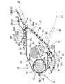
以下、本発明の一実施形態を図面に基づいて説明する。なお、実施形態では、本発明を適用可能なエアバッグ装置として、膝保護用エアバッグ装置Sを例に採り、説明する。膝保護用エアバッグ装置Sは、乗員としての運転者MDの膝K(KL・KR)を保護できるように、図1・4に示すごとく、運転者MDの車両前方側であるステアリングコラム9の下方に配設されている。 Hereinafter, an embodiment of the present invention will be described with reference to the drawings. In the embodiment, a knee protection airbag device S will be described as an example of an airbag device to which the present invention is applicable. As shown in FIGS. 1 and 4, the knee protection airbag device S protects the knee K (KL / KR) of the driver MD as an occupant. It is arranged below.
なお、本明細書における上下、左右、及び、前後は、膝保護用エアバッグ装置Sを車両に搭載させた際の車両の上下・左右・前後に対応するものである。 In addition, the upper and lower sides, the left and right, and the front and rear in this specification correspond to the upper and lower, left and right, and front and rear of the vehicle when the knee protection airbag device S is mounted on the vehicle.
ステアリングコラム9は、図1に示すように、ステアリングホイール8に連結されるコラム本体10と、ステアリングホイール8の下方のコラム本体10を覆うように配設されるコラムカバー13と、を備えて構成されている。コラム本体10は、メインシャフト11と、メインシャフト11の周囲を覆うコラムチューブ12と、を備えて構成されている。 As shown in FIG. 1, the
コラムカバー13は、略四角筒形状の合成樹脂製として、コラム本体10を覆うように、コラム本体10の軸方向に沿って配設されている。コラムカバー13におけるインストルメントパネル(以下「インパネ」と省略する)14から突出する部位の後面13aは、略長方形板状とし、車両前後方向で、後上がりの曲面状に形成されている。 The
膝保護用エアバッグ装置Sは、折り畳まれたエアバッグ51、エアバッグ51に膨張用ガスを供給するインフレーター44、折り畳まれたエアバッグ51とインフレーター44とを収納するとともに車両後方側を開口させたケース17、及び、ケース17における開口18aの車両後方側を覆うエアバッグカバー33を、備えて構成されている。 The knee protection airbag device S houses a folded
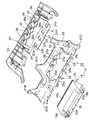
ケース17は、図1〜5に示すように、板金製として、ステアリングコラム9の下部側に配設されている。そして、ケース17は、それぞれ別体に形成されるケース本体18とパネル部材22とを備えて構成されている。ケース本体18とパネル部材22とは、パネル部材22の後述する固着部25を、ケース本体18の後述する周壁部19に溶接固定させることにより、一体化されている。 As shown in FIGS. 1 to 5, the
ケース本体18は、有底の箱形状とされて、略四角筒形状の周壁部19と周壁部19の車両前方側を塞ぐ底壁部20と、を備えるとともに、車両後方側に略長方形状の開口18aを備えて、構成されている。周壁部19における上下で対向する壁部19a・19bの外表面側には、パネル部材22に形成される後述する複数の係止爪部26が、配設されている。また、周壁部19における側方側の壁部19cには、インフレーター44の後述する本体45を挿通可能な挿通孔19dが、形成されている(図3参照)。さらに、底壁部20には、インフレーター44の後述するボルト46cを挿通させるための2つの挿通孔20aが、形成されている。 The
パネル部材22は、エアバッグ51の展開膨張時において、展開膨張したエアバッグ51の車両前方側を支持可能とするもので、ケース本体18の開口18aの周囲を囲むように配設される本体部23と、ケース17を車両のボディ1側に連結させる連結部31と、エアバッグカバー33をケース17に組み付けるための係止爪部26と、を備えて構成されている。 The
本体部23は、ケース本体18の周壁部19における開口18a周縁部位を嵌挿可能とされる嵌挿孔24を、備えている。そして、嵌挿孔24の周縁となる部位には、パネル部材22をケース本体18に固着させるための固着部25が、配設されている。固着部25は、本体部23から車両前方側に突出するように配設されて、ケース本体18の周壁部19の外周面に固着されることとなる。この固着部25は、嵌挿孔24の周縁に、略全周にわたって配設されている。実施形態の場合、固着部25における左右両側に配設される部位25c・25dは、先端付近で周壁部19に固着されることとなり、元部側の部位25eと周壁部19との間に隙間を設けるように、形成されている。そして、この元部側の部位25eと周壁部19との間に、エアバッグカバー33における後述する左・右側壁部38・39が、配設されることとなる(図3参照)。また、本体部23には、図2・5に示すように、エアバッグカバー33の後述する上側壁部36を挿通させる複数(実施形態では4個)の挿通孔23aが、形成されている。 The
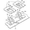
係止爪部26は、固着部25において、それぞれ、周壁部19の上壁部19a側と下壁部側19b側となる部位25a・25bから延設されて、配設されている。係止爪部26は、上壁部19a側と下壁部19b側とに、それぞれ、複数個(実施形態の場合4個ずつ)配設されるもので、係止軸部27と係止片部28とを備えて構成されている。係止軸部27は、固着部25における周壁部19側の部位25a・25bと交差するように突設されて、エアバッグカバー33における組付片としての後述する上側・下側壁部36・37に形成される係止穴部36a・37aに挿通可能とされている。係止片部28は、係止軸部27の先端27aから、ケース17の底壁部20側に向かって屈曲して配設されて、係止穴部36a・37a周縁に係止可能な構成とされている。 The locking
また、係止爪部26は、周壁部19側から係止軸部27の先端27a側にかけて、周壁部19の外側(車両後方側)に向かって隆起する補強用のビード29を、備えている(図6参照)。実施形態の場合、ビード29は、左右方向の中央付近において、固着部25a・25bから、係止軸部27を経て、係止片部28の先端にかけて、配設されている。そして、ビード29は、図2に示すごとく、突出端29a側を、側方から見て三角形状とするように傾斜させて、形成されている。すなわち、ビード29は、係止軸部27の部位において、車両後方側への突出高さを、固着部25a・25b側にかけて大きくして、突出端29a側を傾斜させ、突出端29aにおける車両後方側の面を傾斜面29bとして、構成されている。 In addition, the locking
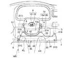
連結部31は、本体部23の縁部に配設されて、実施形態の場合、ケース本体18の上方となる2箇所と、左下隅付近と、右側の上下端付近と、の5箇所に、形成されている。各連結部31を連結させるボディ1側には、図4に示すように、ブラケット4・5・6・7が、配設される。上部側に配設される連結部31A・31Bを連結させるブラケット4・5は、ボディ1側のインパネリインフォースメント2に連結されている。そして、下部側に配設される連結部31C・31Dを連結させるブラケット6・7は、ボディ1側の図示しないセンターブレースやフロントボディピラー等に連結されている。 The connecting portion 31 is disposed at the edge of the
なお、パネル部材22は、板金製とされて、プレス加工により形成されている。そして、実施形態の場合、ビード29は、係止爪部26とともに、プレス加工により、一体的に形成されることとなる。 The
エアバッグカバー33は、オレフィン系等の熱可塑性エラストマーから形成されて、ケース17の車両後方側を覆い可能なように構成され、ケース17に組みつけられている。また、エアバッグカバー33は、アッパパネル14aとロアパネル14bとからなるインパネ14におけるロアパネル14b側に、配設されており、ケース本体18の開口18a付近に配設される扉配設部35と、扉配設部35の周囲においてパネル部材22の車両後方側を覆い可能に配設される被覆部34と、を備えて構成されている。扉配設部35は、扉部42と、扉部42の周縁近傍となる部位に配設される上・下・左・右側壁部36・37・38・39と、を備えて構成されている。 The airbag cover 33 is made of an olefin-based thermoplastic elastomer, is configured to cover the vehicle rear side of the
扉部42は、ケース本体18の開口18aより僅かに大きく形成されて、開口18aを覆う略長方形板状とされている。扉部42は、実施形態では、上下方向に開く2枚の扉部から構成されている。そして、扉部42は、上端及び下端に、開き時の回転中心となるヒンジ部41を配設させるとともに、扉部42の周囲における車両後方側から見て略H字形状となる部位に、薄肉の破断予定部40を、配設させて構成されている。 The
上側壁部36、下側壁部37、左側壁部38、及び、右側壁部39は、それぞれ、ケース本体18における周壁部19の外周側に隣接して、周壁部19に沿って車両前方側に突出するように、配設されている。上側壁部36は、実施形態の場合、係止爪部26に対応して、4個配設されている。そして、実施形態の場合、周壁部19の上壁部19a近傍に配設される上側壁部36と、下壁部19b近傍に配設される下側壁部37と、が、エアバッグカバー33をケース17に組み付ける組付片とされている。上側・下側壁部36・37には、それぞれ、係止爪部26を係止させるための複数の長方形状に開口した係止穴部36a・37aが、形成されている。なお、各係止穴部36a・37aの内周面には、各係止爪部26に係止された後の各係止爪部の係止片部28からの外れを防止する外れ防止片36b・37bが、車両前方側から後方側へ突設されている。 The upper
インフレーター44は、図2・3に示すように、軸方向を車両の左右方向に沿って配設されるシリンダタイプとして構成され、略円柱状の本体45とディフューザー46とを備えて構成されている。本体45の一端側には、複数のガス吐出口45aが、配設されている。そして、本体45の他端側には、作動信号入力用のリード線49を結線させたコネクタ48が、接続されることとなる。ディフューザー46は、本体45を覆い可能な略円筒状の板金製の保持筒部46aと、保持筒部46aから突出する複数(実施形態では2本)のボルト46cと、を備えて構成されている。保持筒部46aは、本体45のガス吐出口45aから吐出される膨張用ガスを流出可能な複数のガス流出口46bを、車両搭載状態の保持筒部46aにおける車両後方側の面に、開口させて構成されている。 As shown in FIGS. 2 and 3, the
なお、このインフレーター44には、車両に搭載されたエアバッグ作動回路が、車両の前面衝突を見地した際に、ステアリングホイール8に搭載された図示しないエアバッグ装置とともに、リード線49を介して、作動信号が入力されることとなる。 The inflator 44 has an airbag operating circuit mounted on the vehicle via a
エアバッグ51は、可撓性を有したポリエステルやポリアミド糸等からなる織布から形成されて、展開膨張完了時の形状を、図1・4の二点鎖線に示すごとく、略長方形板状とするとともに、乗員としての運転者MDの膝KL・KRを保護可能な左右方向の幅寸法を備える形状とされている。また、膨張完了時のエアバッグ51の下端側の部位には、図3に示すように、2つの挿通孔51a・51aと、1つの挿通孔51bと、が形成されている。挿通孔51a・51aは、インフレーター44の各ボルト46cを挿通させるものであり、挿通孔51bは、インフレーター44の本体45を挿通させるものである。そして、エアバッグ51は、挿通孔51bからインフレーター44の本体45を突出させて、各挿通孔51aの周縁を、保持筒部46aとケース本体18の底壁部20とに挟持されて、ケース本体18に取り付けられている。 The
次に、実施形態の膝保護用エアバッグ装置Sの車両への搭載について述べる。まず、挿通孔51aからボルト46cを突出させ、挿通孔51bから本体45の端部を突出させるように、エアバッグ51内に、インフレーター44を収納させて、エアバッグ51を折り畳む。次に、折り崩れ防止用の破断可能な図示しないラッピングフィルムにより、エアバッグ51をくるむ。このとき、挿通孔51a・51bから突出したインフレーター44のボルト46cや本体45の端部は、ラッピングフィルムから突出させておく。 Next, the mounting of the knee protection airbag device S of the embodiment on a vehicle will be described. First, the
次いで、インフレーター44の各ボルト46cを挿通孔20aから突出させてナット47止めするとともに、インフレーター本体45の端部を挿通孔19dから突出させるようにして、インフレーター44を、折り畳まれたエアバッグ51とともに、ケース本体18内に収納させる。 Next, the bolts 46c of the inflator 44 are protruded from the
その後、ケース17に、エアバッグカバー33を組み付ける。具体的には、図7のAに示すごとく、各上側壁部36をパネル部材22の本体部23に形成される挿通孔23aに挿通させるようにして、エアバッグカバー33をケース17側に移動させれば、上側壁部36(下側壁部37)が、各係止爪部26におけるビード29の突出端29a側の傾斜面29bに沿って、先端36c側を上壁部19aに対して拡開されつつ、係止爪部26に対して、スライドするように移動することとなる(図7のB参照)。そして、係止軸部27の位置に各係止穴部36a(37a)が到達すれば、図7のCに示すごとく、上側壁部36(下側壁部37)が自動的に復元して、各係止穴部36a(37a)の周縁に、係止片部28が、係止されることとなって、ケース17にエアバッグカバー33を組み付けることができる。なお、実施形態では、係止穴部36a(37a)に、外れ防止片36b(37b)が配設されているが、この外れ防止片36b(37b)は、上側壁部36(下側壁部37)の復元時に、上側壁部36(下側壁部37)の移動方向とは逆にケース17外方に向かって撓んで、係止片部28を挿通させることができ、係止爪部26における係止片部28を、係止穴部36a(37a)周縁に、支障なく、係止させることができる。なお、仮に、外れ防止片36b・37bが係止片部28と干渉して、上側・下側壁部36・37が復元し難くとも、指等により上側・下側壁部36・37を周壁部19側に押せば、上側・下側壁部36・37を容易に復元させることができる。 Thereafter, the
そして、ケース17の各連結部31を、ブラケット4・5・6・7を利用してボディ1側に取付固定し、同時に、リード線49を結線させたコネクタ48を、インフレーター本体45に接続させる。その後、インパネ14やアンダーカバー15(図1・2参照)を取り付ければ、エアバッグ装置Sを車両に搭載することができる。 Then, each connecting portion 31 of the
エアバッグ装置Sの車両への搭載後、リード線49を経てインフレーター本体45に作動信号が入力されれば、インフレーター44のガス吐出口45aから膨張用ガスが吐出され、膨張用ガスが、ディフューザー46のガス流出口46bを経て、エアバッグ51内に流入することとなる。そして、エアバッグ51は、膨張して、図示しないラッピング材を破断させ、エアバッグカバー33の扉部42を押圧し、破断予定部40を破断させることとなる。そして、扉部42が、ヒンジ部41を回転中心として上下に開くこととなり、エアバッグ51が、図1・4の二点鎖線で示すごとく、展開膨張することとなる。 If the operation signal is input to the
そして、実施形態のエアバッグ装置Sでは、ケース17に配設される係止爪部26が、周壁部19(固着部25a・25b)側から係止軸部27の先端27a側にかけて、周壁部19の外側へ隆起する補強用のビード29を備える構成である。そのため、係止軸部27の周壁部19側(固着部25a・25b)に対する曲げ剛性を高めることができて、エアバッグカバー33をケース17に対して強固に組み付けることができる。 And in the airbag apparatus S of embodiment, the latching
また、実施形態のエアバッグ装置Sでは、ビード29が、周壁部19側から係止軸部27の先端27a側にかけて、突出端29a側を、側方から見て三角形状とするように傾斜させて、構成されていることから、エアバッグカバー33をケース17に組み付ける際に、組付片としての上側・下側壁部36・37の先端が係止爪部26と当接しても、ビード29の突出端29a側の傾斜面29bにより上側・下側壁部36・37の先端を案内させて、周壁部19側と離隔するように、容易に拡開させることができる。すなわち、実施形態のエアバッグ装置Sでは、エアバッグカバー33の上側・下側壁部36・37を、ケース17の底壁部20側にスライドさせれば、上側・下側壁部36・37が、ビード29の突出端29a側の傾斜面29bに沿って自動的に周壁部19側から離れるように押され、係止爪部26が係止穴部36a・37aの位置に到達すれば、上側・下側壁部36・37が自動的に復元等して、係止爪部26が係止穴部36a・37a周縁に簡素に係止されることとなる。そのため、係止爪部26を上側・下側壁部36・37の係止穴部36a・37a周縁に容易に係止させることができて、エアバッグカバー33を、ケース17に容易に組み付けることができる。 Further, in the airbag device S of the embodiment, the
従って、実施形態のエアバッグ装置Sでは、エアバッグカバー33をケース17に対して強固に組み付けることが可能であり、かつ、エアバッグカバー33のケース17への組付作業が容易である。 Therefore, in the airbag apparatus S of the embodiment, the
なお、実施形態のエアバッグ装置Sでは、ビード29が、係止軸部27の部位において、車両後方側への突出高さを、固着部25a・25b側にかけて大きくするように、形成されている。すなわち、ビード29は、各係止軸部27と固着部25a・25bとの接合部位となる部位が、突出高さを最も大きくするように、形成されている。そのため、係止軸部27の周壁部19側(固着部25a・25b)に対する曲げ剛性を、一層、高めることが可能となる。 In the airbag apparatus S of the embodiment, the
なお、実施形態では、着座した乗員MDの膝Kの前方に配設される膝保護用エアバッグ装置Sを例に採り説明したが、本発明を適用可能なエアバッグ装置はこれに限られるものではなく、助手席前方に配設される助手席用エアバッグ装置等にも、適用可能である。 In the embodiment, the knee protection airbag device S disposed in front of the knee K of the seated occupant MD is taken as an example, but the airbag device to which the present invention is applicable is limited to this. Instead, the present invention can also be applied to an airbag device for a passenger seat disposed in front of the passenger seat.
17…ケース、
18…ケース本体、
18a…開口、
19…周壁部、
20…底壁部、
26…係止爪部、
27…係止軸部、
28…係止片部、
29…ビード、
29a…突出端、
29b…傾斜面、
33…エアバッグカバー、
36…上側壁部(組付片)、
36a…係止穴部、
37…下側壁部(組付片)、
37a…係止穴部、
42…扉部、
44…インフレーター、
51…エアバッグ、
K(KL・KR)…膝、
MD…乗員、
S…膝保護用エアバッグ装置。17 ... Case,
18 ... the case body,
18a ... opening,
19 ... the peripheral wall,
20 ... bottom wall,
26: locking claw,
27 ... locking shaft part,
28 ... locking piece,
29 ... Bead,
29a ... protruding end,
29b ... inclined surface,
33 ... Airbag cover,
36 ... upper side wall (assembly piece),
36a ... Locking hole,
37 ... Lower side wall (attachment piece),
37a ... Locking hole,
42 ... the door,
44 ... Inflator,
51 ... Airbag,
K (KL / KR) ... knees,
MD ... Crew,
S: Air bag device for knee protection.
Claims (3)
Translated fromJapanese該ケースの開口を覆って前記エアバッグの展開膨張時に開き可能とされる扉部を有する構成のエアバッグカバーと、
を備えるとともに、
前記ケースが、前記開口の周囲の周壁部に配設されて前記エアバッグカバーを組み付けるための係止爪部を、備えて構成され、
前記エアバッグカバーが、前記係止爪部を使用して前記ケースに組付可能とするように、前記周壁部の外側近傍で前記周壁部に沿うように配設されて、前記係止爪部を挿通可能な係止穴部を有した組付片を、備えて構成され、
前記係止爪部が、
前記周壁部と交差するように突設されて、前記係止穴部に挿通可能とされる係止軸部と、
該係止軸部の先端から、前記ケースの底部側に向かって屈曲して配設されて、前記係止穴部周縁に係止可能とされる係止片部と、
を備える構成のエアバッグ装置において、
前記係止爪部が、前記周壁部側から前記係止軸部の先端側にかけて、前記周壁部の外側へ隆起する補強用のビードを備え、
該ビードが、前記周壁部側から前記係止軸部の先端側にかけて、突出端側を、側方から見て三角形状とするように傾斜させて、形成され、
前記ビードにおける前記突出端側の傾斜面が、前記エアバッグカバーの前記ケースへの組付時において、前記ケース側に移動する前記エアバッグカバーにおける前記組付片の先端を、前記周壁部から離隔させて拡開させるように案内可能に、構成されていることを特徴とするエアバッグ装置。A case having a bottomed box shape that houses a folded airbag and an inflator that supplies inflation gas to the airbag, and includes an opening that can project the airbag; and
An airbag cover configured to cover the opening of the case and have a door portion that can be opened when the airbag is deployed and inflated;
With
The case is configured to include a locking claw portion that is disposed on a peripheral wall portion around the opening and to assemble the airbag cover,
The airbag cover is disposed along the peripheral wall portion in the vicinity of the outside of the peripheral wall portion so that the airbag cover can be assembled to the case using the locking claw portion. Is provided with an assembly piece having a locking hole that can be inserted therethrough,
The locking claw portion is
A locking shaft portion that is projected so as to intersect with the peripheral wall portion, and can be inserted into the locking hole portion,
A locking piece portion that is bent from the front end of the locking shaft portion toward the bottom side of the case and can be locked to the periphery of the locking hole portion;
In an airbag device configured to include:
The locking claw part includes a reinforcing bead that protrudes from the peripheral wall part side to the distal end side of the locking shaft part to the outside of the peripheral wall part,
The bead is formed so as to be inclined from the peripheral wall portion side to the distal end side of the locking shaft portion so that the protruding end side has a triangular shape when viewed from the side,
The inclined surface on the protruding end side of the bead separates the tip of the assembly piece in the airbag cover that moves to the case side from the peripheral wall portion when the airbag cover is assembled to the case. The airbag device isconfigured to be able to be guided so as to be expanded .
該パネル部材に、前記組付片を挿通させる挿通孔が、形成されていることを特徴とする請求項1又は2に記載のエアバッグ装置。The airbag device according to claim 1, wherein an insertion hole through which the assembly piece is inserted is formed in the panel member.
Priority Applications (1)
| Application Number | Priority Date | Filing Date | Title |
|---|---|---|---|
| JP2003335577AJP4096855B2 (en) | 2003-09-26 | 2003-09-26 | Airbag device |
Applications Claiming Priority (1)
| Application Number | Priority Date | Filing Date | Title |
|---|---|---|---|
| JP2003335577AJP4096855B2 (en) | 2003-09-26 | 2003-09-26 | Airbag device |
Publications (2)
| Publication Number | Publication Date |
|---|---|
| JP2005096698A JP2005096698A (en) | 2005-04-14 |
| JP4096855B2true JP4096855B2 (en) | 2008-06-04 |
Family
ID=34462923
Family Applications (1)
| Application Number | Title | Priority Date | Filing Date |
|---|---|---|---|
| JP2003335577AExpired - Fee RelatedJP4096855B2 (en) | 2003-09-26 | 2003-09-26 | Airbag device |
Country Status (1)
| Country | Link |
|---|---|
| JP (1) | JP4096855B2 (en) |
Cited By (1)
| Publication number | Priority date | Publication date | Assignee | Title |
|---|---|---|---|---|
| US11351945B1 (en)* | 2021-01-20 | 2022-06-07 | Faurecia Interior Systems, Inc. | Knee airbag cover |
Families Citing this family (5)
| Publication number | Priority date | Publication date | Assignee | Title |
|---|---|---|---|---|
| JP4640053B2 (en)* | 2005-09-07 | 2011-03-02 | トヨタ自動車株式会社 | Knee protection bag integrated airbag device for passenger seat |
| JP4710862B2 (en) | 2007-04-02 | 2011-06-29 | 豊田合成株式会社 | Air bag device for knee protection |
| DE102010039899B4 (en)* | 2010-08-27 | 2013-10-10 | TAKATA Aktiengesellschaft | Device for fastening a holding part of a gas bag module of a vehicle occupant restraint system with a connecting part of a vehicle structure |
| JP5915340B2 (en)* | 2012-04-04 | 2016-05-11 | 三菱自動車エンジニアリング株式会社 | Fitting structure between air bag grid and its adjacent members |
| JP6169902B2 (en)* | 2013-06-19 | 2017-07-26 | タカタ株式会社 | Airbag device |
- 2003
- 2003-09-26JPJP2003335577Apatent/JP4096855B2/ennot_activeExpired - Fee Related
Cited By (1)
| Publication number | Priority date | Publication date | Assignee | Title |
|---|---|---|---|---|
| US11351945B1 (en)* | 2021-01-20 | 2022-06-07 | Faurecia Interior Systems, Inc. | Knee airbag cover |
Also Published As
| Publication number | Publication date |
|---|---|
| JP2005096698A (en) | 2005-04-14 |
Similar Documents
| Publication | Publication Date | Title |
|---|---|---|
| JP3900051B2 (en) | Air bag device for knee protection | |
| JP4797697B2 (en) | Air bag device for knee protection | |
| US7185912B2 (en) | Knee protection airbag device | |
| JP4710862B2 (en) | Air bag device for knee protection | |
| JP4332183B2 (en) | Knee airbag device with column and method of assembling a steering column having the same to a vehicle | |
| EP1479571A1 (en) | Occupant leg protection apparatus | |
| KR101637207B1 (en) | Safety apparaus for vehicle | |
| JP7115411B2 (en) | Airbag device for knee protection | |
| JP4096855B2 (en) | Airbag device | |
| JP3807310B2 (en) | Air bag device for knee protection | |
| JP4053385B2 (en) | Air bag device for knee protection | |
| JP4053384B2 (en) | Air bag device for knee protection | |
| JP4466471B2 (en) | Air bag device for knee protection | |
| JP4096856B2 (en) | Air bag device for knee protection | |
| JP4254451B2 (en) | Air bag device for knee protection | |
| JP3864855B2 (en) | Air bag device for knee protection | |
| JP2005280556A (en) | Hood panel | |
| JP4139170B2 (en) | Air bag device for knee protection | |
| JP4160892B2 (en) | Air bag device for knee protection | |
| JP4013679B2 (en) | Air bag device for knee protection | |
| JP2005247001A (en) | Airbag device for protecting knee | |
| JP4214909B2 (en) | Air bag device for knee protection | |
| JP2005263153A (en) | Air bag device for knee protection | |
| JP3780892B2 (en) | Air bag device for knee protection | |
| CN100398363C (en) | airbag device |
Legal Events
| Date | Code | Title | Description |
|---|---|---|---|
| A621 | Written request for application examination | Free format text:JAPANESE INTERMEDIATE CODE: A621 Effective date:20051025 | |
| A977 | Report on retrieval | Free format text:JAPANESE INTERMEDIATE CODE: A971007 Effective date:20071126 | |
| A131 | Notification of reasons for refusal | Free format text:JAPANESE INTERMEDIATE CODE: A131 Effective date:20071127 | |
| A521 | Written amendment | Free format text:JAPANESE INTERMEDIATE CODE: A523 Effective date:20080118 | |
| TRDD | Decision of grant or rejection written | ||
| A01 | Written decision to grant a patent or to grant a registration (utility model) | Free format text:JAPANESE INTERMEDIATE CODE: A01 Effective date:20080219 | |
| A61 | First payment of annual fees (during grant procedure) | Free format text:JAPANESE INTERMEDIATE CODE: A61 Effective date:20080303 | |
| R150 | Certificate of patent or registration of utility model | Ref document number:4096855 Country of ref document:JP Free format text:JAPANESE INTERMEDIATE CODE: R150 Free format text:JAPANESE INTERMEDIATE CODE: R150 | |
| FPAY | Renewal fee payment (event date is renewal date of database) | Free format text:PAYMENT UNTIL: 20110321 Year of fee payment:3 | |
| FPAY | Renewal fee payment (event date is renewal date of database) | Free format text:PAYMENT UNTIL: 20120321 Year of fee payment:4 | |
| FPAY | Renewal fee payment (event date is renewal date of database) | Free format text:PAYMENT UNTIL: 20120321 Year of fee payment:4 | |
| FPAY | Renewal fee payment (event date is renewal date of database) | Free format text:PAYMENT UNTIL: 20130321 Year of fee payment:5 | |
| FPAY | Renewal fee payment (event date is renewal date of database) | Free format text:PAYMENT UNTIL: 20140321 Year of fee payment:6 | |
| LAPS | Cancellation because of no payment of annual fees |