JP4096262B2 - Lens barrel and imaging device - Google Patents
Lens barrel and imaging deviceDownload PDFInfo
- Publication number
- JP4096262B2 JP4096262B2JP2004114393AJP2004114393AJP4096262B2JP 4096262 B2JP4096262 B2JP 4096262B2JP 2004114393 AJP2004114393 AJP 2004114393AJP 2004114393 AJP2004114393 AJP 2004114393AJP 4096262 B2JP4096262 B2JP 4096262B2
- Authority
- JP
- Japan
- Prior art keywords
- gear
- lens
- tooth portion
- diameter tooth
- detection plate
- Prior art date
- Legal status (The legal status is an assumption and is not a legal conclusion. Google has not performed a legal analysis and makes no representation as to the accuracy of the status listed.)
- Expired - Lifetime
Links
- 238000003384imaging methodMethods0.000titleclaimsdescription24
- 238000001514detection methodMethods0.000claimsdescription96
- 230000003287optical effectEffects0.000claimsdescription36
- 229920003002synthetic resinPolymers0.000claimsdescription10
- 239000000057synthetic resinSubstances0.000claimsdescription10
- 239000002184metalSubstances0.000claimsdescription3
- 230000002093peripheral effectEffects0.000description3
- 238000010586diagramMethods0.000description2
- 238000006073displacement reactionMethods0.000description2
- 229920002430Fibre-reinforced plasticPolymers0.000description1
- 230000004888barrier functionEffects0.000description1
- 239000000428dustSubstances0.000description1
- 239000011151fibre-reinforced plasticSubstances0.000description1
- 239000003365glass fiberSubstances0.000description1
- 229920005668polycarbonate resinPolymers0.000description1
- 239000004431polycarbonate resinSubstances0.000description1
Images


Classifications
- G—PHYSICS
- G02—OPTICS
- G02B—OPTICAL ELEMENTS, SYSTEMS OR APPARATUS
- G02B7/00—Mountings, adjusting means, or light-tight connections, for optical elements
- G02B7/02—Mountings, adjusting means, or light-tight connections, for optical elements for lenses
- G02B7/021—Mountings, adjusting means, or light-tight connections, for optical elements for lenses for more than one lens
- H—ELECTRICITY
- H04—ELECTRIC COMMUNICATION TECHNIQUE
- H04N—PICTORIAL COMMUNICATION, e.g. TELEVISION
- H04N23/00—Cameras or camera modules comprising electronic image sensors; Control thereof
- H04N23/50—Constructional details
- H04N23/55—Optical parts specially adapted for electronic image sensors; Mounting thereof
- G—PHYSICS
- G02—OPTICS
- G02B—OPTICAL ELEMENTS, SYSTEMS OR APPARATUS
- G02B7/00—Mountings, adjusting means, or light-tight connections, for optical elements
- G02B7/02—Mountings, adjusting means, or light-tight connections, for optical elements for lenses
- G02B7/04—Mountings, adjusting means, or light-tight connections, for optical elements for lenses with mechanism for focusing or varying magnification
- G02B7/10—Mountings, adjusting means, or light-tight connections, for optical elements for lenses with mechanism for focusing or varying magnification by relative axial movement of several lenses, e.g. of varifocal objective lens
- G02B7/102—Mountings, adjusting means, or light-tight connections, for optical elements for lenses with mechanism for focusing or varying magnification by relative axial movement of several lenses, e.g. of varifocal objective lens controlled by a microcomputer
- G—PHYSICS
- G03—PHOTOGRAPHY; CINEMATOGRAPHY; ANALOGOUS TECHNIQUES USING WAVES OTHER THAN OPTICAL WAVES; ELECTROGRAPHY; HOLOGRAPHY
- G03B—APPARATUS OR ARRANGEMENTS FOR TAKING PHOTOGRAPHS OR FOR PROJECTING OR VIEWING THEM; APPARATUS OR ARRANGEMENTS EMPLOYING ANALOGOUS TECHNIQUES USING WAVES OTHER THAN OPTICAL WAVES; ACCESSORIES THEREFOR
- G03B17/00—Details of cameras or camera bodies; Accessories therefor
- G03B17/02—Bodies
- G03B17/04—Bodies collapsible, foldable or extensible, e.g. book type
- B—PERFORMING OPERATIONS; TRANSPORTING
- B29—WORKING OF PLASTICS; WORKING OF SUBSTANCES IN A PLASTIC STATE IN GENERAL
- B29K—INDEXING SCHEME ASSOCIATED WITH SUBCLASSES B29B, B29C OR B29D, RELATING TO MOULDING MATERIALS OR TO MATERIALS FOR MOULDS, REINFORCEMENTS, FILLERS OR PREFORMED PARTS, e.g. INSERTS
- B29K2083/00—Use of polymers having silicon, with or without sulfur, nitrogen, oxygen, or carbon only, in the main chain, as moulding material
- B—PERFORMING OPERATIONS; TRANSPORTING
- B29—WORKING OF PLASTICS; WORKING OF SUBSTANCES IN A PLASTIC STATE IN GENERAL
- B29L—INDEXING SCHEME ASSOCIATED WITH SUBCLASS B29C, RELATING TO PARTICULAR ARTICLES
- B29L2023/00—Tubular articles
- B29L2023/005—Hoses, i.e. flexible
Landscapes
- Physics & Mathematics (AREA)
- General Physics & Mathematics (AREA)
- Engineering & Computer Science (AREA)
- Optics & Photonics (AREA)
- Multimedia (AREA)
- Signal Processing (AREA)
- General Engineering & Computer Science (AREA)
- Lens Barrels (AREA)
Description
Translated fromJapanese本発明はレンズ鏡筒および撮像装置に関する。 The present invention relates to a lens barrel and an imaging device.
デジタルスチルカメラやデジタルビデオカメラ等の撮像装置には、鏡筒内に配設されたレンズを含む撮影光学系と、該撮像光学系で結像された被写体像を撮像する撮像素子とを備えたレンズ鏡筒が設けられている。
このようなレンズ鏡筒は、光軸方向にレンズを移動可能に支持し回転駆動力が供給されることで前記レンズを光軸方向に移動させるレンズ移動機構と、前記レンズ移動機構に回転駆動力を供給するレンズ駆動機構とを有している。
レンズ駆動機構は、出力軸を有するモータと、出力軸に設けられた駆動ギアに噛合しモータの動力をレンズ移動機構に供給するギア列などを備えている。
そして、レンズ移動機構を制御するに際して、モータの回転量や回転方向が検知され、この検知は、モータの出力軸やギア列を構成する回転軸に設けられた検知板と、この検知板の回転を検出する検出器などを用いて行われており、この場合、小型化を図ろうとすると検知板とギア列との干渉が問題となる。
モータの出力軸に検知板を設ける従来構造として、モータとして、モータケースの両端からそれぞれ出力軸を突出するものを用い、一方の出力軸に駆動ギアを設け、他方の出力軸に検知板を設け、検知板とギア列の支軸との干渉を阻止する構成が提案されている(例えば特許文献1参照)。
また、ギア列を構成する回転軸に検知板を設ける従来構造として、ギア列のギアは多くの場合両持ち式で支持されていることから、駆動ギアに噛合する専用の回転検出用ギアを新たに設け、この回転検出用ギアと一体に回転する検知板を設け、検知板とギア列の支軸との干渉を阻止する構成が提案されている(例えば特許文献2参照)。
Such a lens barrel includes a lens moving mechanism that moves the lens in the optical axis direction by supporting the lens so that the lens can be moved in the optical axis direction, and a rotational driving force applied to the lens moving mechanism. And a lens driving mechanism for supplying
The lens drive mechanism includes a motor having an output shaft, a gear train that meshes with a drive gear provided on the output shaft, and supplies the power of the motor to the lens moving mechanism.
When the lens moving mechanism is controlled, the rotation amount and rotation direction of the motor are detected. This detection is performed by detecting a detection plate provided on the output shaft of the motor and a rotation shaft constituting the gear train, and rotation of the detection plate. In this case, interference between the detection plate and the gear train becomes a problem when miniaturization is attempted.
As a conventional structure in which a detection plate is provided on the output shaft of the motor, a motor that protrudes from the both ends of the motor case is used, a drive gear is provided on one output shaft, and a detection plate is provided on the other output shaft. A configuration that prevents interference between the detection plate and the support shaft of the gear train has been proposed (see, for example, Patent Document 1).
In addition, as a conventional structure in which a detection plate is provided on the rotating shaft that constitutes the gear train, the gear train gears are often supported in a dual-supported manner, so a dedicated rotation detection gear that meshes with the drive gear is newly added. A configuration is proposed in which a detection plate that rotates integrally with the rotation detection gear is provided to prevent interference between the detection plate and the support shaft of the gear train (see, for example, Patent Document 2).
しかしながら、前者の構成では、モータの他方の出力軸側に検知板の占有スペースを確保しなくてはならず小型化を図る上で不利があった。また、後者の構成では、モータの回転を検出するために専用の回転検出用ギアを付加しなくてならず、部品点数の削減や小型化を図る上で不利があった。
本発明は、このような事情に鑑みなされたものであり、その目的は部品点数の削減および小型化を図る上で有利なレンズ鏡筒および撮像装置を提供することにある。However, in the former configuration, it is necessary to secure an occupied space for the detection plate on the other output shaft side of the motor, which is disadvantageous in reducing the size. In the latter configuration, a dedicated rotation detection gear must be added to detect the rotation of the motor, which is disadvantageous in reducing the number of parts and reducing the size.
The present invention has been made in view of such circumstances, and an object of the present invention is to provide a lens barrel and an imaging device that are advantageous in reducing the number of parts and reducing the size.
上述の目的を達成するため、本発明のレンズ鏡筒は、ベースと、前記ベースに設けられた鏡筒とを有し、前記鏡筒には、レンズをその光軸方向に移動可能に支持し回転駆動力が供給されることで前記レンズを光軸方向に移動させるレンズ移動機構が設けられ、前記ベースには、前記レンズ移動機構に回転駆動力を供給するレンズ駆動機構が設けられ、前記レンズ駆動機構は、出力軸を有するモータと、前記出力軸に設けられた駆動ギアと、前記駆動ギアに噛合し前記モータの動力を前記レンズ移動機構に供給するギア列とを有し、さらに、前記モータの回転量を検出する検出機構が設けられたレンズ鏡筒であって、前記出力軸は前記モータのケースの一端から突出して設けられ、前記検出機構は、前記出力軸の先端に固定され該出力軸と一体に回転する検知板と、前記検知板の回転を検出する検出器を含んで構成され、前記駆動ギアは前記出力軸の長手方向の中間部に固定され、前記ギア列は、前記ベースに取着され合成樹脂によりモールド成型されたホルダの内部に収容され、前記ホルダの内部は該ホルダに取着された蓋板により閉塞され、前記ギア列は、第1ギアと第2ギアとを含んで構成され、前記第1ギアは小径歯部と大径歯部を有し、前記第2ギアは小径歯部と大径歯部を有し、前記第1ギアは、前記ホルダで片持ち支持された支軸上で回転可能に配設され、前記第1ギアは、前記検知板と前記ケースとの間であって、該検知板側に前記小径歯部を向け、前記大径歯部が前記駆動ギアに歯合するように配設され、前記支軸は合成樹脂製で前記ホルダと一体にモールド成型されるとともに、該支軸はその先端面が前記第1ギアが前記検知板に臨む面と略面一に構成され、前記モータの出力軸の長手方向から見て、前記検知板の輪郭内に前記第1ギアの軸心が位置し、前記第2ギアは、該第2ギアの前記大径歯部を前記第1ギアの前記小径歯部に歯合して、前記大径歯部を前記検知板側に向けて配設され、前記第1ギアの大径歯部と前記第2ギアの大径歯部との隙間は、前記第1ギアの前記検知板側の面と該検知板との隙間よりも小さいことを特徴とするレンズ鏡筒。
本発明の撮像装置は、レンズを有するレンズ鏡筒と、前記レンズで導かれた被写体像を撮像する撮像素子とを備え、前記レンズ鏡筒は、ベースと、前記ベースに設けられた鏡筒とを有し、前記鏡筒には、前記レンズをその光軸方向に移動可能に支持し回転駆動力が供給されることで前記レンズを光軸方向に移動させるレンズ移動機構が設けられ、前記ベースには、前記レンズ移動機構に回転駆動力を供給するレンズ駆動機構が設けられ、前記レンズ駆動機構は、出力軸を有するモータと、前記出力軸に設けられた駆動ギアと、前記駆動ギアに噛合し前記モータの動力を前記レンズ移動機構に供給するギア列とを有し、さらに、前記モータの回転量を検出する検出機構が設けられた撮像装置であって、前記出力軸は前記モータのケースの一端から突出して設けられ、前記検出機構は、前記出力軸の先端に固定され該出力軸と一体に回転する検知板と、前記検知板の回転を検出する検出器を含んで構成され、前記駆動ギアは前記出力軸の長手方向の中間部に固定され、前記ギア列は、前記ベースに取着され合成樹脂によりモールド成型されたホルダの内部に収容され、前記ホルダの内部は該ホルダに取着された蓋板により閉塞され、前記ギア列は、第1ギアと第2ギアとを含んで構成され、前記第1ギアは小径歯部と大径歯部を有し、前記第2ギアは小径歯部と大径歯部を有し、前記第1ギアは、前記ホルダで片持ち支持された支軸上で回転可能に配設され、前記第1ギアは、前記検知板と前記ケースとの間であって、該検知板側に前記小径歯部を向け、前記大径歯部が前記駆動ギアに歯合するように配設され、前記支軸は合成樹脂製で前記ホルダと一体にモールド成型されるとともに、該支軸はその先端面が前記第1ギアが前記検知板に臨む面と略面一に構成され、前記モータの出力軸の長手方向から見て、前記検知板の輪郭内に前記第1ギアの軸心が位置し、前記第2ギアは、該第2ギアの前記大径歯部を前記第1ギアの前記小径歯部に歯合して、前記大径歯部を前記検知板側に向けて配設され、前記第1ギアの大径歯部と前記第2ギアの大径歯部との隙間は、前記第1ギアの前記検知板側の面と該検知板との隙間よりも小さいことを特徴とする。
In order to achieve the above object, a lens barrel of the present invention has a base and a lens barrel provided on the base, and the lens barrel supports the lens so as to be movable in the optical axis direction. A lens moving mechanism that moves the lens in the direction of the optical axis when a rotational driving force is supplied is provided, and a lens driving mechanism that supplies a rotational driving force to the lens moving mechanism is provided on the base. The drive mechanism includes a motor having an output shaft, a drive gear provided on the output shaft, and a gear train that meshes with the drive gear and supplies power of the motor to the lens moving mechanism. A lens barrel provided with a detection mechanism for detecting a rotation amount of the motor,wherein the output shaft projects from one end of a case of the motor, and the detection mechanism is fixed to a tip of the output shaft; Integrated with output shaft It comprises a detector plate that rotates, and a detector that detects the rotation of the detector plate, the drive gear is fixed to the intermediate portion in the longitudinal direction of the output shaft, and the gear train is attached to the base. The holder is housed in a holder molded with synthetic resin, the inside of the holder is closed by a cover plate attached to the holder, and the gear train includes a first gear and a second gear. The first gear has a small-diameter tooth portion and a large-diameter tooth portion, the second gear has a small-diameter tooth portion and a large-diameter tooth portion, and the first gear is cantilevered by the holder. The first gear is disposed between the detection plate and the case, the small-diameter tooth portion is directed to the detection plate side, and the large-diameter tooth portion is the drive gear. The support shaft is made of synthetic resin and is molded integrally with the holder. In addition, the support shaft is configured such that a tip surface thereof is substantially flush with a surface where the first gear faces the detection plate, and the support shaft has the detection plate within the contour of the detection plate when viewed from the longitudinal direction of the output shaft of the motor. The shaft center of the first gear is located, and the second gear meshes the large-diameter tooth portion of the second gear with the small-diameter tooth portion of the first gear, and detects the large-diameter tooth portion. The gap between the large-diameter tooth portion of the first gear and the large-diameter tooth portion of the second gear is arranged toward the plate side, and the detection plate-side surface of the first gear and the detection plate A lens barrel characterizedby being smaller than the gap .
An imaging apparatus according to the present invention includes a lens barrel having a lens and an imaging element that captures a subject image guided by the lens. The lens barrel includes a base, and a lens barrel provided on the base. The lens barrel is provided with a lens moving mechanism that supports the lens so that the lens can move in the optical axis direction and supplies the rotational driving force to move the lens in the optical axis direction. Includes a lens driving mechanism that supplies a rotational driving force to the lens moving mechanism, and the lens driving mechanism meshes with a motor having an output shaft, a driving gear provided on the output shaft, and the driving gear. And a gear train for supplying power of the motor to the lens moving mechanism, and further provided with a detection mechanism for detecting the rotation amount of the motor,wherein the output shaft is a case of the motor One end of The detection mechanism includes a detection plate that is fixed to the tip of the output shaft and rotates integrally with the output shaft, and a detector that detects rotation of the detection plate, and the drive gear is The gear train is housed in a holder attached to the base and molded by a synthetic resin, and the inside of the holder is attached to the holder. Closed by a cover plate, the gear train includes a first gear and a second gear, the first gear has a small-diameter tooth portion and a large-diameter tooth portion, and the second gear has a small-diameter tooth portion. The first gear is rotatably arranged on a support shaft that is cantilevered by the holder, and the first gear is disposed between the detection plate and the case. The small-diameter tooth portion is directed to the detection plate side, and the large-diameter tooth portion is connected to the drive gear. The support shaft is made of synthetic resin and is molded integrally with the holder, and the support shaft has a tip surface substantially flush with the surface where the first gear faces the detection plate. The shaft center of the first gear is located within the contour of the detection plate when viewed from the longitudinal direction of the output shaft of the motor, and the second gear is the large-diameter tooth portion of the second gear. Is engaged with the small-diameter tooth portion of the first gear, the large-diameter tooth portion is disposed toward the detection plate, and the large-diameter tooth portion of the first gear and the large diameter of the second gear are arranged. The gap with the tooth part is smaller than the gap between the detection plate side surface of the first gear and the detection plate .
本発明によれば、モータの出力軸に検知板を取り付け、出力軸の駆動ギアに噛合する第1ギアを片持ちでホルダで支持するようにしたので、駆動ギアの前方スペースを利用して検知板を配設できる。したがって、検知板を配設するにあたり検知板の占有スペースを最小限に抑えることができ小型化を図る上で有利となる。また、モータの回転を検出するために専用の回転検出用ギアを設ける必要はなく、したがって、部品点数の削減化を図る上でも有利となる。 According to the present invention, the detection plate is attached to the output shaft of the motor, and the first gear meshing with the drive gear of the output shaft is cantilevered and supported by the holder. A plate can be provided. Therefore, when the detection plate is disposed, the space occupied by the detection plate can be minimized, which is advantageous for downsizing. In addition, it is not necessary to provide a dedicated rotation detection gear for detecting the rotation of the motor, which is advantageous in reducing the number of parts.
部品点数の削減および小型化を図るという目的を、モータの出力軸に検知板を取り付け、出力軸の駆動ギアに噛合する第1ギアを片持ちでホルダで支持することによって実現した。 The purpose of reducing the number of parts and reducing the size is realized by attaching a detection plate to the output shaft of the motor and supporting the first gear that meshes with the drive gear of the output shaft by a cantilever.
次に本発明の実施例1について図面を参照して説明する。
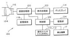
図1は実施例1の撮像装置の斜視図、図2は実施例1の撮像装置の構成を示すブロック図である。
図1に示すように、本実施例の撮像装置100はデジタルスチルカメラであり、外装を構成するケース102を有している。
ケース102の右側部にはレンズ鏡筒1A(図3)が組み込まれ、ケース102の前面右側部寄りの箇所に鏡筒1が位置している。
ケース102の前面上部寄りの箇所には閃光を発光するフラッシュ部106、光学式ファインダ107(図3)の対物レンズ108などが設けられている。
ケース102の上端面にはシャッタボタン110が設けられ、ケース102の後面には、前記光学式ファインダの接眼窓(不図示)、電源のオンオフ、撮影モード、再生モードの切替など種々の操作を行なうための複数の操作スイッチ112、撮像した映像を表示するディスプレイ114(図2)などが設けられている。Next, Embodiment 1 of the present invention will be described with reference to the drawings.
FIG. 1 is a perspective view of the imaging apparatus according to the first embodiment, and FIG. 2 is a block diagram illustrating a configuration of the imaging apparatus according to the first embodiment.
As shown in FIG. 1, the
A lens barrel 1 </ b> A (FIG. 3) is incorporated in the right side portion of the
A
A
図2に示すように、撮像装置100は、撮影光学系104によって結像された被写体像を撮像する鏡筒1の後端部分に配設されたCCDやCMOSセンサなどで構成された撮像素子116、該撮像素子116から出力された撮像信号に基づいて画像データを生成し、メモリカードなどの記憶媒体118に記録する画像処理部120、前記画像データをディスプレイ114に表示させる表示処理部122、後述するレンズ駆動機構10の駆動制御を行う駆動部124、レンズ駆動機構10の一部を構成するモータの回転量、回転方向を検出する検出機構17、操作スイッチ112やシャッタボタン110の操作に応じて画像処理部120、表示処理部122、駆動部124を制御するCPUなどを含む制御部126などを備えている。 As shown in FIG. 2, the
次に、レンズ鏡筒1Aの概略構成について説明する。
図3はレンズ鏡筒1Aの外観図、図4は鏡筒1の状態を説明する斜視図で、(a)が不使用時のレンズ収納状態すなわち沈胴状態を示すもの、(b)が広角状態、(c)が望遠状態を示すものである。図5は鏡筒1の断面図であり、(a)が沈胴状態、(b)が広角状態、(c)が望遠状態を示すものである。図6は鏡筒1の分解斜視図である。Next, a schematic configuration of the lens barrel 1A will be described.
3 is an external view of the lens barrel 1A, FIG. 4 is a perspective view for explaining the state of the lens barrel 1. FIG. 3A is a lens storage state when not in use, that is, a retracted state, and FIG. , (C) shows the telephoto state. 5A and 5B are cross-sectional views of the lens barrel 1, in which FIG. 5A shows a retracted state, FIG. 5B shows a wide-angle state, and FIG. 5C shows a telephoto state. FIG. 6 is an exploded perspective view of the lens barrel 1.
図3に示すように、レンズ鏡筒1Aは、ケース102に固定されるベース8と、撮影光学系104を収容保持する沈胴式の鏡筒1とを有している。
鏡筒1には、レンズをその光軸方向に移動可能に支持し回転駆動力が供給されることでレンズを光軸方向に移動させるレンズ移動機構が設けられ、ベース8には、レンズ移動機構に回転駆動力を供給するレンズ駆動機構10が設けられている。
鏡筒1はケース102の前面から前方に突出した使用位置(広角状態、望遠状態、および広角乃至望遠の中間状態)とケース102の前面に収容された収容位置(沈胴状態)との間を出没するように構成されている。As shown in FIG. 3, the lens barrel 1 </ b> A has a
The lens barrel 1 is provided with a lens moving mechanism that moves the lens in the optical axis direction by supporting the lens movably in the optical axis direction and is supplied with a rotational driving force, and the
The lens barrel 1 appears and disappears between the use position (wide angle state, telephoto state, and intermediate state between wide angle and telephoto) that protrudes forward from the front surface of the
図5に示すように、鏡筒1は光学的には3群構成である。すなわち、鏡筒1の光軸方向で被写体側を前方とし、前記光軸方向で撮像素子116側を後方としたとき、鏡筒1を構成する3群は、前方から後方に向かってこの順番で配設された1群、2群、3群によって構成されている。
鏡筒1は、1群と2群が所定のカムカーブに沿って光軸方向に駆動されることによってズーミングを行い、3群が光軸方向に微小に変位されることによってフォーカッシングを行う。すなわち、1群と2群の変位によって焦点距離を可変し、この焦点距離の変化によって生じた合焦位置のずれを3群の変位によって修正し適切に合焦させるように構成されている。As shown in FIG. 5, the lens barrel 1 has a three-group configuration optically. That is, when the subject side is the front in the optical axis direction of the barrel 1 and the
The lens barrel 1 performs zooming when the first group and the second group are driven in the optical axis direction along a predetermined cam curve, and performs focusing when the third group is slightly displaced in the optical axis direction. In other words, the focal length is varied by the displacement of the first group and the second group, and the shift of the in-focus position caused by the change of the focal length is corrected by the displacement of the third group and is appropriately focused.
図5、図6に示すように、1群レンズ枠2は、カム環4のカム溝4bに嵌合される3本(複数本)のカムピン2aと、1群を構成する複数のレンズを挿入・固定する複数のレンズ室2bと、収納時、沈胴状態においてレンズ前玉を保護するバリア機構部2cとを備えている。
2群レンズ枠3は、カム環4のカム溝4cに嵌合される3本(複数本)のカムピン3aと、2群を構成する複数のレンズを挿入、固定する複数のレンズ室3bとを備えている。また、2群レンズ枠3はアイリス・シャッター機構を構成してもよい。
カム環4は、カム環4を固定環6の内周部で回転駆動するためのギア部4aと、1群レンズ枠2のカムピン2aが嵌合される3本(複数本)のカム溝4bと、2群レンズ枠3のカムピン3aが嵌合される3本(複数本)のカム溝4cと、固定環6のカム溝6aに嵌合される3本(複数本)のカムピン4dとを備えている。本実施例では、ギア部4aにレンズ駆動機構10の回転駆動力が供給される。
カム溝4bおよびカム溝4cは、1群および2群を所定のカーブに沿って光軸方向に移動させ、ズーミング動作を行うものである。
直進案内環5は、カム環4と一体的に固定環6の内径で光軸方向に移動する部材で、1群レンズ枠2を光軸方向にガイドする案内溝5aと、2群レンズ枠3を光軸方向にガイドする案内溝5bとを備えている。
固定環6は、ベース8に固定される部材で、カム環4のカムピン4dが嵌合される3本(複数本)のカム溝6aを備えている。As shown in FIGS. 5 and 6, the first
The second
The
The
The
The fixed
3群レンズ枠7は3群を構成するレンズ71を挿入・固定するためのレンズ室を備えている。
可動レンズ72は、不図示の案内機構によってベース8に対して光軸方向に移動可能に保持されることで光軸方向に案内されており、不図示の駆動機構によって光軸方向に微小に変位されるように構成されている。なお、前記案内機構および駆動機構は本発明の要旨と直接関わらないためその説明を省略する。
ベース8には、固定環6が位置決め、固定される。
ベース8は、光学式ローパスカットフィルタや赤外カットフィルタなどの光学フィルタ11を挿入、位置決め、固定するための凹部と、鏡筒内部へのゴミなどの侵入を防止し、光学フィルタ11を弾性付勢するためのシールゴム12を挿入するための凹部とを備えている。
ベース8には撮像素子116が高精度に位置決め、固定される。The third
The movable lens 72 is guided in the optical axis direction by being held movably in the optical axis direction with respect to the
A fixed
The
The
なお、本実施例においては、1群レンズ枠2、2群レンズ枠3、カム環4、直進案内環5、固定環6によって特許請求の範囲のレンズ移動機構が構成されている。
また、本例において、1群レンズ枠2、2群レンズ枠3、カム環4、直進案内環5、固定環6、3群レンズ枠7、ベース8は、例えばガラス繊維を含有するポリカーボネート樹脂(黒色)などの繊維強化プラスチックで成形され、強度・遮光性と量産性を備えている。In this embodiment, the first
In this example, the first
鏡筒1のギア部4aに、レンズ駆動機構10の回転駆動力が供給されることで、鏡筒1の出没動作およびズーミング動作が行われる。
この鏡筒1の動作について説明する。
沈胴状態〜広角間の動作において、カム環4はギア部4aがレンズ駆動機構10によって駆動力を与えられることにより駆動されて、カムピン4dが固定環6のカム溝6aに沿って回転しながら光軸方向に被写体側に向けて移動する。このとき、直進案内環5はカム環4と一体的に移動する(図5中矢印A参照)。
このとき、1群レンズ枠2はカムピン2aがカム溝4bおよび案内溝5aに沿って所定のカーブによって移動する(図5中矢印B参照)。このとき、2群レンズ枠3はカムピン3aがカム溝4cおよび案内溝5bに沿って所定のカーブによって移動する(図5中矢印C参照)。以上により、1群および2群は所定の位置に移動し、光学的に広角の位置になる。When the rotational driving force of the
The operation of the lens barrel 1 will be described.
In the operation between the retracted state and the wide angle, the
At this time, in the first
広角〜望遠間の動作においても、カム環4はギア部4aがレンズ駆動機構10によって駆動力を与えられることにより駆動されるが、この範囲においてカム溝6aはカム環4が光軸方向に駆動しないように形成されており、直進案内環5も光軸方向に移動しない(図5中矢印D参照)。
このとき、1群レンズ枠2はカムピン2aがカム溝4bおよび案内溝5aに沿って所定のカーブによって移動する(図5中矢印E参照)。このとき、2群レンズ枠3はカムピン3aがカム溝4cおよび案内溝5bに沿って所定のカーブによって移動する(図3中矢印F参照)。以上により、1群および2群は所定のカーブに沿って移動し、光学的に広角〜望遠間を移動することによってズーミング動作を行う。Also in the operation between the wide angle and the telephoto, the
At this time, in the first
望遠→広角→沈胴状態については、レンズ駆動機構10を上記動作と反対向きに駆動することでカム環4を反対向きに回転させることによって行う。上記のレンズ駆動機構10によるカム環4の駆動によって鏡筒1は沈胴動作およびズーミング動作を行うが、これとは別に前記駆動機構によって可動レンズ72が光軸方向に微小に変位することによりフォーカッシング動作を行う(図5中矢印G参照)。 The telephoto-> wide-angle-> collapsed state is performed by rotating the
次に、レンズ駆動機構10の構成について詳細に説明する。
レンズ駆動機構10は、ギア部4aに回転駆動力を供給するものであり、レンズ駆動機構10は、モータ12、駆動ギア14と、ギア列16とを備えている。
検出機構17はモータ12の回転量、回転方向を検出するもので、検知板18、検出器20を含んで構成されている。
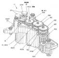
図3、図7に示すように、ベース8の右側部にホルダ22が取着され、このホルダ22にモータ12、駆動ギア14、ギア列16、検知板18、検出器20が収容され、蓋板24により閉塞されている。
モータ12はホルダ2220に保持されたケース1202と、ケース1202の一端から突出する出力軸1204を有している。本実施例では、出力軸1204は鏡筒1の光軸と平行する方向、すなわち撮像装置100の前後方向に向けて配設されている。
駆動ギア14は、出力軸1204の長手方向の中間部に固定され、検知板18は出力軸1204の先端(前端)に固定されている。
検知板18は本実施例では周方向に間隔をおいた3枚の羽根板により構成されている。
検出器20は、検知光を出射する投光部と前記検知光を受光する受光部とからなり、これら投光部と受光部との間に検知板18が位置するように配設されている。本実施例では検出器20は2つ設けられ、それぞれホルダ22に取着されている。モータ12の駆動により出力軸1204が回転され、検知板20が検出器20の投光部と受光部の間を通過することにより検出器20は検知板18の各羽根板の移動に対応して検知信号を生成する。制御部126は前記検知信号に基づいてモータ12の回転量、回転方向を検出しその検出結果に基づいて駆動部124を介してモータ12の回転制御を行う。Next, the configuration of the
The
The
As shown in FIGS. 3 and 7, a
The
The
In this embodiment, the
The
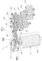
前記ギア列16は、モータ12の回転駆動力をカム環4のギア部4aに伝達するもので、駆動ギア14に噛合する第1ギア16Aと、ギア部4aに噛合する最終ギア16Hと、これら第1ギア16Aと最終ギア16Hとの間を連結するギア群1601とで構成されている。
より詳細に説明すると、第1ギア16Aは、ホルダ22により片持ち支持された支軸1602上で回転可能に配設されている。
本実施例では、図8乃至図11に示すように、第1ギア16Aの前方に検知板18が位置しており、検知板18の外周部は、支軸1602の前方に臨んでいる。言い換えると、出力軸1204の長手方向から見て検知板18の輪郭と第1ギア16Aの輪郭は一部重複しており、また、検知板18の輪郭は第1ギア16Aの軸芯と重複している。より詳細に説明すると、第1ギア16Aの前方に検知板18の移動軌跡が位置しており、検知板18の移動軌跡の外周部は、支軸1602の前方に臨んでいる。言い換えると、出力軸1204の長手方向から見て検知板18の移動軌跡は第1ギア16Aの輪郭と一部重複しており、また、検知板18の移動軌跡は第1ギア16Aの軸芯と重複している。The
More specifically, the
In the present embodiment, as shown in FIGS. 8 to 11, the
最終ギア16Hは、ホルダ22と蓋板24により両持ち支持された支軸1608上で回転可能に支持されている。
第1ギア16Aの支軸1602と最終ギア16Hの支軸1608との間に、2本の支軸1604、1606が配設され、最終ギア16Hの支軸1608と2本の支軸1604,1606との合計3本の支軸1608,1604,1606がそれぞれホルダ22と蓋板24により両持ち支持され、前記ギア群1601はこれら2本の支軸1604,1606上に配設されている。
より詳細に説明すると、2本の支軸1604,1606のうち、第1ギア16Aの支軸寄りに位置する支軸1604には、第2ギア16B、第3ギア16C、第4ギア16Dが回転可能に配設されている。
また、2本の支軸1604,1606のうち、最終ギア16Hの支軸1608寄りに位置する支軸1606には、第5ギア16E、第6ギア16F、第7ギア16Gが回転可能に配設されている。
そして、第1ギア16Aに第2ギア16Bの大径歯部が噛合し、第2ギア16Bの小径歯部に第5ギア16Eの大径歯部が噛合し、第5ギア16Eの小径歯部に第3ギア16Cの大径歯部が噛合し、第3ギア16Cの小径歯部に第6ギア16Fの大径歯部が噛合し、第6ギア16Fの小径歯部に第4ギア16Dの大径歯部が噛合し、第4ギア16Dの小径歯部に第7ギア16Gの大径歯部が噛合し、第7ギア16Gの小径歯部に最終ギア16Hが噛合しており、モータ12の回転駆動力は第1ギア16Aからこれら第1乃至第7ギア16G、最終ギア16Hを経てギア部4aに伝達され、本実施例ではモータ12の回転速度が7段で減速されている。
なお、ギア列16におけるギア比は、沈胴→広角→望遠および望遠→広角→沈胴の範囲において十分な駆動力を得られるように選定される。The
Two
More specifically, the second gear 16B, the
The
Then, the large-diameter tooth portion of the second gear 16B meshes with the
The gear ratio in the
なお、駆動ギア14と第1ギア16Aとの間で生じる動作時の雑音を低減する上で、第1ギア16Aの転位係数はマイナスの値であって−0.3以下とすることが好ましく、より好ましくは−0.05以下−0.2以上が好ましく、さらに好ましくは−0.08以下−0.1以上が好ましい。
また、第1ギア16Aの転位係数をマイナスの値にすると強度が低下するが、第1ギア16Aは駆動ギア14に噛合する初段のギアであるため第1ギア16Aに掛かる負荷が少ないため問題は生じない。In order to reduce the noise during operation between the
Further, when the shift coefficient of the
本実施例では、ホルダ22は合成樹脂製でモールド成型されている。
また、モータ12の回転駆動時、第1ギア16Aの支軸1602に作用する負荷は小さく、そのため、第1ギア16Aの支軸1602も合成樹脂製でモールド成型されている。
また、モータ12の回転時、3本の支軸1608,1604,1606に作用する負荷は支軸1602に比べて大きく、そのため、3本の支軸1608,1604,1606は金属製でホルダ22と蓋板24により両持ち支持されている。In the present embodiment, the
Further, when the
In addition, the load acting on the three
本実施例によれば、モータ12の出力軸1204に検知板18を取り付け、出力軸1204の駆動ギア14に噛合する第1ギア16Aを片持ち式にホルダ22で支持するようにしたので、駆動ギア14の前方スペースを利用して検知板18を配設でき、従来構造のように駆動ギア14と反対側に位置するモータ12のケースの箇所に検知板18配設用の専用スペースを確保する必要はなく、検知板18を配設するにあたり検知板18の占有スペースを最小限に抑えることができ小型化を図る上で有利となる。
また、従来構造のようにモータ12の回転を検出するために専用の回転検出用ギアを設ける必要はなく、したがって、部品点数の削減化を図る上でも有利となる。
また、検知板18を、出力軸1204の長手方向から見て、検知板18の輪郭と第1ギア16Aとが一部重複するように配設すると、言い換えると、検知板18の移動軌跡の輪郭と第1ギア16Aの輪郭とが一部重複するように配設すると、検知板18を配設するにあたり検知板18の占有スペースを最小限に抑える上でより一層有利となり、小型化を図る上でより一層有利となる。
さらに、実施例のように、出力軸1204の長手方向から見て、検知板18の輪郭と第1ギア16Aの軸心とを重複するように配設すると、言い換えると、検知板18の移動軌跡を第1ギア16Aの軸心と重複するように配設すると、検知板18の占有スペースを最小限に抑える上でより一層有利となり、小型化を図る上でより一層有利となる。
また、実施例では、第1ギア16Aにおいて、大径歯部をホルダ22側に位置させ小径歯部を蓋板24側に位置させ、かつ、第2ギア16Bにおいて、小径歯部をホルダ22側に位置させ大径歯部を蓋板24側に位置させ、第1ギア16Aの大径歯部を第2ギア16Bの小径歯部の径方向外側で大径歯部に臨ませて配置したので、言い換えると、支軸の長手方向から見て、第1ギア16Aの大径歯部の輪郭と第2ギア16Bの大径歯部の輪郭を一部重複して配設したので、支軸1602、1604方向のギア列16のコンパクト化が図られている。According to the present embodiment, the
Further, it is not necessary to provide a dedicated rotation detection gear for detecting the rotation of the
Further, when the
Further, as in the embodiment, when viewed from the longitudinal direction of the
In the embodiment, in the
なお、本実施例では、1群レンズ枠2、2群レンズ枠3、カム環4、直進案内環5、固定環6によってレンズ移動機構が構成されている場合について説明したが、レンズ移動機構は実施例の構成に限定されず、従来公知の様々な機構が採用可能である。
また、本実施例では、撮像装置としてデジタルスチルカメラを用いて説明したが、本発明は、ビデオカメラ、その他種々の撮像装置に適用可能である。In this embodiment, the case where the lens moving mechanism is configured by the first
In this embodiment, a digital still camera is used as the imaging device. However, the present invention can be applied to a video camera and other various imaging devices.
100……撮像装置、1……鏡筒、1A……レンズ鏡筒、8……ベース、10……レンズ駆動機構、12……モータ、1204……出力軸、14……駆動ギア、16……ギア列、16A……第1ギア、17……検出機構、18……検知板、20……検知器。
DESCRIPTION OF
Claims (4)
Translated fromJapanese前記鏡筒には、レンズをその光軸方向に移動可能に支持し回転駆動力が供給されることで前記レンズを光軸方向に移動させるレンズ移動機構が設けられ、
前記ベースには、前記レンズ移動機構に回転駆動力を供給するレンズ駆動機構が設けられ、
前記レンズ駆動機構は、出力軸を有するモータと、前記出力軸に設けられた駆動ギアと、前記駆動ギアに噛合し前記モータの動力を前記レンズ移動機構に供給するギア列とを有し、
さらに、前記モータの回転量を検出する検出機構が設けられたレンズ鏡筒であって、
前記出力軸は前記モータのケースの一端から突出して設けられ、
前記検出機構は、前記出力軸の先端に固定され該出力軸と一体に回転する検知板と、前記検知板の回転を検出する検出器を含んで構成され、
前記駆動ギアは前記出力軸の長手方向の中間部に固定され、
前記ギア列は、前記ベースに取着され合成樹脂によりモールド成型されたホルダの内部に収容され、
前記ホルダの内部は該ホルダに取着された蓋板により閉塞され、
前記ギア列は、第1ギアと第2ギアとを含んで構成され、
前記第1ギアは小径歯部と大径歯部を有し、
前記第2ギアは小径歯部と大径歯部を有し、
前記第1ギアは、前記ホルダで片持ち支持された支軸上で回転可能に配設され、
前記第1ギアは、前記検知板と前記ケースとの間であって、該検知板側に前記小径歯部を向け、前記大径歯部が前記駆動ギアに歯合するように配設され、
前記支軸は合成樹脂製で前記ホルダと一体にモールド成型されるとともに、該支軸はその先端面が前記第1ギアが前記検知板に臨む面と略面一に構成され、
前記モータの出力軸の長手方向から見て、前記検知板の輪郭内に前記第1ギアの軸心が位置し、
前記第2ギアは、該第2ギアの前記大径歯部を前記第1ギアの前記小径歯部に歯合して、前記大径歯部を前記検知板側に向けて配設され、
前記第1ギアの大径歯部と前記第2ギアの大径歯部との隙間は、前記第1ギアの前記検知板側の面と該検知板との隙間よりも小さい、
ことを特徴とするレンズ鏡筒。A base and a lens barrel provided on the base;
The lens barrel is provided with a lens moving mechanism for moving the lens in the optical axis direction by supporting the lens movably in the optical axis direction and supplying a rotational driving force.
The base is provided with a lens driving mechanism for supplying a rotational driving force to the lens moving mechanism,
The lens drive mechanism includes a motor having an output shaft, a drive gear provided on the output shaft, and a gear train that meshes with the drive gear and supplies power of the motor to the lens moving mechanism.
Furthermore, a lens barrel provided with a detection mechanism for detecting the amount of rotation of the motor,
The output shaft is provided to protrude from one end of the motor case,
The detection mechanism includes a detection plate that is fixed to a tip of the output shaft and rotates integrally with the output shaft, and a detector that detects rotation of the detection plate,
The drive gear is fixed to an intermediate portion in the longitudinal direction of the output shaft,
The gear train is accommodated in a holder that is attached to the base and molded by a synthetic resin,
The inside of the holder is closed by a cover plate attached to the holder,
The gear train includes a first gear and a second gear,
The first gear has a small diameter tooth portion and a large diameter tooth portion,
The second gear has a small diameter tooth portion and a large diameter tooth portion,
The first gear is rotatably arranged on a spindle that is cantilevered by the holder,
The first gear is disposed between the detection plate and the case, with the small-diameter tooth portion facing the detection plate side, and the large-diameter tooth portion meshing with the drive gear,
The support shaft is made of synthetic resin and is molded integrally with the holder, and the support shaft is configured so that a tip surface thereof is substantially flush with a surface where the first gear faces the detection plate,
When viewed from the longitudinal direction of the output shaft of the motor, the axis of the first gear is located within the contour of the detection plate,
The second gear is disposed with the large-diameter tooth portion of the second gear meshing with the small-diameter tooth portion of the first gear and the large-diameter tooth portion facing the detection plate side,
The gap between the large-diameter tooth portion of the first gear and the large-diameter tooth portion of the second gear is smaller than the gap between the surface on the detection plate side of the first gear and the detection plate.
A lens barrel characterized by that.
前記レンズ鏡筒は、ベースと、前記ベースに設けられた鏡筒とを有し、
前記鏡筒には、前記レンズをその光軸方向に移動可能に支持し回転駆動力が供給されることで前記レンズを光軸方向に移動させるレンズ移動機構が設けられ、
前記ベースには、前記レンズ移動機構に回転駆動力を供給するレンズ駆動機構が設けられ、
前記レンズ駆動機構は、出力軸を有するモータと、前記出力軸に設けられた駆動ギアと、前記駆動ギアに噛合し前記モータの動力を前記レンズ移動機構に供給するギア列とを有し、
さらに、前記モータの回転量を検出する検出機構が設けられた撮像装置であって、
前記出力軸は前記モータのケースの一端から突出して設けられ、
前記検出機構は、前記出力軸の先端に固定され該出力軸と一体に回転する検知板と、前記検知板の回転を検出する検出器を含んで構成され、
前記駆動ギアは前記出力軸の長手方向の中間部に固定され、
前記ギア列は、前記ベースに取着され合成樹脂によりモールド成型されたホルダの内部に収容され、
前記ホルダの内部は該ホルダに取着された蓋板により閉塞され、
前記ギア列は、第1ギアと第2ギアとを含んで構成され、
前記第1ギアは小径歯部と大径歯部を有し、
前記第2ギアは小径歯部と大径歯部を有し、
前記第1ギアは、前記ホルダで片持ち支持された支軸上で回転可能に配設され、
前記第1ギアは、前記検知板と前記ケースとの間であって、該検知板側に前記小径歯部を向け、前記大径歯部が前記駆動ギアに歯合するように配設され、
前記支軸は合成樹脂製で前記ホルダと一体にモールド成型されるとともに、該支軸はその先端面が前記第1ギアが前記検知板に臨む面と略面一に構成され、
前記モータの出力軸の長手方向から見て、前記検知板の輪郭内に前記第1ギアの軸心が位置し、
前記第2ギアは、該第2ギアの前記大径歯部を前記第1ギアの前記小径歯部に歯合して、前記大径歯部を前記検知板側に向けて配設され、
前記第1ギアの大径歯部と前記第2ギアの大径歯部との隙間は、前記第1ギアの前記検知板側の面と該検知板との隙間よりも小さい、
ことを特徴とする撮像装置。A lens barrel having a lens, and an image sensor that captures a subject image guided by the lens;
The lens barrel has a base and a barrel provided on the base,
The lens barrel is provided with a lens moving mechanism for supporting the lens movably in the optical axis direction and moving the lens in the optical axis direction by being supplied with a rotational driving force.
The base is provided with a lens driving mechanism for supplying a rotational driving force to the lens moving mechanism,
The lens drive mechanism includes a motor having an output shaft, a drive gear provided on the output shaft, and a gear train that meshes with the drive gear and supplies power of the motor to the lens moving mechanism.
Furthermore, an imaging apparatus provided with a detection mechanism for detecting the amount of rotation of the motor,
The output shaft is provided to protrude from one end of the motor case,
The detection mechanism includes a detection plate that is fixed to a tip of the output shaft and rotates integrally with the output shaft, and a detector that detects rotation of the detection plate,
The drive gear is fixed to an intermediate portion in the longitudinal direction of the output shaft,
The gear train is accommodated in a holder that is attached to the base and molded by a synthetic resin,
The inside of the holder is closed by a cover plate attached to the holder,
The gear train includes a first gear and a second gear,
The first gear has a small diameter tooth portion and a large diameter tooth portion,
The second gear has a small diameter tooth portion and a large diameter tooth portion,
The first gear is rotatably arranged on a spindle that is cantilevered by the holder,
The first gear is disposed between the detection plate and the case, with the small-diameter tooth portion facing the detection plate side, and the large-diameter tooth portion meshing with the drive gear,
The support shaft is made of synthetic resin and is molded integrally with the holder, and the support shaft is configured so that a tip surface thereof is substantially flush with a surface where the first gear faces the detection plate,
When viewed from the longitudinal direction of the output shaft of the motor, the axis of the first gear is located within the contour of the detection plate,
The second gear is disposed with the large-diameter tooth portion of the second gear meshing with the small-diameter tooth portion of the first gear and the large-diameter tooth portion facing the detection plate side,
The gap between the large-diameter tooth portion of the first gear and the large-diameter tooth portion of the second gear is smaller than the gap between the surface on the detection plate side of the first gear and the detection plate.
An imaging apparatus characterized by that.
Priority Applications (4)
| Application Number | Priority Date | Filing Date | Title |
|---|---|---|---|
| JP2004114393AJP4096262B2 (en) | 2004-04-08 | 2004-04-08 | Lens barrel and imaging device |
| US11/092,895US7228068B2 (en) | 2004-04-08 | 2005-03-30 | Lens barrel structure and image capture apparatus |
| KR1020050029045AKR101180892B1 (en) | 2004-04-08 | 2005-04-07 | Lens barrel structure and image capture apparatus |
| CNB2005100648763ACN100362383C (en) | 2004-04-08 | 2005-04-08 | Lens barrel structure and image capture device |
Applications Claiming Priority (1)
| Application Number | Priority Date | Filing Date | Title |
|---|---|---|---|
| JP2004114393AJP4096262B2 (en) | 2004-04-08 | 2004-04-08 | Lens barrel and imaging device |
Publications (2)
| Publication Number | Publication Date |
|---|---|
| JP2005300760A JP2005300760A (en) | 2005-10-27 |
| JP4096262B2true JP4096262B2 (en) | 2008-06-04 |
Family
ID=35136525
Family Applications (1)
| Application Number | Title | Priority Date | Filing Date |
|---|---|---|---|
| JP2004114393AExpired - LifetimeJP4096262B2 (en) | 2004-04-08 | 2004-04-08 | Lens barrel and imaging device |
Country Status (4)
| Country | Link |
|---|---|
| US (1) | US7228068B2 (en) |
| JP (1) | JP4096262B2 (en) |
| KR (1) | KR101180892B1 (en) |
| CN (1) | CN100362383C (en) |
Families Citing this family (6)
| Publication number | Priority date | Publication date | Assignee | Title |
|---|---|---|---|---|
| JP4732044B2 (en)* | 2005-07-19 | 2011-07-27 | キヤノン株式会社 | Lens barrel and imaging device |
| DE102008033383A1 (en)* | 2008-07-16 | 2010-01-21 | Osram Gesellschaft mit beschränkter Haftung | Mounting frame for an optical element |
| US8807847B2 (en)* | 2011-02-09 | 2014-08-19 | Panasonic Corporation | Lens barrel and imaging device |
| US8861104B2 (en) | 2011-02-09 | 2014-10-14 | Panasonic Corporation | Lens barrel and imaging device |
| DE102015108762A1 (en)* | 2015-06-03 | 2016-12-08 | Valeo Schalter Und Sensoren Gmbh | Holding device for holding a drive unit of a Umlenkspiegelanordnung, detection device with a Umlenkspiegelanordnung and motor vehicle |
| WO2020110910A1 (en)* | 2018-11-30 | 2020-06-04 | キヤノン電子株式会社 | Lens drive actuator and mobile terminal |
Family Cites Families (5)
| Publication number | Priority date | Publication date | Assignee | Title |
|---|---|---|---|---|
| JP3827260B2 (en)* | 1996-09-04 | 2006-09-27 | 富士写真フイルム株式会社 | Zoom lens device |
| JP2001194574A (en) | 2000-01-11 | 2001-07-19 | Fuji Photo Film Co Ltd | Moving mechanism, lens barrel and image pickup device |
| JP2002182285A (en)* | 2000-12-11 | 2002-06-26 | Fuji Photo Optical Co Ltd | Camera |
| JP2002318338A (en) | 2001-04-23 | 2002-10-31 | Olympus Optical Co Ltd | Motor-driven zoom camera |
| JP2004127372A (en)* | 2002-09-30 | 2004-04-22 | Fuji Photo Film Co Ltd | Disk cartridge |
- 2004
- 2004-04-08JPJP2004114393Apatent/JP4096262B2/ennot_activeExpired - Lifetime
- 2005
- 2005-03-30USUS11/092,895patent/US7228068B2/ennot_activeExpired - Fee Related
- 2005-04-07KRKR1020050029045Apatent/KR101180892B1/ennot_activeExpired - Fee Related
- 2005-04-08CNCNB2005100648763Apatent/CN100362383C/ennot_activeExpired - Fee Related
Also Published As
| Publication number | Publication date |
|---|---|
| JP2005300760A (en) | 2005-10-27 |
| US20050238342A1 (en) | 2005-10-27 |
| CN1707303A (en) | 2005-12-14 |
| CN100362383C (en) | 2008-01-16 |
| US7228068B2 (en) | 2007-06-05 |
| KR101180892B1 (en) | 2012-09-07 |
| KR20060045577A (en) | 2006-05-17 |
Similar Documents
| Publication | Publication Date | Title |
|---|---|---|
| JP4635550B2 (en) | camera | |
| JP5006602B2 (en) | Imaging device | |
| US8493667B2 (en) | Lens apparatus and imaging apparatus | |
| JP4760293B2 (en) | Lens barrel cam mechanism | |
| JP4724294B2 (en) | Lens barrel and method of assembling lens barrel | |
| JP4193748B2 (en) | Retractable lens barrel and imaging device | |
| JP4250946B2 (en) | Optical unit and imaging apparatus | |
| JP3944785B2 (en) | Retractable lens barrel and imaging device | |
| JP2007248642A (en) | Lens barrel and imaging device | |
| JP4096262B2 (en) | Lens barrel and imaging device | |
| JP2006058769A (en) | Collapsible mount type lens barrel and imaging apparatus | |
| JP4471371B2 (en) | Lens barrel and optical device | |
| JP4595783B2 (en) | Lens barrel | |
| JP4420597B2 (en) | Imaging device | |
| JP5056971B2 (en) | Lens barrel cam mechanism | |
| JP4218308B2 (en) | Optical unit and imaging apparatus | |
| JP2003227989A (en) | Zoom lens barrel, lens barrel and camera | |
| EP2203773B1 (en) | Lens apparatus and imaging apparatus | |
| JP5397774B2 (en) | Lens barrel, imaging device, and electronic device | |
| JP2008151938A (en) | Lens barrel and imaging device | |
| JP2011033847A (en) | Lens device and photographing apparatus | |
| JP4362706B2 (en) | Lens barrel and imaging device | |
| JP2009180811A (en) | Lens barrel and imaging device | |
| JP2005049783A (en) | Imaging device and lens device | |
| JP2009116369A5 (en) |
Legal Events
| Date | Code | Title | Description |
|---|---|---|---|
| A977 | Report on retrieval | Free format text:JAPANESE INTERMEDIATE CODE: A971007 Effective date:20070116 | |
| A131 | Notification of reasons for refusal | Free format text:JAPANESE INTERMEDIATE CODE: A131 Effective date:20070821 | |
| A521 | Request for written amendment filed | Free format text:JAPANESE INTERMEDIATE CODE: A523 Effective date:20071022 | |
| TRDD | Decision of grant or rejection written | ||
| A01 | Written decision to grant a patent or to grant a registration (utility model) | Free format text:JAPANESE INTERMEDIATE CODE: A01 Effective date:20080214 | |
| A61 | First payment of annual fees (during grant procedure) | Free format text:JAPANESE INTERMEDIATE CODE: A61 Effective date:20080227 | |
| FPAY | Renewal fee payment (event date is renewal date of database) | Free format text:PAYMENT UNTIL: 20110321 Year of fee payment:3 | |
| FPAY | Renewal fee payment (event date is renewal date of database) | Free format text:PAYMENT UNTIL: 20120321 Year of fee payment:4 | |
| FPAY | Renewal fee payment (event date is renewal date of database) | Free format text:PAYMENT UNTIL: 20130321 Year of fee payment:5 |