JP4096143B2 - Lighting control device - Google Patents
Lighting control deviceDownload PDFInfo
- Publication number
- JP4096143B2 JP4096143B2JP36551699AJP36551699AJP4096143B2JP 4096143 B2JP4096143 B2JP 4096143B2JP 36551699 AJP36551699 AJP 36551699AJP 36551699 AJP36551699 AJP 36551699AJP 4096143 B2JP4096143 B2JP 4096143B2
- Authority
- JP
- Japan
- Prior art keywords
- value
- illuminance
- target
- illuminance value
- luminaire
- Prior art date
- Legal status (The legal status is an assumption and is not a legal conclusion. Google has not performed a legal analysis and makes no representation as to the accuracy of the status listed.)
- Expired - Lifetime
Links
Images

Classifications
- Y—GENERAL TAGGING OF NEW TECHNOLOGICAL DEVELOPMENTS; GENERAL TAGGING OF CROSS-SECTIONAL TECHNOLOGIES SPANNING OVER SEVERAL SECTIONS OF THE IPC; TECHNICAL SUBJECTS COVERED BY FORMER USPC CROSS-REFERENCE ART COLLECTIONS [XRACs] AND DIGESTS
- Y02—TECHNOLOGIES OR APPLICATIONS FOR MITIGATION OR ADAPTATION AGAINST CLIMATE CHANGE
- Y02B—CLIMATE CHANGE MITIGATION TECHNOLOGIES RELATED TO BUILDINGS, e.g. HOUSING, HOUSE APPLIANCES OR RELATED END-USER APPLICATIONS
- Y02B20/00—Energy efficient lighting technologies, e.g. halogen lamps or gas discharge lamps
- Y02B20/40—Control techniques providing energy savings, e.g. smart controller or presence detection
Landscapes
- Circuit Arrangement For Electric Light Sources In General (AREA)
Description
Translated fromJapanese【0001】
【発明の属する技術分野】
本発明は、照度センサに従い調光制御する照明制御装置に関する。
【0002】
【従来の技術】
従来、この種の照明制御装置としては、たとえば図3に示す構成が知られている。
【0003】
図3は設置状態を示す説明図で、この図3に示すように、1は床面で、この床面1から所定距離を介した上方には床面1とほぼ平行な天井2が設けられている。また、天井2には蛍光ランプなどを有する照明器具3およびこの照明器具3の照射領域の明るさを検知する照度センサ4とが配設されている。そして、照度センサ4に照明制御装置5が接続され、この照明制御装置5は照明器具3に接続されている。
【0004】
そして、一般に、照度センサ4で検知される天井2の近傍の照度値は、照明器具3以外からの光束がない場合には、照明器具3から発する光束Φが床面に到達し、床面1から反射係数κで反射した光束が天井2に到達した単位面積当たりの光束で求められる。
【0005】
したがって、天井2に照度センサ4を配置した場合、測定しようとする床面照度値は反射係数κによって変化する。このため、照度センサ4とは別個の照度計を用いて床面照度値を検出し、床面照度値を検出する照度計と照度センサ4との照度値の違いから床面の反射係数κを算出し、この反射係数κを用いて照明器具3の明るさを設定している。
【0006】
また、このように反射係数κを計算により算出しない場合には、照度計を用いて照度センサをスケーリングして反射係数κを求めて、同様に照明器具3の明るさを設定している。
【0007】
【発明が解決しようとする課題】
従来のように照明制御装置を設定する際には、照度計を用いて照度センサで得られた照度値を実際の照度値に校正しなければならず、設定が煩雑になる問題を有している。
【0008】
本発明は、上記問題点に鑑みなされたもので、簡単に照度値を設定できる照明制御装置を提供することを目的とする。
【0009】
【課題を解決するための手段】
請求項1記載の照明制御装置は、光源を有する照明器具と;照明器具が照射する被照射領域の照度値を検知する照度センサと;設計時に予め決定した被照射領域の設計照度値を照明器具の寿命末期時に対応する光束と消灯状態との照度値の差分で除することで求めた校正用の係数により被照射領域の目標照度値を除して、この目標照度値に対応する目標値を得る設定手段と;この設定手段で得た目標値が照度センサで検出した実際の検出値より低くない場合には照明器具の光源の明るさを増加させ、設定手段で得た目標値が照度センサで検出した実際の検出値より低い場合には照明器具の光源の明るさを減少させる制御手段と;を具備するもので、照明器具を取り付ける際には予め設定状況をシミュレーションを設定して目的照度値を計算して設計していることが多いため、照度センサで検知されている照射領域の照度値を予め設定されている照射領域の目標照度値であるとしても大きく数値が異なることがないので、設計時に予め決定した被照射領域の設計照度値を照明器具の寿命末期時に対応する光束と消灯状態との照度値の差分で除することで求めた校正用の係数により被照射領域の目標照度値を除して、この目標照度値に対応する目標値を得て、この目標値が照度センサで検出した実際の検出値より低くない場合には照明器具の光源の明るさを増加させ、設定手段で得た目標値が照度センサで検出した実際の検出値より低い場合には照明器具の光源の明るさを減少させることにより、設置の際に別個照度計などが不要になり、簡単に設定可能であるとともに、たとえば蛍光ランプを用いる場合には寿命末期には初期光束に比べて光束が大きく低下するが、寿命末期時にでも必要照度値が得られるようにする。
【0010】
請求項2記載の照明制御装置は、請求項1記載の照明制御装置において、校正用の係数を変更することにより目標照度値を任意に変更できる設定可変手段を具備しているもので、任意の目標照度値を設定可能である。
【0011】
【発明の実施の形態】
以下、本発明の照明制御装置の一実施の形態を図面を参照して説明する。
【0012】
また、図3で示す従来例と同様に、床面1から所定距離を介した上方には床面1とほぼ平行な天井2が設けられている。また、天井2には光源として蛍光ランプなどを有する照明器具3およびこの照明器具3の照射領域の明るさを検知する照度センサ4とが配設されている。そして、照度センサ4に照明制御装置5が接続され、この照明制御装置5は照明器具3に接続されている。なお、照明制御装置5は、目標照度値を設定する設定可変手段を有している。
【0013】
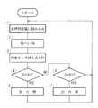
そして、たとえば出力電圧で表される照度値を制御する場合には、図2に示すように、まず、照明制御装置5に設定しようとする照射領域の目標照度値L1を読み込ませ(ステップ1)、目標照度値L1を床面1の目標照度値L1と照度センサ4で検出される照度値との関係を示す校正用の係数mで除して照度センサ4の出力電圧となる目標値Epを算出し(ステップ2)、照度センサ4の出力電圧である床面1の実際の照度値Enを読み取る(ステップ3)。そして、目標値Epが実際の照度値Enより高いか否かを判断し(ステップ4)、高い場合には照明制御装置5により照明器具3の出力を増加して光束を増加する調光をし(ステップ5)、ステップ1に戻り、一方、ステップ4で高くないと判断されると、目標値Epが実際の照度値Enより低いか否かを判断し(ステップ6)、低い場合には照明制御装置5により照明器具3の出力を減少して光束を減少する調光をし(ステップ7)、ステップ1に戻る。
【0014】
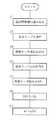
ここで、床面1の目標照度値L1と照度センサ4との関係を示す係数mの算出について図1に示すフローチャートを参照して説明する。
【0015】
まず、設計により求められた目標照度値L1を読み込む(ステップ11)。また、外光あるいは図示しない他の照明器具からの照明によりオフセットが生じていることがあるので、照明器具3の蛍光ランプを消灯し(ステップ12)、この蛍光ランプが消灯している場合の照度センサ4の出力電圧の照度値E0を初期値として読み込む(ステップ13)。
【0016】
次に、一般に蛍光ランプの寿命末期の光束、すなわち光束維持率は初期光束の0.7ないし0.75程度であるので、設定可変手段では蛍光ランプの寿命末期時にも目標照度値L1を確保できるように蛍光ランプを70%程度の出力で点灯させ(ステップ14)、蛍光ランプの点灯時の照度値E1を読み込む(ステップ15)。
【0017】
そして、蛍光ランプが点灯したことによる照度値の増加を照度値E1から照度値E0を減じて求め(ステップ16)、蛍光ランプが点灯したことによる照度値E1の設計時に予め決定した設計照度値L0に対する係数mを求める(ステップ17)。
【0018】
このように求めた係数mをステップ2に代入して用いることにより、たとえば床面1の設計照度値である目標照度値L1が1000lxであったとすると実際の照度値が1000lxでなかったとしても1000lxとみなして制御することにより、実際に測定することなく、実際の照度値Enを目標照度値L1に対応する目標値Epとして蛍光ランプを調光でき、従来のように別個の照度計が不要になり、設置作業が容易になる。なお、このように実際の照度値Enを目標照度値L1に対する目標値Epとして設定も、目標照度値L1は実際には照明器具3の形式、配置および数量などは予めわかっており、シミュレーションで正確に算出でき、設計照度値L0として求めることができるため、実際の使用にも大きな差が生ずることなく取り扱え、目標値Epとしても問題がない。
【0019】
また、照明制御装置5は設定可変手段を有し、この設定可変手段により係数mを変更することにより、任意の目標照度値で制御できる。
【0020】
【発明の効果】
請求項1記載の照明制御装置によれば、照明器具を取り付ける際には予め設定状況をシミュレーションを設定して目的照度値を計算して設計していることが多いため、照度センサで検知されている照射領域の照度値を予め設定されている照射領域の目標照度値であるとしても大きく数値が異なることがないので、照度センサで検知された照度値を照明器具の寿命末期時に対応する光束と消灯状態との照度値の差分で除することで求めた校正用の係数により被照射領域の目標照度値を除して、この目標照度値に対応する目標値を得て、この目標値が照度センサで検出した実際の検出値より低くない場合には照明器具の光源の明るさを増加させ、設定手段で得た目標値が照度センサで検出した実際の検出値より低い場合には照明器具の光源の明るさを減少させることにより、設置の際に別個照度計などが不要になり、簡単に設定可能にできるとともに、設定可変手段は照明器具の初期光束に対する寿命末期時の明るさの割合で目標照度を設定できるので、たとえば蛍光ランプを用いる場合には寿命末期には初期光束に比べて光束が大きく低下するが、寿命末期時にでも必要照度値を得ることができる。
【0021】
請求項2記載の照明制御装置によれば、請求項1記載の照明制御装置に加え、予め設定されている照射領域の目標照度値を、校正用の係数を変更することにより設定可変手段で任意に設定可能であるので、任意の目標照度値を設定できる。
【図面の簡単な説明】
【図1】 本発明の照明制御装置の一実施の形態の設定動作を示すフローチャートである。
【図2】 同上動作を示すフローチャートである。
【図3】 一般的な設置状態を示す説明図である。
【符号の説明】
3 照明器具
4 照度センサ
5 照明制御装置
En,E0,E1 照度値
L0 設計照度値
L1 目標照度値[0001]
BACKGROUND OF THE INVENTION
The present invention relates to an illumination control device that performs dimming control according to an illuminance sensor.
[0002]
[Prior art]
Conventionally, as this type of illumination control device, for example, a configuration shown in FIG. 3 is known.
[0003]
FIG. 3 is an explanatory diagram showing the installation state. As shown in FIG. 3, 1 is a floor surface, and a
[0004]
In general, the illuminance value in the vicinity of the
[0005]
Therefore, when the
[0006]
When the reflection coefficient κ is not calculated by calculation, the illuminance sensor is scaled using an illuminometer to obtain the reflection coefficient κ, and the brightness of the
[0007]
[Problems to be solved by the invention]
When setting the illumination control device as in the past, the illuminance value obtained by the illuminance sensor using an illuminometer must becalibrated to the actual illuminance value, and there is a problem that the setting becomes complicated Yes.
[0008]
The present invention has been made in view of the above problems, and an object thereof is to provide an illumination control device that can easily set an illuminance value.
[0009]
[Means for Solving the Problems]
The illumination control device according to
[0010]
Lighting control apparatus as claimed in
[0011]
DETAILED DESCRIPTION OF THE INVENTION
Hereinafter, an embodiment of a lighting control device of the present invention will be described with reference to the drawings.
[0012]
Similarly to the conventional example shown in FIG. 3, a
[0013]
For example, when controlling the illuminance value represented by the output voltage, first, the target illuminance value L1 of the irradiation region to be set is read in the
[0014]
Here, calculation of the coefficient m indicating the relationship between the target illuminance value L1 of the
[0015]
First, the target illuminance value L1 obtained by design is read (step 11). Further, since there may be an offset due to external light or illumination from another lighting fixture (not shown), the fluorescent lamp of the
[0016]
Next, since the light flux at the end of life of the fluorescent lamp, that is, the light flux maintenance factor is generally about 0.7 to 0.75 of the initial light flux, the setting variable means can ensure the target illuminance value L1 even at the end of the life of the fluorescent lamp. Thus, the fluorescent lamp is turned on at an output of about 70% (step 14), and the illuminance value E1 when the fluorescent lamp is turned on is read (step 15).
[0017]
Then, an increase in the illuminance value due to the lighting of the fluorescent lamp is obtained by subtracting the illuminance value E0 from the illuminance value E1 (step 16), and the design illuminance value L0 determined in advance when designing the illuminance value E1 due to the lighting of the fluorescent lamp. The coefficient m for is obtained (step 17).
[0018]
By substituting the coefficient m thus determined in
[0019]
Moreover, the
[0020]
【The invention's effect】
According to the illumination control device of
[0021]
According to the illumination control device according to
[Brief description of the drawings]
FIG. 1 is a flowchart showing a setting operation of an embodiment of a lighting control apparatus of the present invention.
FIG. 2 is a flowchart showing the operation.
FIG. 3 is an explanatory diagram showing a general installation state.
[Explanation of symbols]
3
En, E0, E1 Illuminance value
L0 Design illumination value
L1 Target illuminance value
Claims (2)
Translated fromJapanese照明器具が照射する被照射領域の照度値を検知する照度センサと;
設計時に予め決定した被照射領域の設計照度値を照明器具の寿命末期時に対応する光束と消灯状態との照度値の差分で除することで求めた校正用の係数により被照射領域の目標照度値を除して、この目標照度値に対応する目標値を得る設定手段と;
この設定手段で得た目標値が照度センサで検出した実際の検出値より低くない場合には照明器具の光源の明るさを増加させ、設定手段で得た目標値が照度センサで検出した実際の検出値より低い場合には照明器具の光源の明るさを減少させる制御手段と;
を具備することを特徴とする照明制御装置。A luminaire having a light source;
An illuminance sensor for detecting the illuminance value of the irradiated area irradiated by the luminaire;
The target illuminance value of the irradiated area is determined by a calibration coefficient obtained by dividing the design illuminance value of the irradiated area, which is determined in advance at the time of design, by the difference between the luminous intensity corresponding to the end of the life of the luminaire and the extinction state. And setting means for obtaining a target value corresponding to the target illuminance value;
If the target value obtained by this setting means is not lower than the actual detection value detected by the illuminance sensor, the brightness of the light source of the luminaire isincreased , and the target value obtained by the setting means is the actual value detected by the illuminance sensor. Control means forreducing the brightness of the light source of the luminaire if lower than the detected value;
An illumination control device comprising:
Priority Applications (1)
| Application Number | Priority Date | Filing Date | Title |
|---|---|---|---|
| JP36551699AJP4096143B2 (en) | 1999-12-22 | 1999-12-22 | Lighting control device |
Applications Claiming Priority (1)
| Application Number | Priority Date | Filing Date | Title |
|---|---|---|---|
| JP36551699AJP4096143B2 (en) | 1999-12-22 | 1999-12-22 | Lighting control device |
Publications (2)
| Publication Number | Publication Date |
|---|---|
| JP2001185367A JP2001185367A (en) | 2001-07-06 |
| JP4096143B2true JP4096143B2 (en) | 2008-06-04 |
Family
ID=18484460
Family Applications (1)
| Application Number | Title | Priority Date | Filing Date |
|---|---|---|---|
| JP36551699AExpired - LifetimeJP4096143B2 (en) | 1999-12-22 | 1999-12-22 | Lighting control device |
Country Status (1)
| Country | Link |
|---|---|
| JP (1) | JP4096143B2 (en) |
Cited By (1)
| Publication number | Priority date | Publication date | Assignee | Title |
|---|---|---|---|---|
| US11333308B2 (en)* | 2008-10-24 | 2022-05-17 | Ilumisys, Inc. | Light and light sensor |
Families Citing this family (1)
| Publication number | Priority date | Publication date | Assignee | Title |
|---|---|---|---|---|
| JP5240560B2 (en)* | 2008-07-31 | 2013-07-17 | 東芝ライテック株式会社 | Lighting control device |
- 1999
- 1999-12-22JPJP36551699Apatent/JP4096143B2/ennot_activeExpired - Lifetime
Cited By (1)
| Publication number | Priority date | Publication date | Assignee | Title |
|---|---|---|---|---|
| US11333308B2 (en)* | 2008-10-24 | 2022-05-17 | Ilumisys, Inc. | Light and light sensor |
Also Published As
| Publication number | Publication date |
|---|---|
| JP2001185367A (en) | 2001-07-06 |
Similar Documents
| Publication | Publication Date | Title |
|---|---|---|
| JP4385694B2 (en) | Lighting control device | |
| JP4096143B2 (en) | Lighting control device | |
| JP4784212B2 (en) | lighting equipment | |
| JP2006040731A (en) | Illumination device | |
| KR200435248Y1 (en) | LED stroboscope with output light amount control function using optical sensor | |
| JP4742421B2 (en) | Lighting control device | |
| JP2013008501A (en) | Lighting equipment | |
| JPH10335072A (en) | Lighting system | |
| JPH10335071A (en) | Lighting system | |
| JP4779215B2 (en) | Lighting control device | |
| JP6157008B2 (en) | Robust daylight integration using coded light | |
| JPH11251073A (en) | Light control device | |
| JP4075270B2 (en) | Lighting device | |
| JP5470843B2 (en) | Lighting device | |
| JPH10302968A (en) | Lighting equipment | |
| JP4790691B2 (en) | Light measurement method, lighting apparatus using high-intensity discharge lamp, and lighting system | |
| JPH1174087A (en) | Lighting controller | |
| JP5638863B2 (en) | Lighting device | |
| JP4893446B2 (en) | Light measuring method and lighting apparatus for discharge lamp | |
| JP4048393B2 (en) | Lighting device | |
| JPH1012010A (en) | Lighting system for display | |
| JP2001345186A (en) | Lighting equipment | |
| JPH10289788A (en) | Lighting control method | |
| JP3726933B2 (en) | Lighting device | |
| JP2805891B2 (en) | Illumination standard setting device |
Legal Events
| Date | Code | Title | Description |
|---|---|---|---|
| A621 | Written request for application examination | Free format text:JAPANESE INTERMEDIATE CODE: A621 Effective date:20040906 | |
| A977 | Report on retrieval | Free format text:JAPANESE INTERMEDIATE CODE: A971007 Effective date:20070718 | |
| A131 | Notification of reasons for refusal | Free format text:JAPANESE INTERMEDIATE CODE: A131 Effective date:20070725 | |
| A521 | Request for written amendment filed | Free format text:JAPANESE INTERMEDIATE CODE: A523 Effective date:20070925 | |
| A131 | Notification of reasons for refusal | Free format text:JAPANESE INTERMEDIATE CODE: A131 Effective date:20071031 | |
| A521 | Request for written amendment filed | Free format text:JAPANESE INTERMEDIATE CODE: A523 Effective date:20071212 | |
| TRDD | Decision of grant or rejection written | ||
| A01 | Written decision to grant a patent or to grant a registration (utility model) | Free format text:JAPANESE INTERMEDIATE CODE: A01 Effective date:20080213 | |
| A61 | First payment of annual fees (during grant procedure) | Free format text:JAPANESE INTERMEDIATE CODE: A61 Effective date:20080226 | |
| R151 | Written notification of patent or utility model registration | Ref document number:4096143 Country of ref document:JP Free format text:JAPANESE INTERMEDIATE CODE: R151 | |
| FPAY | Renewal fee payment (event date is renewal date of database) | Free format text:PAYMENT UNTIL: 20110321 Year of fee payment:3 | |
| FPAY | Renewal fee payment (event date is renewal date of database) | Free format text:PAYMENT UNTIL: 20110321 Year of fee payment:3 | |
| S531 | Written request for registration of change of domicile | Free format text:JAPANESE INTERMEDIATE CODE: R313531 | |
| FPAY | Renewal fee payment (event date is renewal date of database) | Free format text:PAYMENT UNTIL: 20110321 Year of fee payment:3 | |
| R350 | Written notification of registration of transfer | Free format text:JAPANESE INTERMEDIATE CODE: R350 | |
| FPAY | Renewal fee payment (event date is renewal date of database) | Free format text:PAYMENT UNTIL: 20110321 Year of fee payment:3 | |
| FPAY | Renewal fee payment (event date is renewal date of database) | Free format text:PAYMENT UNTIL: 20120321 Year of fee payment:4 | |
| FPAY | Renewal fee payment (event date is renewal date of database) | Free format text:PAYMENT UNTIL: 20120321 Year of fee payment:4 | |
| FPAY | Renewal fee payment (event date is renewal date of database) | Free format text:PAYMENT UNTIL: 20130321 Year of fee payment:5 | |
| FPAY | Renewal fee payment (event date is renewal date of database) | Free format text:PAYMENT UNTIL: 20130321 Year of fee payment:5 | |
| EXPY | Cancellation because of completion of term |