JP4095944B2 - Single panel golf club grip - Google Patents
Single panel golf club gripDownload PDFInfo
- Publication number
- JP4095944B2 JP4095944B2JP2003325606AJP2003325606AJP4095944B2JP 4095944 B2JP4095944 B2JP 4095944B2JP 2003325606 AJP2003325606 AJP 2003325606AJP 2003325606 AJP2003325606 AJP 2003325606AJP 4095944 B2JP4095944 B2JP 4095944B2
- Authority
- JP
- Japan
- Prior art keywords
- polyurethane
- layer
- golf club
- grip
- edge
- Prior art date
- Legal status (The legal status is an assumption and is not a legal conclusion. Google has not performed a legal analysis and makes no representation as to the accuracy of the status listed.)
- Expired - Fee Related
Links
Images


Classifications
- A—HUMAN NECESSITIES
- A63—SPORTS; GAMES; AMUSEMENTS
- A63B—APPARATUS FOR PHYSICAL TRAINING, GYMNASTICS, SWIMMING, CLIMBING, OR FENCING; BALL GAMES; TRAINING EQUIPMENT
- A63B53/00—Golf clubs
- A63B53/14—Handles
- A—HUMAN NECESSITIES
- A63—SPORTS; GAMES; AMUSEMENTS
- A63B—APPARATUS FOR PHYSICAL TRAINING, GYMNASTICS, SWIMMING, CLIMBING, OR FENCING; BALL GAMES; TRAINING EQUIPMENT
- A63B60/00—Details or accessories of golf clubs, bats, rackets or the like
- A—HUMAN NECESSITIES
- A63—SPORTS; GAMES; AMUSEMENTS
- A63B—APPARATUS FOR PHYSICAL TRAINING, GYMNASTICS, SWIMMING, CLIMBING, OR FENCING; BALL GAMES; TRAINING EQUIPMENT
- A63B60/00—Details or accessories of golf clubs, bats, rackets or the like
- A63B60/54—Details or accessories of golf clubs, bats, rackets or the like with means for damping vibrations
- D—TEXTILES; PAPER
- D06—TREATMENT OF TEXTILES OR THE LIKE; LAUNDERING; FLEXIBLE MATERIALS NOT OTHERWISE PROVIDED FOR
- D06N—WALL, FLOOR, OR LIKE COVERING MATERIALS, e.g. LINOLEUM, OILCLOTH, ARTIFICIAL LEATHER, ROOFING FELT, CONSISTING OF A FIBROUS WEB COATED WITH A LAYER OF MACROMOLECULAR MATERIAL; FLEXIBLE SHEET MATERIAL NOT OTHERWISE PROVIDED FOR
- D06N3/00—Artificial leather, oilcloth or other material obtained by covering fibrous webs with macromolecular material, e.g. resins, rubber or derivatives thereof
- D06N3/12—Artificial leather, oilcloth or other material obtained by covering fibrous webs with macromolecular material, e.g. resins, rubber or derivatives thereof with macromolecular compounds obtained otherwise than by reactions only involving carbon-to-carbon unsaturated bonds, e.g. gelatine proteins
- D06N3/14—Artificial leather, oilcloth or other material obtained by covering fibrous webs with macromolecular material, e.g. resins, rubber or derivatives thereof with macromolecular compounds obtained otherwise than by reactions only involving carbon-to-carbon unsaturated bonds, e.g. gelatine proteins with polyurethanes
- A—HUMAN NECESSITIES
- A63—SPORTS; GAMES; AMUSEMENTS
- A63B—APPARATUS FOR PHYSICAL TRAINING, GYMNASTICS, SWIMMING, CLIMBING, OR FENCING; BALL GAMES; TRAINING EQUIPMENT
- A63B2209/00—Characteristics of used materials
- A—HUMAN NECESSITIES
- A63—SPORTS; GAMES; AMUSEMENTS
- A63B—APPARATUS FOR PHYSICAL TRAINING, GYMNASTICS, SWIMMING, CLIMBING, OR FENCING; BALL GAMES; TRAINING EQUIPMENT
- A63B49/00—Stringed rackets, e.g. for tennis
- A63B49/02—Frames
- A63B49/08—Frames with special construction of the handle
- A—HUMAN NECESSITIES
- A63—SPORTS; GAMES; AMUSEMENTS
- A63B—APPARATUS FOR PHYSICAL TRAINING, GYMNASTICS, SWIMMING, CLIMBING, OR FENCING; BALL GAMES; TRAINING EQUIPMENT
- A63B60/00—Details or accessories of golf clubs, bats, rackets or the like
- A63B60/06—Handles
- A63B60/14—Coverings specially adapted for handles, e.g. sleeves or ribbons
- A—HUMAN NECESSITIES
- A63—SPORTS; GAMES; AMUSEMENTS
- A63B—APPARATUS FOR PHYSICAL TRAINING, GYMNASTICS, SWIMMING, CLIMBING, OR FENCING; BALL GAMES; TRAINING EQUIPMENT
- A63B60/00—Details or accessories of golf clubs, bats, rackets or the like
- A63B60/06—Handles
- A63B60/16—Caps; Ferrules
Landscapes
- Health & Medical Sciences (AREA)
- General Health & Medical Sciences (AREA)
- Physical Education & Sports Medicine (AREA)
- Chemical & Material Sciences (AREA)
- Chemical Kinetics & Catalysis (AREA)
- Dispersion Chemistry (AREA)
- Engineering & Computer Science (AREA)
- Textile Engineering (AREA)
- Golf Clubs (AREA)
Description
Translated fromJapanese本発明は、改良されたゴルフクラブのためのグリップに関する。 The present invention relates to a grip for an improved golf club.
本出願人は、以前、ゴルフクラブ使用者の筋肉及び腕の関節に対する衝撃をうまく軽減し、さらに使用者の手とグリップとの間に粘着感を与える弾性のあるグリップを開発した。例えば、1998年8月25日に本出願人に付与された米国特許第5,797,813号を参照されたい。このような以前のグリップは、ゴルフクラブのハンドルの上に滑り込ませて接着させた下層のスリーブのまわりに、螺旋状に巻き付けられたポリウレタン・フェルトのストリップを利用するものである。ストリップの両側には、重なり合う加熱押圧成形された凹状補強用縁が形成される。このようなグリップは、衝撃を軽減する点では満足のいくものであることが実証されたが、その製造は、特に、ストリップが特定の圧力パラメータ内で、下層のスリーブのまわりに手で巻き付けられなければならないために、労働集約的である。さらに、このようなストリップを下層のスリーブのまわりに螺旋状に巻き付けているときに、該ストリップの隣接する側縁を正確に位置合わせすることは困難である。このような巻き付け式グリップのストリップは、巻き付け行程中にねじれることがある。これは、パターのグリップに巻き付けるときに、とりわけ厄介な問題である。こうした巻き付け式グリップは、さらに、装飾的なデザインを呈することにも適さない。 The Applicant has previously developed a resilient grip that successfully reduces the impact on the golf club user's muscles and arm joints and provides a sticky feel between the user's hand and the grip. See, for example, US Pat. No. 5,797,813, assigned to the present applicant on August 25, 1998. Such previous grips utilize a strip of polyurethane felt that is spirally wrapped around an underlying sleeve that is slid onto the golf club handle and bonded. On both sides of the strip, overlapping heated press-molded concave reinforcing edges are formed. While such grips have proven satisfactory in terms of impact reduction, their manufacture has been particularly useful when the strip is manually wrapped around the underlying sleeve within certain pressure parameters. It must be labor intensive. Furthermore, when such a strip is spirally wound around the underlying sleeve, it is difficult to accurately align adjacent side edges of the strip. Such strips of wrapping grips may twist during the winding process. This is a particularly troublesome problem when wrapped around a putter grip. Such a wrapping grip is also not suitable for presenting a decorative design.
本発明のゴルフクラブグリップは、既存の螺旋状に巻き付けられたグリップの前述の不利な点を克服し、該グリップによってもたらされる衝撃に対する抵抗と同じものを与え、並びに、粘着性を与えるものである。 The golf club grip of the present invention overcomes the aforementioned disadvantages of existing helically wound grips, provides the same resistance to impact provided by the grips, and provides tackiness. .
これらの不利な点は、下層のスリーブの外部形状に対応した構成を有するポリウレタン・フェルトの単一パネルから、構造的に一体のグリップを形成することにより解消される。このような単一パネルの側縁は、互いに当接し互いに接着させられて、該パネルを通って延びる長手方向の継ぎ目を構成する。加熱形成された凹状シーリングチャネルを、ポリウレタン層の外側部分の継ぎ目の外端に形成して、該継ぎ目を補強することができる。高温のポリウレタンを、継ぎ目に沿って又はチャネル内に付着させ、該ポリウレタンが硬化した後、該ポリウレタンをバフ掛けして、グリップの表面に滑らかに溶け込むようにする。別の修正形態においては、金型を利用して、グリップ表面の本体の摩擦を高めるパターンと適合するように、付着されたポリウレタン上にエンボス加工する。
本発明のゴルフクラブグリップは、特定の圧力パラメータ内で下層のスリーブのまわりにストリップを螺旋状に巻き付けるという集約的な労働が解消されるので、既存の螺旋状に巻き付けられたグリップよりもかなり少ない費用で製造することができる。さらに、本発明の単一パネルのグリップは、製造中又は下層のスリーブに接着させられた後のいずれにおいても、ねじれることはない。本発明者による新しいグリップの外観は通常の成型ラバーグリップと同様であり、プロゴルファー及びローハンディキャップのアマチュアに対して魅力的で、さらに、装飾的なデザインを加えるための広い面積を有するものである。These disadvantages are overcome by forming a structurally integral grip from a single panel of polyurethane felt having a configuration corresponding to the external shape of the underlying sleeve. The side edges of such a single panel abut each other and are bonded together to form a longitudinal seam extending through the panel. A heat-formed concave sealing channel can be formed at the outer end of the seam of the outer portion of the polyurethane layer to reinforce the seam. Hot polyurethane is deposited along the seam or in the channel, and after the polyurethane is cured, the polyurethane is buffed so that it blends smoothly into the surface of the grip. In another modification, a mold is utilized to emboss on the attached polyurethane to match a pattern that increases the friction of the grip surface body.
The golf club grip of the present invention is significantly less than existing spiral wound grips because it eliminates the intensive labor of spirally winding the strip around the underlying sleeve within certain pressure parameters. Can be manufactured at cost. Furthermore, the single panel grip of the present invention does not twist either during manufacture or after being bonded to the underlying sleeve. The appearance of the new grip by the inventor is similar to a normal molded rubber grip, it is attractive for professional golfers and low handicap amateurs, and has a large area to add decorative designs .
本発明のこれら及び他の目的及び利点は、添付の図面と関連して、以下の詳細な説明から明らかになるであろう。
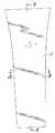
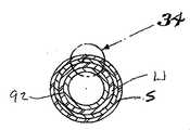
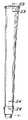
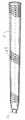
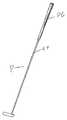
図面を参照すると、図71に、本発明を具現化する単一パネルのグリップGが、ゴルフクラブGCのシャフト55に取り付けられた状態で示されている。図72に、単一パネルのパターのグリップPGが、パターPのシャフト57に取り付けられた状態で示されている。ここで残りの図面を参照すると、好ましい形態のグリップGは、通常の構成の弾性のある下層のスリーブUのまわりに巻き付けられて接着された、互いに結合したポリウレタン60とフェルト62との層で形成された単一パネルSを含む。
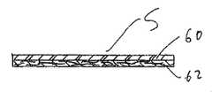
より具体的には、図1、図2及び図3を参照すると、フェルト層62は、ポリウレタン層60の内面に結合された外面を有し、該ポリウレタン層は、気孔(図示せず)を形成するように凝固させられることが好ましい。フェルト層は、羊毛、ポリエステル、ナイロン又はこれらの混合物から製造することができる。ナイロン・ポリエステルのフェルトを利用することが好ましい。ポリウレタン層60は、ジメチルホルムアミド(DMF)に溶解させたポリウレタン(例えば、ポリエステル又はポリエーテル)の溶液でフェルトのストリップの一方の側を被覆し、被覆したストリップを水浴に浸してDMFを置換してウレタンを凝固させ、最後に圧力及び熱で水を除く、という通常の方法により形成することができる。ポリウレタン層の固形分は、該ポリウレタン層の所望の固さによって異なる。好ましい固形分溶液は、摂氏25+0.5度で測定した場合、約28.5ないし30.5%であり、約60,000ないし90,000cpsの範囲の粘度である。適切なポリウレタン材料は、以下の企業から購入することができる。
Lidye Chemical社
10F1 Lidye−Commercial Bldg.
22 Naking W.Road,Taipei
Taiwan,R.O.C.
Lidye Chemical社
No.17,Ching Chien 6th Road
Guan in Industrial Area,Guan In Shiang
Taoyuan Hsien,Taiwan,R.O.C.
Lidye Resin(Panyu)社
Xiadao Industrial Park
Liye Road,Dongchong Town
Panyu City,Guangdong Province,PRC.These and other objects and advantages of the present invention will become apparent from the following detailed description, taken in conjunction with the accompanying drawings.
Referring to the drawings, FIG. 71 shows a single panel grip G embodying the present invention attached to a
More specifically, referring to FIGS. 1, 2 and 3, the
Lidye Chemical 10F1 Lidye-Commercial Bldg.
22 Naking W. Road, Taipei
Taiwan, R.A. O. C.
Lidye Chemical No. 17, Ching Chien 6th Road
Guan in Industrial Area, Guan In Shiang
Taoyuan Hsien, Taiwan, R.A. O. C.
Lidye Resin (Panyu) Xiaao Industrial Park
Liye Road, Donghong Town
Panyu City, Guangdong Province, PRC.
ポリウレタン層の厚さは、約0.3ないし0.5ミリメートルであり、フェルト層の厚さは、約0.8ないし1.7ミリメートルであるのが好ましい。ポリウレタン層60は、ゴルフクラブを持つゴルファーの手にクッションをもった握りを与え、プレーヤーの手とグリップとの間に高められた粘着性を与えることにより、ゴルファーの握りを良好にする。フェルト層62は、ポリウレタン層に強度を与え、かつ互いに結合したポリウレタンとフェルトとのパネルを下層のスリーブUに取り付けるための手段として役立つ。
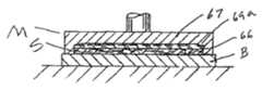
ここで図4ないし図12を参照すると、ポリウレタン層60の外面に摩擦を高めるパターン63(図9)を形成し、単一パネルSの上端及び下端に沿った、加熱押圧成形された水平方向の上縁64及び下縁65と、該パネルの両側に沿った、押圧成形された水平方向の縁66とを形成するために利用される第1の金型Mが示される。金型Mは、基部プレートBと、キャビティ68が形成された加熱プラテン67とを含む。図6に示されるように、キャビティ68の端部には、ポリウレタン層60の上面と係合する垂下突出部69が形成されており、押圧成形された摩擦を高めるパターン63が形成されるようになる。図5においては、垂下突出部69aが凹状縁66を形成する。図8においては、キャビティ68の右側縁部には、パネルSの上端と係合する肩部70が形成されて、ポリウレタン層60に熱により陥凹された上縁64が形成されることが分るであろう。キャビティの左側には、同様の肩部71が形成されて、パネルの下縁に沿って加熱押圧成形された凹状縁65が形成される。The thickness of the polyurethane layer is preferably about 0.3 to 0.5 millimeters and the thickness of the felt layer is preferably about 0.8 to 1.7 millimeters. The
4 to 12, a pattern 63 (FIG. 9) for increasing friction is formed on the outer surface of the
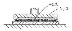
ここで図13ないし図16を参照すると、本発明の単一パネルのグリップを作る際に利用される第2の金型M2が示される。パネルSは、金型Mにおける位置から逆にされた状態で示されている。このような金型は、基部プレート71と、キャビティ73が形成された加熱プラテン72とを含む。基部プレートには、さらに、ポリウレタン層60の外側を受けるキャビティ74が形成されており、フェルト層は、加熱プラテン72のキャビティ73内に受けられる。加熱プラテン72の上側及び下側、並びに側縁には、フェルト層62の上縁及び下縁、並びに、該フェルト層の側縁と係合する垂下周囲肩部76が形成されている。加熱プラテン72が、フェルト層の方向に下向きに付勢されると、その周辺部が肩部76によって押し下げられ、熱が該フェルト層を通して伝達されて、ポリウレタン層60の周囲縁が高密度化される。高密度化は、フェルト層62を通して肩部76から伝達された熱によって行われる。加熱プラテン72には、さらに、図16に示されるフェルト層62の長手方向の中心に沿って切り込み線SL−1を形成する垂下スパー72a(図14)が形成されている。 Referring now to FIGS. 13-16, there is shown a second mold M2 utilized in making the single panel grip of the present invention. Panel S is shown inverted from its position in mold M. Such a mold includes a
ここで図17から図20を参照すると、パネルSの周囲縁を、図17に示されるように、該パネルの上縁及び下縁と係合する一対の回転ナイフ77及び78と、単一の回転ナイフ79とによって削っている状態が示される。ナイフ77及び78は、削られた上縁及び下縁80を形成する。ナイフ79は、図18においては、パネルSの一方の側に削られた縁81を形成するように示され、図19においては、最初の側が削られた後に他方の側に削られた縁82を形成するように示される。圧力プレート83を利用して、削り作業中にパネルを基部プレート84上に固定する。パネルSの両側の削り部分は、図19に見られるように、互いに平行であることに気付くであろう。削り部分は、約4.0ないし6.0ミリメートルの幅を有することが好ましい。
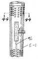
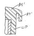
ここで図21ないし図24を参照すると、天然又は合成ゴム、又はプラスチックのような弾性材料で形成された下層のスリーブUが示されている。スリーブUは、その上端に一体のキャップ85を含み、該スリーブの下端には一体のニップル86が形成される。キャップの下側には、周方向下方に延びるスロット87が形成される。このスロット87は、以下に説明されるように、パネルSの上端を受ける。ニップル86には上方に延びるスロット88が形成されており、これは、該スロットの外側に形成された周辺リップ89により構成され、以下に説明される方法により、パネルSの下縁を入れるようになっている。下層のスリーブUには、垂直に延びる切り込み線SL−2が形成されるのが好ましい。Referring now to FIGS. 17-20, the peripheral edge of the panel S, as shown in FIG. 17, a pair of
Referring now to FIGS. 21-24, there is shown a lower sleeve U formed of an elastic material such as natural or synthetic rubber or plastic. The sleeve U includes an
ここで図25ないし図32を参照すると、パネルSが、下層のスリーブUに適用された状態が示されている。図25においては、下層のスリーブUの外面が、ノズル、ブラシなどを用いて接着剤90を受けている状態を示す。図26においては、フェルト層62の内面が、ノズル、ブラシなどを用いて接着剤90を受けている状態を示す。
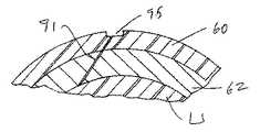
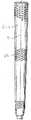
図27においては、パネルSが、下層のスリーブUのまわりに巻き付けられて接着されている状態を示す。この作業の際に、切り込み線SL−1とSL−2とを、位置合わせ状態で配設する。さらに、パネルSの上縁を、下層のキャップ85の周方向のスロット87内に手で挿入し、該パネルの下縁は、周辺リップ89を一時的に外向きに曲げることによってニップル86内に形成されたスロット89内に手で挿入する。図32、図33及び図34に示されるように、パネルSの削られた側縁81及び82は、適当な接着剤90によって互いに接着させられ、該パネルを通って延びる継ぎ目91が形成されるようになる。側縁が削られているために、継ぎ目91は、パネルSの深さに対してある角度で該パネルを通って延び、該パネルの深さに平行に延びる継ぎ目と比較すると、このような継ぎ目の長さは長くなる。長くされた継ぎ目の長さは、より強力な結合をもたらす。継ぎ目は、フェルト層を互いに接合する場所で特に強力である。適当な接着剤90は、ポリクロロプレン(C4H5Cl)及びトルエン(CH5CH3)の化学式を有するものである。パネルSを下層のスリーブUのまわりに巻き付けて接着させているとき、該スリーブは、通常の方法により、折り畳み式マンドレル92上に一時的に支持される。図35ないし図38を参照すると、パネルSの側縁が互いに接着させられた後、下層のスリーブが、基部プレート93上のマンドレル92によって支持され、長手方向に延びる加熱圧力歯94(図36)が、継ぎ目91の外縁のポリウレタン層60に対して付勢される。このような加熱歯は、ポリウレタン層60に、継ぎ目91の外縁と一致させられる小さな凹みを形成して、該継ぎ目をさらに強化する。完成されたグリップGの第1の形態が、図39ないし図41に示される。図40及び図41を参照すると、パネルSの上縁が、キャップのスロット87内にしっかりと配設され、該パネルの底部は、ニップルのスロット88内にしっかりと配設されていることが分るであろう。次に、完成されたグリップをマンドレル92から取り外して、通常の方法によりゴルフクラブGのシャフト上に滑り込ませて接着させるのに備える。Referring now to FIGS. 25 to 32, the panel S is shown applied to the lower sleeve U. FIG. FIG. 25 shows a state in which the outer surface of the lower sleeve U receives the adhesive 90 using a nozzle, a brush, or the like. FIG. 26 shows a state where the inner surface of the felt
FIG. 27 shows a state in which the panel S is wound around the lower sleeve U and bonded thereto. During this operation, the cut lines SL-1 and SL-2 are arranged in an aligned state. Further, the upper edge of the panel S is manually inserted into the
図42ないし図45は、凹み95がノズル又はブラシによって高温のポリウレタン96で充填されている(図42)点を除いては、グリップGにあらゆる点で同様なゴルフクラブのグリップG−1を示す。ポリウレタンが硬化した後、それを適当なブラシ97などによってバフ掛けして、図43に示されるように、グリップの表面に滑らかに溶け込むようにすることができる。或いは、チャネル96を高温のポリウレタンで充填した後、それを磨かない。
ここで図46ないし図49を参照すると、本発明を具現化するグリップG−2の別の修正形態が示されている。この修正形態においては、押圧成形された補強用チャネル95は利用されない。その代わりに、継ぎ目91が形成された後、少量の高温のポリウレタン96を、図45に示されるように、ノズル又はブラシによって該継ぎ目上に被覆する。ポリウレタンが硬化した後、それを適切なブラシ97などによってバフ掛けして、図49に示されるように、グリップの表面に滑らかに溶け込むようにすることができる。或いは、ポリウレタンをバフ掛けしない。FIGS. 42-45 show a golf club grip G-1 that is similar in all respects to grip G, except that
46-49, another modification of grip G-2 embodying the present invention is shown. In this modification, the press-molded reinforcing
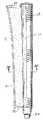
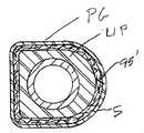
ここで図50ないし図59を参照すると、通常のパターと併せて用いるための単一パネルのグリップPGが示されている。グリップは、前述の下層部Uとほぼ同様な弾性のある下層部UP(図50ないし図54)を含むが、下層のスリーブUPは、環状構成ではない。その代わりに、下層のスリーブUPの前面98は、一般用途のほとんどのパターの設計に従った平らな構成である。下層のスリーブUPが、前述の単一パネルSと同様に、ポリウレタン・フェルト構成の単一パネルSPを受けることを理解されたい。このような単一パネルSPは、単一パネルのグリップG−2について前述されたものと同じ方法により、下層のスリーブのまわりに螺旋状に巻き付けられて接着され、これら2つのグリップの同様の部分には、同様の参照符号が付されている。同様に、チャネル95´も、高温のポリウレタンで充填し、滑らかにバフ掛けして、図57に示されるように、滑らかな表面をもたらすようにすることができる。或いは、熱形成された凹み95を、継ぎ目91´にわたり形成することができ、該継ぎ目は高温のポリウレタンで被覆されて、該ポリウレタンが硬化したときにバフ掛けされて、図56ないし図59に示されるように、該継ぎ目にわたり滑らかな表面をもたらすようにすることができる。パターグリップPGのポリウレタン層の外面は、滑らかにすることもできるし、又は摩擦を高めるパターンで形成することもできる。 Referring now to FIGS. 50-59, there is shown a single panel grip PG for use with a normal putter. The grip includes an elastic lower layer UP (FIGS. 50 to 54) substantially similar to the lower layer U described above, but the lower sleeve UP is not in an annular configuration. Instead, the front surface 98 of the underlying sleeve UP is a flat configuration in accordance with most putter designs for general use. It should be understood that the lower sleeve UP receives a single panel SP of polyurethane felt construction, similar to the single panel S described above. Such a single panel SP is spirally wrapped and bonded around the underlying sleeve in the same manner as described above for the single panel grip G-2, and similar parts of these two grips. Are given the same reference numerals. Similarly, the channel 95 'can also be filled with hot polyurethane and smoothly buffed to provide a smooth surface, as shown in FIG. Alternatively, a
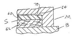
図60ないし図70を参照すると、図27ないし図49のグリップを修正したものが示されている。図60ないし図62においては、ノズル又はブラシによって、高温のポリウレタン96を継ぎ目91にわたって被覆している状態が示される。図63ないし図65においては、ノズル又はブラシによって、高温のポリウレタン96を凹み95に充填している状態が示される。図66は、加熱プラテン100を有する金型M3を示し、該プラテンの下側には、グリップのポリウレタン層60の表面にエンボス加工される摩擦を高めるパターン63のセグメント63aが形成されている。ポリウレタンがまだ高温なうちに、このような加熱プラテン100を、ポリウレタン層の外面に対して継ぎ目91の領域上に押し付ける。この配置により、ポリウレタン層の外側の継ぎ目の外方の領域には、図67の摩擦を高めるセグメントが形成され、該セグメントは、図70に示されるようなグリップの外面の本体上に成型された摩擦を高めるパターン63と合体する。
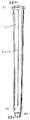
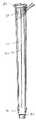
ここで図71を参照すると、前述の説明に従って製造されたグリップGが入れ子式に固定されたハンドル55を有するゴルフクラブGCが示されている。図72は、パターPのハンドル57に入れ子式に適用されたパターグリップPGを示す。Referring to FIGS. 60-70, a modification of the grip of FIGS. 27-49 is shown. 60 to 62 show a state in which
Referring now to FIG. 71, there is shown a golf club GC having a
本発明を具現化するグリップの外面を、ブラシ又は吹き付けを用いてポリウレタンの薄層(図示せず)で被覆することにより、該表面が保護され、それに粘着性が加えられ、その耐久性が増加されるようになることを理解されたい。
本発明のゴルフクラブグリップは、前述の既存の巻き付け式グリップと比較して幾つかの利点をもたらす。さらに、このようなグリップは、プロ及びローハンディキャップのゴルファーにはよく知られている成型された一体型のグリップの外観を有する。このようなゴルファーの幾人かは、従来型ではない巻き付け式クラブを使用したがらないが、本発明の構造的に一体型のグリップは、巻き付け式グリップにおける緩衝性及び粘着性の特性をもたらすため、彼らは、このようなグリップを用いてプレイすることに前向きである。
本発明の範囲を離れることなく、種々の修正及び変更が、上述された詳細な説明に対してなされ得る。By covering the outer surface of the grip embodying the present invention with a thin layer of polyurethane (not shown) using a brush or spray, the surface is protected and added to it, increasing its durability. Please understand that it will be.
The golf club grip of the present invention provides several advantages over the existing wrapping grip described above. Furthermore, such a grip has the appearance of a molded integral grip that is well known to professional and low handicap golfers. Some of these golfers are reluctant to use a non-conventional wrap-around club, but the structurally integral grip of the present invention provides the cushioning and tack characteristics of the wrap-around grip. They are willing to play with such grips.
Various modifications and changes may be made to the detailed description above without departing from the scope of the invention.
60:ポリウレタン層
62:フェルト層
81、82:側縁
91:継ぎ目
95:凹み60: polyurethane layer 62: felt
Claims (20)
Translated fromJapaneseフェルトの内側層と、該内側層に結合され、該内側層より薄い厚さのポリウレタンの外側層とを含むほぼ均一な厚さの単一パネルが、前記ゴルフクラブのハンドルの上に配置された下側層のまわりに巻き付けられて該下側層に接着され、
前記単一パネルの一方の側縁が前記フェルトの内側層から前記ポリウレタンの外側層まで斜めに削られた傾斜縁部を構成し、他方の側縁が前記ポリウレタンの外側層から前記フェルトの内側層まで斜めに削られた傾斜縁部を構成しており、
前記一方の側縁により形成される前記傾斜縁部と、前記他方の側縁により形成される前記傾斜縁部とは、該一方の側縁における前記フェルトの内側層と該他方の側縁における前記フェルトの内側層とが互いに当接し互いに接着させられ、かつ、該一方の側縁における前記ポリウレタンの外側層と該他方の側縁における前記ポリウレタンの外側層とが互いに当接し互いに接着させられた状態になるように、互いに当接し互いに接着させられており、前記一方の側縁と前記他方の側縁とが、前記フェルトの内側層の内面から前記ポリウレタンの外側層の外面に至る範囲において長手方向の継ぎ目を形成しており、該長手方向の継ぎ目は、前記単一パネルの厚さ方向に斜めに延びるようになったことを特徴とするゴルフクラブグリップ。A grip for a golf club handle,
An inner layer offelt, is bonded to theinner layerandan outer layer ofpolyurethane thinner than the inner layerthickness includingMuhobo single panelhaving a uniform thickness,it is disposed on the golf club handle It was wound around thelower layeris adhered to said lower layer,
One side edge of thesingle panelconstitutes an inclined edge that is cut obliquely from the inner layer of the felt to the outer layer of the polyurethane, and the other side edge from the outer layer of the polyurethane to the inner layer of the felt Consists of an inclined edge that is cut diagonally to
The inclined edge formed by the one side edge and the inclined edge formed by the other side edge are the inner layer of the felt at the one side edge and the above-mentioned at the other side edge, respectively. A state in which the inner layer of the felt is in contact withand adhered to each other,and the outer layer of the polyurethane in one side edge and the outer layer of the polyurethane in the other side edge are in contact with each other and are adhered to each other So that the one side edge and the other side edge are in the longitudinal direction from the inner surface of the inner layer of the felt to the outer surface of the outer layer of the polyurethane. A golf club grip, wherein the seam in the longitudinal direction extends obliquely in the thickness direction of the single panel .
前記下側層が、下方に向いたスロットが形成されたキャップと、上方に向いた周方向のスロットが形成されたニップルとを含み、前記ニップルの前記スロットの外側部分が周辺リップにより形成され、
前記パネルの上縁が前記キャップの前記スロットにしっかりと保持され、前記パネルの下縁が前記周辺リップにより前記ニップルの前記スロットにしっかりと保持された、
ことを特徴とするゴルフクラブグリップ。A grip for a handle ofa golf club accordingto claim 1 ,
The lower layer includes a cap formed with a downward-facing slot and a nipple formed with an upward-facing circumferentialslot , the outer portion of theslot of the nipplebeing formed by a peripheral lip;
The upper edge of the panel is securely held inthe slot of the cap, the lower edge of the panelis securely held in the slot of the nipple by the peripheral lip,
A golf club grip characterized by that.
前記ポリウレタン層の外側に摩擦を高めるパターンが形成されたことを特徴とするゴルフクラブグリップ。A grip for a handle ofa golf club accordingto claim 1 ,
A golf club grip, wherein a pattern for increasing frictionis formed on the outside of the polyurethane layer.
前記ポリウレタンの外側層は、前記継ぎ目の長さに沿って加熱押圧成形されて、該継ぎ目が補強され、
加熱押圧成形された前記ポリウレタンの外側層は、ポリウレタンを付着させた付着層により覆われており、
前記ポリウレタンの付着層には、摩擦を高めるパターンが、前記ポリウレタンの前記外側層の外側に形成された前記摩擦を高めるパターンに連続するように形成された、
ことを特徴とするゴルフクラブグリップ。A grip for a handle ofa golf club accordingto claim 12 ,
The outer layer of polyurethane is heat pressedalong the length of the seam to reinforce the seam,
The outer layer of the polyurethane formed by heating and pressing iscovered with anadhesion layer to which polyurethane is adhered,
Wherein the deposit of polyurethane, a pattern to increase the friction, whichis formed so as to becontinuous to the pattern of increasing the friction formed on the outside ofsaid outer layer of said polyurethane,
A golf club grip characterized by that.
下側層を準備し、
フェルトの内側層に結合された該内側層より薄い厚さのポリウレタンの外側層を含み、ほぼ均一の厚さを有する単一パネルを準備し、
前記単一パネルを前記下層のスリーブのまわりに巻き付けて接着し、
前記単一パネルの一方の縁を前記フェルトの内側層の内面から前記ポリウレタンの外側層の外面まで斜めに削って第1の傾斜縁部を形成し、
前記単一パネルの他方の縁を前記ポリウレタンの外側層の外面から前記フェルトの内側層の内面まで斜めに削って第2の傾斜縁部を形成し、
前記第1の傾斜縁部における前記フェルトの内側層が前記第2傾斜縁部における前記フェルトの内側層に接触し、前記第1の傾斜縁部における前記ポリウレタンの外側層が前記第2傾斜縁部における前記ポリウレタンの外側層に接触する状態になるように、前記パネルの前記第1及び第2傾斜縁部を互いに当接させかつ互いに接着させて、前記一方の側縁と前記他方の側縁とにより、前記フェルトの内側層の内面から前記ポリウレタンの外側層の外面に至る範囲において、前記単一パネルの厚さ方向に斜めに延びる長手方向の継ぎ目を形成する、
というステップを含むことを特徴とする方法。A method for making a grip for a golf club handle,
Prepare thelower layer,
Providing a single panel having asubstantially uniform thickness comprising an outer layerof polyurethane having athickness less than the inner layer bonded to the inner layer of felt;
Wrap and bond the single panel around the lower sleeve;
One edge of the single panel is diagonally shaved from the inner surface of the inner layer of the felt to the outer surface of the outer layer of polyurethane to form a first inclined edge,
The other edge of the single panel is diagonally shaved from the outer surface of the outer layer of polyurethane to the inner surface of the inner layer of the felt to form a second inclined edge;
An inner layer of the felt at the first inclined edge contacts an inner layer of the felt at the second inclined edge, and an outer layer of the polyurethane at the first inclined edge is the second inclined edge. as a state of contact with the outer layer of the polyurethane in, is adhered abutted allowed and together with each other the first and second inclined edges of the panel,said the one side edge and the other side edge In the range from the inner surface of the inner layer of the felt to the outer surface of the outer layer of the polyurethane, a longitudinal seam extending obliquely in the thickness direction of the single panel is formed .
A method comprising the steps of:
摩擦を高めるパターンを前記ポリウレタンの外側層の外側に形成する、
ステップを含むことを特徴とする方法。A method for making a grip for a handle ofa golf club accordingto claim 14 comprising the steps of:
Forming a friction enhancing pattern on the outside of the polyurethane outer layer;
A method comprising steps.
前記単一パネルが前記下側層のまわりに巻き付けられるとき、前記単一パネルの上縁を前記キャップの前記周方向のスロット内に押し込み、前記単一パネルの下縁を前記ニップルの前記周方向のスロット内に押し込む、
というステップを含む方法。Saidlower layer, and a cap slots are formed facing downward,to claim 17 when derRu those containing a nipple of upwardly facing constituted by peripheral lip circumferential slots are formedA method as described ,
Whensaid single panel is wound around thelower layer, the pushing the upper edge of thesingle panel in the circumferential direction in the slot of the cap, the circumferential direction of the nipple thelower edge of saidsingle panel Push it into the slot,
A method comprising the steps of:
前記単一パネルが前記下側層のまわりに巻き付けられるとき、前記単一パネルの上縁を前記キャップの前記周方向のスロット内に押し込み、前記単一パネルの下縁を前記ニップルの前記周方向のスロット内に押し込む、
というステップを含む方法。Claim 14 when thelower layeris one containing a cap slots are formed facing downward, and a nipple of the upwardly facing constituted by peripheral lip circumferential slots are formedThe method
Whensaid single panel is wound around thelower layer, the pushing the upper edge of thesingle panel in the circumferential direction in the slot of the cap, the circumferential direction of the nipple thelower edge of saidsingle panel Push it into the slot,
A method comprising the steps of:
Priority Applications (1)
| Application Number | Priority Date | Filing Date | Title |
|---|---|---|---|
| US11/062,046US7470199B2 (en) | 2003-03-18 | 2005-02-18 | Single panel golf club grip |
Applications Claiming Priority (1)
| Application Number | Priority Date | Filing Date | Title |
|---|---|---|---|
| US10/392,480US6857971B2 (en) | 2003-03-18 | 2003-03-18 | Single panel golf club grip |
Publications (2)
| Publication Number | Publication Date |
|---|---|
| JP2004275719A JP2004275719A (en) | 2004-10-07 |
| JP4095944B2true JP4095944B2 (en) | 2008-06-04 |
Family
ID=32850518
Family Applications (1)
| Application Number | Title | Priority Date | Filing Date |
|---|---|---|---|
| JP2003325606AExpired - Fee RelatedJP4095944B2 (en) | 2003-03-18 | 2003-09-18 | Single panel golf club grip |
Country Status (7)
| Country | Link |
|---|---|
| US (4) | US6857971B2 (en) |
| EP (1) | EP1464365B1 (en) |
| JP (1) | JP4095944B2 (en) |
| CN (1) | CN1250306C (en) |
| DE (1) | DE60327595D1 (en) |
| ES (1) | ES2326074T3 (en) |
| TW (1) | TWI232119B (en) |
Families Citing this family (65)
| Publication number | Priority date | Publication date | Assignee | Title |
|---|---|---|---|---|
| US6695713B2 (en) | 2000-02-04 | 2004-02-24 | Ben Huang | All-weather golf club grip |
| US7510483B2 (en)* | 2004-07-09 | 2009-03-31 | William S. Tremulis | Golf club grip |
| US7585230B2 (en) | 2003-03-18 | 2009-09-08 | Ben Huang | Single panel golf club grip with EVA inside layer |
| US6857971B2 (en)* | 2003-03-18 | 2005-02-22 | Ben Huang | Single panel golf club grip |
| US6843732B1 (en)* | 2003-12-23 | 2005-01-18 | Ben Huang | Multi-segment single panel grip |
| US7137904B2 (en)* | 2002-06-11 | 2006-11-21 | Ben Huang | Spiral wrap golf club grip |
| US9440128B2 (en) | 2002-06-11 | 2016-09-13 | Ben Huang | Method of making a grip |
| US8360898B2 (en) | 2002-06-11 | 2013-01-29 | Ben Huang | Grip |
| US7862446B2 (en) | 2007-08-14 | 2011-01-04 | Ben Huang | Grip having a varied gripping surface |
| US6733401B1 (en)* | 2003-01-21 | 2004-05-11 | Ben Huang | Golf club handle grip |
| US7461474B1 (en) | 2003-10-02 | 2008-12-09 | Clive S. Lu | Display grip for sports equipment |
| WO2005115563A1 (en)* | 2004-05-19 | 2005-12-08 | Ben Huang | Single panel golf club grip with eva inside layer |
| US7232378B2 (en)* | 2004-12-01 | 2007-06-19 | Leo Jaw | Shock-absorbable grip |
| US7189168B2 (en)* | 2005-06-03 | 2007-03-13 | Chin-Pai Lin | Golf club grip |
| US7186189B2 (en) | 2005-07-01 | 2007-03-06 | Ben Huang | Panel grip with modified seam |
| USD544934S1 (en)* | 2005-08-23 | 2007-06-19 | Dennis De Gruccio | Combined putter grip and ball retriever |
| US20070167252A1 (en)* | 2006-01-13 | 2007-07-19 | Leo Jaw | Grip for sports gear |
| US8491409B2 (en)* | 2006-01-24 | 2013-07-23 | Eaton Corporation | Silicone grips for golf clubs |
| US7566375B2 (en) | 2006-01-25 | 2009-07-28 | Ben Huang | Panel grip with cut-outs and inserts |
| US7448958B2 (en)* | 2006-01-25 | 2008-11-11 | Ben Huang | Panel grip with cut-outs and inserts |
| DE502007001208D1 (en)* | 2006-02-02 | 2009-09-17 | Head Technology Gmbh | Grip and handle for ball game rackets |
| USD548807S1 (en)* | 2006-04-03 | 2007-08-14 | Lee Miller | Golf club grip underlisting |
| USD548298S1 (en)* | 2006-04-03 | 2007-08-07 | Lee Miller | Golf club grip underlisting |
| US7347792B2 (en) | 2006-05-22 | 2008-03-25 | Ben Huang | Decorative golf club grip |
| US7458903B2 (en)* | 2006-06-08 | 2008-12-02 | Eaton Corporation | Hand grip and method of making same |
| FR2903021B1 (en)* | 2006-06-29 | 2008-12-05 | Major Sports Sa | COATING STRIP FOR HAND RACKET HANDLE |
| TWM314627U (en)* | 2007-01-19 | 2007-07-01 | High Cedar Entpr Co Ltd | Grip cover |
| US7458902B2 (en)* | 2007-03-14 | 2008-12-02 | Eaton Corporation | Changeable golf grip |
| US7770321B2 (en)* | 2007-03-19 | 2010-08-10 | Ben Huang | Fishing pole grip |
| US7862445B2 (en) | 2007-03-21 | 2011-01-04 | Ben Huang | Grip having a stabilized gripping surface |
| US7798912B2 (en)* | 2007-09-17 | 2010-09-21 | Eaton Corporation | Variable hardness hand grip |
| US8105522B2 (en) | 2008-10-29 | 2012-01-31 | Eaton Corporation | Compression mold and molding process |
| WO2010078546A1 (en) | 2009-01-05 | 2010-07-08 | Maxxcel Sports Llc | Grip trainer |
| US8641552B2 (en)* | 2009-03-25 | 2014-02-04 | Clive S. Lu | Grip for sporting equipment |
| US20110172024A1 (en)* | 2009-03-25 | 2011-07-14 | Lu Clive S | Grip for sporting equipment |
| US20100248858A1 (en) | 2009-03-25 | 2010-09-30 | Lu Clive S | Grip For Sporting Equipment |
| US8590205B2 (en) | 2009-11-18 | 2013-11-26 | Ben Huang | Exchangeable handle for use with a fishing pole |
| US8424236B2 (en) | 2009-05-11 | 2013-04-23 | Ben Huang | Multi-layered grip for use with fishing poles |
| EP2241182A1 (en)* | 2009-04-10 | 2010-10-20 | Ben Huang | Multi-layered grip for use with fishing poles |
| US9090307B2 (en) | 2009-04-28 | 2015-07-28 | Ben Huang | Grip for the handle of an article |
| EP2241354A1 (en) | 2009-04-10 | 2010-10-20 | Ben Huang | Ultralight grip for use with golf clubs and the like |
| US8518505B2 (en) | 2009-04-10 | 2013-08-27 | Ben Huang | Multi-layered grip |
| US20100273568A1 (en)* | 2009-04-28 | 2010-10-28 | Ben Huang | Ultralight grip for use with golf clubs and the like |
| US9661833B2 (en) | 2009-04-10 | 2017-05-30 | Ben Huang | Multi-layered grip |
| US8296907B2 (en)* | 2009-05-15 | 2012-10-30 | Eaton Corporation | Light weight grip and method of making same |
| US8480510B2 (en) | 2009-08-28 | 2013-07-09 | Ben Huang | Sleeve member for use in golf club grips and the like |
| US8226497B2 (en)* | 2009-11-09 | 2012-07-24 | Hong-Sung Chu | Golf club grip with an axial seam structure |
| US8272973B2 (en)* | 2010-01-01 | 2012-09-25 | Lu Clive S | Golf club grip |
| US20110207546A1 (en)* | 2010-02-22 | 2011-08-25 | Vitorino Tito M | Golf Club Grip |
| US8308581B2 (en) | 2010-05-05 | 2012-11-13 | Chien-Kuo Ou | Water repellent golf club leather grip and manufacturing method thereof |
| US8641559B2 (en) | 2011-03-11 | 2014-02-04 | Nike, Inc. | Golf ball with adjustable tackiness |
| US8480508B2 (en) | 2011-09-21 | 2013-07-09 | Hong-Sung Chu | Golf club grip and method of making the same |
| USD696368S1 (en) | 2012-11-07 | 2013-12-24 | Ben Huang | Golf club grip |
| US9199146B2 (en)* | 2013-03-14 | 2015-12-01 | Lamkin Corporation | Golf grip with raked gripping features |
| ES2553785B1 (en)* | 2014-06-10 | 2016-09-13 | Emilio ROCHE SALVADOR | Cover for rackets, shovels or similar tools |
| US10653124B2 (en) | 2017-05-03 | 2020-05-19 | Winn Incorporated | Reel component and method of manufacturing same |
| USD844744S1 (en) | 2017-05-03 | 2019-04-02 | Winn Incorporated | Reel component |
| USD847298S1 (en) | 2017-05-18 | 2019-04-30 | Winn Incorporated | Reel component |
| USD849166S1 (en) | 2017-12-07 | 2019-05-21 | Ssg International, Llc | Golf putter grip |
| US10099101B1 (en) | 2017-12-07 | 2018-10-16 | Ssg International, Llc | Golf club grip with sensor housing |
| US10912972B1 (en)* | 2019-12-20 | 2021-02-09 | Lawrence Fortin | Single-handed golf swing apparatus |
| USD1070196S1 (en) | 2022-12-22 | 2025-04-08 | Towerstar Pets, Llc | Apparatus for pet hair removal |
| USD1069272S1 (en) | 2022-12-22 | 2025-04-01 | Towerstar Pets, Llc | Apparatus for pet hair removal |
| USD1073208S1 (en) | 2022-12-22 | 2025-04-29 | Towerstar Pets, Llc | Apparatus for pet hair removal |
| USD1083265S1 (en) | 2023-09-07 | 2025-07-08 | Towerstar Pets, Llc | Apparatus for pet hair removal |
Family Cites Families (145)
| Publication number | Priority date | Publication date | Assignee | Title |
|---|---|---|---|---|
| US571025A (en)* | 1896-11-10 | Removable cover for bicycle handle-bars | ||
| US979266A (en) | 1910-08-31 | 1910-12-20 | John R Dean | Base-ball bat. |
| US1008604A (en)* | 1911-07-28 | 1911-11-14 | Golladay Lake | Hand-protector. |
| US1017565A (en) | 1911-11-04 | 1912-02-13 | Allan E Lard | Grip or handle. |
| US1139843A (en) | 1913-10-16 | 1915-05-18 | Robert B Brown | Handle-grip. |
| US1345505A (en)* | 1918-10-19 | 1920-07-06 | Charles A Persons | Handle-grip |
| US1435088A (en) | 1920-12-02 | 1922-11-07 | George J Renner | Handle grip |
| US1528190A (en) | 1923-07-14 | 1925-03-03 | John D Howe | Golf club |
| US1522635A (en) | 1924-01-18 | 1925-01-13 | Kroydon Co | Golf club |
| US1617972A (en)* | 1925-08-26 | 1927-02-15 | Robert S Wallace | Grip for golf clubs |
| US1890037A (en)* | 1930-11-21 | 1932-12-06 | Herbert B Johnson | Rubber covered article |
| US2000295A (en) | 1931-12-31 | 1935-05-07 | Leonard A Young | Handgrip for golf clubs and the like |
| US1943399A (en) | 1932-02-23 | 1934-01-16 | Smith Kenneth | Golf club seal and method of making the same |
| US2103889A (en) | 1933-07-20 | 1937-12-28 | Kroydon Company | Golf club handle |
| US2149911A (en) | 1935-05-25 | 1939-03-07 | Spalding & Bros Ag | Golf club grip |
| US2086062A (en) | 1935-09-16 | 1937-07-06 | Al Espinosa | Ventilated handle |
| US2206056A (en) | 1935-10-30 | 1940-07-02 | Tufide Products Corp | Method and apparatus for making fibrous sheetings |
| US2225839A (en) | 1938-06-17 | 1940-12-24 | Jr William R Moore | Golf club |
| US2221421A (en)* | 1938-11-25 | 1940-11-12 | Spalding A G & Bros Inc | Athletic implement and method of making the same |
| US2449575A (en)* | 1945-10-25 | 1948-09-21 | Seymour K Wilhelm | Cushioned knob |
| US2523637A (en)* | 1946-11-15 | 1950-09-26 | Dow F Stanfield | Grip for handles of poles, clubs, and like articles |
| US2671660A (en) | 1949-07-12 | 1954-03-09 | C S I Sales Company | Grip for golf clubs |
| US2671680A (en)* | 1951-01-19 | 1954-03-09 | Myron B Stevens | Telescopic structure |
| US2690338A (en)* | 1951-06-13 | 1954-09-28 | Brocke Ben Henry De | Golf club grip |
| US2772090A (en) | 1952-08-27 | 1956-11-27 | Spalding A G & Bros Inc | Lightweight grip |
| US2984486A (en)* | 1959-02-05 | 1961-05-16 | Lloyd J Jones | Slip-proof sleeve for a baseball bat handle |
| US3087729A (en) | 1959-08-03 | 1963-04-30 | Lamkin Leather Company | Slip-on handle grip |
| US3095198A (en)* | 1960-08-02 | 1963-06-25 | Gasche Fred | Swivel grip for golf clubs |
| US3140873A (en) | 1960-11-15 | 1964-07-14 | Goodwin Mfg & Dev Company Inc | Grooved golf club handle sleeve and stretchable insert to fill said groove |
| BE619783A (en)* | 1961-07-05 | |||
| GB979242A (en)* | 1963-01-03 | 1965-01-01 | John Henry Onions | Improvements relating to grips for the handles or shafts of ball striking devices for use in games |
| US3366384A (en) | 1965-07-30 | 1968-01-30 | Lamkin Leather Company Inc | Golf club grip and method for making same |
| US3606325A (en) | 1970-04-27 | 1971-09-20 | Lamkin Leather Co | Golf club grip |
| US3857745A (en) | 1972-04-18 | 1974-12-31 | Fisher & Paykel | Method of covering articles with leather |
| JPS5549192B2 (en) | 1973-05-07 | 1980-12-10 | ||
| US4012039A (en) | 1973-07-13 | 1977-03-15 | Joe Hall, Jr. | Permanent form-fitting, non-slip cover for handgripping portion of baseball bats, golf clubs and the like |
| DE2345257C2 (en) | 1973-09-07 | 1975-09-18 | Bayer Ag, 5090 Leverkusen | Process for the production of microporous sheet-like structures based on polyurethane |
| US4052061A (en)* | 1975-07-11 | 1977-10-04 | Stewart Samuel F | Racket weighting means |
| US4015851A (en) | 1976-02-09 | 1977-04-05 | Elastomeric Products Inc. | Rubber grip for tennis racket handles |
| US4133529A (en)* | 1977-08-01 | 1979-01-09 | Joseph Gambino | Golf grip |
| US4216251A (en) | 1977-09-05 | 1980-08-05 | Kuraray Co., Ltd. | Method of producing a leather-like sheet material having a high-quality feeling |
| US4284275A (en) | 1979-10-11 | 1981-08-18 | Fletcher Herbert E | Polyurethane gripping material |
| US4448922A (en) | 1980-09-18 | 1984-05-15 | Norwood Industries, Inc. | Coagulated polyurethane coating compositions |
| US4358499A (en) | 1980-12-18 | 1982-11-09 | The General Tire & Rubber Company | Dimensionally stable PVC roof membrane |
| US4347280A (en) | 1981-07-08 | 1982-08-31 | Geos Corporation | Shock absorbing sheet material |
| DE3136281A1 (en)* | 1981-09-12 | 1983-03-24 | Hoechst Ag, 6000 Frankfurt | ADDITIONAL PRODUCTS FROM TRIAETHANOLAMINE CONDENSATES AND BIS-GLYCIDYL ETHERS AND THEIR USE |
| US4651991A (en)* | 1985-12-12 | 1987-03-24 | Mcduff Michael A | Handle covering |
| US4765856A (en)* | 1986-03-26 | 1988-08-23 | Doubt Ruxton C | Process for manufacturing custom moldable hand grip |
| US4662415A (en)* | 1986-04-02 | 1987-05-05 | Proutt Gordon R | Cover for a golf club handle |
| AT384554B (en)* | 1986-06-03 | 1987-12-10 | Tyrolia Freizeitgeraete | SKI BRAKE |
| DE3702582A1 (en)* | 1987-01-29 | 1988-08-11 | Basf Ag | CONTINUOUS PROCESS FOR PRODUCING MOLDING MATERIALS BASED ON POLYPHENYLENE ETHERS AND POLYAMIDES |
| US4848667A (en)* | 1987-04-30 | 1989-07-18 | Raleigh Equities Ltd. | Water spray nozzle including combined intake nozzle and valve structure |
| US5055340A (en)* | 1987-08-06 | 1991-10-08 | Asahi Kagaku Kogyo Co., Ltd. | Grip tape |
| US4919420A (en)* | 1987-08-28 | 1990-04-24 | Daiwa Golf Co., Ltd. | Grip of a golf club and a manufacturing method thereof |
| US4941232A (en)* | 1987-10-07 | 1990-07-17 | Bettcher Industries, Inc. | Slip resistant, cushioning cover for handles |
| US4878667A (en) | 1988-05-24 | 1989-11-07 | John Tosti | Replaceable, reusable golf club grip |
| JPH0741731Y2 (en) | 1990-01-08 | 1995-09-27 | 株式会社小森コーポレーション | Paper flow prevention device in the paper output section of the printing machine |
| AU8303891A (en) | 1990-07-19 | 1992-02-18 | Cabot Safety Corporation | Vibration damping handle grip and grip cover |
| US5118107A (en)* | 1990-10-31 | 1992-06-02 | Bucher Inc. | Rain cover for golf club handle |
| US5813921A (en) | 1991-01-14 | 1998-09-29 | Huang; Ben | Sleeve-type grip for golf shafts |
| US5890972A (en)* | 1991-01-14 | 1999-04-06 | Huang; Ben | Spiral protrusion type handle grip |
| US5730669A (en)* | 1991-01-14 | 1998-03-24 | Huang; Ben | Handle grip and method of making same |
| US5584482A (en)* | 1995-04-12 | 1996-12-17 | Huang; Ben | Sleeve-type golf club grip |
| US5645501A (en)* | 1991-01-14 | 1997-07-08 | Huang; Ben | Grip construction |
| US5797813A (en)* | 1991-01-14 | 1998-08-25 | Huang; Ben | Handle grip |
| US5695418A (en) | 1991-01-14 | 1997-12-09 | Huang; Ben | Shock absorbing grip for racquets and the like |
| US5895329A (en) | 1991-01-14 | 1999-04-20 | Huang; Ben | Golf club shaft grip |
| US5772524A (en)* | 1991-01-14 | 1998-06-30 | Huang; Ben | Water retarding golf club grip |
| US5671923A (en)* | 1991-01-14 | 1997-09-30 | Huang; Ben | Grip for golf shafts |
| US5374059A (en) | 1991-01-14 | 1994-12-20 | Huang; Ben | Shock absorbing grip for racquets and the like |
| US5123646A (en)* | 1991-04-19 | 1992-06-23 | Bill Overby | Apparatus and method for removing grips |
| US5127650A (en) | 1991-07-24 | 1992-07-07 | Schneller Arthur J | Golf putter and method for putting |
| US5261665A (en) | 1992-02-11 | 1993-11-16 | Robert A. Paley, Inc. | Golf club grip formed of a plurality of materials and method of manufacture thereof |
| CN2139008Y (en) | 1992-09-26 | 1993-07-28 | 卢建文 | Golf ball rod body |
| US5347684A (en)* | 1992-10-13 | 1994-09-20 | Jackson Linda J | Grip cover |
| TW205010B (en)* | 1992-12-12 | 1993-05-01 | Ryh-Ming Chen | Making process for dumbbells enveloped with stainless steel |
| CN2163667Y (en) | 1993-02-25 | 1994-05-04 | 李明瑞 | Positioning collar for golf clubs |
| US5839983A (en) | 1993-07-09 | 1998-11-24 | Kramer; Robert M. T. | Adjustable grips for a ball bat |
| US5611533A (en)* | 1994-05-16 | 1997-03-18 | Williams; John P. | Gripping sleeve apparatus and method of using the same |
| US5427376A (en)* | 1994-06-14 | 1995-06-27 | Cummings; Patricia M. | Golf club grip with first indicia to indicate where the thumbs and fingers of a player are to be located and other indicia to indicate other areas |
| US5511445A (en)* | 1994-10-11 | 1996-04-30 | Hildebrandt; Robert C. | Flexible hand grip for handles |
| US5480146A (en) | 1994-12-08 | 1996-01-02 | Comer; Larry D. | Golf grip with recesses to insure proper hand positioning of a user |
| US5671926A (en) | 1994-12-23 | 1997-09-30 | Hagey; Edward H. | Tennis racket with enhanced hand grip |
| IT239384Y1 (en) | 1995-03-09 | 2001-02-26 | Selle San Marco Di Girardi Com | BICYCLE SADDLE WITH INSERTS AND EMBROIDERY TO REDUCE THE SLIDING OF THE USER'S BODY DURING THE RIDE |
| US5570884A (en)* | 1995-04-10 | 1996-11-05 | Carps; Dan | Ergonomic underlay for hand grips |
| US5577722A (en)* | 1995-07-07 | 1996-11-26 | Glassberg; Corey | Bat grip device |
| TW351205U (en)* | 1995-09-13 | 1999-01-21 | Ben Huang | Tubular golf club grip |
| US5781963A (en)* | 1995-10-06 | 1998-07-21 | The Stanley Works | Coextruded screwdriver handle and method of making same |
| US5624116A (en)* | 1995-10-23 | 1997-04-29 | Prince Sports Group, Inc. | Grip for sports racquet |
| US5626527A (en)* | 1995-12-13 | 1997-05-06 | Eberlein; Timothy | Golf grip installable over pre-existing grip |
| US5595544A (en)* | 1995-12-27 | 1997-01-21 | Roelke; Harold R. | Putter grip with stabilizing members |
| US5816933A (en)* | 1995-12-28 | 1998-10-06 | Huang; Ben | Golf club shaft grip |
| US5890260A (en)* | 1996-07-01 | 1999-04-06 | Gaunt; John C. | Hand saver |
| US5730662A (en) | 1996-10-21 | 1998-03-24 | Rens; Peter J. | Grip assembly and method |
| US6197392B1 (en) | 1997-01-08 | 2001-03-06 | Michael G. Jones | Low-odor single element equipment grip |
| US5857929A (en) | 1997-01-23 | 1999-01-12 | Huang; Ben | Two piece handle grip |
| US6244975B1 (en)* | 1997-01-23 | 2001-06-12 | Ben Huang | Water resistant handle grip |
| US5851632A (en) | 1997-02-03 | 1998-12-22 | Chen; Sam Hsin-Shun | Grip tape for handle |
| CN2288744Y (en) | 1997-03-26 | 1998-08-26 | 广州朝昌橡塑五金制品有限公司 | Easy-to-insert rubber handle of golf club |
| US5867868A (en) | 1997-06-05 | 1999-02-09 | Ward; James D. | Detachable grip for elongated members |
| US6048275A (en) | 1997-07-02 | 2000-04-11 | Gedeon; Robert J. | Golf putter |
| US6558270B2 (en)* | 1997-10-16 | 2003-05-06 | Benjamin J. Kwitek | Grip |
| US6036607A (en)* | 1998-03-02 | 2000-03-14 | Finegan; Christopher H. | Adjustable grip |
| AUPP442798A0 (en)* | 1998-07-01 | 1998-07-23 | Grip Master Company Pty Ltd, The | A grip for a handle or shaft |
| JP4289515B2 (en) | 1998-08-05 | 2009-07-01 | 株式会社シマノ | Grip manufacturing method |
| US6261191B1 (en) | 1999-07-27 | 2001-07-17 | Sam Hsin-Shun Chen | Multi-surface grip tape for handle |
| US6506128B1 (en) | 1999-10-19 | 2003-01-14 | James Pierce Bloom, Jr. | Counterweighted golf club |
| US6551198B2 (en) | 2000-02-04 | 2003-04-22 | Ben Huang | Golf club grip assembly |
| US6663500B2 (en) | 2000-02-04 | 2003-12-16 | Ben Huang | All-weather composite grip for golf clubs |
| US6386989B1 (en) | 2000-02-04 | 2002-05-14 | Ben Huang | Golf club grip assembly |
| US6361450B1 (en) | 2000-02-04 | 2002-03-26 | Ben Huang | Golf club shaft grip assembly |
| US6635688B2 (en) | 2000-06-28 | 2003-10-21 | World Properties, Inc. | Composite polyurethane foams and method of manufacture thereof |
| CN1332022A (en) | 2000-07-07 | 2002-01-23 | 林育萱 | Golf club grip, manufacturing method and molding device thereof |
| CN2438768Y (en) | 2000-07-10 | 2001-07-11 | 罗忠万 | Seamless anti-collision safety structure |
| US6676534B2 (en) | 2000-10-30 | 2004-01-13 | Ben Huang | Composite grip for golf clubs |
| US6629901B2 (en) | 2000-11-09 | 2003-10-07 | Ben Huang | Composite grip for golf clubs |
| CN2444645Y (en) | 2000-11-21 | 2001-08-29 | 陈晴祺 | Improved structure of handle of golf dub |
| US6503153B2 (en)* | 2000-12-21 | 2003-01-07 | High Cedar Enterprise Co., Ltd. | Grip tape having multiple gripping functions |
| US20020107088A1 (en)* | 2001-02-07 | 2002-08-08 | Lamkin Robert E. | Grip for sporting implement |
| US20020142900A1 (en)* | 2001-03-28 | 2002-10-03 | Mao-Hsiu Wang | Handle of exercise device |
| CN2477228Y (en) | 2001-03-29 | 2002-02-20 | 陈永祥 | Handle structure of golf club |
| US6627027B2 (en) | 2001-08-13 | 2003-09-30 | Ben Huang | Method of making a shock absorbing grip for golf clubs and the like |
| TW493460U (en) | 2001-08-21 | 2002-07-01 | Franco C Manuel | Composite-material-made handle of golf club |
| US6652398B2 (en)* | 2001-08-27 | 2003-11-25 | Innercore Grip Company | Vibration dampening grip cover for the handle of an implement |
| US20030045370A1 (en) | 2001-08-28 | 2003-03-06 | Hunter Jaw | Grip structure |
| US7264759B2 (en) | 2001-10-01 | 2007-09-04 | Lamkin Corporation | Compression molding process for grip for sport implement |
| USD463520S1 (en) | 2001-11-30 | 2002-09-24 | Eaton Corporation | Golf grip |
| TW595498U (en)* | 2001-12-31 | 2004-06-21 | Hice Cedar Entpr Co Ltd | Handle band |
| US20030139223A1 (en) | 2002-01-22 | 2003-07-24 | Eaton Corporation | Wrap style hand grip |
| US6872157B2 (en)* | 2002-02-05 | 2005-03-29 | Sting Free Company | Sting minimizing grip for a hand held swinging athletic contact making article |
| US6656054B2 (en) | 2002-05-02 | 2003-12-02 | Eaton Corporation | Golf grip with hand placement guide |
| TW535627U (en)* | 2002-05-15 | 2003-06-01 | Hung-Sung Ju | Handle of golf club made of composite material and with sewed anti-slippage surface layer |
| US6857971B2 (en)* | 2003-03-18 | 2005-02-22 | Ben Huang | Single panel golf club grip |
| US6843732B1 (en) | 2003-12-23 | 2005-01-18 | Ben Huang | Multi-segment single panel grip |
| US7137904B2 (en) | 2002-06-11 | 2006-11-21 | Ben Huang | Spiral wrap golf club grip |
| TW588669U (en) | 2002-08-07 | 2004-05-21 | Hong-Sung Chu | Handle of golf club with easily foldable structure |
| US20040029645A1 (en) | 2002-08-08 | 2004-02-12 | Chen Sam H. | Lip edge grip tape and method of making a gripping surface |
| US20040031128A1 (en)* | 2002-08-13 | 2004-02-19 | Sheng-Jen Chen | Handle grip structure |
| US6666777B1 (en) | 2002-08-28 | 2003-12-23 | Lamkin Corp. | Partial cord golf grip and method of making same |
| US20040109980A1 (en) | 2002-12-10 | 2004-06-10 | Chen Sam H. | Grip tape with self-textured surface |
| US20040123429A1 (en) | 2002-12-27 | 2004-07-01 | Jack Wang | Protective strap for handle |
| US6733401B1 (en) | 2003-01-21 | 2004-05-11 | Ben Huang | Golf club handle grip |
| US6709346B1 (en) | 2003-02-06 | 2004-03-23 | Jack Wang | Grip sleeve for golf club shaft |
| WO2005115563A1 (en) | 2004-05-19 | 2005-12-08 | Ben Huang | Single panel golf club grip with eva inside layer |
| US20060287123A1 (en) | 2005-06-21 | 2006-12-21 | Jack Wang | Grip |
- 2003
- 2003-03-18USUS10/392,480patent/US6857971B2/ennot_activeExpired - Lifetime
- 2003-07-28TWTW092120544Apatent/TWI232119B/ennot_activeIP Right Cessation
- 2003-08-22CNCNB031551203Apatent/CN1250306C/ennot_activeExpired - Lifetime
- 2003-09-18JPJP2003325606Apatent/JP4095944B2/ennot_activeExpired - Fee Related
- 2003-09-22ESES03255917Tpatent/ES2326074T3/ennot_activeExpired - Lifetime
- 2003-09-22DEDE60327595Tpatent/DE60327595D1/ennot_activeExpired - Lifetime
- 2003-09-22EPEP03255917Apatent/EP1464365B1/ennot_activeExpired - Lifetime
- 2005
- 2005-02-18USUS11/062,046patent/US7470199B2/ennot_activeExpired - Lifetime
- 2006
- 2006-05-03USUS11/417,401patent/US7491133B2/ennot_activeExpired - Lifetime
- 2006-05-03USUS11/417,555patent/US7404770B2/ennot_activeExpired - Lifetime
Also Published As
| Publication number | Publication date |
|---|---|
| TW200418554A (en) | 2004-10-01 |
| TWI232119B (en) | 2005-05-11 |
| EP1464365A3 (en) | 2004-11-17 |
| CN1531983A (en) | 2004-09-29 |
| US7404770B2 (en) | 2008-07-29 |
| US20050197202A1 (en) | 2005-09-08 |
| EP1464365A2 (en) | 2004-10-06 |
| US7470199B2 (en) | 2008-12-30 |
| ES2326074T3 (en) | 2009-09-30 |
| CN1250306C (en) | 2006-04-12 |
| EP1464365B1 (en) | 2009-05-13 |
| HK1068566A1 (en) | 2005-04-29 |
| US20060205530A1 (en) | 2006-09-14 |
| US20040185958A1 (en) | 2004-09-23 |
| JP2004275719A (en) | 2004-10-07 |
| US6857971B2 (en) | 2005-02-22 |
| DE60327595D1 (en) | 2009-06-25 |
| US7491133B2 (en) | 2009-02-17 |
| US20060199660A1 (en) | 2006-09-07 |
Similar Documents
| Publication | Publication Date | Title |
|---|---|---|
| JP4095944B2 (en) | Single panel golf club grip | |
| US8123627B2 (en) | Single panel golf club grip | |
| CN100356997C (en) | Multi-segment single panel grip | |
| US10112087B2 (en) | Grip and method of making a grip | |
| EP1930051B1 (en) | Panel grip with joint | |
| US6815028B2 (en) | Shock absorbing grip for golf clubs and the like | |
| TW200909026A (en) | Grip having a varied gripping surface | |
| JP4662975B2 (en) | Single panel golf club grip with EVA inner layer | |
| US6641488B2 (en) | All-weather shock absorbing grip for golf clubs and the like | |
| JP2007527302A5 (en) | ||
| JP2010522047A (en) | Grip with modified gripping surface | |
| HK1076063A (en) | Grip for handle of golf club and method of making the same | |
| HK1076063B (en) | Grip for handle of golf club and method of making the same | |
| HK1068566B (en) | Single panel golf club grip |
Legal Events
| Date | Code | Title | Description |
|---|---|---|---|
| A131 | Notification of reasons for refusal | Free format text:JAPANESE INTERMEDIATE CODE: A131 Effective date:20070528 | |
| A601 | Written request for extension of time | Free format text:JAPANESE INTERMEDIATE CODE: A601 Effective date:20070828 | |
| A602 | Written permission of extension of time | Free format text:JAPANESE INTERMEDIATE CODE: A602 Effective date:20070831 | |
| A521 | Written amendment | Free format text:JAPANESE INTERMEDIATE CODE: A523 Effective date:20071128 | |
| TRDD | Decision of grant or rejection written | ||
| A01 | Written decision to grant a patent or to grant a registration (utility model) | Free format text:JAPANESE INTERMEDIATE CODE: A01 Effective date:20080225 | |
| A61 | First payment of annual fees (during grant procedure) | Free format text:JAPANESE INTERMEDIATE CODE: A61 Effective date:20080310 | |
| FPAY | Renewal fee payment (event date is renewal date of database) | Free format text:PAYMENT UNTIL: 20110314 Year of fee payment:3 | |
| R150 | Certificate of patent or registration of utility model | Free format text:JAPANESE INTERMEDIATE CODE: R150 | |
| FPAY | Renewal fee payment (event date is renewal date of database) | Free format text:PAYMENT UNTIL: 20110314 Year of fee payment:3 | |
| FPAY | Renewal fee payment (event date is renewal date of database) | Free format text:PAYMENT UNTIL: 20120314 Year of fee payment:4 | |
| FPAY | Renewal fee payment (event date is renewal date of database) | Free format text:PAYMENT UNTIL: 20130314 Year of fee payment:5 | |
| FPAY | Renewal fee payment (event date is renewal date of database) | Free format text:PAYMENT UNTIL: 20130314 Year of fee payment:5 | |
| FPAY | Renewal fee payment (event date is renewal date of database) | Free format text:PAYMENT UNTIL: 20140314 Year of fee payment:6 | |
| R250 | Receipt of annual fees | Free format text:JAPANESE INTERMEDIATE CODE: R250 | |
| R250 | Receipt of annual fees | Free format text:JAPANESE INTERMEDIATE CODE: R250 | |
| R250 | Receipt of annual fees | Free format text:JAPANESE INTERMEDIATE CODE: R250 | |
| LAPS | Cancellation because of no payment of annual fees |