JP4095308B2 - Cartridge, carriage, ink jet recording apparatus and recording head - Google Patents
Cartridge, carriage, ink jet recording apparatus and recording headDownload PDFInfo
- Publication number
- JP4095308B2 JP4095308B2JP2002029050AJP2002029050AJP4095308B2JP 4095308 B2JP4095308 B2JP 4095308B2JP 2002029050 AJP2002029050 AJP 2002029050AJP 2002029050 AJP2002029050 AJP 2002029050AJP 4095308 B2JP4095308 B2JP 4095308B2
- Authority
- JP
- Japan
- Prior art keywords
- cartridge
- ink
- force
- carriage
- front surface
- Prior art date
- Legal status (The legal status is an assumption and is not a legal conclusion. Google has not performed a legal analysis and makes no representation as to the accuracy of the status listed.)
- Expired - Fee Related
Links
Images


Classifications
- B—PERFORMING OPERATIONS; TRANSPORTING
- B41—PRINTING; LINING MACHINES; TYPEWRITERS; STAMPS
- B41J—TYPEWRITERS; SELECTIVE PRINTING MECHANISMS, i.e. MECHANISMS PRINTING OTHERWISE THAN FROM A FORME; CORRECTION OF TYPOGRAPHICAL ERRORS
- B41J2/00—Typewriters or selective printing mechanisms characterised by the printing or marking process for which they are designed
- B41J2/005—Typewriters or selective printing mechanisms characterised by the printing or marking process for which they are designed characterised by bringing liquid or particles selectively into contact with a printing material
- B41J2/01—Ink jet
- B41J2/17—Ink jet characterised by ink handling
- B41J2/175—Ink supply systems ; Circuit parts therefor
- B41J2/17503—Ink cartridges
- B41J2/17506—Refilling of the cartridge
- B41J2/17509—Whilst mounted in the printer
- B—PERFORMING OPERATIONS; TRANSPORTING
- B41—PRINTING; LINING MACHINES; TYPEWRITERS; STAMPS
- B41J—TYPEWRITERS; SELECTIVE PRINTING MECHANISMS, i.e. MECHANISMS PRINTING OTHERWISE THAN FROM A FORME; CORRECTION OF TYPOGRAPHICAL ERRORS
- B41J2/00—Typewriters or selective printing mechanisms characterised by the printing or marking process for which they are designed
- B41J2/005—Typewriters or selective printing mechanisms characterised by the printing or marking process for which they are designed characterised by bringing liquid or particles selectively into contact with a printing material
- B41J2/01—Ink jet
- B41J2/17—Ink jet characterised by ink handling
- B41J2/175—Ink supply systems ; Circuit parts therefor
- B41J2/17503—Ink cartridges
- B41J2/17526—Electrical contacts to the cartridge
- B—PERFORMING OPERATIONS; TRANSPORTING
- B41—PRINTING; LINING MACHINES; TYPEWRITERS; STAMPS
- B41J—TYPEWRITERS; SELECTIVE PRINTING MECHANISMS, i.e. MECHANISMS PRINTING OTHERWISE THAN FROM A FORME; CORRECTION OF TYPOGRAPHICAL ERRORS
- B41J2/00—Typewriters or selective printing mechanisms characterised by the printing or marking process for which they are designed
- B41J2/005—Typewriters or selective printing mechanisms characterised by the printing or marking process for which they are designed characterised by bringing liquid or particles selectively into contact with a printing material
- B41J2/01—Ink jet
- B41J2/17—Ink jet characterised by ink handling
- B41J2/175—Ink supply systems ; Circuit parts therefor
- B41J2/17503—Ink cartridges
- B41J2/17553—Outer structure
Landscapes
- Ink Jet (AREA)
Description
Translated fromJapanese【0001】
【発明の属する技術分野】
本発明は、インクジェット記録装置のキャリッジへのカートリッジの固定構造およびカートリッジの構造に関する。
【0002】
なお、キャリッジにカートリッジを固定する際の、固定点と固定力の関係を説明するため、本明細書において、キャリッジをガイドするガイドシャフトのスラスト方向をX方向、被記録媒体の搬送方向をY方向、被記録媒体面に垂直である方向をZ方向、これら3軸を中心とした回転方向をそれぞれθX、θY、θZと定義する。
【0003】
また、本明細書において「電気コネクト」とは、電気的な接続がなされる状態を指し、「インクコネクト」とは、カートリッジにインクを供給するため、カートリッジのインク受容部と、ニードルとの接続がなされる状態を指すものとする。
【0004】
【従来の技術】
インクジェット記録技術は、微細なノズルからインクを被記録媒体(紙、布、プラスチックシート等)に向けて吐出することによって直接的に文字や画像を記録するものである。従来から、このようなインクジェット方式の記録ヘッドを持つ記録装置は、複写機、ファクシミリ、プリンタ、ワードプロセッサ、ワークステーション等の出力端末としてのプリンタ、あるいはパーソナルコンピュータ、ホストコンピュータ、光ディスク装置、ビデオ装置等に具備されるハンディまたはポータブルプリンタとしてこれらの情報処理システムに利用されている。このような従来のインクジェット記録装置においては、インクジェット記録ヘッドとインクタンクとが一体となった、もしくはインクタンクをさらにカートリッジに対し脱着式にしたインクジェットカートリッジを用いるものが知られている。このカートリッジは、インクジェット記録装置本体に往復走査可能に設けられているキャリッジに固定支持されると共に、このキャリッジに対して着脱可能なディスポーザブルタイプのものである。
【0005】
従来のインクジェット記録装置の一例のキャリッジ近傍を模式的に示した斜視図を図16に、このキャリッジに搭載される、ディスポーザブルタイプの従来のカートリッジの一例の構成を示す斜視図を図17に、図17に示したカートリッジを下方前面側から見た斜視図を図18にそれぞれ示す。
【0006】
従来のインクジェット記録装置のキャリッジ152は、カートリッジ151を着脱自在に保持可能な構成となっており、その内壁に複数の電極161が設けられている。また、キャリッジ152は、被記録媒体160が不図示の搬送手段により搬送されてくるY方向に対して、略直角方向となるX方向に、ガイドシャフト154、159に沿って往復走査される。
【0007】
カートリッジ151は、概ね、内部にインクを収納する、カラープリントに対応するための各色毎に独立した複数のインクタンク171と、インクタンク171を保持するホルダ170と、インクを吐出する記録ヘッド172とからなる。
【0008】
記録ヘッド172としては、ノズルからインク滴を吐出させるために、ピエゾ素子等の電気機械変換体素子を用いたもの、発熱抵抗体等の電気熱変換体素子を用いたもの、あるいは電波やレーザ等の電磁波機械変換体素子、電磁波熱変換体素子を用いたもの等が利用可能である。その中でも、熱エネルギを利用してインク滴を吐出させる方式が、ノズルを高密度に配列させることができるため、高解像度の記録が可能な点で有利である。
【0009】
ホルダ170の前面174には、記録ヘッド172に電気エネルギを供給するためのフレキシブルケーブルに電気的に接続された、複数の電気的コネクタ175を有するヘッド基板173が取り付けられている。ホルダ170には、前面174に取り付けられたヘッド基板173に略垂直な方向に延びた複数のリブ176が形成されている。
【0010】
このカートリッジ151は、キャリッジ152の開口部177から挿入され、ヘッドセットレバー153を矢印a方向に回動させて、キャリッジ152内に固定される。そして、キャリッジ152の内壁の左右2カ所に設けられているθZ回転止め点163にカートリッジ151の付き当て点166が当たり、ここを中心に、電極161の反力を、電極161に押し付けられることでヘッド基板173が受ける。カートリッジ151は、ヘッドセットレバー153をさらに矢印a方向に回動させることで、トグル機構にて電極161側に引き込まれ、θX回転止め点162に突き当たり、キャリッジ152に固定される。従来例として挙げたカートリッジ151はこれら、左右のθZ回転止め点163、およびθX回転止め点162の計3点にて、キャリッジ152に固定される。
【0011】
このようにしてキャリッジ152に固定されたカートリッジ151のホルダ170は、電極161から反力を受けるが、リブ176がこの反力によるホルダ170の変形を防止している。そして、このリブ176による前面174越しの支持により、ヘッド基板173は変形せずに電気的コネクタ175とキャリッジ152の電極161との安定した電気的な接続を可能としている。
【0012】
【発明が解決しようとする課題】
しかしながら、近年、高品位の記録を行うために、カラープリンタの使用インクの多色化が進み、記録素子の数も増え、記録の高速化を図るためにノズル長も長くなってきている。このようなことから記録ヘッドの記録面は拡大し、それにより増加したノズルに対応して電気的コネクタのピン数が増加したヘッド基板もその面積が拡大している状況にある。ところが、ヘッド基板のような板部材は、その面積が広くなるにつれ、剛性が保ちづらくなる。また、キャリッジの電極との圧接により電力の供給をうけるには、1ピンあたり490Nの反力で抑えるとすると、最大で約69kNもの反力で抑えなければ安定した電力の供給を受けることはできないものもある。
【0013】
本来、この加圧力による、ヘッド基板とホルダの前面であるヘッド隔壁の変形を抑えるためにホルダ内にリブが設けられているのであるが、このリブはホルダ内壁の底面からヘッド隔壁に向かって伸びており、ヘッド基板を支持する力は小さい。ヘッド基板が小さい場合には、リブがホルダの底面から近い部分までしか伸びていなくても問題ないが、ヘッド基板が従来の面積より大きくなった場合、当然、支えるべきヘッド隔壁面も広くなり、ヘッドの底面からのリブのみで広い隔壁の面積を網羅し、ヘッド基板の変形がないように支持するのは非常に困難である。
【0014】
また、上述した、大型化されることで大きな固定力を必要とするヘッド基板を有するカートリッジをキャリッジに固定する際に、カートリッジがキャリッジの電極から受ける反力を上回った圧接力を実現するには、ヘッドセットレバーに加える力を大きくするか、あるいは、ヘッドセットレバーの大型化が考えられる。しかしながら、ヘッドセットレバーに加える力を大きくした場合、操作力の増大による操作性の悪化、あるいはモールドで形成されたヘッドセットレバーの応力限界を超えて変形を招くおそれがある。一方、ヘッドセットレバーに加える力を適正値に設定し、ヘッドセットレバーの腕部を長くすると、カートリッジが大きくなり装置の大型化を招くこととなる。また、ヘッドセットレバーに加える力を大きくすることは、カートリッジおよびヘッド基板の変型を大きくする虞がある。
【0015】
さらに、近年、記録時間の短縮のため吐出部のノズルが多くなり、ノズルの長さは長くなる一方、一回の吐出されるインクの量は数plと微量になり、被記録媒体に対するカートリッジの取り付け精度が数十ミクロンオーダで要求されるようになってきている。
【0016】
この精度は、被記録媒体の送り機構の精度や被記録媒体を横断するように往復運動するキャリッジのガイドシャフトの精度やキャリッジのカートリッジ位置決め点の精度、カートリッジの精度で決まる。
【0017】
特に被記録媒体に垂直軸を回転中心とした方向のインクの着弾ずれは、ラインプリンタの場合、罫線のずれや色のずれを生じる。無論、異なる方向の精度も上記着弾ずれに寄与するが、この着弾ずれを生じる原因で最も大きいのは、被記録媒体と垂直軸を中心とした回転方向のノズルの取り付け精度である。
【0018】
従来のヘッドは、θXの回転止めを電気的コネクトの上部中央に一点だけ設けていた。この場所は、カートリッジの本体からみると梁の中心であり、一番変形の大きい部分である。変形が一番大きい部分で位置決めすること自体不利であるが、万が一のことを考えると最悪、弾性限界をこえて変形してしまうことも考えなければならない。
【0019】
現在でも高画質プリンタでは、キャリッジのガイドシャフトの受け部を測定基準にした場合、20ミクロン程度の平行度が必要とされている。しかしながら、現状でも精度が限界で、精度の追い込みに時間がかかり、安定しないため管理も複雑で、さらに高精度とするのは困難を極める。
【0020】
また、高画質プリンタには、記録の高速化が要求されるだけでなく、大量に記録を行う現場への投入も視野に入れた設計が要求されるようになってきた。そのため従来例で示したようなディスポーザブルタイプでは、大容量のインクタンクを可動部に載せるには重量の面で不利である。このため、大容量のインクタンクをキャリッジから降ろし、その間をチューブにて接続し、このチューブを介してインクタンクから記録ヘッドにインクを供給する形態が必要になってきた。このような大容量インクタンクが記録装置本体側に固定された構成のインクジェット記録装置の一例の概略斜視図を図19に示す。図に示すように、インクは、記録装置本体側に固定されたメインタンク104からチューブ106を介して、キャリッジ102に搭載されたカートリッジ101へと供給される構成となっている。
【0021】
このような記録装置において、カートリッジの交換の際にチューブの接続も同時になされる構成の記録装置が特開平10−128992号公報に開示されている。この公報に開示されている記録装置は、キャリッジへのカートリッジの挿入と同時に、チューブの接続が完了するものであるが、電気的コネクトとチューブのコネクトを同時に行うため、カートリッジの位置決め加圧方向と電気的コネクトとチューブの挿入力の方向がバラバラであった。また、上述の公報の開示例では、カートリッジが、一列/一色の構成なのでカートリッジの剛性等に問題はないが、例えば、カートリッジ一個に、6列のノズルを載せた場合は、電気的コネクトやインクコネクト部が増え、荷重が増える一方、カートリッジを構成する部材の剛体壁面のスパンは長くなり、その剛性を保つのは困難となることが考えられる。つまり、カートリッジの取り付け精度は、低下し、着弾精度は悪化してしまうといった問題が考えられる。
【0022】
そこで、本発明は、剛性が向上したカートリッジ、小さい操作力で確実にカートリッジを固定できるキャリッジ、位置決め精度の高いカートリッジおよびキャリッジ、記録装置および記録ヘッドを提供することを目的とする。
【0023】
【課題を解決するための手段】
上記目的を達成するため、本発明のカートリッジは、被記録媒体にインクを吐出して記録を行うインクジェット記録装置の往復移動する保持手段に着脱可能に搭載され、カートリッジ本体の、前記被記録媒体に対向する下面に並列して形成された複数のノズルからインクを吐出する記録ヘッドを有するカートリッジにおいて、前記カートリッジ本体の前面に、前記保持手段の保持手段側電極に対して電気的に接続されるカートリッジ側電極が形成されている電気的コネクト部が設けられ、前記前面とは反対側の後面に、前記インクジェット記録装置の本体に設置されたメインタンクから前記記録ヘッドにインクを供給するための供給手段が接続されるインクコネクタ部が設けられており、
前記カートリッジ側電極を前記保持手段側電極に押圧して電気的に接続することで前記保持手段側電極から受ける第1の反力の方向に対して相反する方向に、前記供給手段を前記インクコネクタ部に接続する際に生じる第2の反力を受け、
前記前面と前記後面とを繋ぐ、前記第1の反力の方向と略同一の方向が長手方向となるように形成された複数の隔壁により分割された、前記供給手段から供給されたインクを貯留する、複数のインク保持部と、
実質的に6面で構成される前記カートリッジ本体の前記下面に対向している上面に、前記上面側の開口からはめ込むことで両端が前記前面と前記後面とに圧接して接続される少なくとも1つのリブが形成されている板部材と、
前記各インク保持部内の上部と連通した、弾性部材で形成され、かつ前記インク保持部材と前記板部材との間に配置されている圧力調整室と、を有している
ことを特徴とする。
【0024】
上記の通り構成された本発明のカートリッジは、カートリッジ側電極を保持手段の保持手段側電極に機械的に押し当てて電気的に接続させる際に生じる反力がかかる前面と、インクを供給するための供給手段をインクコネクタ部に物理的に接続することで生じる供給手段からの反力がかかる後面とが対向している。このため、電気的な接続によりかかる力に対向しながらカートリッジを保持手段に対して位置決めする際、供給手段を接続する力が位置決めのための力と同方向となるので、位置決めのために保持手段にかける力を、供給手段を接続する力が弱めることはない。よって、供給手段を接続する力が、保持手段に対するカートリッジの位置決め精度に悪影響を及ぼすことはない。
【0026】
さらに、本発明のカートリッジは、実質的に6面で構成されているカートリッジ本体の、前面、後面、下面、および下面に対向している上面の各面以外の2つの面に、保持手段に対して位置決めするための複数の位置決め部が全て設けられているものであってもよく、特に、2つの面は、2つの面の主面が第1の反力の方向に対して略平行なカートリッジ本体の側面であってもよい。
【0027】
カートリッジ本体は、上面以外の各面が一体的に形成されているものであってもよい。
【0028】
また、本発明のカートリッジは、カートリッジ本体の上面に設けられた開口に嵌め込まれ、カートリッジ本体の上面の開口を閉鎖する板部材を有するものであってもよい。
【0029】
また、本発明のカートリッジは、各隔壁が、カートリッジ本体と一体的に形成されているものであってもよい。
【0030】
さらに、本発明のカートリッジは、カートリッジ本体の前面のカートリッジ側電極の裏面に格子状のリブ構造を有するものであってもよい。
【0031】
また、本発明のカートリッジは、板部材が、開口端面で突き当たり固定される構造であってもよいし、板部材が、前面と後面の内側面に面で圧接して接続される2つのリブ状の面が端部に形成されており、かつ、2つのリブ状の面に交差し連なる少なくとも1つのリブが形成されているものであってもよい。さらには、圧接して接続されるリブ、またはリブ状の面に交差し連なるリブ、と交差する方向に少なくとも1つの補強リブが形成されているものであってもよいし、板部材が、圧接して接続されるリブ、または、リブ状の面に交差し連なるリブと補強リブとの交点、および/またはリブ状面とリブ状面の交差し連なるリブの交点、にはC面取りあるいはR付けされているものであってもよい。
【0032】
さらに、本発明のカートリッジは、前記補強リブは中央部が端部よりも太くなっているものであってもよいし、前記係合部を前記前面と前記後面との各内壁がガイドすることによって、前記板部材のはめ込みを補助するものであってもよいし、前記前面の内壁は前記上面側の開口に向けて広がるテーパ部を有しているものであってもよい。また、前記テーパ部の下方および前記後面の内壁側に前記係合部が圧接される略平行な垂直部が形成されているものであってもよいし、前記各リブおよび前記各補強リブは、前記板部材に一体的に形成されているものであってもよい。また、前記係合部は各リブの端部をリブによって連続させた面を有しているものであってもよい。
【0033】
また、本発明のカートリッジは、前記カートリッジを前記保持手段に固定するための第1の加圧力を、前記前面方向への位置決めのための前面方向の分力と、前記下面方向への位置決めのための下面の分力とに分けて受ける第1の加圧部と、前記前面方向への位置決めを補助する第2の加圧力を受ける第2の加圧部とが形成されているものであってもよく、第1の加圧部が前面に対して傾斜した面を有し、第2の加圧部が前面と略平行な面を有するものであってもよい。
【0034】
さらに、本発明のカートリッジは、第2の反力の方向と、前面方向押さえ力とを略同一の方向に受けるものであってもよい。
【0035】
本発明のキャリッジは、本発明のカートリッジを着脱自在に搭載可能なキャリッジであって、
前記第1の加圧部に前記第1の加圧力を印加する第1の部材、前記第1の部材を前記下面方向に付勢する第1の付勢手段、および前記第2の加圧部に前記第2の加圧力を印加する第2の部材を有する第1の固定手段と、
前記第1の固定手段を付勢することで、前記第1の加圧力よりも小さい前記第2の加圧力を前記第2の部材により第2の加圧部に印加する第2の付勢手段を有する第2の固定手段とを備えたことを特徴とする。
【0036】
上記の通り構成された本発明のキャリッジは、第1の固定手段により、カートリッジの第1の加圧部に第1の加圧力を印可し、第2の固定手段により、カートリッジの第2の加圧部に第1の加圧力よりも小さい第2の加圧力を印可する構成となっている。すなわち、キャリッジにカートリッジを固定するのに必要な力を2つに分けて印加することができる。
【0037】
本発明のインクジェット記録装置は、被記録媒体を搬送する搬送手段を有し、前記被記録媒体にインクを吐出して記録を行うインクジェット記録装置において、
本発明のキャリッジを有することを特徴とする。
【0038】
上記の通りのインクジェット記録装置は、本発明のキャリッジに高い位置決め精度で保持された本発明のカートリッジにより記録を行うため、カートリッジの記録ヘッドから被記録媒体に対して吐出されるインクの着弾精度を向上させることができる。
【0039】
また、本発明の記録ヘッドは、電気熱変換体によって印加される熱エネルギにより、インクに生ずる膜沸騰を利用して各ノズルよりインクを吐出させるものであってもよいし、各ノズルの配列方向が、供給手段をインクコネクタ部に接続する際に生じる反力の方向に対して略並行であってもよい。
【0040】
【発明の実施の形態】
次に、本発明の実施の形態について図面を参照して説明する。
【0041】
本実施形態のインクジェット記録装置の一例について、図1を参照して説明する。
【0042】
図1に示すインクジェット記録装置は、インクジェット記録ヘッド69(図2参照)の往復移動(主走査)と、一般記録紙、特殊紙、OHPフィルム等の記録用シートSの所定ピッチごとの搬送(副走査)とを繰り返しつつ、これらの動きと同期させながらインクジェット記録ヘッド69から選択的にインクを吐出させ、記録用シートSに付着させることで、文字や記号、画像等を形成するシリアル型の記録装置である。
【0043】
図1において、インクジェット記録ヘッド69を有するカートリッジ3は、2本のガイドシャフト70、71に摺動自在に支持され不図示のモータ等の駆動手段によりガイドシャフト70、71に沿って往復移動される保持手段であるキャリッジ1に着脱可能に搭載されている。記録用シートSは、搬送ローラ72(搬送手段)により、インクジェット記録ヘッド69のインク吐出面に対面し、かつ、インク吐出面との距離を一定に維持するように、キャリッジ1の移動方向と交差する方向(例えば、直交する方向である矢印A方向)に搬送される。
【0044】
インクジェット記録ヘッド69は、それぞれ異なる色のインクを吐出するための複数のノズル列を有する。インクジェット記録ヘッド69から吐出されるインクの色に対応して、複数の独立したメインタンク2が、インク供給ユニット73に着脱可能に装着される。インク供給ユニット73とインクジェット記録ヘッド69とは、それぞれインクの色に対応した複数のチューブ28によって接続される。インクジェット記録ヘッド69が装着されたカートリッジ3とメインタンク2装着されたインク供給ユニット73がそれぞれインクの色に対応した複数のチューブ28によって接続されることによって、メインタンク2内に収納された各色のインクを、インクジェット記録ヘッド69の各ノズル列に独立して供給することが可能となり供給手段が構成される。
【0045】
インクジェット記録ヘッド69の往復移動範囲内で、かつ、記録用シートSの通過範囲外の領域である非記録領域には、回復ユニット74が、インクジェット記録ヘッド69のインク吐出面と対面するように配置されている。回復ユニット74は、インクジェット記録ヘッド69のインク吐出面をキャッピングするためのキャップ部、インク吐出口面をキャッピングした状態でインクジェット記録ヘッド69から強制的にインクを吸引するための吸引機構、インク吐出面の汚れを払拭するためのクリーニングブレード等を有する。
【0046】
なお、図1には、シリアル型のインクジェット記録装置を例に挙げて説明したが、ノズル列が被記録媒体の幅方向全幅にわたって設けられたライン型のインクジェット記録ヘッドを搭載するインクジェット記録装置でも本発明は適用可能である。
【0047】
次に、図2に本実施形態のカートリッジの側断面図を、図3にニードル受容部側からみた本実施形態のカートリッジの正面図を、図4に本実施形態のカートリッジの斜視分解図を、図5に化粧フタを外した状態の本実施形態のカートリッジの上方からみた斜視図をそれぞれ示す。
【0048】
本実施形態のカートリッジ3の形状は、上面40、下面41、前面42、後面43、右側面45および左側面46の概ね6面で構成され、上面40側を除いて一体的に形成されている。また、本実施形態のカートリッジ3は、6色のインクを吐出可能であり、各色毎にニードル受容部23に接続されるニードル保持部材24のニードル30(図8参照)を介してメインタンク2から各色のインクが、隔壁50で仕切られることで形成された6つの各インク保持部(以下サブタンクとも称する)36内へと供給される構成となっている。このサブタンク36に供給されたインクは、不純物を濾過するためのフィルタ5を介してインク溜め21で一旦貯留される。そして、連通部37、流路6を介して液室20へと流れ込む。液室20へと流れ込んだインクは、下面41に設けられたヒータボード26から供給される電気エネルギを熱エネルギに変換する不図示の電気熱変換体により生じる発泡エネルギにより、各色毎にX方向に並列して配置された複数の吐出口29(図7参照)から吐出される。
【0049】
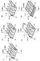
サブタンク36の上部には、サブタンクカバー9に形成された空気孔38によりサブタンク36内と連通する、ゴム等の弾性部材で形成された、サブタンク36内の急激な圧力変化を吸収する圧力調整室8が設けられている。この圧力調整室8を保護するため、圧力調整室8の上部であるカートリッジ3の上面40には、図6(a)に示すように、カートリッジ3の前面42から後面43に向かうY方向に一体的に形成されたリブ15と、このリブ15に対して交差するX方向に一体的に形成された補強リブ14とを有する板部材である化粧フタ7が取り付けられている。この化粧フタ7は、リブ15の端部に突出して形成された係合部39が、カートリッジ3の内壁に上面40側に開いて形成されているテーパ部51によりガイドされ、後述のヘッド基板35に略平行な垂直部52まで滑り込み、この垂直部52で係合部39の両端面がカートリッジ3の内壁に圧接するようにしてはまりこみ、さらに、爪部53がカートリッジ3の係合穴31に係合して取り付けられている。
また、テーパ部51と垂直部52の垂直方向の高さを、リブ15の高さよりも高くするとともにリブ15および補強リブ14はテーパ部51あるいは垂直部52以外では、カートリッジ3のどの部位とも干渉しないように配することにより、化粧フタ7を開口端面76に突き当て固定することができる。このとき、リブ15は、カートリッジ本体の成型等のそりや変形等を矯正する働きを有する。
上記リブ15と、サブタンク36だけでなく、インク溜め21、流路6、液室20を各色毎に仕切る隔壁50とは、カートリッジ3のY方向の剛性を高める機能を有する。また、カートリッジ3の側面方向であるX方向の剛性は、化粧フタ7の補強リブ14およびサブタンクカバー9により確保されている。
化粧フタは図6(b)に示すように、リブ15と補強リブ14の交点が、曲面になっていて、Y方向の剛性を高める構造になっていても良い。また、図6(c)に示すように、交点をC面取り上に補強してY方向の剛性を高める構造としてもよい。さらに図6(d)に示すように、リブ15が中央部にいくほど太くなる形状としてY方向の剛性を高める構造としてもよい。また、図6(e)に示すように、リブ15の端面にリブ状面を設けて、面でカートリッジ3の内壁に圧接するようにしてもよい。また、当然これらの形状を組み合わせて良い。
【0050】
また、隔壁50は、前面42と後面43とを繋ぐように、カートリッジ3本体と一体的に成形されている。さらに、隔壁50の長手方向がキャリッジ1の走査方向と略直交した構成であるため、キャリッジ1の走査時の振動によるサブタンク36内、あるいは液室20内のインクの揺動を最小限に抑制することができる。
【0051】
カートリッジ3の、ニードル受容部23が設けられた後面43の対向面であり、記録装置本体が設置された際、奥面側となる前面42には、ヘッド基板35が取り付けられている。このヘッド基板35には、キャリッジ1の内壁に設けられた複数の電極27(保持手段側電極)に対して押し付けられることで電気的に接続する複数のカートリッジ側電極4を有する電気的コネクト部が設けられている。また、このヘッド基板35は、カートリッジ側電極4が設けられている領域の背面である基板背面33側から、カートリッジ3の前面42に形成された複数の前面リブ44の端面により支持されている。すなわち、ヘッド基板35は、メンバ部材である化粧フタ7のリブ15により、上面40側Y方向の剛性が確保され、かつ、ヘッド基板35に配列されているカートリッジ側電極4の配列領域の、電極27から受ける第1の反力である反力P1(図13参照)の方向の投影面と交差する位置で前面42に接続している隔壁50によりY方向の剛性が確保されたカートリッジ3の前面42に取り付けられている。さらに、ヘッド基板35は、上述したように、基板背面33側から前面リブ44で支持されている。このため、ヘッド基板35は、キャリッジ1に搭載される際に受ける、電極27が押し付けられた際の前面42から後面43に向かうY方向の押圧力に対して、各電極27が各カートリッジ側電極4に略均等な押圧力で電気的に接続されうる平面度が確保されている。本実施形態においては、カートリッジ側電極とのコンタクトによるヘッド前面の変形を防止するためにその部位の肉厚を厚くしている。また一般的に肉厚を厚くすると成型時にいわゆる「ヒケ」が生じる可能性があるため、この部位を図中に示すように「肉抜き」形状としている。
【0052】
さらにコンタクト性を良好に保つために当接部位の平面性が要求される。そのためにもこの当接部位を格子状にすることで平面性が向上する。(図2参照) また、ヘッド基板35は、図7に示すようにフレキシブル基板16によりヒータボード26と電気的に接続されている。なお、図7は、ヘッド基板35がカートリッジ3の前面42に取り付けられる前の状態を示している。
【0053】
カートリッジ3の右側面45および左側面46には、カートリッジ3がキャリッジ1に搭載された際のキャリッジ1に対する位置を決めるための、第1のY方向位置決め部11、第2のY方向位置決め部17、およびZ方向位置決め部13がそれぞれ設けられている。すなわち、電気的なコネクトがなされる前面42、ニードル受容部23とニードル30とが接続されるインクコネクタ部が形成されるインクコネクトの面である後面43、吐出口29が形成されている下面41、および上面40以外の、側面2面である、右側面45および左側面46に全ての位置決め部を設けることにより、側面の構造壁をたわませる方向(側壁に垂直方向)に力が発生せず、構造壁を押しつぶす、力が対向するようにしたことで、各位置決め部の変形を最小に押さえる構造となっている。
【0054】
また、右側面45および左側面46の上端側には、カートリッジ3をキャリッジ1に固定するための加圧力がかかる部位である第1の加圧部12および第2の加圧部19が形成されている。第1の加圧部12は、カートリッジ3がキャリッジ1に搭載された状態で、前面42に対して傾斜しており、一方、第2の加圧部19は前面42に対して略並行となる。これら第1の加圧部12と第2の加圧部19との間には、第1の部材としてのヘッドセット部54(図13参照)が摺動可能な傾斜部18が形成されている。また、第1の加圧部12と傾斜部18との間には、ヘッドセット部54による第1の加圧部12への加圧が保持されるように、ヘッドセット部54を引っ掛けて止める止め部66が形成されている。
【0055】
なお、第1のY方向位置決め部11、第2のY方向位置決め部17、およびZ方向位置決め部13による位置決め、および第1の加圧部12および第2の加圧部19に対する加圧による固定に関しては後述する。
【0056】
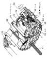
次に、ニードル保持部に関して、図8に示すニードル保持部の一部破断上面図、ヘッドセットレバーと、インクコネクトレバーとが共に閉じた状態のカートリッジの斜視図である図11、およびカートリッジをキャリッジから取り外す際の手順を各工程毎に示した説明図である図15を用いて説明する。
【0057】
ニードル保持部材24には、カートリッジ3の各ニードル受容部23に挿入される複数のニードル30と、ニードル受容部23へのニードル30の挿入をガイドするための、カートリッジ3のボス穴48に挿入されるガイド用ボス47と、これらニードル30およびガイド用ボス47が設けられている面の背面側に、各ニードル30に独立して連通している複数のチューブ受容部75とが設けられている。ニードル保持部材24内部は、ニードル30に対してチューブ28が任意の位置に配置可能なように、ニードル30とチューブ受容部75とを連通させるインク流路が形成されている。また、チューブ受容部75には、一端がメインタンク2に接続されているチューブ28の他端が接続される。
【0058】
この構成により、カートリッジ3に備えられたニードル受容部23へ各色毎の各ニードル30の接続を容易にするとともにチューブ28の屈曲領域を確保して本体サイズの最小化に貢献している。
【0059】
また、ニードル保持部材24は、図15に示すように、インクコネクトレバー22を回動させることでキャリッジ1に設けられているレール62上を摺動可能に取り付けられている。このインクコネクトレバー22の回動とニードル保持部材24との摺動を関連づけるリンク49が、ニードル保持部材24の両端に設けられているピン60に取り付けられる。すなわち、インクコネクトレバー22をCCW方向に回動させる(図15(c)、(b)、(a)の順)ことでニードル30がニードル受容部23に挿入され、CW方向に回動させる(図15(a)、(b)、(c)の順)ことでニードル30がニードル受容部23から引き抜かれる構成となっている。
【0060】
さらに、ニードル保持部材24の上部には、図13に示すように、ヘッドセットレバー25を下方に押し付ける押し付けレバー58(第2の固定手段)が設けられている。この押し付けレバー58は、押し付けばね59(第2の付勢手段)により、押し付けレバー58を上方から下方へと、すなわち、ヘッドセットレバー25を付勢するようになっている。
【0061】
なお、図8には、カートリッジ3のニードル受容部23に挿入されるニードル30が4本設けられている例を示しているが、これに限定されるものではなく、上述した6つのメインタンク2からの6本のチューブ28に対応するため6本設けられているものであってもよい。この場合、当然ながら、各ニードル30に対応するチューブ受容部75も6本となる。
【0062】
次に、図9〜図15を用いて、キャリッジ1にカートリッジ3を搭載する手順を説明する。なお、図9〜図11に示す斜視図には、簡単のため、カートリッジ3は省略している。
【0063】
まず、キャリッジ1に対してのカートリッジ3の位置決めに関して説明する。
【0064】
図9は、カートリッジ3をキャリッジ1に固定するためのヘッドセットレバー25と、ニードル保持部材24を摺動させて、ニードル保持部材24のニードル30をニードル受容部23に挿入するためのインクコネクトレバー22とが開いた状態を示している。この図9の状態は、キャリッジ1にカートリッジ3を搭載する手順を各工程毎に示した図12(a)に相当する。
【0065】
カートリッジ3をキャリッジ1の内部に滑り込ませると、まず、カートリッジ3はキャリッジ1の突出部61がキャリッジ1の底部に突き当たるとともに、ヘッドセットレバー25の支え爪63がカートリッジ3の当接部64に当接する。この状態で、カートリッジ3はキャリッジ1に対して−θXの傾き(図12でCW(時計回り)方向)、すなわち、X軸周りに傾いている。
【0066】
次に、第1の固定手段としてのヘッドセットレバー25をCW方向に回動させると、図12(b)に示すように、カートリッジ3はキャリッジ1の底面近傍のZ方向位置決め部13、第2のY方向位置決め部17および回転中心10がキャリッジ1に接触する。また、ヘッド基板35のカートリッジ側電極4の一部が電極27に接触する。しかし、この時点でも、電極27の反力があるので、カートリッジ3は、図12(b)に示すように、キャリッジ1の内部で、まだ、−θXに傾いている。
【0067】
次に、図12(b)の状態からヘッドセットレバー25をCW方向にさらに回動させると、傾斜部18に対して第1の付勢手段としてのヘッドセットばね57による加圧力P2(第1の加圧力)がかかる。この加圧力P2は、図13に示すように、Y方向の分力P2YおよびZ方向の分力P2Zに分けられる(ただし、図13では、ヘッドセットレバー25は第1の加圧部12に位置している。)。そして、カートリッジ3は、ヘッドセットレバー25をさらに回動させることで生じるY方向の分力P2Yによる回転中心10周りの回転トルク(CCW、θX方向)が、電極27の反力による回転中心10周りの回転トルク(CW、−θX方向)を上回った時、回転中心10周りに回転を開始する。このカートリッジ3の回転運動の際、ヘッドセット部回転中心67を中心に回転可能にヘッドセットレバー25内部に設けられ、ヘッドセットばね57でカートリッジ3方向に付勢されているヘッドセット部57は、カートリッジ3の傾斜部18を加圧しながら傾斜部18上を摺動する。
【0068】
ヘッドセット部57が止め部66を乗り越え、第1の加圧部12の位置に至ることで、ヘッドセット部57は、ヘッドセットばね57による加圧力P2により、傾斜している第1の加圧部12を加圧する。第1の加圧部12も傾斜しているため、ヘッドセットばね57による加圧力P2は、図13に示すように、Y方向の分力P2YおよびZ方向の分力P2Zに分けられる。Z方向の分力P2Zは、カートリッジ3をキャリッジ1の下面41の方向に加圧する。Z方向の分力P2Zでカートリッジ3のZ方向位置決め部13がキャリッジ1の第1の固定部55の上面に押し当てられ、キャリッジ1に対するカートリッジ3のZ方向の位置が決まる。また、Y方向の分力P2Yは、−Y方向に働き、カートリッジ3をθX方向(CCW)に回転させる。
【0069】
カートリッジ3は、Y方向の分力P2Yによる回転中心10周りの回転トルク(CCW、θX方向)がカートリッジ側電極4の反力P1による回転中心10周りの回転トルク(CW、−θX方向)を十分に上回った状態で、θXの回転止めとなる第1のY方向位置決め部11が、キャリッジ1の第2の固定部56に突き当たり、また、第2のY方向位置決め部17が、キャリッジ1の第1の固定部55の側面に押し当てられることで、θX方向に位置を決める。また、第1のY方向位置決め部11は、カートリッジ3の右側面45と左側面46との両側に設けられているため、θX方向の位置が決まると同時に、θZも決まることとなる。なお、電極27から受ける反力P1の方向と、第2の固定部56が第1のY方向位置決め部11に加える力とは、略同一方向である。
【0070】
これでX方向以外は、キャリッジ1に対し、カートリッジ3は位置を決めたこととなるが、本実施形態では、カートリッジ3とキャリッジ1とは、ある程度までガタを詰めることで、概略でX方向に位置を決める構成とした。これはカートリッジ3の位置決めの際に、X、Y、Zの各力関係は、固定される順番に弱くなっていなければならず、十分にこの差が無ければ、位置決めをする際の邪魔になるからである。
【0071】
以上のようにして、キャリッジ1に対するカートリッジ3の位置が決められる。
【0072】
次に、キャリッジ1に対して位置決めされたカートリッジ3に対して作用する補助的な加圧力P3(第2の加圧力)およびニードル保持部材24の摺動によるニードル30のニードル受容部23への挿入の手順に関して説明する。
【0073】
上述の手順により、カートリッジ3をキャリッジ1に対して位置決めしたことで、ヘッドセットレバー25は閉じた状態となるが、インクコネクトレバー22は図10、あるいは図15(c)に示すように、開いた状態にあり、ニードル30とニードル受容部23との位置関係は、図10、図12(c)あるいは図15(c)に示すように離れた状態にある。
【0074】
この開いた状態のインクコネクトレバー22をCCW方向に回動させると、図10に示すように、リンク49によりインクコネクトレバー22と結合されたニードル保持部材24は、レール62上を図12(e)に示す−Y方向に摺動する。そして、まず、ニードル保持部材24のガイド用ボス47が、カートリッジ3のボス穴48に挿入され、次いで、このボス穴48へのガイド用ボス47にガイドされながら、ニードル受容部23へのニードル30の挿入が開始される。このニードル30の挿入の際のニードル30からカートリッジ3が受ける反力(第2の反力)の方向は、カートリッジ3がキャリッジ1の電極27から受ける反力の方向と相反する方向となる。また、これら反力の方向は、吐出口29の配列方向と略並行な方向である。
【0075】
ここで問題となるのは、このニードル30の挿入によりカートリッジ3が受ける反力がユーザの力によるものなので、無理矢理の挿入の場合、かなり極端な力がかかると考えねばならない。しかし、この力は、P2YおよびP3Yと同じ−Y方向である。つまり、−Y方向の力はこれ以上いくらかけてもカートリッジ3の位置決めを狂わせる要因にはならない。またカートリッジ3の抜去時は、当然反対の力がかかるのであるが、ヘッドを外すときであり問題とはならない。
【0076】
図12(e)の状態から、さらに、インクコネクトレバー22をCCW方向に回動させることで、図12(f)に示すように、ニードル30がニードル受容部23に対して完全に挿入される。また、インクコネクトレバー22も図11に示す、閉じた位置に到達する。このインクコネクトレバー22が閉じた位置では、図13に示すように、ニードル保持部材24の、押し付けばね59により付勢される押し付けレバー58がヘッドセットレバー25の押し付け部68を下方に押し付ける。この押し付けにより、ヘッドセットレバー25はCW方向に回動しようとするため、ヘッドセットレバー25の固定補助部材34(第2の部材)がカートリッジ3の第2の加圧部19に押し付けられることとなる。この第2の加圧部19に対してかかる、固定補助部材34による加圧力P3のY方向分力P3Yは、第1のY方向位置決め部11をキャリッジ1の第2の固定部56に当接させるための補助的な力となる。この加圧力P3は補助的な力であり、その大きさは、加圧力P2よりも小さい。
【0077】
以上のように、カートリッジ3を固定するためにP2とP3の二つの力を使用しているのは、装置の小型化を目的としている。従来の技術であれば、P2のみによってカートリッジの固定を完了するのが一般的である。しかし、図14に示すように、カートリッジ3の固定には、回転中心10からの距離L1の位置に、キャリッジ1からカートリッジ3を離間させようとするP1がかかることで発生する回転トルクよりも、支点からの距離L2の位置に、カートリッジ3を固定するためのP2がかかることで発生する回転トルクの方を大きくする必要がある。カートリッジ3を固定するための回転トルクを大きくするためには、P2を大きくすることとL2を大きくすることが考えられるが、P2を大きくした場合、操作力の増大による操作性の悪化、あるいはモールドで形成されたヘッドセットレバー25やヘッドセット部54の応力限界を超えて変形を招くおそれがある。一方、P2を適正値に設定しL2の大きくしようとした場合は、カートリッジ3が大きくなり装置の大型化を招くこととなる。
【0078】
これに対し、本実施形態の場合、P2のみでカートリッジ3を固定するのではなく、補助的な力であるP3を加える構造としたことにより、P2あるいはL2を大きくする必要がない。よって、カートリッジ3の小型化が可能となる。また、ニードル保持部材24、インクコネクトレバー22等からなるニードル保持構造を利用してP3を発生させているため、部品は、押し付けばね59が増えたのみである。
【0079】
以上のようにして固定されたカートリッジ3をキャリッジ1から取り外すには、図15(a)〜図15(c)に示すように、まず、インクコネクトレバー22をCW方向に回動させることで、ニードル保持部材24のニードル30をニードル受容部23から引き抜く。この際、ニードル保持部材24は、レール62上を+Y方向に摺動するが、ニードル保持部材24を−Y方向に付勢するばね37によりキャリッジ1に摺動可能に取り付けられているため、ニードル保持部材24がレール62から脱落することはない。ニードル30がニードル受容部23から引き抜かれ、インクコネクトレバー22が開放状態になった後、ヘッドセットレバー25を図12(c)〜図12(a)に示すように、CCW方向に回動させ、開放状態にすることで、カートリッジ3をキャリッジ1から取り外すことができる状態となる。
【0080】
以上説明したように本実施形態のカートリッジ3は、Y方向の梁となる隔壁50、および化粧フタ7のリブ15によりY方向の剛性を確保しているので、Y方向にかかる、電極27から受ける反力に対してもヘッド基板35の平面度を確保することができ、よって、電極27とカートリッジ側電極4との安定した電気的な接続を得ることができる。
【0081】
また、本実施形態のカートリッジ3は、電極27からの反力を受ける前面42に対向する後面43でニードル30の挿入の際の反力を受ける構成となっている。このため、カートリッジ3がニードル30の挿入の際に受ける反力の方向は、カートリッジ3が電極27から受ける反力の方向と相反する方向、すなわち、カートリッジ3の位置決めの力がかかる−Y方向であるため、ニードル30の挿入によるインクジェット記録ヘッド69の位置決め精度の低下を抑制できる。また、電気コネクト面である前面42とインクコネクト面である後面43とが離れているため、インクがニードル受容部23から漏洩したとしても、電極27やカートリッジ側電極4が漏洩したインクで濡れる危険性を最小限にすることができる。さらに、本発明のカートリッジのリブのを有する板部材は、カートリッジの成型や組み立てにおける変形を矯正する効果もある。
【0082】
さらに、全ての位置決め部が、カートリッジ3の固定のための力、およびこれに伴う電極27からの反力がかかっても、その主面がこれらの力の方向に対して略平行であることによりカートリッジ3の変形を最小限に抑えることができる右側面45および左側面46に設けられているので、カートリッジ3の変形による、インクジェット記録ヘッド69の位置決め精度の低下を抑制できる。
【0083】
また、本実施形態のカートリッジ3は、単に圧力調整室8を保護するだけでなく、リブ15を有することでメンバ部材としての機能を有する化粧フタ7を取り付けているため、カートリッジ3の変形をさらに、効果的に抑制することができる。
【0084】
また、キャリッジ1に対するカートリッジ3の固定に要する力を、一つの手段で一度にかけるのではなく、主となる加圧力P2と、この加圧力P2を補助する加圧力P3とに分けて加えるため、操作力の増大による操作性の悪化、ヘッドセットレバー25やヘッドセット部54の変形、あるいは、装置の大型化といった問題を回避できる。
【0085】
【発明の効果】
以上説明したように、本発明のカートリッジは、カートリッジ側電極と保持手段側電極との電気的な接続により前面にかかる力に対向しながらカートリッジを保持手段に対して位置決めする際、供給手段を接続する力が、前面に対向した面である後面にかかることで位置決めのための力と同方向となる。よって、供給手段を接続する力が、保持手段に対するカートリッジの位置決め精度に悪影響を及ぼすことがなく、高い位置決め精度を確保できる。
【0086】
また、本発明のカートリッジは、前面と後面とを繋ぐ梁となる隔壁、およびリブを有する板部材をカートリッジ本体の上面とすることで、電気的な接続により前面にかかる力に対しても剛性を確保することができる。
【0087】
さらに、本発明のキャリッジは、キャリッジにカートリッジを固定するのに必要な力を、第1の固定手段と、この第1の固定手段を補助する第2の固定手段との2つに分けて印加するため、固定する際、一度に大きな力を必要としない。よって、固定のための操作性が向上するとともに、固定手段が大型化して装置自体が大型化することもない。
【図面の簡単な説明】
【図1】本発明のインクジェット記録装置の一実施形態を示す概略斜視図である。
【図2】本発明の一実施形態であるカートリッジの側断面図である。
【図3】ニードル受容部側からみた本発明の一実施形態であるカートリッジの正面図である。
【図4】本発明の一実施形態であるカートリッジの分解斜視図である。
【図5】化粧フタを外した状態の、本発明の一実施形態のカートリッジの上方からみた斜視図である。
【図6】リブが形成された面からみた、本発明の一実施形態である化粧フタの斜視図である。
【図7】ヘッド基板がカートリッジの前面に取り付けられる前の状態を示した、本発明の一実施形態のカートリッジの斜視図である。
【図8】ニードル保持部の一部破断上面図である。
【図9】ヘッドセットレバーと、インクコネクトレバーとが、共に開いた状態のカートリッジの斜視図である。
【図10】ヘッドセットレバーのみが閉じた状態のカートリッジの斜視図である。
【図11】ヘッドセットレバーと、インクコネクトレバーとが共に閉じた状態のカートリッジの斜視図である。
【図12】キャリッジにカートリッジを搭載する手順を各工程毎に示した説明図である。
【図13】カートリッジにかかる各力および位置決め部を説明するための図である。
【図14】キャリッジからカートリッジへの加圧力P1と、カートリッジからキャリッジへの加圧力P2と、加圧力P2の補助的な加圧力P3とを回転トルクの関係で示した図である。
【図15】カートリッジをキャリッジから取り外す際の手順を各工程毎に示した説明図である。
【図16】従来のインクジェット記録装置の一例のキャリッジ近傍を模式的に示した斜視図である。
【図17】ディスポーザブルタイプの、従来のカートリッジの一例の構成を示す斜視図である。
【図18】図17に示したカートリッジを下方前面側から見た斜視図である。
【図19】大容量インクタンクが記録装置本体側に固定された構成のインクジェット記録装置の一例の概略斜視図である。
【符号の説明】
1 キャリッジ
2 メインタンク
3 カートリッジ
4 カートリッジ側電極
5 フィルタ
6 流路
7 化粧フタ
8 圧力調整室
9 サブタンクカバー
10 回転中心
11 第1のY方向位置決め部
12 第1の加圧部
13 Z方向位置決め部
14 補強リブ
15 リブ
16 フレキシブル基板
17 第2のY方向位置決め部
18 傾斜部
19 第2の加圧部
20 液室
21 インク溜め
22 インクコネクトレバー
23 ニードル受容部
24 ニードル保持部材
25 ヘッドセットレバー
26 ヒータボード
27 電極
28 チューブ
29 吐出口
30 ニードル
31 係合穴
33 基板背面
34 固定補助部材
35 ヘッド基板
36 サブタンク
37 連通部
38 空気孔
39 係合部
40 上面
41 下面
42 前面
43 後面
44 前面リブ
45 右側面
46 左側面
47 ガイド用ボス
48 ボス穴
49 リンク
50 隔壁
51 テーパ部
52 垂直部
53 爪部
54 ヘッドセット部
55 第1の固定部
56 第2の固定部
57 ヘッドセット部
58 押し付けレバー
59 押し付けばね
60 ピン
61 突出部
62 レール
63 支え爪
64 当接部
66 止め部
67 ヘッドセット部回転中心
68 押し付け部
69 インクジェット記録ヘッド
70、71 ガイドシャフト
72 搬送ローラ
73 インク供給ユニット
74 回復ユニット
75 チューブ受容部
76 突き当て部
L1、L2、L3 距離
P1 反力
P2 加圧力
P2Y 分力
P2Z 分力
P3 加圧力
P3Y 分力
S 記録用シート[0001]
BACKGROUND OF THE INVENTION
The present invention relates to a structure for fixing a cartridge to a carriage of an ink jet recording apparatus and a structure of the cartridge.
[0002]
In order to explain the relationship between the fixing point and the fixing force when the cartridge is fixed to the carriage, in this specification, the thrust direction of the guide shaft that guides the carriage is the X direction, and the conveyance direction of the recording medium is the Y direction. The direction perpendicular to the recording medium surface is defined as the Z direction, and the rotation directions around these three axes are defined as θX, θY, and θZ, respectively.
[0003]
Further, in this specification, “electrical connect” refers to a state where electrical connection is made, and “ink connect” refers to the connection between the ink receiving portion of the cartridge and the needle in order to supply ink to the cartridge. It shall be the state where is made.
[0004]
[Prior art]
Ink jet recording technology directly records characters and images by ejecting ink from fine nozzles toward a recording medium (paper, cloth, plastic sheet, etc.). Conventionally, a recording apparatus having such an ink jet recording head is used in a printer as an output terminal of a copying machine, a facsimile, a printer, a word processor, a workstation, or a personal computer, a host computer, an optical disk apparatus, a video apparatus, etc. It is used in these information processing systems as a handy or portable printer provided. In such a conventional ink jet recording apparatus, an ink jet cartridge in which an ink jet recording head and an ink tank are integrated, or an ink cartridge in which the ink tank is further detachable from the cartridge is known. This cartridge is of a disposable type that is fixedly supported by a carriage provided in the ink jet recording apparatus main body so as to be capable of reciprocating scanning, and is detachable from the carriage.
[0005]
FIG. 16 is a perspective view schematically showing the vicinity of a carriage of an example of a conventional inkjet recording apparatus, and FIG. 17 is a perspective view showing the configuration of an example of a conventional disposable cartridge mounted on the carriage. The perspective view which looked at the cartridge shown in 17 from the lower front side is shown in FIG.
[0006]
A
[0007]
The
[0008]
The
[0009]
A
[0010]
The
[0011]
The
[0012]
[Problems to be solved by the invention]
However, in recent years, in order to perform high-quality recording, the number of inks used in color printers has increased, the number of recording elements has increased, and the nozzle length has become longer in order to increase the recording speed. For this reason, the recording surface of the recording head is enlarged, and the area of the head substrate in which the number of pins of the electrical connector is increased corresponding to the increased nozzles is also increased. However, a plate member such as a head substrate becomes difficult to maintain rigidity as its area increases. Also, in order to receive power supply by pressure contact with the electrode of the carriage, if it is suppressed with a reaction force of 490 N per pin, a stable power supply cannot be received unless it is suppressed with a reaction force of about 69 kN at maximum. There are also things.
[0013]
Originally, a rib is provided in the holder to suppress the deformation of the head partition which is the front surface of the head substrate and the holder due to this applied pressure. This rib extends from the bottom surface of the inner wall of the holder toward the head partition. The force that supports the head substrate is small. If the head substrate is small, there is no problem even if the ribs extend only from the bottom surface of the holder, but when the head substrate is larger than the conventional area, naturally the head partition wall to be supported is also widened, It is very difficult to cover a large partition wall area with only ribs from the bottom surface of the head and support the head substrate without deformation.
[0014]
In order to realize a pressure contact force that exceeds the reaction force that the cartridge receives from the electrode of the carriage when the cartridge having the head substrate that requires a large fixing force due to the increase in size is fixed to the carriage. The force applied to the headset lever can be increased, or the headset lever can be enlarged. However, when the force applied to the headset lever is increased, the operability may be deteriorated due to an increase in the operating force, or deformation may be caused beyond the stress limit of the headset lever formed of a mold. On the other hand, if the force applied to the headset lever is set to an appropriate value and the arm portion of the headset lever is lengthened, the cartridge becomes large and the apparatus becomes large. Also, increasing the force applied to the headset lever may increase the deformation of the cartridge and the head substrate.
[0015]
Furthermore, in recent years, the number of nozzles in the ejection section has increased to shorten the recording time, and the length of the nozzles has increased. On the other hand, the amount of ink ejected at a time has become a very small amount of several pl, Mounting accuracy has been required in the order of several tens of microns.
[0016]
This accuracy is determined by the accuracy of the feeding mechanism of the recording medium, the accuracy of the guide shaft of the carriage that reciprocates across the recording medium, the accuracy of the carriage cartridge positioning point, and the accuracy of the cartridge.
[0017]
In particular, the ink landing deviation in the direction about the rotation axis about the vertical axis on the recording medium causes a ruled line deviation or a color deviation in the case of a line printer. Needless to say, accuracy in different directions also contributes to the landing deviation, but the largest cause of this landing deviation is the mounting accuracy of the nozzle in the rotation direction around the recording medium and the vertical axis.
[0018]
In the conventional head, a rotation stop of θX is provided only at one point in the upper center of the electrical connect. This location is the center of the beam when viewed from the main body of the cartridge, and is the most deformed portion. It is disadvantageous to position at the portion where the deformation is the largest, but in the unlikely event, it must be considered that the deformation is beyond the elastic limit.
[0019]
Even today, high-quality printers require parallelism of about 20 microns when the carriage guide shaft receiving portion is used as a measurement standard. However, accuracy is still the limit at present, and it takes time to drive accuracy, it is not stable, management is complicated, and it is extremely difficult to achieve higher accuracy.
[0020]
In addition, high-quality printers are required not only to achieve high-speed recording, but also to be designed with a view to putting them in the field where a large amount of recording is performed. Therefore, in the disposable type as shown in the conventional example, it is disadvantageous in terms of weight to mount a large-capacity ink tank on the movable part. For this reason, it has become necessary to take a form in which a large-capacity ink tank is lowered from the carriage, connected between them by a tube, and ink is supplied from the ink tank to the recording head via this tube. FIG. 19 shows a schematic perspective view of an example of an ink jet recording apparatus having such a configuration in which such a large capacity ink tank is fixed to the recording apparatus main body side. As shown in the drawing, the ink is supplied from a
[0021]
In such a recording apparatus, Japanese Patent Application Laid-Open No. 10-128992 discloses a recording apparatus having a structure in which a tube is connected at the same time when a cartridge is replaced. In the recording apparatus disclosed in this publication, the connection of the tube is completed at the same time as the cartridge is inserted into the carriage. The direction of electrical connection and tube insertion force was different. Further, in the disclosure example of the above-mentioned publication, there is no problem in the rigidity of the cartridge because the cartridge is configured in one row / one color. For example, when six rows of nozzles are mounted on one cartridge, electrical connection and ink While the number of connecting portions increases and the load increases, the span of the rigid wall surface of the member constituting the cartridge becomes long, and it is considered that it is difficult to maintain the rigidity. That is, there is a problem that the mounting accuracy of the cartridge is lowered and the landing accuracy is deteriorated.
[0022]
SUMMARY An advantage of some aspects of the invention is to provide a cartridge with improved rigidity, a carriage that can securely fix the cartridge with a small operation force, a cartridge and a carriage with high positioning accuracy, a recording apparatus, and a recording head.
[0023]
[Means for Solving the Problems]
In order to achieve the above object, the cartridge of the present invention is detachably mounted on a reciprocating holding means of an ink jet recording apparatus that performs recording by ejecting ink onto a recording medium, and the cartridge main body has the above recording medium. A cartridge having a recording head for ejecting ink from a plurality of nozzles formed in parallel on opposite lower surfaces, wherein the cartridge is electrically connected to the front surface of the cartridge body with respect to the holding means side electrode of the holding means Supplying means for supplying ink to the recording head from a main tank installed in the main body of the ink jet recording apparatus on the rear surface opposite to the front surface, provided with an electrical connecting portion in which side electrodes are formed Ink connector part to be connected is providedAnd
The supply means is moved in the direction opposite to the direction of the first reaction force received from the holding means side electrode by pressing and electrically connecting the cartridge side electrode to the holding means side electrode. Receiving the second reaction force that occurs when connecting to the
Stores ink supplied from the supply means, which is divided by a plurality of partition walls that connect the front surface and the rear surface so that the direction substantially the same as the direction of the first reaction force is the longitudinal direction. A plurality of ink holding portions;
At least one of which both ends are press-contacted to the front surface and the rear surface by being fitted into an upper surface facing the lower surface of the cartridge body, which is substantially composed of six surfaces, from the opening on the upper surface side. A plate member on which ribs are formed;
A pressure adjusting chamber that is formed of an elastic member and communicates with an upper portion in each of the ink holding portions and that is disposed between the ink holding member and the plate member.
It is characterized by.
[0024]
The cartridge of the present invention configured as described above is for supplying ink and a front surface to which a reaction force generated when the cartridge side electrode is mechanically pressed and electrically connected to the holding means side electrode of the holding means. Is opposed to a rear surface to which a reaction force from the supply means generated by physically connecting the supply means to the ink connector portion is applied. Therefore, when positioning the cartridge with respect to the holding means while facing the force applied by electrical connection, the force for connecting the supply means is in the same direction as the positioning force. The force applied to the power supply does not weaken the force connecting the supply means. Therefore, the force for connecting the supply means does not adversely affect the positioning accuracy of the cartridge with respect to the holding means.
[0026]
Further, the cartridge of the present invention has a cartridge main body substantially composed of six surfaces on the two surfaces other than the front surface, the rear surface, the lower surface, and the upper surface facing the lower surface, with respect to the holding means. In particular, the two surfaces may be provided with cartridges in which the principal surfaces of the two surfaces are substantially parallel to the direction of the first reaction force. It may be a side surface of the main body.
[0027]
The cartridge body may be formed integrally with each surface other than the upper surface.
[0028]
The cartridge of the present invention may have a plate member that is fitted into an opening provided on the upper surface of the cartridge body and closes the opening on the upper surface of the cartridge body.
[0029]
Also, the cartridge of the present inventionIsEach partition may be formed integrally with the cartridge body.
[0030]
Furthermore, the cartridge of the present invention may have a lattice-like rib structure on the back surface of the cartridge side electrode on the front surface of the cartridge body.Yes.
[0031]
Also, the cartridge of the present inventionIsThe plate member may have a structure in which the plate member abuts and is fixed at the opening end surface, and two rib-shaped surfaces are formed at the end portions where the plate member is pressed and connected to the inner surfaces of the front surface and the rear surface. And at least one rib that intersects and continues to two rib-shaped surfaces may be formed. Further, at least one reinforcing rib may be formed in a direction intersecting with a rib connected by pressure contact or a rib intersecting and continuing to a rib-shaped surface, or the plate member may be pressed. C chamfering or R-approaching at the intersection of ribs and reinforcing ribs that intersect with and connect to ribs connected to each other, and / or the intersection between ribs that intersect and connect rib-shaped surfaces with rib-shaped surfaces It may be what has been done.
[0032]
Furthermore, the cartridge of the present invention isThe reinforcing ribThe center part may be thicker than the end part,The engaging partEach inner wall of the front surface and the rear surfaceBy guidingIt may assist the fitting of the plate member,The front inner wall isIt spreads toward the opening on the upper surface sideHas a taperIt may be a thing. Also,The substantially parallel vertical part by which the said engaging part is press-contacted below the said taper part and the inner wall side of the said rear surface may be formed,Each ribandEach reinforcing rib may be formed integrally with the plate member. Also,The engaging portion may have a surface in which end portions of the ribs are continuous with the ribs.
[0033]
The cartridge of the present invention isThe cartridgeA first pressing force for fixing to the holding means is applied in the front direction for positioning in the front direction.ForceAnd a lower surface for positioning in the lower surface directionPower ofA first pressurizing part received separately and the front directionPositioning toAnd a second pressurizing unit that receives a second pressurizing force to assist, and the first pressurizing unit has a surface inclined with respect to the front surface, and the second pressurizing unit The pressing part may have a surface substantially parallel to the front surface.
[0034]
Furthermore, the cartridge of the present invention may receive the second reaction force direction and the front direction pressing force in substantially the same direction.
[0035]
The carriage of the present invention is a carriage on which the cartridge of the present invention can be detachably mounted,
A first member for applying the first pressing force to the first pressurizing unit; a first biasing unit for biasing the first member toward the lower surface; and the second pressurizing unit. First fixing means having a second member for applying the second pressing force to
By urging the first fixing unit, the second urging unit applies the second pressing force smaller than the first pressing force to the second pressurizing unit by the second member. And a second fixing means having the above.
[0036]
The carriage of the present invention configured as described above applies a first pressing force to the first pressure portion of the cartridge by the first fixing means, and the second pressing force of the cartridge by the second fixing means. The pressure part is configured to apply a second pressure smaller than the first pressure. That is, the force required to fix the cartridge to the carriage can be applied in two parts.
[0037]
The ink jet recording apparatus of the present invention has a transport means for transporting a recording medium, and the ink jet recording apparatus performs recording by discharging ink to the recording medium.
It has the carriage of the present invention.
[0038]
Since the ink jet recording apparatus as described above performs recording with the cartridge of the present invention held on the carriage of the present invention with high positioning accuracy, the landing accuracy of the ink ejected from the recording head of the cartridge to the recording medium is improved. Can be improved.
[0039]
In addition, the recording head of the present invention may eject ink from each nozzle by utilizing film boiling that occurs in the ink by the thermal energy applied by the electrothermal transducer, and the arrangement direction of each nozzle However, it may be substantially parallel to the direction of the reaction force generated when the supply means is connected to the ink connector portion.
[0040]
DETAILED DESCRIPTION OF THE INVENTION
Next, embodiments of the present invention will be described with reference to the drawings.
[0041]
An example of the ink jet recording apparatus of the present embodiment will be described with reference to FIG.
[0042]
The ink jet recording apparatus shown in FIG. 1 has a reciprocating movement (main scanning) of an ink jet recording head 69 (see FIG. 2), and transports a recording sheet S such as general recording paper, special paper, and OHP film at a predetermined pitch (sub-scanning). In the serial type recording, characters, symbols, images, and the like are formed by selectively ejecting ink from the ink jet recording head 69 and adhering it to the recording sheet S in synchronization with these movements. Device.
[0043]
In FIG. 1, a
[0044]
The ink jet recording head 69 has a plurality of nozzle rows for ejecting inks of different colors. A plurality of independent main tanks 2 are detachably attached to the ink supply unit 73 in accordance with the color of ink ejected from the ink jet recording head 69. The ink supply unit 73 and the ink jet recording head 69 are connected to each other by a plurality of
[0045]
The recovery unit 74 is disposed so as to face the ink ejection surface of the ink jet recording head 69 in the non-recording area that is within the reciprocating range of the ink jet recording head 69 and outside the passing range of the recording sheet S. Has been. The recovery unit 74 includes a cap portion for capping the ink discharge surface of the ink jet recording head 69, a suction mechanism for forcibly sucking ink from the ink jet recording head 69 with the ink discharge port surface being capped, and an ink discharge surface. A cleaning blade for wiping off the dirt.
[0046]
In FIG. 1, the serial type ink jet recording apparatus has been described as an example, but the present invention is also applicable to an ink jet recording apparatus in which a line type ink jet recording head in which nozzle rows are provided over the entire width of the recording medium is mounted. The invention is applicable.
[0047]
Next, FIG. 2 is a side sectional view of the cartridge of the present embodiment, FIG. 3 is a front view of the cartridge of the present embodiment viewed from the needle receiving portion side, and FIG. 4 is a perspective exploded view of the cartridge of the present embodiment. FIG. 5 is a perspective view of the cartridge according to the present embodiment in a state where the decorative lid is removed, as seen from above.
[0048]
The shape of the
[0049]
In the upper part of the sub tank 36, a
Further, the height of the tapered portion 51 and the
The
As shown in FIG. 6B, the decorative lid may have a structure in which the intersection of the
[0050]
The partition wall 50 is integrally formed with the main body of the
[0051]
A
[0052]
Furthermore, the flatness of the contact part is required in order to keep the contact property good. Therefore, the flatness is improved by making the abutting portion into a lattice shape. (See FIG. 2) The
[0053]
On the
[0054]
Further, on the upper end side of the
[0055]
Note that the first Y-
[0056]
Next, with respect to the needle holding portion, a partially broken top view of the needle holding portion shown in FIG. 8, FIG. 11 is a perspective view of the cartridge with the headset lever and the ink connect lever both closed, and the cartridge as a carriage. The procedure at the time of detaching from will be described with reference to FIG. 15 which is an explanatory view showing each step.
[0057]
The
[0058]
This configuration facilitates connection of each
[0059]
As shown in FIG. 15, the
[0060]
Further, on the upper part of the
[0061]
FIG. 8 shows an example in which four
[0062]
Next, a procedure for mounting the
[0063]
First, positioning of the
[0064]
FIG. 9 shows a head set
[0065]
When the
[0066]
next,As the first fixing meansWhen the head set
[0067]
Next, when the
[0068]
The head set
[0069]
In the
[0070]
In this embodiment, the position of the
[0071]
As described above, the position of the
[0072]
Next, the auxiliary pressure P3 acting on the
[0073]
By positioning the
[0074]
When the opened ink connect
[0075]
The problem here is that the reaction force received by the
[0076]
By further rotating the ink connect
[0077]
As described above, the use of the two forces P2 and P3 to fix the
[0078]
On the other hand, in the case of this embodiment, it is not necessary to increase P2 or L2 by adopting a structure in which P3 that is an auxiliary force is applied instead of fixing the
[0079]
In order to remove the
[0080]
As described above, the
[0081]
Further, the
[0082]
Furthermore, even if all the positioning portions are applied with a force for fixing the
[0083]
In addition, the
[0084]
In addition, the force required to fix the
[0085]
【The invention's effect】
As described above, the cartridge of the present invention connects the supply means when positioning the cartridge with respect to the holding means while facing the force applied to the front surface by the electrical connection between the cartridge side electrode and the holding means side electrode. When the force to be applied is applied to the rear surface, which is the surface facing the front surface, the same force as the positioning force is obtained. Therefore, the force for connecting the supply means does not adversely affect the positioning accuracy of the cartridge with respect to the holding means, and high positioning accuracy can be ensured.
[0086]
In addition, the cartridge of the present invention has rigidity against a force applied to the front surface due to electrical connection by using a partition plate as a beam connecting the front surface and the rear surface and a plate member having a rib as the upper surface of the cartridge body. Can be secured.
[0087]
Further, in the carriage of the present invention, the force required to fix the cartridge to the carriage is applied to the first fixing means and the second fixing means for assisting the first fixing means. Therefore, a large force is not required at a time when fixing. Therefore, the operability for fixing is improved, and the fixing means is not enlarged and the apparatus itself is not enlarged.
[Brief description of the drawings]
FIG. 1 is a schematic perspective view showing an embodiment of an ink jet recording apparatus of the present invention.
FIG. 2 is a side sectional view of a cartridge according to an embodiment of the present invention.
FIG. 3 is a front view of a cartridge according to an embodiment of the present invention as seen from the needle receiving portion side.
FIG. 4 is an exploded perspective view of a cartridge according to an embodiment of the present invention.
FIG. 5 is a perspective view of a cartridge according to an embodiment of the present invention, as viewed from above, with a makeup lid removed.
FIG. 6 is a perspective view of a decorative lid according to an embodiment of the present invention, as viewed from a surface on which a rib is formed.
FIG. 7 is a perspective view of the cartridge according to the embodiment of the present invention, showing a state before the head substrate is attached to the front surface of the cartridge.
FIG. 8 is a partially broken top view of the needle holding portion.
FIG. 9 is a perspective view of the cartridge in a state in which a headset lever and an ink connect lever are both opened.
FIG. 10 is a perspective view of the cartridge in a state where only the headset lever is closed.
FIG. 11 is a perspective view of the cartridge in a state where both the headset lever and the ink connect lever are closed.
FIG. 12 is an explanatory diagram showing a procedure for mounting a cartridge on a carriage for each step.
FIG. 13 is a diagram for explaining each force applied to the cartridge and a positioning portion.
FIG. 14 is a view showing a pressing force P1 from the carriage to the cartridge, a pressing force P2 from the cartridge to the carriage, and an auxiliary pressing force P3 of the pressing force P2 in relation to rotational torque.
FIG. 15 is an explanatory diagram showing a procedure for removing a cartridge from a carriage for each step.
FIG. 16 is a perspective view schematically showing the vicinity of a carriage of an example of a conventional ink jet recording apparatus.
FIG. 17 is a perspective view showing a configuration of an example of a conventional cartridge of a disposable type.
18 is a perspective view of the cartridge shown in FIG. 17 as viewed from the lower front side.
FIG. 19 is a schematic perspective view of an example of an inkjet recording apparatus having a configuration in which a large-capacity ink tank is fixed to the recording apparatus main body side.
[Explanation of symbols]
1 Carriage
2 Main tank
3 Cartridge
4 Cartridge side electrode
5 Filter
6 Channel
7 Makeup lid
8 Pressure adjustment chamber
9 Sub tank cover
10 Center of rotation
11 1st Y direction positioning part
12 1st pressurizing part
13 Z direction positioning part
14 Reinforcing ribs
15 Ribs
16 Flexible substrate
17 2nd Y direction positioning part
18 Inclined part
19 Second pressurizing part
20 liquid chamber
21 Ink reservoir
22 Ink Connect Lever
23 Needle receiving part
24 Needle holding member
25 Headset lever
26 Heater board
27 electrodes
28 tubes
29 Discharge port
30 needle
31 engagement hole
33 Back of substrate
34 Fixing auxiliary member
35 Head substrate
36 Sub tank
37 communication part
38 Air holes
39 Engagement part
40 Top surface
41 Bottom
42 Front
43 rear
44 Front rib
45 Right side
46 Left side
47 Boss for guide
48 Boss hole
49 links
50 Bulkhead
51 Tapered part
52 Vertical section
53 Nail
54 Headset
55 1st fixing | fixed part
56 Second fixing part
57 Headset
58 Push lever
59 Pressing spring
60 pins
61 Protrusion
62 rails
63 Supporting claws
64 Contact part
66 Stopping part
67 Headset rotation center
68 Pushing part
69 Inkjet recording head
70, 71 Guide shaft
72 Transport roller
73 Ink supply unit
74 Recovery Unit
75 Tube receiving part
76 Butting part
L1, L2, L3 distance
P1 reaction force
P2 pressure
P2Y component force
P2Z component force
P3 pressure
P3Y component force
S Recording sheet
Claims (21)
Translated fromJapanese前記カートリッジ本体の前面に、前記保持手段の保持手段側電極に対して電気的に接続されるカートリッジ側電極が形成されている電気的コネクト部が設けられ、前記前面とは反対側の後面に、前記インクジェット記録装置の本体に設置されたメインタンクから前記記録ヘッドにインクを供給するための供給手段が接続されるインクコネクタ部が設けられており、
前記カートリッジ側電極を前記保持手段側電極に押圧して電気的に接続することで前記保持手段側電極から受ける第1の反力の方向に対して相反する方向に、前記供給手段を前記インクコネクタ部に接続する際に生じる第2の反力を受け、
前記前面と前記後面とを繋ぐ、前記第1の反力の方向と略同一の方向が長手方向となるように形成された複数の隔壁により分割された、前記供給手段から供給されたインクを貯留する、複数のインク保持部と、
実質的に6面で構成される前記カートリッジ本体の前記下面に対向している上面に、前記上面側の開口からはめ込むことで両端が前記前面と前記後面とに圧接して接続される少なくとも1つのリブが形成されている板部材と、
前記各インク保持部内の上部と連通した、弾性部材で形成され、かつ前記インク保持部材と前記板部材との間に配置されている圧力調整室と、を有している
ことを特徴とするカートリッジ。A plurality of nozzles detachably mounted on a reciprocating holding means of an ink jet recording apparatus that performs recording by discharging ink onto a recording medium, and formed in parallel on the lower surface of the cartridge body facing the recording medium In a cartridge having a recording head for discharging ink from
Provided on the front surface of the cartridge body is an electrical connecting portion in which a cartridge side electrode is formed which is electrically connected to the holding means side electrode of the holding means, and on the rear surface opposite to the front surface, An ink connector portion to which a supply means for supplying ink from a main tank installed in a main body of the inkjet recording apparatus to the recording head is connected;
By pressing and electrically connecting the cartridge side electrode to the holding means side electrode, the supply means is placed in a direction opposite to the direction of the first reaction force received from the holding means side electrode. Receiving the second reaction force that occurs when connecting to the
Stores ink supplied from the supply means, which is divided by a plurality of partition walls that connect the front surface and the rear surface so that the direction substantially the same as the direction of the first reaction force is the longitudinal direction. A plurality of ink holding portions;
At least one of which both ends are press-contacted to the front surface and the rear surface by being fitted into an upper surface facing the lower surface of the cartridge body, which is substantially composed of six surfaces, from the opening on the upper surface side. A plate member on which ribs are formed;
A cartridge comprising: a pressure adjusting chamber which is formed of an elastic member and communicates with an upper portion in each of the ink holding portions and which is disposed between the ink holding member and the plate member. .
前記第1の加圧部に前記第1の加圧力を印加する第1の部材、前記第1の部材を前記下面方向に付勢する第1の付勢手段、および前記第2の加圧部に前記第2の加圧力を印加する第2の部材を有する第1の固定手段と、
前記第1の固定手段を付勢することで、前記第1の加圧力よりも小さい前記第2の加圧力を前記第2の部材により前記第2の加圧部に印加させる第2の付勢手段を有する第2の固定手段とを備えたことを特徴とするキャリッジ。A carriage in which the cartridge according to any one of claims 16 to 18 is detachable,
A first member for applying the first pressing force to the first pressurizing unit; a first biasing unit for biasing the first member toward the lower surface; and the second pressurizing unit. First fixing means having a second member for applying the second pressing force to
By urging the first fixing means, a second urging force is applied by the second member to the second pressurizing portion, the second urging force being smaller than the first urging force. And a second fixing means having means.
請求項19に記載のキャリッジを有することを特徴とするインクジェット記録装置。In an inkjet recording apparatus that includes a transport unit that transports the recording medium and performs recording by discharging ink to the recording medium.
An ink jet recording apparatus comprising the carriage according to claim 19.
Priority Applications (4)
| Application Number | Priority Date | Filing Date | Title |
|---|---|---|---|
| JP2002029050AJP4095308B2 (en) | 2001-02-09 | 2002-02-06 | Cartridge, carriage, ink jet recording apparatus and recording head |
| EP02002765AEP1231063B1 (en) | 2001-02-09 | 2002-02-07 | Cartridge, carriage, ink jet recording apparatus, and recording head |
| DE60229575TDE60229575D1 (en) | 2001-02-09 | 2002-02-07 | Cartridge, carriage, ink jet recording device and recording head |
| US10/067,221US6851795B2 (en) | 2001-02-09 | 2002-02-07 | Cartridge with opposed electrical and ink connection portions, and carriage and ink jet recording apparatus for same |
Applications Claiming Priority (3)
| Application Number | Priority Date | Filing Date | Title |
|---|---|---|---|
| JP2001033769 | 2001-02-09 | ||
| JP2001-33769 | 2001-02-09 | ||
| JP2002029050AJP4095308B2 (en) | 2001-02-09 | 2002-02-06 | Cartridge, carriage, ink jet recording apparatus and recording head |
Publications (3)
| Publication Number | Publication Date |
|---|---|
| JP2002307673A JP2002307673A (en) | 2002-10-23 |
| JP2002307673A5 JP2002307673A5 (en) | 2007-08-09 |
| JP4095308B2true JP4095308B2 (en) | 2008-06-04 |
Family
ID=26609201
Family Applications (1)
| Application Number | Title | Priority Date | Filing Date |
|---|---|---|---|
| JP2002029050AExpired - Fee RelatedJP4095308B2 (en) | 2001-02-09 | 2002-02-06 | Cartridge, carriage, ink jet recording apparatus and recording head |
Country Status (4)
| Country | Link |
|---|---|
| US (1) | US6851795B2 (en) |
| EP (1) | EP1231063B1 (en) |
| JP (1) | JP4095308B2 (en) |
| DE (1) | DE60229575D1 (en) |
Families Citing this family (20)
| Publication number | Priority date | Publication date | Assignee | Title |
|---|---|---|---|---|
| JP4086515B2 (en) | 2002-02-15 | 2008-05-14 | キヤノン株式会社 | Seal member, connection structure using the same, and liquid jet recording head |
| US7083272B2 (en)* | 2004-01-21 | 2006-08-01 | Silverbrook Research Pty Ltd | Secure method of refilling an inkjet printer cartridge |
| US7198352B2 (en)* | 2004-01-21 | 2007-04-03 | Kia Silverbrook | Inkjet printer cradle with cartridge stabilizing mechanism |
| US20050157112A1 (en) | 2004-01-21 | 2005-07-21 | Silverbrook Research Pty Ltd | Inkjet printer cradle with shaped recess for receiving a printer cartridge |
| US7448734B2 (en) | 2004-01-21 | 2008-11-11 | Silverbrook Research Pty Ltd | Inkjet printer cartridge with pagewidth printhead |
| JP4678220B2 (en)* | 2005-03-28 | 2011-04-27 | セイコーエプソン株式会社 | Ink cartridge attaching / detaching apparatus, recording apparatus, and liquid ejecting apparatus |
| JP4697434B2 (en) | 2006-02-22 | 2011-06-08 | セイコーエプソン株式会社 | Carriage and recording apparatus including the carriage |
| JP4968437B2 (en)* | 2006-06-12 | 2012-07-04 | セイコーエプソン株式会社 | Carriage and liquid ejecting apparatus |
| JP4823038B2 (en)* | 2006-12-06 | 2011-11-24 | キヤノン株式会社 | Ink jet head cartridge, recording head, ink storage container, and method of manufacturing ink jet head cartridge |
| JP5098738B2 (en)* | 2008-03-25 | 2012-12-12 | セイコーエプソン株式会社 | Liquid injection system and liquid container |
| EP2105307B1 (en)* | 2008-03-25 | 2011-11-16 | Seiko Epson Corporation | LIquid jetting system, liquid container, holder, and liquid jetting apparatus having holder |
| JP2012158169A (en)* | 2011-01-14 | 2012-08-23 | Seiko Epson Corp | Liquid ejecting head unit and liquid ejecting apparatus |
| US8388107B2 (en)* | 2011-04-22 | 2013-03-05 | Hewlett-Packard Development Company, L.P. | Latch for a liquid dispenser |
| JP6012250B2 (en)* | 2012-05-08 | 2016-10-25 | キヤノン株式会社 | Inkjet recording device |
| US9987849B2 (en) | 2015-08-21 | 2018-06-05 | Canon Kabushiki Kaisha | Liquid ejecting device |
| JP7246978B2 (en) | 2019-03-15 | 2023-03-28 | キヤノン株式会社 | Liquid ejection device and liquid filling method |
| JP7391637B2 (en) | 2019-12-03 | 2023-12-05 | キヤノン株式会社 | Liquid storage device and liquid filling method |
| JP7551347B2 (en) | 2020-06-17 | 2024-09-17 | キヤノン株式会社 | Image Recording Device |
| JP7500298B2 (en) | 2020-06-17 | 2024-06-17 | キヤノン株式会社 | Image Recording Device |
| JP7534710B2 (en)* | 2020-11-05 | 2024-08-15 | 株式会社リコー | Liquid ejection device |
Family Cites Families (8)
| Publication number | Priority date | Publication date | Assignee | Title |
|---|---|---|---|---|
| EP0715959B1 (en)* | 1991-12-11 | 1999-06-30 | Canon Kabushiki Kaisha | Ink jet cartridge and ink tank |
| CA2084708C (en) | 1991-12-11 | 1997-11-25 | Hiromitsu Hirabayashi | Ink jet recording apparatus and carriage mechanism therefor |
| US5971529A (en) | 1994-10-31 | 1999-10-26 | Hewlett-Packard Company | Automatic ink interconnect between print cartridge and carriage |
| US6137513A (en)* | 1994-10-31 | 2000-10-24 | Hewlett-Packard Company | Printer using print cartridge with internal pressure regulator |
| US5877795A (en) | 1996-05-24 | 1999-03-02 | Hewlett-Packard Co. | Methods and designs to purge air from ink tubes during initial startup |
| JP2001010081A (en) | 1999-06-30 | 2001-01-16 | Canon Inc | Ink jet cartridge, ink jet device, and method of manufacturing ink jet cartridge |
| US6494630B2 (en)* | 1999-10-31 | 2002-12-17 | Hewlett-Packard Company | Datum structure for compact print cartridge |
| JP3387890B2 (en) | 2000-03-31 | 2003-03-17 | キヤノン株式会社 | Liquid container and recording device |
- 2002
- 2002-02-06JPJP2002029050Apatent/JP4095308B2/ennot_activeExpired - Fee Related
- 2002-02-07USUS10/067,221patent/US6851795B2/ennot_activeExpired - Lifetime
- 2002-02-07EPEP02002765Apatent/EP1231063B1/ennot_activeExpired - Lifetime
- 2002-02-07DEDE60229575Tpatent/DE60229575D1/ennot_activeExpired - Lifetime
Also Published As
| Publication number | Publication date |
|---|---|
| DE60229575D1 (en) | 2008-12-11 |
| EP1231063A3 (en) | 2003-08-06 |
| US20020118263A1 (en) | 2002-08-29 |
| US6851795B2 (en) | 2005-02-08 |
| EP1231063A2 (en) | 2002-08-14 |
| EP1231063B1 (en) | 2008-10-29 |
| JP2002307673A (en) | 2002-10-23 |
Similar Documents
| Publication | Publication Date | Title |
|---|---|---|
| JP4095308B2 (en) | Cartridge, carriage, ink jet recording apparatus and recording head | |
| KR101009859B1 (en) | Inkjet Recording Heads and Inkjet Recording Devices | |
| JPH08290563A (en) | Ink jet recording device | |
| JP2003237107A (en) | Liquid jet recording head and liquid jet recording apparatus | |
| JP2001058418A (en) | Carriage and inkjet recording device | |
| JP2003237070A (en) | Liquid jet recording head | |
| JP3332590B2 (en) | Recording device | |
| JP3234087B2 (en) | Ink jet recording device | |
| JP2875635B2 (en) | INK JET PRINT HEAD, INK JET PRINTING APPARATUS USING THE HEAD, AND METHOD OF CLEANING THE PRINT HEAD OF THE APPARATUS | |
| JP3958063B2 (en) | Liquid jet recording head and recording apparatus | |
| JP2002234179A (en) | Liquid injection device | |
| US20060103690A1 (en) | Inkjet printer | |
| JPH04247942A (en) | Recording head unit, ink tank unit, inkjet head cartridge having these integrated, and inkjet recording device | |
| JPH06199006A (en) | Recording apparatus | |
| JP2875636B2 (en) | Ink jet recording device | |
| JP2875637B2 (en) | Ink jet recording apparatus and method for cleaning recording head used in the apparatus | |
| JP3090965B2 (en) | Ink tank unit, inkjet head cartridge and inkjet recording device | |
| JP3988257B2 (en) | Image forming apparatus and cartridge member | |
| JP2761065B2 (en) | Ink jet recording device | |
| JP2991507B2 (en) | Ink jet recording head cartridge and ink jet recording apparatus using the same | |
| JP2006231770A (en) | Liquid ejection device | |
| JP2006168071A (en) | Ink tank, recording head cartridge, and ink tank mounting method | |
| JP4411787B2 (en) | Print head unit and printer having the same | |
| JP3048651B2 (en) | INK JET PRINT HEAD, PRESS JIG FOR THE PRINT HEAD, AND INK JET PRINTING APPARATUS HAVING THE PRINT HEAD | |
| JP2007007920A (en) | Inkjet recording device |
Legal Events
| Date | Code | Title | Description |
|---|---|---|---|
| A621 | Written request for application examination | Free format text:JAPANESE INTERMEDIATE CODE: A621 Effective date:20050127 | |
| RD03 | Notification of appointment of power of attorney | Free format text:JAPANESE INTERMEDIATE CODE: A7423 Effective date:20050127 | |
| A977 | Report on retrieval | Free format text:JAPANESE INTERMEDIATE CODE: A971007 Effective date:20070301 | |
| A521 | Request for written amendment filed | Free format text:JAPANESE INTERMEDIATE CODE: A523 Effective date:20070625 | |
| A131 | Notification of reasons for refusal | Free format text:JAPANESE INTERMEDIATE CODE: A131 Effective date:20070704 | |
| A521 | Request for written amendment filed | Free format text:JAPANESE INTERMEDIATE CODE: A523 Effective date:20070831 | |
| A131 | Notification of reasons for refusal | Free format text:JAPANESE INTERMEDIATE CODE: A131 Effective date:20071128 | |
| A521 | Request for written amendment filed | Free format text:JAPANESE INTERMEDIATE CODE: A523 Effective date:20080124 | |
| TRDD | Decision of grant or rejection written | ||
| A01 | Written decision to grant a patent or to grant a registration (utility model) | Free format text:JAPANESE INTERMEDIATE CODE: A01 Effective date:20080220 | |
| A61 | First payment of annual fees (during grant procedure) | Free format text:JAPANESE INTERMEDIATE CODE: A61 Effective date:20080307 | |
| FPAY | Renewal fee payment (event date is renewal date of database) | Free format text:PAYMENT UNTIL: 20110314 Year of fee payment:3 | |
| R150 | Certificate of patent or registration of utility model | Free format text:JAPANESE INTERMEDIATE CODE: R150 | |
| FPAY | Renewal fee payment (event date is renewal date of database) | Free format text:PAYMENT UNTIL: 20120314 Year of fee payment:4 | |
| FPAY | Renewal fee payment (event date is renewal date of database) | Free format text:PAYMENT UNTIL: 20130314 Year of fee payment:5 | |
| FPAY | Renewal fee payment (event date is renewal date of database) | Free format text:PAYMENT UNTIL: 20140314 Year of fee payment:6 | |
| LAPS | Cancellation because of no payment of annual fees |