JP4095220B2 - Electronic endoscope system, electronic endoscope apparatus, and signal switching apparatus for electronic endoscope - Google Patents
Electronic endoscope system, electronic endoscope apparatus, and signal switching apparatus for electronic endoscopeDownload PDFInfo
- Publication number
- JP4095220B2 JP4095220B2JP2000016723AJP2000016723AJP4095220B2JP 4095220 B2JP4095220 B2JP 4095220B2JP 2000016723 AJP2000016723 AJP 2000016723AJP 2000016723 AJP2000016723 AJP 2000016723AJP 4095220 B2JP4095220 B2JP 4095220B2
- Authority
- JP
- Japan
- Prior art keywords
- signal
- electronic endoscope
- output
- control circuit
- composite
- Prior art date
- Legal status (The legal status is an assumption and is not a legal conclusion. Google has not performed a legal analysis and makes no representation as to the accuracy of the status listed.)
- Expired - Fee Related
Links
- 230000006854communicationEffects0.000claimsdescription53
- 239000002131composite materialSubstances0.000claimsdescription47
- 230000015572biosynthetic processEffects0.000claimsdescription15
- 238000000926separation methodMethods0.000claimsdescription15
- 238000003786synthesis reactionMethods0.000claimsdescription15
- 230000002093peripheral effectEffects0.000claimsdescription13
- 230000002194synthesizing effectEffects0.000claimsdescription10
- 238000003384imaging methodMethods0.000description20
- 238000005286illuminationMethods0.000description19
- 230000005540biological transmissionEffects0.000description9
- 230000003321amplificationEffects0.000description4
- 238000010586diagramMethods0.000description4
- 238000001914filtrationMethods0.000description4
- 238000003199nucleic acid amplification methodMethods0.000description4
- 230000003287optical effectEffects0.000description3
- 230000006870functionEffects0.000description2
- 239000013307optical fiberSubstances0.000description2
- 230000007175bidirectional communicationEffects0.000description1
- 230000006866deteriorationEffects0.000description1
- 230000000694effectsEffects0.000description1
- 230000005284excitationEffects0.000description1
- 230000004044responseEffects0.000description1
- 230000008054signal transmissionEffects0.000description1
Images


Landscapes
- Instruments For Viewing The Inside Of Hollow Bodies (AREA)
- Endoscopes (AREA)
- Closed-Circuit Television Systems (AREA)
Description
Translated fromJapanese【0001】
【発明の属する技術分野】
本発明は、複数の電子内視鏡装置において、TVモニタやVCR(video cassette recorder )等の周辺機器を共有する電子内視鏡システムと、この電子内視鏡システムにおいて周辺機器へ出力される映像信号を選択的に切換える電子内視鏡用信号切換装置に関する。
【0002】
【従来の技術】
近年医療分野では、RGBモノクロ面順次撮像方式、カラー単板撮像方式等を用いた電子内視鏡システムや、超音波内視鏡システム、励起波長による蛍光画の撮像を行なう電子内視鏡システムなど多様な電子内視鏡システムがその用途に応じて用いられている。これらの電子内視鏡システムにより撮影された映像の観察にはTVモニタ等の画像表示装置が用いられる。
【0003】
各電子内視鏡システムは、その用途、特質が異なるため、総合病院のように複数の電子内視鏡システムを使用する施設も多く存在する。このような施設において、各電子内視鏡システム毎にTVモニタや映像を記録するためのVCR等を設置することは場所的にも設備的にも無駄が多いうえ操作も煩雑である。したがって、各電子内視鏡システムにおいて同一の機能を果たすTVモニタやVCR等の周辺装置に関しては、システム間における共有化を行おうという考えがある。このとき、それぞれの電子内視鏡装置(電子内視鏡と信号処理装置)は、周辺装置へ出力される信号を選択的に切換えるための電子内視鏡用信号切換装置を介して周辺装置に接続される。
【0004】
【発明が解決しようとする課題】
このように複数の電子内視鏡装置とこれらに共有される周辺装置が電子内視鏡用信号切換装置を介して接続される電子内視鏡システムにおいて、各装置の機能・動作を効率よく利用するには、各電子内視鏡装置と電子内視鏡用信号切換装置とを有機的に結合することが望ましい。各電子内視鏡装置と電子内視鏡用信号切換装置とを有機的に結合するには、電子内視鏡用信号切換装置にシステムコントロール回路を設け、このシステムコントロール回路と各電子内視鏡装置のシステムコントロール回路との間で、各装置を制御するための制御信号や各装置の状態などを知らせるためのデータ等を相互に通信する必要がある。
【0005】
一方、各電子内視鏡装置で検出された映像信号を雑音等の影響による劣化を極力抑えて周辺装置へ伝送するには、映像信号をコンポーネント信号として伝送することが好ましい。映像信号をコンポーネント信号として伝送するには、各電子内視鏡装置で検出された映像信号を3原色の色成分毎に送信する必要がある他、これらの映像信号の同期信号も送信する必要があるので合計4本の信号線が必要である。また、上記のように電子内視鏡用信号切換装置に設けられたシステムコントロール回路と各電子内視鏡装置のシステムコントロール回路との間において双方向の通信を行うには、更に通信のための信号線が必要となる。例えば2台の電子内視鏡装置を備えた電子内視鏡システムでは、コンポーネント信号に各4本の信号線が、通信に各2本の信号線が必要なので合計12本の信号線が必要となる。接続される信号線の増加は、装置のセッティングや移動等を行うに当たって極めて煩雑であり、接続される信号線の数を極力減少させることが望まれる。
【0006】
本発明は、複数の電子内視鏡装置が電子内視鏡用信号切換装置を介して周辺装置と接続される電子内視鏡システムであって、各電子内視鏡装置と電子内視鏡用信号切換装置とがより少ない信号線で有機的に結合される電子内視鏡システムと、この電子内視鏡システムにおいて用いられる電子内視鏡装置および電子内視鏡用信号切換装置とを得ることを目的としている。
【0007】
【課題を解決するための手段】
本発明の電子内視鏡システムは、少なくとも1台の電子内視鏡装置と、複数の電子内視鏡装置から入力される信号のうち選択された電子内視鏡装置の信号のみ周辺装置へ出力する電子内視鏡用信号切換装置と、電子内視鏡装置に設けられた第1のシステムコントロール回路から出力される第1の通信データと、電子内視鏡装置において生成され映像信号を含まない複合同期信号とを合成した合成信号を生成する信号合成手段と、合成信号を電子内視鏡装置から電子内視鏡用信号切換装置に伝送することができる合成信号用信号線と、電子内視鏡用信号切換装置に伝送された合成信号を複合同期信号と第1の通信データとに分離する信号分離手段と、信号合成手段と信号分離手段とを駆動して、第1の通信データを合成信号用信号線を介して電子内視鏡用信号切換装置へ送信するとともに、電子内視鏡用信号切換装置に設けられた第2のシステムコントロール回路から出力される第2の通信データを合成信号用信号線を介して電子内視鏡装置が受信するための通信手段とを備えたことを特徴としている。
【0008】
好ましくは複合同期信号は、水平同期信号と垂直同期信号とを複合した同期信号である。
【0009】
信号合成手段は好ましくは、水平同期信号および垂直同期信号が出力されていない期間に第1および第2の通信データの送受信を行い、フィールドが第1または第2のフィールド期間の一方のフィールド期間に対応するときに第1の通信データを送信し、他方のフィールド期間に対応するときに第2の通信データを送信する。
【0010】
通信手段は好ましくは、水平同期信号および垂直同期信号に基づく第1のパルス信号と、フィールドが第1のフィールド期間または第2のフィールド期間であることを表すフィールド信号とに基づいて、各システムコントロール回路の入出力を制御する入出力制御手段を備える。
【0011】
好ましくは前記通信手段は、第1のシステムコントロール回路へ入力される信号を伝送する第1の信号線と第1のシステムコントロール回路から出力される信号を伝送する第2の信号線との間において切換えて第3の信号線に接続するための第1の入出力信号切換手段と、第3の信号線と複合同期信号が出力される第4の信号線との間において合成信号用信号線との接続を切換える合成信号用切換手段と、第2のシステムコントロール回路へ入力される信号を伝送する第5の信号線と第2のシステムコントロール回路から出力される信号を伝送する第6の信号線との間において接続を切換える第2の入出力信号切換手段とを備え、合成信号用切換手段が第1のパルス信号に基づいて制御され、第1および第2の入出力信号切換手段がフィールド信号および第1のパルス信号に基づく第2のパルス信号により制御される。
【0012】
好ましくは第1のパルス信号は、水平同期信号および垂直同期信号が出力されていない期間に出力される。また、このとき第2のパルス信号は、第1のパルス信号のうち第1のフィールド期間または第2のフィールド期間のどちらか一方の期間に出力されるパルス信号である。
【0013】
好ましくは入出力制御手段は、フィールド信号が出力され第1のパルス信号が出力されているときに第2のシステムコントロール回路から第2の通信データを出力することを許可するとともに第1のシステムコントロール回路において第2の通信データの入力を許可し、フィールド信号が出力されていなくて第1のパルス信号が出力されているときに第1のシステムコントロール回路から第1の通信データを出力することを許可するとともに第2のシステムコントロール回路において第1の通信データの入力を許可する。
【0014】
好ましくは、合成信号用切換手段が、第1の信号パルスが出力されているときには合成信号用信号線の接続を第3の信号線に切換え、それ以外のときには合成信号用信号線が第4の信号線に接続されている。このとき、第1の入出力信号切換手段が、第2のパルス信号が出力されているときには第1の信号線に第3の信号線の接続を切換え、それ以外のときには第3の信号線が第2の信号線に接続されている。更に、第1の入出力信号切換手段が、第2のパルス信号が出力されているときには第1の信号線に第3の信号線の接続を切換え、それ以外のときには第3の信号線が第2の信号線に接続されている。
【0015】
好ましくは第1および第2の通信データの極性は、複合同期信号において水平同期信号として出力されるパルスの極性と逆向きに設定される信号である。
【0016】
本発明の電子内視鏡装置は、映像信号を含まない複合同期信号とシステムコントロール回路から出力される通信データとを合成して出力する信号合成出力手段と、複合同期信号を構成する垂直同期信号、水平同期信号と、フィールドが第1または第2のフィールド期間であることを表わすフィールド信号とに基づいてシステムコントロール回路における通信データの入出力を制御する通信制御手段とを備えることを特徴としている。
【0017】
本発明の電子内視鏡用信号切換装置は、複数の電子内視鏡装置から入力される信号のうち選択された電子内視鏡装置の信号のみ周辺装置へ出力可能な電子内視鏡用信号切換装置であって、システムコントロール回路と、各電子内視鏡装置において生成される映像信号を含まない複合同期信号と各電子内視鏡装置に備えられたシステムコントロール回路から出力される通信データとが合成された合成信号を分離する信号分離手段と複合同期信号を構成する垂直同期信号、水平同期信号と、フィールドが第1または第2のフィールド期間であることを表わすフィールド信号とに基づいてシステムコントロール回路における通信データの入出力を制御する通信制御手段とを備えている。
【0018】
【発明の実施の形態】
以下、本発明の実施の形態を図面を参照して説明する。
図1は本発明の実施形態である電子内視鏡用信号切換装置(信号切換装置)および電子内視鏡装置(電子内視鏡と信号処理装置)からなる電子内視鏡システムの回路構成を示すブロック図である。
【0019】
信号切換装置10には、RGB面順次撮像方式の信号処理装置40、カラー単板撮像方式の信号処理装置60と、これらに共有されるTVモニタ25とVCR26とがコネクタ(図示せず)を介して着脱自在に接続されている。RGB面順次撮像方式の信号処理装置40には、RGB面順次撮像方式に適合した電子内視鏡30が接続され、カラー単板撮像方式の信号処理装置60には、カラー単板撮像方式に適合した電子内視鏡50が接続される。電子内視鏡30、50と信号処理装置40、60との接続は、それぞれスコープコネクタ(図示せず)を介して着脱自在に行われる。TVモニタ25には、電子内視鏡30で撮像された映像または電子内視鏡50で撮像された映像のうちの一方が表示される。このときTVモニタ25に表示される映像は信号切換装置10または各信号処理装置40、60の操作パネル16、44、64に配されたスイッチ(図示せず)を操作することにより切換え可能である。また、TVモニタ25に表示される映像は、同時にVCR26に送られ、ビデオカセットテープに記録可能である。
【0020】
まず、電子内視鏡30と信号処理装置40からなるRGB面順次撮像方式の電子内視鏡装置について説明する。
【0021】
電子内視鏡30の内部には超極細の光ファイバーケーブルの束であるライトガイド34が配設されており、ライトガイド34の一方の端面である出射端32は電子内視鏡30の先端部に位置している。出射端32の前方には照明レンズ(図示せず)が配されており、出射端32から出射される光が照明レンズを介して照明光として照射される。この照明光は信号処理装置40内に設けられたランプ(光源)37からライトガイド34を介して供給される。
【0022】
ランプ37からは略平行に白色光が照射され、集光レンズ36、RGB回転フィルタ38を介してライトガイド34の入射端35に集光される。これにより入射端35に入射した光はライトガイド34を経由して出射端32に伝送され内視鏡30の先端(出射端32)から照明光として照射される。
【0023】
RGB回転フィルタ38は薄い回転円盤であり、その盤面には円周方向に沿って略等間隔に3つの開口が形成され、各開口には、それぞれ赤(R)、緑(G)、青(B)のカラーフィルタが設けられている。RGB回転フィルタ38はモータ39により回転され、その回転軸はランプ37から照射される照明光の光軸に平行であり、円盤が回転する際に各開口が照明光の光路を横切るように配置されている。すなわち、集光レンズ36を透過した白色照明光は、RGB回転フィルタ38が回転し、各開口が照明光の光路を横切るときにRGBのカラーフィルタをそれぞれ透過して入射端35に集光される。RGBのカラーフィルタを透過した照明光はRGBの光として順次間欠的にライトガイド34に入射される。したがって、電子内視鏡30の先端(出射端32)からは、RGBの光が各色成分毎に順次間欠的に照明光として照射される。
【0024】
ランプ37は、ランプ電源回路46によりその出力が制御され、ランプ電源回路46は、システムコントロール回路43により制御される。システムコントロール回路43から出力される制御信号はデジタル信号でありD/A変換器45でアナログ信号変換されランプ電源回路46へ出力される。モータ39の回転は、タイミングコントロール回路42の同期信号に基づいて制御される。
【0025】
電子内視鏡30の先端には、撮像素子31が設けられておりライトガイド34の出射端32から照射されるRGBの照明光により撮像が行われる。照明光はRGBの各色成分毎に順次間欠的に照射されるので、撮像素子31でもRGBの色成分毎の映像が順次モノクロ映像として検出される。検出されたRGB毎の映像は、時系列のRGB映像信号として電子内視鏡30内のケーブル33を介して信号処理装置40の映像信号処理回路41へ伝送される。
【0026】
映像信号処理回路41に入力された映像信号は、適度に増幅され、映像帯域のフィルタリング処理、S/H処理、増幅処理、クランプ処理、クリップ処理、ガンマ処理等の前段信号処理が施された後デジタルの画像信号に変換される。デジタルの画像信号はRGB毎に一時的に画像メモリ(図示せず)に記憶される。RGBの画像信号が1組揃うと再びアナログ信号に変換されて後段信号処理が行われる。後段信号処理では、フィルタリング処理、増幅処理、ガンマ処理、クランプ処理、クリップ処理、エンハンス処理、レベル調整等が行われ、規格化されたRGBコンポーネント映像信号に変換され映像信号処理回路41から出力される。映像信号処理回路41から出力されたRGBコンポーネント映像信号R1、G1、B1は、コネクタ48に接続されたケーブル49を介して信号切換装置10へ出力される。
【0027】
タイミングコントロール回路42からは、複合同期信号(同期信号)S1が信号合成回路47に出力される。システムコントロール回路43と信号切換装置10との間では、コントロール信号D1の送受信が行われる。コントロール信号D1は、信号処理装置40と信号切換装置10とが、その状態に合わせて相互に通信する制御信号などの通信データである。システムコントロール回路から出力されるコントロール信号D1は、信号合成回路47を介して信号切換装置10へ送信される。また、信号切換装置10から出力されるコントロール信号D1は信号合成回路47を介してシステムコントロール回路43へ入力される。このときシステムコントロール回路43におけるコントロール信号の入出力のタイミングは、タイミングコントロール回路42からのフィールド信号に基づいて制御される。
【0028】
信号合成回路47では、入力された同期信号S1およびコントロール信号D1の合成が行われるとともに、コントロール信号D1の送受信を行うための伝送経路の切換等が行われる。同期信号S1とコントロール信号D1とを合成した合成信号C1は、コネクタ48に接続されたケーブル49を介して信号切換装置10へ出力される。なお、図1においてケーブル49は模式的に1本の太線で描かれているが、RGBコンポーネント映像信号R1、G1、B1を送信するための3本の信号線と合成信号C1を送信するための1本の信号線とを備えている。
【0029】
映像信号処理回路41内の信号処理や撮像素子31の駆動のタイミング(不図示)は、タイミングコントロール回路42の同期信号に基づいて行われる。タイミングコントロール回路42は、システムコントロール回路43により制御される。システムコントロール回路43には、操作パネル44が接続されており、操作パネル44には、スイッチ群(図示せず)が設けられている。
【0030】
次に電子内視鏡50と信号処理装置60からなるカラー単板撮像方式の電子内視鏡装置について説明する。
【0031】
電子内視鏡50の内部には超極細の光ファイバーケーブルの束であるライトガイド54が配設されており、ライトガイド54一方の端面である出射端52は電子内視鏡50の先端部に位置している。出射端52の前方には照明レンズ(図示せず)が配されており、出射端52から出射される光が照明レンズを介して照明光として照射される。この照明光は信号処理装置60内に設けられたランプ(光源)57からスコープコネクタにおいて接続されたライトガイド54を介して供給される。ランプ57からは略平行に白色光が照射され、集光レンズ56等を介してライトガイド54の入射端55に集光される。これにより入射端55に入射した光はライトガイド54を経由して出射端52へ伝送され内視鏡50の先端(出射端52)から照明光として照射される。
【0032】
ランプ57は、ランプ電源回路66によりその出力が制御され、ランプ電源回路66は、システムコントロール回路63により制御される。システムコントロール回路63から出力される制御信号はデジタル信号でありD/A変換器65でアナログ信号変換されランプ電源回路66へ出力される。
【0033】
電子内視鏡50の先端には、撮像素子51が設けられておりライトガイド54の出射端52から照射される白色照明光により撮像が行われる。撮像素子51では、RGB毎の映像が同時に検出され、電子内視鏡50内に設けられたケーブル53を介して、信号処理装置60の映像信号処理回路61へ伝送される。
【0034】
映像信号処理回路61に入力された映像信号は、適度に増幅され、映像帯域のフィルタリング処理、S/H処理、増幅処理、クランプ処理、クリップ処理、ガンマ処理等の前段信号処理が施された後デジタルの画像信号に変換される。デジタルの画像信号はRGB毎に一時的に画像メモリ(図示せず)に記憶される。RGBの画像信号が1組揃うと再びアナログ信号に変換されて後段信号処理が行われる。後段信号処理では、フィルタリング処理、増幅処理、ガンマ処理、クランプ処理、クリップ処理、エンハンス処理、レベル調整等が行われ、規格化されたRGBコンポーネント映像信号に変換され映像信号処理回路61から出力される。映像信号処理回路61から出力されたRGBコンポーネント映像信号R2、G2、B2は、コネクタ68に接続されたケーブル69を介して信号切換装置10へ出力される。
【0035】
タイミングコントロール回路62からは、複合同期信号(同期信号)S2が信号合成回路67へ出力される。システムコントロール回路63と信号切換装置10との間では、コントロール信号D2の送受信が行われる。コントロール信号D2は、信号処理装置60と信号切換装置10とが、その状態に合わせて相互に通信する制御信号などの通信データである。システムコントロール回路63から出力されるコントロール信号D2は、信号合成回路67を介して信号切換装置10へ送信される。また、信号切換装置10から出力されるコントロール信号D2は信号合成回路67を介してシステムコントロール回路63へ入力される。システムコントロール回路63におけるコントロール信号D2の入出力のタイミングは、タイミングコントロール回路62からのフィールド信号に基づいて制御される。
【0036】
信号合成回路67では、入力された同期信号S2およびコントロール信号D2の合成が行われるとともに、コントロール信号D2の送受信を行うための伝送経路の切換等が行われる。同期信号S2とコントロール信号D2とを合成した合成信号C2は、コネクタ68に接続されたケーブル69を介して信号切換装置10へ出力される。なお、図1においてケーブル69は模式的に1本の太線で描かれているが、RGBコンポーネント映像信号R2、G2、B2を送信するための3本の信号線と合成信号C2を送信するための1本の信号線とを備えている。
【0037】
映像信号処理回路61内の信号処理や撮像素子51の駆動のタイミング(不図示)は、タイミングコントロール回路62の同期信号に基づいて行われる。タイミングコントロール回路62は、システムコントロール回路63により制御される。システムコントロール回路63には、操作パネル64が接続されており、操作パネル64には、スイッチ群(図示せず)が設けられている。
【0038】
次に、信号切換装置10の構成について説明する。
ケーブル49およびケーブル69はそれぞれコネクタ19、20を介して信号切換装置10に接続され、ケーブル49、69を伝送された信号はそれぞて信号分離回路17、18へ入力される。RGBコンポーネント映像信号は、信号分離回路17、18を経て切換スイッチ11、12、13へそれぞれ出力される。すなわち、切換スイッチ11にはR1、R2のコンポーネント映像信号が入力され、切換スイッチ12にはG1、G2、切換スイッチ13にはB1、B2のコンポーネント映像信号がそれぞれ入力される。合成信号C1、C2は各々信号分離回路17、18において同期信号S1、S2およびコントロール信号D1、D2に分離される。信号分離回路17、18において分離された同期信号S1、S2はそれぞれ切換スイッチ14へ出力され、コントロール信号D1、D2は、システムコントロール回路15へ出力される。
【0039】
一方、システムコントロール回路15から信号処理装置40、60へ出力されるコントロール信号D1、D2は、信号分離回路17、18、ケーブル49、69、信号合成回路47、67を介してシステムコントロール回路43、63にそれぞれ入力される。なお、このときコントロール信号D1、D2は同期信号と合成されることなくシステムコントロール回路43、63へ送信される。
【0040】
切換スイッチ11〜14は、例えば従来公知のアナログスイッチやリレースイッチ等であり、入力された複数の信号(本実施実施形態では2つの信号)の中から1つの信号を選択して出力する装置である。切換スイッチ11〜14により選択されたRGBコンポーネント映像信号および同期信号は、ケーブルを介してTVモニタ25やVCR26に出力される。すなわち、TVモニタ25やVCR26には、信号処理装置40のコンポーネント信号(R1、G1、B1、S1)または信号処理装置60のコンポーネント信号(R2、G2、B2、S2)の一方がその選択にしたがって出力される。
【0041】
切換スイッチ11〜14における切換動作は、システムコントロール回路15からの信号指令に基づいて実行され、これらの切換動作は切換スイッチ11〜14において同時に行われる。システムコントロール回路15には操作パネル16が接続されており、操作パネル16にはスイッチ群(図示せず)が設けられている。オペレータは例えば操作パネル16に設けられたスイッチ群の中の切換ボタン(図示せず)を押下することにより、切換スイッチ11〜14における切換動作を操作できる。また、切換スイッチ11〜14における切換動作は、信号処理装置40、60のシステムコントロール回路43、63から出力されたコントロール信号D1、D2に基づいても実行可能である。例えば、信号処理装置60のコンポーネント信号が選択されているときに、信号処理装置40の操作パネル44が操作されると、切換スイッチ11〜14の選択を信号処理装置40のコンポーネント信号へ切換えるコントロール信号がシステムコントロール回路43から信号切換装置10のシステムコントロール回路15へ出力される。システムコントロール回路15は、このコントロール信号に対応して切換スイッチ11〜14の選択を切換える。
【0042】
次に図2〜図4を参照して信号合成回路47、67および信号分離回路17、18における信号の合成および分離について説明する。また、システムコントロール回路15、43、63におけるコントロール信号の入出力のタイミングについても説明する。
【0043】
図2は、コントロール信号の通信に関わる回路構成のみを抜き出したブロック図である。信号処理装置60は、信号処理装置40と同様の方法で信号切換装置10とコントロール信号の通信を行うので、以下の説明では信号処理装置40と信号切換装置10との間における通信を例に説明を行う。
【0044】
図面左側の各ブロックは信号処理装置40に関するものであり、図面右側の各ブロックは信号切換装置10に関するものである。ブロック200〜240は信号合成回路47内の回路構成を示しており、ブロック100〜140は信号分離回路17内の回路構成を示している。信号処理装置40の回路はケーブル(合成信号用信号線)49cを介して信号切換装置10の回路に接続されている。
【0045】
タイミングコントロール回路42からは同期信号(SYNC)が信号処理回路200へ出力される。同期信号は従来公知の複合同期信号(図3参照)である。信号処理回路200では、同期信号の信号レベルが送信に適合する信号レベル0〜Vs(例えばVsは8ボルト)に変換され切換回路230へ同期信号e(図4参照)として出力される。また、タイミングコントロール回路42からは、フィールドパルス信号FLD(図3、図4参照)およびパルス信号(第1のパルス信号)b(図3参照)がシステムコントロール回路43へ出力される。これらは、システムコントロール回路43でのコントロール信号の入出力のタイミングを制御するための信号である。
【0046】
システムコントロール回路43から出力されたコントロール信号fは、信号処理回路210においてTTLレベルから通信のための信号レベル(Vs〜Vdボルト)に変換されコントロール信号g(図4参照)として切換回路240を介して切換回路230へ出力される。切換回路230では、コントロール信号gは、同期信号eと合成され合成信号として信号切換装置10へ出力される。
【0047】
一方、信号切換装置10から送信されてくるコントロール信号i(図4参照)は、切換回路230、切換回路240を経て信号処理回路220へ出力される。信号処理回路220では、コントロール信号iが通信のための信号レベルからTTLレベルの信号に変換され、コントロール信号hとしてシステムコントロール回路43へ出力される。
【0048】
切換回路230、240における伝送経路の切換は、それぞれタイミングコントロール回路42から出力されるパルス信号bおよびパルス信号(第2のパルス信号)o(図3参照)によって制御される。切換回路230では、信号線(第4の信号線)80と信号線(第3の信号線)81との間においてケーブル49cと接続される信号線をパルス信号bにしたがって切換え、切換回路240では、信号線(第2の信号線)82と信号線(第1の信号線)83との間において信号線81と接続される信号線をパルス信号oにしたがって切換える。
【0049】
信号処理装置40の切換回路230から出力された同期信号eとコントロール信号gとの合成信号は、ケーブル49cを介して信号切換装置10の切換回路110に入力され、その後同期分離回路120および信号処理回路130へ出力される。信号処理回路130では、入力された合成信号をコントロール信号fに変換した後システムコントロール回路15へ出力する。一方、同期分離回路120では、合成信号から同期信号eが分離されTTLの信号レベルへ変換された後、タイミング回路140へ出力される。タイミング回路140は、入力された同期信号に同期するとともに、入力された同期信号からタイミングコントロール回路42と同様なパルス信号o、パルス信号b、フィールドパルス信号FLDを生成し出力する。パルス信号oは、切換回路110へ出力され、切換回路110での伝送経路の切換を制御する。また、パルス信号bおよびフィールドパルス信号FLDは、システムコントロール回路15に出力され、システムコントロール回路15におけるコントロール信号の入出力のタイミングを制御する。なお同期分離回路120から出力された同期信号eは切換回路14へも出力される。
【0050】
システムコントロール回路15から出力されるコントロール信号hは、信号処理回路100において、TTLレベルの信号から通信のための信号レベルに変換され、コントロール信号iとして切換回路110へ出力される。その後コントロール信号hは、ケーブル49cを介して信号処理装置40へ送信される。なお、切換回路110はパルス信号oにしたがって、信号線(第5の信号線)90と信号線(第6の信号線)91との間においてケーブル49cと接続される信号線を切換える。
【0051】
以上は、信号処理装置40と信号切換装置10との間におけるコントロール信号の送受信についての説明であるが、信号処理装置60と信号切換装置10との間におけるコントロール信号の送受信についても同様である。
【0052】
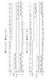
図3(a)、(b)は複合同期信号(SYNC)及びこれに対応した水平同期信号HD、垂直同期信号VDと、フィールドパルス信号FLD、パルス信号b、パルス信号oとの関係を示すタイミングチャートである。図3(a)は第1フィールドが開始する部分を示しており、図3(b)は第1フィールドが終了する部分を示している。
【0053】
水平同期信号HD、垂直同期信号VD、同期信号SYNCは、信号が立ち下がった部分が信号部分である。すなわち、垂直同期信号VDが立ち下がっている区間がT0が垂直帰線消去期間に対応する。フィールドパルス信号は、信号レベルが高いときが第1フィールドに対応しており、信号レベルが低いときが第2フィールドに対応している。パルス信号bは垂直帰線期間T0以外の区間で、水平同期信号HDが立ち下がっていないときに出力される。また、パルス信号oは、パルス信号bを第1フィールドの期間だけ出力したものである。
【0054】
システムコントロール回路43では、フィールドパルス信号FLDの信号レベルが低く(第2フィールド)、パルス信号bの信号レベルが高いとき、すなわちパルスP1が送信されるときにコントロール信号の出力が可能となり、フィールドパルス信号FLDの信号レベルが高く(第1フィールド)、パルス信号bの信号レベルも高いとき、すなわちパルスP2が出力されるときにコントロール信号の受信が可能となる。
【0055】
切換回路240での切換動作は、パルス信号oの信号レベルが高いとき、すなわちパルスP3が出力されている間は信号線83が選択され、それ以外のときに信号線82が選択されるように行われる。切換回路230での切換動作は、パルスP1、P2が出力されている間、信号線81がケーブル49cと接続され、それ以外のときに信号線80に接続されるように行われる。
【0056】
一方、システムコントロール回路15では、フィールドパルス信号FLDの信号レベルが高く(第1フィールド)、パルス信号bの信号レベルも高いとき、すなわちパルスP2が送信されるときにコントロール信号の出力が可能となり、フィールドパルス信号FLDの信号レベルが低く(第2フィールド)、パルス信号bの信号レベルが高いとき、すなわちパルスP1が出力されるときにコントロール信号の受信が可能となる。また、切換回路110では、パルスP3が出力されている間、ケーブル49cが信号線91に接続され、それ以外のときにケーブル49cが信号線90に接続されるように伝送経路の切換えが行われる。
【0057】
図4(a)、(b)は、同期信号e、フィールド信号FLD、信号処理装置40から出力されるコントロール信号g、信号切換装置10から出力されるコントロール信号iおよびケーブル49cを介して送受信される信号kのタイミングチャートである。図3(a)、(b)と同様に第1フィールドの開始部分と第1フィールドの終了部分とがそれぞれ示されている。信号kに示されるように、コントロール信号g、iは、同期信号eの2つの水平同期信号が出力される合間に信号レベルVs〜Vdの信号として出力される。
【0058】
以上により、本実施形態によれば、より少ない信号線でRGBコンポーネント映像信号と通信データとを電子内視鏡装置と電子内視鏡用信号切換装置(信号切換装置)との間において送信できる電子内視鏡システム及びこの電子内視鏡システムで用いられる電子内視鏡装置と電子内視鏡用信号切換装置とが得られる。
【0059】
本実施形態で用いられた電子内視鏡装置の撮像方式は、RGB面順次撮像方式とカラー単板撮像方式であったが、これら以外の撮像方式であってもよい。また本実施形態では、2つの電子内視鏡装置が電子内視鏡用信号切換装置(信号切換装置)に接続されていたが、接続される電子内視鏡装置は3以上であってもよい。
【0060】
本実施形態では、RGBコンポーネント映像信号と複合同期信号とを用いて映像信号を伝送したが、複合同期信号と映像信号とが複合されずに伝送される信号伝送方式であれば他の信号伝送方式であってもよい。
【0061】
【発明の効果】
以上により本発明によれば、複数の電子内視鏡装置が電子内視鏡用信号切換装置を介して周辺装置と接続される電子内視鏡システムであって、各電子内視鏡装置と電子内視鏡用信号切換装置とがより少ない信号線で有機的に結合される電子内視鏡システムと、この電子内視鏡システムにおいて用いられる電子内視鏡装置および電子内視鏡用信号切換装置とを得ることができる。
【図面の簡単な説明】
【図1】本発明の第1の実施形態である電子内視鏡システムの回路構成を示すブロック図である。
【図2】図1に示されたブロック図において、コントロール信号の送受信に関わる部分をより詳しく示した電子内視鏡システムの回路構成を示すブロック図である。
【図3】垂直同期信号VD、水平同期信号HD、フィールドパルス信号FLD等が複合された複合同期信号SYNCとパルス信号b、パルス信号oとの関係を示すタイミングチャートである。
【図4】複合同期信号SYNC、コントロール信号、合成信号との関係を示すタイミングチャートである。
【符号の説明】
10 電子内視鏡用信号切換装置(信号切換装置)
15 システムコントロール回路
40 RGB面順次撮像方式の信号処理装置
49c ケーブル(合成信号用信号線)
60 カラー単板撮像方式の信号処理装置
43、63 システムコントロール回路
SYNC 複合同期信号(同期信号)[0001]
BACKGROUND OF THE INVENTION
The present invention relates to an electronic endoscope system that shares a peripheral device such as a TV monitor or a VCR (video cassette recorder) in a plurality of electronic endoscope apparatuses, and an image output to the peripheral device in this electronic endoscope system. The present invention relates to a signal switching device for an electronic endoscope that selectively switches signals.
[0002]
[Prior art]
In recent years, in the medical field, an electronic endoscope system using an RGB monochrome plane sequential imaging method, a color single-plate imaging method, an ultrasonic endoscope system, an electronic endoscope system that captures a fluorescent image by an excitation wavelength, etc. Various electronic endoscope systems are used depending on the application. An image display device such as a TV monitor is used for observing images taken by these electronic endoscope systems.
[0003]
Since each electronic endoscope system has different uses and characteristics, there are many facilities that use a plurality of electronic endoscope systems such as general hospitals. In such a facility, installing a TV monitor, a VCR for recording video, etc. for each electronic endoscope system is wasteful both in terms of location and equipment and is complicated to operate. Therefore, there is an idea that the peripheral devices such as a TV monitor and a VCR that perform the same function in each electronic endoscope system should be shared among the systems. At this time, each electronic endoscope device (electronic endoscope and signal processing device) is connected to the peripheral device via a signal switching device for electronic endoscope for selectively switching a signal output to the peripheral device. Connected.
[0004]
[Problems to be solved by the invention]
Thus, in an electronic endoscope system in which a plurality of electronic endoscope devices and peripheral devices shared by them are connected via an electronic endoscope signal switching device, the functions and operations of each device are efficiently used. For this purpose, it is desirable to organically couple each electronic endoscope apparatus and the signal switching apparatus for electronic endoscope. In order to organically connect each electronic endoscope apparatus and the electronic endoscope signal switching device, a system control circuit is provided in the electronic endoscope signal switching device, and the system control circuit and each electronic endoscope are provided. It is necessary to communicate with each other a control signal for controlling each device, data for notifying the state of each device, and the like with the system control circuit of the device.
[0005]
On the other hand, in order to transmit a video signal detected by each electronic endoscope apparatus to a peripheral apparatus while suppressing deterioration due to the influence of noise or the like as much as possible, it is preferable to transmit the video signal as a component signal. In order to transmit the video signal as a component signal, it is necessary to transmit the video signal detected by each electronic endoscope apparatus for each of the three primary color components, and also to transmit a synchronization signal of these video signals. Therefore, a total of four signal lines are required. Further, in order to perform bidirectional communication between the system control circuit provided in the electronic endoscope signal switching device and the system control circuit of each electronic endoscope device as described above, further communication is required. A signal line is required. For example, in an electronic endoscope system including two electronic endoscope apparatuses, four signal lines are required for component signals and two signal lines are required for communication, so a total of 12 signal lines are required. Become. The increase in the number of signal lines to be connected is extremely complicated in setting and moving the apparatus, and it is desired to reduce the number of signal lines to be connected as much as possible.
[0006]
The present invention is an electronic endoscope system in which a plurality of electronic endoscope devices are connected to peripheral devices via an electronic endoscope signal switching device, and each electronic endoscope device and electronic endoscope device An electronic endoscope system in which a signal switching device is organically coupled with fewer signal lines, and an electronic endoscope device and an electronic endoscope signal switching device used in the electronic endoscope system are obtained. It is an object.
[0007]
[Means for Solving the Problems]
The electronic endoscope system of the present invention outputs at least one electronic endoscope apparatus and a signal of an electronic endoscope apparatus selected from signals input from a plurality of electronic endoscope apparatuses to peripheral devices. The electronic endoscope signal switching device, the first communication data output from the first system control circuit provided in the electronic endoscope device, and the video signal generated in the electronic endoscope device are not included. A signal synthesizing unit that generates a synthesized signal obtained by synthesizing the composite synchronization signal; a signal line for synthesized signal capable of transmitting the synthesized signal from the electronic endoscope apparatus to the signal switching apparatus for electronic endoscope; and electronic endoscope The first communication data is synthesized by driving the signal separation means for separating the composite signal transmitted to the mirror signal switching device into the composite synchronization signal and the first communication data, the signal synthesis means and the signal separation means. Via the signal line for signal The second communication data transmitted from the second system control circuit provided in the electronic endoscope signal switching device is transmitted to the endoscope signal switching device via the composite signal signal line. The endoscope apparatus includes a communication means for receiving.
[0008]
Preferably, the composite synchronization signal is a synchronization signal obtained by combining a horizontal synchronization signal and a vertical synchronization signal.
[0009]
Preferably, the signal synthesizing unit transmits and receives the first and second communication data during a period in which the horizontal synchronization signal and the vertical synchronization signal are not output, and the field is in one field period of the first or second field period. The first communication data is transmitted when corresponding, and the second communication data is transmitted when corresponding to the other field period.
[0010]
The communication means preferably controls each system control based on the first pulse signal based on the horizontal synchronization signal and the vertical synchronization signal and the field signal indicating that the field is the first field period or the second field period. Input / output control means for controlling input / output of the circuit is provided.
[0011]
Preferably, the communication means is between a first signal line for transmitting a signal input to the first system control circuit and a second signal line for transmitting a signal output from the first system control circuit. A combined signal signal line between the first input / output signal switching means for switching and connecting to the third signal line, and the third signal line and the fourth signal line outputting the composite synchronizing signal; Synthetic signal switching means for switching the connection, a fifth signal line for transmitting a signal input to the second system control circuit, and a sixth signal line for transmitting a signal output from the second system control circuit Second input / output signal switching means for switching the connection between the first and second input / output signal switching means, the combined signal switching means being controlled based on the first pulse signal, and the first and second input / output signal switching means being field It is controlled by a signal and a second pulse signal based on the first pulse signal.
[0012]
Preferably, the first pulse signal is output during a period in which the horizontal synchronization signal and the vertical synchronization signal are not output. At this time, the second pulse signal is a pulse signal that is output during either the first field period or the second field period of the first pulse signal.
[0013]
Preferably, the input / output control means permits the second system control circuit to output the second communication data and outputs the first system control when the field signal is output and the first pulse signal is output. The circuit permits the input of the second communication data, and outputs the first communication data from the first system control circuit when the field signal is not output and the first pulse signal is output. In addition, the second system control circuit permits the input of the first communication data.
[0014]
Preferably, the composite signal switching means switches the connection of the composite signal signal line to the third signal line when the first signal pulse is output, and the composite signal signal line is the fourth signal in the other cases. Connected to signal line. At this time, the first input / output signal switching means switches the connection of the third signal line to the first signal line when the second pulse signal is output, and otherwise the third signal line is connected to the first signal line. Connected to the second signal line. Further, the first input / output signal switching means switches the connection of the third signal line to the first signal line when the second pulse signal is output, and otherwise the third signal line is the second signal line. 2 signal lines.
[0015]
Preferably, the polarities of the first and second communication data are signals set opposite to the polarities of the pulses output as the horizontal synchronizing signal in the composite synchronizing signal.
[0016]
An electronic endoscope apparatus according to the present invention includes a signal synthesizing output means for synthesizing and outputting a composite synchronization signal not including a video signal and communication data output from a system control circuit, and a vertical synchronization signal constituting the composite synchronization signal. And a communication control means for controlling input / output of communication data in the system control circuit based on the horizontal synchronizing signal and the field signal indicating that the field is in the first or second field period. .
[0017]
An electronic endoscope signal switching device according to the present invention is an electronic endoscope signal that can output only a signal of a selected electronic endoscope device to peripheral devices among signals input from a plurality of electronic endoscope devices. A switching device, a system control circuit, a composite synchronization signal not including a video signal generated in each electronic endoscope device, and communication data output from a system control circuit provided in each electronic endoscope device; Based on a signal separation means for separating the synthesized signal, a vertical synchronizing signal and a horizontal synchronizing signal forming a composite synchronizing signal, and a field signal indicating that the field is the first or second field period Communication control means for controlling input / output of communication data in the control circuit.
[0018]
DETAILED DESCRIPTION OF THE INVENTION
Hereinafter, embodiments of the present invention will be described with reference to the drawings.
FIG. 1 shows a circuit configuration of an electronic endoscope system comprising an electronic endoscope signal switching device (signal switching device) and an electronic endoscope device (electronic endoscope and signal processing device) according to an embodiment of the present invention. FIG.
[0019]
The
[0020]
First, an electronic endoscope apparatus of the RGB plane sequential imaging method composed of the
[0021]
A
[0022]
White light is irradiated from the
[0023]
The
[0024]
The output of the
[0025]
An
[0026]
The video signal input to the video
[0027]
From the
[0028]
In the
[0029]
Signal processing in the video
[0030]
Next, a color single plate imaging type electronic endoscope apparatus including the
[0031]
A
[0032]
The output of the
[0033]
An
[0034]
The video signal input to the video
[0035]
From the
[0036]
In the
[0037]
Signal processing in the video
[0038]
Next, the configuration of the
The
[0039]
On the other hand, control signals D1 and D2 output from the
[0040]
The change-over switches 11 to 14 are, for example, conventionally known analog switches and relay switches, and are devices that select and output one signal from a plurality of input signals (two signals in the present embodiment). is there. The RGB component video signal and the synchronization signal selected by the changeover switches 11 to 14 are output to the
[0041]
Switching operations in the changeover switches 11 to 14 are executed based on a signal command from the
[0042]
Next, signal synthesis and separation in the
[0043]
FIG. 2 is a block diagram in which only a circuit configuration related to control signal communication is extracted. Since the
[0044]
Each block on the left side of the drawing relates to the
[0045]
A synchronization signal (SYNC) is output from the
[0046]
The control signal f output from the
[0047]
On the other hand, the control signal i (see FIG. 4) transmitted from the
[0048]
Switching of transmission paths in the switching
[0049]
A composite signal of the synchronization signal e and the control signal g output from the switching
[0050]
The control signal h output from the
[0051]
The above is a description of transmission / reception of control signals between the
[0052]
FIGS. 3A and 3B are timings showing the relationship between the composite sync signal (SYNC) and the horizontal sync signal HD and vertical sync signal VD corresponding to the composite sync signal (SYNC), the field pulse signal FLD, the pulse signal b, and the pulse signal o. It is a chart. FIG. 3A shows a portion where the first field starts, and FIG. 3B shows a portion where the first field ends.
[0053]
The horizontal sync signal HD, the vertical sync signal VD, and the sync signal SYNC are signal portions where the signal falls. That is, T0 corresponds to the vertical blanking period when the vertical synchronizing signal VD falls. The field pulse signal corresponds to the first field when the signal level is high, and corresponds to the second field when the signal level is low. The pulse signal b is output when the horizontal synchronization signal HD is not falling in a period other than the vertical blanking period T0. The pulse signal o is obtained by outputting the pulse signal b only during the first field period.
[0054]
In the
[0055]
The switching operation in the
[0056]
On the other hand, in the
[0057]
4A and 4B are transmitted / received via the synchronization signal e, the field signal FLD, the control signal g output from the
[0058]
As described above, according to the present embodiment, the RGB component video signal and the communication data can be transmitted between the electronic endoscope device and the electronic endoscope signal switching device (signal switching device) with fewer signal lines. An endoscope system, an electronic endoscope device used in the electronic endoscope system, and an electronic endoscope signal switching device are obtained.
[0059]
The imaging method of the electronic endoscope apparatus used in the present embodiment is the RGB plane sequential imaging method and the color single-plate imaging method, but other imaging methods may be used. In the present embodiment, two electronic endoscope apparatuses are connected to the electronic endoscope signal switching device (signal switching device). However, three or more electronic endoscope devices may be connected. .
[0060]
In the present embodiment, the video signal is transmitted using the RGB component video signal and the composite sync signal. However, other signal transmission systems may be used as long as the composite sync signal and the video signal are transmitted without being combined. It may be.
[0061]
【The invention's effect】
As described above, according to the present invention, there is provided an electronic endoscope system in which a plurality of electronic endoscope devices are connected to peripheral devices via an electronic endoscope signal switching device, and each electronic endoscope device and electronic An electronic endoscope system in which an endoscope signal switching device is organically coupled with fewer signal lines, an electronic endoscope device and an electronic endoscope signal switching device used in the electronic endoscope system And you can get
[Brief description of the drawings]
FIG. 1 is a block diagram showing a circuit configuration of an electronic endoscope system according to a first embodiment of the present invention.
2 is a block diagram showing a circuit configuration of an electronic endoscope system showing in more detail a portion related to transmission / reception of a control signal in the block diagram shown in FIG. 1; FIG.
FIG. 3 is a timing chart showing a relationship between a composite synchronization signal SYNC in which a vertical synchronization signal VD, a horizontal synchronization signal HD, a field pulse signal FLD, and the like are combined, a pulse signal b, and a pulse signal o.
FIG. 4 is a timing chart showing the relationship between a composite synchronization signal SYNC, a control signal, and a composite signal.
[Explanation of symbols]
10 Electronic endoscope signal switching device (signal switching device)
15 System control circuit
40 Signal processing device of RGB plane sequential imaging method
49c cable (signal line for composite signal)
60 Color single-plate imaging system signal processor
43, 63 System control circuit
SYNC composite sync signal (sync signal)
Claims (14)
Translated fromJapanese複数の電子内視鏡装置から入力される信号のうち選択された電子内視鏡装置の信号のみ周辺装置へ出力する電子内視鏡用信号切換装置と、
前記電子内視鏡装置に設けられた第1のシステムコントロール回路から出力される第1の通信データと、前記電子内視鏡装置において生成され映像信号を含まない複合同期信号とを合成した合成信号を生成する信号合成手段と、
前記合成信号を前記電子内視鏡装置から前記電子内視鏡用信号切換装置に伝送することができる合成信号用信号線と、
前記電子内視鏡用信号切換装置に伝送された前記合成信号を前記複合同期信号と前記第1の通信データとに分離する信号分離手段と、
前記信号合成手段と前記信号分離手段とを駆動して、前記第1の通信データを前記合成信号用信号線を介して前記電子内視鏡用信号切換装置へ送信するとともに、前記電子内視鏡用信号切換装置に設けられた第2のシステムコントロール回路から出力される第2の通信データを前記合成信号用信号線を介して前記電子内視鏡装置が受信するための通信手段と
を備えたことを特徴とする電子内視鏡システム。At least one electronic endoscope device;
An electronic endoscope signal switching device that outputs only the signals of the electronic endoscope device selected from the signals input from the plurality of electronic endoscope devices to the peripheral device;
A synthesized signal obtained by synthesizing the first communication data output from a first system control circuit provided in the electronic endoscope apparatus and a composite synchronization signal generated in the electronic endoscope apparatus and not including a video signal. Signal synthesis means for generating
A combined signal signal line capable of transmitting the combined signal from the electronic endoscope device to the electronic endoscope signal switching device;
Signal separating means for separating the composite signal transmitted to the electronic endoscope signal switching device into the composite synchronization signal and the first communication data;
The signal synthesizing means and the signal separating means are driven to transmit the first communication data to the electronic endoscope signal switching device via the synthesized signal signal line, and the electronic endoscope Communication means for receiving the second communication data output from the second system control circuit provided in the signal switching device for use by the electronic endoscope device via the composite signal signal line. An electronic endoscope system characterized by that.
前記第1のシステムコントロール回路へ入力される信号を伝送する第1の信号線と、前記第1のシステムコントロール回路から出力される信号を伝送する第2の信号線との間において切換えて第3の信号線に接続する第1の入出力信号切換手段と、
前記第3の信号線と前記複合同期信号が出力される第4の信号線との間において前記合成信号用信号線との接続を切換える合成信号用切換手段と、
第2のシステムコントロール回路へ入力される信号を伝送する第5の信号線と、前記第2のシステムコントロール回路から出力される信号を伝送する第6の信号線との間において接続を切換える第2の入出力信号切換手段とを備え、
前記合成信号用切換手段が前記第1のパルス信号に基づいて制御され、前記第1および第2の入出力信号切換手段が前記フィールド信号および前記第1のパルス信号に基づく第2のパルス信号により制御される
ことを特徴とする請求項4に記載の電子内視鏡システム。The communication means is
A third signal line is switched between a first signal line for transmitting a signal input to the first system control circuit and a second signal line for transmitting a signal output from the first system control circuit. First input / output signal switching means connected to the signal line;
Synthetic signal switching means for switching connection with the synthetic signal signal line between the third signal line and the fourth signal line from which the composite synchronization signal is output;
A second switch for switching a connection between a fifth signal line for transmitting a signal input to the second system control circuit and a sixth signal line for transmitting a signal output from the second system control circuit; Input / output signal switching means,
The composite signal switching means is controlled based on the first pulse signal, and the first and second input / output signal switching means are controlled by a second pulse signal based on the field signal and the first pulse signal. The electronic endoscope system according to claim 4, wherein the electronic endoscope system is controlled.
前記複合同期信号を構成する垂直同期信号、水平同期信号と、フィールドが第1のフィールド期間または第2のフィールド期間であることを表すフィールド信号とに基づいて前記システムコントロール回路における通信データの入出力を制御する通信制御手段と
を備えることを特徴とする電子内視鏡装置。A signal synthesis output means for synthesizing and outputting the composite synchronization signal not including the video signal and the communication data output from the system control circuit;
Input / output of communication data in the system control circuit based on a vertical synchronization signal and a horizontal synchronization signal constituting the composite synchronization signal and a field signal indicating that the field is the first field period or the second field period An electronic endoscope apparatus comprising: a communication control means for controlling
システムコントロール回路と、
前記各電子内視鏡装置において生成される映像信号を含まない複合同期信号と前記各電子内視鏡装置に設けられたシステムコントロール回路から出力される通信データとが合成された合成信号を分離する信号分離手段と、
前記複合同期信号を構成する垂直同期信号、水平同期信号と、フィールドが第1のフィールド期間または第2のフィールド期間であることを表すフィールド信号とに基づいて前記システムコントロール回路における通信データの入出力を制御する通信制御手段と
を備えることを特徴とする電子内視鏡用信号切換装置。A signal switching device for an electronic endoscope that can output only a signal of an electronic endoscope device selected from signals input from a plurality of electronic endoscope devices to a peripheral device,
A system control circuit;
Separating a composite signal obtained by combining a composite synchronization signal that does not include a video signal generated in each electronic endoscope apparatus and communication data output from a system control circuit provided in each electronic endoscope apparatus Signal separation means;
Input / output of communication data in the system control circuit based on a vertical synchronization signal and a horizontal synchronization signal constituting the composite synchronization signal and a field signal indicating that the field is the first field period or the second field period And a communication control means for controlling the electronic endoscope signal switching device.
Priority Applications (1)
| Application Number | Priority Date | Filing Date | Title |
|---|---|---|---|
| JP2000016723AJP4095220B2 (en) | 2000-01-26 | 2000-01-26 | Electronic endoscope system, electronic endoscope apparatus, and signal switching apparatus for electronic endoscope |
Applications Claiming Priority (1)
| Application Number | Priority Date | Filing Date | Title |
|---|---|---|---|
| JP2000016723AJP4095220B2 (en) | 2000-01-26 | 2000-01-26 | Electronic endoscope system, electronic endoscope apparatus, and signal switching apparatus for electronic endoscope |
Publications (2)
| Publication Number | Publication Date |
|---|---|
| JP2001208984A JP2001208984A (en) | 2001-08-03 |
| JP4095220B2true JP4095220B2 (en) | 2008-06-04 |
Family
ID=18543816
Family Applications (1)
| Application Number | Title | Priority Date | Filing Date |
|---|---|---|---|
| JP2000016723AExpired - Fee RelatedJP4095220B2 (en) | 2000-01-26 | 2000-01-26 | Electronic endoscope system, electronic endoscope apparatus, and signal switching apparatus for electronic endoscope |
Country Status (1)
| Country | Link |
|---|---|
| JP (1) | JP4095220B2 (en) |
Families Citing this family (2)
| Publication number | Priority date | Publication date | Assignee | Title |
|---|---|---|---|---|
| JP4758720B2 (en)* | 2005-09-29 | 2011-08-31 | 富士フイルム株式会社 | Electronic endoscope system |
| CN112148051B (en)* | 2019-06-28 | 2025-04-22 | 约克广州空调冷冻设备有限公司 | Signal conversion circuit |
- 2000
- 2000-01-26JPJP2000016723Apatent/JP4095220B2/ennot_activeExpired - Fee Related
Also Published As
| Publication number | Publication date |
|---|---|
| JP2001208984A (en) | 2001-08-03 |
Similar Documents
| Publication | Publication Date | Title |
|---|---|---|
| US6717609B2 (en) | Electronic endoscope selector and electronic endoscope system | |
| US6937269B2 (en) | Electronic endoscope selector and electronic endoscope system | |
| US6714235B2 (en) | Electronic endoscope selector | |
| US4261344A (en) | Color endoscope | |
| USRE31290E (en) | Color endoscope | |
| JPH0670883A (en) | Electronic endoscope device | |
| JPH0318684B2 (en) | ||
| JP4095220B2 (en) | Electronic endoscope system, electronic endoscope apparatus, and signal switching apparatus for electronic endoscope | |
| JP3331142B2 (en) | Electronic endoscope device | |
| JP2656951B2 (en) | Electronic endoscope device | |
| JP2970870B2 (en) | Image file system | |
| JP2863535B2 (en) | Image file system | |
| JP4459352B2 (en) | Electronic endoscope system | |
| JPH0868952A (en) | Electronic endoscopic device | |
| JPH07313451A (en) | Stereoscopic endoscope image pickup device | |
| JPH0546012Y2 (en) | ||
| JP3462707B2 (en) | Electronic endoscope device | |
| JP2780256B2 (en) | Common power supply for endoscope | |
| JPH06133928A (en) | Image transmission system | |
| JP2002325727A (en) | Electronic endoscope | |
| JP2004033451A (en) | Electronic endoscope device | |
| JPS63220837A (en) | Control apparatus for endoscope | |
| JP2556513B2 (en) | Light source device for endoscope | |
| JPH08107878A (en) | Electronic endoscope | |
| JPH09197294A (en) | Light source device for endoscope |
Legal Events
| Date | Code | Title | Description |
|---|---|---|---|
| A621 | Written request for application examination | Free format text:JAPANESE INTERMEDIATE CODE: A621 Effective date:20050126 | |
| TRDD | Decision of grant or rejection written | ||
| A01 | Written decision to grant a patent or to grant a registration (utility model) | Free format text:JAPANESE INTERMEDIATE CODE: A01 Effective date:20080226 | |
| A61 | First payment of annual fees (during grant procedure) | Free format text:JAPANESE INTERMEDIATE CODE: A61 Effective date:20080307 | |
| FPAY | Renewal fee payment (event date is renewal date of database) | Free format text:PAYMENT UNTIL: 20110314 Year of fee payment:3 | |
| R150 | Certificate of patent or registration of utility model | Free format text:JAPANESE INTERMEDIATE CODE: R150 | |
| FPAY | Renewal fee payment (event date is renewal date of database) | Free format text:PAYMENT UNTIL: 20120314 Year of fee payment:4 | |
| FPAY | Renewal fee payment (event date is renewal date of database) | Free format text:PAYMENT UNTIL: 20130314 Year of fee payment:5 | |
| FPAY | Renewal fee payment (event date is renewal date of database) | Free format text:PAYMENT UNTIL: 20140314 Year of fee payment:6 | |
| S111 | Request for change of ownership or part of ownership | Free format text:JAPANESE INTERMEDIATE CODE: R313111 | |
| R350 | Written notification of registration of transfer | Free format text:JAPANESE INTERMEDIATE CODE: R350 | |
| R250 | Receipt of annual fees | Free format text:JAPANESE INTERMEDIATE CODE: R250 | |
| LAPS | Cancellation because of no payment of annual fees |