JP4094937B2 - Monitor device - Google Patents
Monitor deviceDownload PDFInfo
- Publication number
- JP4094937B2 JP4094937B2JP2002333914AJP2002333914AJP4094937B2JP 4094937 B2JP4094937 B2JP 4094937B2JP 2002333914 AJP2002333914 AJP 2002333914AJP 2002333914 AJP2002333914 AJP 2002333914AJP 4094937 B2JP4094937 B2JP 4094937B2
- Authority
- JP
- Japan
- Prior art keywords
- monitor
- hinge
- link member
- receiving portion
- link
- Prior art date
- Legal status (The legal status is an assumption and is not a legal conclusion. Google has not performed a legal analysis and makes no representation as to the accuracy of the status listed.)
- Expired - Fee Related
Links
Images


Classifications
- F—MECHANICAL ENGINEERING; LIGHTING; HEATING; WEAPONS; BLASTING
- F16—ENGINEERING ELEMENTS AND UNITS; GENERAL MEASURES FOR PRODUCING AND MAINTAINING EFFECTIVE FUNCTIONING OF MACHINES OR INSTALLATIONS; THERMAL INSULATION IN GENERAL
- F16M—FRAMES, CASINGS OR BEDS OF ENGINES, MACHINES OR APPARATUS, NOT SPECIFIC TO ENGINES, MACHINES OR APPARATUS PROVIDED FOR ELSEWHERE; STANDS; SUPPORTS
- F16M11/00—Stands or trestles as supports for apparatus or articles placed thereon ; Stands for scientific apparatus such as gravitational force meters
- F16M11/02—Heads
- F16M11/04—Means for attachment of apparatus; Means allowing adjustment of the apparatus relatively to the stand
- F16M11/06—Means for attachment of apparatus; Means allowing adjustment of the apparatus relatively to the stand allowing pivoting
- F16M11/10—Means for attachment of apparatus; Means allowing adjustment of the apparatus relatively to the stand allowing pivoting around a horizontal axis
- F—MECHANICAL ENGINEERING; LIGHTING; HEATING; WEAPONS; BLASTING
- F16—ENGINEERING ELEMENTS AND UNITS; GENERAL MEASURES FOR PRODUCING AND MAINTAINING EFFECTIVE FUNCTIONING OF MACHINES OR INSTALLATIONS; THERMAL INSULATION IN GENERAL
- F16M—FRAMES, CASINGS OR BEDS OF ENGINES, MACHINES OR APPARATUS, NOT SPECIFIC TO ENGINES, MACHINES OR APPARATUS PROVIDED FOR ELSEWHERE; STANDS; SUPPORTS
- F16M11/00—Stands or trestles as supports for apparatus or articles placed thereon ; Stands for scientific apparatus such as gravitational force meters
- F16M11/02—Heads
- F16M11/04—Means for attachment of apparatus; Means allowing adjustment of the apparatus relatively to the stand
- F16M11/043—Allowing translations
- F16M11/046—Allowing translations adapted to upward-downward translation movement
- F—MECHANICAL ENGINEERING; LIGHTING; HEATING; WEAPONS; BLASTING
- F16—ENGINEERING ELEMENTS AND UNITS; GENERAL MEASURES FOR PRODUCING AND MAINTAINING EFFECTIVE FUNCTIONING OF MACHINES OR INSTALLATIONS; THERMAL INSULATION IN GENERAL
- F16M—FRAMES, CASINGS OR BEDS OF ENGINES, MACHINES OR APPARATUS, NOT SPECIFIC TO ENGINES, MACHINES OR APPARATUS PROVIDED FOR ELSEWHERE; STANDS; SUPPORTS
- F16M11/00—Stands or trestles as supports for apparatus or articles placed thereon ; Stands for scientific apparatus such as gravitational force meters
- F16M11/02—Heads
- F16M11/04—Means for attachment of apparatus; Means allowing adjustment of the apparatus relatively to the stand
- F16M11/043—Allowing translations
- F16M11/048—Allowing translations adapted to forward-backward translation movement
- F—MECHANICAL ENGINEERING; LIGHTING; HEATING; WEAPONS; BLASTING
- F16—ENGINEERING ELEMENTS AND UNITS; GENERAL MEASURES FOR PRODUCING AND MAINTAINING EFFECTIVE FUNCTIONING OF MACHINES OR INSTALLATIONS; THERMAL INSULATION IN GENERAL
- F16M—FRAMES, CASINGS OR BEDS OF ENGINES, MACHINES OR APPARATUS, NOT SPECIFIC TO ENGINES, MACHINES OR APPARATUS PROVIDED FOR ELSEWHERE; STANDS; SUPPORTS
- F16M13/00—Other supports for positioning apparatus or articles; Means for steadying hand-held apparatus or articles
- F16M13/02—Other supports for positioning apparatus or articles; Means for steadying hand-held apparatus or articles for supporting on, or attaching to, an object, e.g. tree, gate, window-frame, cycle
- F—MECHANICAL ENGINEERING; LIGHTING; HEATING; WEAPONS; BLASTING
- F16—ENGINEERING ELEMENTS AND UNITS; GENERAL MEASURES FOR PRODUCING AND MAINTAINING EFFECTIVE FUNCTIONING OF MACHINES OR INSTALLATIONS; THERMAL INSULATION IN GENERAL
- F16M—FRAMES, CASINGS OR BEDS OF ENGINES, MACHINES OR APPARATUS, NOT SPECIFIC TO ENGINES, MACHINES OR APPARATUS PROVIDED FOR ELSEWHERE; STANDS; SUPPORTS
- F16M2200/00—Details of stands or supports
- F16M2200/04—Balancing means
- F16M2200/041—Balancing means for balancing rotational movement of the head
- F—MECHANICAL ENGINEERING; LIGHTING; HEATING; WEAPONS; BLASTING
- F16—ENGINEERING ELEMENTS AND UNITS; GENERAL MEASURES FOR PRODUCING AND MAINTAINING EFFECTIVE FUNCTIONING OF MACHINES OR INSTALLATIONS; THERMAL INSULATION IN GENERAL
- F16M—FRAMES, CASINGS OR BEDS OF ENGINES, MACHINES OR APPARATUS, NOT SPECIFIC TO ENGINES, MACHINES OR APPARATUS PROVIDED FOR ELSEWHERE; STANDS; SUPPORTS
- F16M2200/00—Details of stands or supports
- F16M2200/06—Arms
- F16M2200/063—Parallelogram arms
- F—MECHANICAL ENGINEERING; LIGHTING; HEATING; WEAPONS; BLASTING
- F16—ENGINEERING ELEMENTS AND UNITS; GENERAL MEASURES FOR PRODUCING AND MAINTAINING EFFECTIVE FUNCTIONING OF MACHINES OR INSTALLATIONS; THERMAL INSULATION IN GENERAL
- F16M—FRAMES, CASINGS OR BEDS OF ENGINES, MACHINES OR APPARATUS, NOT SPECIFIC TO ENGINES, MACHINES OR APPARATUS PROVIDED FOR ELSEWHERE; STANDS; SUPPORTS
- F16M2200/00—Details of stands or supports
- F16M2200/08—Foot or support base
- Y—GENERAL TAGGING OF NEW TECHNOLOGICAL DEVELOPMENTS; GENERAL TAGGING OF CROSS-SECTIONAL TECHNOLOGIES SPANNING OVER SEVERAL SECTIONS OF THE IPC; TECHNICAL SUBJECTS COVERED BY FORMER USPC CROSS-REFERENCE ART COLLECTIONS [XRACs] AND DIGESTS
- Y10—TECHNICAL SUBJECTS COVERED BY FORMER USPC
- Y10S—TECHNICAL SUBJECTS COVERED BY FORMER USPC CROSS-REFERENCE ART COLLECTIONS [XRACs] AND DIGESTS
- Y10S248/00—Supports
- Y10S248/917—Video display screen support
- Y10S248/919—Adjustably orientable video screen support
- Y10S248/922—Angular
- Y10S248/923—Tilting
Landscapes
- Engineering & Computer Science (AREA)
- General Engineering & Computer Science (AREA)
- Mechanical Engineering (AREA)
- Devices For Indicating Variable Information By Combining Individual Elements (AREA)
- Casings For Electric Apparatus (AREA)
- Pivots And Pivotal Connections (AREA)
- Microscoopes, Condenser (AREA)
Description
Translated fromJapanese【0001】
【発明の属する技術分野】
本発明は,モニタ装置に係り,より詳細には,ベース部材に対するモニタのティルティング構造,及びベース部材を傾斜面等に設けるための結合構造を改善したモニタ装置に関する。
【0002】
【従来の技術】
従来のモニタ装置は,図36に示すように所定の水平面に安着するベース部材201と,画像が形成されるモニタ本体202と,ベース部材201及びモニタ本体202を連結する連結部材210と,を有する。
【0003】
連結部材210の下端は,ベース部材201に結合した一対の固定ブラケット204,206に回動可能に支持されており,連結部材210の上端はモニタ本体202と一体に結合している。
【0004】
これにより,矢印(A)で示すように,連結部材210をベース部材201に対して上下方向に回動させることはできるが,モニタ本体202を連結部材210に対して回動させることはできない。したがって,このようなモニタ装置によると,ユーザがモニタの凝視角度を各自異なる角度に調節することが容易でないという短所がある。
【0005】
一方,図36とは逆に,連結部材の上端はモニタ本体に対して回動可能に連結し,連結部材の下端はベース部材に一体に固定させたモニタ装置(図示せず)が開発されている。これにより,ユーザがモニタの凝視角度を各自異なる角度に調節することができるようになった。
【0006】
また,最近,コンピュータが急速に補給することにより,モニタ装置の需要が急増した。このような傾向にしたがって,モニタ装置と別途にモニタ装置を支持するアームスタンドが制作されて,様々な消費者の欲求を充足させている。また,このように個別的に制作したモニタ装置とアームスタンドとを結合する結合構造がVESA(Video Electronic Standard Association)規格により規定されていた。
【0007】
なお,本願発明に関連する先行技術文献情報には,次のものがある。
【0008】
【特許文献1】
韓国実用新案第2000−722号公報
【特許文献2】
韓国実用新案第2000−827号公報
【特許文献3】
韓国実用新案第20−178710号
【特許文献4】
韓国実用新案第20−191805号
【特許文献5】
韓国実用新案第20−227925号
【特許文献6】
韓国実用新案第20−239991号
【特許文献7】
韓国実用新案第20−251611号
【特許文献8】
韓国実用新案第20−253576号
【特許文献9】
特開平10−214034号公報
【特許文献10】
特開平11−95866号公報
【特許文献11】
特開平11−184393号公報
【特許文献12】
特開2000−56695号公報
【特許文献13】
特開2000−242363号公報
【特許文献14】
米国特許第5,812,368号明細書
【特許文献15】
米国特許第5,835,342号明細書
【特許文献16】
米国特許第6,018,847号明細書
【特許文献17】
米国特許第6,031,714号明細書
【0009】
【発明が解決しようとする課題】
ところが,このような従来のモニタ装置においては,ベース部材を水平面にだけ配置することができるので,壁面や別途に設けられたモニタ用アームスタンドなどのような傾斜面には設けることができないという問題がある。また,モニタ本体がベース部材の板面に対して折って重ねられないので,図36に示す状態或いは連結部材だけがベース部材の板面に折られた状態(図示せず)で包装するしか得ない。したがって,包装嵩を小さくすることができなくて,保管及び運搬にかかるコストがアップせざるをえないという問題がある。さらに,ベース部材に対するモニタ本体の回動角度を制限する規定が国家別に異なって存在する場合,従来のモニタ装置に設けられる連結部材では,この問題点を適切に補完することができないという問題がある。
【0010】
本発明の目的は,前述した問題点を解決するため,ベース部材に対するモニタ本体の回動角度を適切に調節することができ,包装嵩を小さくして,保管及び運搬にかかるコストを減らすことができるようにしたモニタ装置を提供することである。
【0011】
本発明の他の目的は,ベース部材を壁面やアームスタンドなどのような傾斜面に設けることができ,特にVESA規格による様々なアームスタンドに簡便に設けることができるモニタ装置を提供することである。
【0012】
【課題を解決するための手段】
上記課題を解決するため,本発明の主たる観点によれば,モニタ本体と,前記モニタ本体を支持するベース部材と,を含むモニタ装置であって,前記モニタ本体と前記ベース部材との間に介在するリンク部材と;所定の角度範囲内で前記リンク部材が前記ベース部材の板面に対して回動可能なように,前記リンク部材の一端と前記ベース部材とを回動可能に連結するベースヒンジと;前記ベースヒンジと離隔した位置で前記リンク部材の他端と前記モニタ本体を相互ティルティング可能に連結するモニタヒンジであって,前記モニタ本体に結合されるとともに前記リンク部材の他端に回動可能に結合される支持体と,前記リンク部材の他端に回動可能に結合されるリンク支持部と,一端が前記支持体に所定の摩擦力を有するように回動可能に結合され,他端が前記リンク支持部に回動不能に結合されるヒンジピンと,を有するモニタヒンジと;前記ベース部材に対する前記リンク部材の回動を,前記ヒンジピンを回動中心とする前記リンク部材に対する前記モニタ本体の回動に伝達するように,一端が前記ベースヒンジに連結され他端が前記モニタヒンジの前記リンク支持部に対して連結されて,前記ベース部材に対する前記リンク部材の回動を,前記モニタヒンジの前記リンク支持部を介して前記ヒンジピンの回転に伝達するバー形状の補助リンク部材と;を含み,前記モニタヒンジの前記ヒンジピンと前記支持体との間の前記所定の摩擦力より大きい外力が前記モニタ本体に加えられたときに,前記モニタ本体を前記モニタヒンジの前記ヒンジピンを中心として回動させて,前記モニタ本体が前記ベース板の板面に対して略平行となるまで前記モニタ本体,前記リンク部材及び前記ベース板を折り重ねることが可能であることを特徴とするモニタ装置が提供される。
【0013】
ここで,前記ベース部材を傾斜面に設けることができるように,前記ベース部材に結合するベースブラケットをさらに含むことが好ましい。前記ベースブラケットは,前記ベース部材に脱着可能であり,前記ベース部材に形成される少なくとも一つの係止突起受容孔に結合する係止突起部を含むことが好ましい。
【0014】
前記ベースブラケットは,前記ベースブラケットを前記傾斜面に装着するために少なくとも一つの第1締結孔を含むことが好ましい。
【0015】
前記ベースブラケットと前記リンク部材は,相互締結のため前記ベースブラケットに設けられる少なくとも一つの第2締結孔と,前記第2締結孔に対応して前記リンク部材に設けられる第3締結孔を含むことが好ましい。
【0016】
前記ベースブラケットの第2締結孔と前記リンク部材の第3締結孔は,VESA規格にしたがって形成されることが好ましい。
【0017】
所定の離隔間隔をおいて一対に配置されて前記ベース部材に固定される第1固定ブラケット及び第2固定ブラケットをさらに含み,前記ベースヒンジは,前記リンク部材の一方自由端部の両方を前記第1固定ブラケット及び第2固定ブラケットにそれぞれ回動可能に連結する第1ベースヒンジ部及び第2ベースヒンジ部を含むことが好ましい。
【0018】
前記第1ベースヒンジ部は,前記リンク部材の側面に形成された第1ピン受容部と;前記第1固定ブラケットに形成された非円形状の第1ボス受容部と;一端は前記第1ピン受容部に回動可能に挿入され,他端は前記第1ボス受容部に整合する第1ヒンジピンと;を含むことが好ましい。
【0019】
前記第1固定ブラケットには,その内側端部で前記第2固定ブラケットに向かって突出形成されたスプリング支持部を有し,前記スプリング支持部には,前記リンク部材が前記ベース部材の板面に下向き回動する方向に反対に弾性付勢する捻りコイルスプリングが設けられていることが好ましい。
【0020】
前記第2ベースヒンジ部は,前記リンク部材の側面に形成された第2ピン受容部と;前記第2固定ブラケットに設けられ,内側に第2ボス受容部が形成された第1リンク支持部と;一端は第2ピン受容部に回動可能に挿入され,他端は前記1リンク支持部の第2ボス受容部に整合する第2ヒンジピンと;を含むことが好ましい。
【0021】
前記第1ベースヒンジ部及び第2ベースヒンジ部のうち少なくともいずれか一つには,前記ベース部材に対する前記リンク部材の回動角度を制限する回動角制限手段が設けられていることが好ましい。
【0022】
前記回動角制限手段は,前記第1ピン受容部及び第2ピン受容部が形成された前記リンク部材の両方面のうち少なくともいずれか一つに離隔間隔をおいて相互対向するように放射状に切取られた第1ストッパー及び第2ストッパーと;前記第1ボス受容部及び第2ボス受容部の相互対向側の端部のうち少なくともいずれか一つに前記リンク部材の回動方向にしたがって前記第1ストッパー及び第2ストッパーに選択的に係止維持する一対の突出部と;を含むことが好ましい。
【0023】
前記回動角制限手段は,前記第2ピン受容部が形成された前記リンク部材の側面に離隔間隔をおいて相互対向するように放射状に切取られた一対の第1ストッパーと,前記第2ヒンジピンに結合され,前記リンク部材の回動方向にしたがって前記各第1ストッパーに選択的に係止維持する一対の突出部が形成された第1回動制限ワッシャーと,を含むことが好ましい。
【0024】
前記モニタヒンジは,前記リンク部材の他方端の両方を前記支持体の両方にそれぞれ回動可能に連結する第1モニタヒンジ部及び第2モニタヒンジ部を含むことが好ましい。
【0025】
前記第1モニタヒンジ部は,前記支持体の一方面に陥没形成された第1ヒンジ受容部と;前記リンク部材の上部一方に形成された第1ヒンジ挿入部と;前記第1ヒンジ挿入部が前記第1ヒンジ受容部に挿入された後,前記第1ヒンジ受容部の開放された一領域に配置される受容部カバーと;を含むことが好ましい。
【0026】
前記第2モニタヒンジ部は,前記支持体の他方面に形成された第3ピン受容部と;前記リンク部材の他方に形成された第2ヒンジ受容部と;前記リンク部材の外側に前記第2ヒンジ受容部に回転可能に挿入される第2ヒンジ挿入部と;前記第2ヒンジ挿入部と,前記第2ヒンジ挿入部の内側に形成された第3ボス受容部を有する第2リンク支持部と;を含み,前記ヒンジピンは,一端が前記支持体の第3ピン受容部に回動可能に挿入され,他端が前記第2リンク支持部の第3ボス受容部に整合する第3ヒンジピンであることが好ましい。
【0027】
前記第2モニタヒンジ部には,前記リンク部材に対する前記モニタ本体の回動角度を制限するモニタ角度制限手段が設けられていることが好ましい。
【0028】
前記モニタ角度制限手段は,前記第3ピン受容部が形成された前記支持体の端部面に前記第3ピン受容部の開口面から突出した部分円弧形状の第3ストッパーと;前記第3ヒンジピンに結合され,前記モニタ本体の回動方向にしたがって前記第3ストッパーの両端に選択的に係止維持する突出部が形成された回動制限ワッシャーと;前記第3ピン受容部が形成された前記支持体の端部面に結合して前記回動制限ワッシャーの前記突出部を加圧して前記支持体の回動を抑制させる板スプリングと;を含むことが好ましい。
【0029】
前記板スプリングは,その板面に弾性変形が可能な突起部を有し,前記板スプリングの一端部は前記支持体の一方端部に締結されることが好ましい。前記第1モニタヒンジ部は,前記支持体の一方面に形成された第3ピン受容部と;前記リンク部材の上端一方に形成された第4ピン受容部と;前記第3及び第4ピン受容部にそれぞれ挿入される両端部を有する第3ヒンジピンと;を含むことが好ましい。
【0030】
前記第2モニタヒンジ部は,前記支持体の他方面に形成された第5ピン受容部と;前記リンク部材の上端の他方に形成された第6ピン受容部と;前記リンク部材の外側で前記第6ピン受容部に回転可能に挿入され,内側にスプライン受容部が形成された第2リンク支持部と;を含み,前記ヒンジピンは,一端が前記支持体の第5ピン受容部に圧入され,他端が前記第2リンク支持部のスプライン受容部に整合する第4ヒンジピンであることが好ましい。
【0031】
前記第2モニタヒンジ部には,前記リンク部材に対する前記モニタ本体の回動角度を制限するモニタ角度制限手段が設けられていることが好ましい。前記モニタ角度制限手段は,前記第5ピン受容部が形成された前記支持体の一方面に前記第5ピン受容部の周りから突出した部分円弧形状の第2ストッパーと;前記第4ヒンジピンに結合され,前記モニタ本体の回動方向にしたがって前記第2ストッパーの両端に選択的に係止維持する突出部が形成された第2回動制限ワッシャーと;前記第5ピン受容部が形成された前記支持体の一方面に結合して前記第2回動制限ワッシャーの突出部に係止及び係止解除する第3ストッパーと;を含むことが好ましい。
【0032】
前記第5ピン受容部が形成された前記支持体の一方面に結合して前記第3ストッパーが前記第2回動制限ワッシャーの突出部に係止する方向に弾性付勢する第2捻りコイルスプリングをさらに含むことが好ましい。前記第2リンク支持部と前記第2回動制限ワッシャーとの間に介するスペーサをさらに含むことが好ましい。
【0033】
前記補助リンク部材は,前記第1リンク支持部及び第2リンク支持部に一体に並んで結合する一対で設けられていることが好ましい。
【0034】
前記第1リンク支持部及び第2リンク支持部は,所定の離隔間隔をおいて形成された複数のピン挿入孔が形成されており,前記各補助リンク部材の両端には,前記ピン挿入孔に連通する貫通孔が形成されており,前記貫通孔及び前記ピン挿入孔にはリンク結合ピンが一体に挿入されることが好ましい。
【0035】
前記リンク部材の板面には,前記ベース部材の一領域に設けられた少なくとも一つの第1ケーブルポートと前記モニタ本体の一領域に連結される少なくとも一つの第2ケーブルポートを連結するためのケーブルを受容するケーブル受容部が設けられ,前記第1ヒンジ挿入部と前記支持体の前記第1ヒンジ受容部には,前記ケーブルを受容するケーブル受容溝を有することが好ましい。
【0036】
前記モニタ本体は,前記ベース部材の板面と平行に折って重ねることができ,前記リンク部材は前記ベース部材の板面中央に貫通するよう形成されたリンク部材受容孔に受容することができるようにすることが好ましい。
【0037】
前記リンク部材が回動すれば,前記補助リンク部材により前記リンク部材の上端に設けられた前記第2リンク支持部が回動しながら,前記モニタ本体が前記第2リンク支持部のような角度に回動することが好ましい。また,前記補助リンク部材は,前記ベースヒンジと前記モニタヒンジとの間に前記リンク部材と平行に配置されることが好ましい。
【0038】
【発明の実施の形態】
以下,添付した図面を参照して,本発明の実施の形態について詳細に説明する。以下,本発明の実施の形態を,図面を用いて説明する。なお,本明細書及び図面において,実質的に略同一の機能構成を有する構成要素については,同一の符号を付することにより重複説明を省略する。
【0039】
本発明の第1の実施の形態によるモニタ装置は,図1及び図2に示すように,所定の水平面に安着するベース部材130と,画像を形成する表示面120aが設けられるモニタ本体120と,ベース部材130とモニタ本体120とを相互連結するリンク組立体1と,一方がベース部材130の背面に結合して,他方が壁やアームスタンドなどのような垂直面を含んだ傾斜面に結合するベースブラケット140と,を含む。
【0040】
ベースブラケット140は,ベース部材130の背面と結合する一方に多くの係止突起部141と,壁などのような傾斜面に締結するために設けられた多くの第1締結孔143と,VESA規格にしたがって制作されたアームスタンドなどに締結するために設けられた多くの第2締結孔145と,を有する。
【0041】
図3乃至図5に示すように,本発明の第1の実施の形態によるモニタ装置のベース部材130は,後述する固定ブラケット4,6が締結されるベース締結孔133aが形成されたベース支持部133と,ベース支持部133の上方に設けられた上部ベースカバー131と,ベース支持部133の下方に設けられた下部ベースカバー132と,を有する。ベース部材130は,その板面の中央にリンク組立体1を受容するリンク受容部135を有し,ベース支持部133の両側端部には,後述するケーブル組立体150の第1ケーブルポート151を受容する多くのポート受容部133bを有する。また,下部ベースカバー132の板面には,ベースブラケット140の係止突起部141を受容して結合する多くの係止突起受容部132aが設けられる(図2参照)。また,ポート受容部133b及びベース締結孔133aが設けられたベース支持部133は,下部ベースカバー132或いは上部ベースカバー131と一体型で制作することもできる。
【0042】
ケーブル組立体150は,ベース支持部133に設けられたポート受容部133bに締結されて,コンピュータ本体(図示せず)と連結されるケーブルポート及び電源ポートなどのような多くの第1ケーブルポート151と,モニタ本体120と連結される第2ケーブルポート152と,リンク部材10に受容されて第1ケーブルポート151及び第2ケーブルポート152を連結するケーブル153と,を含む。
【0043】
リンク組立体1は,モニタ本体120とベース部材130との間に介するリンク部材10と,リンク部材10の上方に配置される上部リンク部材カバー2と,リンク部材10の下方に配置される下部リンク部材カバー3と,リンク部材10の下端10aとベース部材130を回動可能に連結するベースヒンジ20と,リンク部材10の上端10bとモニタ本体120とを相互回動可能に連結するモニタヒンジ70と,を含む。また,下部リンク部材カバー3には,ベースブラケット140の第2締結孔145に対応し,後述するアームスタンド170(図20参照)と締結できるように第3締結孔3aが形成されている。
【0044】
リンク部材10は,ベース部材130に対して所定の角度範囲内で回動する。回動角度範囲は,例えば,0°乃至65°などのように,国家別に異なる規定に応じて適切に設計することができる。
【0045】
ベースヒンジ20は,ベース部材130のベース支持部133の板面に所定の離隔間隔をおいてボルト7により締結される第1固定ブラケット4及び第2固定ブラケット6と結合する。ベースヒンジ20は,リンク部材10の下端10a両方を一対の第1固定ブラケット4及び第2固定ブラケット6にそれぞれ回動可能に連結する第1ベースヒンジ部30及び第2ベースヒンジ部40を含む。また,第1固定ブラケット4は,第1固定ブラケット4の内側端部から第2固定ブラケット6に向かって突出形成したスプリング支持部4aを有する。
【0046】
第1ベースヒンジ部30は,リンク部材10の下端10aの右側に形成された第1ピン受容部31と,第1固定ブラケット4のスプリング支持部4aの端部に形成された第1ボス受容部32と,両端が第1ピン受容部31と第1ボス受容部32にそれぞれ結合する第1ヒンジピン33と,を含む。また,第1ヒンジピン33は,その一端33aが第1ピン受容部31に回動可能に挿入され,他端33bは,ボス受容部32に整合して回転しない。このため,第1ヒンジピン33の一端33aと第1ピン受容部31は円形に製造され,第1ヒンジピン33の他端とボス受容部32の断面は非円形に形成される。
【0047】
捻りコイルスプリング35は,第1固定ブラケット4のスプリング支持部4aに設けられ,その一端が第1ピン受容部31が形成されたリンク部材10の下端10aの右側面に支持され,その他端が第1固定ブラケット4に支持される。また,捻りコイルスプリング35は,リンク部材10がベース部材130の板面へ下向き回動する方向の反対方向に付勢する弾性力を有する。捻りコイルスプリング35が有する弾性力の大きさは,リンク部材10を加圧してベース部材130の板面に下向き回動させた状態で加圧した力を除去する場合,リンク部材10が元位置に復帰する弾性力に比べて小さい。これにより,図1のような状態でリンク組立体1をベース部材130の板面に対して下向き回動させながら捻りコイルスプリング35の弾性力によりリンク部材10はゆっくり回動することができる。
【0048】
第2ベースヒンジ部40は,リンク部材10の下端10aの左側面に形成された第2ピン受容部41と,第2固定ブラケット6に一体に設けられ,内側に第2ボス受容部42aが形成された第1リンク支持部42と,両端が第2ピン受容部41と第2ボス受容部42aにそれぞれ結合する第2ヒンジピン44と,を有する。また,第2ヒンジピン44も第1ヒンジピン33のように,その一端44aは,断面が円形になって第2ピン受容部41に回動可能に挿入され,その他端44bは,断面が非円形に形成されて第2ボス受容部42aに結合して回転されない。
【0049】
第1ベースヒンジ部30及び第2ベースヒンジ部40には,ベース部材130に対するリンク部材10の回動角度を制限する回動角制限手段50a,50bが設けられている。回動角制限手段50a,50bは,前述のように,ベース部材130に対してリンク部材10が回動する制限角度範囲に合わせて適切に設計する。
【0050】
回動角制限手段50a,50b(図5及び図10参照)は,第1ピン受容部31及び第2ピン受容部41が形成されたリンク部材10の下端10aに所定の離隔間隔をおいて相互対向するように放射状に切取られた一対の第1ストッパー51a及び第2ストッパー51bと,第1ヒンジピン33及び第2ヒンジピン44と結合する第1ボス受容部32及び第2ボス受容部42aの端部にリンク部材10の回動方向にしたがって,それぞれ第1ストッパー51a及び第2ストッパー51bに選択的に係止維持する一対の突出部52a,52bを含む。
【0051】
これにより,ベース部材130の板面に対してリンク部材10を下向き加圧する場合,第1ヒンジピン33と第2ヒンジピン44に回動可能に結合したリンク部材10は下向き回動する。所定量下向き回動して所定の回動角度範囲の限界点に到ると第1ストッパー51a及び第2ストッパー51bの一方は第1ボス受容部32及び第2ボス受容部42aの突出部52a,52bに係止して,それ以上下向き回動することはない(図11及び図12参照)。
【0052】
逆に,ベース部材130に対してリンク部材10を上向き加圧する場合,第1ヒンジピン33と第2ヒンジピン44により上向き回動するリンク部材10は,第1ストッパー51a及び第2ストッパー51bの他方が突出部52a,52bに係止する限界点に至って,上向き回動が阻止される(図10参照)。
【0053】
このように,第1ボス受容部32及び第2ボス受容部42aに形成された突出部52a,52bと第1ストッパー51a及び第2ストッパー51bを有する回動角制限手段によりベース部材130に対するリンク部材10の回動角度範囲は一定に設計することができる。したがって,リンク部材10の回動制限角度範囲が国家別に異なっても,それに対応するように,突出部52a,52b及び第1ストッパー51a及び第2ストッパー51bのサイズを適切に設計して補完することができる。
【0054】
リンク部材10の上端10bには,リンク部材10に対してモニタ本体120を所定の角度範囲内で回動(Tilting)させるモニタヒンジ70(図4参照)が設けられている。モニタヒンジ70もベースヒンジ20のように,所定の角度範囲内で回動する。回動角度(Tilt)範囲は,例えば,−5°ないし30°などのように,国家別に異なる規定にしたがって適切に設計することができる。
【0055】
モニタヒンジ70は,モニタ本体120にボルト57により結合した支持体55を間において支持体55の両方にそれぞれ回動可能に設けられる第1モニタヒンジ部80及び第2モニタヒンジ部90を含む。
【0056】
第1モニタヒンジ部80(図4及び図5参照)は,リンク部材10の上方の右側端部から左側に突出形成された第1ヒンジ挿入部83と,支持体55の右側端部から内側に陥没形成され上方一領域が開放された第1ヒンジ受容部81と,第1ヒンジ挿入部83を第1ヒンジ受容部81に位置させてから第1ヒンジ受容部81の上方が開放された一領域と結合する受容部カバー55aと,を含む。これにより,リンク部材10の第1ヒンジ挿入部83を支持体55の第1ヒンジ受容部81に位置させた後,支持体55の受容部カバー55aを締結することにより,モニタ本体120がリンク部材10に対して回動できるようになる。
【0057】
第2モニタヒンジ部90(図4及び図5参照)は,支持体55の左側面に形成された第3ピン受容部91と,リンク部材10の上方の左側端に形成された第2ヒンジピン受容部92と,第2ヒンジ受容部92に回転可能に挿入される第2ヒンジ挿入部93cと,第2ヒンジ挿入部93cの内側端部に形成された第3ボス受容部93aと,第2ヒンジ挿入部93cと第3ボス受容部93aを含む第2リンク支持部93と,一端94aは支持体55の第3ピン受容部91に回動可能に圧入され,他端94bは第2リンク支持部93の第3ボス受容部93aに整合する第3ヒンジピン94と,を含む。
【0058】
第3ヒンジピン94は,その一端94aが支持体55の左側面に形成された第3ピン受容部91に回動可能に挿入され,その他端94bは断面が非円形に形成されて第2リンク支持部93の第3ボス受容部93aに整合する。また,第3ヒンジピン94と支持体55の第3ピン受容部91が回動可能に結合するが,このような結合力はモニタ本体120の重量により発生するトルクより大きくなければならない。したがって,ユーザはモニタ本体120に所定量加圧しなければリンク部材10に対してモニタ本体120を回動させることができない。ところが,第3ヒンジピン94と結合する第2リンク支持部93の第2ヒンジ挿入部93cも第2ヒンジ受容部92に回動可能に挿入され,このような第2リンク支持部93の第2ヒンジ挿入部93cと第2ヒンジ受容部92のヒンジ結合は第2リンク支持部93に付着して一体に作動する後述する補助リンク部材100,110により回動する。
【0059】
第2モニタヒンジ部90には,リンク部材10に対するモニタ本体120の回動角度(Tilt)を制限するモニタ角度制限手段が設けられている。モニタ角度制限手段60は,リンク部材10に対してモニタ本体120が回動する制限角度範囲に応じて適切に設計する。
【0060】
モニタ角度制限手段60(図5参照)は,第3ピン受容部91が形成された支持体55の左側面から突出されるように形成された部分円弧形状の第3ストッパー61と,第3ヒンジピン94に結合して,モニタ本体120の回動方向にしたがって第3ストッパー61の両方に選択的に係止維持する突出部62aが形成された回動制限ワッシャー62と,支持体55の左側面に結合して回動制限ワッシャー62の突出部62aを加圧して支持体55の回動を抑制させる板スプリング63と,を含む。
【0061】
回動制限ワッシャー62の板面には,非円形状の貫通孔62bが形成されている。回動制限ワッシャー62の貫通孔62bは,第3ヒンジピン94に整合するように結合する。したがって,回動制限ワッシャー62は第3ヒンジピン94に結合して一体に回動する。
【0062】
板スプリング63は,その板面に回動制限ワッシャー62の突出部62aにより弾性変形が可能に突出形成された突起部63aを有し,その板面の一端部は板面に垂直に延長形成されて支持体55の左側端にボルト67により締結される。
【0063】
これにより,リンク部材10に対してモニタ本体120を下部方向に加圧すると,第1ヒンジ挿入部83と第3ヒンジピン94を軸としてモニタ本体120と結合した支持体55が下方に所定角度回動する。その後,第3ヒンジピン94と結合した回動制限ワッシャー62の突出部62aが支持体55の左側端に形成された第3ストッパー61の一方に係止する限界点(図13参照)に至ってその回動が停止される。また,リンク部材10に対してモニタ本体120を上部方向に加圧すると,第3ヒンジピン94を軸としてモニタ本体120と結合した支持体55が上方に所定角度回動する。その後,第3ヒンジピン94と結合した回動制限ワッシャー62の突出部62aが支持体55の左側端に設けられた板スプリング63の突起部63aに係止する(図14参照)。したがって,モニタ本体120の回動角度が国家別に異なってもそれに対応するように突出部62a及び第3ストッパー61のサイズと板スプリング63の位置を適切に設計して補完することができる。
【0064】
もし,モニタ本体120をベース部材130の板面とほぼ平行に折って重ねようとする場合には,モニタ本体120を上部方向に加圧して支持体55に付着された板スプリング63の突起部63aの一方に回動制限ワッシャー62の突出部62aが係止された状態で,板スプリング63が弾性変形して,突出部62aが倒れることができるくらいの力を追加することにより,突出部62aが第3ストッパー61の他方に接触でき,これににより行われる。(図15及び図16参照)。
【0065】
また,移動されたモニタ本体120が元位置に復帰する過程は,前述のように,モニタ本体120を上部方向に加圧する過程の逆にモニタ本体120を下部方向に加圧することにより行われる。
【0066】
一方,前述した構成によりリンク部材10は,ベース部材130の板面に対して所定の角度に回動することができ,モニタ本体120はリンク部材10に対して所定の角度に回動することができる。しかし,このようにリンク部材10とモニタ本体120を個別的に回動させずベース部材130の板面に対してリンク部材10を回動させることに連動してモニタ本体120が所定の角度(前述のように,一定に定まった回動角度範囲)に回動(Tilting)することができるように構成することができる。
【0067】
このため,本実施の形態ではベース部材130の板面に対するリンク部材10の回転運動をモニタ本体120の回転運動に伝達する補助リンク部材100,110を設けている(図4及び図5参照)。
【0068】
長いバー形状からなった補助リンク部材100,110は,第1リンク支持部42及び第2リンク支持部93に相互並んで一対に結合する。第1リンク支持部42及び第2リンク支持部93には,所定の離隔間隔をおいて補助リンク部材100,110の両端部が挿入する補助リンク受容部42c,93dと,補助リンク受容部42c,93dと連通する複数のピン挿入孔42b,93bが形成されている。また,各補助リンク部材100,110の両端には,ピン挿入孔42b,93bに連通する貫通孔100a,110aが形成されている。これにより,各補助リンク部材100,110に形成された貫通孔100a,110aを第1リンク支持部42及び第2リンク支持部93に形成された補助リンク受容部42c,93dに挿入して補助リンク部材100,110の貫通孔100a,110aと,第1リンク支持部42及び第2リンク支持部93のピン挿入孔42b,93bを相互連通させた状態で複数のリンク結合ピン102にてこれらを一体に結合することにより,補助リンク部材100,110を設置することができる。リンク結合ピン102により第1リンク支持部42及び第2リンク支持部93に結合した一対の補助リンク部材100,110は相互平行な状態に動く。
【0069】
このような構成により,本発明の第1の実施の形態によるモニタ装置の各部分別に動作過程を説明すると次の通りである。図6乃至図9に示すように,モニタ装置が図6のように配置された状態(図10及び図13参照)で,図6の点線で示す矢印方向(B)にリンク部材10を下向き加圧する。これにより,リンク部材10が第1ヒンジピン33及び第2ヒンジピン44を軸として下向き回動する(図7及び図11参照)。この時,第1ベースヒンジ部30に設けられた捻りコイルスプリング35の弾性力によりリンク部材10は,ゆっくり下向き回動することができる。
【0070】
リンク部材10が下向き回動すると,補助リンク部材100,110によりリンク部材10の上端10bに設けられた第2リンク支持部93が図7に示すように所定の角度に時計方向(C)に回動する。第2リンク支持部93の回転運動は,第3ヒンジピン94に伝達され,第3ヒンジピン94と支持体55が一体に回動することによりモニタ本体120を所定の角度に回動させる。この時,モニタ本体120が回動する角度は比較的小さい。もし,補助リンク部材100,110の長さ及び結合位置を変更したら,モニタ本体120の回動角度をさらに大きく調節することもできる。このように,第3ヒンジピン94と支持体55が一体に回動することは,前述のように,第3ヒンジピン94と支持体55の第3ピン受容部91が回動可能に結合するが,このような結合力がモニタ本体120の重量により発生するトルクより大きいからである。
【0071】
図7の状態で,矢印方向(D)にリンク部材10をさらに下向き加圧する。これにより,捻りコイルスプリング35の弾性力によりゆっくり下向き回動しながら第1ベースヒンジ部30及び第2ベースヒンジ部40に設けられた第1ストッパー51a及び第2ストッパー51bの一方が第1ボス受容部32及び第2ボス受容部42aの端部に形成された突出部52a,52bに係止する状態になる(図12参照)。この状態はリンク部材10がさらに下向き回動しない限界点になり,図8の状態で示すことができる。この時の第2リンク支持部93は,図7に比べて時計方向(E)にさらに回転した状態になる。
【0072】
図8のような状態で,モニタ本体120をベース部材130の板面に対して完全に折って重ねたい時は,モニタ本体120の上端をベース部材130の板面に対して下向き加圧して支持体55に付着された板スプリングの突起部63aの一方に回動制限ワッシャー62の突出部62aが係止した状態で,板スプリング63が弾性変形して突出部62aを超えられるくらいの加圧を追加することにより突出部62aが第3ストッパー61の他方に接触し,モニタ本体120がベース部材130の板面に対して完全に折られて重ねることができる(図9及び図16参照)。
【0073】
図9の状態(図12及び図16参照)でモニタ装置を利用するために図6の状態に変更しようとする場合には,前述の反対過程を経て行われるので,これによる説明は省略する。
【0074】
このように,ベース部材130の板面に対してモニタ本体120が完全に折られた状態(図9参照)で,モニタ装置を包装したら,その包装嵩を縮小させることができる。それだけでなく,包装嵩が縮小されることにより,保管空間及び運搬空間を減らすことができるので,保管コスト及び運搬コストをダウンさせることができる。
【0075】
図17は,本発明の第1の実施の形態にかかるモニタ装置のリンク部材にケーブルが配置された概略図である。リンク部材10の背面の板面には,ケーブル組立体150のケーブル153を受容するケーブル受容部10cが設けられる。また,ケーブル組立体150の第1ケーブルポート151は,ベース部材130に設けられたポート受容部133bに締結され,第2ケーブルポート152のモニタ本体120の一領域に連結される。リンク部材10の第1ヒンジ挿入部83と支持体55の第1ヒンジ受容部81には,ケーブル153を受容して配置することができるケーブル受容溝82,55bを有する(図5参照)。これにより,モニタ本体120とベース部材130との間に連結されるケーブル153をリンク部材10の板面に付着してリンク組立体1の内部に受容することができる。
【0076】
図18及び図19は,本発明の第1の実施の形態にかかるモニタ装置を壁に付着する側面図であって,まず,ベースブラケット140を壁160にボルト147により締結させた後,ベースブラケット140の係止突起部141にベース部材130の係止突起受容孔132aを結合する。これにより,モニタ装置を脱着可能に壁160に付着することができる。
【0077】
図20及び図21は,本発明の第1の実施の形態にかかるモニタ装置をアームスタンドに付着する側面図である。この図面に示すように,まず,ベースブラケット140の係止突起部141をベース部材130の係止突起受容孔132aに結合してベースブラケット140をベース部材130に付着させる。また,アームスタンド170の上部に設けられたモニタ支持台171には,VESA規格による多くのブラケット締結孔173が形成されている。これにより,ベースブラケット140が付着されたベース部材130をモニタ支持台171に位置させた後,モニタ支持台171の背面でモニタ支持台171のブラケット締結孔173とベースブラケット140の第2締結孔145を貫通して下部リンク部材カバー3に形成された第3締結孔3aにボルト172を結合する。これにより,モニタ装置をVESA規格による多種類のアームスタンド170に簡便に付着することができるだけでなく,リンク部材10とベース部材130を共にアームスタンド170のモニタ支持台171に付着させることができる。
【0078】
前述した実施形態では,リンク部材をゆっくり回動させるための捻りコイルスプリングを第1ベースヒンジ部に設けたが,第2ベースヒンジ部に捻りコイルスプリングを設けることもできる。
【0079】
同じく,モニタの回動角度を制限するモニタ角度制限手段も第1モニタヒンジ部に設けることができる。
【0080】
本発明の第2の実施の形態にかかるモニタ装置は,図22乃至図24に示すように,ベース部材21と,画像を形成する表示面22aが設けられたモニタ本体22と,ベース部材21とモニタ本体22を相互連結するリンク部材310と,リンク部材310の下端310aとベース部材21を回動可能に連結するベースヒンジ220と,リンク部材310の上端310bとモニタ本体22を相互回動可能に連結するモニタヒンジ270と,を含む。
【0081】
ベースヒンジ220は,前述した第1の実施の形態のように,第1ベースヒンジ部230及び第2ベースヒンジ部240を含む。
【0082】
第1ベースヒンジ部230は,リンク部材310の下端310aの右側面に形成された第1ピン受容部231と,第1固定ブラケット24に形成されたボス受容部232と,両端233a,233bが第1ピン受容部231とボス受容部232にそれぞれ結合する第1ヒンジピン233を含む。
【0083】
第1ヒンジピン33は,その一端233aが第1ピン受容部231に所定の摩擦力を有し回動可能に挿入され,他端233bはボス受容部232に整合して回転されない。このため,第1ヒンジピン233の一端233aと第1ピン受容部231は,円形断面に製造され,第1ヒンジピン233の他端233bとボス受容部232は,非円形断面に形成される。また,第1ヒンジピン233と第1ピン受容部231との間に設けられた所定の摩擦力は,モニタ本体22の自重によりリンク部材310がベース部材21に対して下向き回動することを防止する。
【0084】
第1ヒンジピン233には,第1捻りコイルスプリング235が設けられる。第1捻りコイルスプリング235は,その一端が第1ピン受容部231が形成されたリンク部材310の下端310aの右側面に配置され,他端が第1固定ブラケット24に配置される。
【0085】
第1捻りコイルスプリング235は,前述した第1の実施の形態の捻りコイルスプリング35のような役割を果たすので詳細な説明は省略する。
【0086】
第2ベースヒンジ部240は,リンク部材310の下端310aの左側面に形成された第2ピン受容部241と,第2固定ブラケット26に結合され,内側にスプライン受容部242aが形成された第1リンク支持部242と,両端244a,244bが第2ピン受容部241とスプライン受容部242aにそれぞれ結合する第2ヒンジピン244と,を有する。
【0087】
第2ヒンジピン244の一端244aは,円形の断面からなって第2ピン受容部241に所定の摩擦力を有して回動可能に挿入して,他端244bはスプライン受容部242aに結合して回転しない。このため,第2ヒンジピン244の他端244bの外側面には,第1リンク支持部242のスプライン受容部242aに整合するスプラインが形成されている。また,第2ヒンジピン244と第2ピン受容部241との間に設けられた所定の摩擦力は,第1ベースヒンジ部230の摩擦力のようにモニタ本体22の自重によりリンク部材310がベース部材21に対して下向き回動することを防止する。
【0088】
第2ベースヒンジ部240には,ベース部材21に対するリンク部材310の回動角度(Tilt)を制限する回動角制限手段250が設けられている。回動角制限手段250は,ベース部材21に対してリンク部材310が回動する角度制限基準に合わせて適切に設計する。
【0089】
回動角制限手段250(図24及び図29乃至図31)は,第2ピン受容部241が形成されたリンク部材310の下端310aの左側面に所定の離隔間隔をおいて相互対向するように放射状に切取られた一対の第1ストッパー251と,第2ヒンジピン244に結合してリンク部材310の回動方向にしたがって各第1ストッパー251に選択的に係止維持する一対の突出部252aが形成された第1回動制限ワッシャー252と,を含む。
【0090】
第1回動制限ワッシャー252の板面には,非円形状の貫通孔252bが形成されている。第1回動制限ワッシャー252の貫通孔252bは,第2ヒンジピン244に整合して結合する。第2ヒンジピン244は,第2固定ブラケット26に回転されないように結合しているので,第1回動制限ワッシャー252も第2ヒンジピン244に結合したままに回転しない。
【0091】
これにより,ベース部材21の板面に対してリンク部材310を下向き加圧する場合,第1ヒンジピン233と第2ヒンジピン244に回動可能に結合したリンク部材310は,下向き回動する。リンク部材310の回動が所定の下向き回動限界値に到ると第1ストッパー251の一方は第1回動制限ワッシャー252の突出部252aに係止してリンク部材310は,さらに下向き回動することはない。
【0092】
逆に,ベース部材21に対してリンク部材310を上向き加圧する場合,第1ヒンジピン233と第2ヒンジピン244により上向き回動するリンク部材310は,第1ストッパー251の他方が突出部252aに係止する上向き回動限界値に至って上向き回動が阻止される。
【0093】
このように,回動角制限手段250によりベース部材21に対するリンク部材310の回動角度範囲は一定に設計することができる。したがって,リンク部材310の回動制限角度範囲が国家別に異なってもそれに対応できるように突出部252a及び第1ストッパー251のサイズを適切に設計して補完することができる。
【0094】
リンク部材310の上端310bには,リンク部材310に対してモニタを所定の角度範囲内で回動させるモニタヒンジ270が設けられている。モニタヒンジ270もベースヒンジ220のように,所定の角度範囲内で回動する。回動角度範囲は,例えば,−5°乃至30°などのように,国家別に異なる制限規定に合わせて適切に設計することができる。
【0095】
モニタヒンジ270は,モニタ本体22にボルト257で結合した支持体255を間において支持体255の両方にそれぞれ回動可能に設けられる第1モニタヒンジ部280及び第2モニタヒンジ部290を含む。
【0096】
第1モニタヒンジ部280は,支持体255の右側面に形成された第3ピン受容部281と,リンク部材310の上方の右側端に形成された第4ピン受容部282と,第3ピン受容部281及び第4ピン受容部282に挿入される第3ヒンジピン283と,を含む。この時,第3ピン受容部281に結合する第3ヒンジピン283の一端283aは,第3ヒンジピン283によりモニタ本体22が回動できるように挿入される。しかし,第3ヒンジピン283の他端283bは,第4ピン受容部282に圧入されてその回動が阻止される。
【0097】
第2モニタヒンジ部290は,支持体255の左側面に形成された第5ピン受容部291と,リンク部材310の上方の左側端に形成された第6ピン受容部292と,リンク部材310の上方の左側端の外側で第6ピン受容部292に回転可能に挿入され,内側にスプライン受容部293aが形成された第2リンク支持部293と,一端294aは,支持体255の第5ピン受容部291に挿入され,他端294bは,第2リンク支持部293のスプライン受容部293aに整合する第4ヒンジピン294と,を含む。
【0098】
第4ヒンジピン294は,一端294aが支持体255の左側面に形成された第5ピン受容部291に所定の摩擦力を有し回動可能に挿入され,他端294bは第2リンク支持部293のスプライン受容部293aに圧入されてその回転が阻止される。また,第4ヒンジピン294の他端294bと結合する第2リンク支持部293も第6ピン受容部292に回動可能に挿入され,このような第2リンク支持部293と第6ピン受容部292のヒンジ結合は,第2リンク支持部293に付着されて一体に作動する後述する補助リンク部材2100,2110により作動する。また,第4ヒンジピン294とモニタ本体22との間に発生する所定の摩擦力は,モニタ本体22の自重によりリンク部材310がベース部材21に対して下向き回動することを防止する役割をすることにより,このような摩擦力はモニタ本体22の自重により発生するトルクよりさらに大きくなければならない。
【0099】
第2モニタヒンジ部290には,ベース部材21に対するリンク部材310の回動角度を制限する回動角制限手段250のように,リンク部材310に対するモニタ本体22の回動角度を制限するモニタ角度制限手段260が設けられている。モニタ角度制限手段260はリンク部材310に対してモニタ本体22が回動する制限角度範囲に合わせて適切に設計する。
【0100】
モニタ角度制限手段260は,第5ピン受容部291が形成された支持体255の左側面から突出されるように形成された部分円弧形状の第2ストッパー261と,第4ヒンジピン294に結合され,モニタ本体22の回動方向にしたがって第2ストッパー261の両方に選択的に係止維持する突出部262aが形成された第2回動制限ワッシャー262と,支持体255の左側面に結合して第2回動制限ワッシャー262の突出部262aに係止及び係止解除する第3ストッパー263と,を含む。
【0101】
第2回動制限ワッシャー262の板面には非円形状の貫通孔262bが形成されている。第2回動制限ワッシャー262の貫通孔262bは,第4ヒンジピン294に整合されるように結合する。したがって,第2回動制限ワッシャー262は第4ヒンジピン294に結合したまま回転しない。
【0102】
第3ストッパー263は,ボルト267により支持体255の左側面,即ち第5ピン受容部291の周りに結合する。第3ストッパー263は,モニタ装置を使用する場合,モニタ本体22の回動角度を調節し,モニタ装置を包装する場合,モニタ本体22をベース部材21の板面に折るときに利用される。
【0103】
支持体255の左側面と第3ストッパー263との間には,第2捻りコイルスプリンコイル265が設けられている。第2捻りコイルスプリング265は,第3ストッパーを元位置に復帰させるために活用される。これに対する説明は後述する。
【0104】
第2リンク支持部293と第2回動制限ワッシャー262との間には,スペーサ298が介している。スペーサ298は,第2リンク支持部293と第2回動制限ワッシャー262との間の間隔の維持のため設けられる。
【0105】
これにより,リンク部材310に対してモニタ本体22を上下方向に加圧すると,第3ヒンジピン283と第4ヒンジピン294を軸にして,第4ヒンジピン294と支持体255との間の摩擦力を克服し,上下に所定角度回動しながら第2回動制限ワッシャー262の突出部262aが支持体255の左側端に形成された第2ストッパー261の一方と第3ストッパー263の一端263aに係止する限界点(図32及び図33参照)に至ってその回動が停止される。したがって,モニタ本体22の回動角度が国家別に異なってもそれに対応するように突出部262a及び第2ストッパー261のサイズと第3ストッパー263の位置を適切に設計して補完することができる。
【0106】
モニタ本体22をベース部材21の板面と平行に折って重ねようとする場合には,突出部262aが回動限界点である第3ストッパー263の一端263aに係止しないように第3ストッパー263を動かして(図34の点線で示す第3ストッパー263参照)突出部262aが第2ストッパー261の他方に接触するようにすることで行われる(図35参照)。
【0107】
この時,移動した第3ストッパー263が元位置に復帰するようにする手段が必要である。このため,本発明の第2の実施の形態では,第3ストッパーに第2捻りコイルスプリング265を設けている。したがって,ボルト267を軸にして第3ストッパー263の他端263bを押して第3ストッパー263の一端263aが所定の角度に回動(図34の実線で示す第3ストッパー263から点線で示す第3ストッパー263への方向)して,突出部262aに係止しないようにした後,第3ストッパー263の他端263bに加えた力を除去すると,第2捻りコイルスプリング265の弾性力により第3ストッパー263が元位置に復帰することができる。
【0108】
一方,前記の構成により,リンク部材310は,ベース部材21の板面に対して所定の角度に回動することができ,モニタ本体22はリンク部材310に対して所定の角度に回動することができる。しかし,このように,リンク部材310とモニタ本体22を個別的に回動させず,ベース部材21の板面に対してリンク部材310を回動させることに連動して,モニタ本体22が所定の角度(前述のように一定に定まっている回動角度範囲)に回動できるように構成することもできる。
【0109】
このため,本発明の第2の実施の形態でも,ベース部材21の板面に対するリンク部材310の回転運動をモニタ本体22の回動運動に伝達する補助リンク部材2100,2110をさらに設けている。
【0110】
補助リンク部材2100,2110は,第1の実施の形態と同様に,長いバー形状からなり,第1リンク支持部242及び第2リンク支持部293に相互並んで一対に結合する。第1リンク支持部242及び第2リンク支持部293には,所定の離隔間隔をおいて複数のピン挿入孔293bが形成されている。第1リンク支持部242に形成されたピン挿入孔は,図示されていないが,第2固定ブラケット26に形成されたピン挿入孔26bと連通している。各補助リンク部材2100,2110の両端には,ピン挿入孔242b,26bに連通する貫通孔2100a,2110aが形成されている。
【0111】
これにより,各補助リンク部材2100,2110に形成された貫通孔2100a,2110aと,第1リンク支持部242及び第2リンク支持部293及び第2固定ブラケット26に形成されたピン挿入孔242b,26bを相互連通させた状態で,複数のリンク結合ピン2120によりこれらを一体に結合させることにより補助リンク部材2100,2110を設けることができる。リンク結合ピン2120により第1リンク支持部242及び第2リンク支持部293に結合した一対の補助リンク部材2100,2110は,相互平行な状態に動く。
【0112】
このような構成を有するモニタ装置の各部分別動作過程を説明すると以下の通りである。
【0113】
モニタ装置が図25に示すように配置された状態(図29及び図32参照)から図25の点線で示す矢印方向(B)にリンク部材310を下向き加圧する。これにより,リンク部材310は,第1ヒンジピン233と第2ヒンジピン244により下向き回動する(図26及び図30参照)。この時,第1ベースヒンジ部230に設けられた第1捻りコイルスプリング235の弾性力によりリンク部材310は,ゆっくり下向き回動することができる。
【0114】
リンク部材310が下向き回動すると,補助リンク部材2100,2110によりリンク部材310の上端310bに設けられた第2リンク支持部293が,図26に示すように,所定の角度時計方向(C)に回動する。第2リンク支持部293の回転運動は,第3ヒンジピン283に伝達され,第4ヒンジピン294と支持体255が摩擦力により一体に回動することにより,モニタ本体22を所定の角度に回動させる。この時,モニタ本体22が回動する角度は小さい(図33参照)。もし,補助リンク部材2100,2110の長さ及び結合位置を変更すると,モニタ本体22の回動角度をさらに大きく調節することができる。
【0115】
図26の状態で,矢印方向(D)にリンク部材310をさらに下向き加圧する。これにより,第1捻りコイルスプリング235の弾性力によりゆっくり下向き回動しながら第2ベースヒンジ部240に設けられた第1ストッパー251の一方が第1回動制限ワッシャー252の突出部252aに係止する状態に至る(図31参照)。この状態がリンク部材310がさらに下向き回動しない限界点になり,図27の状態に示すことができる。この時の第2リンク支持部293は,図26に比べて時計方向(E)にさらに回転した状態になる。
【0116】
図27のような状態で,モニタ本体22をベース部材21の板面に対して完全に折って重ねようとする場合,第3ストッパー263の他端263bを押してボルト267を軸にして第3ストッパー263が回動して第3ストッパー263の一端263aが突出部262aに係止されないようにする。即ち,図34の実線で示す第3ストッパー263が点線で示す状態になるようにする。
【0117】
このような状態でモニタ本体22の上端をベース部材21の板面に対して下向き加圧すると,第3ヒンジピン283と第4ヒンジピン294によりモニタ本体22が回動しながら図28のようにベース部材21の板面に重ねることができる。この時は,第2回動制限ワッシャー262の突出部262aが第3ストッパー263の一端263aに係止されず,さらに回動して第2ストッパー261の一方に係止する状態になる(図35参照)。
【0118】
図28の状態(図31及び図35に含み)で,モニタ装置を利用するため,図25の状態に変更しようとする場合には,前述の過程の逆に行われるのでその説明は省略する。
【0119】
このように,ベース部材21の板面に対してモニタ本体22が完全に折られた状態(図28参照)でモニタ装置を包装すると,その包装嵩を縮小させることができる。このように,包装嵩が縮小されることにより,包装,保管,運搬のための空間及びコストを減少させることができるので,本発明の第2の実施の形態にかかるモニタ装置も本発明の目的を達成することができる。
【0120】
以上,本発明に係る好適な実施の形態について説明したが,本発明はかかる構成に限定されない。当業者であれば,特許請求の範囲に記載された技術思想の範囲内において,各種の修正例および変更例を想定し得るものであり,それらの修正例および変更例についても本発明の技術範囲に包含されるものと了解される。
【0121】
【発明の効果】
前述したように,本発明によれば,ベース部材に対するモニタ本体のティルティングを適切に調節することができ,包装嵩を小さくして,保管及び運搬にかかるコストを節減させることができるようにしたモニタ装置を提供することができる。
【0122】
また,ベースブラケットを設けたため,ベース部材を壁面やアームスタンドなどのような傾斜面に設けることができ,特にVESA規格による様々なアームスタンドに簡便に設けることができるモニタ装置を提供することができる。
【図面の簡単な説明】
【図1】本発明の第1の実施の形態にかかるモニタ装置の背面斜視図である。
【図2】本発明の第1の実施の形態にかかるベース部材とベースブラケットが分離されたモニタ装置の背面斜視図である。
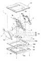
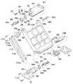
【図3】図1に示すモニタ装置のリンク組立体とベース部材の部分分解斜視図である。
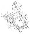
【図4】図3に示すリンク組立体の部分拡大斜視図である。
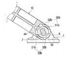
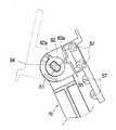
【図5】図4に示すリンク組立体の分解斜視図である。
【図6】本発明の第1の実施の形態にかかるモニタ装置の動作状態を説明するための部分拡大側面図である。
【図7】本発明の第1の実施の形態にかかるモニタ装置の動作状態を説明するための部分拡大側面図である。
【図8】本発明の第1の実施の形態にかかるモニタ装置の動作状態を説明するための部分拡大側面図である。
【図9】本発明の第1の実施の形態にかかるモニタ装置の動作状態を説明するための部分拡大側面図である。
【図10】図6に対応して,本発明の第1の実施の形態にかかるモニタ装置の動作状態によるベースヒンジ領域の部分拡大断面図である。
【図11】図7に対応して,本発明の第1の実施の形態にかかるモニタ装置の動作状態によるベースヒンジ領域の部分拡大断面図である。
【図12】図8及び図9に対応して,本発明の第1の実施の形態にかかるモニタ装置の動作状態によるベースヒンジ領域の部分拡大断面図である。
【図13】図6に対応して,本発明の第1の実施の形態にかかるモニタ装置の動作状態によるモニタヒンジ領域の部分拡大断面図である。
【図14】図7に対応して,本発明の第1の実施の形態にかかるモニタ装置の動作状態によるモニタヒンジ領域の部分拡大断面図である。
【図15】図8に対応して,本発明の第1の実施の形態にかかるモニタ装置の動作状態によるモニタヒンジ領域の部分拡大断面図である。
【図16】図9に対応して,本発明の第1の実施の形態にかかるモニタ装置の動作状態によるモニタヒンジ領域の部分拡大断面図である。
【図17】本発明の第1の実施の形態にかかるモニタ装置のリンク部材にケーブルが配置された概略斜視図である。
【図18】本発明の第1の実施の形態にかかるモニタ装置を壁に付着する側面図である。
【図19】本発明の第1の実施の形態にかかるモニタ装置を壁に付着する側面図である。
【図20】本発明の第1の実施の形態にかかるモニタ装置のアームスタンドに付着する側面図である。
【図21】本発明の第1の実施の形態にかかるモニタ装置のアームスタンドに付着する側面図である。
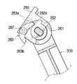
【図22】本発明の第2の実施の形態にかかるモニタ装置の斜視図である。
【図23】本発明の第2の実施の形態にかかるモニタ装置の部分拡大斜視図である。
【図24】本発明の第2の実施の形態にかかるモニタ装置の部分分解斜視図である。
【図25】本発明の第2の実施の形態にかかるモニタ装置の動作状態による部分拡大側面図である。
【図26】本発明の第2の実施の形態にかかるモニタ装置の動作状態による部分拡大側面図である。
【図27】本発明の第2の実施の形態にかかるモニタ装置の動作状態による部分拡大側面図である。
【図28】本発明の第2の実施の形態にかかるモニタ装置の動作状態による部分拡大側面図である。
【図29】本発明の第2の実施の形態にかかるモニタ装置で,図25に対応するベースヒンジ領域の部分拡大断面図である。
【図30】本発明の第2の実施の形態にかかるモニタ装置で,図26に対応するベースヒンジ領域の部分拡大断面図である。
【図31】本発明の第2の実施の形態にかかるモニタ装置で,図27及び図28に対応するベースヒンジ領域の部分拡大断面図である。
【図32】本発明の第2の実施の形態にかかるモニタ装置で,図25に対応するモニタヒンジ領域の部分拡大断面図である。
【図33】本発明の第2の実施の形態にかかるモニタ装置で,図26に対応するモニタヒンジ領域の部分拡大断面図である。
【図34】本発明の第2の実施の形態にかかるモニタ装置で,図26に対応するモニタヒンジ領域の部分拡大断面図である。
【図35】本発明の第2の実施の形態にかかるモニタ装置で,図28に対応するモニタヒンジ領域の部分拡大断面図である。
【図36】従来のモニタ装置の背面斜視図である。
【符号の説明】
1 リンク組立体
10 リンク部材
20 ベースヒンジ
30 第1ベースヒンジ部
40 第2ベースヒンジ部
50 回動角制限手段
55 支持体
60 モニタ角度制限手段
70 モニタヒンジ
80 第1モニタヒンジ部
90 第2モニタヒンジ部
100,110 補助リンク部材
120 モニタ本体
130 ベース部材
140 ベースブラケット
150 ケーブル組立体
160 壁
170 アームスタンド[0001]
BACKGROUND OF THE INVENTION
The present invention relates to a monitor device, and more particularly to a monitor device having an improved tilting structure of a monitor with respect to a base member and a coupling structure for providing the base member on an inclined surface or the like.
[0002]
[Prior art]
As shown in FIG. 36, the conventional monitor device includes a
[0003]
The lower end of the connecting
[0004]
As a result, as indicated by the arrow (A), the connecting
[0005]
On the other hand, contrary to FIG. 36, a monitor device (not shown) has been developed in which the upper end of the connecting member is rotatably connected to the monitor body, and the lower end of the connecting member is integrally fixed to the base member. Yes. As a result, the user can adjust the gaze angle of the monitor to a different angle.
[0006]
Recently, the demand for monitoring devices has increased rapidly due to the rapid supply of computers. In accordance with this trend, an arm stand that supports the monitor device separately from the monitor device has been produced to satisfy the needs of various consumers. In addition, a connection structure for connecting the individually produced monitor device and the arm stand is defined by the VESA (Video Electronic Standard Association) standard.
[0007]
Prior art document information related to the present invention includes the following.
[0008]
[Patent Document 1]
Korean Utility Model No. 2000-722
[Patent Document 2]
Korean Utility Model No. 2000-827
[Patent Document 3]
Korean Utility Model No. 20-178710
[Patent Document 4]
Korean Utility Model No. 20-191805
[Patent Document 5]
Korean Utility Model No. 20-227925
[Patent Document 6]
Korean Utility Model No. 20-239991
[Patent Document 7]
Korean Utility Model No. 20-251611
[Patent Document 8]
Korean Utility Model No. 20-253576
[Patent Document 9]
Japanese Patent Laid-Open No. 10-214034
[Patent Document 10]
JP-A-11-95866
[Patent Document 11]
JP-A-11-184393
[Patent Document 12]
JP 2000-56695 A
[Patent Document 13]
JP 2000-242363 A
[Patent Document 14]
US Pat. No. 5,812,368
[Patent Document 15]
US Pat. No. 5,835,342
[Patent Document 16]
US Pat. No. 6,018,847
[Patent Document 17]
US Pat. No. 6,031,714
[0009]
[Problems to be solved by the invention]
However, in such a conventional monitor device, since the base member can be arranged only on a horizontal plane, it cannot be provided on an inclined surface such as a wall surface or a separate monitor arm stand. There is. Further, since the monitor main body is not folded over the base member plate surface, only the packaging in the state shown in FIG. 36 or the state where only the connecting member is folded over the base member plate surface (not shown) can be obtained. Absent. Therefore, there is a problem that the packaging bulk cannot be reduced and the cost for storage and transportation must be increased. Furthermore, when there are different regulations that limit the rotation angle of the monitor body relative to the base member, there is a problem in that the connection member provided in the conventional monitor device cannot properly compensate for this problem. .
[0010]
In order to solve the above-described problems, the object of the present invention is to appropriately adjust the rotation angle of the monitor body with respect to the base member, to reduce the packaging volume, and to reduce the cost for storage and transportation. It is to provide a monitor device that can be used.
[0011]
Another object of the present invention is to provide a monitor device in which the base member can be provided on an inclined surface such as a wall surface or an arm stand, and in particular, can be easily provided on various arm stands according to the VESA standard. .
[0012]
[Means for Solving the Problems]
In order to solve the above problems, according to a main aspect of the present invention, there is provided a monitor device including a monitor main body and a base member that supports the monitor main body, and is interposed between the monitor main body and the base member. A link member that is capable of rotating with respect to the plate surface of the base member within a predetermined angle range.Like A base hinge rotatably connecting the one end of the link member and the base member; and connecting the other end of the link member and the monitor main body at a position spaced apart from the base hinge so as to be able to tilt each other.A support hinge coupled to the monitor body and pivotally coupled to the other end of the link member; and a link support portion pivotally coupled to the other end of the link member; A hinge pin that has one end rotatably coupled to the support so as to have a predetermined frictional force, and the other end coupled non-rotatably to the link support; A monitor hinge having a rotation of the link member relative to the base member;Rotation of the monitor body relative to the link member with the hinge pin as a rotation center One end connected to the base hinge and the other end to the monitor hingeThe link support part of To rotate the link member relative to the base member., Rotation of the hinge pin through the link support of the monitor hinge A bar-shaped auxiliary link member that transmits toWhen an external force greater than the predetermined frictional force between the hinge pin of the monitor hinge and the support is applied to the monitor body, the monitor body is rotated about the hinge pin of the monitor hinge. The monitor body, the link member and the base plate can be folded until the monitor body is substantially parallel to the plate surface of the base plate. A monitoring device is provided.
[0013]
Here, it is preferable to further include a base bracket coupled to the base member so that the base member can be provided on an inclined surface. Preferably, the base bracket includes a locking projection that is detachable from the base member and is coupled to at least one locking projection receiving hole formed in the base member.
[0014]
The base bracket preferably includes at least one first fastening hole for attaching the base bracket to the inclined surface.
[0015]
The base bracket and the link member include at least one second fastening hole provided in the base bracket for mutual fastening, and a third fastening hole provided in the link member corresponding to the second fastening hole. Is preferred.
[0016]
The second fastening hole of the base bracket and the third fastening hole of the link member are preferably formed according to VESA standards.
[0017]
A first pair disposed at a predetermined separation interval and fixed to the base member.Fixed Bracket and secondFixed The base hinge further includes a first base hinge portion and a second base hinge portion that pivotally connect both one free ends of the link member to the first fixed bracket and the second fixed bracket, respectively. It is preferable to contain.
[0018]
The first base hinge part includes a first pin receiving part formed on a side surface of the link member; a non-circular first boss receiving part formed on the first fixing bracket; and one end of the first pin receiving part. Preferably, the receiving portion includes a first hinge pin rotatably inserted into the receiving portion and aligned with the first boss receiving portion.
[0019]
The first fixed bracket has a spring support portion formed at its inner end so as to protrude toward the second fixed bracket, and the link member is formed on the plate surface of the base member. It is preferable that a torsion coil spring that is elastically biased in the direction of downward rotation is provided.
[0020]
The second base hinge portion includes a second pin receiving portion formed on a side surface of the link member; a first link support portion provided on the second fixing bracket and having a second boss receiving portion formed on the inside thereof; One end is rotatably inserted into the second pin receiving portion, and the other end preferably includes a second hinge pin aligned with the second boss receiving portion of the one link support portion.
[0021]
It is preferable that at least one of the first base hinge part and the second base hinge part is provided with a rotation angle limiting unit that limits a rotation angle of the link member with respect to the base member.
[0022]
The rotation angle limiting means is radially arranged so as to face each other at a distance from at least one of both surfaces of the link member on which the first pin receiving portion and the second pin receiving portion are formed. The first stopper and the second stopper that are cut off; and at least one of the first boss receiving portion and the second boss receiving portion facing each other according to the rotation direction of the link member. And a pair of protrusions that are selectively locked and maintained on the first stopper and the second stopper.
[0023]
The rotation angle limiting means includes a pair of first stoppers radially cut so as to be opposed to each other with a separation interval on a side surface of the link member on which the second pin receiving portion is formed, and the second hinge pin And a first rotation restricting washer formed with a pair of protrusions that are selectively locked to the first stoppers according to the rotation direction of the link member.
[0024]
The monitor hinge is It is preferable to include a first monitor hinge part and a second monitor hinge part that rotatably connect both of the other ends of the link member to both of the supports.
[0025]
The first monitor hinge part includes a first hinge receiving part formed in a depression on one surface of the support; a first hinge insertion part formed on one upper part of the link member; and the first hinge insertion part And a receiving portion cover disposed in an open region of the first hinge receiving portion after being inserted into the first hinge receiving portion.
[0026]
The second monitor hinge portion includes a third pin receiving portion formed on the other surface of the support; a second hinge receiving portion formed on the other side of the link member; and the second monitor receiving portion outside the link member. A second hinge insertion portion rotatably inserted into the hinge receiving portion; the second hinge insertion portion; a second link support portion having a third boss receiving portion formed inside the second hinge insertion portion; ;The hinge pin has one end The other end of the support is rotatably inserted into the third pin receiving portion.But A third hinge pin aligned with the third boss receiving portion of the second link support portionIs It is preferable.
[0027]
Preferably, the second monitor hinge portion is provided with monitor angle limiting means for limiting a rotation angle of the monitor main body with respect to the link member.
[0028]
The monitor angle limiting means includes: a third stopper having a partial arc shape protruding from an opening surface of the third pin receiving portion on an end surface of the support on which the third pin receiving portion is formed; And a rotation limiting washer formed with protrusions for selectively locking and maintaining at both ends of the third stopper according to the rotation direction of the monitor body; and the third pin receiving portion formed And a leaf spring that is coupled to an end surface of the support and pressurizes the protrusion of the rotation restricting washer to suppress the rotation of the support.
[0029]
It is preferable that the plate spring has a protrusion that can be elastically deformed on a plate surface, and one end of the plate spring is fastened to one end of the support. The first monitor hinge portion includes a third pin receiving portion formed on one surface of the support; a fourth pin receiving portion formed on one upper end of the link member; and the third and fourth pin receiving portions. And a third hinge pin having both end portions respectively inserted into the portion.
[0030]
The second monitor hinge part includes a fifth pin receiving part formed on the other surface of the support; a sixth pin receiving part formed on the other upper end of the link member; A second link support portion rotatably inserted into the sixth pin receiving portion and having a spline receiving portion formed therein;The hinge pin has one end The other end is press-fitted into the fifth pin receiving portion of the support.But A fourth hinge pin aligned with the spline receiving portion of the second link support portion;Is It is preferable.
[0031]
Preferably, the second monitor hinge portion is provided with monitor angle limiting means for limiting a rotation angle of the monitor main body with respect to the link member. The monitor angle limiting means is coupled to the fourth hinge pin; a partial arc-shaped second stopper projecting from around the fifth pin receiving portion on one surface of the support on which the fifth pin receiving portion is formed; A second rotation restricting washer formed with protrusions for selectively locking and maintaining both ends of the second stopper according to the rotation direction of the monitor main body; and the fifth pin receiving portion formed And a third stopper that is coupled to one surface of the support and is engaged with and released from the protruding portion of the second rotation restricting washer.
[0032]
A second torsion coil spring that is coupled to one surface of the support body on which the fifth pin receiving portion is formed and elastically biased in a direction in which the third stopper engages with the protruding portion of the second rotation restricting washer. It is preferable that it is further included. It is preferable that a spacer interposed between the second link support portion and the second rotation limit washer is further included.
[0033]
It is preferable that the auxiliary link member is provided as a pair that is coupled to the first link support portion and the second link support portion in an integrated manner.
[0034]
The first link support part and the second link support part are formed with a plurality of pin insertion holes formed at a predetermined separation interval, and the pin insertion holes are formed at both ends of each auxiliary link member. It is preferable that a communicating through hole is formed, and a link coupling pin is integrally inserted into the through hole and the pin insertion hole.
[0035]
A cable for connecting at least one first cable port provided in one area of the base member and at least one second cable port connected to one area of the monitor body on the plate surface of the link member. Preferably, a cable receiving portion for receiving the cable is provided, and the first hinge insertion portion and the first hinge receiving portion of the support body have a cable receiving groove for receiving the cable.
[0036]
The monitor body can be folded and overlapped in parallel with the plate surface of the base member, and the link member can be received in a link member receiving hole formed so as to penetrate the center of the plate surface of the base member. It is preferable to make it.
[0037]
When the link member is rotated, the monitor main body is at an angle like the second link support portion while the second link support portion provided at the upper end of the link member is rotated by the auxiliary link member. It is preferable to rotate. The auxiliary link member may be the base hinge.When Monitor hingeBetween It is preferable to arrange in parallel with the link member.
[0038]
DETAILED DESCRIPTION OF THE INVENTION
Hereinafter, embodiments of the present invention will be described in detail with reference to the accompanying drawings. Hereinafter, embodiments of the present invention will be described with reference to the drawings. In the present specification and drawings, components having substantially the same functional configuration are denoted by the same reference numerals, and redundant description is omitted.
[0039]
As shown in FIGS. 1 and 2, the monitor device according to the first embodiment of the present invention includes a
[0040]
The
[0041]
As shown in FIGS. 3 to 5, the
[0042]
The
[0043]
The
[0044]
The
[0045]
The
[0046]
The first
[0047]
The
[0048]
The second
[0049]
The first
[0050]
The rotation angle limiting means 50a and 50b (see FIGS. 5 and 10) are spaced apart from each other at a predetermined distance from the
[0051]
Accordingly, when the
[0052]
Conversely, when the
[0053]
Thus, the link member for the
[0054]
At the
[0055]
The
[0056]
The first monitor hinge portion 80 (see FIGS. 4 and 5) includes a first
[0057]
The second monitor hinge portion 90 (see FIGS. 4 and 5) includes a third pin receiving portion 91 formed on the left side surface of the
[0058]
One end 94a of the
[0059]
The
[0060]
The monitor angle limiting means 60 (see FIG. 5) includes a partial arc-shaped
[0061]
A noncircular through
[0062]
The
[0063]
Accordingly, when the
[0064]
If the
[0065]
The process of returning the moved monitor
[0066]
On the other hand, the
[0067]
For this reason, in this embodiment,
[0068]
The
[0069]
The operation process of each part of the monitor device according to the first embodiment of the present invention will be described as follows. As shown in FIGS. 6 to 9, with the monitor device arranged as shown in FIG. 6 (see FIGS. 10 and 13), the
[0070]
When the
[0071]
In the state of FIG. 7, the
[0072]
In the state shown in FIG. 8, when the monitor
[0073]
In order to use the monitor device in the state of FIG. 9 (see FIGS. 12 and 16), the change to the state of FIG. 6 is performed through the reverse process described above, and the description thereof will be omitted.
[0074]
Thus, if the monitor device is packaged in a state in which the monitor
[0075]
FIG. 17 is a schematic view in which a cable is arranged on the link member of the monitor device according to the first embodiment of the present invention. A
[0076]
18 and 19 are side views of attaching the monitor device according to the first embodiment of the present invention to a wall. First, the
[0077]
20 and 21 are side views of attaching the monitor device according to the first embodiment of the present invention to the arm stand. As shown in this drawing, first, the locking
[0078]
In the above-described embodiment, the torsion coil spring for slowly rotating the link member is provided in the first base hinge portion. However, the torsion coil spring can be provided in the second base hinge portion.
[0079]
Similarly, monitor angle limiting means for limiting the rotation angle of the monitor can be provided in the first monitor hinge portion.
[0080]
As shown in FIGS. 22 to 24, the monitor device according to the second embodiment of the present invention includes a
[0081]
The
[0082]
The first
[0083]
One
[0084]
The
[0085]
Since the first
[0086]
The second
[0087]
One
[0088]
The second
[0089]
The rotation angle limiting means 250 (FIGS. 24 and 29 to 31) is opposed to the left side surface of the
[0090]
A non-circular through
[0091]
As a result, when the
[0092]
On the other hand, when the
[0093]
As described above, the rotation angle range of the
[0094]
At the
[0095]
The
[0096]
The first
[0097]
The second
[0098]
The
[0099]
The
[0100]
The monitor angle limiting means 260 is coupled to the
[0101]
A non-circular through
[0102]
The
[0103]
A second torsion
[0104]
A
[0105]
As a result, when the monitor
[0106]
When the monitor
[0107]
At this time, a means for returning the moved
[0108]
On the other hand, with the above configuration, the
[0109]
Therefore, also in the second embodiment of the present invention,
[0110]
As in the first embodiment, the
[0111]
Accordingly, the through
[0112]
The operation process of each part of the monitor device having such a configuration will be described as follows.
[0113]
The
[0114]
When the
[0115]
In the state of FIG. 26, the
[0116]
In the state as shown in FIG. 27, when the monitor
[0117]
In this state, when the upper end of the
[0118]
In the state of FIG. 28 (included in FIG. 31 and FIG. 35), in order to use the monitor device, the change to the state of FIG.
[0119]
Thus, if the monitor device is packaged in a state where the monitor
[0120]
The preferred embodiment according to the present invention has been described above, but the present invention is not limited to such a configuration. A person skilled in the art can assume various modifications and changes within the scope of the technical idea described in the claims, and the modifications and changes are also within the technical scope of the present invention. It is understood that it is included in
[0121]
【The invention's effect】
As described above, according to the present invention, the tilting of the monitor body with respect to the base member can be adjusted appropriately, the packaging volume can be reduced, and the cost for storage and transportation can be reduced. A monitoring device can be provided.
[0122]
Further, since the base bracket is provided, the base member can be provided on an inclined surface such as a wall surface or an arm stand, and in particular, a monitor device that can be easily provided on various arm stands according to the VESA standard can be provided. .
[Brief description of the drawings]
FIG. 1 is a rear perspective view of a monitor device according to a first embodiment of the present invention.
FIG. 2 is a rear perspective view of the monitor device in which the base member and the base bracket according to the first embodiment of the present invention are separated.
3 is a partially exploded perspective view of a link assembly and a base member of the monitor device shown in FIG.
4 is a partially enlarged perspective view of the link assembly shown in FIG. 3. FIG.
5 is an exploded perspective view of the link assembly shown in FIG. 4. FIG.
FIG. 6 is a partially enlarged side view for explaining an operating state of the monitor device according to the first embodiment of the present invention.
FIG. 7 is a partially enlarged side view for explaining an operating state of the monitor device according to the first embodiment of the present invention.
FIG. 8 is a partially enlarged side view for explaining an operation state of the monitor device according to the first embodiment of the present invention.
FIG. 9 is a partially enlarged side view for explaining an operating state of the monitor device according to the first embodiment of the present invention.
FIG. 10 is a partially enlarged cross-sectional view of a base hinge region according to the operating state of the monitor device according to the first embodiment of the present invention, corresponding to FIG. 6;
FIG. 11 is a partial enlarged cross-sectional view of a base hinge region according to the operating state of the monitor device according to the first embodiment of the present invention, corresponding to FIG. 7;
FIG. 12 is a partially enlarged cross-sectional view of the base hinge region according to the operating state of the monitor device according to the first embodiment of the present invention, corresponding to FIGS. 8 and 9;
FIG. 13 is a partially enlarged cross-sectional view of a monitor hinge region according to the operating state of the monitor device according to the first embodiment of the present invention, corresponding to FIG. 6;
FIG. 14 is a partially enlarged cross-sectional view of a monitor hinge region according to the operating state of the monitor device according to the first embodiment of the present invention, corresponding to FIG. 7;
FIG. 15 is a partially enlarged cross-sectional view of a monitor hinge region according to the operating state of the monitor device according to the first embodiment of the present invention, corresponding to FIG. 8;
FIG. 16 is a partially enlarged cross-sectional view of a monitor hinge region according to the operating state of the monitor device according to the first embodiment of the present invention, corresponding to FIG. 9;
FIG. 17 is a schematic perspective view in which a cable is arranged on a link member of the monitor device according to the first embodiment of the present invention.
FIG. 18 is a side view of attaching the monitor device according to the first embodiment of the present invention to a wall.
FIG. 19 is a side view of attaching the monitor device according to the first embodiment of the present invention to a wall.
FIG. 20 is a side view attached to the arm stand of the monitor device according to the first embodiment of the present invention.
FIG. 21 is a side view attached to the arm stand of the monitor device according to the first embodiment of the present invention.
FIG. 22 is a perspective view of a monitor device according to a second embodiment of the present invention.
FIG. 23 is a partially enlarged perspective view of a monitor device according to a second embodiment of the present invention.
FIG. 24 is a partially exploded perspective view of a monitor device according to a second embodiment of the present invention.
FIG. 25 is a partially enlarged side view according to an operating state of the monitor device according to the second embodiment of the present invention.
FIG. 26 is a partially enlarged side view according to the operating state of the monitor device according to the second embodiment of the present invention.
FIG. 27 is a partially enlarged side view of the monitor device according to the second embodiment of the present invention according to the operating state.
FIG. 28 is a partially enlarged side view according to an operating state of the monitor device according to the second embodiment of the present invention.
FIG. 29 is a partial enlarged cross-sectional view of a base hinge region corresponding to FIG. 25 in the monitor device according to the second embodiment of the present invention.
FIG. 30 is a partially enlarged cross-sectional view of a base hinge region corresponding to FIG. 26 in the monitor device according to the second embodiment of the present invention.
FIG. 31 is a partially enlarged cross-sectional view of a base hinge region corresponding to FIGS. 27 and 28 in the monitor device according to the second embodiment of the present invention.
FIG. 32 is a partially enlarged cross-sectional view of a monitor hinge region corresponding to FIG. 25 in the monitor device according to the second embodiment of the present invention.
FIG. 33 is a partial enlarged cross-sectional view of a monitor hinge region corresponding to FIG. 26 in the monitor device according to the second embodiment of the present invention.
FIG. 34 is a partial enlarged cross-sectional view of a monitor hinge region corresponding to FIG. 26 in the monitor device according to the second embodiment of the present invention.
FIG. 35 is a partial enlarged cross-sectional view of a monitor hinge region corresponding to FIG. 28 in the monitor device according to the second embodiment of the present invention.
FIG. 36 is a rear perspective view of a conventional monitor device.
[Explanation of symbols]
1 Link assembly
10 Link members
20 Base hinge
30 1st base hinge part
40 Second base hinge
50 Rotation angle limiting means
55 Support
60 Monitor angle limiting means
70 Monitor hinge
80 1st monitor hinge part
90 Second monitor hinge
100, 110 Auxiliary link member
120 Monitor body
130 Base member
140 Base bracket
150 Cable assembly
160 walls
170 Arm stand
Claims (31)
Translated fromJapanese前記モニタ本体と前記ベース部材との間に介在するリンク部材と;
所定の角度範囲内で前記リンク部材が前記ベース部材の板面に対して回動可能なように,前記リンク部材の一端と前記ベース部材とを回動可能に連結するベースヒンジと;
前記ベースヒンジと離隔した位置で前記リンク部材の他端と前記モニタ本体を相互ティルティング可能に連結するモニタヒンジであって,前記モニタ本体に結合されるとともに前記リンク部材の他端に回動可能に結合される支持体と,前記リンク部材の他端に回動可能に結合されるリンク支持部と,一端が前記支持体に所定の摩擦力を有するように回動可能に結合され,他端が前記リンク支持部に回動不能に結合されるヒンジピンと,を有するモニタヒンジと;
前記ベース部材に対する前記リンク部材の回動を,前記ヒンジピンを回動中心とする前記リンク部材に対する前記モニタ本体の回動に伝達するように,一端が前記ベースヒンジに連結され他端が前記モニタヒンジの前記リンク支持部に対して連結されて,前記ベース部材に対する前記リンク部材の回動を,前記モニタヒンジの前記リンク支持部を介して前記ヒンジピンの回転に伝達するバー形状の補助リンク部材と;
を含み,
前記モニタヒンジの前記ヒンジピンと前記支持体との間の前記所定の摩擦力より大きい外力が前記モニタ本体に加えられたときに,前記モニタ本体を前記モニタヒンジの前記ヒンジピンを中心として回動させて,前記モニタ本体が前記ベース板の板面に対して略平行となるまで前記モニタ本体,前記リンク部材及び前記ベース板を折り重ねることが可能であることを特徴とするモニタ装置。A monitor device including a monitor body and a base member that supports the monitor body,
A link member interposed between the monitor body and the base member;
A base hinge that rotatably connects one end of the link member and the base membersuch that the link member can rotate with respect to the plate surface of the base member within a predetermined angle range;
Amonitor hinge for connecting the other end of the link member and the monitor main body at a position separated from the base hinge so as to be tiltable with each other, andis coupled to the monitor main body and is rotatable to the other end of the link member A support body coupled to the other end of the link member, and a link support section pivotably coupled to the other end of the link member, and one end pivotably coupled to the support body so as to have a predetermined frictional force. A hinge pin that is non-rotatably coupled to the link support ;
One end is connected to the base hinge and the other end is the monitor hingeso as to transmitthe rotation of thelink member with respect to the base member to the rotation ofthe monitor body with respect to the link member with the hinge pin as a rotation center.A bar-shaped auxiliary link member that is connected to thelink support part and transmits the rotation ofthe link member relative to the base member to the rotation ofthe hinge pin via the link support part of the monitor hinge ;
Including
When an external force greater than the predetermined frictional force between the hinge pin of the monitor hinge and the support is applied to the monitor body, the monitor body is rotated about the hinge pin of the monitor hinge. The monitor main body, the link member, and the base plate can be folded until the monitor main body is substantially parallel to the plate surface of the base plate .
前記ベースヒンジは,前記リンク部材の一方自由端部の両方を前記第1固定ブラケット及び第2固定ブラケットにそれぞれ回動可能に連結する第1ベースヒンジ部及び第2ベースヒンジ部を含むことを特徴とする請求項1に記載のモニタ装置。A firstfixing bracket and a secondfixing bracket which are arranged in a pair at a predetermined separation interval and are fixed to the base member;
The base hinge includes a first base hinge portion and a second base hinge portion that pivotally connect both of the free ends of the link member to the first fixed bracket and the second fixed bracket, respectively. The monitor device according to claim 1.
前記リンク部材の側面に形成された第1ピン受容部と;
前記第1固定ブラケットに形成された非円形状の第1ボス受容部と;
一端は前記第1ピン受容部に回動可能に挿入され,他端は前記第1ボス受容部に整合する第1ヒンジピンと;
を含むことを特徴とする請求項7に記載のモニタ装置。The first base hinge part is
A first pin receiving portion formed on a side surface of the link member;
A non-circular first boss receiving portion formed on the first fixing bracket;
One end pivotally inserted into the first pin receiving portion and the other end is a first hinge pin aligned with the first boss receiving portion;
The monitor device according to claim 7, comprising:
前記スプリング支持部には,前記リンク部材が前記ベース部材の板面に下向き回動する方向に反対に弾性付勢する捻りコイルスプリングが設けられていることをと特徴とする請求項7または8に記載のモニタ装置。The first fixed bracket has a spring support portion formed to protrude toward the second fixed bracket at an inner end portion thereof,
9. The torsion coil spring that elastically urges the link member in a direction opposite to the direction in which the link member pivots downward on the plate surface of the base member is provided on the spring support portion. The monitoring device described.
前記リンク部材の側面に形成された第2ピン受容部と;
前記第2固定ブラケットに設けられ,内側に第2ボス受容部が形成された第1リンク支持部と;
一端は第2ピン受容部に回動可能に挿入され,他端は前記1リンク支持部の第2ボス受容部に整合する第2ヒンジピンと;
を含むことを特徴とする請求項7に記載のモニタ装置。The second base hinge part is
A second pin receiving portion formed on a side surface of the link member;
A first link support portion provided on the second fixing bracket and having a second boss receiving portion formed inside;
One end is rotatably inserted into the second pin receiving portion, and the other end is a second hinge pin aligned with the second boss receiving portion of the one link support portion;
The monitor device according to claim 7, comprising:
前記第1ピン受容部及び第2ピン受容部が形成された前記リンク部材の両方面のうち少なくともいずれか一つに離隔間隔をおいて相互対向するように放射状に切取られた第1ストッパー及び第2ストッパーと;
前記第1ボス受容部及び第2ボス受容部の相互対向側の端部のうち少なくともいずれか一つに前記リンク部材の回動方向にしたがって前記第1ストッパー及び第2ストッパーに選択的に係止維持する一対の突出部と;
を含むことを特徴とする請求項11に記載のモニタ装置。The rotation angle limiting means is:
A first stopper and a first stopper that are radially cut so as to face each other at a distance from at least one of both surfaces of the link member on which the first pin receiving portion and the second pin receiving portion are formed. 2 stoppers;
The first boss receiving portion and the second boss receiving portion are selectively locked to the first stopper and the second stopper according to the rotation direction of the link member at least one of the opposite ends of the second boss receiving portion. A pair of protrusions to maintain;
The monitor device according to claim 11, comprising:
前記第2ピン受容部が形成された前記リンク部材の側面に離隔間隔をおいて相互対向するように放射状に切取られた一対の第1ストッパーと,
前記第2ヒンジピンに結合され,前記リンク部材の回動方向にしたがって前記各第1ストッパーに選択的に係止維持する一対の突出部が形成された第1回動制限ワッシャーと,
を含むことを特徴とする請求項11に記載のモニタ装置。The rotation angle limiting means is:
A pair of first stoppers radially cut so as to be opposed to each other at a distance from a side surface of the link member on which the second pin receiving portion is formed;
A first rotation restricting washer coupled to the second hinge pin and formed with a pair of protrusions for selectively locking and maintaining the first stopper according to the rotation direction of the link member;
The monitor device according to claim 11, comprising:
前記支持体の一方面に陥没形成された第1ヒンジ受容部と;
前記リンク部材の上部一方に形成された第1ヒンジ挿入部と;
前記第1ヒンジ挿入部が前記第1ヒンジ受容部に挿入された後,前記第1ヒンジ受容部の開放された一領域に配置される受容部カバーと;
を含むことを特徴とする請求項14に記載のモニタ装置。The first monitor hinge part is
A first hinge receiving part formed in a depression on one side of the support;
A first hinge insertion portion formed on one upper side of the link member;
A receiving portion cover disposed in an open region of the first hinge receiving portion after the first hinge inserting portion is inserted into the first hinge receiving portion;
The monitor device according to claim 14, comprising:
前記支持体の他方面に形成された第3ピン受容部と;
前記リンク部材の他方に形成された第2ヒンジ受容部と;
前記リンク部材の外側に前記第2ヒンジ受容部に回転可能に挿入される第2ヒンジ挿入部と;
前記第2ヒンジ挿入部と,前記第2ヒンジ挿入部の内側に形成された第3ボス受容部を有する第2リンク支持部と;
を含み,
前記ヒンジピンは,一端が前記支持体の第3ピン受容部に回動可能に挿入され,他端が前記第2リンク支持部の第3ボス受容部に整合する第3ヒンジピンであることを特徴とする請求項14または15に記載のモニタ装置。The second monitor hinge is
A third pin receiving portion formed on the other surface of the support;
A second hinge receiving portion formed on the other of the link members;
A second hinge insertion part rotatably inserted into the second hinge receiving part on the outside of the link member;
A second link support portion having a second boss receiving portion formed inside the second hinge insertion portion and the second hinge insertion portion;
Including
The hinge pin is a third hinge pin that has one end rotatably inserted into a third pin receiving portion of the support and the other end aligned with a third boss receiving portion of the second link support portion. The monitor device according to claim 14 or 15.
前記第3ピン受容部が形成された前記支持体の端部面に前記第3ピン受容部の開口面から突出した部分円弧形状の第3ストッパーと;
前記第3ヒンジピンに結合され,前記モニタ本体の回動方向にしたがって前記第3ストッパーの両端に選択的に係止維持する突出部が形成された回動制限ワッシャーと;
前記第3ピン受容部が形成された前記支持体の端部面に結合して前記回動制限ワッシャーの前記突出部を加圧して前記支持体の回動を抑制させる板スプリングと;
を含むことを特徴とする請求項17に記載のモニタ装置。The monitor angle limiting means includes
A partial arc-shaped third stopper projecting from an opening surface of the third pin receiving portion on an end surface of the support on which the third pin receiving portion is formed;
A rotation limiting washer coupled to the third hinge pin and formed with protrusions for selectively locking and maintaining at both ends of the third stopper according to the rotation direction of the monitor body;
A leaf spring coupled to an end surface of the support on which the third pin receiving portion is formed and pressurizing the protrusion of the rotation limiting washer to suppress the rotation of the support;
The monitor device according to claim 17, comprising:
前記支持体の一方面に形成された第3ピン受容部と;
前記リンク部材の上端一方に形成された第4ピン受容部と;
前記第3及び第4ピン受容部にそれぞれ挿入される両端部を有する第3ヒンジピンと;
を含むことを特徴とする請求項14に記載のモニタ装置。The first monitor hinge part is
A third pin receiving portion formed on one side of the support;
A fourth pin receiving portion formed on one upper end of the link member;
A third hinge pin having both ends inserted into the third and fourth pin receiving parts, respectively;
The monitor device according to claim 14, comprising:
前記支持体の他方面に形成された第5ピン受容部と;
前記リンク部材の上端の他方に形成された第6ピン受容部と;
前記リンク部材の外側で前記第6ピン受容部に回転可能に挿入され,内側にスプライン受容部が形成された第2リンク支持部と;
を含み,
前記ヒンジピンは,一端が前記支持体の第5ピン受容部に圧入され,他端が前記第2リンク支持部のスプライン受容部に整合する第4ヒンジピンであることを特徴とする請求項14または20に記載のモニタ装置。The second monitor hinge is
A fifth pin receiving portion formed on the other surface of the support;
A sixth pin receiving portion formed on the other upper end of the link member;
A second link support portion rotatably inserted into the sixth pin receiving portion outside the link member and having a spline receiving portion formed inside;
Including
21. The hinge pin according to claim 14, wherein one end of the hinge pin is press-fitted into a fifth pin receiving portion of the support and the other end is a fourth hinge pin aligned with the spline receiving portion of the second link support portion. The monitoring device described in 1.
前記第5ピン受容部が形成された前記支持体の一方面に前記第5ピン受容部の周りから突出した部分円弧形状の第2ストッパーと;
前記第4ヒンジピンに結合され,前記モニタ本体の回動方向にしたがって前記第2ストッパーの両端に選択的に係止維持する突出部が形成された第2回動制限ワッシャーと;
前記第5ピン受容部が形成された前記支持体の一方面に結合して前記第2回動制限ワッシャーの突出部に係止及び係止解除する第3ストッパーと;
を含むことを特徴とする請求項22に記載のモニタ装置。The monitor angle limiting means includes
A partially arcuate second stopper projecting from around the fifth pin receiving portion on one surface of the support on which the fifth pin receiving portion is formed;
A second rotation restricting washer coupled to the fourth hinge pin and formed with protrusions for selectively locking and maintaining both ends of the second stopper according to the rotation direction of the monitor body;
A third stopper that is coupled to one surface of the support body on which the fifth pin receiving portion is formed and is engaged with and released from the protruding portion of the second rotation restricting washer;
The monitor device according to claim 22, comprising:
Applications Claiming Priority (6)
| Application Number | Priority Date | Filing Date | Title |
|---|---|---|---|
| KR2001-071860 | 2001-11-19 | ||
| KR20010071860 | 2001-11-19 | ||
| KR10-2002-0027683AKR100520059B1 (en) | 2002-05-20 | 2002-05-20 | Monitor |
| KR2002-027683 | 2002-05-20 | ||
| KR10-2002-0056429AKR100512719B1 (en) | 2001-11-19 | 2002-09-17 | Monitor |
| KR2002-056429 | 2002-09-17 |
Related Child Applications (3)
| Application Number | Title | Priority Date | Filing Date |
|---|---|---|---|
| JP2005360915ADivisionJP4169756B2 (en) | 2001-11-19 | 2005-12-14 | Monitor device |
| JP2005360911ADivisionJP2006154841A (en) | 2001-11-19 | 2005-12-14 | Monitor device |
| JP2005360909ADivisionJP2006154840A (en) | 2001-11-19 | 2005-12-14 | Monitor device |
Publications (2)
| Publication Number | Publication Date |
|---|---|
| JP2003280533A JP2003280533A (en) | 2003-10-02 |
| JP4094937B2true JP4094937B2 (en) | 2008-06-04 |
Family
ID=36633120
Family Applications (4)
| Application Number | Title | Priority Date | Filing Date |
|---|---|---|---|
| JP2002333914AExpired - Fee RelatedJP4094937B2 (en) | 2001-11-19 | 2002-11-18 | Monitor device |
| JP2005360911APendingJP2006154841A (en) | 2001-11-19 | 2005-12-14 | Monitor device |
| JP2005360909APendingJP2006154840A (en) | 2001-11-19 | 2005-12-14 | Monitor device |
| JP2005360915AExpired - Fee RelatedJP4169756B2 (en) | 2001-11-19 | 2005-12-14 | Monitor device |
Family Applications After (3)
| Application Number | Title | Priority Date | Filing Date |
|---|---|---|---|
| JP2005360911APendingJP2006154841A (en) | 2001-11-19 | 2005-12-14 | Monitor device |
| JP2005360909APendingJP2006154840A (en) | 2001-11-19 | 2005-12-14 | Monitor device |
| JP2005360915AExpired - Fee RelatedJP4169756B2 (en) | 2001-11-19 | 2005-12-14 | Monitor device |
Country Status (5)
| Country | Link |
|---|---|
| US (3) | US7604206B2 (en) |
| EP (1) | EP1312851B1 (en) |
| JP (4) | JP4094937B2 (en) |
| CN (1) | CN100395845C (en) |
| DE (1) | DE60218402T2 (en) |
Families Citing this family (134)
| Publication number | Priority date | Publication date | Assignee | Title |
|---|---|---|---|---|
| JP4713744B2 (en)* | 1999-05-10 | 2011-06-29 | イノヴェイティヴ・オフィス・プロダクツ,インコーポレイテッド | Electronic device attachment arm device |
| JP4094937B2 (en) | 2001-11-19 | 2008-06-04 | 三星電子株式会社 | Monitor device |
| US7261267B2 (en)* | 2003-02-03 | 2007-08-28 | Bang & Olufsen A/S | Tilt mechanism |
| KR100826606B1 (en)* | 2003-02-26 | 2008-04-30 | 삼성전자주식회사 | Monitor device |
| KR100770983B1 (en)* | 2003-04-09 | 2007-10-30 | 삼성전자주식회사 | Monitor device |
| KR100770984B1 (en)* | 2003-05-23 | 2007-10-30 | 삼성전자주식회사 | Display device |
| KR100534119B1 (en)* | 2003-08-06 | 2005-12-08 | 삼성전자주식회사 | Monitor |
| FR2860939A1 (en)* | 2003-10-08 | 2005-04-15 | Philippe Marc Dominois | Digital photo frame for digital camera owner, has liquid crystal display screen allowing display of digital photos, and rotating support supporting frame in either horizontal position or vertical position |
| KR100568181B1 (en)* | 2003-10-17 | 2006-04-05 | 삼성전자주식회사 | Display device |
| US6962312B2 (en)* | 2004-01-06 | 2005-11-08 | Amtran Technology Co., Ltd. | Display apparatus with adjustable supporting device |
| KR100526617B1 (en)* | 2004-03-12 | 2005-11-08 | 삼성전자주식회사 | Monitor |
| CN100375131C (en)* | 2004-03-26 | 2008-03-12 | 乐金电子(南京)等离子有限公司 | Fixing device for image display device |
| KR100662367B1 (en)* | 2004-05-06 | 2007-01-02 | 엘지전자 주식회사 | Stand assembly for monitor |
| KR20050107206A (en) | 2004-05-08 | 2005-11-11 | 삼성전자주식회사 | Monitor |
| KR20050109109A (en)* | 2004-05-13 | 2005-11-17 | 삼성전자주식회사 | Monitor |
| EP1619438B1 (en)* | 2004-07-21 | 2010-03-31 | LG Electronics Inc. | Wall mounting structure for a flat panel display |
| KR200364292Y1 (en)* | 2004-07-23 | 2004-10-14 | 주식회사 마메든 | Tilt Controller For Monitor |
| US7770856B2 (en)* | 2004-08-13 | 2010-08-10 | Hewlett-Packard Development Company, L.P. | Thin computer monitor support apparatus |
| KR100628119B1 (en) | 2004-08-17 | 2006-09-26 | 엘지전자 주식회사 | Flat panel monitor |
| US8608119B2 (en)* | 2004-11-23 | 2013-12-17 | Hewlett-Packard Development Company, L.P. | Display stand |
| KR100676324B1 (en)* | 2005-03-15 | 2007-01-30 | 삼성전자주식회사 | Display device |
| JP4638764B2 (en)* | 2005-04-21 | 2011-02-23 | 株式会社ストロベリーコーポレーション | Hinge mechanism and portable terminal |
| US7300029B2 (en)* | 2005-04-28 | 2007-11-27 | Bretford Manufacturing, Inc. | Flat panel display wall mounting system |
| USD523855S1 (en)* | 2005-05-12 | 2006-06-27 | Hon Hai Precision Ind. Co., Ltd. | Liquid crystal display |
| US8794579B2 (en) | 2005-06-03 | 2014-08-05 | Steelcase, Inc. | Support arm assembly |
| KR100880123B1 (en)* | 2005-07-29 | 2009-01-23 | 주식회사 메디슨 | 4-joint monitor support assembly for supporting monitor of ultrasonic diagnostic device |
| KR100697446B1 (en) | 2005-08-04 | 2007-03-20 | 엘지전자 주식회사 | Stand of video display device |
| KR100705063B1 (en)* | 2005-08-10 | 2007-04-06 | 엘지전자 주식회사 | Stand of video display device |
| KR100658836B1 (en)* | 2005-08-16 | 2006-12-15 | 엘지전자 주식회사 | Stand unit |
| KR100816505B1 (en)* | 2005-09-09 | 2008-03-24 | 배석희 | Laptop Table |
| JP3117923U (en)* | 2005-10-24 | 2006-01-19 | 船井電機株式会社 | Liquid crystal television device, liquid crystal display device |
| CN100467891C (en)* | 2005-12-01 | 2009-03-11 | 鸿富锦精密工业(深圳)有限公司 | hinge device |
| KR100846898B1 (en)* | 2005-12-30 | 2008-07-17 | 엘지전자 주식회사 | Stand of video display device |
| TWM292646U (en)* | 2006-01-06 | 2006-06-21 | Shin Zu Shing Co Ltd | Height adjustable pivot connector |
| WO2007086002A1 (en)* | 2006-01-27 | 2007-08-02 | Koninklijke Philips Electronics N.V. | Stand for bearing an apparatus |
| WO2007086025A1 (en)* | 2006-01-27 | 2007-08-02 | Koninklijke Philips Electronics N.V. | Stand and screen holder for use on such a stand |
| EP1826471A3 (en) | 2006-02-28 | 2009-08-05 | Samsung Electronics Co., Ltd. | Monitor apparatus |
| KR101370335B1 (en)* | 2006-02-28 | 2014-03-05 | 삼성전자주식회사 | Monitor apparatus |
| KR101239979B1 (en)* | 2006-03-08 | 2013-03-06 | 삼성전자주식회사 | Display apparatus |
| US7444716B2 (en)* | 2006-04-25 | 2008-11-04 | Shin Zu Shing Co., Ltd | Dual-axle hinge |
| JP2007328069A (en)* | 2006-06-07 | 2007-12-20 | Sharp Corp | Thin type display apparatus and mounting implement therefor |
| KR20080015296A (en)* | 2006-08-14 | 2008-02-19 | 삼성전자주식회사 | Supporting device for display device |
| US20080040887A1 (en)* | 2006-08-16 | 2008-02-21 | Dickerson Harry L | Friction hinge for electronic apparatus |
| TWM307282U (en)* | 2006-09-06 | 2007-03-01 | Jarllytec Co Ltd | Rotating shaft structure with tilt-angle adjustability |
| JP4578452B2 (en)* | 2006-09-15 | 2010-11-10 | シャープ株式会社 | Thin display device |
| JP2008076457A (en)* | 2006-09-19 | 2008-04-03 | Nhk Spring Co Ltd | Display panel support device |
| JP4306726B2 (en) | 2006-12-27 | 2009-08-05 | ソニー株式会社 | Image display device |
| JP5018083B2 (en) | 2006-12-28 | 2012-09-05 | 船井電機株式会社 | Panel-type display device and display device |
| JP2008281602A (en)* | 2007-05-08 | 2008-11-20 | Ebisu Furniture Kk | Display support device |
| CN100592431C (en)* | 2007-06-25 | 2010-02-24 | 孙军 | Display pedestal with cervical vertebra health function |
| US8675354B2 (en)* | 2007-06-27 | 2014-03-18 | Voxx International Corporation | Multi-media memo board |
| TW200907214A (en)* | 2007-08-14 | 2009-02-16 | Jarllytec Co Ltd | Supporting structure having torque transfer function |
| CN101373037B (en)* | 2007-08-21 | 2010-06-16 | 兆利科技工业股份有限公司 | Support structure with torsion transfer function |
| TWM333735U (en)* | 2007-09-07 | 2008-06-01 | Jarllytec Co Ltd | Supporting structure for vertical movement |
| TW200925482A (en)* | 2007-12-06 | 2009-06-16 | Jarllytec Co Ltd | Supporting structure having connecting rod latching function |
| CN101452747B (en)* | 2007-12-07 | 2012-11-21 | 鸿富锦精密工业(深圳)有限公司 | Lifting support frame and four-bar thereof |
| USD636745S1 (en)* | 2007-12-10 | 2011-04-26 | Sony Corporation | Television receiver |
| JP5016469B2 (en)* | 2007-12-18 | 2012-09-05 | 下西技研工業株式会社 | Hinge device |
| JP4893967B2 (en)* | 2008-04-15 | 2012-03-07 | 村田機械株式会社 | Image forming apparatus |
| JP2009258452A (en)* | 2008-04-17 | 2009-11-05 | Murata Mach Ltd | Image forming apparatus |
| KR101458642B1 (en) | 2008-05-27 | 2014-11-05 | 엘지전자 주식회사 | Display apparatus |
| JP2009295249A (en)* | 2008-06-06 | 2009-12-17 | Sharp Corp | Mounting mechanism and display device of drive apparatus |
| US7775494B2 (en)* | 2008-07-11 | 2010-08-17 | Syncmold Enterprise Corp. | Foldable holder |
| KR101470640B1 (en)* | 2008-07-14 | 2014-12-08 | 엘지전자 주식회사 | Display device |
| CN101713486B (en)* | 2008-10-06 | 2012-05-30 | 鸿富锦精密工业(深圳)有限公司 | Electronic device support and electronic device using same |
| CN101770734A (en)* | 2009-01-05 | 2010-07-07 | 鸿富锦精密工业(深圳)有限公司 | Display device and supporting structure thereof |
| JP4799625B2 (en)* | 2009-01-30 | 2011-10-26 | 株式会社東芝 | Display device |
| JP5313060B2 (en)* | 2009-06-29 | 2013-10-09 | 下西技研工業株式会社 | Hinge |
| KR101253565B1 (en) | 2009-09-22 | 2013-04-11 | 삼성전자주식회사 | Display Apparatus |
| CN102052548B (en)* | 2009-10-28 | 2013-03-06 | 群康科技(深圳)有限公司 | Support mechanism |
| KR20110055337A (en) | 2009-11-18 | 2011-05-25 | 삼성전자주식회사 | Display device |
| EP2548425A4 (en)* | 2010-03-16 | 2014-11-19 | Matthew Ross Darling | Sterilizable computer system and peripherals |
| IT1399454B1 (en)* | 2010-04-21 | 2013-04-19 | Manzoni | WALL ADJUSTABLE SUPPORT OF ABSOLUTE RIGIDITY, LOW THICKNESS AND TOTAL PRODUCTION AUTOMATION WITH THE ROTATION SHAFTS AND THE ARM IN A SINGLE MONOLITHIC BODY AND WITH THE COLLAR HOOKING PLATES WITH TWO SHELLS. |
| CN102376908B (en)* | 2010-08-06 | 2015-04-08 | 中山市云创知识产权服务有限公司 | Flat electronic equipment |
| CN102375474A (en)* | 2010-08-09 | 2012-03-14 | 鸿富锦精密工业(深圳)有限公司 | Electronic device |
| EP2423561A1 (en)* | 2010-08-23 | 2012-02-29 | Zanzibar ApS | Suspension system for an electronic apparatus |
| KR20120061395A (en)* | 2010-12-03 | 2012-06-13 | 삼성모바일디스플레이주식회사 | Cover unit and display device having the same |
| KR101749302B1 (en)* | 2010-12-24 | 2017-06-21 | 삼성전자주식회사 | Display apparatus |
| JP5834444B2 (en)* | 2010-12-24 | 2015-12-24 | 株式会社リコー | Image forming apparatus |
| JP5617626B2 (en)* | 2010-12-28 | 2014-11-05 | ソニー株式会社 | Display device |
| US10033718B2 (en)* | 2011-01-05 | 2018-07-24 | Lenovo (Singapore) Pte. Ltd. | Pairing of base and detachable device |
| US8611076B2 (en)* | 2011-01-13 | 2013-12-17 | Autumn Horizons, Inc. | Multi-positional stand and under cabinet mount for a tablet computer |
| JP4791601B1 (en)* | 2011-01-15 | 2011-10-12 | オリオン電機株式会社 | Electronic equipment with hinges |
| TWI459886B (en)* | 2011-03-11 | 2014-11-01 | Quanta Comp Inc | Portable electrical device |
| CN201956006U (en)* | 2011-03-21 | 2011-08-31 | 京东方科技集团股份有限公司 | Flat-plate display device |
| USD701569S1 (en)* | 2011-03-22 | 2014-03-25 | Matthew Fagan | Pantograph arm set |
| CN102691865B (en)* | 2011-03-23 | 2014-11-05 | 联想(北京)有限公司 | Display and computer |
| TWI474717B (en)* | 2011-03-30 | 2015-02-21 | Tpv Display Technology Xiamen | A display base with a wall-mounted function and a monitor module |
| TWI416954B (en)* | 2011-03-31 | 2013-11-21 | Jarllytec Co Ltd | Foldable display support stand |
| CN102736671A (en)* | 2011-04-02 | 2012-10-17 | 鸿富锦精密工业(深圳)有限公司 | Electronic device |
| CN102734614B (en)* | 2011-04-02 | 2014-08-27 | 兆利科技工业股份有限公司 | Collapsible monitor stand |
| JP5808001B2 (en) | 2011-07-22 | 2015-11-10 | 株式会社ワコム | Stand for display device |
| JP5232279B2 (en)* | 2011-09-15 | 2013-07-10 | 株式会社東芝 | Electronics |
| CN202257383U (en)* | 2011-10-10 | 2012-05-30 | 深圳市保绿源硅橡胶科技有限公司 | Support device of tablet personal computer |
| KR101332019B1 (en)* | 2011-11-21 | 2013-11-25 | 삼성전자주식회사 | Patient table and X-ray imaging system including thereof |
| TWI498866B (en)* | 2012-01-17 | 2015-09-01 | First Dome Corp | Multi-directional support structure of flat panel display device |
| US9128664B1 (en)* | 2012-01-18 | 2015-09-08 | Google Inc. | Invertible clamshell notebook computer |
| CN102801070B (en)* | 2012-06-26 | 2014-07-02 | 苏州佳世达电通有限公司 | Hinge conduction device and display device |
| CN104396232A (en)* | 2012-07-05 | 2015-03-04 | Nec显示器解决方案株式会社 | Display unit with height adjustment stand |
| JP2014035507A (en) | 2012-08-10 | 2014-02-24 | Sony Corp | Display device |
| JP2014048328A (en)* | 2012-08-29 | 2014-03-17 | Sony Corp | Electronic apparatus |
| CN103867559B (en)* | 2012-12-14 | 2016-06-29 | 宏碁股份有限公司 | connection mechanism |
| CN103925461B (en)* | 2013-01-11 | 2016-03-09 | 振桦电子股份有限公司 | The base structure of the cash register display |
| TWI519727B (en)* | 2013-01-16 | 2016-02-01 | 建碁股份有限公司 | Support arm |
| CN103047524B (en)* | 2013-01-16 | 2014-10-15 | 深圳市开立科技有限公司 | Display screen adjusting arm and device thereof |
| US9298213B2 (en) | 2013-02-25 | 2016-03-29 | Dell Products Lp | Transforming modular display systems and methods of using same |
| WO2014142868A1 (en) | 2013-03-14 | 2014-09-18 | Hewlett-Packard Development Company, L.P. | Electronic display system with a support stand |
| JP6146138B2 (en)* | 2013-05-28 | 2017-06-14 | ソニー株式会社 | Electronics |
| CN103462692A (en)* | 2013-09-03 | 2013-12-25 | 苏州柯尔医疗器械有限公司 | Display rotation locking mechanism for medical tower crane |
| CN103712038B (en)* | 2013-12-10 | 2015-08-19 | 福建中澳科技有限公司 | Display register positioning device |
| USD743394S1 (en)* | 2014-01-14 | 2015-11-17 | Hon Hai Precision Industry Co., Ltd. | Display with support bracket |
| TWM480843U (en)* | 2014-02-24 | 2014-06-21 | Da Metal Co Ltd De | Can be synchronized multi-angle flip actuating dual hinge structure |
| USD767569S1 (en)* | 2014-08-01 | 2016-09-27 | Lenovo (Beijing) Co., Ltd. | Display device |
| US20160120050A1 (en)* | 2014-10-24 | 2016-04-28 | Penetek Technology, Inc. | Multi-directional display device |
| WO2016085018A1 (en)* | 2014-11-27 | 2016-06-02 | 엘지전자 주식회사 | Display device |
| US10194546B2 (en)* | 2014-12-26 | 2019-01-29 | Panasonic Intellectual Property Management Co., Ltd. | Display device and stand |
| US10125915B1 (en)* | 2015-01-05 | 2018-11-13 | Phifer Incorporated | Stands for holding items |
| US9669140B2 (en) | 2015-09-08 | 2017-06-06 | Helen Of Troy Limited | Drying rack |
| KR102234786B1 (en)* | 2016-09-01 | 2021-04-01 | 삼성전자주식회사 | Display apparatus |
| KR102270693B1 (en) | 2016-12-23 | 2021-06-30 | 삼성전자주식회사 | Stand for display and display apparatus having the same |
| KR102310718B1 (en) | 2017-03-20 | 2021-10-08 | 삼성전자주식회사 | Convertible stand of display apparatus |
| US10683107B2 (en)* | 2017-08-04 | 2020-06-16 | The Aerospace Corporation | Release apparatus and methods of assembling same |
| CN107918745B (en)* | 2017-09-18 | 2024-04-12 | 苏州斯普锐智能系统股份有限公司 | Multifunctional code scanning gun base and code scanning equipment using same |
| CN108664086B (en)* | 2018-06-29 | 2025-04-22 | 联想(北京)有限公司 | An electronic device |
| TWI730724B (en)* | 2019-04-22 | 2021-06-11 | 仁寶電腦工業股份有限公司 | Flexible display |
| KR20210000110A (en)* | 2019-06-24 | 2021-01-04 | 엘지전자 주식회사 | Display device |
| CN110805810B (en)* | 2019-10-14 | 2021-03-30 | 苏州佳世达光电有限公司 | Monitor device and method for mounting the same |
| CN114867963A (en) | 2019-11-27 | 2022-08-05 | 德康有限公司 | Posture correction monitor mounting device and monitor mounting control system using the same |
| CN113939170B (en)* | 2020-06-29 | 2023-01-06 | 高创(苏州)电子有限公司 | Shields and displays |
| USD990480S1 (en)* | 2020-12-02 | 2023-06-27 | Samsung Electronics Co., Ltd. | Television receiver |
| USD1006771S1 (en)* | 2020-12-02 | 2023-12-05 | Samsung Electronics Co., Ltd. | Television receiver |
| CN113803617B (en)* | 2021-09-15 | 2023-03-24 | 深圳亿成光电科技有限公司 | Display screen and installation method thereof |
| EP4425032A4 (en) | 2022-04-19 | 2025-03-12 | Samsung Electronics Co., Ltd. | DISPLAY DEVICE |
| CN114893675A (en)* | 2022-06-09 | 2022-08-12 | 深圳创维-Rgb电子有限公司 | Display device |
Family Cites Families (250)
| Publication number | Priority date | Publication date | Assignee | Title |
|---|---|---|---|---|
| US295415A (en)* | 1884-03-18 | Gas-engine | ||
| US313405A (en)* | 1885-03-03 | James b | ||
| US337104A (en)* | 1886-03-02 | wilson | ||
| US501852A (en)* | 1893-07-18 | Bed-pan | ||
| US916447A (en)* | 1907-03-16 | 1909-03-30 | T C Prouty Company Ltd | Spring-hinge. |
| US916436A (en)* | 1907-10-19 | 1909-03-30 | Edwin T Greenfield | Junction-box. |
| US2042443A (en)* | 1935-02-04 | 1936-05-26 | Eastman Kodak Co | Adjustable supporting pillar or the like |
| US2041370A (en)* | 1935-12-04 | 1936-05-19 | Pottorff Victor Vear | Display stand |
| US2628142A (en)* | 1950-02-03 | 1953-02-10 | Dubach Lena Emma | Telescoping support for a tray having a tiltable head |
| US2890010A (en)* | 1954-12-16 | 1959-06-09 | Donald I Barkheimer | Adjustable television receiver stand |
| DE1429584A1 (en) | 1964-02-15 | 1973-08-09 | Ilse Werke Kg | NON-ROTATING TELESCOPIC BASE FOR FURNITURE |
| SE306839B (en)* | 1965-08-20 | 1968-12-09 | Jaernhs Elektriska Ab | |
| GB1410983A (en)* | 1971-12-23 | 1975-10-22 | Stabilus Ind Handels Gmbh | Column assembly combination |
| GB1524461A (en) | 1976-01-17 | 1978-09-13 | Vinten Ltd | Tilt mountling heads |
| FR2349767A1 (en) | 1976-04-30 | 1977-11-25 | Bourcier Carbon Christian | GAS SHOCK ABSORBER SIMULTANEOUSLY ENSURING THE SPRING FUNCTION |
| DE2847135C3 (en) | 1978-10-30 | 1985-01-10 | Nixdorf Computer Ag, 4790 Paderborn | Stand for an information display unit having a box-shaped housing |
| US4235405A (en) | 1979-03-23 | 1980-11-25 | ENG Helicopter Satellites, Ltd. | Support apparatus for a camera |
| JPS5619652A (en) | 1979-05-10 | 1981-02-24 | Philips Nv | Integrated circuit |
| US4339104A (en)* | 1980-04-23 | 1982-07-13 | Weidman Marilyn V | Floor stand mounted mirror |
| DE3031463A1 (en) | 1980-08-20 | 1982-03-25 | Siemens AG, 1000 Berlin und 8000 München | DEVICE FOR SETTING UP A VIEWING DEVICE ON A WORKTOP |
| DE3036852C2 (en)* | 1980-09-30 | 1984-02-23 | Tandberg Data A/S, Oslo | Device for setting up a data display device on a work surface |
| US4329800A (en)* | 1980-12-02 | 1982-05-18 | Eastern Electrical Equipment Co., Inc. | Adjustable display device |
| DE3105601A1 (en)* | 1981-02-16 | 1982-09-02 | Siemens AG, 1000 Berlin und 8000 München | DATA VISION DEVICE |
| JPS57151990U (en) | 1981-03-19 | 1982-09-24 | ||
| US4447031A (en)* | 1981-04-13 | 1984-05-08 | Positioning Devices, Inc. | Spring counterbalanced support arm system |
| US4616218A (en) | 1983-01-03 | 1986-10-07 | International Business Machines Corporation | Adjustable CRT display |
| JPS59180543A (en) | 1983-03-31 | 1984-10-13 | Konishiroku Photo Ind Co Ltd | Photosensitive composition |
| JPS6040774U (en) | 1983-08-29 | 1985-03-22 | 加藤 晃 | patterned hinge |
| JPS6056947U (en) | 1983-09-24 | 1985-04-20 | 日本ビクター株式会社 | Automatic tape loading recording and/or playback device |
| US4601246A (en)* | 1984-05-07 | 1986-07-22 | Thill, Inc. | Support assembly for overbed table |
| US4777750A (en) | 1984-05-14 | 1988-10-18 | Clamp Swing Pricing Co. | Frame system |
| EP0169271B1 (en) | 1984-06-26 | 1988-06-15 | Tandberg Data A/S | Stand for a video display unit adjustable in height |
| JPH0353253Y2 (en) | 1984-12-04 | 1991-11-20 | ||
| JPH0353252Y2 (en) | 1984-12-04 | 1991-11-20 | ||
| JPH032381Y2 (en) | 1985-04-17 | 1991-01-23 | ||
| US4691886A (en)* | 1985-04-18 | 1987-09-08 | Texas Instruments Incorporated | Adjustable display stand |
| US5303292A (en)* | 1985-04-26 | 1994-04-12 | Kabushiki Kaisha Toshiba | Low profile telephone set |
| JPH0121368Y2 (en) | 1985-05-27 | 1989-06-26 | ||
| JPH0415680Y2 (en) | 1985-07-31 | 1992-04-08 | ||
| JPS6231948A (en) | 1985-08-01 | 1987-02-10 | Shin Kobe Electric Mach Co Ltd | Manufacture of sintered plate for alkaline storage battery |
| USD295415S (en)* | 1985-11-15 | 1988-04-26 | American Telephone And Telegraph Company, At&T Bell Laboratories | Adjustable support for plasma display panel |
| US4924931A (en)* | 1985-11-25 | 1990-05-15 | Channel-Kor Systems Inc. | Panel device |
| JPS6296681U (en) | 1985-12-05 | 1987-06-19 | ||
| JPS6296682U (en) | 1985-12-05 | 1987-06-19 | ||
| US4669694A (en)* | 1985-12-23 | 1987-06-02 | American Telephone And Telegraph Company, At&T Bell Laboratories | Tilt adjusting mechanism |
| JPS62239677A (en) | 1986-04-10 | 1987-10-20 | Akira Taniyama | Installing mechanism of television receiver |
| GB2189210B (en)* | 1986-04-19 | 1990-03-21 | Ibm | Counterbalanced support |
| US4768744A (en) | 1986-08-27 | 1988-09-06 | Richard Leeds | Apparatus for supporting a load in a dynamically balanced condition |
| JPH0433073Y2 (en) | 1986-09-22 | 1992-08-07 | ||
| JPH0512062Y2 (en)* | 1986-11-18 | 1993-03-26 | ||
| USD313405S (en)* | 1987-05-27 | 1991-01-01 | Barry Michael R | Computer display with adjustable stand |
| US4834329A (en) | 1987-05-29 | 1989-05-30 | Michael Delapp | Monitor support for a terminal |
| JPH0536423Y2 (en) | 1987-09-30 | 1993-09-14 | ||
| JPH0536523Y2 (en) | 1988-02-15 | 1993-09-16 | ||
| US4864601A (en) | 1988-04-20 | 1989-09-05 | Berry Wayne F | Integrated voice data workstation |
| JPH087529B2 (en) | 1988-04-25 | 1996-01-29 | 富士通株式会社 | Display device |
| US5088676A (en)* | 1988-06-30 | 1992-02-18 | Ncr Corporation | Compact height adjustable base for a display |
| US4846434A (en)* | 1988-08-04 | 1989-07-11 | Jac Jacobsen Industrier A.S. | Counterbalanced arm assembly |
| US5144290A (en) | 1988-10-31 | 1992-09-01 | Kabushiki Kaisha Toshiba | Display unit attachment device |
| FR2641390B1 (en)* | 1989-01-05 | 1993-08-13 | Telemecanique Electrique | PORTABLE COMPUTER TERMINAL WITH PIVOTING SCREEN |
| JPH0736773B2 (en) | 1989-02-15 | 1995-04-26 | コクヨ株式会社 | Table |
| US5012852A (en) | 1989-03-06 | 1991-05-07 | Blackhurst Michael L | Barrier assembly |
| JPH0523576Y2 (en) | 1989-05-12 | 1993-06-16 | ||
| JPH0637912Y2 (en) | 1989-06-30 | 1994-10-05 | 株式会社カイジョー | Ultrasonic slicer |
| JPH03113423A (en) | 1989-09-27 | 1991-05-14 | Kanegafuchi Chem Ind Co Ltd | Liquid crystal display element |
| JPH03114875A (en) | 1989-09-29 | 1991-05-16 | Toppan Printing Co Ltd | Stamping wheel |
| KR920004386B1 (en)* | 1989-10-16 | 1992-06-04 | 현대전자산업 주식회사 | Key board cover and angle setting apparatus for laptop p.q. |
| FR2654795B1 (en)* | 1989-11-21 | 1992-03-06 | Coflexip | FLEXIBLE TUBULAR CONDUIT. |
| US4989813A (en)* | 1989-11-29 | 1991-02-05 | Samsung Electron Devices Co., Ltd. | Supporting base for controlling height, swivel and inclination of display means |
| JP2534677Y2 (en) | 1990-01-18 | 1997-05-07 | 宇呂電子工業 株式会社 | Cassette type splitter |
| JPH04132517A (en) | 1990-09-25 | 1992-05-06 | Matsushita Electric Works Ltd | Back rest fixture |
| JPH04155375A (en) | 1990-10-19 | 1992-05-28 | Hitachi Ltd | Display unit with regulatable height and inclination angle, and its regulating mechanism |
| JPH07120139B2 (en) | 1990-11-29 | 1995-12-20 | 株式会社田村電機製作所 | Display device opening and closing mechanism |
| US5112019A (en)* | 1991-02-04 | 1992-05-12 | Storz Instrument Company | Motorized IV pole assembly |
| JP2558204Y2 (en) | 1991-02-28 | 1997-12-24 | 加藤電機株式会社 | Opening / closing device for display |
| US5096271A (en) | 1991-03-29 | 1992-03-17 | Sony Trans Com, Inc. | Drive assembly, power off retract |
| JPH0621079Y2 (en) | 1991-04-19 | 1994-06-01 | ティアック株式会社 | Magnetic disk unit |
| DE4116710A1 (en)* | 1991-05-22 | 1992-11-26 | Kasa Djukic Vladimir | EASEL, IN PARTICULAR FOR CANVAS CHANGE, FOR USE IN ART PAINTING |
| JP3073553B2 (en) | 1991-06-24 | 2000-08-07 | 三井・デュポンポリケミカル株式会社 | Resin composition |
| US5206790A (en)* | 1991-07-11 | 1993-04-27 | Zeos International, Ltd. | Pivot and swivel mechanism for lap top display |
| USD337104S (en)* | 1991-08-15 | 1993-07-06 | Ncr Corporation | Flat screen display terminal |
| US5163652A (en) | 1991-09-30 | 1992-11-17 | King Paul F | Clamp and rod holder assembly |
| JPH05188865A (en) | 1992-01-10 | 1993-07-30 | Canon Inc | Display device with tilt mechanism |
| JP2831193B2 (en) | 1992-02-06 | 1998-12-02 | 三菱重工業株式会社 | Capacity control mechanism of scroll compressor |
| DE4214341A1 (en) | 1992-05-09 | 1993-11-11 | Ivan Mallinowski | Computer housing with adjustable monitor and keyboard holders - has computer mounted on plinth and supports spherically dished mounting plate on two adjustable pillars |
| JPH0635565A (en)* | 1992-07-13 | 1994-02-10 | Fujitsu Ltd | Portable information equipment |
| JPH06118880A (en) | 1992-10-05 | 1994-04-28 | Sanyo Electric Co Ltd | Movable display device |
| US5335142A (en)* | 1992-12-21 | 1994-08-02 | Ast Research, Inc. | Portable computer display tilt/swivel mechanism |
| USD349489S (en) | 1993-03-09 | 1994-08-09 | Wang Jing Y | LCD monitor |
| DE59308393D1 (en) | 1993-06-20 | 1998-05-14 | Cinerent Open Air Ag | Folding large screen for open-air performances |
| US5668570A (en)* | 1993-06-29 | 1997-09-16 | Ditzik; Richard J. | Desktop computer with adjustable flat panel screen |
| US5549264A (en) | 1994-07-01 | 1996-08-27 | Baxter International Inc. | Support pole lift mechanism |
| US5437236A (en) | 1994-10-17 | 1995-08-01 | Zeiner; Harold R. | Multi-functional table with elevational capabilities |
| JPH08121009A (en) | 1994-10-20 | 1996-05-14 | Bando Chem Ind Ltd | Hinge mechanism |
| US5876008A (en)* | 1995-01-17 | 1999-03-02 | Ergotron, Inc. | Suspension system for video monitor or other equipment |
| US5634537A (en)* | 1995-04-19 | 1997-06-03 | Lord Corporation | Locking and positioning device |
| US5566424A (en)* | 1995-05-08 | 1996-10-22 | International Business Machines Corporation | Tilt adjustment mechanism |
| WO1996035685A1 (en) | 1995-05-12 | 1996-11-14 | Nisshin Flour Milling Co., Ltd. | 1,4-benzodioxin derivatives |
| US5713549A (en)* | 1995-05-22 | 1998-02-03 | Shieh; En-Ru | Monitor support device |
| JP2786410B2 (en) | 1995-08-16 | 1998-08-13 | 株式会社ニフコ | Hinge device |
| JP2812277B2 (en) | 1995-12-07 | 1998-10-22 | ソニー株式会社 | Display device support mechanism |
| JPH09196048A (en) | 1996-01-18 | 1997-07-29 | Kato Electrical Mach Co Ltd | Tilt hinge |
| US5835342A (en) | 1996-03-05 | 1998-11-10 | Hunte; Stanley G. | Computer desktop-keyboard cover with built-in monitor screen and wrist support accessory |
| CN2259524Y (en) | 1996-03-18 | 1997-08-13 | 宏碁电脑股份有限公司 | Screw-free snap-in device |
| US5751548A (en)* | 1996-05-13 | 1998-05-12 | International Business Machines Corporation | Docking station for a portable computer providing rotational movement of the computer's viewable screen in three different planes |
| US5842672A (en)* | 1996-06-07 | 1998-12-01 | Ergotron, Inc. | Mounting system for flat panel display, keyboard and stand |
| US5727001A (en)* | 1996-08-14 | 1998-03-10 | Micron Technology, Inc. | Circuit and method for testing an integrated circuit |
| US5799372A (en)* | 1996-08-21 | 1998-09-01 | Toshiba America Information Systems, Inc. | System for supporting a monitor |
| GB9619968D0 (en) | 1996-09-25 | 1996-11-13 | Johnson & Johnson Professional | Hinge with locking means |
| KR19980025494A (en)* | 1996-10-01 | 1998-07-15 | 김광호 | LCD Display Monitor Stand |
| JPH10126068A (en) | 1996-10-17 | 1998-05-15 | Sony Corp | Turning mechanism for electronic equipment |
| DE29710833U1 (en) | 1996-11-16 | 1997-08-28 | ADI Corporation, Tai Ping Shiang, Taichung | LCD support structure |
| JPH10214034A (en) | 1997-01-29 | 1998-08-11 | Canon Inc | Tabletop display |
| US6288891B1 (en)* | 1996-11-21 | 2001-09-11 | Canon Kabushiki Kaisha | Movable display apparatus |
| US6145797A (en) | 1996-12-04 | 2000-11-14 | Canon Kabushiki Kaisha | Lock device, display apparatus and liquid crystal apparatus |
| US5799917A (en) | 1996-12-17 | 1998-09-01 | Li; Chin-Chu | Adjustable supporting bracket |
| US5758849A (en)* | 1996-12-20 | 1998-06-02 | Bui; Khan Duc | Assembly for supporting a computer and related equipment at a selected height |
| KR200153963Y1 (en) | 1997-01-28 | 1999-08-02 | 오해일 | Apparatus of ascending and descending bucket for food wastes truck. |
| JPH10228333A (en) | 1997-02-13 | 1998-08-25 | Bunji Koshiishi | Notebook type personal computer with two hinges |
| KR200156960Y1 (en) | 1997-03-03 | 1999-09-15 | 박종찬 | Roast duck |
| JP3721244B2 (en) | 1997-05-15 | 2005-11-30 | 加藤電機株式会社 | Opening and closing device for opening and closing body |
| US5812368A (en) | 1997-06-04 | 1998-09-22 | Kuo Feng Corporation | Monitor viewing angle adjusting assembly having monitor mounted on two supporting arm assemblies via turning limit assemblies |
| JP4040720B2 (en) | 1997-06-19 | 2008-01-30 | 日本発条株式会社 | Shaft locking device and rotation mechanism using this shaft locking device |
| US5911523A (en)* | 1997-07-22 | 1999-06-15 | Burchart; John Lewis | Adjustable display support |
| US6062148A (en)* | 1997-08-01 | 2000-05-16 | Steelcase Development Inc. | Height adjustable support for computer equipment and the like |
| TW378830U (en)* | 1997-08-09 | 2000-01-01 | Mitac Int Corp | Sliding and revolving structure for LCD screens |
| US6116690A (en) | 1997-09-08 | 2000-09-12 | Larson; John E. | Height adjustable work chair having a non-swivel seat |
| US6164611A (en) | 1997-09-18 | 2000-12-26 | Gamber Johnson | Quad-motion device |
| JP3942702B2 (en) | 1997-09-24 | 2007-07-11 | 株式会社内田洋行 | Stand with tilt function |
| KR19990040596A (en) | 1997-11-19 | 1999-06-05 | 구자홍 | LCD monitor up and down |
| JP3170568B2 (en) | 1997-11-20 | 2001-05-28 | 大崎エンジニアリング株式会社 | Plasma display panel mounting equipment |
| JP3768343B2 (en)* | 1997-11-20 | 2006-04-19 | Necディスプレイソリューションズ株式会社 | Stand for thin display device |
| KR200162687Y1 (en) | 1997-11-20 | 1999-12-15 | 이관기 | Automotive Spoiler Mounting Bolts |
| US6031714A (en)* | 1997-12-08 | 2000-02-29 | Ma; His Kuang | Portable flat display device |
| KR19990024492U (en)* | 1997-12-12 | 1999-07-05 | 윤종용 | Flat panel display device with hinged device for tilt operation |
| KR200204161Y1 (en) | 1997-12-12 | 2000-12-01 | 윤종용 | Flat panel display with hinged connections |
| JP3239098B2 (en) | 1997-12-18 | 2001-12-17 | 三洋電機株式会社 | LCD monitor |
| JPH11214859A (en) | 1998-01-27 | 1999-08-06 | Kato Electrical Mach Co Ltd | Tilt hinge |
| US6012693A (en)* | 1998-02-19 | 2000-01-11 | Ergotron, Inc. | Multi-function display mounting system |
| KR19990073869A (en) | 1998-03-04 | 1999-10-05 | 구자홍 | Automatic position adjustment method and device |
| KR100505945B1 (en) | 1998-03-18 | 2005-10-19 | 삼성전자주식회사 | Monitor having a control function for display angle and height |
| KR19990040596U (en) | 1998-05-01 | 1999-12-06 | 이영철 | Hat Vent Grommet |
| US6189849B1 (en)* | 1998-05-06 | 2001-02-20 | Ergotron, Inc. | Lift system |
| JPH11338576A (en) | 1998-05-21 | 1999-12-10 | Uchida Yoko Co Ltd | Liquid crystal display support device |
| JP2000019981A (en) | 1998-06-30 | 2000-01-21 | Hitachi Ltd | Display device |
| US6018847A (en)* | 1998-07-02 | 2000-02-01 | Lu; Sheng-Nan | Hinge axle device for a LCD monitor |
| JP2000056695A (en) | 1998-08-06 | 2000-02-25 | Nanao Corp | Supporting device for thin type display |
| JP2000122561A (en) | 1998-10-20 | 2000-04-28 | Nec Home Electronics Ltd | Tilt mechanism of thin type display device |
| US6134103A (en)* | 1998-10-30 | 2000-10-17 | Ghanma; Tony | Flat panel display with adjustable height for a portable computer |
| US6270047B1 (en) | 1998-11-06 | 2001-08-07 | Compx International Inc. | Keyboard tilt mechanism |
| US5975472A (en) | 1998-11-19 | 1999-11-02 | Hung; Chin-Jui | Video display support having angle adjustment |
| US6056248A (en) | 1998-12-02 | 2000-05-02 | Ma; His-Kuang | All dimensional display device |
| KR100289438B1 (en) | 1998-12-15 | 2001-05-02 | 구자홍 | Tilt and rotation and height adjustment device of flat panel display |
| JP2000206901A (en) | 1999-01-14 | 2000-07-28 | Nec Corp | Universal mount unit |
| TW375316U (en) | 1999-01-15 | 1999-11-21 | Optoma Corp | Height adjustment device for LCD |
| EP1026531B1 (en) | 1999-02-07 | 2006-03-22 | Leica Microsystems AG | Support intended in particular for a surgical microscope |
| JP2000242363A (en) | 1999-02-17 | 2000-09-08 | Sony Corp | Computer device and display device |
| JP3135891B2 (en) | 1999-03-17 | 2001-02-19 | 株式会社ナナオ | Lcd display arm stand |
| AU764114B2 (en) | 1999-05-10 | 2003-08-07 | Innovative Office Products, Inc. | Arm apparatus for mounting electronic devices |
| US6409134B1 (en)* | 1999-06-07 | 2002-06-25 | Innovative Office Products, Inc. | Arm apparatus for mounting electronic devices with cable management system |
| KR20000074849A (en) | 1999-05-26 | 2000-12-15 | 윤종용 | stand apparatus of LCD monitor |
| US6499704B2 (en) | 1999-06-02 | 2002-12-31 | Innovative Office Products, Inc. | Polestand apparatus for mounting electronic devices |
| US6286794B1 (en) | 1999-06-14 | 2001-09-11 | Bradley Harbin | Ergonomic computer mounting device permitting extensive vertical, horizontal and angular ranges of motion |
| US6347433B1 (en)* | 1999-06-18 | 2002-02-19 | Cema Technologies, Inc. | Flat panel display tilt and swivel mechanism |
| US6189842B1 (en)* | 1999-06-21 | 2001-02-20 | Palo Alto Design Group | Tilt and swivel adjustment of flat panel display having detents for landscape and portrait positions and kickout for preventing contact between flat panel display and base |
| US6233138B1 (en)* | 1999-07-16 | 2001-05-15 | Evergreen Innovations, L.L.C. | Telescoping pivot hinge for computer display |
| JP2001042779A (en)* | 1999-07-29 | 2001-02-16 | Toshiba Corp | Personal computer |
| JP2001050244A (en) | 1999-08-04 | 2001-02-23 | Casio Comput Co Ltd | Unit rotation support mechanism |
| SE517023C2 (en)* | 1999-08-18 | 2002-04-02 | Saab Ab | Procedure for controlling a robot and a control system for controlling a robot |
| US6113046A (en)* | 1999-08-26 | 2000-09-05 | Wang; James | Angle-adjustable, auto-locking apparatus support |
| JP2001075486A (en) | 1999-09-06 | 2001-03-23 | Mitsubishi Electric Corp | Display device |
| EP1085753A1 (en) | 1999-09-13 | 2001-03-21 | Inventec Corporation | Electronic data display device |
| KR20010035722A (en) | 1999-10-01 | 2001-05-07 | 박종섭 | Height-adjustable pivot device of LCD monitor |
| KR100357128B1 (en)* | 1999-10-08 | 2002-11-04 | 엘지전자 주식회사 | A monitor support structure |
| US6352226B1 (en)* | 1999-10-18 | 2002-03-05 | Rosen Products, Llc | Monitor lift apparatus |
| KR200178710Y1 (en) | 1999-10-20 | 2000-04-15 | 김일성 | Hinge bracket for monitor |
| CN1106583C (en)* | 1999-10-26 | 2003-04-23 | 三星电子株式会社 | LCD monitor seat with multi-staged structure |
| JP4495284B2 (en) | 1999-11-17 | 2010-06-30 | 株式会社岡村製作所 | Display support device |
| KR200183865Y1 (en) | 1999-12-31 | 2000-06-01 | 경희문 | An indirect bonding bracket positioner for correction of irregularities of the teeth |
| JP4678908B2 (en) | 2000-01-21 | 2011-04-27 | Necディスプレイソリューションズ株式会社 | Arm stand |
| JP2001241427A (en) | 2000-02-29 | 2001-09-07 | Kato Electrical Mach Co Ltd | Tilting hinge for oa apparatus |
| KR200191805Y1 (en) | 2000-03-14 | 2000-08-16 | 곽수만 | Hinge devices for lcd monitor |
| GB2360894B (en)* | 2000-03-30 | 2004-11-10 | Peter Thomas Bosson | Display device support system |
| US6430038B1 (en) | 2000-04-18 | 2002-08-06 | Hewlett-Packard Company | Computer with articulated mechanism |
| JP3073553U (en) | 2000-05-25 | 2000-11-30 | 株式会社オガワ | Rotating display housing |
| DE20009691U1 (en) | 2000-05-31 | 2000-10-12 | Dieme, Carsten, Dipl.-Ing. (FH), 33602 Bielefeld | Holder for data display devices, in particular for flat screens |
| US6397761B1 (en)* | 2000-06-02 | 2002-06-04 | Balt, Inc | Computer workstation |
| GB2363701B (en)* | 2000-06-13 | 2005-01-12 | Peter Ligertwood | Mounting bracket |
| US6367756B1 (en)* | 2000-07-07 | 2002-04-09 | James Wang | Adjustable device support and anchor means arrangement |
| KR100364732B1 (en)* | 2000-07-08 | 2002-12-16 | 엘지전자 주식회사 | Hinge assembly in LCD monitor |
| US6634622B1 (en)* | 2000-07-28 | 2003-10-21 | Donald A. Hoffend, Jr. | Modular lift assembly |
| KR100488515B1 (en)* | 2000-08-04 | 2005-05-11 | 삼성전자주식회사 | Computer |
| KR20020012988A (en)* | 2000-08-10 | 2002-02-20 | 구자홍 | Apparatus for adjusting screen position for monitor |
| US6378830B1 (en)* | 2000-10-05 | 2002-04-30 | Lu Sheng-Nan | Adjustable support for an LCD monitor |
| EP1681613B1 (en) | 2000-10-13 | 2009-11-11 | LG Electronics Inc. | Apparatus for automatically adjusting angle of image device for information processing equipment |
| DE20018361U1 (en)* | 2000-10-26 | 2001-04-05 | Hung, Ray, Wu-Chi, Taichung | Holding device for a liquid crystal screen |
| KR200227925Y1 (en) | 2000-12-29 | 2001-06-15 | 아일인텍주식회사 | Hinge Appratus For LCD Monitor |
| US6494150B1 (en) | 2001-03-02 | 2002-12-17 | Precision Lifts Of Deerfield Beach, Incorporated | Elevating apparatus for visual displays |
| TW501759U (en) | 2001-03-19 | 2002-09-01 | Compal Electronics Inc | Mainbody and base module structure of computer liquid crystal display |
| US6402109B1 (en)* | 2001-05-16 | 2002-06-11 | Chief Manufacturing, Inc. | Self-balancing mounting system for a flat panel display |
| KR200256013Y1 (en) | 2001-07-06 | 2001-12-13 | 동오정밀 주식회사 | High control apparatus of Liquid Crystal Display |
| KR200253576Y1 (en) | 2001-08-03 | 2001-11-22 | (주)코리아액티 | Stand apparatus for rotating lcd monitor |
| CN2504675Y (en) | 2001-08-29 | 2002-08-07 | 黄明华 | Improved monitor support arm |
| US6478275B1 (en) | 2001-08-31 | 2002-11-12 | Min Hwa Huang | Support device for monitor, displayer or other object |
| US6680843B2 (en)* | 2001-09-28 | 2004-01-20 | International Business Machines Corporation | All-in-one personal computer with tool-less quick-release features for various elements thereof including a reusable thin film transistor monitor |
| US20030075653A1 (en)* | 2001-10-19 | 2003-04-24 | Chin-Chu Li | Liquid crystal display support |
| KR100443979B1 (en)* | 2001-10-24 | 2004-08-09 | 삼성전자주식회사 | Lcd monitor stand |
| USD489370S1 (en)* | 2001-11-08 | 2004-05-04 | Apple Computer, Inc. | Display device with a moveable assembly |
| US6819550B2 (en)* | 2001-11-08 | 2004-11-16 | Apple Computer, Inc. | Computer controlled display device |
| JP4094937B2 (en) | 2001-11-19 | 2008-06-04 | 三星電子株式会社 | Monitor device |
| US6857610B1 (en)* | 2001-12-10 | 2005-02-22 | John P. Conner | Position adjustable load support mechanism |
| ATE464632T1 (en)* | 2001-12-13 | 2010-04-15 | Murakami Corp | DIRECTIONAL CONTROLLER OF A DISPLAY |
| CN1217304C (en)* | 2001-12-13 | 2005-08-31 | 株式会社村上开明堂 | Device for adjusting the height of the monitor |
| TW540981U (en) | 2001-12-20 | 2003-07-01 | Mitac Int Corp | Display disposition device |
| KR100640932B1 (en) | 2001-12-29 | 2006-11-06 | 엘지전자 주식회사 | Section 2 Hinge Assembly for Flat Panel Monitors |
| TW547692U (en)* | 2002-01-11 | 2003-08-11 | Amtran Technology Co Ltd | LCD monitor capable of adjusting axial rotation and angle of depression/elevation |
| US6609686B2 (en) | 2002-01-18 | 2003-08-26 | Tam Srl | Adjustable support apparatus |
| JP2003223238A (en)* | 2002-01-28 | 2003-08-08 | Internatl Business Mach Corp <Ibm> | Computer device, monitor unit and support structure of unit facing user |
| US6585201B1 (en)* | 2002-03-08 | 2003-07-01 | Gregory Reed | Detachable universal display mount |
| KR200279427Y1 (en) | 2002-03-12 | 2002-06-24 | 피케이텍시스템 주식회사 | Elevatoring apparatus for lcd monitor |
| KR20020035046A (en) | 2002-03-14 | 2002-05-09 | 이육권 | Device of hinge for electrical maachchinery |
| US6766994B2 (en)* | 2002-04-05 | 2004-07-27 | 3M Innovative Properties Company | Stabilized flat panel touch monitor |
| KR100520060B1 (en) | 2002-05-28 | 2005-10-11 | 삼성전자주식회사 | Monitor |
| KR100463524B1 (en)* | 2002-05-29 | 2004-12-29 | 엘지전자 주식회사 | Hinge assembly for video display appliance |
| AUPS285202A0 (en)* | 2002-06-07 | 2002-06-27 | Claiteal Pty Ltd | Stand for flat panel display |
| KR100465792B1 (en) | 2002-07-06 | 2005-01-13 | 삼성전자주식회사 | Display |
| KR100512718B1 (en) | 2002-07-16 | 2005-09-07 | 삼성전자주식회사 | Monitor |
| TW537479U (en)* | 2002-08-01 | 2003-06-11 | Bo-Sen Chiou | Rod connecting type ascending and descending device |
| US6592090B1 (en)* | 2002-08-23 | 2003-07-15 | Chin-Chu Li | Object supporting structure |
| KR100630969B1 (en) | 2002-08-24 | 2006-10-02 | 삼성전자주식회사 | Display device |
| US6672553B1 (en) | 2002-08-26 | 2004-01-06 | Chin-Chih Lin | Suspension arm |
| US6796541B2 (en) | 2002-08-29 | 2004-09-28 | Shin Zu Shing Co., Ltd. | Support for an LCD monitor |
| TW543017B (en)* | 2002-09-20 | 2003-07-21 | Benq Corp | Monitor with changeable stand |
| US6954221B2 (en) | 2002-09-20 | 2005-10-11 | Alpha Wu | Safety structure of a desk top LCD |
| US6788530B2 (en)* | 2002-09-24 | 2004-09-07 | International Business Machines Corporation | User friendly computer equipment, monitor unit, and monitor unit setting base |
| KR100476090B1 (en)* | 2002-09-27 | 2005-03-11 | 삼성전자주식회사 | Monitor |
| KR100482007B1 (en) | 2002-09-28 | 2005-04-13 | 삼성전자주식회사 | Monitor |
| KR20040032278A (en)* | 2002-10-08 | 2004-04-17 | 엘지전자 주식회사 | Folding structure for Stand of Flat Panel Display Monitors |
| KR100770981B1 (en) | 2002-10-30 | 2007-10-30 | 삼성전자주식회사 | Stand of display |
| KR100482010B1 (en)* | 2002-11-05 | 2005-04-14 | 삼성전자주식회사 | Monitor |
| KR100500234B1 (en) | 2002-11-05 | 2005-07-11 | 삼성전자주식회사 | Display apparatus |
| KR100826605B1 (en) | 2002-11-11 | 2008-04-30 | 삼성전자주식회사 | Monitor device |
| US6702238B1 (en)* | 2003-03-28 | 2004-03-09 | Top Victory Electronics Co., Ltd. | Adjustable supporting device for a display panel |
| US6769657B1 (en) | 2003-04-09 | 2004-08-03 | Min Hwa Huang | Support device for monitor, display or objects |
| US6837469B2 (en)* | 2003-05-01 | 2005-01-04 | Wei Chung Wu | Structure of liquid crystal display (LCD) |
| US6695266B1 (en)* | 2003-05-05 | 2004-02-24 | Chih-Cheng Tsai | Internal telescopic stand for inanimate objects |
| US6712321B1 (en)* | 2003-05-21 | 2004-03-30 | Compal Electronics, Inc. | Adjustable supporting device for a display panel |
| KR100770984B1 (en) | 2003-05-23 | 2007-10-30 | 삼성전자주식회사 | Display device |
| US7055218B2 (en) | 2004-06-01 | 2006-06-06 | Shin Zu Shing Co., Ltd. | Hinge |
| TWM274544U (en) | 2005-04-04 | 2005-09-01 | Fulfil Tech Co Ltd | Supporting device capable of adjusting elevation range and display module using same |
- 2002
- 2002-11-18JPJP2002333914Apatent/JP4094937B2/ennot_activeExpired - Fee Related
- 2002-11-18USUS10/295,831patent/US7604206B2/ennot_activeExpired - Fee Related
- 2002-11-19CNCNB021514410Apatent/CN100395845C/ennot_activeExpired - Fee Related
- 2002-11-19DEDE60218402Tpatent/DE60218402T2/ennot_activeExpired - Lifetime
- 2002-11-19EPEP02257951Apatent/EP1312851B1/ennot_activeExpired - Lifetime
- 2004
- 2004-08-12USUS10/916,447patent/US7513468B2/ennot_activeExpired - Fee Related
- 2004-08-12USUS10/916,436patent/US7819368B2/ennot_activeExpired - Fee Related
- 2005
- 2005-12-14JPJP2005360911Apatent/JP2006154841A/enactivePending
- 2005-12-14JPJP2005360909Apatent/JP2006154840A/enactivePending
- 2005-12-14JPJP2005360915Apatent/JP4169756B2/ennot_activeExpired - Fee Related
Also Published As
| Publication number | Publication date |
|---|---|
| CN100395845C (en) | 2008-06-18 |
| EP1312851B1 (en) | 2007-02-28 |
| JP4169756B2 (en) | 2008-10-22 |
| CN1420502A (en) | 2003-05-28 |
| DE60218402T2 (en) | 2007-11-29 |
| US7604206B2 (en) | 2009-10-20 |
| JP2003280533A (en) | 2003-10-02 |
| DE60218402D1 (en) | 2007-04-12 |
| US20040211866A1 (en) | 2004-10-28 |
| US20050006537A1 (en) | 2005-01-13 |
| EP1312851A3 (en) | 2004-12-01 |
| US7819368B2 (en) | 2010-10-26 |
| JP2006154842A (en) | 2006-06-15 |
| JP2006154841A (en) | 2006-06-15 |
| JP2006154840A (en) | 2006-06-15 |
| US20050017135A1 (en) | 2005-01-27 |
| EP1312851A2 (en) | 2003-05-21 |
| US7513468B2 (en) | 2009-04-07 |
Similar Documents
| Publication | Publication Date | Title |
|---|---|---|
| JP4094937B2 (en) | Monitor device | |
| JP3850393B2 (en) | Monitor device | |
| JP3686650B2 (en) | monitor | |
| US7770856B2 (en) | Thin computer monitor support apparatus | |
| JP4070582B2 (en) | Display device | |
| CN100392480C (en) | monitor | |
| US8035957B2 (en) | Monitor apparatus having links to move a monitor main body with respect to a base | |
| CN1983456B (en) | Supporting apparatus for display | |
| US7748680B2 (en) | Foldable stand for display device | |
| CN100381028C (en) | display device | |
| JP3499816B2 (en) | Image display equipment cradle | |
| CN101145404B (en) | Support structure | |
| EP1790901B1 (en) | A tilting monitor | |
| KR100512719B1 (en) | Monitor | |
| CN1326391C (en) | Base assembly of video display equipment | |
| JP4018093B2 (en) | Hinge mechanism | |
| KR100439727B1 (en) | Display | |
| JP2024021321A (en) | Display device rotating mechanism | |
| JP2005338588A (en) | Support device of display device | |
| JP2004240163A (en) | Direction regulating device of display | |
| KR20060014782A (en) | Stand assembly of monitor |
Legal Events
| Date | Code | Title | Description |
|---|---|---|---|
| A131 | Notification of reasons for refusal | Free format text:JAPANESE INTERMEDIATE CODE: A131 Effective date:20040921 | |
| A601 | Written request for extension of time | Free format text:JAPANESE INTERMEDIATE CODE: A601 Effective date:20041221 | |
| A602 | Written permission of extension of time | Free format text:JAPANESE INTERMEDIATE CODE: A602 Effective date:20050104 | |
| A521 | Request for written amendment filed | Free format text:JAPANESE INTERMEDIATE CODE: A523 Effective date:20050322 | |
| A131 | Notification of reasons for refusal | Free format text:JAPANESE INTERMEDIATE CODE: A131 Effective date:20050614 | |
| A601 | Written request for extension of time | Free format text:JAPANESE INTERMEDIATE CODE: A601 Effective date:20050914 | |
| A602 | Written permission of extension of time | Free format text:JAPANESE INTERMEDIATE CODE: A602 Effective date:20050920 | |
| A521 | Request for written amendment filed | Free format text:JAPANESE INTERMEDIATE CODE: A523 Effective date:20051214 | |
| A02 | Decision of refusal | Free format text:JAPANESE INTERMEDIATE CODE: A02 Effective date:20070703 | |
| A521 | Request for written amendment filed | Free format text:JAPANESE INTERMEDIATE CODE: A523 Effective date:20071001 | |
| A911 | Transfer to examiner for re-examination before appeal (zenchi) | Free format text:JAPANESE INTERMEDIATE CODE: A911 Effective date:20071108 | |
| TRDD | Decision of grant or rejection written | ||
| A01 | Written decision to grant a patent or to grant a registration (utility model) | Free format text:JAPANESE INTERMEDIATE CODE: A01 Effective date:20080205 | |
| A61 | First payment of annual fees (during grant procedure) | Free format text:JAPANESE INTERMEDIATE CODE: A61 Effective date:20080306 | |
| FPAY | Renewal fee payment (event date is renewal date of database) | Free format text:PAYMENT UNTIL: 20110314 Year of fee payment:3 | |
| R150 | Certificate of patent or registration of utility model | Free format text:JAPANESE INTERMEDIATE CODE: R150 | |
| RD02 | Notification of acceptance of power of attorney | Free format text:JAPANESE INTERMEDIATE CODE: A7422 Effective date:20090522 | |
| FPAY | Renewal fee payment (event date is renewal date of database) | Free format text:PAYMENT UNTIL: 20110314 Year of fee payment:3 | |
| RD02 | Notification of acceptance of power of attorney | Free format text:JAPANESE INTERMEDIATE CODE: R3D02 | |
| A072 | Dismissal of procedure [no reply to invitation to correct request for examination] | Free format text:JAPANESE INTERMEDIATE CODE: A072 Effective date:20090908 | |
| FPAY | Renewal fee payment (event date is renewal date of database) | Free format text:PAYMENT UNTIL: 20110314 Year of fee payment:3 | |
| FPAY | Renewal fee payment (event date is renewal date of database) | Free format text:PAYMENT UNTIL: 20120314 Year of fee payment:4 | |
| FPAY | Renewal fee payment (event date is renewal date of database) | Free format text:PAYMENT UNTIL: 20130314 Year of fee payment:5 | |
| FPAY | Renewal fee payment (event date is renewal date of database) | Free format text:PAYMENT UNTIL: 20140314 Year of fee payment:6 | |
| R250 | Receipt of annual fees | Free format text:JAPANESE INTERMEDIATE CODE: R250 | |
| R250 | Receipt of annual fees | Free format text:JAPANESE INTERMEDIATE CODE: R250 | |
| R250 | Receipt of annual fees | Free format text:JAPANESE INTERMEDIATE CODE: R250 | |
| LAPS | Cancellation because of no payment of annual fees |