JP4094777B2 - Image communication system - Google Patents
Image communication systemDownload PDFInfo
- Publication number
- JP4094777B2 JP4094777B2JP20159199AJP20159199AJP4094777B2JP 4094777 B2JP4094777 B2JP 4094777B2JP 20159199 AJP20159199 AJP 20159199AJP 20159199 AJP20159199 AJP 20159199AJP 4094777 B2JP4094777 B2JP 4094777B2
- Authority
- JP
- Japan
- Prior art keywords
- image
- user
- receiving
- information
- transmitting
- Prior art date
- Legal status (The legal status is an assumption and is not a legal conclusion. Google has not performed a legal analysis and makes no representation as to the accuracy of the status listed.)
- Expired - Fee Related
Links
Images


Classifications
- G—PHYSICS
- G06—COMPUTING OR CALCULATING; COUNTING
- G06F—ELECTRIC DIGITAL DATA PROCESSING
- G06F16/00—Information retrieval; Database structures therefor; File system structures therefor
- G06F16/90—Details of database functions independent of the retrieved data types
- G06F16/95—Retrieval from the web
- G06F16/957—Browsing optimisation, e.g. caching or content distillation
- G06F16/9577—Optimising the visualization of content, e.g. distillation of HTML documents
- G—PHYSICS
- G06—COMPUTING OR CALCULATING; COUNTING
- G06F—ELECTRIC DIGITAL DATA PROCESSING
- G06F3/00—Input arrangements for transferring data to be processed into a form capable of being handled by the computer; Output arrangements for transferring data from processing unit to output unit, e.g. interface arrangements
- G06F3/14—Digital output to display device ; Cooperation and interconnection of the display device with other functional units
- H—ELECTRICITY
- H04—ELECTRIC COMMUNICATION TECHNIQUE
- H04L—TRANSMISSION OF DIGITAL INFORMATION, e.g. TELEGRAPHIC COMMUNICATION
- H04L63/00—Network architectures or network communication protocols for network security
- H04L63/08—Network architectures or network communication protocols for network security for authentication of entities
- H04L63/083—Network architectures or network communication protocols for network security for authentication of entities using passwords
Landscapes
- Engineering & Computer Science (AREA)
- Databases & Information Systems (AREA)
- Theoretical Computer Science (AREA)
- Physics & Mathematics (AREA)
- General Engineering & Computer Science (AREA)
- General Physics & Mathematics (AREA)
- Data Mining & Analysis (AREA)
- Facsimile Transmission Control (AREA)
- Facsimiles In General (AREA)
- Editing Of Facsimile Originals (AREA)
- Controls And Circuits For Display Device (AREA)
- Telephonic Communication Services (AREA)
- Information Transfer Between Computers (AREA)
Description
Translated fromJapanese【0001】
【技術分野】
この発明は,互いにデータ通信可能な画像送信装置と画像受信装置とから構成される画像通信システム,画像通信システムを構成する画像送信装置および方法ならびに画像送信装置のコンピュータを制御するためのプログラムを格納した記録媒体に関する。
【0002】
【発明の背景】
電子技術の進展に伴い,パーソナル・コンピュータのみならず,携帯電話,携帯型情報端末装置などの種々の装置がデータ通信可能となってきている。これらの携帯電話,携帯型情報端末装置にも,小型の表示装置が付いている。ネットワークを介して送信された画像データを受信し,受信した画像データによって表される画像を表示装置に表示することができる。
【0003】
しかしながら,携帯電話,携帯型情報端末装置などに設けられている表示装置は小型のものであるから,パーソナル・コンピュータに接続されている表示装置に表示される画像と同じ画像を表示することは難しいことがある。
【0004】
【発明の開示】
この発明は,画像受信装置において表示される画像に適した画像を表す画像データを受信できるようにすることを目的とする。
【0005】
この発明は,互いにデータ通信可能な画像送信装置と画像受信装置とから構成される画像通信システムについてのものである。
【0006】
上記画像受信装置は,上記画像送信装置に,上記画像受信装置に関する情報を送信する装置情報送信手段を備えている。
【0007】
上記画像送信装置は,上記画像受信装置の上記装置情報送信手段から送信された上記画像受信装置に関する情報を受信する装置情報受信手段,および上記装置情報受信手段によって受信した画像受信装置に関する情報にもとづいて,上記画像受信装置に適した表示の形態をもつ画像を表す画像データを上記画像受信装置に送信する画像データ送信手段を備えている。
【0008】
この発明は,上記画像通信システムを構成する画像送信装置も提供している。
【0009】
またこの発明は,上記画像送信装置に適した方法も提供している。すなわち,この方法は,画像受信装置とデータ通信可能な画像送信装置において,上記画像受信装置から送信された画像受信装置に関する情報を受信し,受信した画像受信装置に関する上記情報にもとづいて,上記画像受信装置に適した表示の形態をもつ画像を表す画像データを上記画像受信装置に送信するものである。
【0010】
さらに,この発明は,上記画像送信装置において上記方法を実施するためのプログラムを格納した記録媒体も提供している。
【0011】
この発明によると,上記画像受信装置から上記画像送信装置に上記画像受信装置に関する情報(たとえば,上記画像受信装置の機種,上記画像受信装置に接続される表示装置の表示についての情報,すなわち,表示画面の大きさ,表示可能な色数,上記画像受信装置にインストールされている画像表示のためのソフトウェアなど)が送信される。
【0012】
上記画像送信装置において上記画像受信装置に関する情報が受信される。すると,受信した情報にもとづいて,上記画像受信装置に適した表示の形態をもつ画像(上記画像受信装置に適した大きさの画像,上記画像受信装置に適した色数の画像,画像が複数の画像から構成される編集画像の場合には,その編集画像のレイアウト,画像を含む複数の項目を表示するときにはその表示項目など)を表す画像データが上記画像受信装置に送信される。
【0013】
上記画像受信装置においては,表示に適した形態をもつ画像データが受信される。受信した画像データが上記画像受信装置に与えられることにより,上記画像受信装置に接続されている表示装置に適した画像が表示される。
【0014】
上記画像送信装置に,複数の異なる表示の形態をもつ画像データ記憶する記憶手段をさらに備えてもよい。この場合は,上記装置情報受信手段によって受信した画像受信装置に関する情報にもとづいて,上記記憶手段の中から上記画像受信装置に適した表示の形態をもつ画像を表す画像データを上記画像受信装置に送信することとなろう。
【0015】
画像,文章などの複数の表示項目から構成される編集画像を表す編集画像データ(編集画像そのものを表わすデータであってもよいし,編集画像を画像受信装置において生成できるような画像,文章を表わすデータ,編集画像を構成するためのレイアウトなどを表わすデータであってもよい)を上記画像受信装置に送信するようにしてもよい。
【0016】
上記画像受信装置に,上記編集画像のレイアウトおよび上記表示項目の少なくとも一方を設定する設定手段,ならびに上記設定手段により設定さた情報を上記画像送信装置に送信する設定情報送信手段をさらに備えてもよい。
【0017】
この場合,上記画像送信装置に,上記画像受信装置の上記設定情報送信手段から送信された設定情報を受信する設定情報受信手段,ならびに上記編集画像データによって表される編集画像のレイアウトおよび表示項目の少なくとも一方を,上記設定情報受信手段によって受信された設定情報にもとづいて決定する決定手段をさらに備える。
【0018】
所望のレイアウト,表示項目をもつ編集画像を上記画像受信装置において表示することができる。
【0019】
上記画像受信装置の上記設定手段は,上記編集画像の全体を一括して編集するように設定するおよび上記編集画像の一部を編集するように設定するものの少なくとも一方でもよい。また,上記編集画像を構成する画像を表わす画像データが,データ量が異なって複数記憶されている(画像データを間引いて複数の画像データを得てもよいし,画像の一部を切り出して複数の画像データを得てもよい)複数画像データ記憶手段,および上記複数画像データ記憶手段に記憶されている画像データのうちいずれか1つの画像データによって表わされる画像を用いて上記編集画像を生成する生成手段をさらに備えてもよい。
【0020】
複数駒の画像を表わす画像データが上記画像送信装置から上記画像受信装置に送信されるときには,上記画像受信装置には,レイアウトおよび上記表示項目の少なくとも一方が上記設定手段により設定されるべき上記編集画像を指定する編集画像指定手段をさらに備える。また,上記設定手段は,上記編集画像指定手段により指定された編集画像について上記レイアウトおよび上記表示項目の少なくとも一方を設定する。
【0021】
所望の画像を指定することができ,指定した画像について上記レイアウトおよび上記表示項目の少なくとも一方を設定することができる。
【0022】
上記画像受信装置に,上記画像受信装置と上記画像送信装置とが正式に接続されたときに最初に表示される画像を選択する選択手段,および上記選択手段によって選択された画像を表すデータを上記画像送信装置に送信する選択画像送信手段をさらに設けることができる。
【0023】
上記画像送信装置に,上記画像受信装置の上記選択画像送信手段から送信された選択画像データを受信する選択画像受信手段をさらに備える。この場合,上記画像データ送信手段が,上記選択画像受信手段によって受信された選択画像データによって表される画像を表す画像データを,上記画像受信装置と上記画像送信装置とが正式に接続されたときに上記画像受信装置に送信することとなろう。
【0024】
画像を選択することにより,上記画像送信装置と上記画像受信装置とが正式に接続されたときに(パスワード,IDなどにより接続権限があることが確認されたあとに接続されたとき),選択された所望の画像を上記画像受信装置において受信することができる。
【0025】
上記画像受信装置に,画像更新指令を上記画像送信手段に送信する更新指令送信手段をさらに備えてもよい。
【0026】
この場合,上記画像送信装置には,上記更新指令送信手段から送信された上記画像の更新指令を受信する更新指令受信手段をさらに備える。上記画像データ送信手段は,上記更新指令受信手段によって受信した更新指令および上記画像受信装置に関する情報に応じた画像データであって,上記画像データ送信手段によって上記画像受信手段に送信された画像データにより表される画像にリンクされている次の画像を表す画像データを上記画像受信装置に送信することとなろう。
【0027】
上記画像受信装置に,上記リンクすべき画像を設定するリンク画像設定手段,および上記リンク画像設定手段によって設定されたリンク情報を,上記画像送信装置に送信するリンク情報送信手段をさらに備えてもよい。
【0028】
このときには,上記画像送信装置に,上記画像受信装置の上記リンク情報送信手段から送信されたリンク情報を受信するリンク情報受信手段をさらに備える。そして,上記リンク情報受信手段によって受信したリンク情報にもとづいて上記リンクされる次の画像を表わす画像データを上記受信装置に送信する。
【0029】
ユーザは所望の画像にリンクさせることができる。ユーザに応じてリンク先の画像が異なることとなる。
【0030】
【実施例の説明】
(1) 画像通信システムの概要
図1は,この実施例による画像通信システムの概要を示すものである。
【0031】
画像通信システムは,ネットワークを介して互いに通信可能なサーバ1,パーソナル・コンピュータ30,ノート型コンピュータ31,携帯型情報端末(PDA:personal digital assistants )32および携帯電話33から構成されている。この実施例においては,サーバ1を送信側の装置,パーソナル・コンピュータ30,ノート型コンピュータ31,携帯情報端末32および携帯電話33を受信側のユーザの装置としている。送信側の装置であるサーバ1と受信側の装置であるパーソナル・コンピュータ30,ノート型コンピュータ31,携帯情報端末32および携帯電話33の内の1つの装置が互いにデータ通信できればよい。
【0032】
送信側のサーバ1と受信側のユーザの装置との間でデータ通信が行われ,受信側のユーザの表示装置に画像が表示される。受信側のユーザの装置に表示される画像は,受信側のユーザによって比較的自由にレイアウト等の変更,すなわち,カスタマイズすることができる。より詳しくは後述する。
【0033】
図2は,サーバ1の電気的構成を示すブロック図である。
【0034】
サーバ1の全体の動作は,CPU10によって統括される。
【0035】
サーバ1には,プリンタ2が接続されている。このプリンタ2は,プリンタ制御回路3によって制御される。
【0036】
サーバ1には,パーソナル・コンピュータ30,ノート型コンピュータ31,携帯情報端末32,携帯電話33などの他のデータ通信装置とデータ通信を行うためのネットワーク・カード4,FD(フロッピィ・ディスク)のデータを記録する,およびFDに記録されているデータを読み取るためのFDドライブ5,CD−ROM(コンパクト・ディスク−リード・オンリ・メモリ)に記録されているデータを読み取るためのCD−ROMドライブ6,マウス7およびキーボード8が接続されている。これらのネットワーク・カード4等から得られるデータは,システムI/Oコントローラ9を介してサーバ1に取り込まれる。
【0037】
CD−ROMに後述する処理を実行するためのプログラムが格納されている。CD−ROMに格納されているプログラムがCD−ROMによって読み取られ,そのプログラムがサーバ1にインストールされる。プログラムは,他のサーバなどからダウンロードしてもよいのはいうまでもない。
【0038】
さらに,サーバ1には,バス・コントローラ11,データを一時的に記憶するためのRAM12,プログラムその他必要なデータを記憶するROM13が含まれている。
【0039】
また,DVD(digital versatile disk)−RAM(random access memory)にデータを記録する,またはDVD−RAMに記録されているデータを読み取るためのDVD−RAMドライブ15,磁気テープにデータを記録する,または磁気テープに記録されているデータを読み取るためのテープ・ドライブ16およびハードディスクにデータを記録する,またはハードディスクに記録されているデータを読み取るためのHD(ハードディスク)ドライブ17が設けられている。これらのDVD−RAMドライブ15,テープ・ドライブ16およびHDドライブ17は,外部I/Oコントローラ14によって制御される。
【0040】
さらに,サーバ1には,割り込みコントローラ18,タイマ19,メモリ・コントローラ20および表示装置23に画像を表示するために画像データを一時的に記憶するためのVRAM21が含まれている。VRAM21に記憶されている画像データがディジタル・アナログ・コンバータ22に与えられることにより表示装置23の表示画面上に画像が表示される。
【0041】
図3は,サーバ1のハードディスクに格納されるプログラム,ファイル等を示している。
【0042】
サーバ1のハードディスクには,後述するユーザ情報を示すデータ,ユーザ情報を読み取るおよびユーザ情報を追加するユーザ情報処理プログラム,編集画像を生成するための構造化言語生成処理プログラム,ファイルを送受信するためのプログラム,スクリプトを示すデータ,追加処理プログラム(サーバ1は,スクリプトにしたがって画像を貼り付ける基本的な性能を有しているがさらに処理を追加できる。この追加処理のためのプログラムが追加処理プログラムである)および画像ファイル,テキスト・ファイル,管理ファイルなどの各種ファイルが格納されている。
【0043】
図4は,パーソナル・コンピュータ30の電気的構成を示すブロック図である。パーソナル・コンピュータ30は,サーバ1とほぼ同じ構成である。パーソナル・コンピュータ30を構成する回路においてサーバ1を構成する回路と同一物には同一符号を付して説明を省略する。
【0044】
パーソナル・コンピュータ30は,CPU40によって全体の動作が統括される。
【0045】
パーソナル・コンピュータ30には,モデム44が接続されている。このモデム44によってネットワークに接続することができる。
【0046】
さらに,パーソナル・コンピュータ30には,フラットベッドスキャナ41,フイルム・スキャナ42およびディジタル・スチル・カメラ43が接続されており,これらのフラットベッドスキャナ41,フイルム・スキャナ42およびディジタル・スチル・カメラ43は,外部I/Oコントローラ14によって制御される。
【0047】
図5は,パーソナル・コンピュータ30のハードティスクに格納されているプログラムを示している。
【0048】
プログラムには,ファイル送受信プログラム,構造化言語表示処理プログラムおよびユーザ入力処理プログラムがある。もちろん,その他の必要なファイルもハードディスクに格納されているのはいうまでもない。
【0049】
パーソナル・コンピュータ30以外のユーザの装置,ノート型コンピュータ31,携帯情報端末32および携帯電話33もパーソナル・コンピュータ30と同様にネットワークを介してデータ通信可能なようにデータ送受信用の回路が設けられているのはいうまでもない。
【0050】
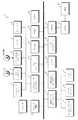
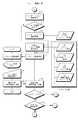
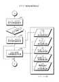
図6は,サーバ1に接続したユーザの装置に表示される画像の遷移を示している。
【0051】
この実施例においては,画像が互いにリンクされており,検索することにより最終的には,ユーザの所望の作者の作品画像をユーザの表示装置に表示するものである。図6において互いに接続されている画像同士がリンクされていることを示している。
【0052】
この実施例においては,次に示す画像がある。
【0053】
ログオン画像50(図42参照)
ユーザがサーバ1にアクセスしたときにそのアクセス権限を確認するための画像である。
【0054】
メニュー画像51(図43参照)
ユーザの表示装置に次に表示させるべき画像を選択するための画像である。
【0055】
カスタマイズ用画像52
ユーザによって画像のカスタマイズを行うための画像である。
【0056】
カテゴリ検索画像53(図45参照)
カテゴリ検索を行うための画像である。
【0057】
キーワード検索画像54(図44参照)
キーワード検索を行うための画像である。
【0058】
アーティスト別一覧画像55
作品画像を見ることのできるアーティストを一覧表示するための画像である。
【0059】
テーマ別一覧画像56
見ることのできる作品画像を,そのテーマ別に一覧表示するための画像である。
【0060】
年代別一覧画像57
見ることのできる作品画像を,年代別に一覧表示するための画像である。
【0061】
国別一覧画像58
見ることのできる作品画像を,作者の国別に一覧表示するための画像である。
【0062】
データ・フォーマット別一覧画像59
見ることのできる作品画像を,データ・フォーマット別に一覧表示するための画像である。
【0063】
検索結果一覧画像60
検索により得られた結果を一覧表示する画像である。
【0064】
作品リスト画像61(図46から図49参照)
アーティストの作品を一覧表示するための画像である。
【0065】
アーティスト画像62
アーティストについての情報を表示する画像である。
【0066】
作品画像63
ユーザが得たいアーティストの作品画像である。
【0067】
この実施例による画像通信システムでは,ユーザの装置がサーバ1とアクセスすると,ユーザにアクセス権限があるかどうかを確認するために,ログオン画像がユーザの装置に表示される。ユーザにアクセス権限があることが確認されるとそのログオン画像とリンクされている次の画像(これをスタート画像という)がユーザの表示装置に表示される。
【0068】
どの画像をスタート画像とするかはユーザによって設定される。ユーザによるスタート画像が設定されていなければ,所定のスタート画像としてメニュー画像がユーザの表示装置に表示される。
【0069】
また,ユーザの表示装置に表示されている画像のリンク先をどの画像とするかもユーザによって設定することができる。たとえば,検索結果一覧画像60がユーザの表示装置に表示されているときにそのリンク先の画像は,作品リスト画像61またはアーティスト画像62であるが,どちらの画像を検索結果一覧画像のリンク先とするかをユーザが決定することができる。
【0070】
図7は,ユーザ情報の一例を示している。
【0071】
ユーザ情報は,サーバ1に接続する受信側の装置の情報である。このユーザ情報は,上述したようにサーバ1のハードディスクに格納されている。ユーザ情報には,ユーザ名,パスワード,スタート画像のスクリプト,検索条件,メニュー画像のスクリプト,カテゴリ検索画像のスクリプト,作品リスト画像のスクリプト,アーティスト画像のスクリプト,作品画像のスクリプトをそれぞれ示すデータなどが含まれている。
【0072】
ユーザ名およびパスワードは,あらかじめ郵送などによりユーザに知らされている。スタート画像などがユーザによってカスタマイズされる。スタート画像などの画像は,スクリプトによってその画像のレイアウトなどが規定される。
【0073】
図7に示すユーザ情報においては,ユーザAからDのスタート画像がカテゴリ検索結果画像に設定されている。そのために,その検索結果を得るための検索条件がユーザ情報に格納されている。
【0074】
図8(A),(B),(C)および(D)は,サーバ1のハードディスクに格納されているアーティスト画像ファイル・グループを示している。アーティスト画像ファイル・グループに一つのIDが付与されている。
【0075】
図8(A)は,アーティスト画像ファイル・グループの管理ファイルである。
【0076】
管理ファイルは,ユーザがサーバ1にアクセスして閲覧したい画像を探すときに用いられる。管理ファイルには,閲覧したい画像の作者の作者名,作者の国籍,作者の生年月日,没年月日,説明文テキスト・ファイルID,ファイル・フォーマット,画像ファイル数,画像ファイル名が含まれている。
【0077】
図8(B)から(D)は,管理ファイルに格納されている画像ファイル名によって表される画像を示している。図8(A)に示す作者画像ファイル管理ファイルに格納されている画像ファイル名によって特定される画像である。
【0078】
図8(B)は,図8(A)に示す管理ファイルの第1の画像ファイル名をもつ画像である。この画像は,画像データ量が最も多く解像度の高いものである。
【0079】
図8(C)は,図8(A)に示す管理ファイルの第2の画像ファイル名をもつ画像である。この画像は,画像データ量が中位の画像であり解像度も中程度である。
【0080】
図8(D)は,図8(A)に示す管理ファイルの第3の画像ファイル名をもつ画像である。この画像は,画像データ量がもっとも少ない画像であり,解像度が低い。
【0081】
アーティスト画像管理ファイル,アーティスト画像ファイルおよび後述するテキスト・ファイルからアーティスト画像62を生成できる。
【0082】
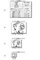
図9(A),(B),(C)および(D)は,作品画像ファイル・グループを示している。この作品画像ファイル・グループも一つのIDを持っている。
【0083】
図9(A)は,作品画像管理ファイルを示している。
【0084】
この管理ファイルもユーザがサーバ1にアクセスして閲覧したい画像を探すときに用いられる。作者画像ファイル管理ファイルには,作者名,画像のタイトル,画像の発表年,画像の作品カテゴリ,説明分テキスト・ファイルID,ファイル・フォーマット,画像ファイル数および画像ファイル名が格納されている。
【0085】
図9(B)および(C)は,作品画像管理ファイルに格納されている画像ファイル名によって表される画像を示している。図9(A)に示す作品画像ファイル管理ファイルに格納されている画像ファイル名によって特定される画像である。
【0086】
図9(B)は,図9(A)に示す作品画像管理ファイルの第1の画像ファイル名をもつ画像である。この画像は,画像データ量が多く,解像度の高いものである。
【0087】
図9(C)は,図9(A)に示す作品画像管理ファイルの第2の画像ファイル名をもつ画像である。この画像は,画像データ量が少なく解像度の低いものである。
【0088】
作品画像管理ファイル,作品画像ファイルおよび後述するテキスト・ファイルから作品画像63を生成できる。
【0089】
図10は(A)および(B)は,テキスト・グループ・ファイルを示している。このテキスト・グループ・ファイルも一つのIDをもっている。
【0090】
図10(A)は,テキスト管理ファイルを示している。
【0091】
このテキスト管理ファイルもユーザがサーバ1にアクセスして閲覧したい画像を探すときに用いられる。タイトル・テキストファイル管理ファイルには,ファイル・フォーマット,テキスト・ファイル数およびテキスト・ファイル名が含まれている。
【0092】
図11(B)は,図11(A)に示すテキスト管理ファイルに格納されているテキスト・ファイル名をもつテキスト・ファイルによって表されるテキストである。
【0093】
検索により図8(A)に示すアーティスト画像管理ファイルが見つかると,そのアーティスト画像管理ファイルに格納されている説明文テキスト・ファイルIDが読み取られる。読み取られた説明文テキスト・ファイルIDをもつテキスト・ファイルが見つけられ(たとえば,図10(B)に示すテキストを表すファイル)見つけられたテキスト・ファイルと画像管理ファイルから,たとえば,後述する図19に示すアーティスト画像が生成される。
【0094】
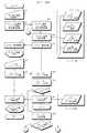
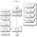
図11は,ユーザの表示装置に表示される画像遷移を示している。
【0095】
この実施例による画像通信システムにおいては,上述したようにサーバ1に最初にアクセスすると,ユーザの表示装置にはログオン画像50が表示される。ログオン画像50によってサーバ1にアクセスしたユーザが権限を有するものかどうかか確認される。権限をもつユーザであることが確認されると,ユーザの表示装置には,スタート画像が表示される。
【0096】
上述したようにスタート画像は,ユーザによって異ならせることができる。たとえば,ユーザAおよびBのスタート画像は,年代別作家一覧の画像57(上述したユーザ情報の検索条件にしたがってカテゴリ検索をした結果,得られる画像の1つである)である。ユーザCおよびDのスタート画像は,テーマ別一覧の画像56(この画像も上述したユーザ情報の検索条件にしたがってカテゴリ検索をした結果,得られる画像の1つである)である。
【0097】
さらに,この実施例による画像通信システムにおいては,上述したように画像のリンク先もユーザによって変えることができる。たとえば,スタート画像として年代別一覧画像57が表示されているユーザAまたはBが「NORI−HANEDA」という文字をクリックすると,ユーザAがクリックしたときには,作品リスト画像61がユーザの表示装置に表示されるが,ユーザBがクリックしたときには,アーティスト画像62がユーザの表示装置に表示される。
【0098】
同様にして,スタート画像としてテーマ別一覧画像56が表示されているユーザCまたはDにおいて「NORI−HANEDA」という文字がクリックされると,ユーザCがクリックしたときには,作品リスト画像61がユーザの表示装置に表示され,ユーザDがクリックしたときにはアーティスト画像62がユーザの表示装置に表示される。
【0099】
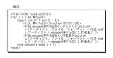
図12から図19は,画像レイアウト,リンク先などを示すスクリプトの一例を示している。
【0100】
図12および図13は,図11に示す年代別一覧画像57を表示するためのスクリプトである。図12は,ユーザAについてのスクリプトであり,図13はユーザBについてのスクリプトである。これらのスクリプトにおいて「function1」がリンク先を示すもので,図12においてfunction1(作品リスト…)となっていることから,年代別一覧画像57から作品リスト画像61にリンクされる。また図13においてfunction1(アーティスト…)となっていることから,年代別一覧画像57からアーティスト画像62にリンクされる。
【0101】
図14および図15は,図11に示すテーマ別一覧画像56を表示するためのスクリプトである。図14はユーザCについてのスクリプトであり,図15はユーザDについてのスクリプトである。ユーザCについてはテーマ別一覧画像56から作品リスト画像61にリンクされている。ユーザDについてはテーマ別一覧画像56からアーティスト画像62にリンクされている。
【0102】
図16は,携帯電話33の表示装置に作品リスト画像を表示するためのスクリプト,図17は携帯型端末装置32の表示装置に作品リスト画像を表示するためのスクリプト,図18はノート型コンピュータ31の表示装置に作品リスト画像(図11に示す作品リスト画像)を表示するためのスクリプト,図19はパーソナル・コンピュータ30の表示装置に作品リスト画像を表示するためのスクリプトである。
【0103】
図12から図19に示すスクリプトにおいて,mod は,剰余を求める演算子,Txt15 は,「現代作家一覧」タイトルテキストファイルID,Txt16 は,「動物画像一覧」タイトルテキストファイルID,function1 は,引数1のページにリンク,引数2は検索条件(functionの小カッコ内においてカンマで区切られた文字列が引数である。引数が複数あるときには最初の引数を引数1,次の引数を引数2という),function3 は,引数1のフォントで表示,function4 は,テキストを引数のポイントで表示,function5 は,先頭から引数1の文字分だけ2倍の大きさで表示,function6 は,引数1以内の文字数で表示,function10は,引数1の色数で表示,function11は,引数1×引数2の大きさで表示,function21は,引数1の色を前景色,引数2の色を背景色にすること,function31は,引数の線幅で枠付け,function32は,引数1の線幅で下線を引くことをそれぞれ表わしている。
【0104】
また,<と>で囲まれた部分はタグとして解釈される。タグによってレイアウトやファイルの配置が実現される。
【0105】
レイアウトには段組とアライメントがある。
【0106】
段組は,次の書式で実現される。
段組の途中でcolumn 1の段を作ると,段組はネスト(階層構造)になる。
アライメントには,左寄せ,センタリング,右寄せがあり,次の書式で実現される。
さらに,複数の段組にわたって表示領域を作成する場合には次のようにする。
【0110】
また,スクリプト内で管理ファイルの内容を取得するため,manageタグを使って次のように変数に値を取り込めるものとする。
#A=<manage(Img1,画像タイトル)>
変数#AにファイルID=Img1であるファイルの画像タイトルを代入する。
【0111】
さらに,スクリプト内に管理ファイルの配置を行いたい場合,次のように記述できるものとする。
<file manage(Img1,画像タイトル)>
ファイルID=Img1の画像ではなく,Img1の画像タイトル(テキスト)をスクリプト内に配置する。
【0112】
また,ここでは,“#”で始まる文字列を変数とする。また,検索結果をスクリプトに反映させるため,下記の検索変数を定義している。
##Count 検索にヒットした件数
##FileID() 検索にヒットしたファイルのファイルID配列
##SearchCondition リンク先のページに渡す検索条件
たとえば,
##SearchCondition=“ファイルフォーマット=作者and生年月日≧1950/1/1”
【0113】
くり返し処理などを行うため,制御タグを定義している。
【0114】
if… then … else … endifタグ
これは条件付き解釈実行のタグである。条件に合致する場合のみ所定範囲のスクリプトを解釈するものである。
【0115】
for … to … nextタグ
繰り返し解釈実行のタグである。
【0116】
ファイルの配置は,基本的にfileタグとファイルIDの指定により実現される。必要に応じて処理を追加することができる。
【0117】
functionパラメータをfileタグに追加することによって処理が追加される。functionパラメータには引数を記述することができる。functionが複数ある場合,左から右の順に解釈される。
【0118】
たとえば,
<file Img1>
ファイルID=Img1の(画像)ファイルの配置を意味する。
<file Txt32 function3(2)>
ファイルID=Txt32 の(テキスト)ファイルの配置を意味する。その際,function 3で指定された処理をかける。例えば,太さ2の枠を付加する。カラー番号2の色で表示,などである。
<file Btn12 function1(I101)>
ファイルID=Btn12 の(ボタン)ファイルを配置を意味する。function 1がリンクの設定であるとすると,I101(ユーザ定義の「作品リスト画像」)へのリンクが実行される。
<file Img2 function4(400,300) function7(256)>
function4(x,y)がx×yの大きさで,function7(i)が色数iで,という意味の処理であれば,画像ファイルImg2は400×300に最も近い画像が選択され,256 色以下のものがなければ減色処理を行ってから表示側に送信される。
【0119】
(2) 通信処理
図20から図41は,サーバ1とユーザの装置との間での通信の処理手順(所望の作品画像の検索)を示すフローチャートである。図42から図57は,ユーザの装置に接続されている表示装置に表示される画像の一例である。図42から図57においては,図47から図49および図57を除いてテキスト・データによって表される画像が示されているがユーザの装置がテキスト以外の画像(絵を表す画像)を表示できる場合には,それらの絵などを含む画像が表示される。
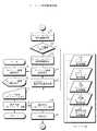
【0120】
I.ログオン処理
まず,ログオン処理が行われる。
【0121】
ユーザの装置によってログオン画像の送信要求が入力される(ステップ51)。すると,ログオン要求,ユーザの装置にインストールされている(もしくはインストールされていない)ブラウザの情報(どのようなブラウザがインストールされているか,またはブラウザがインストールされていないか)およびユーザの装置についての情報(たとえば,ユーザの装置に接続されている表示装置の表示可能な色数,表示可能な画像の大きさなど)が,ユーザの装置からサーバ1に送信される(ステップ52)。
【0122】
ユーザの装置から送信されたログオン画像要求,ブラウザ情報および装置情報がサーバ1によって受信される(ステップ201 )。ユーザの装置から送信されたブラウザ情報および装置情報にもとづいて,ユーザの装置に接続されている表示装置に表示可能な適切なログオン画像を表す画像データががサーバ1のハードディスクから選択される(ステップ202 )。サーバのハードディスクには,テキスト・ログオン画像,PC(パーソナル・コンピュータ)用ログオン画像(必要に応じてパーソナル・コンピュータ用ログオン画像とノート型コンピュータ用ログオン画像とが格納される),PDA用ログオン画像および携帯電話用ログオン画像をそれぞれ表す画像データが格納されている。ユーザの装置に合った適切な画像データがサーバ1において選択される。選択されたログオン画像を表す画像データがサーバ1からユーザの装置に送信される(ステップ203 )。
【0123】
ユーザの装置において,サーバ1から送信されたログオン画像を表す画像データが受信される(ステップ53)。受信した画像データは,表示装置に与えられ,ログオン画像が表示される(ステップ54,図42参照)。
【0124】
図42は,テキスト・ログオン画像の一例である。ユーザの装置にブラウザがインストールされていないときにはテキスト・ログオン画像が表示される。テキスト・ログオン画像においては,ユーザ名およびパスワードの入力指示が表示されている。ユーザは,この指示にしたがって,ユーザ名および自分のパスワードを入力する(ステップ55)。入力されたユーザ名およびパスワードがユーザの装置からサーバ1に送信される(ステップ56)。
【0125】
携帯電話用のログオン画像であればテキスト・ログオン画像にクリップ・アートなどの少しの飾りが付加される。PDA用のログオン画像であれば携帯電話用のログオン画像にさらに飾りが付く。PC用のログオン画像であれば,PDA用のログオン画像にさらに飾りが付くこととなる。サーバにアクセスした装置に適した(ブラウザに適した)ログオン画像がユーザの装置に接続されている表示装置に表示されることとなる。
【0126】
サーバ1において,ユーザの装置から送信されたユーザ名およびパスワードが受信される(ステップ204 )。サーバ1のハートディスクに格納されているユーザ情報が参照される。ユーザの装置から送信されたユーザ名およびパスワードがユーザ情報に格納されているか,送信されたユーザ名とパスワードが合っているかどうかがチェックされる(ステップ205 )。
【0127】
ユーザ名およびパスワードが一致しなければ(ステップ206 でNO),サーバ1のハードディスクに格納されているテキスト・ログオン失敗画像を表すデータが読み出される。読み出された画像データは,サーバ1からユーザの装置に送信される(ステップ207 )。
【0128】
ユーザの装置において,ログオン失敗画像を表すデータが受信される(ステップ57)。画像データは,ユーザの装置に接続されている表示装置に与えられる。これにより,ログオン失敗画像がユーザの装置に接続されている表示装置に表示される(ステップ58)。
【0129】
この実施例による画像通信システムは,ログオン画像の次にユーザの装置に接続されている表示装置に表示されるスタート画像をユーザが設定しておくことができる。このために,ユーザ名およびパスワードが一致すると(ステップ206 でYES),ユーザ情報(図7参照)が参照され,ログオンしたユーザのスタート画像がユーザによって設定されているかどうかがチェックされる(ステップ209 )。
【0130】
スタート画像が設定されていると(ステップ209 でYES),図22に示すユーザ・スタート画像処理に移行する。
【0131】
II.ユーザ・スタート画像処理
スタート画像処理において,ユーザ情報を参照して,サーバ1にアクセスしているユーザのスタート画像を表すスタート画像情報(図7のユーザ情報のうちスタート画像の項目に格納されている情報)が読み出される(ステップ219 )。スタート画像を表すスタート画像情報が読み出されると,図32に示すリンク処理に移行する。ユーザ情報から読み出されたスタート画像情報にもとづいて,スタート画像がどの画像かがチェックされる(ステップ311 から320 )。設定されている画像がスタート画像としてログオン画像の次の画像としてユーザの装置に接続されている表示装置に表示される。
【0132】
いずれの画像にもスタート画像が該当しなければ,エラーであるとして図23に示すエラー画像処理に移行する。
【0133】
III.エラー画像処理
エラー画像処理においては,サーバ1のハードディスクに記録されているエラー画像を表す画像データのうちユーザの装置およびブラウザに適したエラー画像が選択される(ステップ221 )。エラー画像がサーバ1において生成され,そのエラー画像を表すデータがサーバ1からユーザの装置に送信される(ステップ223 )。
【0134】
ユーザの装置において,サーバ1から送信されたエラー画像を表すデータが受信されると(ステップ71),そのエラー画像を表すデータがユーザの装置に接続されている表示装置に与えられる。ユーザの表示装置にエラー画像が表示される(ステップ72)。
【0135】
エラー画像には,メニュー・ボタンも含まれておりこのメニュー・ボタンがユーザによって選択されると(ステップ73),メニュー・ボタンが選択されたことを示すデータがユーザの装置からサーバ1に送信される(ステップ74)。
【0136】
メニュー・ボタンが押されたことを示すデータがサーバ1において受信されると(ステップ223 ),図21に示すメニュー画像処理に移行する。
【0137】
ユーザによってスタート画像が設定されていないと(図20ステップ209 においてNO),図21に示すメニュー画像処理に移行する。
【0138】
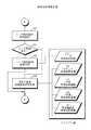
IV.メニュー画像処理
この実施例における画像通信システムでは,上述したようにユーザの表示装置に表示させる画像をユーザ自身がカスタマイズすることができる。ユーザ情報が検索され(ステップ211 ),メニュー画像がユーザによってカスタマイズされているかどうかがチェックされる。図7に示すユーザ情報において「なし」と表示されているとユーザによってカスタマイズされていないことを示している。カスタマイズされていないと,所定の画像が表示されることとなる。
【0139】
ユーザによってメニュー画像がカスタマイズされていないと(ステップ212 でNO),所定のメニュー画像を表すデータのうち,サーバ1にアクセスしているユーザの装置およびブラウザに適したデータがサーバ1のハードディスクから読み出される(ステップ214 )。読み出されたメニュー画像を表すデータがサーバ1からユーザの装置に送信される(ステップ215 )。
【0140】
ユーザによってメニュー画像がカスタマイズされていると(ステップ212 でYES),そのカスタマイズされているメニュー画像(ユーザ画像)を表すデータがサーバ1のハードディスクから出される。読み出されたメニュー画像を表すデータがサーバ1からユーザの装置に送信される(ステップ215 )。
【0141】
ユーザによってメニュー画像がカスタマイズされている場合でも,そのカスタマイズされたメニュー画像を表示できない装置によって,サーバ1にアクセスしていることがある。その場合にはカスタマイズされたメニュー画像を表わすデータのうちユーザの装置が表示可能なデータ(たとえば,テキスト・データ)がサーバ1からユーザの装置に送信される。
【0142】
ユーザの装置において,サーバ1から送信されたメニュー画像を表すデータが受信されると(ステップ61),そのメニュー画像を表すデータがユーザの表示装置に与えられる。ユーザの表示装置には,図43に示すようにメニュー画像が表示される(ステップ62)。
【0143】
メニュー画像には,「1.カスタマイズ用画像」,「2.カテゴリ検索画像」,「3.キーワード検索画像」の項目が表示されている。ユーザは,これらの項目の中から表示装置に表示させる画像の項目を選択する(ステップ63)。選択された項目を表すデータがユーザの装置からサーバ1に送信される(ステップ64)。
【0144】
サーバ1において,ユーザの装置から送信された項目を表すデータが受信されると(ステップ216 ),それが「1.カスタマイズ用画像」,「2.カテゴリ検索画像」および「3.キーワード検索画像」の中のどの画像の表示要求かがチェックされる(ステップ217 ,218 )。
【0145】
ユーザが「1.カスタマイズ用画像」を選択したのであれば(ステップ217 でYES),図33に示すカスタマイズ・メニュー処理が行われる。
【0146】
V.カスタマイズ・メニュー処理
図33を参照して,ユーザの装置およびブラウザに適したカスタマイズ・メニュー画像を表すデータがサーバ1から読み出される(ステップ331 )。読み出されたデータがサーバ1からユーザの装置に送信される(ステップ332 )。
【0147】
ユーザの装置において,サーバ1から送信されたカスタマイズ・メニュー画像を表すデータが受信されると(ステップ101 ),ユーザの表示装置には,図50に示すようにカスタマイズ・メニュー画像が表示される(ステップ102 )。カスタマイズ・メニュー画像には,ユーザがカスタマイズする画像の選択指示が表示されている。カスタマイズできる画像には,ここでは「1.スタート画像」(どの画像をスタート画像とするか,すなわち,ログオン画像の次の表示される画像を設定),「2.メニュー画像」,「3.カスタマイズ用画像」,「4.カテゴリ検索画像」,「5.キーワード検索画像」,「6.作品リスト画像」,「7.アーティスト画像」がある。ユーザは,これらの画像を示す項目の中からカスタマイズする画像を選択する(ステップ103 )。選択した項目(画像)を示すデータがユーザの装置からサーバ1に送信される(ステップ104 )。
【0148】
ユーザにおいて選択した項目を示すデータがサーバ1において受信されると(ステップ333 ),スタート画像の設定を示すものかどうかがチェックされる(ステップ334 )。
【0149】
ユーザによって選択された項目がスタート画像の設定を示すものであれば(ステップ334 でYES),図34に示すスタート画像設定処理に移行する。
【0150】
VI.スタート画像設定処理
図34を参照して,ユーザの装置およびブラウザに適したスタート画像設定画像がサーバ1のハードディスクから読み出される(ステップ341 )。読み出されたスタート画像設定画像を表すデータがサーバ1からユーザの装置に送信される(ステップ342 )。
【0151】
ユーザの装置において,サーバ1から送信されたスタート画像設定画像を表すデータが受信されると(ステップ111 ),そのスタート画像設定画像を表すデータがユーザの表示装置に与えられる。スタート画像設定画像がユーザの表示装置に表示される(ステップ112 )。
【0152】
図51は,ユーザの表示装置に表示されるスタート画像設定画像の一例である。
【0153】
スタート画像設定画像には,スタート画像選択の指示および選択できるスタート画像の項目が表示されている。この実施例においては,スタート画像は,「1メニュー画像」,「2.カスタマイズ画像」,「3.カテゴリ検索画像」,「4.キーワード検索画像」,「5.カテゴリ検索結果画像」,「6.作品リスト画像」,「7.アーティスト画像」を選択することができ,これらの項目がスタート画像設定画像に表示されている。ユーザによっていずれかの項目が選択される(ステップ113 )。選択された項目を表すデータがユーザの装置からサーバ1に送信される(ステップ114 )。
【0154】
サーバ1において,ユーザの装置から送信された選択された項目を表すデータが受信される(ステップ343 )。受信したデータにもとづいて,スタート画像がユーザ情報の対応するスタート画像項目に書き込まれる(ステップ344 )。たとえば,ユーザAがスタート画像に「5.カテゴリ検索結果画像」を選択したときには,図7に示すユーザ情報のスタート画像の項目に「カテゴリ検索結果」と書き込まれる。その後,図33に示すカスタマイズ・メニュー画像処理に戻る。
【0155】
ユーザの表示装置に図50に示すカスタマイズ・メニュー画像が表示されているときにスタート画像のカスタマイズ以外が選択されると(ステップ334 でNO),図35に示す画像編集メイン処理に移行する。画像編集メイン処理は,画像編集を,項目を追加することにより行うかスクリプト編集により一括して行うかを設定するものである。
【0156】
VII.画像編集メイン処理
画像編集メイン処理においては,まず,サーバ1においてユーザの装置およびそのブラウザに適した画像編集画像を表すデータが読み出される(ステップ351 )。読み出された画像編集画像を表すデータがサーバ1からユーザの装置に送信される(ステップ352 )。
【0157】
ユーザの装置においてサーバ1から送信された画像編集画像を表すデータが受信されると(ステップ121 ),その画像編集画像を表すデータがユーザの表示装置に与えられる(ステップ122 )。ユーザの表示装置には,図52に示すような画像編集画像が表示される(ステップ123 )。画像編集画像には,「項目の追加またはスクリプト編集しますか。項目の追加のときは,追加する項目を入力してください。」と表示される。
【0158】
ユーザは,画像編集画像の表示にしたがって,項目の追加またはスクリプト編集のいずれを行うかの指令をユーザの装置に入力する。また,項目の追加ならば,どの項目を追加するかが入力される(ステップ124 )。ユーザによって選択された項目の追加(および追加する項目名)またはスクリプト編集を示す選択データがユーザの装置からサーバ1に送信される(ステップ124 )。
【0159】
サーバ1において,ユーザの装置から送信された選択データが受信されると(ステップ353 ),ページ編集終了か(ステップ354 ),スクリプト編集か(ステップ355 ),項目の追加かどうかが判定される。
【0160】
画像編集終了であれば(図52においては省略してあるが画像編集修了もユーザが指定できる)(ステップ354 でYES),図33に示すカスタマイズ・メニュー画像処理に移行する。
【0161】
スクリプト編集であれば(ステップ355 でYES),図36に示すスクリプト編集処理に移行する。
【0162】
VIII.スクリプト編集処理
図36を参照して,スクリプト編集処理であればユーザの装置およびブラウザに適したスクリプト編集画像を表すデータがサーバのハードディスクから読み出される(ステップ361 )。また,ユーザがカスタマイズしようとしている編集画像についてのスクリプトが初期化される(ステップ362 )。読み出されたデータがサーバ1からユーザの装置に送信される(ステップ363 )。
【0163】
ユーザの装置において,サーバから送信されたスクリプト編集画像を表すデータが受信されると(ステップ131 ),ユーザの表示装置にそのスクリプト編集画像を表すデータが与えられる。ユーザの装置には,図53に示すようなスクリプト編集画像が表示される(ステップ132 )。
【0164】
スクリプト編集画像には,「スクリプトにより一括編集を行います。スクリプトを入力して下さい。」との文字が表示される。ユーザによってスクリプトが入力されると(ステップ133 ),その入力されたスクリプトがスクリプト編集画像上に表示されていく。ユーザによって入力されたスクリプトを示すデータは,ユーザの装置からサーバ1に送信される(ステップ134 )。
【0165】
サーバ1において,ユーザの装置から送信されたスクリプトを示すデータが受信されると(ステップ364 ),スクリプト編集中止要求かどうかが判定される(ステップ365 )(図53においては省略しているが,スクリプト編集中止もユーザが入力できる)。
【0166】
スクリプト編集中止要求であれば(ステップ365 でYES),図35に示す画像編集メイン処理に戻る。
【0167】
スクリプト編集中止要求でなければ(ステップ365 でNO),送信されたスクリプトを表すデータにエラーがあるかどうかがチェックされる(ステップ366 ,367 )。
【0168】
エラーがあれば(ステップ367 でYES),エラー・メッセージをスクリプト・エラーとし,その内容をスクリプトとして書き込む(ステップ368 )。ユーザから送信されたスクリプトを,ユーザに送信するように設定される(ステップ369 )。ユーザから送信されたスクリプトがユーザに返される。
【0169】
スクリプト・エラーが発生しなければ(ステップ367 でNO),編集されたスクリプトによって規定される編集画像を構成する画像を表すファイルがサーバ1のハードディスクに格納されていない新規なものかどうかが判定される(ステップ370 )。
【0170】
新規ファイルがなければ(ステップ370 でNO),図38に示すカスタマイズ内容反映処理に移行する。
【0171】
IX.カスタマイズ内容反映処理
ユーザから送信されたスクリプトにしたがって,ユーザによって選択された画像を表すデータが更新される。更新されたデータがサーバ1のハードディスクに格納される(ステップ392 )。また,カスタマイズされた画像についてのユーザ情報が更新される(ステップ393 )。その後,図31に示すカスタマイズ処理に移行する。
【0172】
新規ファイルがあると(ステップ370 でYES),図37に示す新規ファイル送信処理に移行する。
【0173】
X.新規ファイル送信処理
サーバにおいて,ユーザの装置およびブラウザに適したファイル送信画像を表すデータが読み出される(ステップ381 )。エラー・メッセージが初期化され,送信ファイル・リストが全新規ファイルに設定される(すべての新規ファイルをサーバに送信するように設定)(ステップ382 )。ファイル送信画像を表すデータ,エラー・メッセージおよび送信ファイル・リストがサーバ1からユーザの装置に送信される(ステップ383 )。
【0174】
ファイル送信画像を表すデータ,エラー・メッセージおよび送信ファイル・リストがユーザの装置において受信されると(ステップ141 ),これらの受信したデータがユーザの表示装置に送信される(ステップ142 )。ユーザの装置には,図54に示すように,ファイル送信画像が表示される(ステップ142 )。ユーザによって新規画像ファイルを示すファイル名が入力される(ステップ143 )。入力されたファイル名がファイル送信画像に表示される。入力されたファイル名によって特定されるファイルがユーザの装置から読み出され,サーバ1に送信される(ステップ144 )。
【0175】
サーバ1において,ユーザの装置から送信されたファイルは,サーバ1によって受信される(ステップ384 )。ユーザからスクリプト編集中止要求があったかどうかがチェックされる(ステップ385 )(図54においては図示を省略してあるがスクリプト編集中止要求もユーザは設定できる)。
【0176】
スクリプト編集中止要求があれば(ステップ385 でYES),図35に示す画像編集メイン処理に移行する。
【0177】
スクリプト編集中止要求がなければ(ステップ385 でNO),送信されたファイルにエラーがあるかどうかがチェックされる(ステップ386 ,387 )。
【0178】
エラーが含まれていると(ステップ387 でYES),エラー・メッセージがファイル転送エラーと書き込まれ(ステップ388 ),送信ファイル・リストがエラー・ファイルとされ,エラーとなった新規ファイルを再度送信するように設定される(ステップ389 )。その後ステップ383 からの処理が繰り返され,エラー・メッセージがサーバ1からユーザの装置に送信される。
【0179】
エラーが含まれていなければ(ステップ387 でNO),図38に示すカスタマイズ内容反映処理に移行する。
【0180】
カスタマイズ内容反映処理において,サーバ1において受信した新規ファイルがサーバに格納される(ステップ391 )。その後,選択された画像について行われたカスタマイズ後の画像を表すデータがサーバ1のハードディスクに格納される(ステップ392 )。また,ユーザ情報が更新される(ステップ393 )。その後,図33に示すカスタマイズ・メニュー画像処理が繰り返される。
【0181】
図21に戻って,メニュー画像においてユーザがカテゴリ検索画像を設定していると(ステップ218 でYES),図26に示すカテゴリ検索画像処理に移行する。
【0182】
XI.カテゴリ検索画像処理
まず,ユーザがカスタマイズした固有のカテゴリ検索画像(ユーザ画像)を表すデータがサーバ1のハードディスクに格納されているかどうかがユーザ情報を参照して確認される(ステップ251 )。ユーザ固有のカテゴリ検索画像を表すデータがあると(ステップ252 でYES),そのユーザ固有のカテゴリ検索画像を表すデータがハードディスクから読み出される(ステップ253 )。ユーザ固有のカテゴリ検索画像を表すデータがサーバ1に格納されていないと(ステップ252 でNO),ユーザの装置およびブラウザに適したカテゴリ検索画像を表すデータがサーバ1のハードディスクから読み出される(ステップ255 )。読み出されたカテゴリ検索画像を表すデータがサーバ1からユーザの装置に送信される(ステップ254 )。
【0183】
ユーザの装置において,サーバ1から送信されたカテゴリ検索画像を表すデータが受信されると(ステップ81),その受信したデータはユーザの表示装置に与えられる(ステップ82)。ユーザの表示装置には,図45に示すカテゴリ検索画像が表示されることとなる。カテゴリ検索画像には,検索すべきカテゴリが表示される。図45に示す例では,「1.アーティスト別」,「2.テーマ別」,「3.年代別」「4.国別」および「5.データ・フォーマット別」がある。ユーザによっていずれかのカテゴリが選択される(ステップ83)。選択されたカテゴリを表すデータは,ユーザの装置からサーバ1に送信される(ステップ84)。
【0184】
サーバ1において受信されたカテゴリを表すデータにもとづいて(ステップ256 ),作品画像の検索処理が実行される(ステップ257 )。その後,図27に示すカテゴリ検索結果処理に移行する。
【0185】
XII.カテゴリ検索結果処理
図27を参照して,ユーザがカスタマイズしているカテゴリ検索結果画像がユーザ情報において検索される(ステップ261 )。ユーザがカテゴリ検索結果画像についてカスタマイズしていれば,ユーザのカスタマイズ画像(ユーザ画像)があるので,そのユーザについてのカテゴリ検索結果画像がサーバ1のハードディスクから探し出される(ステップ263 )。ユーザがカテゴリ検索結果画像についてカスタマイズしていなければ,デフォルトの検索結果画像のうち,ユーザの装置およびブラウザに適した検索結果画像がサーバ1のハードディスクから読み出される(ステップ264 )。いずれにしても,検索結果画像がサーバ1のハードディスクから読み出されると,図31に示す編集画像作成処理に移行する。
【0186】
VIII.編集画像作成処理
図31を参照して,作成すべき編集画像に適した追加プログラムがサーバ1のハードディスクから読み出される(ステップ301 )。この場合であれば,検索結果画像を作成するために適した追加プログラム(たとえば,ユーザがスクリプトにおいて定義した処理を実行するためのプログラムなど)がサーバ1のハードディスクから読み出される。検索結果画像を作成するために必要なファイル(画像ファイル,文章(テキスト)ファイル,ボタン・ファイル,音ファイルなど)がサーバ1のハードディスクから読み出され,検索結果画像が作成される(ステップ302 )。作成された検索結果を表す編集画像を表すデータがサーバ1からユーザの装置に送信される(ステップ303 )。
【0187】
ユーザの装置において,サーバ1から送信された検索結果を表す編集画像データが受信される(ステップ91)。検索結果を表す編集画像データがユーザの表示装置に与えられることにより,ユーザの表示装置に検索結果を示す編集画像が表示される(ステップ92)。検索結果画像に表示されているリンク先(画像,テキスト,URL名など)がユーザによって指定される(ステップ93)。指定されたリンク先を示すデータがユーザの装置からサーバ1に送信される(ステップ94)。
【0188】
サーバ1においてユーザの装置から送信されたリンク先を示すデータが受信される(ステップ304 )。図30に示すリンク処理に移行し,ユーザの所望の画像を表すデータがサーバ1からユーザの装置に送信されることとなる。
【0189】
図21に戻って,ユーザの表示装置に表示されているメニュー画像(図43参照)においてユーザが「3.キーワード検索画像」が選択したときには,図24に示すキーワード検索画像処理に移行する(ステップ28でNO)。
【0190】
XIV.キーワード検索画像処理
図24を参照して,ユーザによってカスタマイズされているキーワード検索画像がユーザ情報にもとづいて検索される(ステップ231 )。ユーザによってカスタマイズされているキーワード検索画像(ユーザ画像)があれば(ステップ232 でYES),その画像を表わすデータがサーバ1のハードディスクから読み出される(ステップ233 )。ユーザによってカスタマイズされているキーワード検索画像がなければ(ステップ232 でNO),デフォルトのキーワード検索画像がサーバ1のハードディスクから読み出される(ステップ235 )。いずれにしても,サーバ1のハードディスクから読み出されたキーワード検索画像を表すデータがサーバ1からユーザの装置に送信される(ステップ234 )。
【0191】
ユーザの装置において,サーバ1から送信されたキーワード検索画像を表すデータが受信される(ステップ75)。受信されたキーワード検索画像を表すデータは,ユーザの表示装置に与えられ図44に示すようなキーワード検索画像が表示される(ステップ76)。
【0192】
キーワード検索画像には,「キーワードを入力して下さい」という指示が表示される。この指示にしたがって,ユーザは,キーワードを入力する(ステップ77)。入力されたキーワードがユーザの表示装置に表示される。入力されたキーワードは,ユーザの装置からサーバ1に送信される(ステップ78)。
【0193】
サーバ1においてユーザの装置から送信されたキーワードを表すデータが受信される(ステップ236 )。サーバにおいて,受信されたキーワードにもとづいて検索処理が実行される(ステップ237 )。すると,図25に示す検索結果画像処理に移行する。
【0194】
XV.検索結果画像処理
図25において,ユーザによってカスタマイズされている検索結果画像があるかどうかがユーザ情報において検索される(ステップ241 )。検索によりユーザによってカスタマイズされている検索結果画像がある場合には(ステップ242 でYES),その検索結果画像を表すデータがサーバ1のハードディスクから読み出される(ステップ243 )。ユーザによってカスタマイズされている検索結果画像がない場合には,(ステップ242 でNO),ユーザの装置およびブラウザに適した所定の検索結果画像を表すデータがサーバのハードディスクから読み出される(ステップ244 )。その後,図31に示す編集画像作成処理に移行し,上述したカテゴリ検索画像作成処理と同様にしてキーワード検索結果画像が作成され,ユーザの装置に送信される。
【0195】
ユーザの表示装置には,キーワード検索結果画像が表示されることとなる。
【0196】
リンク処理において(図32参照)において,作品リスト画像をユーザの表示装置に表示させるときには(ステップ318 でYES),図28に示す作品リスト処理に移行する。
【0197】
XVI.作品リスト処理
図28を参照して,ユーザによってカスタマイズされた作品リスト画像がユーザ情報において検索される(ステップ271 )。ユーザによってカスタマイズされた作品リスト画像(ユーザ画像)がサーバ1にあれば(ステップ272 でYES),その作品リスト画像を表すデータがサーバ1のハードディスクから読み出される(ステップ273 )。ユーザによってカスタマイズされた作品リスト画像がサーバ1に無ければ(ステップ272 でNO),サーバ1のハードディスクに格納されている所定の作品リスト画像のうち,ユーザの装置に適した作品リスト画像を表すデータが読み出される(ステップ274 )。その後図31に示す編集画像作成処理に移行し,作品リスト画像を表すデータが作成される。作成された作品リスト画像を表すデータがサーバ1からユーザの装置に送信され,ユーザの表示装置に,作品リスト画像が表示される。
【0198】
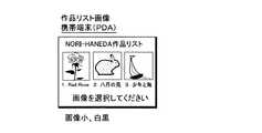
図46から図49は,作品リスト画像の一例である。
【0199】
図44は,ユーザの装置が携帯電話(またはユーザの装置がテキストのみを表示できる装置)であるときに表示される作品リスト画像である。携帯電話では,画像を表示することが比較的難しい。このために,携帯電話の表示装置に適した作品リスト画像が表示される。
【0200】
図46は,ユーザの装置が携帯端末であるときに表示される作品リスト画像である。携帯端末は,画像を表示することはできるが表示装置の表示画面は,あまり大きくない。このため,あまり大きくない作品リスト画像携帯端末の表示装置に表示される。
【0201】
図47は,ユーザの装置パーソナル・コンピュータであり,そのパーソナル・コンピュータに小さな表示装置が接続されているときに,表示される作品リスト画像である。比較的大きな作品リスト画像が表示される。
【0202】
図49は,ユーザの装置パーソナル・コンピュータであり,大きな表示画面をもつ表示装置が接続されているときに,表示される作品リスト画像である。大きな表示画面に表示されるのに適した作品リスト画像が表示される。
【0203】
図47に示す作品リスト画像においては小さい画像が用いられており,図48に示す作品リスト画像においては中位の大きさの画像が用いられており,図49に示す作品リスト画像においては大きい画像が用いられている。このように,ユーザの装置に応じて大きさの異なる画像により構成される作品リスト画像を表わすデータが,サーバ1からユーザの装置に送信される。また必要に応じて色数の減色処理も行なわれることとなろう。
【0204】
XVII.アーティスト画像処理
図29は,アーティスト画像処理を示している。
【0205】
アーティスト画像にリンクされるときには,サーバ1のハードディスクにおいてユーザによってカスタマイズされたアーティスト画像が検索される(ステップ281 )。ユーザによってカスタマイズされたアーティスト画像があれば(ステップ282 でYES),そのカスタマイズされた画像を表すデータがサーバ1のハードディスクから読み出される(ステップ283 )。ユーザによってカスタマイズされたアーティスト画像がなければ(ステップ282 でNO),ユーザの装置およびブラウザに適したアーティスト画像を表すデータがサーバ1のハードディスクから読み出される(ステップ284 )。図31に示す編集画像作成処理において読み出されたデータからアーティスト画像を表すデータが作成される。作成されたアーティスト画像を表すデータがユーザの装置に送信され,ユーザの装置およびブラウザに適したアーティスト画像またはユーザによってカスタマイズされたアーティスト画像がユーザの表示装置に表示される。
【0206】
XVIII.作品画像処理
図30は,作品画像処理を示している。
【0207】
作品画像にリンクされるときには,サーバ1のハードディスクにおいてユーザよってカスタマイズされた作品画像が検索される(ステップ291 )。ユーザによってカスタマイズされた作品画像(ユーザ画像)があれば(ステップ292 でYES),そのカスタマイズされた作品画像を表すデータがサーバ1のハードディスクから読み出される(ステップ293 )。ユーザによってカスタマイズされた作品画像がなければ(ステップ292 でNO),デフォルトの作品画像のうちユーザの装置およびブラウザに適した作品画像がサーバ1のハードディスクから読み出される(ステップ294 )。いずれにしても,サーバ1のハードディスクから読み出された作品画像についての処理にもとづいて,作品画像を表すデータが生成され,ユーザの装置に送信される。ユーザの表示装置に,ユーザによってカスタマイズされた作品画像またはユーザの装置およびブラウザに適した作品画像が表示される。
【0208】
作品画像,アーティスト画像などを表示するときには上述したように図8(A)〜図10(A)および(B)に示したように各ファイル・グループが検索され,該当するファイルが用いられるのはいうまでもない。
【0209】
図35に戻って,スクリプト編集でなければ,画像の項目を追加することにより画像のカスタマイズを行うものである(ステップ355 でNO)。
【0210】
まず,スクリプトが初期化される(ステップ356 )。その後,画像項目追加処理に移行する(ステップ357 )。画像項目追加処理については,次に述べる。画像項目追加処理が終了するとその画像項目追加処理において新規ファイルが追加されたかどうかがチェックされる(ステップ358 )。新規ファイルが追加されていると(ステップ358 でYES),図37に示す新規ファイル追加処理に移行する。新規ファイルが追加されていないと(ステップ358 でNO),図38に示すカスタマイズ内容反映処理に移行する。いずれにしても上述したように,カスタマイズによって表示項目が追加されたことによりユーザ情報が更新される。
【0211】
XIX.画像項目追加処理
図38は,画像項目追加処理を示すフローチャートである。
【0212】
ユーザの装置およびブラウザに適した追加項目選択画像を表すデータがサーバ1のハードディスクから読み出される(ステップ401 )。読み出された追加項目選択画像を表すデータがサーバ1からユーザの装置に送信される(ステップ402 )。
【0213】
ユーザの装置において,追加項目選択画像を表すデータが受信され(ステップ151 ),ユーザの表示装置に与えられる(ステップ152 )。ユーザの表示装置には,図55に示すような追加項目選択画像が表示される(ステップ152 )。
【0214】
追加項目選択画像には,「レイアウトの追加またはファイル配置を行いますか」の質問のテキストが表示される。ユーザは,このテキストに応じて,「レイアウトの追加」または「ファイル配置」のうち所望の処理を選択する(ステップ153 )。選択された内容を表すデータがユーザの装置からサーバ1に送信される(ステップ154 )。
【0215】
サーバ1において,ユーザの装置から送信された選択の内容を表すデータが受信される(ステップ403 )。受信された内容が画像編集中止要求であれば(ステップ404 でYES)(図55においては画像編集中止および後述する画像編集終了について図示を省略しているが,これらの中止または終了をユーザは設定できる),図35に示す画像編集メイン処理に移行し,必要であれば再び画像編集処理が行われる。受信した内容が画像編集終了要求であれば(ステップ405 でYES),画像要素追加処理は終了する。受信した内容がレイアウト追加処理であれば(ステップ406 でYES),図40に示すレイアウト追加処理に移行する(ステップ407 )。受信した内容がファイル配置処理であれば(ステップ406 でNO),図41に示すファイル配置処理に移行する(ステップ408 でNO)。
【0216】
XX.レイアウト追加処理
図40を参照して,レイアウト追加処理について説明する。
【0217】
ユーザの装置およびブラウザに適したレイアウト選択画像を表すデータがサーバ1のハードディスクから読みだされる(ステップ411 )。読みだされたデータがサーバ1からユーザの装置に送信される(ステップ412 )。
【0218】
ユーザの装置において,サーバ1から送信されたレイアウト選択画像を表すデータが受信される(ステップ161 )。レイアウト選択画像を表すデータがユーザの表示装置に与えられ,図56に示すようなレイアウト選択画像が表示される(ステップ162 )。レイアウト選択画像には,「変更するレイアウトを入力して下さい」との指示が表示される。ユーザは,この指示にしたがって変更するレイアウトたとえば,テキストの右寄せ,左寄せ,センタリング,段組などを入力する(ステップ163 )。入力されたレイアウト指示がユーザの装置からサーバ1に送信される(ステップ164 )。
【0219】
サーバ1において,ユーザの装置から送信されたレイアウト指示が受信される(ステップ413 )。受信された指示が画像編集中止要求であれば図35に示す画像処理メイン処理に移行する(ステップ414 でYES)。受信した指示がレイアウト選択中止であれば(ステップ415 でYES),レイアウト追加処理は終了する(図56においては図示を省略しているが画像編集中止またはレイアウト選択中止をユーザは設定できる)。レイアウト選択中止処理でなければ(ステップ415 でNO),レイアウト追加処理の対象となっている画像のスクリプトに,ユーザによって指示されたレイアウト追加のタグが追加される(ステップ416 )。その後,上述した画像要素追加処理において,その追加されたタグによってレイアウトが指定される要素(画像,テキスト,ボタン,など)がスクリプトに追加される(ステップ417 )。
【0220】
XXI.ファイル配置処理
図41は,ファイル配置処理を示すフローチャートである。
【0221】
ユーザの装置およびブラウザに適したファイル配置画像を表すデータがサーバ1のハードディスクから読みだされる(ステップ421 )。読みだされたデータがサーバ1からユーザの装置に送信される(ステップ422 )。
【0222】
ユーザの装置において,サーバ1から送信されたファイル配置画像を表すデータが受信される(ステップ171 )。ユーザの表示装置に,図57に示すようなファイル配置画像が表示される(ステップ172 )。
【0223】
ファイル配置画像には,次の各領域が含まれている。
【0224】
配置ファイル領域501;
この配置ファイル領域には,タイトル・テキストファイルを配置させるときにユーザによってチェックさせる領域502 ,作者画像ファイルを配置させるときにユーザによってチェックさせる領域503 および作品画像ファイルを配置させるときにユーザによってチェックさせる領域504 が含まれている。ユーザが配置させるべきファイルに対応した領域502 ,503 および504 がユーザによってチェックされる。
【0225】
表示対象領域505;
配置ファイル領域501 において選択されたファイル(管理ファイル)のうち表示させるべき対象(たとえば,画像,作者名,タイトルなど)を指定するためものである。
【0226】
表示オプション領域510;
この表示オブション領域510 には,さらに,次の領域が含まれている。
【0227】
リンク設定領域511;
リンク先を設定する領域である。
【0228】
検索条件領域512;
検索によりヒットさせるべき検索対象を指定するためものである。たとえば,ある年代以上の作品のみを検索対象とするときに,その年代がユーザによって入力される。
【0229】
表示領域513および514;
画像,テキスト,ボタンを表示する領域を指定するものである。領域513 に横のサイズが入力され,領域514 に縦のサイズが入力される。
【0230】
色指定領域515;
表示すべき色を特定する色番号を入力する領域である。
【0231】
色数指定領域516;
表示すべき色数を指定する領域である。たとえば, 256色,1600万色などが入力される。
【0232】
フォント指定領域517;
表示されるフォントを指定する領域である。たとえば,ゴシック体,明朝体と入力される。
【0233】
ポイント指定領域518;
文字の大きさを指定する領域である。
【0234】
強調指定入力519;
文字を強調するときに入力するものである。たとえば,下線,文字の反転,中抜き文字などが入力される。
【0235】
ファイル配置画像には,そのほかに,配置が決定されたときにユーザによってクリックされる領域521 ,配置処理を中止するときにユーザによってクリックされる配置中止領域522 および編集中止のときにユーザによってクリックされる編集中止領域523 がある。
【0236】
ユーザによってファイル選択画像を用いて所定の選択処理が行われる(ステップ173 )。選択された内容を示すデータがユーザの装置からサーバ1に送信される(ステップ174 )。
【0237】
サーバ1において,ユーザから送信された選択内容を示すデータが受信される(ステップ423 )。受信した内容が画像編集中止であれば(ステップ424 でYES),図35に示す画像編集メイン処理に移行する。ファイル配置中止処理であれば(ステップ425 でYES),ファイル配置処理が終了する。ファイル配置中止処理でなければ,ユーザによって選択された処理に応じて,編集対象となる画像の何のスクリプトにファイル・タグが追加される(ステップ426 )。これにより,ユーザが選択した位置にファイルが配置されることとなる。
【0238】
ユーザが,ユーザの表示装置に表示される画像を比較的自由にカスタマイズすることができることとなる。しかも,カスタマイズしていないときには,ユーザの装置およびブラウザに適した画像がユーザの表示装置に表示されることとなる。
【図面の簡単な説明】
【図1】画像通信システムの概要を示している。
【図2】サーバの電気的構成を示すブロック図である。
【図3】サーバに格納されているソフトウエア等を示している。
【図4】パーソナル・コンピュータの電気的構成を示すブロック図である。
【図5】パーソナル・コンピュータに格納されているソフトウエア等を示している。
【図6】画像遷移を示している。
【図7】ユーザ情報を示している。
【図8】(A)は,アーティスト画像管理ファイルを示し,(B)から(D)は,アーティスト画像ファイルを示している。
【図9】(A)は,作品画像管理ファイルを示し,(B)および(C)は,作品画像ファイルを示している。
【図10】(A)は,テキスト管理ファイルを示し,(B)は,テキスト・ファイルを示している。
【図11】画像遷移を示している。
【図12】スクリプトの一例を示している。
【図13】スクリプトの一例を示している。
【図14】スクリプトの一例を示している。
【図15】スクリプトの一例を示している。
【図16】スクリプトの一例を示している。
【図17】スクリプトの一例を示している。
【図18】スクリプトの一例を示している。
【図19】スクリプトの一例を示している。
【図20】ログオン処理を示すフローチャートである。
【図21】メニュー画像処理を示すフローチャートである。
【図22】ユーザ・スタート画像処理を示すフローチャートである。
【図23】エラー画像処理を示すフローチャートである。
【図24】キーワード検索処理を示すフローチャートである。
【図25】検索結果画像処理を示すフローチャートである。
【図26】カテゴリ検索画像処理を示すフローチャートである。
【図27】カテゴリ検索結果処理を示すフローチャートである。
【図28】作品リスト処理を示すフローチャートである。
【図29】アーティスト画像処理を示すフローチャートである。
【図30】作品画像処理を示すフローチャートである。
【図31】編集画像処理を示すフローチャートである。
【図32】リンク処理を示すフローチャートである。
【図33】カスタマイズ・メニュー処理を示すフローチャートである。
【図34】スタート画像設定処理を示すフローチャートである。
【図35】画像編集メイン処理を示すフローチャートである。
【図36】スクリプト一括編集処理を示すフローチャートである。
【図37】新規ファイル送信処理を示すフローチャートである。
【図38】カスタマイズ内容反映処理を示すフローチャートである。
【図39】画像項目追加処理を示すフローチャートである。
【図40】レイアウト追加処理を示すフローチャートである。
【図41】ファイル配置処理を示すフローチャートである。
【図42】ログオン画像を示している。
【図43】メニュー画像を示している。
【図44】キーワード検索画像を示している。
【図45】カテゴリ検索画像を示している。
【図46】作品リスト画像を示している。
【図47】作品リスト画像を示している。
【図48】作品リスト画像を示している。
【図49】作品リスト画像を示している。
【図50】カスタマイズ・メニュー画像を示している。
【図51】スタート画像設定画像を示してる。
【図52】画像編集画像を示している。
【図53】スクリプト編集画像を示している。
【図54】ファイル送信画像を示している。
【図55】追加項目選択画像を示している。
【図56】レイアウト選択画像を示している。
【図57】ファイル配置画像を示している。
【符号の説明】
1 サーバ
4 ネットワーク・カード
6 CD−ROMドライブ
8 キーボード
10 CPU
23 表示装置
30 パーソナル・コンピュータ
31 ノート型コンピュータ
32 携帯情報端末装置
33 携帯電話
44 モデム[0001]
【Technical field】
The present invention stores an image communication system including an image transmission apparatus and an image reception apparatus capable of data communication with each other, an image transmission apparatus and method constituting the image communication system, and a program for controlling a computer of the image transmission apparatus The recording medium.
[0002]
BACKGROUND OF THE INVENTION
With the progress of electronic technology, not only personal computers but also various devices such as mobile phones and portable information terminal devices are capable of data communication. These mobile phones and portable information terminal devices also have a small display device. The image data transmitted via the network can be received, and the image represented by the received image data can be displayed on the display device.
[0003]
However, since a display device provided in a mobile phone, a portable information terminal device, and the like is small, it is difficult to display the same image as that displayed on a display device connected to a personal computer. Sometimes.
[0004]
DISCLOSURE OF THE INVENTION
An object of the present invention is to enable reception of image data representing an image suitable for an image displayed in an image receiving apparatus.
[0005]
The present invention relates to an image communication system including an image transmission apparatus and an image reception apparatus that can communicate data with each other.
[0006]
The image receiving device includes device information transmitting means for transmitting information related to the image receiving device to the image transmitting device.
[0007]
The image transmitting apparatus is based on apparatus information receiving means for receiving information on the image receiving apparatus transmitted from the apparatus information transmitting means of the image receiving apparatus, and information on the image receiving apparatus received by the apparatus information receiving means. The image receiving apparatus includes image data transmitting means for transmitting image data representing an image having a display form suitable for the image receiving apparatus to the image receiving apparatus.
[0008]
The present invention also provides an image transmission apparatus constituting the image communication system.
[0009]
The present invention also provides a method suitable for the image transmission apparatus. That is, in this method, in an image transmitting apparatus capable of data communication with an image receiving apparatus, information on the image receiving apparatus transmitted from the image receiving apparatus is received, and the image is received based on the received information on the image receiving apparatus. Image data representing an image having a display form suitable for the receiving apparatus is transmitted to the image receiving apparatus.
[0010]
Furthermore, the present invention also provides a recording medium storing a program for executing the above method in the above image transmitting apparatus.
[0011]
According to the present invention, information related to the image receiving device from the image receiving device to the image transmitting device (for example, information about the display of the display device connected to the model of the image receiving device and the image receiving device, ie, display The size of the screen, the number of colors that can be displayed, software for displaying images installed in the image receiving apparatus, etc.) are transmitted.
[0012]
Information regarding the image receiving device is received by the image transmitting device. Then, based on the received information, an image having a display form suitable for the image receiving device (an image having a size suitable for the image receiving device, an image having a number of colors suitable for the image receiving device, and a plurality of images). In the case of an edited image composed of the above-mentioned images, image data representing the layout of the edited image and the display items when a plurality of items including the image are displayed is transmitted to the image receiving apparatus.
[0013]
The image receiving device receives image data having a form suitable for display. When the received image data is given to the image receiving device, an image suitable for a display device connected to the image receiving device is displayed.
[0014]
The image transmission apparatus may further include storage means for storing image data having a plurality of different display forms. In this case, based on the information about the image receiving device received by the device information receiving means, image data representing an image having a display form suitable for the image receiving device is stored in the image receiving device from the storage means. Will be sent.
[0015]
Edited image data representing an edited image composed of a plurality of display items such as images and sentences (data representing the edited image itself may be used, or an image or sentence that can be generated by the image receiving apparatus) Data, data representing the layout for composing the edited image, etc.) may be transmitted to the image receiving apparatus.
[0016]
The image receiving apparatus further includes setting means for setting at least one of the layout of the edited image and the display item, and setting information transmitting means for transmitting information set by the setting means to the image transmitting apparatus. Good.
[0017]
In this case, the setting information receiving means for receiving the setting information transmitted from the setting information transmitting means of the image receiving apparatus and the layout and display items of the edited image represented by the edited image data are sent to the image transmitting apparatus. The information processing apparatus further includes a determination unit that determines at least one based on the setting information received by the setting information reception unit.
[0018]
An edited image having a desired layout and display items can be displayed on the image receiving apparatus.
[0019]
The setting means of the image receiving device may be at least one of setting to edit the whole edited image in a lump and editing a part of the edited image. A plurality of pieces of image data representing images constituting the edited image are stored with different data amounts (a plurality of pieces of image data may be obtained by thinning out image data, or a plurality of pieces of image data may be cut out to obtain a plurality of pieces of image data. The edited image is generated using an image represented by any one of a plurality of image data storage means and the image data stored in the plurality of image data storage means. You may further provide a production | generation means.
[0020]
When image data representing an image of a plurality of frames is transmitted from the image transmitting device to the image receiving device, the image receiving device has at least one of a layout and the display item to be set by the setting means. Is further provided with an edit image designation means for designating. The setting means sets at least one of the layout and the display item for the edited image specified by the edited image specifying means.
[0021]
A desired image can be designated, and at least one of the layout and the display item can be set for the designated image.
[0022]
Selection means for selecting an image to be displayed first when the image receiving apparatus and the image transmitting apparatus are formally connected to the image receiving apparatus, and data representing an image selected by the selecting means A selection image transmission means for transmitting to the image transmission device can be further provided.
[0023]
The image transmission device further includes selection image reception means for receiving selected image data transmitted from the selection image transmission means of the image reception device. In this case, when the image data transmitting means is officially connected to the image receiving apparatus and the image transmitting apparatus, the image data representing the image represented by the selected image data received by the selected image receiving means. Will be transmitted to the image receiving apparatus.
[0024]
By selecting an image, it is selected when the image transmitting device and the image receiving device are formally connected (when connected after confirming that the user has connection authority by password, ID, etc.). The desired image can be received by the image receiving apparatus.
[0025]
The image receiving apparatus may further include an update command transmission unit that transmits an image update command to the image transmission unit.
[0026]
In this case, the image transmitting apparatus further includes an update command receiving unit that receives the image update command transmitted from the update command transmitting unit. The image data transmitting means is image data corresponding to the update command received by the update command receiving means and information relating to the image receiving device, and is based on the image data transmitted to the image receiving means by the image data transmitting means. Image data representing the next image linked to the represented image will be transmitted to the image receiving device.
[0027]
The image receiving apparatus may further include link image setting means for setting the image to be linked, and link information transmitting means for transmitting the link information set by the link image setting means to the image transmitting apparatus. .
[0028]
In this case, the image transmission apparatus further includes link information reception means for receiving link information transmitted from the link information transmission means of the image reception apparatus. Then, based on the link information received by the link information receiving means, image data representing the next image to be linked is transmitted to the receiving device.
[0029]
The user can link to the desired image. Depending on the user, the linked image will be different.
[0030]
[Explanation of Examples]
(1) Overview of image communication system
FIG. 1 shows an outline of an image communication system according to this embodiment.
[0031]
The image communication system includes a
[0032]
Data communication is performed between the
[0033]
FIG. 2 is a block diagram showing an electrical configuration of the
[0034]
The overall operation of the
[0035]
A
[0036]
The
[0037]
A program for executing processing to be described later is stored in the CD-ROM. A program stored in the CD-ROM is read by the CD-ROM, and the program is installed in the
[0038]
Further, the
[0039]
Also, data is recorded on a DVD (digital versatile disk) -RAM (random access memory), a DVD-
[0040]
Further, the
[0041]
FIG. 3 shows programs, files, etc. stored in the hard disk of the
[0042]
On the hard disk of the
[0043]
FIG. 4 is a block diagram showing an electrical configuration of the
[0044]
The entire operation of the
[0045]
A
[0046]
Further, a
[0047]
FIG. 5 shows a program stored in the hard disk of the
[0048]
The programs include a file transmission / reception program, a structured language display processing program, and a user input processing program. Of course, it goes without saying that other necessary files are also stored on the hard disk.
[0049]
A user device other than the
[0050]
FIG. 6 shows transition of images displayed on the user's device connected to the
[0051]
In this embodiment, the images are linked to each other. By searching, the work image of the user's desired author is finally displayed on the display device of the user. FIG. 6 shows that images connected to each other are linked.
[0052]
In this embodiment, there are the following images.
[0053]
Logon image 50 (see Figure 42)
It is an image for confirming the access authority when the user accesses the
[0054]
Menu image 51 (see Figure 43)
It is an image for selecting an image to be displayed next on the display device of the user.
[0055]
It is an image for customizing an image by a user.
[0056]
Category search image 53 (see Fig. 45)
It is an image for performing category search.
[0057]
Keyword search image 54 (see Figure 44)
It is an image for performing a keyword search.
[0058]
List image by artist55
This is an image for displaying a list of artists who can see the work image.
[0059]
This is an image for displaying a list of work images that can be viewed by theme.
[0060]
It is an image for displaying a list of work images that can be viewed by age group.
[0061]
This is an image for displaying a list of work images that can be viewed by country of the author.
[0062]
List image by
This is an image for displaying a list of work images that can be viewed by data format.
[0063]
Search
It is an image displaying a list of results obtained by the search.
[0064]
Work list image 61 (see Figure 46 to Figure 49)
It is an image for displaying a list of artists' works.
[0065]
Artist Image62
This is an image that displays information about the artist.
[0066]
It is a work image of the artist that the user wants to obtain.
[0067]
In the image communication system according to this embodiment, when the user's device accesses the
[0068]
Which image is used as the start image is set by the user. If no start image is set by the user, a menu image is displayed on the display device of the user as a predetermined start image.
[0069]
Also, the user can set which image is the link destination of the image displayed on the user's display device. For example, when the search
[0070]
FIG. 7 shows an example of user information.
[0071]
The user information is information on a receiving device connected to the
[0072]
The user name and password are known to the user in advance by mail. The start image is customized by the user. For the image such as the start image, the layout of the image is defined by the script.
[0073]
In the user information shown in FIG. 7, the start images of users A to D are set as category search result images. For this purpose, search conditions for obtaining the search results are stored in the user information.
[0074]
8A, 8B, 8C and 8D show artist image file groups stored in the hard disk of the
[0075]
FIG. 8A shows an artist image file group management file.
[0076]
The management file is used when a user accesses the
[0077]
FIGS. 8B to 8D show images represented by image file names stored in the management file. It is an image specified by the image file name stored in the author image file management file shown in FIG.
[0078]
FIG. 8B is an image having the first image file name of the management file shown in FIG. This image has the highest amount of image data and high resolution.
[0079]
FIG. 8C shows an image having the second image file name of the management file shown in FIG. This image has a medium image data amount and a medium resolution.
[0080]
FIG. 8D shows an image having the third image file name of the management file shown in FIG. This image has the smallest amount of image data and has a low resolution.
[0081]
The
[0082]
FIGS. 9A, 9B, 9C and 9D show work image file groups. This work image file group also has one ID.
[0083]
FIG. 9A shows a work image management file.
[0084]
This management file is also used when the user accesses the
[0085]
FIGS. 9B and 9C show images represented by image file names stored in the work image management file. It is an image specified by the image file name stored in the work image file management file shown in FIG.
[0086]
FIG. 9B is an image having the first image file name of the work image management file shown in FIG. This image has a large amount of image data and a high resolution.
[0087]
FIG. 9C shows an image having the second image file name of the work image management file shown in FIG. This image has a small amount of image data and a low resolution.
[0088]
A
[0089]
In FIG. 10, (A) and (B) show text group files. This text group file also has one ID.
[0090]
FIG. 10A shows a text management file.
[0091]
This text management file is also used when the user accesses the
[0092]
FIG. 11B shows text represented by a text file having a text file name stored in the text management file shown in FIG.
[0093]
When the artist image management file shown in FIG. 8A is found by the search, the explanatory text file ID stored in the artist image management file is read. A text file having the read description text file ID is found (for example, a file representing the text shown in FIG. 10B). From the found text file and the image management file, for example, FIG. The artist image shown in FIG.
[0094]
FIG. 11 shows image transitions displayed on the display device of the user.
[0095]
In the image communication system according to this embodiment, when the
[0096]
As described above, the start image can be varied depending on the user. For example, the start images of the users A and B are
[0097]
Furthermore, in the image communication system according to this embodiment, the link destination of the image can be changed by the user as described above. For example, when the user A or B, whose age-
[0098]
Similarly, when the character “NORI-HANEDA” is clicked in the user C or D in which the theme-
[0099]
12 to 19 show an example of a script indicating an image layout, a link destination, and the like.
[0100]
FIG. 12 and FIG. 13 are scripts for displaying the age-
[0101]
14 and 15 are scripts for displaying the theme-
[0102]
16 is a script for displaying the work list image on the display device of the
[0103]
In the scripts shown in FIGS. 12 to 19, mod is an operator for calculating a remainder, Txt15 is a title text file ID of “Contemporary artist list”, Txt16 is a title text file ID of “Animal image list”, and function1 is an
[0104]
The part enclosed in <and> is interpreted as a tag. Layout and file placement are realized by tags.
[0105]
Layout has columns and alignment.
[0106]
Columns are realized in the following format:
If
Alignment includes left justification, centering, and right justification, and is realized in the following format.
Further, when creating a display area over a plurality of columns, the following is performed.
[0110]
In addition, in order to acquire the contents of the management file in the script, it is assumed that values can be taken into variables using the manage tag as follows.
# A = <manage (Img1, image title)>
Substitute the image title of the file whose file ID = Img1 into the variable #A.
[0111]
Furthermore, if you want to place a management file in a script, you can write it as follows:
<File manage (Img1, image title)>
The image title (text) of Img1 is placed in the script, not the image of file ID = Img1.
[0112]
Here, a character string starting with “#” is a variable. In addition, the following search variables are defined to reflect the search results in the script.
## Count Number of hits
## FileID () File ID array of the file hit in the search
## SearchCondition Search condition to be passed to the linked page
For example,
## SearchCondition = “File format = Author and date of birth ≧ 1950/1/1”
[0113]
A control tag is defined to perform repeated processing.
[0114]
if… then… else… endif tag
This is a conditional interpretation tag. Only when the condition is met, the script in a predetermined range is interpreted.
[0115]
for… to… next tag
It is a tag for repeated interpretation execution.
[0116]
The file arrangement is basically realized by specifying a file tag and a file ID. Processing can be added as needed.
[0117]
Processing is added by adding a function parameter to the file tag. An argument can be described in the function parameter. If there are multiple functions, they are interpreted from left to right.
[0118]
For example,
<File Img1>
This means the arrangement of (image) files with file ID = Img1.
<File Txt32 function3 (2)>
This means the arrangement of (text) files with file ID = Txt32. At that time, the processing specified by
<File Btn12 function1 (I101)>
This means that the (button) file with file ID = Btn12 is placed. If
<File Img2 function4 (400,300) function7 (256)>
If function4 (x, y) is xxy and function7 (i) is the number of colors i, the image file Img2 selects the image closest to 400x300, and 256 colors If the following items are not present, the color reduction processing is performed and then transmitted to the display side.
[0119]
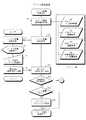
(2) Communication processing
FIGS. 20 to 41 are flowcharts showing a communication processing procedure (search for a desired work image) between the
[0120]
I. Logon process
First, logon processing is performed.
[0121]
A logon image transmission request is input by the user's device (step 51). Then, a logon request, information about the browser installed (or not installed) on the user's device (what browser is installed or not installed), and information about the user's device (For example, the number of colors that can be displayed on the display device connected to the user's device, the size of the displayable image, etc.) is transmitted from the user device to the server 1 (step 52).
[0122]
The logon image request, browser information, and device information transmitted from the user's device are received by the server 1 (step 201). Based on the browser information and device information transmitted from the user's device, image data representing an appropriate logon image that can be displayed on a display device connected to the user's device is selected from the hard disk of the server 1 (step). 202). On the hard disk of the server, a text logon image, a PC (personal computer) logon image (a personal computer logon image and a notebook computer logon image are stored as necessary), a PDA logon image, and Image data representing the log-on images for mobile phones is stored. Appropriate image data suitable for the user's device is selected in the
[0123]
In the user device, the image data representing the logon image transmitted from the
[0124]
FIG. 42 is an example of a text logon image. When a browser is not installed on the user's device, a text logon image is displayed. In the text logon image, a user name and password input instruction is displayed. The user inputs a user name and his / her password according to this instruction (step 55). The entered user name and password are transmitted from the user device to the server 1 (step 56).
[0125]
If the logon image is for a mobile phone, a little decoration such as clip art is added to the text logon image. If the logon image is for PDA, the logon image for mobile phone is further decorated. In the case of a PC logon image, the PDA logon image is further decorated. A logon image suitable for the device accessing the server (suitable for the browser) is displayed on the display device connected to the user device.
[0126]
The
[0127]
If the user name and password do not match (NO in step 206), data representing the text logon failure image stored in the hard disk of the
[0128]
Data representing a logon failure image is received at the user's device (step 57). The image data is given to a display device connected to the user's device. As a result, the logon failure image is displayed on the display device connected to the user's device (step 58).
[0129]
In the image communication system according to this embodiment, the user can set a start image displayed on a display device connected to the user's device next to the logon image. Therefore, if the user name and password match (YES in step 206), the user information (see FIG. 7) is referred to and it is checked whether the start image of the logged-on user is set by the user (step 209). ).
[0130]
If the start image has been set (YES in step 209), the process proceeds to the user start image processing shown in FIG.
[0131]
II. User start image processing
In the start image processing, with reference to the user information, start image information representing the start image of the user accessing the server 1 (information stored in the start image item of the user information in FIG. 7) is read. (Step 219). When the start image information representing the start image is read, the process proceeds to the link process shown in FIG. Based on the start image information read from the user information, it is checked which image is the start image (
[0132]
If no start image corresponds to any of the images, it is determined that an error has occurred and the process proceeds to error image processing shown in FIG.
[0133]
III. Error image processing
In the error image processing, an error image suitable for the user's device and browser is selected from the image data representing the error image recorded on the hard disk of the server 1 (step 221). An error image is generated in the
[0134]
When the data representing the error image transmitted from the
[0135]
The error image also includes a menu button. When this menu button is selected by the user (step 73), data indicating that the menu button has been selected is transmitted from the user device to the
[0136]
When data indicating that the menu button has been pressed is received by the server 1 (step 223), the process proceeds to the menu image processing shown in FIG.
[0137]
If the start image is not set by the user (NO in
[0138]
IV. Menu image processing
In the image communication system in this embodiment, as described above, the user can customize the image to be displayed on the user's display device. User information is retrieved (step 211) and it is checked whether the menu image has been customized by the user. If “none” is displayed in the user information shown in FIG. 7, it means that the user information has not been customized. If not customized, a predetermined image will be displayed.
[0139]
If the menu image has not been customized by the user (NO in step 212), data suitable for the device and browser of the user accessing the
[0140]
If the menu image is customized by the user (YES in step 212), data representing the customized menu image (user image) is output from the hard disk of the
[0141]
Even if the menu image is customized by the user, the
[0142]
When the user device receives the data representing the menu image transmitted from the server 1 (step 61), the data representing the menu image is provided to the user display device. A menu image is displayed on the user's display device as shown in FIG. 43 (step 62).
[0143]
In the menu image, items “1. Customization image”, “2. Category search image”, and “3. Keyword search image” are displayed. The user selects an image item to be displayed on the display device from these items (step 63). Data representing the selected item is transmitted from the user device to the server 1 (step 64).
[0144]
When the
[0145]
If the user selects “1. Image for customization” (YES in step 217), the customization menu processing shown in FIG. 33 is performed.
[0146]
V. Customized menu processing
Referring to FIG. 33, data representing a customized menu image suitable for the user's device and browser is read from server 1 (step 331). The read data is transmitted from the
[0147]
When the user device receives the data representing the customization menu image transmitted from the server 1 (step 101), the customization menu image is displayed on the user display device as shown in FIG. Step 102). The customization menu image displays an instruction for selecting an image to be customized by the user. The images that can be customized here are “1. Start image” (which image is the start image, that is, the image displayed next to the logon image), “2. Menu image”, “3. Customization”. There are “use image”, “4. category search image”, “5. keyword search image”, “6. work list image”, and “7. artist image”. The user selects an image to be customized from the items indicating these images (step 103). Data indicating the selected item (image) is transmitted from the user device to the server 1 (step 104).
[0148]
When data indicating the item selected by the user is received by the server 1 (step 333), it is checked whether or not it indicates the setting of the start image (step 334).
[0149]
If the item selected by the user indicates the start image setting (YES in step 334), the process proceeds to the start image setting process shown in FIG.
[0150]
VI. Start image setting process
Referring to FIG. 34, a start image setting image suitable for the user's device and browser is read from the hard disk of server 1 (step 341). Data representing the read start image setting image is transmitted from the
[0151]
When the user device receives the data representing the start image setting image transmitted from the server 1 (step 111), the data representing the start image setting image is given to the user display device. The start image setting image is displayed on the user's display device (step 112).
[0152]
FIG. 51 is an example of a start image setting image displayed on the display device of the user.
[0153]
The start image setting image displays start image selection instructions and start image items that can be selected. In this embodiment, the start images are “1 menu image”, “2. customized image”, “3. category search image”, “4. keyword search image”, “5. category search result image”, “6”. .. “work list image” and “7. artist image” can be selected, and these items are displayed in the start image setting image. Any item is selected by the user (step 113). Data representing the selected item is transmitted from the user's device to the server 1 (step 114).
[0154]
The
[0155]
When the customization menu image shown in FIG. 50 is displayed on the user's display device, if anything other than the customization of the start image is selected (NO in step 334), the process proceeds to the image editing main process shown in FIG. The main image editing process is to set whether image editing is performed by adding items or batch editing by script editing.
[0156]
VII. Main image editing process
In the main image editing process, first, the
[0157]
When the data representing the image edited image transmitted from the
[0158]
In accordance with the display of the image-edited image, the user inputs an instruction to add an item or edit a script to the user's device. If an item is to be added, which item is to be added is input (step 124). Selection data indicating addition of an item selected by the user (and an item name to be added) or script editing is transmitted from the user device to the server 1 (step 124).
[0159]
When the selection data transmitted from the user device is received in the server 1 (step 353), it is determined whether the page editing is completed (step 354), script editing (step 355), or item addition.
[0160]
If the image editing ends (it is omitted in FIG. 52 but the user can also specify completion of image editing) (YES in step 354), the process proceeds to the customization menu image processing shown in FIG.
[0161]
If it is script editing (YES in step 355), the process proceeds to script editing processing shown in FIG.
[0162]
VIII. Script editing process
Referring to FIG. 36, in the case of script editing processing, data representing a script editing image suitable for the user device and browser is read from the hard disk of the server (step 361). Also, a script for the edited image that the user wants to customize is initialized (step 362). The read data is transmitted from the
[0163]
When the data representing the script edit image transmitted from the server is received at the user device (step 131), the data representing the script edit image is given to the user display device. A script-edited image as shown in FIG. 53 is displayed on the user device (step 132).
[0164]
In the script editing image, the text “Perform batch editing by script. Please enter the script.” Is displayed. When a script is input by the user (step 133), the input script is displayed on the script editing image. Data indicating the script input by the user is transmitted from the user's device to the server 1 (step 134).
[0165]
When the
[0166]
If it is a script editing stop request (YES in step 365), the process returns to the image editing main process shown in FIG.
[0167]
If it is not a script editing stop request (NO in step 365), it is checked whether or not there is an error in the data representing the transmitted script (
[0168]
If there is an error (YES in step 367), the error message is set as a script error and the content is written as a script (step 368). The script transmitted from the user is set to be transmitted to the user (step 369). The script sent from the user is returned to the user.
[0169]
If a script error does not occur (NO in step 367), it is determined whether the file representing the edited image defined by the edited script is a new file that is not stored on the hard disk of the
[0170]
If there is no new file (NO in step 370), the process proceeds to the customization content reflection process shown in FIG.
[0171]
IX. Customized content reflection processing
Data representing the image selected by the user is updated according to the script transmitted from the user. The updated data is stored in the hard disk of the server 1 (step 392). Also, the user information about the customized image is updated (step 393). Thereafter, the process proceeds to the customization process shown in FIG.
[0172]
If there is a new file (YES in step 370), the process proceeds to the new file transmission process shown in FIG.
[0173]
X. New file transmission processing
In the server, data representing a file transmission image suitable for the user's device and browser is read (step 381). The error message is initialized and the send file list is set to all new files (set to send all new files to the server) (step 382). Data representing a file transmission image, an error message, and a transmission file list are transmitted from the
[0174]
When data representing a file transmission image, an error message, and a transmission file list are received at the user's device (step 141), the received data is transmitted to the user's display device (step 142). As shown in FIG. 54, a file transmission image is displayed on the user's device (step 142). The file name indicating the new image file is input by the user (step 143). The input file name is displayed on the file transmission image. The file specified by the input file name is read from the user device and transmitted to the server 1 (step 144).
[0175]
In the
[0176]
If there is a script editing stop request (YES in step 385), the process proceeds to the image editing main process shown in FIG.
[0177]
If there is no script editing stop request (NO in step 385), it is checked whether or not there is an error in the transmitted file (
[0178]
If an error is included (YES in step 387), an error message is written as a file transfer error (step 388), the send file list is made into an error file, and the new file in error is sent again. (Step 389). Thereafter, the processing from
[0179]
If no error is included (NO in step 387), the process proceeds to the customization content reflection process shown in FIG.
[0180]
In the customization content reflection process, the new file received by the
[0181]
Returning to FIG. 21, if the user has set a category search image in the menu image (YES in step 218), the process proceeds to the category search image processing shown in FIG.
[0182]
XI. Category search image processing
First, it is confirmed by referring to the user information whether or not data representing a unique category search image (user image) customized by the user is stored in the hard disk of the server 1 (step 251). If there is data representing a category search image unique to the user (YES in step 252), data representing the category search image unique to the user is read from the hard disk (step 253). If data representing a category search image unique to the user is not stored in the server 1 (NO in step 252), data representing a category search image suitable for the user's device and browser is read from the hard disk of the server 1 (step 255). ). Data representing the read category search image is transmitted from the
[0183]
When the user device receives the data representing the category search image transmitted from the server 1 (step 81), the received data is given to the user display device (step 82). The category search image shown in FIG. 45 is displayed on the display device of the user. The category to be searched is displayed in the category search image. In the example shown in FIG. 45, there are “1. By artist”, “2. By theme”, “3. By age”, “4. By country”, and “5. By data format”. One of the categories is selected by the user (step 83). Data representing the selected category is transmitted from the user device to the server 1 (step 84).
[0184]
Based on the data representing the category received by the server 1 (step 256), a work image search process is executed (step 257). Thereafter, the process proceeds to the category search result process shown in FIG.
[0185]
XII. Category search result processing
Referring to FIG. 27, the category search result image customized by the user is searched in the user information (step 261). If the user has customized the category search result image, since there is a user customized image (user image), the category search result image for the user is searched from the hard disk of the server 1 (step 263). If the user has not customized the category search result image, a search result image suitable for the user's device and browser is read from the hard disk of the
[0186]
VIII. Edit image creation process
Referring to FIG. 31, an additional program suitable for the edited image to be created is read from the hard disk of server 1 (step 301). In this case, an additional program suitable for creating the search result image (for example, a program for executing processing defined by the user in the script) is read from the hard disk of the
[0187]
The user's device receives the edited image data representing the search result transmitted from the server 1 (step 91). When the edited image data representing the search result is given to the user's display device, the edited image showing the search result is displayed on the user's display device (step 92). The link destination (image, text, URL name, etc.) displayed in the search result image is designated by the user (step 93). Data indicating the designated link destination is transmitted from the user device to the server 1 (step 94).
[0188]
The
[0189]
Returning to FIG. 21, when the user selects “3. Keyword search image” in the menu image (see FIG. 43) displayed on the display device of the user, the process proceeds to the keyword search image processing shown in FIG. NO at 28).
[0190]
XIV. Keyword search image processing
Referring to FIG. 24, a keyword search image customized by the user is searched based on the user information (step 231). If there is a keyword search image (user image) customized by the user (YES in step 232), data representing the image is read from the hard disk of the server 1 (step 233). If there is no keyword search image customized by the user (NO in step 232), a default keyword search image is read from the hard disk of the server 1 (step 235). In any case, data representing the keyword search image read from the hard disk of the
[0191]
In the user device, data representing the keyword search image transmitted from the
[0192]
In the keyword search image, an instruction “Please enter a keyword” is displayed. In accordance with this instruction, the user inputs a keyword (step 77). The input keyword is displayed on the display device of the user. The input keyword is transmitted from the user device to the server 1 (step 78).
[0193]
The
[0194]
XV. Search result image processing
In FIG. 25, whether there is a search result image customized by the user is searched in the user information (step 241). If there is a search result image customized by the user by the search (YES in step 242), data representing the search result image is read from the hard disk of the server 1 (step 243). If there is no search result image customized by the user (NO in step 242), data representing a predetermined search result image suitable for the user's device and browser is read from the hard disk of the server (step 244). Thereafter, the process proceeds to an edited image creation process shown in FIG. 31, and a keyword search result image is created and transmitted to the user's device in the same manner as the category search image creation process described above.
[0195]
The keyword search result image is displayed on the display device of the user.
[0196]
In the link process (see FIG. 32), when the work list image is displayed on the user's display device (YES in step 318), the process proceeds to the work list process shown in FIG.
[0197]
XVI. Work list processing
Referring to FIG. 28, a work list image customized by the user is searched in the user information (step 271). If there is a work list image (user image) customized by the user in server 1 (YES in step 272), data representing the work list image is read from the hard disk of server 1 (step 273). If there is no work list image customized by the user in server 1 (NO in step 272), data representing a work list image suitable for the user's device among the predetermined work list images stored in the hard disk of
[0198]
46 to 49 are examples of work list images.
[0199]
FIG. 44 is a work list image displayed when the user's device is a mobile phone (or a device that can display only text). In mobile phones, it is relatively difficult to display images. For this reason, a work list image suitable for a display device of a mobile phone is displayed.
[0200]
FIG. 46 is a work list image displayed when the user's device is a mobile terminal. A mobile terminal can display an image, but the display screen of the display device is not so large. For this reason, the work list image which is not so large is displayed on the display device of the portable terminal.
[0201]
FIG. 47 shows a work list image displayed when a user's device personal computer is connected to a small display device. A relatively large work list image is displayed.
[0202]
FIG. 49 is a work list image that is displayed when a user's device personal computer is connected to a display device having a large display screen. A work list image suitable for being displayed on a large display screen is displayed.
[0203]
The work list image shown in FIG. 47 uses a small image, the work list image shown in FIG. 48 uses a medium-sized image, and the work list image shown in FIG. 49 has a large image. Is used. In this way, data representing a work list image composed of images of different sizes depending on the user's device is transmitted from the
[0204]
XVII. Artist image processing
FIG. 29 shows artist image processing.
[0205]
When linking to the artist image, the artist image customized by the user is searched on the hard disk of the server 1 (step 281). If there is an artist image customized by the user (YES in step 282), data representing the customized image is read from the hard disk of the server 1 (step 283). If there is no artist image customized by the user (NO in step 282), data representing the artist image suitable for the user's device and browser is read from the hard disk of the server 1 (step 284). Data representing an artist image is created from the data read in the edited image creation process shown in FIG. Data representing the created artist image is transmitted to the user's device, and an artist image suitable for the user's device and browser or an artist image customized by the user is displayed on the user's display device.
[0206]
XVIII. Work image processing
FIG. 30 shows the work image processing.
[0207]
When linking to a work image, the work image customized by the user is searched on the hard disk of the server 1 (step 291). If there is a work image (user image) customized by the user (YES in step 292), data representing the customized work image is read from the hard disk of the server 1 (step 293). If there is no work image customized by the user (NO in step 292), a work image suitable for the user's device and browser is read from the hard disk of the server 1 (step 294). In any case, data representing a work image is generated based on the process for the work image read from the hard disk of the
[0208]
When displaying work images, artist images, etc., as described above, each file group is searched as shown in FIGS. 8A to 10A and 10B, and the corresponding file is used. Needless to say.
[0209]
Returning to FIG. 35, if the script is not edited, the image is customized by adding an image item (NO in step 355).
[0210]
First, the script is initialized (step 356). Thereafter, the process proceeds to image item addition processing (step 357). The image item addition process will be described next. When the image item addition processing is completed, it is checked whether or not a new file has been added in the image item addition processing (step 358). If a new file has been added (YES in step 358), the process proceeds to a new file addition process shown in FIG. If no new file has been added (NO in step 358), the process proceeds to the customization content reflection process shown in FIG. In any case, as described above, the user information is updated when the display item is added by customization.
[0211]
XIX. Image item addition processing
FIG. 38 is a flowchart showing image item addition processing.
[0212]
Data representing an additional item selection image suitable for the user's device and browser is read from the hard disk of the server 1 (step 401). Data representing the read additional item selection image is transmitted from the
[0213]
Data representing an additional item selection image is received at the user's device (step 151) and provided to the user's display device (step 152). An additional item selection image as shown in FIG. 55 is displayed on the user's display device (step 152).
[0214]
In the additional item selection image, the text of the question “Do you want to add a layout or place a file?” Is displayed. The user selects a desired process from “add layout” or “file placement” according to the text (step 153). Data representing the selected content is transmitted from the user's device to the server 1 (step 154).
[0215]
The
[0216]
XX. Layout addition processing
The layout addition process will be described with reference to FIG.
[0217]
Data representing a layout selection image suitable for the user's device and browser is read from the hard disk of the server 1 (step 411). The read data is transmitted from the
[0218]
In the user device, data representing the layout selection image transmitted from the
[0219]
The
[0220]
XXI. File placement processing
FIG. 41 is a flowchart showing the file arrangement process.
[0221]
Data representing a file layout image suitable for the user's device and browser is read from the hard disk of the server 1 (step 421). The read data is transmitted from the
[0222]
In the user device, data representing the file arrangement image transmitted from the
[0223]
The file layout image includes the following areas.
[0224]
In this arrangement file area, an
[0225]
This is for designating a target (for example, an image, an author name, a title, etc.) to be displayed among files (management files) selected in the
[0226]
The
[0227]
Link setting area 511;
This is an area for setting the link destination.
[0228]
This is to specify a search target to be hit by the search. For example, when only works of a certain age or more are to be searched, the age is input by the user.
[0229]
Display areas 513 and 514;
Specifies the area for displaying images, text, and buttons. The horizontal size is input to the area 513, and the vertical size is input to the area 514.
[0230]
This is an area for inputting a color number for specifying a color to be displayed.
[0231]
Color
This area specifies the number of colors to be displayed. For example, 256 colors and 16 million colors are input.
[0232]
Font designation area 517;
This area specifies the font to be displayed. For example, Gothic and Mincho are entered.
[0233]
This area is used to specify the character size.
[0234]
Emphasis designation input 519;
Input when emphasizing characters. For example, underline, character inversion, and hollow character are input.
[0235]
In addition, the file placement image includes an
[0236]
The user performs a predetermined selection process using the file selection image (step 173). Data indicating the selected contents is transmitted from the user device to the server 1 (step 174).
[0237]
In the
[0238]
The user can customize the image displayed on the display device of the user relatively freely. In addition, when not customized, an image suitable for the user's device and browser is displayed on the user's display device.
[Brief description of the drawings]
FIG. 1 shows an overview of an image communication system.
FIG. 2 is a block diagram showing an electrical configuration of a server.
FIG. 3 shows software and the like stored in the server.
FIG. 4 is a block diagram showing an electrical configuration of a personal computer.
FIG. 5 shows software and the like stored in a personal computer.
FIG. 6 shows image transition.
FIG. 7 shows user information.
8A shows an artist image management file, and FIGS. 8B to 8D show artist image files. FIG.
FIG. 9A shows a work image management file, and FIGS. 9B and 9C show work image files.
10A shows a text management file, and FIG. 10B shows a text file.
FIG. 11 shows image transition.
FIG. 12 shows an example of a script.
FIG. 13 shows an example of a script.
FIG. 14 shows an example of a script.
FIG. 15 shows an example of a script.
FIG. 16 shows an example of a script.
FIG. 17 shows an example of a script.
FIG. 18 shows an example of a script.
FIG. 19 shows an example of a script.
FIG. 20 is a flowchart showing logon processing.
FIG. 21 is a flowchart showing menu image processing.
FIG. 22 is a flowchart showing user start image processing;
FIG. 23 is a flowchart showing error image processing.
FIG. 24 is a flowchart showing a keyword search process.
FIG. 25 is a flowchart showing search result image processing;
FIG. 26 is a flowchart showing category search image processing;
FIG. 27 is a flowchart showing category search result processing;
FIG. 28 is a flowchart showing a work list process;
FIG. 29 is a flowchart showing artist image processing;
FIG. 30 is a flowchart showing work image processing;
FIG. 31 is a flowchart showing edited image processing;
FIG. 32 is a flowchart showing link processing.
FIG. 33 is a flowchart showing customization menu processing;
FIG. 34 is a flowchart showing a start image setting process.
FIG. 35 is a flowchart showing image editing main processing.
FIG. 36 is a flowchart showing script batch editing processing;
FIG. 37 is a flowchart showing a new file transmission process.
FIG. 38 is a flowchart showing customization content reflection processing;
FIG. 39 is a flowchart showing image item addition processing;
FIG. 40 is a flowchart showing a layout addition process.
FIG. 41 is a flowchart showing a file arrangement process.
FIG. 42 shows a logon image.
FIG. 43 shows a menu image.
FIG. 44 shows a keyword search image.
FIG. 45 shows a category search image.
FIG. 46 shows a work list image.
FIG. 47 shows a work list image.
FIG. 48 shows a work list image.
FIG. 49 shows a work list image.
FIG. 50 shows a customization menu image.
FIG. 51 shows a start image setting image.
FIG. 52 shows an image editing image.
FIG. 53 shows a script edit image.
FIG. 54 shows a file transmission image.
FIG. 55 shows an additional item selection image.
FIG. 56 shows a layout selection image.
FIG. 57 shows a file arrangement image.
[Explanation of symbols]
1 server
4 Network card
6 CD-ROM drive
8 Keyboard
10 CPU
23 Display device
30 Personal computer
31 notebook computers
32 Personal digital assistant
33 Mobile phone
44 Modem
Claims (13)
Translated fromJapanese上記画像受信装置が,
上記画像送信装置に,上記画像受信装置に表示可能な画像の大きさの情報を送信する装置情報送信手段を備え,
上記画像送信装置が,
上記画像受信装置の上記装置情報送信手段から送信された上記画像受信装置に表示可能な画像の大きさの情報を受信する装置情報受信手段,および
上記装置情報受信手段によって受信した画像受信装置に表示可能な画像の大きさの情報にもとづいて,上記画像受信装置に表示可能な大きさをもつ画像を表す画像データを上記画像受信装置に送信する画像データ送信手段,
を備えた画像通信システム。In an image communication system composed of an image transmission device and an image reception device capable of data communication with each other,
The image receiving device is
The image transmitting device includes device information transmitting means for transmitting information aboutthe size of an image that can be displayed on the image receiving device,
The image transmission device is
The device information device information receiving means for receiving informationof the size of the displayable image on the image receiving apparatus transmitted from the transmitting unit of the image receiving apparatus, and adisplay on the image receiving apparatus received by the apparatus information receiving meanspossible image based on thesize of the information, the image data transmitting means for transmitting the image data representing an image having atableviewable sizeto the image receiving apparatus to the image reception apparatus,
An image communication system.
上記画像データ送信手段が,上記装置情報受信手段によって受信した画像受信装置に表示可能な画像の大きさの情報にもとづいて,上記記憶手段の中から上記画像受信装置に表示可能な大きさをもつ画像を表す画像データを上記画像受信装置に送信するものである,
請求項1に記載の画像通信システム。The image transmission device further includes storage means for storing image datarepresenting a plurality of differentsizes ,
The image data transmission means, based on thesize of the informationof the displayable image on the image receiving apparatus received by the apparatus information receiving means, thetableviewable sizeto the image receiving apparatus from among the storage means Transmitting image data representing an image to the image receiving device,
The image communication system according to claim 1.
請求項1に記載の画像通信システム。The image data transmitting means of the image transmitting device transmits edited image data representing an edited image composed of a plurality of display items such as images and sentences to the image receiving device.
The image communication system according to claim 1.
上記編集画像のレイアウトおよび上記表示項目の少なくとも一方を設定する設定手段,ならびに
上記設定手段により設定された情報を上記画像送信装置に送信する設定情報送信手段をさらに備え,
上記画像送信装置が,
上記画像受信装置の上記設定情報送信手段から送信された設定情報を受信する設定情報受信手段,ならびに
上記編集画像データによって表される編集画像のレイアウトおよび表示項目の少なくとも一方を,上記設定情報受信手段によって受信された設定情報にもとづいて決定する決定手段,
をさらに備えた請求項3に記載の画像通信システム。The image receiving device is
Setting means for setting at least one of the layout of the edited image and the display item, and setting information transmitting means for transmitting information set by the setting means to the image transmitting device,
The image transmission device is
Setting information receiving means for receiving setting information transmitted from the setting information transmitting means of the image receiving device, and at least one of the layout and display items of the edited image represented by the edited image data, the setting information receiving means Determining means for determining on the basis of the setting information received by
The image communication system according to claim3 , further comprising:
上記編集画像の全体を一括して編集するように設定する,あるいは上記編集画像の一部を編集するように設定するものである,
請求項4に記載の画像通信システム。The setting means of the image receiving device is
Set to edit the entire edited image at once, or set to edit a part of the edited image.
The image communication system according to claim4 .
上記複数画像データ記憶手段に記憶されている画像データのうちいずれか1つの画像データによって表わされる画像を用いて上記編集画像を生成する生成手段をさらに備えた,
請求項3に記載の画像通信システム。Any one of the image data representing the image constituting the edited image is stored, and the image data is stored in the plurality of image data storage means. A generating means for generating the edited image using an image represented by the data;
The image communication system according to claim3 .
上記画像受信装置は,レイアウトおよび上記表示項目の少なくとも一方が上記設定手段により設定されるべき上記編集画像を指定する編集画像指定手段をさらに備え,
上記設定手段は,上記編集画像指定手段により指定された編集画像について上記レイアウトおよび上記表示項目の少なくとも一方を設定するものである,
請求項4に記載の画像通信システム。Image data representing an image of a plurality of frames is transmitted from the image transmitting device to the image receiving device;
The image receiving device further includes an edited image designating unit for designating the edited image in which at least one of a layout and the display item is to be set by the setting unit,
The setting means sets at least one of the layout and the display item for the edited image specified by the edited image specifying means.
The image communication system according to claim4 .
上記画像受信装置が,上記画像送信装置の上記画像候補送信手段から送信されたデータによって表わされる画像の候補の中から,上記画像受信装置と上記画像送信装置とが正式に接続されたときに最初に表示される画像を選択する選択手段,および
上記選択手段によって選択された画像を表すデータを上記画像送信装置に送信する選択画像送信手段をさらに備え,
上記画像送信装置が,
上記画像受信装置の上記選択画像送信手段から送信された選択画像データを受信する選択画像受信手段をさらに備え,
上記画像データ送信手段が,
上記装置情報受信手段によって受信した画像受信装置に表示可能な画像の大きさの情報にもとづいて決定される大きさをもつものであって,かつ上記選択画像受信手段によって受信された選択画像データによって表される画像を表す画像データを,上記画像受信装置と上記画像送信装置とが正式に接続されたときに上記画像受信装置に送信するものである,
請求項1に記載の画像通信システム。The image transmission device further includes image candidate transmission means for transmitting data representing image candidates to be displayed first to the image reception device when the image reception device and the image transmission device are officially connected to each other. When the image receiving apparatus is officially connected to the image receiving apparatusfrom among the image candidates represented by the data transmitted from the image candidate transmitting means of the image transmitting apparatus, Selection means for selecting an image displayed on the screen, and selection image transmission means for transmitting data representing the image selected by the selection means to the image transmission device,
The image transmission device is
A selection image receiving means for receiving the selected image data transmitted from the selected image transmission means of the image receiving device;
The image data transmission means is
According to the selected image datahaving a size determined based on the size information of the image that can be displayed on the image receiving device received by the device information receiving means, and received by the selected image receiving means Image data representing an image to be represented is transmitted to the image receiving device when the image receiving device and the image transmitting device are formally connected;
The image communication system according to claim 1.
画像更新指令を上記画像送信手段に送信する更新指令送信手段をさらに備え,
上記画像送信装置が,
上記更新指令送信手段から送信された上記画像の更新指令を受信する更新指令受信手段をさらに備え,
上記画像データ送信手段が,
上記更新指令受信手段によって受信した更新指令および上記画像受信装置に関する情報に応じた画像データであって,上記画像データ送信手段によって上記画像受信手段に送信された画像データにより表される画像にリンクされている次の画像を表す画像データを上記画像受信装置に送信するものである,
請求項1に記載の画像通信システム。The image receiving device is
Update command transmission means for transmitting an image update command to the image transmission means;
The image transmission device is
Update command receiving means for receiving an update command for the image transmitted from the update command transmitting means;
The image data transmission means is
Image data corresponding to the update command received by the update command receiving means and information relating to the image receiving device, and linked to an image represented by the image data transmitted to the image receiving means by the image data transmitting means. Transmitting image data representing the next image to the image receiving device,
The image communication system according to claim 1.
上記リンクすべき画像を設定するリンク画像設定手段,および
上記リンク画像設定手段によって設定されたリンク情報を,上記画像送信装置に送信するリンク情報送信手段をさらに備え,
上記画像送信装置が,
上記画像受信装置の上記リンク情報送信手段から送信されたリンク情報を受信するリンク情報受信手段をさらに備え,
上記画像データ送信手段が,上記リンク情報受信手段によって受信したリンク情報にもとづいて上記リンクされる次の画像を表わす画像データを上記受信装置に送信するものである,
請求項8に記載の画像通信システム。The image receiving device is
Link image setting means for setting the image to be linked, and link information transmitting means for transmitting the link information set by the link image setting means to the image transmitting device,
The image transmission device is
Link information receiving means for receiving link information transmitted from the link information transmitting means of the image receiving device;
The image data transmitting means transmits image data representing the next image to be linked to the receiving device based on the link information received by the link information receiving means;
The image communication system according to claim8 .
上記画像受信装置から送信された画像受信装置に表示可能な画像の大きさの情報を受信する装置情報受信手段,および
上記装置情報受信手段によって受信した画像受信装置に表示可能な画像の大きさの情報にもとづいて,上記画像受信装置に表示可能な大きさをもつ画像を表す画像データを上記画像受信装置に送信する画像データ送信手段,
を備えた画像送信装置。In an image transmission device capable of data communication with an image reception device,
The image receiving apparatuscapable of displaying images on the image receiving apparatus transmitted fromthe magnitude apparatus information receiving means for receiving information, and the device informationof the displayable image on the image receiving apparatus received by the receiving meansthe size of the based on the information, the image data transmitting means for transmitting the image data representing an image having atableviewable sizeto the image receiving apparatus to the image reception apparatus,
An image transmission apparatus comprising:
上記画像受信装置から送信された画像受信装置に表示可能な画像の大きさの情報を受信し,
受信した画像受信装置に表示可能な画像の大きさの情報にもとづいて,上記画像受信装置に表示可能な大きさをもつ画像を表す画像データを上記画像受信装置に送信する,
画像データ送信方法。In an image transmission device capable of data communication with an image reception device,
Receiving information onthe size of an image that can be displayed on the image receiving device transmitted from the image receiving device;
Based onthe size of the informationof the displayable image on the received image receiving device, transmits the image data representing an image havingatable viewablesizeto the image receiving apparatus to the image reception apparatus,
Image data transmission method.
上記画像受信装置から送信された画像受信装置に表示可能な画像の大きさの情報を受信させ,
受信した画像受信装置に表示可能な画像の大きさの情報にもとづいて,上記画像受信装置に表示可能な大きさをもつ画像を表す画像データを上記画像受信装置に送信させるように上記画像送信装置のコンピュータを制御するためのプログラムを格納したコンピュータが読み取り可能な記録媒体。A program for controlling a computer of an image transmission device capable of data communication with an image reception device,
Receivingimage size information thatcan be displayed on the image receiving device transmitted from the image receiving device;
Based onthe size of the informationof the displayable image on the received image receiving apparatus, the image transmission so as to transmit the image data representing an image havingatable viewablesizeto the image receiving apparatus to the image reception apparatus A computer-readable recording medium storing a program for controlling the computer of the apparatus.
Priority Applications (2)
| Application Number | Priority Date | Filing Date | Title |
|---|---|---|---|
| JP20159199AJP4094777B2 (en) | 1999-07-15 | 1999-07-15 | Image communication system |
| US09/616,673US6750830B1 (en) | 1999-07-15 | 2000-07-14 | Image communication system |
Applications Claiming Priority (1)
| Application Number | Priority Date | Filing Date | Title |
|---|---|---|---|
| JP20159199AJP4094777B2 (en) | 1999-07-15 | 1999-07-15 | Image communication system |
Publications (2)
| Publication Number | Publication Date |
|---|---|
| JP2001034249A JP2001034249A (en) | 2001-02-09 |
| JP4094777B2true JP4094777B2 (en) | 2008-06-04 |
Family
ID=16443607
Family Applications (1)
| Application Number | Title | Priority Date | Filing Date |
|---|---|---|---|
| JP20159199AExpired - Fee RelatedJP4094777B2 (en) | 1999-07-15 | 1999-07-15 | Image communication system |
Country Status (2)
| Country | Link |
|---|---|
| US (1) | US6750830B1 (en) |
| JP (1) | JP4094777B2 (en) |
Families Citing this family (19)
| Publication number | Priority date | Publication date | Assignee | Title |
|---|---|---|---|---|
| JP2001331362A (en)* | 2000-03-17 | 2001-11-30 | Sony Corp | File conversion method, data converter and file display system |
| JP4551546B2 (en)* | 2000-09-28 | 2010-09-29 | キヤノン株式会社 | Server device of network system and control method thereof |
| JP2002202389A (en)* | 2000-10-31 | 2002-07-19 | Sony Corp | Clock information distribution processing system, information distribution device, information distribution system, portable terminal device, information recording medium and information processing method |
| US20020103935A1 (en)* | 2001-01-26 | 2002-08-01 | Neil Fishman | Pushing rich content information to mobile devices |
| JP2003150145A (en) | 2001-11-09 | 2003-05-23 | Nec Corp | Image display method and portable information equipment |
| US7287162B2 (en)* | 2001-12-13 | 2007-10-23 | Sierra Wireless, Inc. | System and method for platform activation |
| JP4005961B2 (en)* | 2003-09-05 | 2007-11-14 | 松下電器産業株式会社 | Media receiver |
| US7511682B2 (en) | 2004-05-03 | 2009-03-31 | Microsoft Corporation | Context-aware auxiliary display platform and applications |
| US7660914B2 (en) | 2004-05-03 | 2010-02-09 | Microsoft Corporation | Auxiliary display system architecture |
| US7558884B2 (en)* | 2004-05-03 | 2009-07-07 | Microsoft Corporation | Processing information received at an auxiliary computing device |
| US7577771B2 (en)* | 2004-05-03 | 2009-08-18 | Microsoft Corporation | Caching data for offline display and navigation of auxiliary information |
| EP1655931A1 (en)* | 2004-11-04 | 2006-05-10 | Swisscom Mobile AG | Method for replay of image data |
| US7796837B2 (en)* | 2005-09-22 | 2010-09-14 | Google Inc. | Processing an image map for display on computing device |
| JP5168771B2 (en)* | 2005-10-28 | 2013-03-27 | カシオ計算機株式会社 | Screen generation apparatus and program |
| KR101405923B1 (en)* | 2007-02-20 | 2014-06-12 | 엘지전자 주식회사 | A method of setting a screen of a terminal and a terminal |
| WO2011114185A1 (en)* | 2010-03-15 | 2011-09-22 | Comviva Technologies Limited | Method and system for implementation of user interface for video call based services |
| JP5898834B2 (en) | 2010-05-24 | 2016-04-06 | ヤマハ株式会社 | Information processing system |
| US9679606B2 (en)* | 2011-09-14 | 2017-06-13 | Cable Television Laboratories, Inc. | Method of modifying play of an original content form |
| JP5655896B2 (en)* | 2013-06-10 | 2015-01-21 | 株式会社リコー | Network system, image forming apparatus, program, and image data transmission / reception method |
Family Cites Families (7)
| Publication number | Priority date | Publication date | Assignee | Title |
|---|---|---|---|---|
| US6400996B1 (en)* | 1999-02-01 | 2002-06-04 | Steven M. Hoffberg | Adaptive pattern recognition based control system and method |
| US5293484A (en)* | 1992-07-22 | 1994-03-08 | Signtel, Inc. | Method and apparatus for controlling electronics signs using radiopaging signals |
| JPH06188937A (en)* | 1992-12-16 | 1994-07-08 | Canon Inc | Data processing device |
| US5513126A (en)* | 1993-10-04 | 1996-04-30 | Xerox Corporation | Network having selectively accessible recipient prioritized communication channel profiles |
| US6049316A (en)* | 1997-06-12 | 2000-04-11 | Neomagic Corp. | PC with multiple video-display refresh-rate configurations using active and default registers |
| US6253326B1 (en)* | 1998-05-29 | 2001-06-26 | Palm, Inc. | Method and system for secure communications |
| US6199099B1 (en)* | 1999-03-05 | 2001-03-06 | Ac Properties B.V. | System, method and article of manufacture for a mobile communication network utilizing a distributed communication network |
- 1999
- 1999-07-15JPJP20159199Apatent/JP4094777B2/ennot_activeExpired - Fee Related
- 2000
- 2000-07-14USUS09/616,673patent/US6750830B1/ennot_activeExpired - Lifetime
Also Published As
| Publication number | Publication date |
|---|---|
| US6750830B1 (en) | 2004-06-15 |
| JP2001034249A (en) | 2001-02-09 |
Similar Documents
| Publication | Publication Date | Title |
|---|---|---|
| JP4094777B2 (en) | Image communication system | |
| US20120079015A1 (en) | Internet-based computer for mobile and thin client users | |
| US20030046345A1 (en) | System and method for project management | |
| US20030034991A1 (en) | Method of constructing a composite image | |
| JP2002189595A (en) | Integrated method for creating refreshable web query | |
| JP2000222324A (en) | Web page customization system | |
| JPH07219736A (en) | Creation method of multimedia application business | |
| JP2002063013A (en) | Method and system for capturing graphical printing techniques in a web browser | |
| WO2004097656A1 (en) | Content creation system, content creation method, computer-executable program for executing the content creation method, computer-readable recording medium containing the program, graphical user interface system, and display control method | |
| JP2007328510A (en) | Content conversion device, content display device, content browsing device, content conversion method, content browsing method, and program | |
| US20080010586A1 (en) | Enhanced handling of repeated information in a web form | |
| JP2001084212A (en) | Method for preparing homepage | |
| JP3963614B2 (en) | Data communication system and server and client computer constituting data communication system | |
| AU2024219940A1 (en) | Systems and methods for automatically generating designs | |
| JP2004038283A (en) | Contents management program, information processor, and information processing method | |
| KR100496981B1 (en) | A PDF Document Providing Method Using XML | |
| JP2006185064A (en) | Data processing apparatus and program | |
| JP2003099424A (en) | Document data structure, storage medium, and information processing device | |
| JP2000222326A (en) | Learning support method and system, and storage medium storing learning support program | |
| JP5237875B2 (en) | Shared article publishing system | |
| CN111027280A (en) | Method and system for generation and rendering of digital publications, and readable storage medium | |
| Ruvalcaba | Adobe Dreamweaver CS4 Unleashed | |
| JP2003099263A (en) | Document data structure, storage medium, information processing apparatus and information processing system | |
| Ruvalcaba | Macromedia Dreamweaver 8 Unleashed | |
| JP2000137640A (en) | Hypertext automatic creation device and computer-readable recording medium recording automatic hypertext creation processing program |
Legal Events
| Date | Code | Title | Description |
|---|---|---|---|
| A621 | Written request for application examination | Free format text:JAPANESE INTERMEDIATE CODE: A621 Effective date:20040917 | |
| A711 | Notification of change in applicant | Free format text:JAPANESE INTERMEDIATE CODE: A712 Effective date:20061206 | |
| A131 | Notification of reasons for refusal | Free format text:JAPANESE INTERMEDIATE CODE: A131 Effective date:20071218 | |
| A521 | Request for written amendment filed | Free format text:JAPANESE INTERMEDIATE CODE: A523 Effective date:20080130 | |
| TRDD | Decision of grant or rejection written | ||
| A01 | Written decision to grant a patent or to grant a registration (utility model) | Free format text:JAPANESE INTERMEDIATE CODE: A01 Effective date:20080226 | |
| A61 | First payment of annual fees (during grant procedure) | Free format text:JAPANESE INTERMEDIATE CODE: A61 Effective date:20080306 | |
| FPAY | Renewal fee payment (event date is renewal date of database) | Free format text:PAYMENT UNTIL: 20110314 Year of fee payment:3 | |
| R150 | Certificate of patent or registration of utility model | Ref document number:4094777 Country of ref document:JP Free format text:JAPANESE INTERMEDIATE CODE: R150 Free format text:JAPANESE INTERMEDIATE CODE: R150 | |
| FPAY | Renewal fee payment (event date is renewal date of database) | Free format text:PAYMENT UNTIL: 20110314 Year of fee payment:3 | |
| FPAY | Renewal fee payment (event date is renewal date of database) | Free format text:PAYMENT UNTIL: 20120314 Year of fee payment:4 | |
| R250 | Receipt of annual fees | Free format text:JAPANESE INTERMEDIATE CODE: R250 | |
| FPAY | Renewal fee payment (event date is renewal date of database) | Free format text:PAYMENT UNTIL: 20120314 Year of fee payment:4 | |
| FPAY | Renewal fee payment (event date is renewal date of database) | Free format text:PAYMENT UNTIL: 20130314 Year of fee payment:5 | |
| R250 | Receipt of annual fees | Free format text:JAPANESE INTERMEDIATE CODE: R250 | |
| FPAY | Renewal fee payment (event date is renewal date of database) | Free format text:PAYMENT UNTIL: 20130314 Year of fee payment:5 | |
| FPAY | Renewal fee payment (event date is renewal date of database) | Free format text:PAYMENT UNTIL: 20140314 Year of fee payment:6 | |
| R250 | Receipt of annual fees | Free format text:JAPANESE INTERMEDIATE CODE: R250 | |
| R250 | Receipt of annual fees | Free format text:JAPANESE INTERMEDIATE CODE: R250 | |
| R250 | Receipt of annual fees | Free format text:JAPANESE INTERMEDIATE CODE: R250 | |
| R250 | Receipt of annual fees | Free format text:JAPANESE INTERMEDIATE CODE: R250 | |
| R250 | Receipt of annual fees | Free format text:JAPANESE INTERMEDIATE CODE: R250 | |
| R250 | Receipt of annual fees | Free format text:JAPANESE INTERMEDIATE CODE: R250 | |
| LAPS | Cancellation because of no payment of annual fees |