JP4094185B2 - Cold power generation system - Google Patents
Cold power generation systemDownload PDFInfo
- Publication number
- JP4094185B2 JP4094185B2JP26526499AJP26526499AJP4094185B2JP 4094185 B2JP4094185 B2JP 4094185B2JP 26526499 AJP26526499 AJP 26526499AJP 26526499 AJP26526499 AJP 26526499AJP 4094185 B2JP4094185 B2JP 4094185B2
- Authority
- JP
- Japan
- Prior art keywords
- carbon dioxide
- gas turbine
- gas
- combustor
- lng
- Prior art date
- Legal status (The legal status is an assumption and is not a legal conclusion. Google has not performed a legal analysis and makes no representation as to the accuracy of the status listed.)
- Expired - Fee Related
Links
Images
Classifications
- Y—GENERAL TAGGING OF NEW TECHNOLOGICAL DEVELOPMENTS; GENERAL TAGGING OF CROSS-SECTIONAL TECHNOLOGIES SPANNING OVER SEVERAL SECTIONS OF THE IPC; TECHNICAL SUBJECTS COVERED BY FORMER USPC CROSS-REFERENCE ART COLLECTIONS [XRACs] AND DIGESTS
- Y02—TECHNOLOGIES OR APPLICATIONS FOR MITIGATION OR ADAPTATION AGAINST CLIMATE CHANGE
- Y02E—REDUCTION OF GREENHOUSE GAS [GHG] EMISSIONS, RELATED TO ENERGY GENERATION, TRANSMISSION OR DISTRIBUTION
- Y02E20/00—Combustion technologies with mitigation potential
- Y02E20/16—Combined cycle power plant [CCPP], or combined cycle gas turbine [CCGT]
- Y02E20/18—Integrated gasification combined cycle [IGCC], e.g. combined with carbon capture and storage [CCS]
Landscapes
- Engine Equipment That Uses Special Cycles (AREA)
Abstract
Description
Translated fromJapanese【0001】
【発明の属する技術分野】
本発明は、液化天然ガス(以下、LNGと称する)の保有している冷熱を有効に利用して発電を行う冷熱利用発電システムに関する。
【0002】
【従来の技術】
LNGが保有している冷熱は、莫大であるにもかかわらず、LNGのガス化に海水が用いられているため、LNGの液化エネルギーの大半が海に捨てられているのが現状である。LNGの冷熱利用は、約25%程度に過ぎない。
【0003】
【発明が解決しようとする課題】
LNGの冷熱を利用する方法としては、空気の深冷分離、冷熱発電、低温破砕などがあるが、中でも、冷熱発電が最も有効な方法であると思われる。
【0004】
しかしながら、従来の冷熱発電は、旧来のランキンサイクル方式を利用したものであるから効率が悪く、処理するLNGに比べて出力が低い。
【0005】
本発明の目的は、従来の問題を解消し、LNGの冷熱を有効に利用して高効率の発電が可能である冷熱利用発電システムを提供することにある。
【0006】
【課題を解決するための手段】
上記の課題を解決するため、本発明にかかる冷熱利用発電システムは、作業流体である高圧の二酸化炭素、蒸気及び酸素の存在下で燃料を燃焼させる燃焼器と、該燃焼器で生じた高温高圧の燃焼ガスを動力源とするガスタービンと、該ガスタービンにより駆動される発電機と、前記ガスタービンの排ガスから廃熱を回収する廃熱ボイラと、該廃熱ボイラを経たガスタービン排ガス中から二酸化炭素を分離すると同時に低温高圧の包接化合物を分解させる凝縮器と、該凝縮器で分離された二酸化炭素を昇圧するコンプレッサと、該コンプレッサで昇圧された二酸化炭素と液化天然ガスとを熱交換させて液化天然ガスをガス化させると同時に昇圧された二酸化炭素を0℃以下に冷却する気化器と、該気化器で冷却された二酸化炭素と純水及び溶媒を混合反応させて生成した包接化合物を蓄える貯蔵タンクと、該貯蔵タンクに蓄えられている包接化合物をガスタービンの要求圧まで昇圧するポンプにより閉ループサイクルを形成して成ることを特徴としている。
【0007】
本発明によれば、コンプレッサによって昇圧された二酸化炭素とLNGとを気化器にて熱交換させてLNGをガス化させる一方、LNGの冷熱を利用して二酸化炭素を0℃以下に冷却する。そして、0℃以下に冷却された二酸化炭素と純水及び溶媒を混合させてハイドレート又はクラスレート(以下、包接化合物と称する)を生成させる。貯蔵タンクに蓄えられた包接化合物は、ポンプによってガスタービンの要求圧まで昇圧されたのち、凝縮器を通過する間にガスタービンの排ガスと熱交換してガスタービン排ガス中の二酸化炭素を分離する一方、自分自身も分解し、作業流体ガス、即ち、高圧の二酸化炭素及び蒸気となって燃焼器に供給される。
【0008】
更に説明すると、液化天然ガス(LNG)の冷熱によって0℃以下に冷却された二酸化炭素と純水との混合時に純水の製氷現象が優先され、包接化合物の生成が困難な場合がある。純水中に、ある種の溶媒、例えば、アルコールやアルコール類などを混合すると、純水の氷結がなく、選択的に包接化合物を生成することが可能であるため、上記溶媒を同時に混合させる。溶媒は、比重差を利用して包接化合物から分離可能であるから循環して使用される。
【0009】
一方、ガスタービンの高温部分、例えば、タービン翼列に、燃焼器に供給する作動流体(二酸化炭素及び蒸気)の一部を導入することにより、ガスタービンの高温部分を冷却することができる。
【0010】
【発明の実施の形態】
以下、図面を用いて本発明の実施の形態について説明する。
【0011】
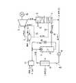
図1は本発明の冷熱利用発電システムの概略図であり、本システムは、燃焼器1と、ガスタービン2と、廃熱ボイラ3と、凝縮器4と、コンプレッサ5と、気化器6と、貯蔵タンク7と、ポンプ8により、閉ループサイクル9を形成している。そして、作業流体である二酸化炭素(CO2)が、上記閉ループサイクル9を循環するようになっている。
【0012】
上記燃焼器1は、液化天然ガス(LNG)を燃料cとしており、これに極力理論空気量に相当する量の純酸素(O2)bを供給して燃焼させている。燃焼器1で生じた高温高圧の燃焼ガスdは、ガスタービン2に導入され、発電機10を駆動する動力源になっている。
【0013】
上記ガスタービン2から排出された排ガスeは、廃熱回収する廃熱ボイラ3を経て凝縮器4に導入される。凝縮器4は、ポンプ8によって昇圧された0℃以下の二酸化炭素ハイドレート又はクラスレート(以下、包接化合物と称する)hを利用して排ガスe中の蒸気(H2O)を凝集し、除去するようになっている。
【0014】
蒸気(H2O)を分離したガス状の二酸化炭素(CO2)gは、作業流体として閉ループサイクル9に戻されるが、燃焼の際に生じた余分な二酸化炭素などは、排気fとして大気中に放出される。
【0015】
ガス状の二酸化炭素(CO2)gは、コンプレッサ5によって昇圧(2atm)されたのち、気化器6に導入される。そして、液化天然ガス(LNG)jと熱交換して液化天然ガス(LNG)jをガス化させる一方、自分自身も0℃以下、即ち、マイナス45℃に冷却される。
【0016】
LNGによってマイナス45℃に冷却されたガス状の二酸化炭素gは、純水(H2O)w、およびアルコールやアルコール類などの溶媒iと一緒に図示しないノズルから貯蔵タンク7内に噴出され、包接化合物hを選択的に生成する。貯蔵タンク7に貯蔵された包接化合物hは、ポンプ8によってガスタービン2の要求圧まで昇圧されたのち、凝縮器4に供給される。そして、ガスタービン2の排ガスeと熱交換して分解されたのち、高圧の作業流体ガス(二酸化炭素及び蒸気)aとして燃焼器1に供給される。
【0017】
溶媒iの一部は、比重差を利用して包接化合物hから分離され、ポンプ15を有する循環ライン16を経て図示しないノズルに戻される。水槽11には、純水w及び溶媒iが補給されるようになっている。
【0018】
一方、ガスタービン2の高温部分、例えば、タービン翼(図示せず)の部分は、燃焼器1の手前で配管12から分岐した分岐管13を経て供給される高圧の作業流体ガス(二酸化炭素及び蒸気)aによって冷却されるようになっている。また、廃熱ボイラ3は、起動用バーナー14を備えている。
【0019】
一般に、純酸素(O2)の製造に要する原単価は高いが、LNGが保有している冷熱を利用した深冷分離法を利用すると、比較的安価に純酸素(O2)を製造することができる。
【0020】
【実施例】
(実施例)
本発明の発電効率と、通常のガスタービン発電(以下、通常のGT発電と称する)の発電効率を「表1」に示す。この「表1」から本発明の方が通常のGT発電より発電効率が格段に高いことが分かる。
【0021】
なお、発電出力は、いずれも、24,000kWに設定した。また、「表1」中、※1は、残存酸素が3.6%有り、また、※2は、深冷分離法による酸素製造時の製造動力を差し引いた後の発電効率を示している。
【0022】
【表1】
【発明の効果】
上記のように、本発明は、作業流体である高圧の二酸化炭素、蒸気及び酸素の存在下で燃料を燃焼させる燃焼器と、該燃焼器で生じた高温高圧の燃焼ガスを動力源とするガスタービンと、該ガスタービンにより駆動される発電機と、前記ガスタービンの排ガスから廃熱を回収する廃熱ボイラと、該廃熱ボイラを経たガスタービン排ガス中から二酸化炭素を分離すると同時に低温高圧の包接化合物を分解させる凝縮器と、該凝縮器で分離された二酸化炭素を昇圧するコンプレッサと、該コンプレッサで昇圧された二酸化炭素と液化天然ガスとを熱交換させて液化天然ガスをガス化させると同時に昇圧された二酸化炭素を0℃以下に冷却する気化器と、該気化器で冷却された二酸化炭素と純水及び溶媒を混合反応させて生成した包接化合物を蓄える貯蔵タンクと、該貯蔵タンクに蓄えられている包接化合物をガスタービンの要求圧まで昇圧するポンプにより閉ループサイクルを形成させたので、次のような優れた効果を有する。
【0024】
すなわち、
▲1▼ LNGの冷熱を有効に利用することにより、従来、海に捨てられていたLNGの液化エネルギーの一部を電力として高効率で回収することが可能になった。
【0025】
▲2▼ 作業流体である二酸化炭素に付与する純水中にアルコールやアルコール類などの溶媒を混合させることにより、純水の製氷現象を抑制することが可能になり、安定した運転が可能になった。
【0026】
▲3▼ 燃焼に必要な酸素濃度を任意に制御できるため、燃焼排ガス中の酸素濃度を少なくでき、NOxなどの削減にも寄与することが可能である。
【0027】
▲4▼ 通常の空気圧縮機が不要であり、既存のガスタービンよりコスト的に安価である。
【0028】
▲5▼ 凝縮器の作業流体(非凝縮ガス)の分圧を増大することができ、凝縮器をコンパクト化することが可能になった。
【図面の簡単な説明】
【図1】本発明に係る冷熱利用発電システムの系統図である。
【符号の説明】
1 燃焼器
2 ガスタービン
3 廃熱ボイラ
4 凝縮器
5 コンプレッサ
6 気化器
7 貯蔵タンク
8 ポンプ
9 閉ループサイクル
10 発電機
b 酸素
c 燃料
d 燃焼ガス
e ガスタービン排ガス
g 二酸化炭素
h 包接化合物
i 溶媒
j 液化天然ガス
w 純水[0001]
BACKGROUND OF THE INVENTION
The present invention relates to a cold-use power generation system that generates power by effectively using cold heat held by liquefied natural gas (hereinafter referred to as LNG).
[0002]
[Prior art]
Despite the enormous amount of cold heat held by LNG, seawater is used for gasification of LNG, so that the majority of the liquefaction energy of LNG is discarded in the sea. LNG uses only about 25% of cold.
[0003]
[Problems to be solved by the invention]
As a method of utilizing the cold energy of LNG, there are a cryogenic separation of air, a cold power generation, a low-temperature crushing, etc. Among them, the cold power generation seems to be the most effective method.
[0004]
However, since the conventional cold power generation uses the conventional Rankine cycle method, it is inefficient and has a lower output than the LNG to be processed.
[0005]
An object of the present invention is to provide a cold power generation system that solves the conventional problems and that can efficiently use the cold energy of LNG to generate electric power with high efficiency.
[0006]
[Means for Solving the Problems]
In order to solve the above problems, a cold power generation system according to the present invention includes a combustor that burns fuel in the presence of high-pressure carbon dioxide, steam, and oxygen that are working fluids, and a high-temperature and high-pressure generated in the combustor. A gas turbine that uses the combustion gas as a power source, a generator driven by the gas turbine, a waste heat boiler that recovers waste heat from the exhaust gas of the gas turbine, and gas turbine exhaust gas that has passed through the waste heat boiler A condenser that separates carbon dioxide and simultaneously decomposes a low-temperature and high-pressure clathrate compound, a compressor that pressurizes the carbon dioxide separated by the condenser, and heat exchange between the carbon dioxide pressurized by the compressor and liquefied natural gas Gasifying the liquefied natural gas and simultaneously cooling the pressurized carbon dioxide to 0 ° C. or lower, and the carbon dioxide, pure water and solvent cooled by the vaporizer A storage tank for storing a mixed clathrate compound reacted generated, it is characterized by comprising forming a closed loop cycle by a pump for boosting the clathrate to demand pressure of a gas turbine, which is stored in said storage tank.
[0007]
According to the present invention, carbon dioxide boosted by a compressor and LNG are subjected to heat exchange in a vaporizer to gasify LNG, while carbon dioxide is cooled to 0 ° C. or lower using the cold heat of LNG. Then, carbon dioxide cooled to 0 ° C. or less, pure water, and a solvent are mixed to produce a hydrate or clathrate (hereinafter referred to as an inclusion compound). The clathrate compound stored in the storage tank is pressurized to the required pressure of the gas turbine by a pump and then exchanges heat with the exhaust gas of the gas turbine while passing through the condenser to separate carbon dioxide in the gas turbine exhaust gas. On the other hand, it decomposes itself and is supplied to the combustor as working fluid gas, that is, high-pressure carbon dioxide and steam.
[0008]
More specifically, the ice-making phenomenon of pure water is given priority when mixing carbon dioxide cooled to 0 ° C. or less with the cold heat of liquefied natural gas (LNG) and pure water, and it may be difficult to produce an inclusion compound. When a certain kind of solvent such as alcohol or alcohol is mixed in pure water, it is possible to selectively produce an clathrate compound without freezing of pure water. . The solvent is circulated and used because it can be separated from the inclusion compound by utilizing the specific gravity difference.
[0009]
On the other hand, the hot part of the gas turbine can be cooled by introducing a part of the working fluid (carbon dioxide and steam) supplied to the combustor into the hot part of the gas turbine, for example, the turbine cascade.
[0010]
DETAILED DESCRIPTION OF THE INVENTION
Hereinafter, embodiments of the present invention will be described with reference to the drawings.
[0011]
FIG. 1 is a schematic diagram of a cold power generation system of the present invention, which includes a combustor 1, a gas turbine 2, a
[0012]
The combustor 1 uses liquefied natural gas (LNG) as a fuel c, and supplies pure oxygen (O2 ) b corresponding to the theoretical air amount as much as possible to burn it. The high-temperature and high-pressure combustion gas d generated in the combustor 1 is introduced into the gas turbine 2 and serves as a power source for driving the
[0013]
The exhaust gas e discharged from the gas turbine 2 is introduced into the
[0014]
Gaseous carbon dioxide (CO2 ) g from which the vapor (H2 O) has been separated is returned to the closed-
[0015]
Gaseous carbon dioxide (CO2 ) g is pressurized (2 atm) by the compressor 5 and then introduced into the
[0016]
Gaseous carbon dioxide g cooled to minus 45 ° C. by LNG is jetted into the storage tank 7 from a nozzle (not shown) together with pure water (H2 O) w and a solvent i such as alcohol or alcohols, The inclusion compound h is selectively produced. The clathrate compound h stored in the storage tank 7 is pressurized to the required pressure of the gas turbine 2 by the pump 8 and then supplied to the
[0017]
A part of the solvent i is separated from the inclusion compound h by utilizing the specific gravity difference, and returned to a nozzle (not shown) through a circulation line 16 having a pump 15. The
[0018]
On the other hand, a high-temperature portion of the gas turbine 2, for example, a portion of a turbine blade (not shown), is supplied with a high-pressure working fluid gas (carbon dioxide and carbon dioxide) supplied via a
[0019]
In general, the unit cost required for the production of pure oxygen (O2 ) is high. However, when the cryogenic separation method using the cold energy of LNG is used, pure oxygen (O2 ) is produced at a relatively low cost. Can do.
[0020]
【Example】
(Example)
Table 1 shows the power generation efficiency of the present invention and the power generation efficiency of normal gas turbine power generation (hereinafter referred to as normal GT power generation). From this “Table 1”, it can be seen that the power generation efficiency of the present invention is much higher than that of normal GT power generation.
[0021]
In addition, all the power generation outputs were set to 24,000 kW. In Table 1, * 1 indicates 3.6% residual oxygen, and * 2 indicates power generation efficiency after subtracting the production power during oxygen production by the cryogenic separation method.
[0022]
[Table 1]
【The invention's effect】
As described above, the present invention provides a combustor that burns fuel in the presence of high-pressure carbon dioxide, steam, and oxygen that are working fluids, and a gas that uses a high-temperature and high-pressure combustion gas generated in the combustor as a power source. A turbine, a generator driven by the gas turbine, a waste heat boiler that recovers waste heat from the exhaust gas of the gas turbine, and at the same time separating carbon dioxide from the gas turbine exhaust gas that has passed through the waste heat boiler. A condenser that decomposes the clathrate compound, a compressor that pressurizes the carbon dioxide separated by the condenser, and carbon dioxide that has been pressurized by the compressor and liquefied natural gas are heat-exchanged to gasify the liquefied natural gas. At the same time, a vaporizer that cools the pressurized carbon dioxide to 0 ° C. or lower, and a clathrate compound produced by mixing and reacting the carbon dioxide cooled with the vaporizer with pure water and a solvent are stored. And storage tanks, because the inclusion compounds are accumulated in the reservoir tank to form a closed loop cycle by a pump to boost to the required pressure of a gas turbine, has excellent effects as follows.
[0024]
That is,
(1) By effectively utilizing the cold energy of LNG, it has become possible to efficiently recover a part of the liquefaction energy of LNG that has been discarded in the sea as electric power.
[0025]
(2) By mixing a solvent such as alcohol or alcohol into pure water given to carbon dioxide, which is the working fluid, it becomes possible to suppress the ice-making phenomenon of pure water and to enable stable operation. It was.
[0026]
{Circle around (3)} Since the oxygen concentration necessary for combustion can be controlled arbitrarily, the oxygen concentration in the combustion exhaust gas can be reduced, and it is possible to contribute to the reduction of NOx and the like.
[0027]
(4) A normal air compressor is unnecessary, and it is cheaper than existing gas turbines.
[0028]
(5) The partial pressure of the working fluid (non-condensable gas) of the condenser can be increased, and the condenser can be made compact.
[Brief description of the drawings]
FIG. 1 is a system diagram of a cold power generation system according to the present invention.
[Explanation of symbols]
DESCRIPTION OF SYMBOLS 1 Combustor 2
Claims (2)
Translated fromJapanesePriority Applications (1)
| Application Number | Priority Date | Filing Date | Title |
|---|---|---|---|
| JP26526499AJP4094185B2 (en) | 1999-08-24 | 1999-09-20 | Cold power generation system |
Applications Claiming Priority (3)
| Application Number | Priority Date | Filing Date | Title |
|---|---|---|---|
| JP11-237160 | 1999-08-24 | ||
| JP23716099 | 1999-08-24 | ||
| JP26526499AJP4094185B2 (en) | 1999-08-24 | 1999-09-20 | Cold power generation system |
Publications (2)
| Publication Number | Publication Date |
|---|---|
| JP2001132472A JP2001132472A (en) | 2001-05-15 |
| JP4094185B2true JP4094185B2 (en) | 2008-06-04 |
Family
ID=26533079
Family Applications (1)
| Application Number | Title | Priority Date | Filing Date |
|---|---|---|---|
| JP26526499AExpired - Fee RelatedJP4094185B2 (en) | 1999-08-24 | 1999-09-20 | Cold power generation system |
Country Status (1)
| Country | Link |
|---|---|
| JP (1) | JP4094185B2 (en) |
Families Citing this family (21)
| Publication number | Priority date | Publication date | Assignee | Title |
|---|---|---|---|---|
| CA2519145C (en)* | 2003-03-18 | 2009-11-03 | Fluor Corporation | Humid air turbine cycle with carbon dioxide recovery |
| JP4644804B2 (en)* | 2005-03-31 | 2011-03-09 | 独立行政法人産業技術総合研究所 | Carbon dioxide recovery method and apparatus for recovering carbon dioxide in exhaust gas |
| US8596075B2 (en) | 2009-02-26 | 2013-12-03 | Palmer Labs, Llc | System and method for high efficiency power generation using a carbon dioxide circulating working fluid |
| US10018115B2 (en) | 2009-02-26 | 2018-07-10 | 8 Rivers Capital, Llc | System and method for high efficiency power generation using a carbon dioxide circulating working fluid |
| ES2733083T3 (en) | 2009-02-26 | 2019-11-27 | 8 Rivers Capital Llc | Apparatus and method for burning a fuel at high pressure and high temperature, and associated system and device |
| CA2854402C (en) | 2011-11-02 | 2020-03-24 | 8 Rivers Capital, Llc | Power generating system and corresponding method |
| CN104302743B (en) | 2012-02-11 | 2016-11-09 | 帕尔默实验室有限责任公司 | Partial Oxidation Reactions with Closed Cycle Quenching |
| JP6250332B2 (en) | 2013-08-27 | 2017-12-20 | 8 リバーズ キャピタル,エルエルシー | Gas turbine equipment |
| TWI691644B (en) | 2014-07-08 | 2020-04-21 | 美商八河資本有限公司 | Method and system for power production with improved efficiency |
| US11231224B2 (en) | 2014-09-09 | 2022-01-25 | 8 Rivers Capital, Llc | Production of low pressure liquid carbon dioxide from a power production system and method |
| MY176626A (en) | 2014-09-09 | 2020-08-19 | 8 Rivers Capital Llc | Production of low pressure liquid carbon dioxide from a power production system and method |
| MA40950A (en) | 2014-11-12 | 2017-09-19 | 8 Rivers Capital Llc | SUITABLE CONTROL SYSTEMS AND PROCEDURES FOR USE WITH POWER GENERATION SYSTEMS AND PROCESSES |
| US11686258B2 (en) | 2014-11-12 | 2023-06-27 | 8 Rivers Capital, Llc | Control systems and methods suitable for use with power production systems and methods |
| US10961920B2 (en) | 2018-10-02 | 2021-03-30 | 8 Rivers Capital, Llc | Control systems and methods suitable for use with power production systems and methods |
| KR102602774B1 (en) | 2015-06-15 | 2023-11-15 | 8 리버스 캐피탈, 엘엘씨 | System and method for starting up a power production plant |
| CA3015050C (en) | 2016-02-18 | 2024-01-02 | 8 Rivers Capital, Llc | System and method for power production including methanation |
| MY190077A (en) | 2016-02-26 | 2022-03-24 | 8 Rivers Capital Llc | Systems and methods for controlling a power plant |
| EA039851B1 (en) | 2016-09-13 | 2022-03-21 | 8 Риверз Кэпитл, Ллк | System and method for power production using partial oxidation |
| BR112020003886A2 (en) | 2017-08-28 | 2020-09-01 | 8 Rivers Capital, Llc | low-grade heat optimization of recoverable supercritical co2 energy cycles |
| EP3759322B9 (en) | 2018-03-02 | 2024-02-14 | 8 Rivers Capital, LLC | Systems and methods for power production using a carbon dioxide working fluid |
| EP4520935A3 (en) | 2019-10-22 | 2025-05-21 | 8 Rivers Capital, LLC | Control schemes for thermal management of power production systems and methods |
- 1999
- 1999-09-20JPJP26526499Apatent/JP4094185B2/ennot_activeExpired - Fee Related
Also Published As
| Publication number | Publication date |
|---|---|
| JP2001132472A (en) | 2001-05-15 |
Similar Documents
| Publication | Publication Date | Title |
|---|---|---|
| JP4094185B2 (en) | Cold power generation system | |
| US7827794B1 (en) | Ultra low emissions fast starting power plant | |
| KR102004700B1 (en) | Supercritical carbon dioxide power generation system of oxy fuel combustion | |
| RU2009106714A (en) | METHOD AND DEVICE FOR EFFICIENT AND LOW-TOXIC OPERATION OF POWER PLANTS, AND ALSO FOR ACCUMULATION AND ENERGY CONVERSION | |
| CN110685757A (en) | LNG-based gas turbine-supercritical CO2ORC cycle parallel power generation system | |
| JP2002097965A (en) | Power generation system using cold heat | |
| CN101720381A (en) | Arrangement with a steam turbine and a condenser | |
| CN101566104B (en) | Method and device for zero emission of carbon dioxide by utilizing liquid hydrogen condensation | |
| US20240401520A1 (en) | Gas turbine plant with ammonia decomposition system | |
| US11988114B2 (en) | H2 boiler for steam system | |
| JP6764798B2 (en) | Plant and plant operation method | |
| JP7351648B2 (en) | complex plant | |
| JP2971378B2 (en) | Hydrogen combustion gas turbine plant and operation method thereof | |
| CN113982711B (en) | An integrated power generation system based on LNG-PEMFC-compressed air energy storage-low temperature power cycle | |
| US20240401519A1 (en) | Gas turbine plant with ammonia decomposition system | |
| JP6946012B2 (en) | CO2 liquefaction system and CO2 liquefaction method | |
| JP2662298B2 (en) | Power plant with carbon dioxide separator | |
| CN109630269B (en) | Natural gas-steam combined cycle clean power generation process | |
| JP2001159318A (en) | Cold power generator | |
| JPH11270347A (en) | Gas turbine combined power generation device using LNG | |
| JP2004224661A (en) | Combined power generation and hydrogen generation plant | |
| CN114718730A (en) | A hydrogen-fired gas turbine system and control method for converting ammonia into hydrogen | |
| JPH04191418A (en) | Carbon dioxide (co2) recovering power generation plant | |
| KR101371253B1 (en) | A combined system of lng regasification and power generation | |
| CN110735678B (en) | Power circulation system independent of air propulsion device |
Legal Events
| Date | Code | Title | Description |
|---|---|---|---|
| A621 | Written request for application examination | Free format text:JAPANESE INTERMEDIATE CODE: A621 Effective date:20060317 | |
| A977 | Report on retrieval | Free format text:JAPANESE INTERMEDIATE CODE: A971007 Effective date:20080218 | |
| TRDD | Decision of grant or rejection written | ||
| A01 | Written decision to grant a patent or to grant a registration (utility model) | Free format text:JAPANESE INTERMEDIATE CODE: A01 Effective date:20080226 | |
| A61 | First payment of annual fees (during grant procedure) | Free format text:JAPANESE INTERMEDIATE CODE: A61 Effective date:20080305 | |
| FPAY | Renewal fee payment (event date is renewal date of database) | Free format text:PAYMENT UNTIL: 20110314 Year of fee payment:3 | |
| R150 | Certificate of patent or registration of utility model | Free format text:JAPANESE INTERMEDIATE CODE: R150 | |
| FPAY | Renewal fee payment (event date is renewal date of database) | Free format text:PAYMENT UNTIL: 20110314 Year of fee payment:3 | |
| FPAY | Renewal fee payment (event date is renewal date of database) | Free format text:PAYMENT UNTIL: 20120314 Year of fee payment:4 | |
| FPAY | Renewal fee payment (event date is renewal date of database) | Free format text:PAYMENT UNTIL: 20140314 Year of fee payment:6 | |
| LAPS | Cancellation because of no payment of annual fees |